Firetide 8020-1 Firetide Wireless Mesh Node User Manual rev
Firetide Inc. Firetide Wireless Mesh Node Users Manual rev
Firetide >
Users Manual_rev.pdf
Firetide
Installation Guide
HotPort 8020Mesh Node
Published Dec 2017
Revised Feb 2018

HotPort 8020 Mesh Node Installation Guide
1
© 2017 Firetide, Inc
.
All rights reserved
.
F
i
ret
i
de
,
the F
i
ret
i
de
l
ogo
,
HotPort are a
ll
trademarks of Firetide Inc. A
ll
other trademarks are
the property of the
i
r
respective
owners.
Informat
i
on
i
n th
i
s document
i
s subject to
change w
i
thout not
i
ce.
F
i
re
tid
e
, Inc
.
2105S. Bascom Avenue
,
Su
i
te 220
Campbell,
CA
95008
USA
www.firetide.com
HotPort 8020 Mesh Node Installation Guide
2
Contents
1 About this document............................................................................................................................ 4
1.1
Audience
............................................................................................................................................. 4
1.2
Instructions to purchaser and installer
...................................................................................................... 4
1.3
Purpose
............................................................................................................................................... 4
1.4
Conventions
......................................................................................................................................... 4
1.5
Document feedback
............................................................................................................................... 4
1.6
Contacting customer support
.................................................................................................................. 4
2 HotPort 8020 mesh node ..................................................................................................................... 5
3 Installation ............................................................................................................................................ 5
Preparing what you need to install ........................................................................................................... 5
3.1
HotPort mesh node in an IP67 enclosure
.................................................................................................. 6
3.1.1
Package contents of 8020 mesh node
............................................................................................... 6
The following accessories can be purchased separately from Firetide
................................................................. 6
3.2
Interface of an outdoor mesh
.................................................................................................................. 7
3.2.1
Node LEDs
.................................................................................................................................... 8
3.2.2
Console Port/Reset
........................................................................................................................ 9
3.2.3
Ethernet ports
............................................................................................................................... 9
3.2.4
Antenna Connectors
.................................................................................................................... 10
3.2.5
Pressure relief valve
..................................................................................................................... 10
3.2.6
Ground screw point
..................................................................................................................... 10
4 Test before you install ........................................................................................................................ 10
4.1
Before you install:
............................................................................................................................... 10
4.2
Tests to do
......................................................................................................................................... 10
4.3
Licenses which are not included
............................................................................................................ 10
4.4
Certification requirement
..................................................................................................................... 10
5
Doing the tests
....................................................................................................................................... 10
6
Power Specifications
............................................................................................................................... 12
6.1
Power input and Power out
.................................................................................................................. 12
6.2
Operating TX Power limit of radio
.......................................................................................................... 12
7
Environmental
Specifications
............................................................................................................... 12
8
HotPort8020 mesh node installation
.................................................................................................... 12
HotPort 8020 Mesh Node Installation Guide
3
8.1
Installation Steps:
................................................................................................................................ 12
8.2
Tools required
.................................................................................................................................... 12
8.3
Doing the site survey
........................................................................................................................... 13
8.4
Safe installation practices
..................................................................................................................... 13
8.5
Preparing a mesh node for installation
................................................................................................... 14
8.6
Preparing earth ground
........................................................................................................................ 15
8.7
Installing a mesh node and antenna assembly
......................................................................................... 16
8.8
Attaching the mesh node to a wall
......................................................................................................... 17
8.9
Attaching a mesh node to a vertical pole
................................................................................................ 18
8.10
Attaching a mesh node to a horizontal pole
............................................................................................. 19
8.11
Panel antenna Assembly
...................................................................................................................... 21
8.12
Mesh node installation with RF cable assembly on a vertical pole.
.............................................................. 22
9 Trouble shooting ................................................................................................................................ 24
Cannot see a mesh node in Web NMS.................................................................................................... 24
After multiple reboots a mesh node is missing ........................................................................................ 24
Performance not as expected ................................................................................................................. 24
Resetting an outdoor mesh node to factory default settings ................................................................. 25
10 Weather proof procedures ............................................................................................................ 26
10.1
Tools and materials ........................................................................................................................ 26
To make a weatherproof connection you need the following tools and materials: .............................. 26
Making weatherproof cable to node connections.................................................................................. 26
Y
ou need to make weather proof two connections:
.................................................................................... 26
To make a weather proof cable to node connection: ............................................................................ 26
11 Information to User, Purchaser & Installer ................................................................................... 28
11.1
Federal Communication Commission Interference Statement .................................................... 28

HotPort 8020 Mesh Node Installation Guide
4
1 About this document
This section lists the audience, purpose, summary of information, and conventions used in this document.
1.1
Audience
This documents intended for certified professionals who install Firetide wireless solutions.
1.2
Instructions to purchaser and installer
This equipment must be professionally installed. The installer is responsible for adjusting the transmit power output of the
system to assure compliance with FCC Part15 EIRP limits and human radiation safety regulations.
1.3
Purpose
This document has the information and procedures necessary to install and do basic tests with Firetide HotPort 8020 mesh
node.
1.4
Conventions
Certaininformationhasspecialmeaningforthereader.Thisinformationappearswith an icon that indicates a particular condition,
such as a warning or caution, or a label, such as “Note” or “Best Practice”.
Electrical hazards are those environments where the danger of electrocution is probable. This image appears
before each electrical hazard statement.
Warnings contain safety information that you must obey. If you do not obey the instruction in warning, the result
might include serious injury or death. This image appears before each warning statement.
Cautions contain information that you should obey to avoid minor injury, inconvenience, and damage to equipment.
This image appears before each caution statement.
Notes contain optional advice and information particular to a special case or application.
Best practices contain specific recommendations based on industry-standard expectations.
1.5
Document feedback
If you find an error or content missing from this document, we want to hear about it. You can send you feedback about any
of our documents to FT-Techpubs@firetide.com.
1.6
Contacting customer support
If you need support, depending on the problem, you might be asked for this information:
Description of the problem
FMA and an installed management license
Channel and frequency plan
Recent spectrum analysis
Device topology in Google Earth (KMZ file)
Network map or topology plan with device information
You must also have administrator access to the mesh to be able to receive technical support.
The next table lists the contact information for customer support.
Worldwide
customer
support
Days/Hours Contact
Americas
Monday to Friday
7:00 am
to
5:30
pm
PST
(Pacific Standard
T ime)
http://www.firetide.com/support
+1
(877)
FIRETIDE,
extension 2
+1
(408) 399-7771, extension 2
+1
(408) 355-7271
HotPort 8020 Mesh Node Installation Guide
5
Africa
Asia
Australia
Europe
Monday to Friday
8:00
am to 5:30 pm
IST
(India
Standard Time)
http://www.firetide.com/support
+91-8040215111
Fax
+1(408)
317-2257
2 HotPort 8020 mesh node
Firetide
HotPort
TM
mesh
node
has
two
radios
which
operate in 802.11a, n
and
ac
4x4
MIMO
mode.
The default configuration is 2x2 MIMO. With Software license 4x4
MIMO can be enabled.
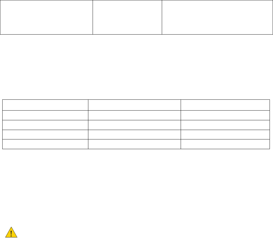
The following
software
licenses
are
available. **
License
Descriptions
Remarks
SW-8020-2x2MIMO
802.11n/ac 2x2MIMO
Default
SW-8020-4x4MIMO
802
.11
n
/
ac
4x4
MIMO
Add
on
license
SW-FMA-Mgmt.
Management
License
Add
on
license
SW-Mobility
Mobility
License
Add
on
license
If you plan on using DFS, it is mandatory to take training class from Firetide. On successful completion of the class Firetide
will provide login credentials for DFS configuration using Firetide Management Appliance.
**Subject to software implementation.
3 Installation
Please read before Installation
You
must
complete the training program and
be
certified by Firetide to be
able
to
install
Firetide
products.
Before you
install
an
outdoor
mesh node
in
a
permanent
location,
you
need
to
make
sure
you
have
all
of
the
correct
components
and
make
sure
the
components
are
operational.
Preparing what you need to install
To
get
what
you
need
to
set
up
a
mesh node:
Open the box.
Remove the contents.
Check the contents for damage. If a part is missing or damaged, call your Firetide reseller.
If the contents are good and correct, keep the box for future use.

HotPort 8020 Mesh Node Installation Guide
6
3.1
HotPort mesh node in an IP67 enclosure
3.1.1
Package contents of 8020 mesh node
Eight detachable 5GHz Omni- directional antennas for staging
Pole and wall mounting kit
Mounting screws and bolts
Ground cable
Cat6 Ethernet cable
The following accessories can be purchased separately from Firetide
4x4 MIMO 18.5 dBi gain 5G panel outdoor rated antenna
7 dBi gain 5G dipole antenna
RF cable assembly with lightning arrester
802.3 AT+ PoE injector
HotPort 8020 Mesh Node Installation Guide
7
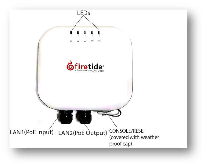
3.2
Interface of an outdoor mesh
The following picture of 8020 mesh node shows the
front view and the rear view
describing
node LEDs, antenna port connectors of the radio, Ethernet ports(PoE input and PSE output port),
debug console/reset and the pressure valve with weatherproof cap protection and node ground
point.
For information about cables and accessories approved for use with Firetide devices,
refer to the Accessories Guide.
Front View
HotPort 8020 Mesh Node Installation Guide
8
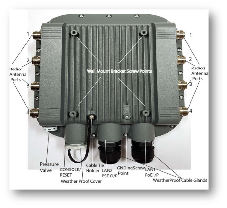
Rear View
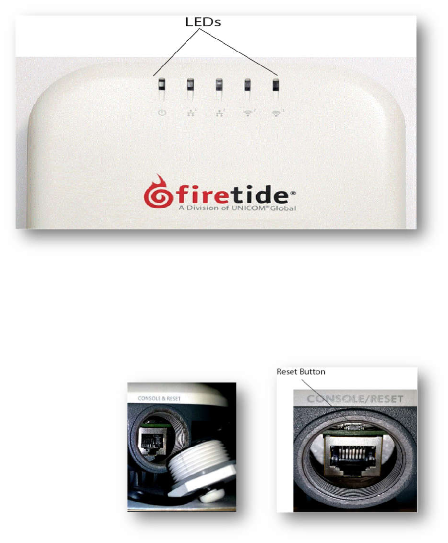
3.2.1
Node LEDs
Hotport8020 mesh node has 5 LEDs as shown in the following picture.
o
Power LED
OFF: Mesh node does not receive power.
Amber: Device is powering up
Green: Device is powered up and ready to use
o
Ethernet LEDs of LAN1 and LAN2 port
OFF: No Ethernet link detected
Amber: Link speed (10/100 Mbps),Blinking - Activity
Green-Link speed (1000Mbps), Blinking- Activity
o
Radio1 and Radio2 LEDs
OFF: No Radio neighbor detected
Green: Radio Neighbor connected, Blinking-Activity
HotPort 8020 Mesh Node Installation Guide
9
3.2.2
Console Port/Reset
Console port and reset button are co-located as shown in the picture below, which is covered by a weatherproof
cap, held with a cable tie.
Note: Console port is meant to be used only for debugging purpose by Firetide support.
Reset button is above the console port RJ45 connector.
Refer the “procedure for reset” on page 24 to do a factory reset of the mesh node.
3.2.3
Ethernet ports
o
Ports 1 & 2 of HotPort 8020 mesh node are Gigabit Ethernet LAN ports.
o
LAN1 Port can receive power from an 802.3at+ compliant PoE source.
o
LAN2 Port can source power to an 802.3af compliant device.
HotPort 8020 Mesh Node Installation Guide
10
3.2.4
Antenna Connectors
o
HotPort
8020
mesh
node
has
eight
N
type
female
antenna
connectors,
four connectors
per
radio
.
3.2.5
Pressure relief valve
o
The pressure relief valve
shown
on
the
rear
cover
is
protected
by a
weatherproof cap
.
3.2.6
Ground screw point
o
The ground screw is on the lower left
side
of the bottom cover.
Adequate
grounding
of
the mesh
node
must
be
ensured.
4 Test before you install
You should set
up
and
test the
mesh nod in door
on
a
table before you install
them
in
permanent
locations.
4.1
Before you install:
o
Make sure all of the equipment are in working condition
o
Configure mesh nodes to reduce configuration effort in the field
o
Test the stability and performance of the nodes.
4.2
Tests to do
o
Power on each device
o
Attach all antennas and make sure you can see all devices in Web NMS
o
Perform throughput test
4.3
Licenses which are not included
FMA
network
management
software
and
appropriate
licenses
are
required.
Before
you set
up the
network,
you
must
purchase
all
licenses
from
your
Firetide
distributor.
For
the
procedures
related
to
license
installation, refer
to
the
FMA
Reference Manual.
4.4
Certification requirement
Professionals who install and manage networks that contain Firetide products
must comply
with
the
training and certification
requirements
of
the
installation.
5
Doing the tests
For efficiency, you can configure six to eight mesh nodes at one time. To do tests and capture data with
FMA software:
1.
Refer
to
the
FMA
product
guide
for
the
prerequisites
of
HW
requirement.
2.
Connect the power cable to the PoE adaptor, connect through CAT5e / CAT6 Ethernet cable
from the PoE output of PoE Adaptor to LAN1 PoE input port of the mesh node.
3.
Attach the staging antennas to each mesh node
4.
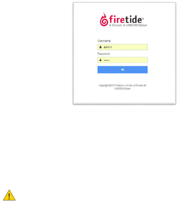
FMA can be accessed through it’s URL using an internet browser. It will launch the login page.
HotPort 8020 Mesh Node Installation Guide
11
5.
Enter user name and password to login. The default username and password is: admin / admin.
The picture
below shows the
Login
screen.
6.
Make
sure
that
all
mesh
nodes
are
loaded
in
FMA. i
f
you
can not
see
any
or all
o
f
the
mesh
nodes,
see
the
troubleshooting
information
in
the
FMA
Product
Guide
7.
S
et
the country
code on
the
nodes
.
All
nodes
intended
f
or
use
in
the
United
S
tates
will
be set to
U
S
Country
code.
Once
the
U
S
Country
code
is
set,
changing
to
a
di
ff
erent
Country
code later
will
not
be
possible.
Caution: Make sure you configure the device for the correct country. If you do not
configure the country correctly, the device might operate in a manner that is not legal
in that country and/or create problems with other wireless devices
a)
Go
to
Mesh
configurations,
Select
the
country
of
operation
from
the
drop-down
list.
b)
Save
Mesh
configurations.
When you set the country code the system refreshes the
mesh configuration
and
gives
all
visible
nodes
in
the
same
country
code.
For
a
few
minutes
the mesh
nodes
might
disappear
from
the
topology
view
in
WebNMS
.
8.
To
configure
mesh-wide
settings,
go
to
Mesh
>
Configure
Mesh...
Set
the
radio
operational
mode
as
needed.
Not
e
:
For information
about
specific
features
and
the configuration
process,
see
the FMA
Reference Manual.
9.
Check
network
throughput
on
each
link
between
mesh
nodes.
For
procedures,
see
the
FMA
Product
Configuration
Guide
.
Note: If you are not able to send and/or receive data, see “Troubleshooting” on
page 23.
10.
After
you
finish
the
tests,
remove the
staging
antennas.
HotPort 8020 Mesh Node Installation Guide
12
6
Power Specifications
6.1
Power input and Power out
Power input: LAN1 port: IEEE 802.3at+ compliant, PoE-PD
Power output: LAN2 port: IEEE 802.3af compliant, PoE-PSE
6.2
Operating TX Power limit of radio
Allowed Radio Power limits, supported frequencies and channel bandwidth shall vary based on country/region
of operation and
Operating TX Power is compliant to FCC 15.407(a) power limit.
7
Environmental
Specifications
Operating
temperature:
-30
o
C
to
+
60
o
C
Storage
temperature:
-40
o
C
to
+70
o
C
Humidity
(non-condensing):
10
%
to
90
%
Storage
humidity
(non-condensing):
5
%
to
95
%
Max
altitude:
15,000
ft.
(4,600
meters)
8
HotPort8020 mesh node installation
The
configured mesh nodes are ready for installation
in
the
permanent
outdoor location.
8.1
Installation Steps:
1.
Do a site survey to make sure that no safety hazards are present.
2.
Gather all required tools.
3.
Prepare safety equipment
and
confirm
earth
ground
procedures.
4.
Attach the mesh nodes and antennas to poles that are attached to a mast, tower, or roof.
5.
Install the mesh node and
antennas assembly and other devices, such
as cameras.
8.2
Tools required
To
install
HotPort
8020 mesh
nodes,
you
need
to use:
Screwdriver
s
et
Small
adjustable
wrench
Wire cutters to cut tie wraps around cables
Electrical tape
and butyl masti c tape to weatherproof the connectors
Spray to prevent corrosion
Other equipment you might need includes:
Ladder
Lift truck
Safety
equipment
HotPort 8020 Mesh Node Installation Guide
13
8.3
Doing the site survey
Before you
install
any
equipment
outside,
check
the
entire site:
To
identify
possible
hazards
that
might
be
new
since
the
site
survey
To
identify the presence of objects that might
cause interference for
the radios
Warning!
Certified professionals must
install Firetide products. Failure
to
install
this
equipment correctly
can
result
in
equipment
damage,
personal
injury,
or
death.
Electrical shock hazard warning!
Make a plan to keep the installation
personnel safe.
Warning!
Do not
install Firetide products where possible contact with
power
lines
can
be
made.
Antennas,
poles,
towers,
guy
wires,
or
cables can touch power lines.
People can be injured or killed if they
touch
or hold any part of the
equipment when it contacts electric
lines.
Make sure
that
equipment
and
personnel
do not
directly
or
indirectly contact
power lines.
Warning!
Do
not
open
the
cover:
Dangerous voltages
inside.
No
serviceable
parts
inside.
8.4
Safe installation practices
Best
practice:
Install
HotPort
8020 mesh
nodes
on poles
that
are
at
sufficient
d
istance
from
power
lines.
The horizontal distance from a tower, pole or antenna to the nearest power line
should be at least twice the total length of the pole/antenna combination. This
distance ensures that the pole will not contact a power line if it falls during or after
installation.
Select equipment locations that allow safe and simple installation.
Do not work alone.
Use approved non-conducting ladders, shoes, and other safety equipment.
Make sure all equipment is in good condition.
If a tower or pole begins falling, do not catch it.
If a wire or pole touches a power line, do not touch it.
Do not install antennas or towers on windy days.
Make sure all towers and poles are correctly grounded.
Make sure all electrical cables connected to antennas have lightning arrestors.
A connection to earth ground and a lightning arrestor can prevent fire damage or
personal injury in case of lightning, static build-up, or short circuit within the
equipment connected to the antenna.
HotPort 8020 Mesh Node Installation Guide
14
Use 10AWG ground wire and corrosion-resistant connectors to connect the base of
the antenna pole or tower directly to the building protective ground or to one or
more approved grounding rods.
Refer to the National Electrical Code for grounding information.
8.5
Preparing a mesh node for installation
It is easier to install all devices to one object, such
as pole, and
then attach the
pole
assembly
to the roof. If you attach the devices to a pole attached to the roof
top, factors, such
as
weather, can make the installation
more difficult and
dangerous.
Warning!
Only use antennas that are rated for outdoor applications.
Warning!
Failure to comply with these installation instructions might result in severe personal injury
including electrical shock or permanent damage to equipment.
Warning!
Make sure that all safety equipment is in good condition. Do not use broken or damaged tools
or equipment. Always use safe work practices and obey all local and national guidance for earth ground
requirements and electricity.
Note:
Collect
all
tools
before
you
install
the
mesh
nodes.
Make sure that you have antennas rated for outdoor use. For information about antennas and how
to select them, see the Firetide Antenna and Accessory Guide.
Warning!
Max Operating TX Power allowed Power limits is as per FCC 15.407(a).
Note:
Install the antenna and
any other wireless devices higher than the HotPort
mesh node.
1.
To
a
pole
that
you
can
install
at a
permanent
outdoor
site,
attach
these
items:
a)
Brackets for
the
mesh
node
b)
Antenna
bracket
2.
Attach
the
antenna to the
antenna
bracket.
Refer
to the antenna
installation procedures.

HotPort 8020 Mesh Node Installation Guide
15
8.6
Preparing earth ground
Warning.
A Hot Port mesh node must be correcty connected to earth
ground.
Failure to
do
so
can result
in
equipment
damage,
injury,
or
death.
The
product warranty
does
not
include
damage
from
incorrect
grounding.
Obey
all
local
building
and
electrical
codes
regarding
antennas.
If not
available,
refer
to
the
National
Electric
Code
(NEC).
Earth
grounding
guidelines
include:
If you attach a mesh node and antenna to a tower or pole, attach the base of
the tower
pole to the building’s
ground
or
to
one
or
more
approved grounding
rods
with
10 AWG ground wire and
corrosion-resistant
connectors.
Connect the grounding cable to rain gutters only if the rain gutter is
connected
to
earth
ground.
Ground rods
are copper-plated and 1.8 to
2.4 meters
(6
to
8
feet)
long.
Install all ground components in straight lines. If you must make a bend, do not make a
sharp bend.
Earth-to-ground
should be
less
than
5
ohms.
Some salt compounds are corrosive and can cause copper ground rods
to
corrode.
To prepare the
soil
for
ground rods:
1
If
the
soil contains
rocks
or sand,
insert
the
ground rods
into
the
ground
Pull
out
the
ground rods.
2
Put in
an
approved
ground
enhancement
material
into the
holes
where
the
g
rounding
rods go.
Put in the ground rods.

HotPort 8020 Mesh Node Installation Guide
16
8.7
Installing a mesh node and antenna assembly
The
process to install antenna
to
a
mesh node for a
mast or
tower
or
to
a
roof
installation
are
same
.
Note:
Gather and take all tool s and
materials with you to the installation site.
Warning!
Do
not
install
this
pr
o
duct
on
a
win
dy
or
rain
y
d
a
y.
To
install a
mesh
node and antenna assembly
in a permanent outdoor
location:
1)
Safely
lift
and
carefully
put
the
assembly
on the
roof.
2)
Connecting to a MIMO antenna:
Terminate
the
unused
port
of
radio
antenna
ports
and
MIMO
antenna
ports
with
a
50
ohm
terminator.
If
your
MIMO
antenna
has
four
RF
Co nnectors
(two 45 degree connectors
and
two
90
degree
vertical
connector),
then
only
use
the two
45
degree
connectors.
DO
NOT
use
the
vertical
connector,
and place
a
50
ohm
terminator
on
the
vertical connector.
The
neighbor
antenna should
also
use
two
45
degree
connectors.
If
your
MIMO
antenna
has
four
connectors
(two
45
degree
connectors
and
two
90
degree
connector),
but
your
neighbor
MIMO
antennas
has
only
two
connectors
(two
90
degree
connectors),
then
mount
your
MIMO
antenna
with
the
two
90
degree
connectors
in
a
diamond
pattern.
The
MIMO
antenna
with
the
four
connectors
should
maintain
its
mount
in
a
square
pattern.
3)
Attach the pole to which the mesh node and antenna are attached to a mast, tower or
roof.
Attach the cables that have integrated lightning arrestors, or attach the cables and
install lightning arrestors.
Make drip loops with cables.
Connect earth ground. See “Preparing earth ground” on page 15.
4)
Make all connectors weatherproof. See “Weather proof procedures” on page 25.
5)
Connect the CAT5E/CAT6 Ethernet cable from PoE adaptor power port to LAN1 port of
the Mesh node.
6)
Cover all unused connectors, if any.
7)
Verify that the mesh node
works:
Ping the IP address
Use one or more mesh nodes
Do throughput tests with FMA and record the results as a benchmark test
HotPort 8020 Mesh Node Installation Guide
17
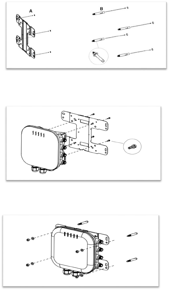
8.8
Attaching the mesh node to a wall
The below procedures shows how to install the Mesh node into a wall.
1)
Mark
the
four
locations
of
the
mounting
holes
on
the
flat
mounting
surface.
2)
Drill
37mm
deep
8mm
holes
on
the
markings
and
hammer
the
bolts
into
the
openings.
3)
Place the lock and flat washer on the four hex cap screws and drive the screws to attach
the bracket to the back of the Mesh node.
4)
Attach the device on to the wall by tightening the bolt’s flat washer and nuts to secure
the mounting base to the mounting surface.
HotPort 8020 Mesh Node Installation Guide
18
Note:
The
installation
is
correct
if
the
node
does
not
easily
move
from
side
to
side.
Best
practice:
Use
a
spray
to
prevent
corrosion
on
the
bracket
and
mount
hardware.
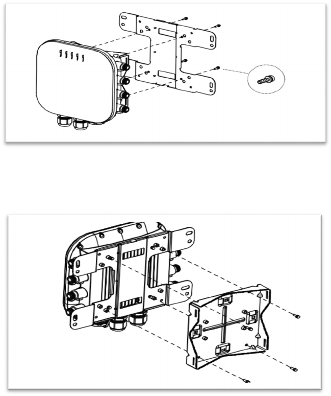
8.9
Attaching a mesh node to a vertical pole
The
Mesh
node
comes
with
two
sets
of
brackets
-
wall
mount
bracket
and
pole
mount
bracket.
Attaching
the
mesh
node
to
a
pole
requires
both
pole
mount
as
well
as
wall
mount
brackets.
The
below
procedures show
how
to
attach
the
Mesh
node
into
a
vertical
pole.
1.
Place
the
lock
and
flat
washer
on
the
four
hex
cap
screws
and
drive
the
screws
to
attach
bracket
to
the
back
of
the
mesh
node.
2.
Drive the four round head screws to attach the pole mount bracket to the wall
mount bracket.
HotPort 8020 Mesh Node Installation Guide
19
3.
Thread the open end of the pole strap through the two tabs on the pole mount
brackets.
4.
Lock
and
tighten
the
pole
strap
to
secure
the
pole
mount
b
racket
to the
pole.
Note:
The
installation
is
correct
if
the
node
does
not
easily
move
from
side
to
side.
Best
practice:
Use a
spray
to
prevent
corrosion
on
the bracket
and
mount
h
ardware.
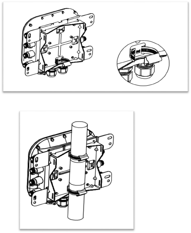
8.10
Attaching a mesh node to a horizontal pole
To
attach the mesh node to a horizontal
pole
procedures
are
same
as
attaching
the
node
to
a
vertical
pole.
Following
picture
shows
the
mesh
node
attached
to
a
horizontal
pole.
HotPort 8020 Mesh Node Installation Guide
20
Note:
The
installation
is
correct
if
the
node
does
not
easily
move
from
side
to
side.
Best
practice:
Use
a
spray
to
prevent
corrosion
on
the
bracket
and
mount
hardware.
HotPort 8020 Mesh Node Installation Guide
21
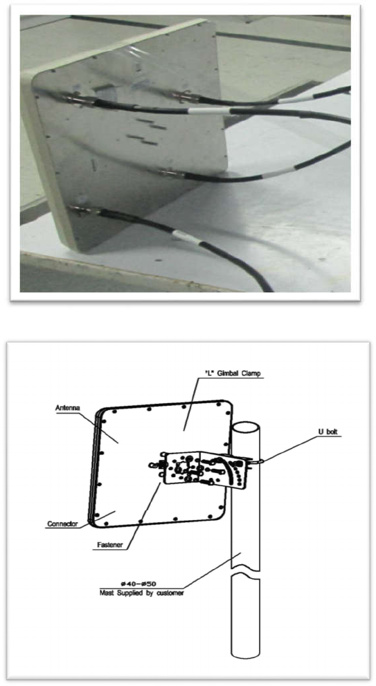
8.11
Panel antenna Assembly
Following
picture
shows
4x4 Panel Antenna installed with RF cable.
Following
picture
shows
the
Installation of Panel Antenna to a vertical pole.
Attach the panel antenna to the antenna bracket
Attach one end of RF cable to the Panel antenna and the other end of RF cable that have lightning
arrestors to the mesh node.
Refer section 8.7 for installation of mesh node and panel antenna assembly process.
HotPort 8020 Mesh Node Installation Guide
22
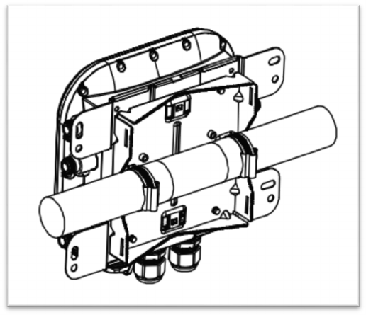
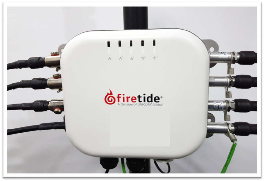
8.12
Mesh node installation with RF cable assembly on a vertical pole.
Front View:
No
t
e
:
Conne
ct
t
he
li
gh
t
n
i
ng
arr
e
st
e
r
of
all
a
n
t
enn
a
po
rts
t
o
p
r
o
t
e
cti
ve
g
r
ound
.
HotPort 8020 Mesh Node Installation Guide
23
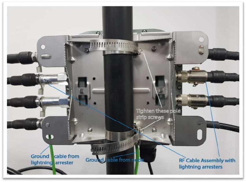
Rear view:
HotPort 8020 Mesh Node Installation Guide
24
9 Trouble shooting
If a mesh nod e does not
operate correctly try these suggestions.
If you recorded the performance of your network when you set it up, you have a
benchmark against which you can compare future performance and you might be
able
to
identify
problem
areas
faster
than
if
you
try
to
diagnose
a new
problem.
Cannot see a mesh node in Web NMS
If you cannot see one or more mesh nodes in FMA, make sure that you set the extended range and
multiple hop feature.
If you can see the head node but no other nodes, then you also might have a configuration problem.
After multiple reboots a mesh node is missing
If a mesh node reboots five times within 10minutes, the mesh node loads the second saved firmware
image.
The previous firmware, if older or different from the firmware of the other mesh nodes in a mesh
network, might not be recognized by the mesh and FMA will not detect the mesh node.
Performance not as expected
If the network performance is not as expected:
Identify re use in your channel plan. If you have no channel reuse in the network, do a spectrum
analysis.
Check for self-interference. For example, the radios in a single device might connect.
Check the frequency plan and make sure that all the radios are configured correctly.
Make sure that each node is connected to the correct devices and nodes.
Determine the total throughput with an end to end test.
Determine the throughput of each link with tests.

HotPort 8020 Mesh Node Installation Guide
25
Resetting an outdoor mesh node to factory default settings
You
can
reset
an outdoor
mesh
node
with
this
procedure.
The
reset
button
is
inside
the console
opening
above the RJ45 Connector.
Caution! When a HotPort mesh node is reset, all configuration information is erased.
For this procedure you need these items:
1
Paperclip, pen, or pencil
2
Adjustable wrench
To reset an outdoor mesh node:
1
Power up the mesh node.
2
Remove the weather proof cover of console / reset port. Use a wrench if the valve is too
tight to remove by hand.
Caution! Do not use pliers to remove the pressure relief valve because you can break it.
3
Press and holdtheresetbuttonwiththepaperclipfor10 seconds until the Power LED changes
the color to amber and blinks.
4
The device reboots, and the LEDs turn to green indicating its operational status.
5
Wait one minute, and then log into WebNMS.
6
Configure the mesh node or apply a previously saved configuration file.
7
Cover the console / reset port with the weather proof cover.
8
Using WebNMS configure the mesh node.
HotPort 8020 Mesh Node Installation Guide
26
10 Weather proof procedures
Cable
connections
become
loose
over
time
because
of
vibration.
Loose
connections let
moisture
contact and erode the interface to a connector. To
prevent performance problems due to
moisture
damage, Firetide
recommends
that
you
use
butyl
mastic
to
make weather proof
all
outdoor
connections.
Butylmastic is a synthetic rubber sealant that you can use to make a connection
weather proof. It
is
slightly sticky
and
stays flexible;
it
bonds
to itself
to make
a
good seal. Butymastic and
a layer
of electrical tape keeps the cable assembly
clean,
dry,
and easy
to change in
the
future.
Note:
To make a strong water tight connection, keep a high level of tension in the butyl mastic when
you stretch it over the cable and connector.
10.1
Tools and materials
To make a weatherproof connection you need the following tools and materials:
Screw driver
Pliers
Utility knife
Vinyl electrical tape
Note:
Vinyl electrical tape between the cable assembly and the mastic tape makes future changes
easier than mastic tape put directly on the cable. Vinyl electrical tape as a cover over the mastic tape
prevents the mastic from melting in hot weather.
Rubber splicing or mastic tape (also known as self-amalgamating, self- sealing, self-fusing, non-
vulcanized tape)
Pencil or wooden dowel for small clearances
Cleaning supplies (if necessary)
Making weatherproof cable to node connections
Y
ou need to make weather proof two connections:
From the antenna cable to the lightning arrester
From the lightning arrester to the node
To make a weather proof cable to node connection:
Gather the tools and materials to do the procedure.
Ensure that the cable and connectors are clean. Clean off oil, water, grease, and dirt before you
continue.
Wrap a layer of electrical tape (sticky side out) over the arrester to node connector and wrap
approximately 1 inch (2.5cm) of cable. Overlap the tape by 40% with each turn.
Repeat for the antenna cable to arrester connection.
HotPort 8020 Mesh Node Installation Guide
27
Note:
To make a watertight connection, keep tension in the butyl mastic when you stretch it over the
cable and connector.
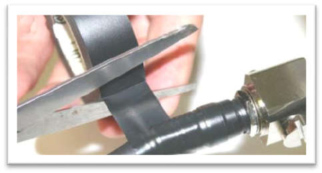
Tightly wrap a layer of mastic tape over the electrical tape. Make a 40% overlap on each turn. Start
from the base of the unit to at least 1inch (2.5 cm) of the cable.
Wrap a layer of electrical tape (smooth side out, sticky side in) over the mastic tape.
Wrap a second layer of electrical tape over the first layer of electrical tape.
The lightning arrestor connections are ready for installation in an outdoor environment.
HotPort 8020 Mesh Node Installation Guide
28
11 Information to User, Purchaser & Installer
11.1
Federal Communication Commission Interference Statement
This equipment has been tested and found to comply with the limits for a class-B digital device, pursuant to part
15 of the FCC Rules. These limits are designed to provide reasonable protection against harmful interference when
the equipment is operated in a commercial environment. This equipment generates, uses, and can radiate radio
frequency energy and, if not installed and used in accordance with the instruction manual, may cause harmful
interference to radio communications.
However, there is no guarantee that interference will not occur in a particular installation. If this equipment does
cause harmful interference to radio or television reception, which can be determined by turning the equipment off
and on, the user is encouraged to try to correct the interference by one of the following measures:
Reorient or relocate the receiving antenna.
Increase the separation between the equipment and receiver.
Connect the equipment into an outlet on a circuit different from that to which the receiver is
connected.
Consult the dealer or an experienced radio/TV technician for help.
FCC Caution:
Any changes or modifications not expressly approved by the party responsible for compliance could
void the user's authority to operate this equipment.
This transmitter must not be co-located or operating in conjunction with any other antenna or transmitter.
Accessories or components to be used with this equipment to use in the system, must comply with the FCC
Part 15.27 special accessories regulations. It is the responsibility of the user to use the needed special
accessories along with the equipment.
Radiation Exposure Statement
This equipment complies with FCC radiation exposure limits set forth for an uncontrolled environment. This
equipment should be installed and operated with minimum distance 51cm between the radiator & your body.
This equipment must be professionally installed. The installer is responsible for adjusting the transmit power
output of the system to assure compliance with FCC Part15 EIRP limits and human radiation safety
regulations. Operating TX Power allowed Power limits is as per FCC 15.407(a).
Professional installation instruction
1.
Installation personal
HotPort 8020 Mesh Node Installation Guide
29
This product is designed for specific application and needs to be installed by a qualified personal who has
RF and related rule knowledge. The general user shall not attempt to install or change the setting.
2.
Installation location
The product shall be installed at a location where the radiating antenna can be kept 51cm from nearby
person in normal operation condition to meet regulatory RF exposure requirement.
3.
External antenna
Use only the antennas which have been approved by the applicant. The non-approved antenna(s) may
produce unwanted spurious or excessive RF transmitting power which may lead to the violation of FCC
limit and is prohibited.
4.
Installation procedure
Please refer to user’s manual for the detail.
5.
Warning
Please carefully select the installation position and make sure that the final output power does not exceed
the limit set force in relevant rules. The violation of the rule could lead to serious federal penalty.