Firmtech FB755AC BLUETOOTH EMBEDDED MODULE User Manual 1
Firmtech co., Ltd BLUETOOTH EMBEDDED MODULE Users Manual 1
Firmtech >
Contents
- 1. Users Manual 1
- 2. Users Manual 2
Users Manual 1
Bluetooth Embedded Module
FB755AC & FB755AS User Guide
Version 1.1
FIRMTECH Co., Ltd.
B-606, Ssangyong IT Twin Tower, Sangdaewon-dong, 442-5
Jungwon-gu, Seongnam-si, Gyeonggi-do, Korea 462-120
Tel : +82-31-719-4812
Fax : +82-31-719-4834
www.firmtech.co.kr

FB755AC & FB755AS User Guide Version 1.1 Revision History
Page 2 / 31
Revision History
Revision Date Change Descriptions
1.0 05-10-2007 - Write a draft
1.1 15-12-2008 - Connecting with Connection WIZARD
- PC Configuration using Config tool

FB755AC & FB755AS User Guide Version 1.1 (C) Copyright FIRMTECH Co., Ltd. 2005
Page 3 / 31
(C) Copyright FIRMTECH Co., Ltd. 2005
All rights reserved
The products and operation descriptions contained herein shall be protected by copyright law.
Any part or whole of products or operation description shall not be copied, reproduced,
translated, nor transformed into readable form by electronic device or machines, without prior
consent in writing by FIRMTECH Co., Ltd.
There might be some misprinting or technical faults in the products and operation description
which are subject to change without prior notice.
FCC Information to User
This equipment has been tested and found to comply with the limits for a Class B digital device,
pursuant to Part 15 of the FCC Rules. These limits are designed to provide reasonable protection
against harmful interference in a residential installation. This equipment generates, uses and can
radiate radio frequency energy and, if not installed and used in accordance with the instructions,
may cause harmful interference to radio communications. However, there is no guarantee that
interference will not occur in a particular installation. If this equipment does cause harmful
interference to radio or television reception, which can be determined by turning the equipment
off and on, the user is encouraged to try to correct the interference by one of the following
measures:
• Reorient or relocate the receiving antenna.
• Increase the separation between the equipment and receiver.
• Connect the equipment into an outlet on a circuit different from that to which the receiver is
con-nected.
• Consult the dealer or an experienced radio/TV technician for help.
Caution
Modifications not expressly approved by the party responsible for compliance could void the
user’s authority to operate the equipment.
FCC Compliance Information : This device complies with Part 15 of the FCC Rules.
Operation is subject to the following two conditions: (1) This device may not cause harmful
interference, and (2) this device must accept any interference received, including interference that
may cause undesired operation
IMPORTANT NOTE:
FCC RF Radiation Exposure Statement:
This equipment complies with FCC RF radiation exposure limits set forth for an uncontrolled
environment. This equipment should be installed and operated with a minimum distance of 20
centimeters between the radiator and your body.This transmitter must not be co-located or
operating in conjunction with any other antenna or transmitter.

FB755AC & FB755AS User Guide Version 1.1 List of Content
Page 4 / 31
List of Content
1 What is Bluetooth?...........................................................................................................................................................5
1.1 Features of Bluetooth ........................................................................................................................................5
1.2 Operation of Bluetooth.....................................................................................................................................5
2 Product Overview .............................................................................................................................................................7
3 Product Components ......................................................................................................................................................8
3.1 FB755AC....................................................................................................................................................................8
3.2 FB755AS ....................................................................................................................................................................8
3.3 PC Interface Kit (Option)..................................................................................................................................8
4 Product Appearance .....................................................................................................................................................10
4.1 FB755AC Dimension.........................................................................................................................................10
4.2 FB755AS Dimension.........................................................................................................................................10
4.3 FB755AC PIN Assign........................................................................................................................................11
4.4 FB755AS PIN Assign ........................................................................................................................................11
5 Interface (Pin Connection) ........................................................................................................................................13
5.1 Without Flow Control......................................................................................................................................13
5.2 With Flow Control.............................................................................................................................................13
5.3 1:N Communication .........................................................................................................................................14
6 PC Interface Board (Jig Board) ...............................................................................................................................15
7 Performance of Products ...........................................................................................................................................17
8 Current Consumption ..................................................................................................................................................18
9 Preliminary Product Components .........................................................................................................................19
10 Connecting the wireless section of Bluetooth .............................................................................................20
10.1 Connecting with Connection WIZARD.................................................................................................20
10.2 Connection with AT commands ..............................................................................................................23
11 How to complete PC Configuration? ................................................................................................................24
11.1 PC Configuration using BTConfig tool ................................................................................................24
11.2 PC Configuration using Serial Communication (Hyper Terminal) Program..................... 27
FB755AC & FB755AS User Guide Version 1.1 1 What is Bluetooth?
Page 5 / 31
1 What is Bluetooth?
1.1 Features of Bluetooth
Objectives of Bluetooth : To Realize Wireless Communication for Short Distance with Low Power
Consumption, High Reliability, and Low Cost.
Frequency in Use: To Use ISM(Industrial, Scientific, Medical) Band which does not require any
permission to use.
- 2.400 – 2.4835 GHz, 79 channels
- 2.465 – 2.4835 GHz, 23 channels (in France)
Transmission Rate : 1Mbps ~ 3Mbps
Transmission Output : 1mW (10m, Class2), 100mW (100m Class1)
Network Configuration : Configured with Master and Slave relation. A Bluetooth unit shall allow
simultaneous connections up to 7 devices (in case of ACL).
Reliability : To Guarantee stable wireless communication even under severe noisy environment
through adopting the technique of FHSS (Frequency Hopping Spread Spectrum).
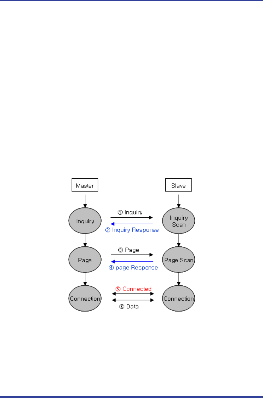
1.2 Operation of Bluetooth
<Feature 1-1 Bluetooth Operation>
Bluetooth operates based on the connection between “Master” and “Slave”.
Masters are simply supposed to do “Inquiry” and “Page”. Slaves are supposed to do “Inquiry
Scan” and “Page Scan”.
If a Master finds a Slave and so “inquiry” is successful, a Slave responds to the Master with its
information.

FB755AC & FB755AS User Guide Version 1.1 1 What is Bluetooth?
Page 6 / 31
Interconnection between the Master and the Slave is achieved only if the information from the
Slave is corresponded with the Master, and the Slave sends data to the Master.

FB755AC & FB755AS User Guide Version 1.1 2 Product Overview
Page 7 / 31
2 Product Overview
FB755AC & FB755AS has been developed to replace the previous RS232 Cable system with wireless
communication system to use.
Major Features of FB755AC & FB755AS
1. Bluetooth Specification 2.0 Support
2. Bluetooth Piconets(Point to Multipoint) are configurable up to(max 1:7)
3. Easily applicable to the Product with 12Pins Header type
4. Support AT Command, and capable to control FB755AC & FB755AS by using AT Command.
5. Easy to connect to use with Bluetooth PDA, Bluetooth USB Dongle, etc.
6. Provides the most compact size among Class 1 EDR.
7. Simply support the function of Bluetooth Firmware Update
8. Stable Data Transmission / Receipt
※ We request the new users of FB755AC & FB755AS to read the information on this description
carefully before they start to use the products.
FB755AC & FB755AS User Guide Version 1.1 3 Product Components
Page 8 / 31
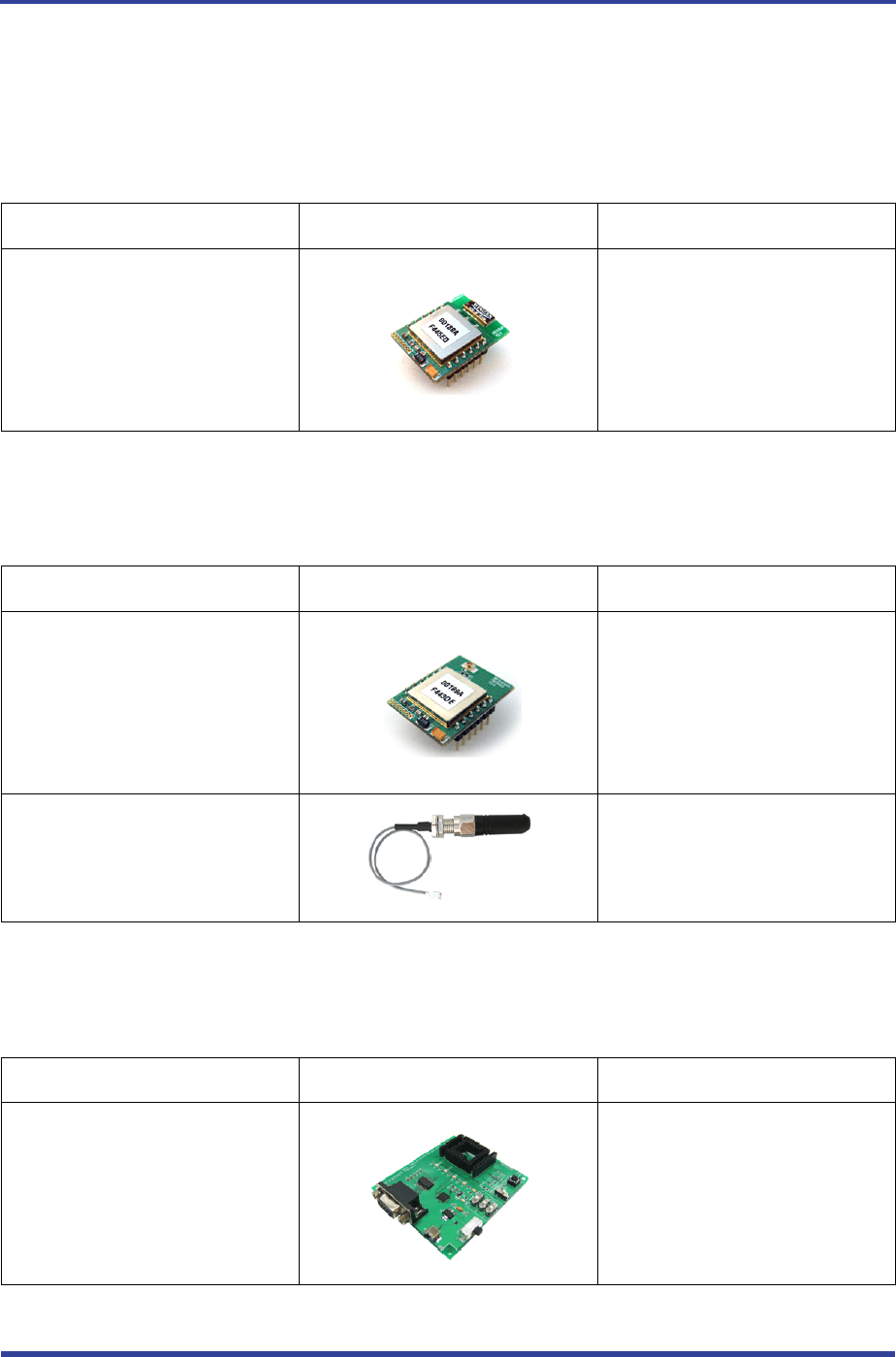
3 Product Components
3.1 FB755AC
MODEL PICTURE Q’TY (EA)
FB577AC
(On-board chip antenna)
1
<Table 3-1 Basic Components of FB755AC>
3.2 FB755AS
MODEL PICTURE Q’TY (EA)
FB755AS
1
FBA001DAL
FBA015ACL
1
1
<Table 3-2 Basic Components of FB755AS>
3.3 PC Interface Kit (Option)
MODEL PICTURE Q’TY (EA)
FBZx5xXX
(Interface Board)
1

FB755AC & FB755AS User Guide Version 1.1 3 Product Components
Page 9 / 31
FBA180SC
(Serial extension cable)
1
FBA100UC
(USB extension cable) 1
FBA001PO
(DC Power Adapter)
1
<Table 3-3 Components of PC Interface Kit>
※ If you find any of above components is defective, or not included in the package, please contact the seller
you purchased.
FB755AC & FB755AS User Guide Version 1.1 4 Product Appearance
Page 10 / 31
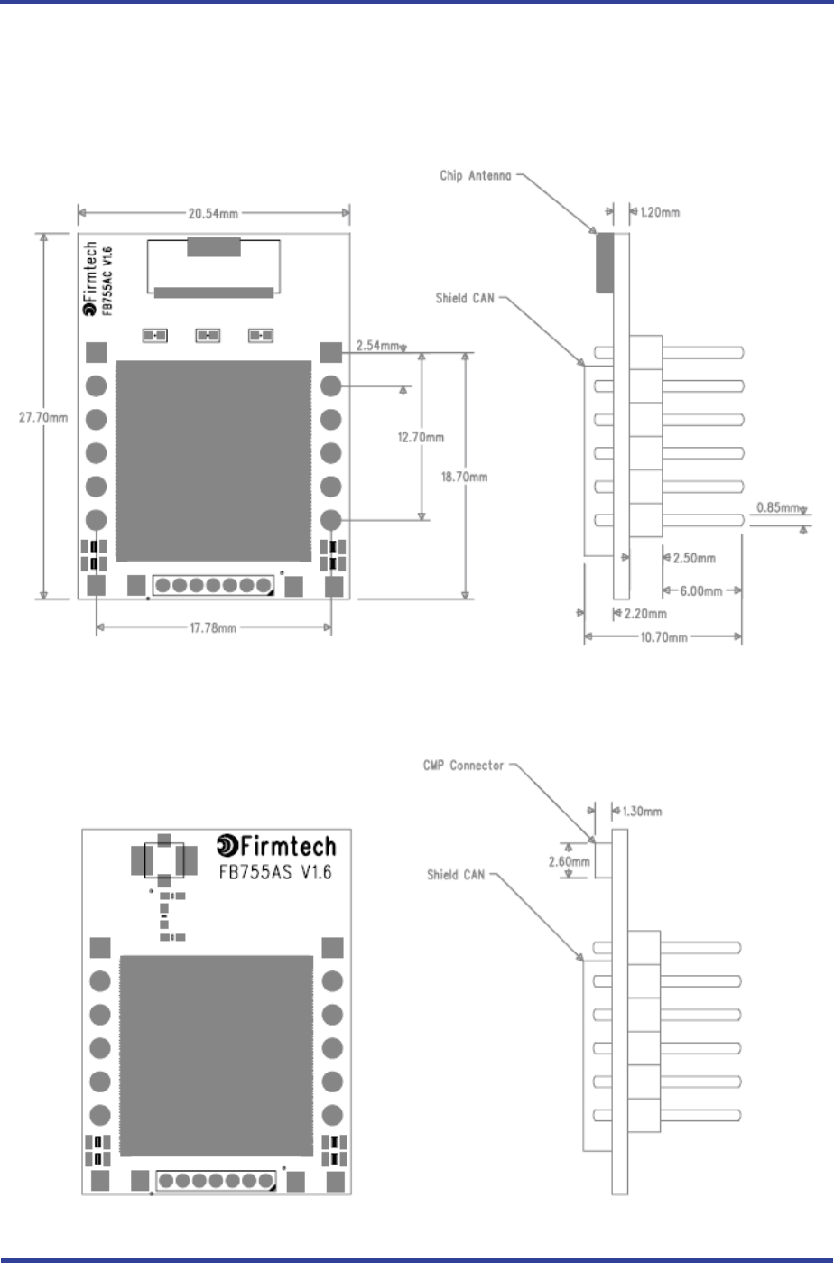
4 Product Appearance
4.1 FB755AC Dimension
<Figure 4-1 FB755AC Dimension>
4.2 FB755AS Dimension
<Figure 4-2 FB755AS Dimension>
FB755AC & FB755AS User Guide Version 1.1 4 Product Appearance
Page 11 / 31
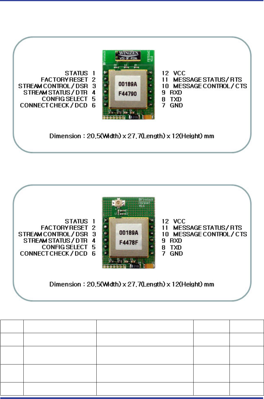
4.3 FB755AC PIN Assign
<Figure 4-3 FB755AC PIN Assign>
4.4 FB755AS PIN Assign
<Figure 4-4 FB755AS PIN Assign>
No. Name of Signal Features I / O Level
1 STATUS STATUS LED Output TTL
2 FA SET Factory Reset
Go back default setting Input TTL
Pull-up
3 STREAM_CONTROL
UART_DSR
1:N – Stream Control
1:1 – UART Data Set Ready Input TTL
4 STREAM_STATUS 1:N – Stream Status Output TTL

FB755AC & FB755AS User Guide Version 1.1 4 Product Appearance
Page 12 / 31
UART_DTR 1:1 – UART Data Terminal Ready
5 CONFIG_SELECT Configuration Select Input TTL
Pull-down
6 CONNECT_CHECK
UART_DCD
1:N – Connect Check
1:1 - UART Data Carrier Detect Output TTL
7 GND Ground
8 UART_TXD UART Transfer Data
Data output Output TTL
9 UART_RXD UART Received Data
Data Input Input TTL
10 MESSAGE_CONTROL
UART_CTS
1:N – Message Control
1:1 - UART Clear To Send Input TTL
11 MESSAGE_STATUS
UART_RTS
1:N – Message Status
1:1 - UART Ready To Send Output TTL
12 VSUP 3V3 for RF circuit (Vcc) Input
<Table 4-1 Pin Description>
- Hard Reset (Factory Reset)
When the CONFIG_SELECT (No 5 PIN) is HIGH (Pull-up condition), turn the power ON (PC-Configuration
Mode). And then input LOW signal (0 Volt) to FA_SET (No 2 PIN) for more then 2 seconds for the factory
reset.
- STATUS port
To be used to monitor the status of FB755AC & FB755AS.
To keep LOW(0V) when the two devices are communicable since the connection between wireless range is
smoothly made.
In standby mode for connection with Bluetooth, or connection trial, or searching for around Bluetooth device
will repeat LOW and HIGH.
- UART_CTS, UART_RTS, UART_DTR, UART_DSR
When the flow control is not used, non connection will not affect the operation of FB755AC & FB755AS.
- STREAM_CONTROL, STREAM_STATUS, MESSAGE_CONTROL, MESSAGE_STATUS
The connection is necessarily required for 1:N communication. For 1:1 communication, don’t need to connect.
- CONNECT_CHECK / UART_DCD
CONNECT_CHECK is used for 1:N communication.
In 1:N communication, if all connection is successful, CONNECT_CHECK (DCD) in SLAVE is outputted LOW
signal. However, if one or more of connections is disconnected, DCD in SLAVE will be outputted HIGH signal.
(Default DCD Output : HIGH)
FB755AC & FB755AS User Guide Version 1.1 5 Interface (Pin Connection)
Page 13 / 31
5 Interface (Pin Connection)
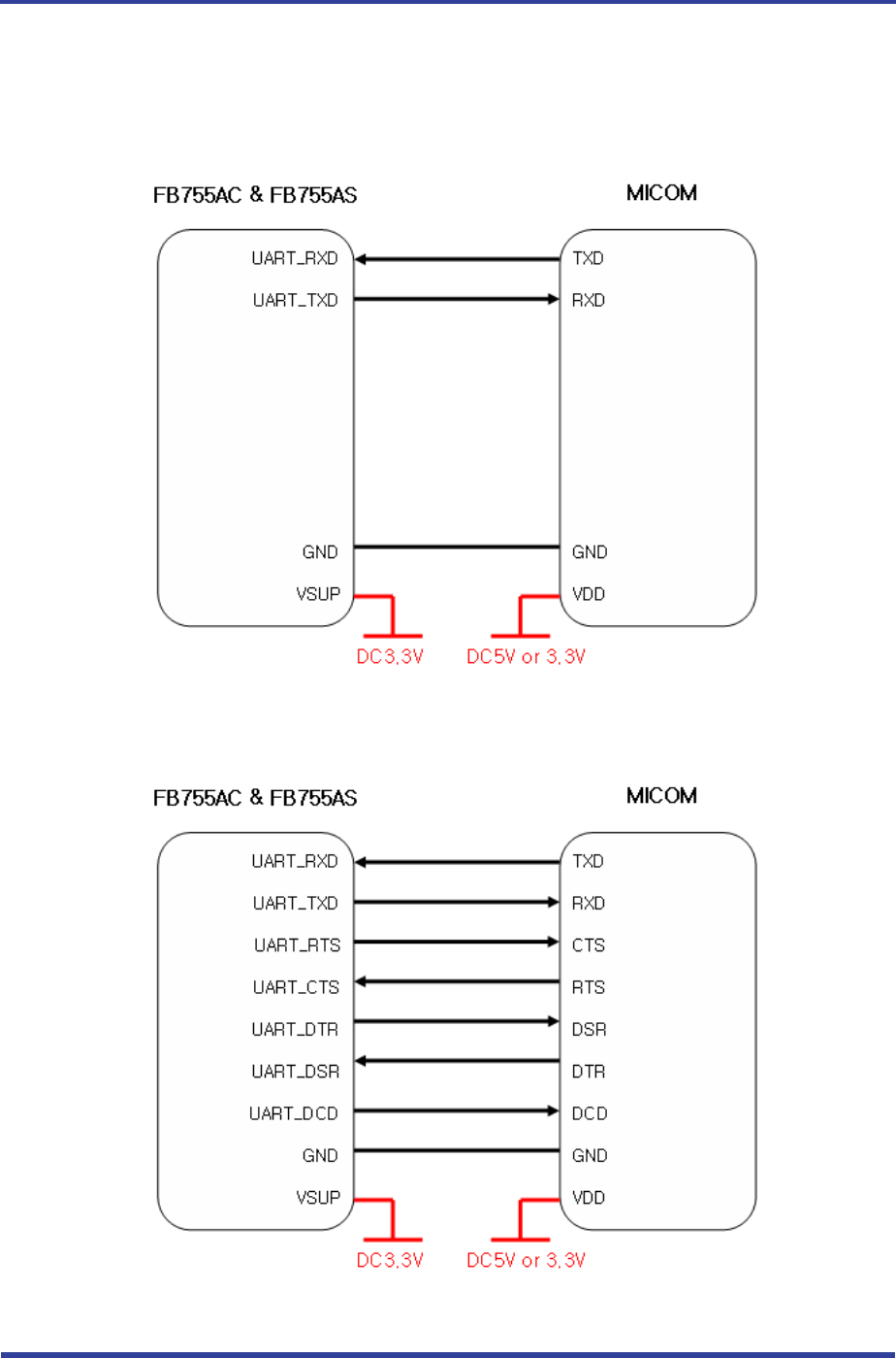
5.1 Without Flow Control
<Figure 5-1 Pin Connection without Flow Control>
5.2 With Flow Control
<Figure 5-2 Pin Connection Diagram with Flow Control>
FB755AC & FB755AS User Guide Version 1.1 5 Interface (Pin Connection)
Page 14 / 31
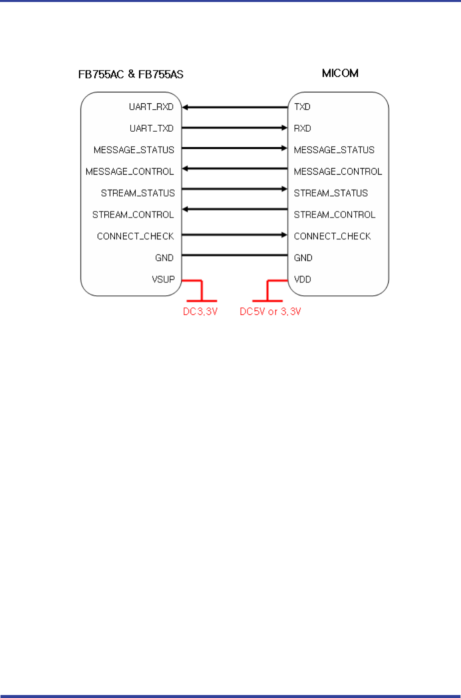
5.3 1:N Communication
<Figure 5-3 Pin Connection Diagram in 1:N Communication>
FB755AC & FB755AS User Guide Version 1.1 6 PC Interface Board (Jig Board)
Page 15 / 31
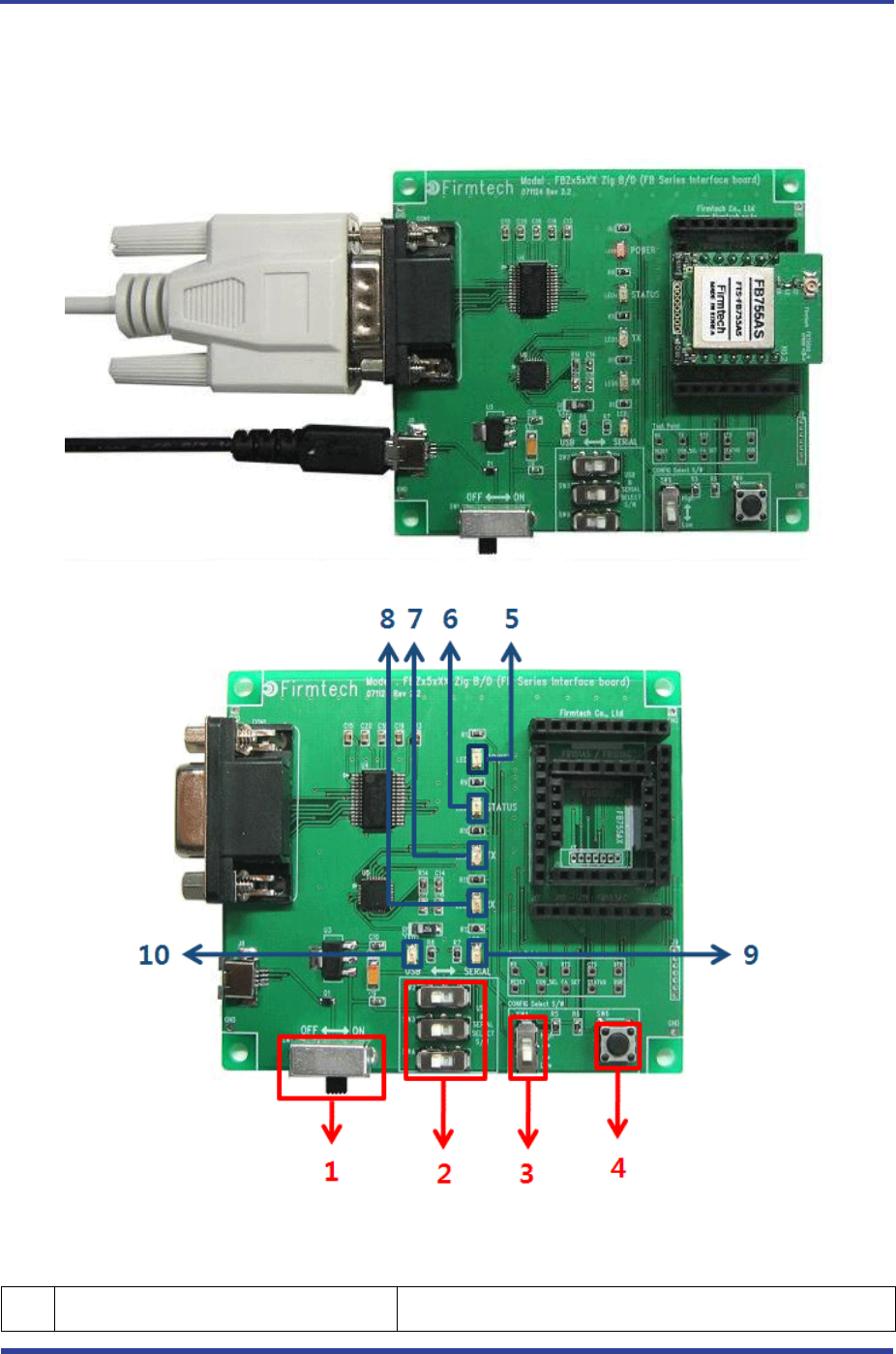
6 PC Interface Board (Jig Board)
<Figure 6-1 FB755AX Interface Board(Jig Board)>
No. Title Description

FB755AC & FB755AS User Guide Version 1.1 6 PC Interface Board (Jig Board)
Page 16 / 31
1 Power ON/OFF Switch ON/OFF the electric power of interface board.
2 USB/RS232 Interface Selection Switch The switch for selection of communication in USB/RS232
(The 3 switches shall be set in same direction.)
3 PC Configuration/Operation Selection
Switch
The switch for selection of bluetooth activation or changing
the setting value stored in FB755
ON – PC Configuration
OFF – Bluetooth Operation
4 FASET Switch
The switch for changing the environment setting value of
FB755 to the factory setting value.
The procedures to make the FASET are as followings.
1. Change the environment setting / bluetooth action
selection switch to ON.
2. Power ON
3. Press the FASET switch more than 2 seconds.
5 POWER LED LED to check the power supply condition
6 STATUS LED LED to check the action of FB755
7 TX LED LED to check the data output condition of FB755
8 RX LED LED to check the data input condition of FB755
9 SERIAL INTERFACE LED LED to check whether the communication interface is RS-
232
10 USB INTERFACE LED LED to check whether the communication interface is USB
<Table 6-1 Interface Board Description>

FB755AC & FB755AS User Guide Version 1.1 7 Performance of Products
Page 17 / 31
7 Performance of Products
No. Part Specification
1 Bluetooth Spec. Bluetooth Specification 2.0 Support
2 Communication distance 100 M
3 Frequency Range 2.4 GHz ISM Band
4 Sensitivity -83dBm (Typical)
FB755AC 12dBm(Typical)
5 Transmit Power
FB755AS 12dBm(Typical)
FB755AC 27.7 x 20.6 mm
6 Size
FB755AS 27.7 x 20.6 mm
7 Support Bluetooth Profile SPP (Serial Port Profile)
8 Input Power 3.3V
9 Current Consumption 100 mA (Max)
Operating -20℃ ~ 50℃
10 Temperature
Limit Operating -30℃ ~ 80℃
11 Communication Speed 1,200bps – 230,400bps
FB755AC Chip Antenna
12 Antenna
FB755AS Helical Antenna
13 Interface UART (TTL Level)
14 Flow Control RTS, CTS, DTR, DSR support
<Table 7-1 FB755AS & FB755AC Performance>

FB755AC & FB755AS User Guide Version 1.1 8 Current Consumption
Page 18 / 31
8 Current Consumption
Current Consumption (mA)
Status
MIN MAX AVG
Standby 3 12 8
Inquiry scan & Page scan (Slave) 6 51 28
Page scan (Slave) 6 21 9
Inquiry (Master) 66 69 67
Slave 27 39 29
Connected
Master 9 21 12
Slave 33 42 37
Data Transmission
Master 30 39 36
Slave 27 42 35
Data Reception
Master 30 42 37
Slave 36 42 39
Data Transmission/Reception
Master 36 45 40
Slave 6 18 10
Power save
Master 5 18 10
<Table 8-1 Current Consumption>
TEST CONDITIONS
Baud Rate : 9600 bps, Input Voltage : DC 5V
The power consumption will change depending on transmission speed and volume of data.

FB755AC & FB755AS User Guide Version 1.1 9 Preliminary Product Components
Page 19 / 31
9 Preliminary Product Components
The preliminary value of product is set as on the <Table 9-1>.
Please be sure of basic set value and so on before using the product.
Type Set Value
Device Name FB755vx.x.x
Pin Code (Pass key) BTWIN
Uart (baud rate-data bit-parity bit-stop bit) 9600-8-N-1
ROLE SLAVE
Connection Mode MODE4 (AT command)
Operation Mode MODE0 (1:1 communication)
Debug Char 0x02
<Table 9-1 Preliminary Configuration Setting Value for FB755AC & FB755AS>
To change the configuration set value of FB755AC & FB755AS, connect FB755AC & FB755AS to the PC using
the PC Interface board then, you may change using the PC software (such as Window Hyper Terminal,
FIRMTECH’s PC configuration program). With MICOM, you may change the set value by using AT command.
Note :
For details on the setting change, please refer to 11 How to complete PC Configuration.
FB755AC & FB755AS User Guide Version 1.1 10 Connecting the wireless section of Bluetooth
Page 20 / 31
10 Connecting the wireless section of Bluetooth
In order for Bluetooth devices to transmit data to each other, the wireless section of Bluetooth should be
connected to each other. To connect the wireless section, you should set each role for each device, one for a
MASTER, another for a SLAVE. It takes about 1~10 sec that a Master is connected to a Slave.
The connection can be done in use of AT command or connection can be set in use of connection WIZARD
because the initial connection mode of FB755AC & FB755AS is MODE4 (AT Command).
The following contents will be processed under the assumption that the FB755AC & FB755AS are connected
to the interface Board (Jig Board).
※ We will use 2 FB755AC & FB755AS and MS Windows in describing procedures.
10.1 Connecting with Connection WIZARD
※ The connection WIZARD can not be used if the DEBUG Char is set to 0x00. Please refer to the details
of environment setting in Appendix A for further details.
(1) Connect the interface board of the first FB755AC & FB755AS to the serial port of PC and switch ON.
(The selection switch of environment setting/bluetooth shall be in OFF.)
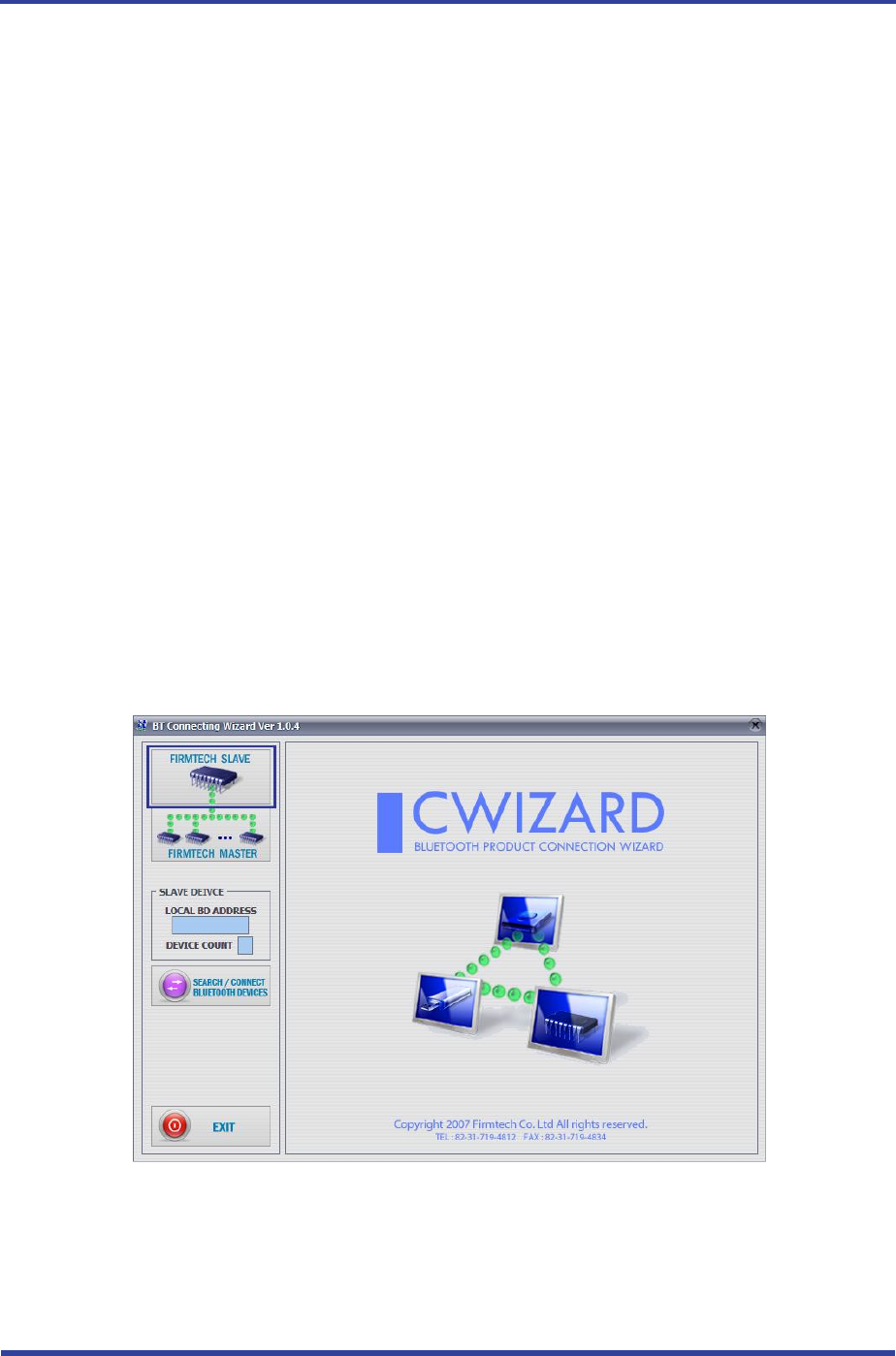
(2) Execute C-Wizard Program.
<Figure 10-1 Connection Wizard Step 1>
(3) Click FIRMTECH SLAVE Set-up button (<Figure 10-1> Blue borders)
FB755AC & FB755AS User Guide Version 1.1 10 Connecting the wireless section of Bluetooth
Page 21 / 31
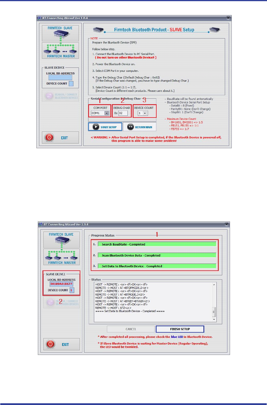
1 COM PORT : Select Serial port of PC connected a product.
2 DEBUG CHAR : Default is 0x02. (Refer to the appendix A about PC Configuration)
3 DEVICE COUNT : Select number of devices to be connected. (Default 1)
<Figure 10-2 Connection Wizard Step 2>
(4) Click the Set-up Start Button(<Figure 10-2> Blue borders) after setting each values in blanks
(<Figure 10-2> Red borders N.1 - Com Port connected to FB755AX, N.2 - 0x02, N.3 - 1)
1 Procedures: procedures of Device Set-up.
2 SLAVE Device value: It shows values if the SLAVE Set-up is completed (optional)
<Figure 10-3 Connection Wizard Step 3>
FB755AC & FB755AS User Guide Version 1.1 10 Connecting the wireless section of Bluetooth
Page 22 / 31
(5) Status Display of Procedures(<Figure 10-3>N. 1 red borders) turns red into green after Set-up is
completed. Click the OK button if the blank of SLAVE Device Value is filled. (<Figure 10-3>N. 2 red
borders)
(6) Check the blinking of status LED on interface board.
(7) Remove the interface board of the 1st FB755AC& FB755AS from the serial port of PC. (On the state
of power ON)
(8) Connect the interface board of the second FB755AC & FB755AS to the serial port of PC and switch
ON. (The selection switch of environment setting/bluetooth shall be in OFF.)
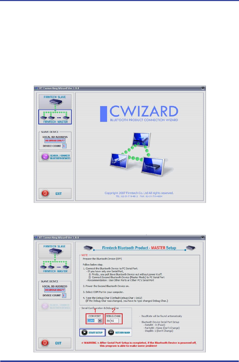
<Figure 10-4 Connection Wizard Step 4>
(9) Click the FIRMTECH MASTER Set-up (<Figure 10-4> Blue borders) Button
FB755AC & FB755AS User Guide Version 1.1 10 Connecting the wireless section of Bluetooth
Page 23 / 31
1 COM PORT : Select the Serial port of PC connected a product
2 DEBUG CHAR : Default is 0x02. (Refer to the appendix A about PC Configuration)
<Figure 10-5 Connection Wizard Step 5>
(10) Click Set-up Start (<Figure 10-5> blue borders) button after setting each value (<Figure 10-5> red
borders N.1 - Com Port connected to FB755AX, N.2 - 0x02) in blanks.
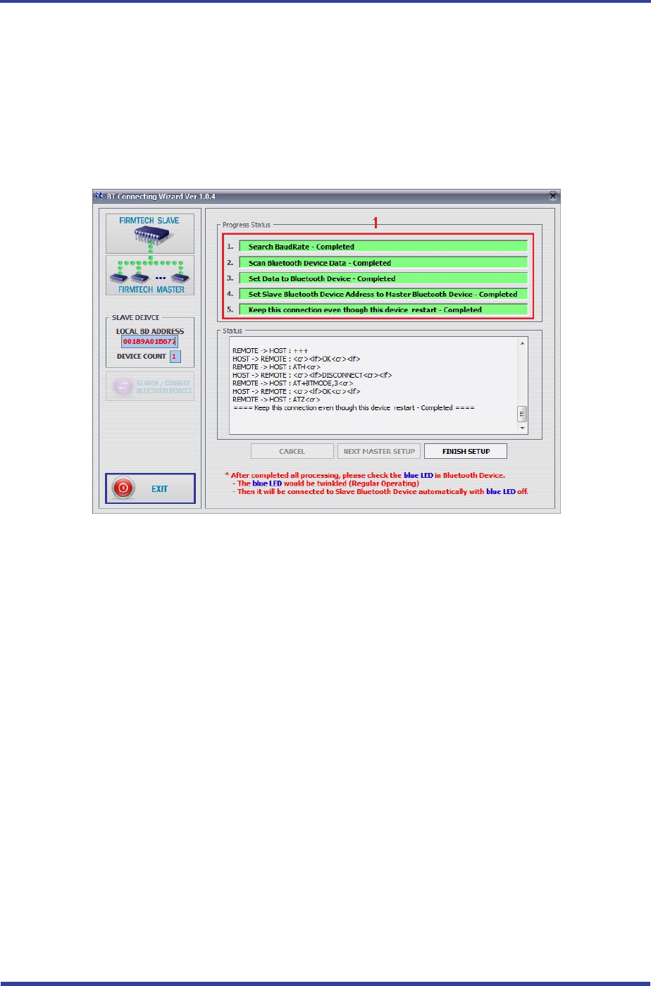
<Figure 10-6 Connection Wizard Step 6>
(11) If the Status Display of Procedures (<Figure 10-6> N.1 red borders) turns red into green,
Connection Set-up is completed. With Clicking the End button(<Figure 10-6> Blue borders), finish
the C-Wizard
10.2 Connection with AT commands
The serial communication program is necessary to connect with AT commands.
The setting is available using the hyper terminal offered by Windows and refer to the following “11.2.1
Execution of hyper terminal” to set hyper terminal.
Refer to the “4. How to use AT commands” of “Appendix B – AT Command Language with Detailed
Description and Usage” to use the AT command.
FB755AC & FB755AS User Guide Version 1.1 11 How to complete PC Configuration?
Page 24 / 31
11 How to complete PC Configuration?
The following PC Configuration shall be explained on the assumption that FB755AC & FB755AS is connected
with PC Interface Board(Jig board). If it is connected to MICOM, then you can change the set value by using
AT command language with reference to Attachment AT command language.
Components for PC Configuration
- FB755AC & FB755AS module
- PC Interface Kit
The PC Configuration could be processed with two significant ways.
First one is to use Config tool provided by FIRMTECH Co., Ltd.
Second one is to use serial communication program (Hyper Terminal, minicom) providing OS.
The respective way of setting is as follows.
11.1 PC Configuration using BTConfig tool
(1) Connect FB755AX to PC Interface Board, then connect to COM port(Serial port) of PC.
(2) Set the environment setting/bluetooth action selection switch (the 3rd switch in <Fig 6-1>) on PC
interface board and switch on
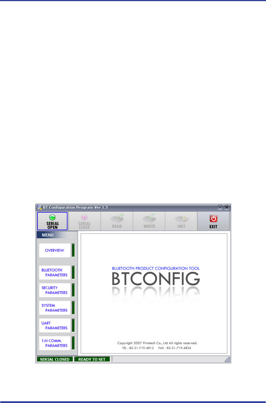
<Figure 11-1 BTConfig tool initialization>
(3) Execute BTConfig tool after connect FB755AX to serial port of PC.
(4) Click “SERIAL OPEN” button. (<Figure 11-1> blue borders)
FB755AC & FB755AS User Guide Version 1.1 11 How to complete PC Configuration?
Page 25 / 31
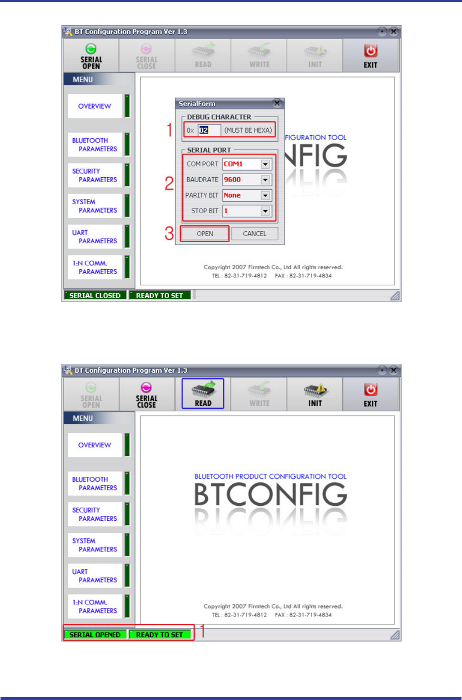
1 DEBUG CHARACTER : Default is 0x02. (refer to the appendix A about PC Configuration)
2 SERIAL PORT : COM PORT proper port, BAUDRATE 9600, PARITY BIT None, STOP BIT 1
<Figure 11-2 BTConfig tool Serial connection>
1 SERIAL OPENED, READ TO SET : BTConfig tool and communication status of products.
<Figure 11-3 BTconfig tool connection>
FB755AC & FB755AS User Guide Version 1.1 11 How to complete PC Configuration?
Page 26 / 31
(5) If the <Figure 11-2> comes up, set each blank (Red borders N.1~2) to (COM PORT – Port
connected to FB100AS, BAUDRATE – 9600, PARITY BIT – None, STOP BIT – 1). After the set-up, click
the OPEN button (Red borders N.3), then Serial Connection and Ready To Set (Red borders N.1)
parts become green as shown on <Figure 11-3>
If they don’t become green, check the COM PORT and execute BTConfig tool once again.
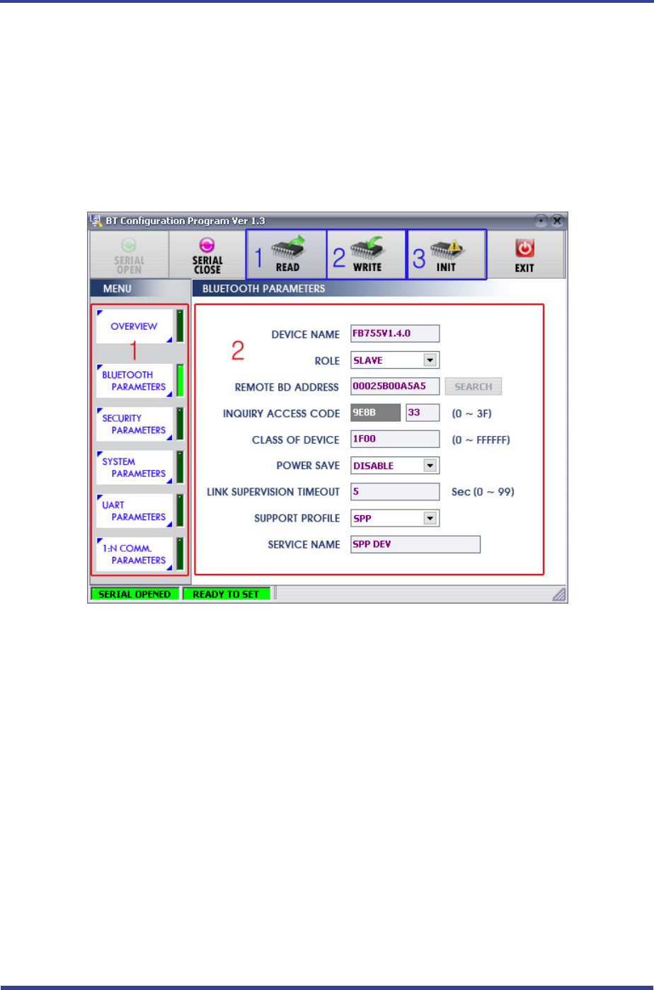
(6) If click the READ button (blue borders) as shown on <Figure 11-3> after BTConfig tool is connected
to products, MENU Buttons (<Figure 11-4> red borders N.1) are activated.
1 BLUETOOTH PARAMETERS: Set-up Group Button
2 Set-up window: change Set-up Groups and values
1 READ button: read set values. (READ should be done after BTConfig tool is connected to products at the
very first initialization.)
2 WRITE button: Save set values. (Serial port is automatically completed after saving.)
3 INIT button: Reset all the set values to Factory fix points.
<Figure 11-4 BTConfig tool Set-up>
(7) If you select any PARAMETERS(<Figure 11-4> red borders N.1), the window for Value Check and
Set-up comes up on the right
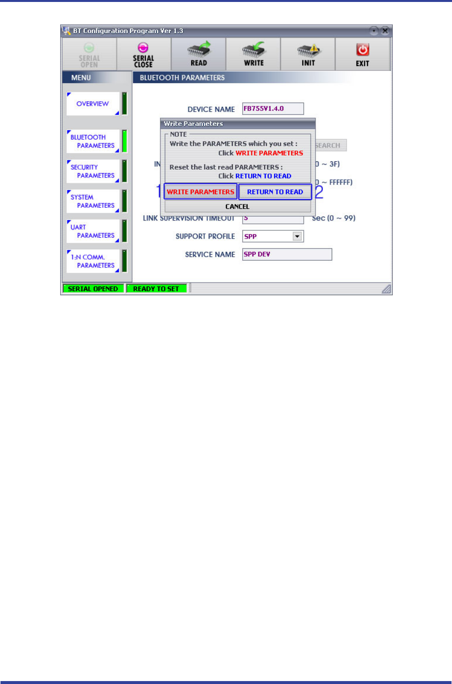
(8) Save the set values by clicking the WRITE button after Set-up completed.
FB755AC & FB755AS User Guide Version 1.1 11 How to complete PC Configuration?
Page 27 / 31
1 WRITE PARAMETERS: Save the currently set values.
2 RETURN TO READ: Set to the initial value.
<Figure 11-5 BTConfig tool WRITE>
Note :
Please refer to the appendix A of PC Configuration for the detailed description.
11.2 PC Configuration using Serial Communication (Hyper Terminal)
Program
11.2.1 To Execute Hyper Terminal
To set up PC Configuration using Hyper Terminal, following procedures shall be performed prior to the
power is being supplied after the FB755AX is connected to the PC.
To set up PC Configuration, the Serial Communication Program is required. We will use Hyper Terminal
in describing the procedures.
(1) Set the PC Configuration/Operation Selection Switch (<Figure 6-1> N 3 Switch) on the PC Interface
Board(Jig Board) ON
FB755AC & FB755AS User Guide Version 1.1 11 How to complete PC Configuration?
Page 28 / 31
<Figure 11-6 Hyper Terminal Set up Window 1>
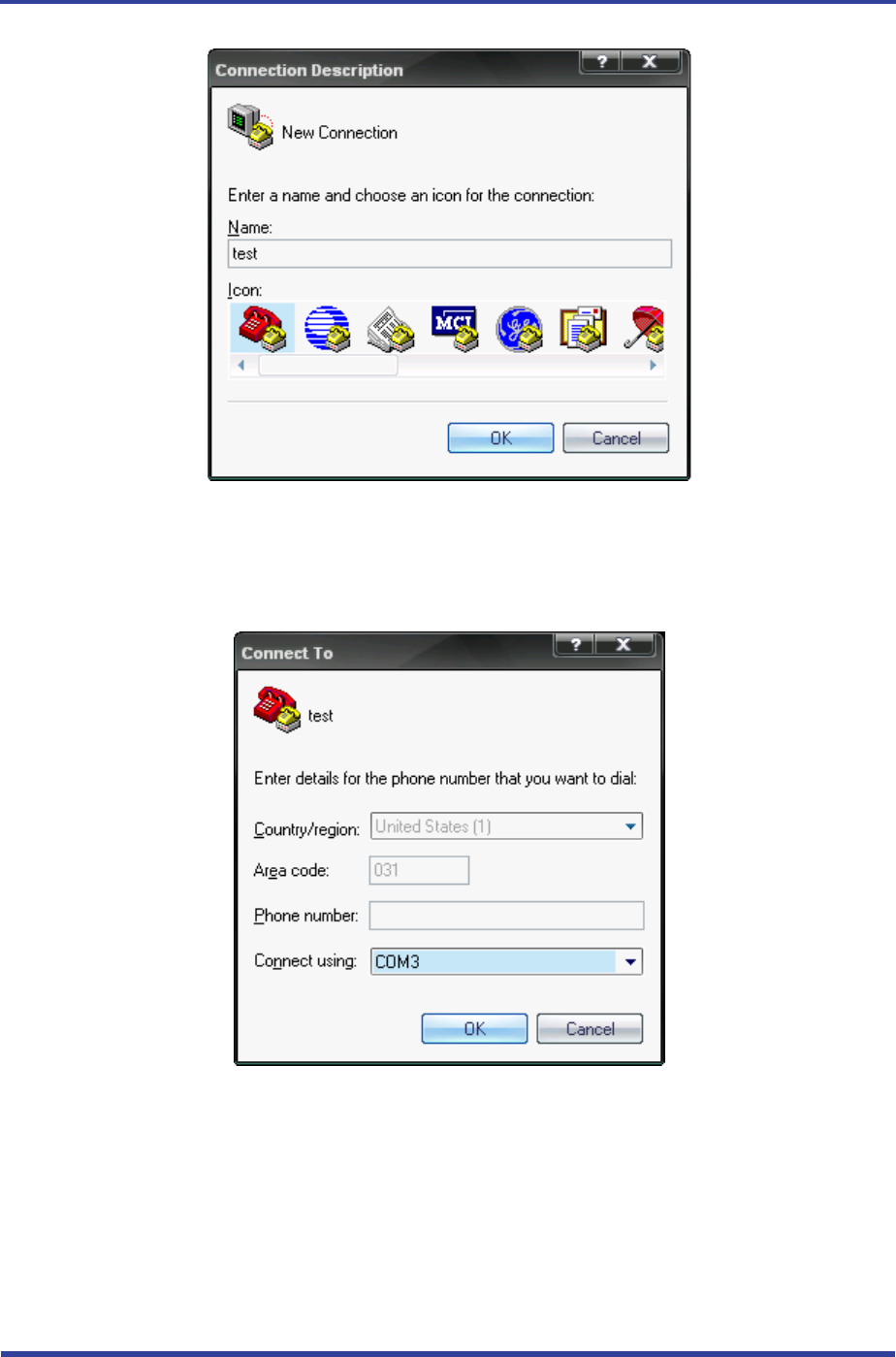
(2) Execute in the order of [start][All Programs][Accessories][Communications][Hyper
Termi nal ], then connection window will appear on which enter appropriate name and click.
<Figure 11-7 Hyper Terminal Set up Window 2>
(3) When the <Figure 11-7> comes up, select the COM port connected to FB755AX, and clicks the OK
button.
FB755AC & FB755AS User Guide Version 1.1 11 How to complete PC Configuration?
Page 29 / 31
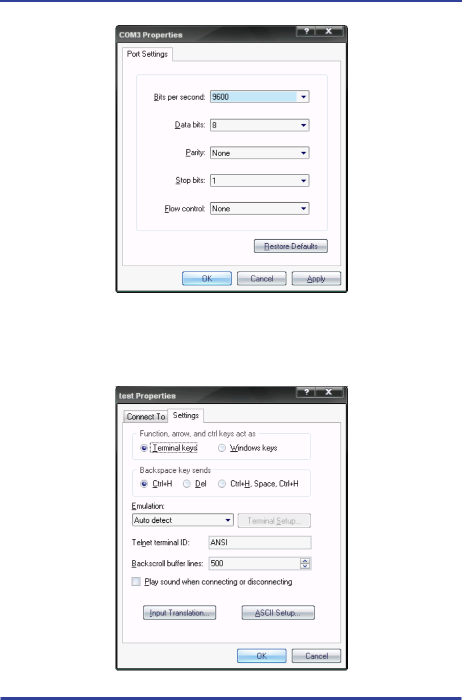
<Figure 11-8 Hyper Terminal Set up Window 3>
(4) When Registration Information Window comes up as on <Figure 11-8>, select Bit per second :
9600, Data bit : 8, Parity : none, Stop bit : 1, Flow control : none, which will execute Hyper
Terminal.
<Figure 11-9 Hyper Terminal Set Up Window 4>
FB755AC & FB755AS User Guide Version 1.1 11 How to complete PC Configuration?
Page 30 / 31
(5) Basically, the Hyper Terminal does not show the entered character. To make sure of the entered
character, select [File][Properties] on the Menu, then registration information window will appear
shown as on <Figure 12-9>, click the ASCII Setup button.
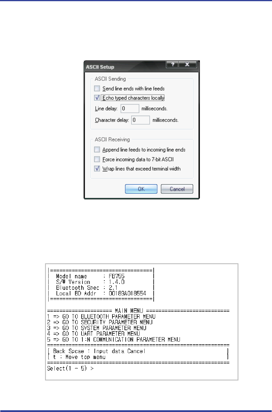
<Figure 11-10 Hyper Terminal Set Up Window 5>
(6) As shown on <Figure 11-10>, Check “Echo typed characters locally” and come out pressing the
acknowledge button. Now the Hyper Terminal program setting procedure is completed to use PC
Configuration.
(7) If the power is on interface board, the menu like the <Fig. 11-11> si printed on the hyper terminal.
<Figure 11-11 Pc Configuration Menu>
11.2.2 How to Use PC Configuration Menu

FB755AC & FB755AS User Guide Version 1.1 11 How to complete PC Configuration?
Page 31 / 31
The user may select the menu to change by selecting the given number in front of the left end menu.
For example : To change “GO TO BLUETOOTH PARAMETER MENU”, enter : [1][Enter]
Note :
At <Figure 11-11> condition, Pressing Reset button for more than 2 seconds will reset all the
configured values to the initial status (factory preset status).
Following is the order to use the menu.
(1) The execution will only be executed by pressing the “Enter” key.
(2) The small character “t” will always move to be positioned at upper side of the menu.
(3) To move menu, use the number in the end of left side. Please be sure to “Enter” key upon
completion of input.
(4) “←” key is used to delete the entered character currently.
(5) If the entered character is unreadable or is not supported at the appropriate menu, “Retry >”
message will be output.
(6) If the input message is more than 12 characters, “Overflow buffer” message will be output and then
“Retry >” message appeared as well.
Upon completion of all PC configuration, turn off the Interface Board, switch the PC
Configuration/Operation Selection switch OFF, and turn the power ON, which will start the Bluetooth to
operate normally.
Note :
Please refer to Appendix A PC Configuration for the detailed description on the configuration
value.