Firmtech FB755AC BLUETOOTH EMBEDDED MODULE User Manual 1
Firmtech co., Ltd BLUETOOTH EMBEDDED MODULE Users Manual 1
UserManual.wiki
>
Firmtech
>
FB755AC User Manual
>
Users Manual 1
Contents
1.
Users Manual 1
2.
Users Manual 2
Users Manual 1
Navigation menu
Upload a User Manual
Namespaces
Wiki Guide
HTML
PDF
Info
Views
User Manual
Discussion / Help
Navigation

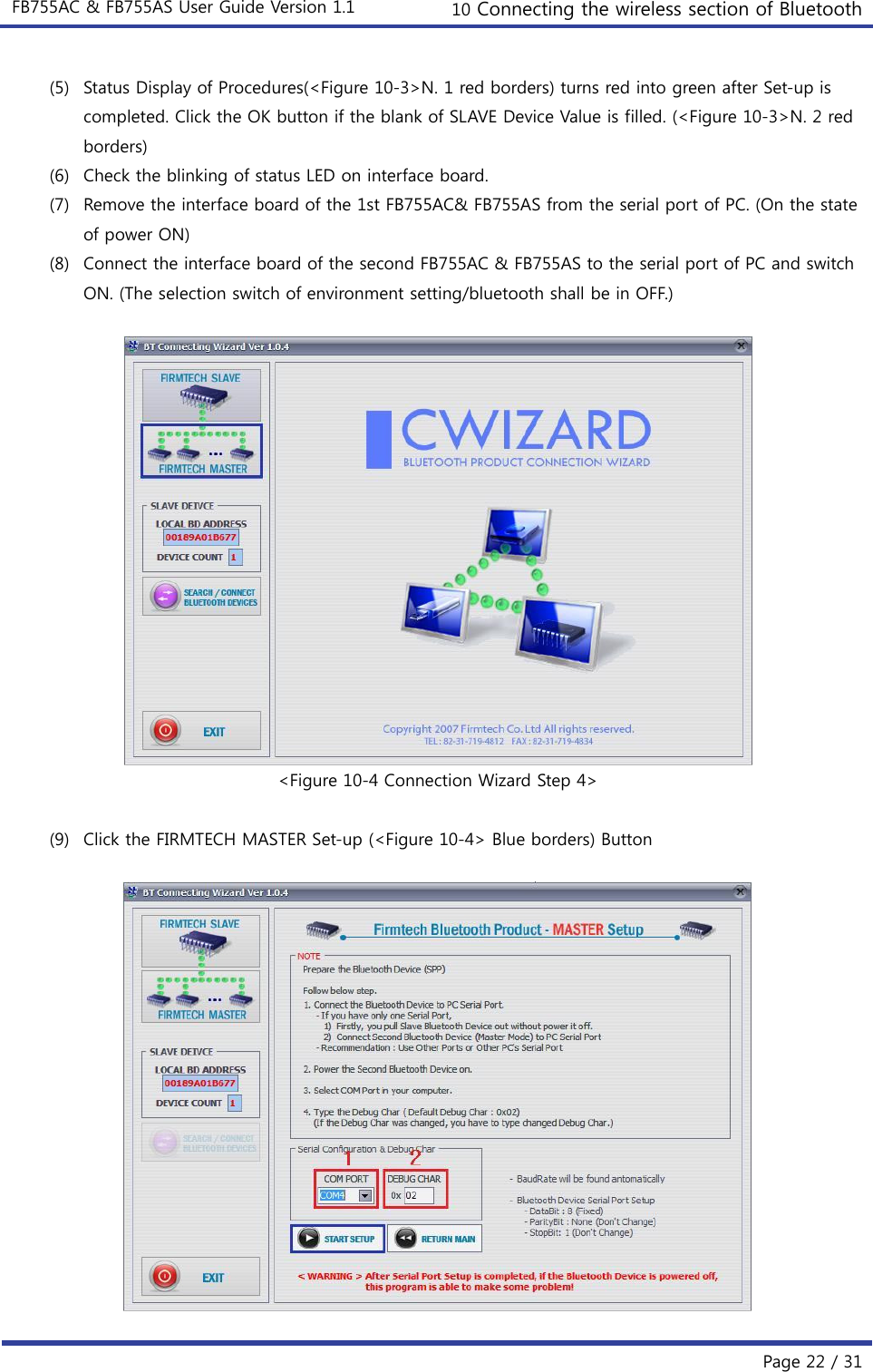
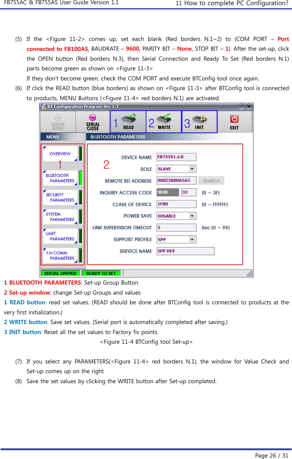
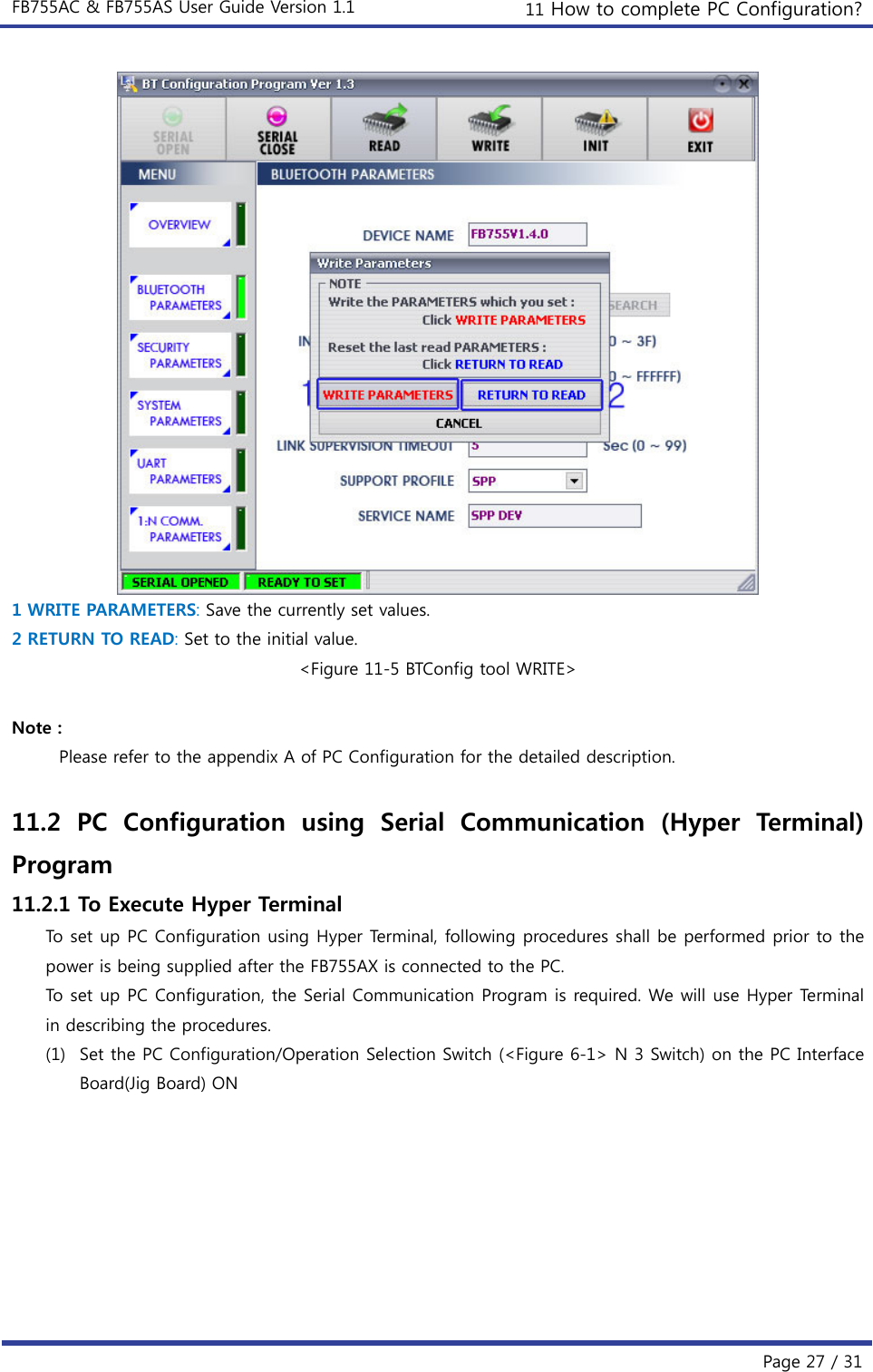
![FB755AC & FB755AS User Guide Version 1.1 11 How to complete PC Configuration? Page 28 / 31 <Figure 11-6 Hyper Terminal Set up Window 1> (2) Execute in the order of [start][All Programs][Accessories][Communications][Hyper Termi nal ], then connection window will appear on which enter appropriate name and click. <Figure 11-7 Hyper Terminal Set up Window 2> (3) When the <Figure 11-7> comes up, select the COM port connected to FB755AX, and clicks the OK button.](https://usermanual.wiki/Firmtech/FB755AC.Users-Manual-1/User-Guide-1315325-Page-28.png)
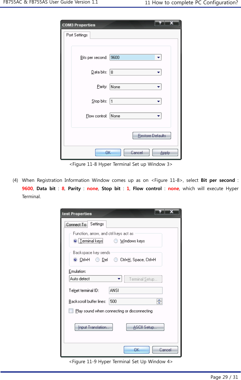
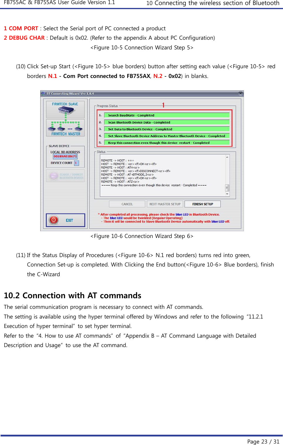
![FB755AC & FB755AS User Guide Version 1.1 11 How to complete PC Configuration? Page 30 / 31 (5) Basically, the Hyper Terminal does not show the entered character. To make sure of the entered character, select [File][Properties] on the Menu, then registration information window will appear shown as on <Figure 12-9>, click the ASCII Setup button. <Figure 11-10 Hyper Terminal Set Up Window 5> (6) As shown on <Figure 11-10>, Check “Echo typed characters locally” and come out pressing the acknowledge button. Now the Hyper Terminal program setting procedure is completed to use PC Configuration. (7) If the power is on interface board, the menu like the <Fig. 11-11> si printed on the hyper terminal. <Figure 11-11 Pc Configuration Menu> 11.2.2 How to Use PC Configuration Menu](https://usermanual.wiki/Firmtech/FB755AC.Users-Manual-1/User-Guide-1315325-Page-30.png)
![FB755AC & FB755AS User Guide Version 1.1 11 How to complete PC Configuration? Page 31 / 31 The user may select the menu to change by selecting the given number in front of the left end menu. For example : To change “GO TO BLUETOOTH PARAMETER MENU”, enter : [1][Enter] Note : At <Figure 11-11> condition, Pressing Reset button for more than 2 seconds will reset all the configured values to the initial status (factory preset status). Following is the order to use the menu. (1) The execution will only be executed by pressing the “Enter” key. (2) The small character “t” will always move to be positioned at upper side of the menu. (3) To move menu, use the number in the end of left side. Please be sure to “Enter” key upon completion of input. (4) “←” key is used to delete the entered character currently. (5) If the entered character is unreadable or is not supported at the appropriate menu, “Retry >” message will be output. (6) If the input message is more than 12 characters, “Overflow buffer” message will be output and then “Retry >” message appeared as well. Upon completion of all PC configuration, turn off the Interface Board, switch the PC Configuration/Operation Selection switch OFF, and turn the power ON, which will start the Bluetooth to operate normally. Note : Please refer to Appendix A PC Configuration for the detailed description on the configuration value.](https://usermanual.wiki/Firmtech/FB755AC.Users-Manual-1/User-Guide-1315325-Page-31.png)