Firmtech FB755AC BLUETOOTH EMBEDDED MODULE User Manual VSOXR 150 Manual
Firmtech co., Ltd BLUETOOTH EMBEDDED MODULE VSOXR 150 Manual
UserManual.wiki
>
Firmtech
>
FB755AC User Manual
>
Users Manual 2
Contents
1.
Users Manual 1
2.
Users Manual 2
Users Manual 2
Navigation menu
Upload a User Manual
Namespaces
Wiki Guide
HTML
PDF
Info
Views
User Manual
Discussion / Help
Navigation
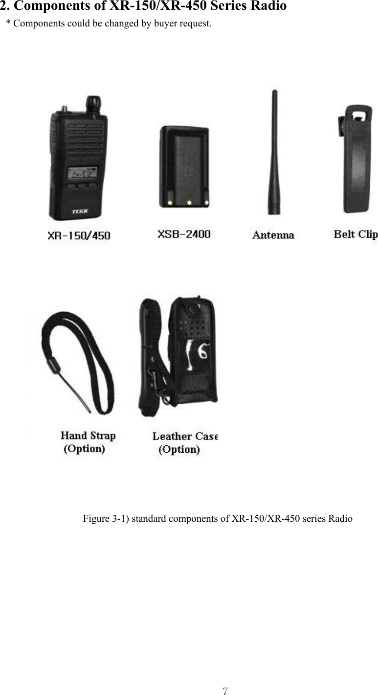
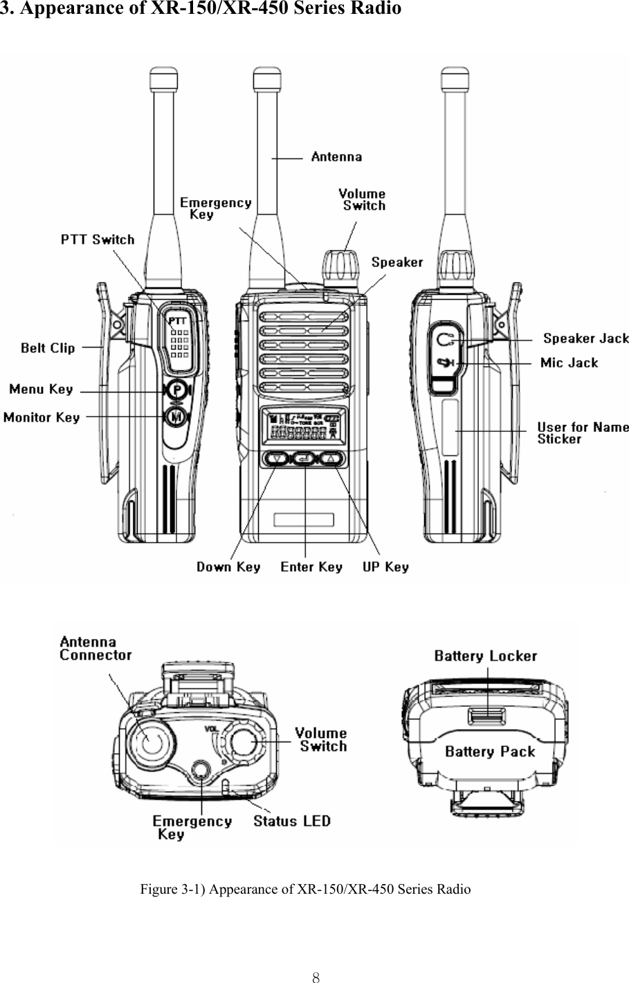
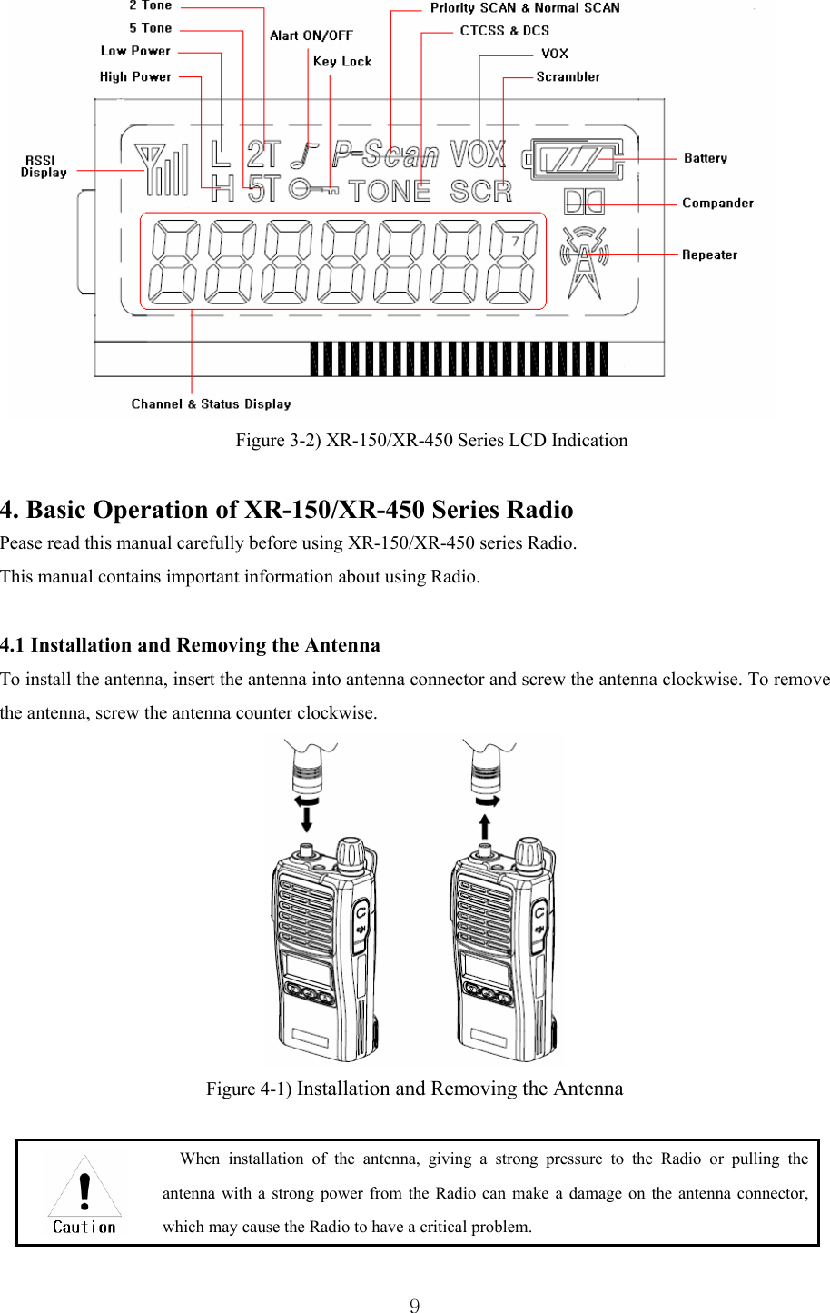
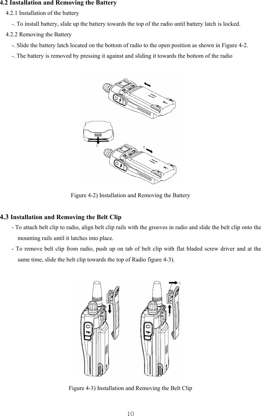
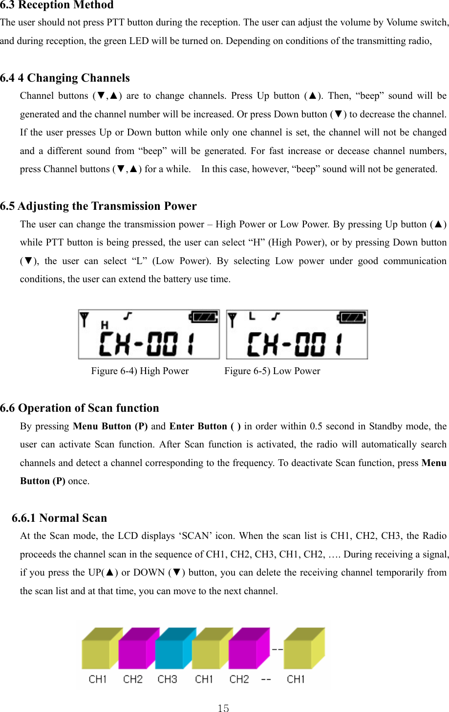
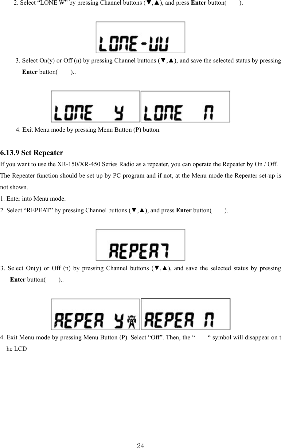
![23Enter button( ). 4. Exit Menu mode by pressing Menu Button(P) button. Select “Off”. Then, the “ “ symbol will disappear on the LCD. 6.13.7 Set VOX Set VOX is to enable users to make transmission for VOX without pressing PTT button. (This function could be available with Ear Mic [External VOX]). By PC Program and menu, it could be set. 1. Enter into Menu mode. 2. Select “H-FrEE” by pressing Channel buttons (▼,▲), and press Enter button( ). 3. Select On(y) or Off (n) by pressing Channel buttons (▼,▲), and press Enter button( ).. 4. Select on(y). Then, the “vox , H-Fr 05“ symbol s will appear on the LCD. Set sensitivity by pressing Channel buttons (▼,▲), and press Enter button( ). 5. Select “Off”. Then, the “ vox “ symbol will disappear on the LCD. 6. Exit Menu mode by pressing Menu Button(P) button. 6.13.8 Set Lone Worker The Set Lone Worker is for transmission of emergency alarm sound without pressing the designated button within a period of time when night patrol or guarding and the Lone Worker can be set to be ON/OFF. The selection can be available by PC program and Menu. 1. Enter into Menu mode.](https://usermanual.wiki/Firmtech/FB755AC.Users-Manual-2/User-Guide-1315328-Page-23.png)