First Computer MH47CW Notebook Computer With 802.11b Wireless LAN User Manual MH47 English manual final
First International Computer Inc Notebook Computer With 802.11b Wireless LAN MH47 English manual final
Contents
- 1. Users manual 1
- 2. Users manual 2
- 3. Users manual 3
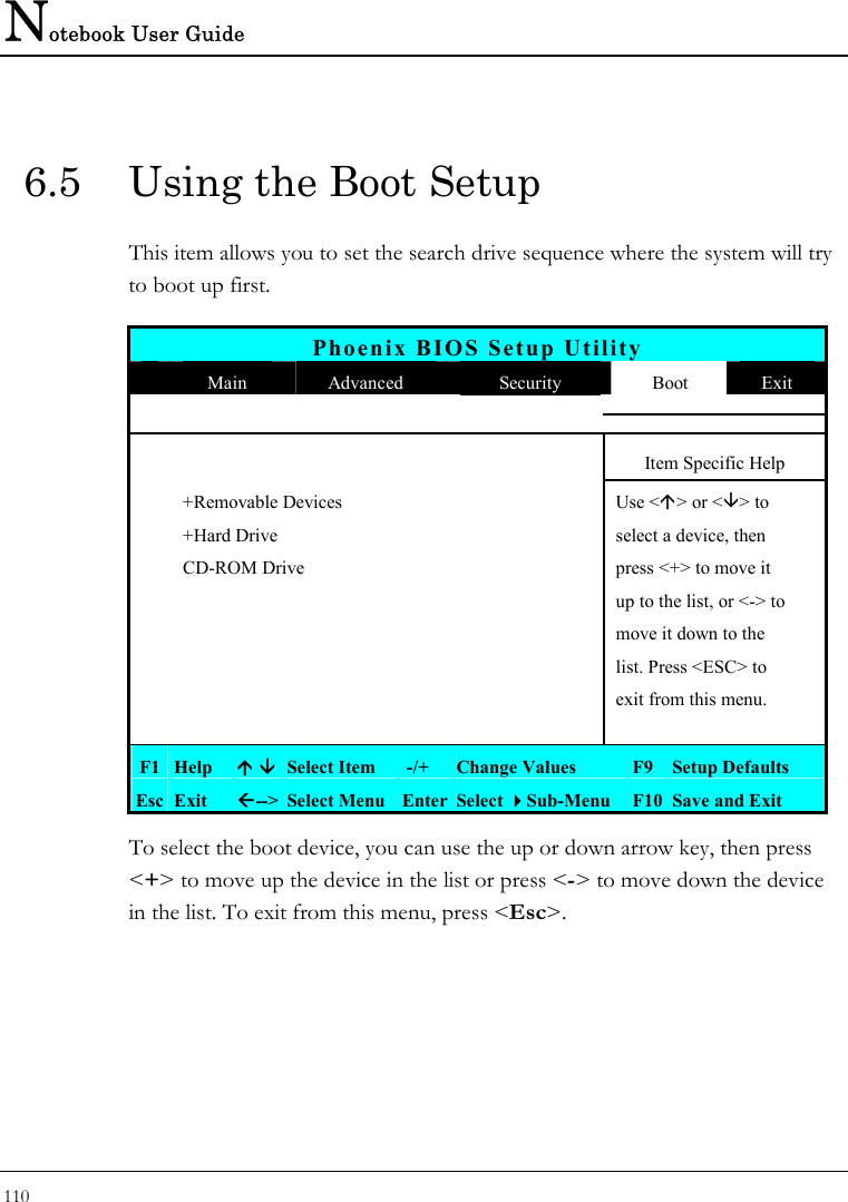
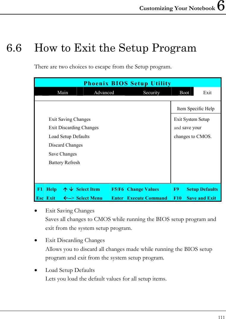
Users manual 3
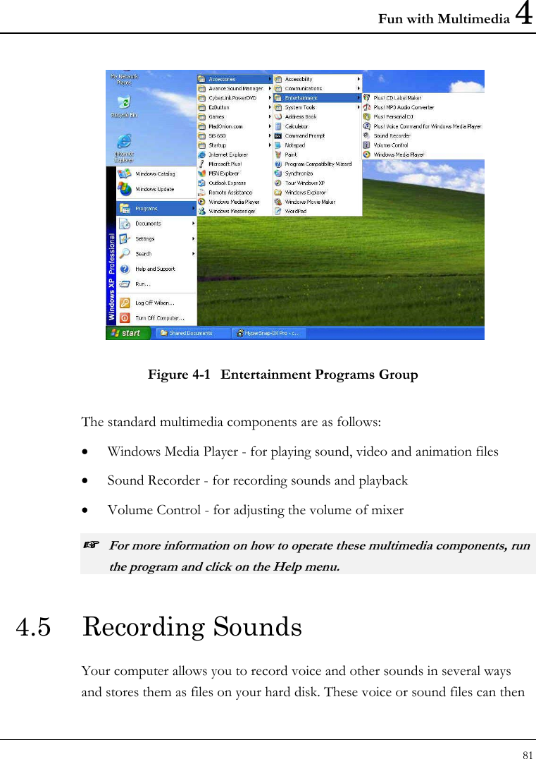
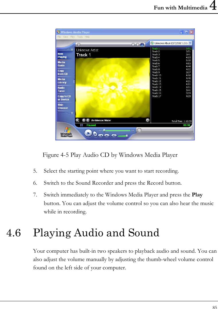
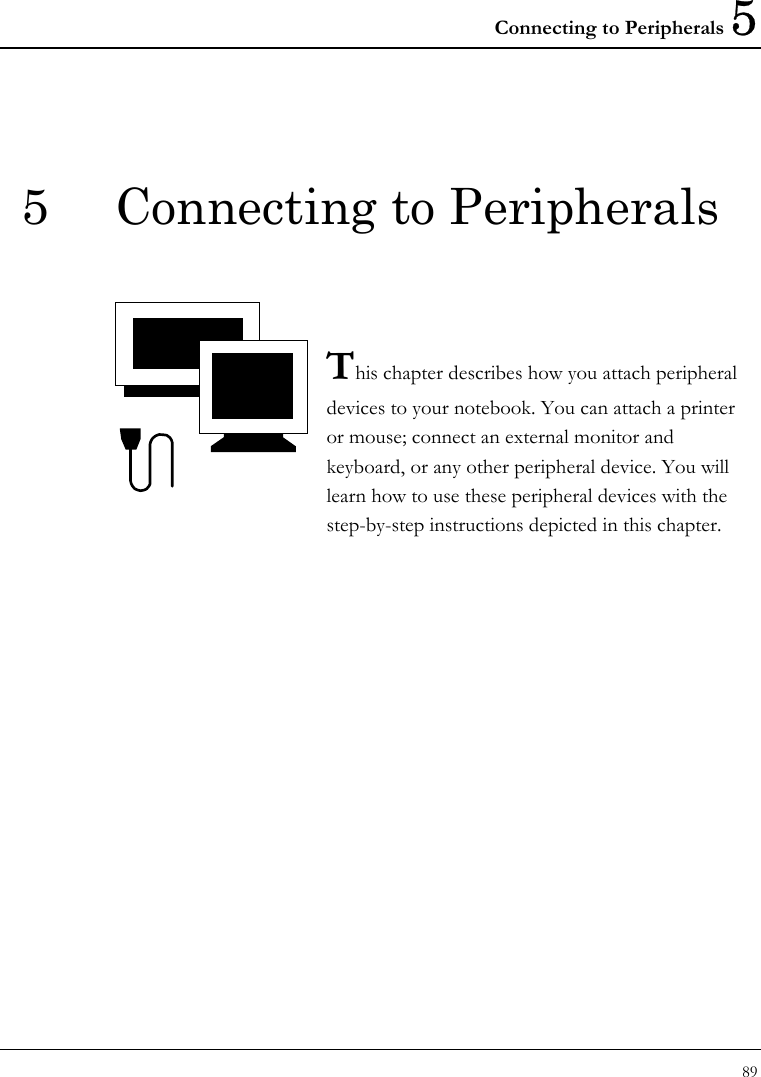
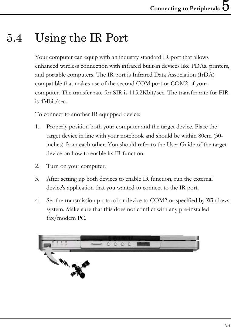
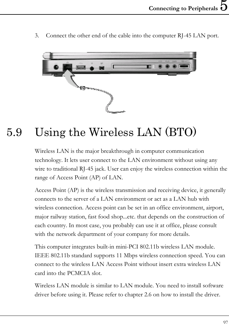
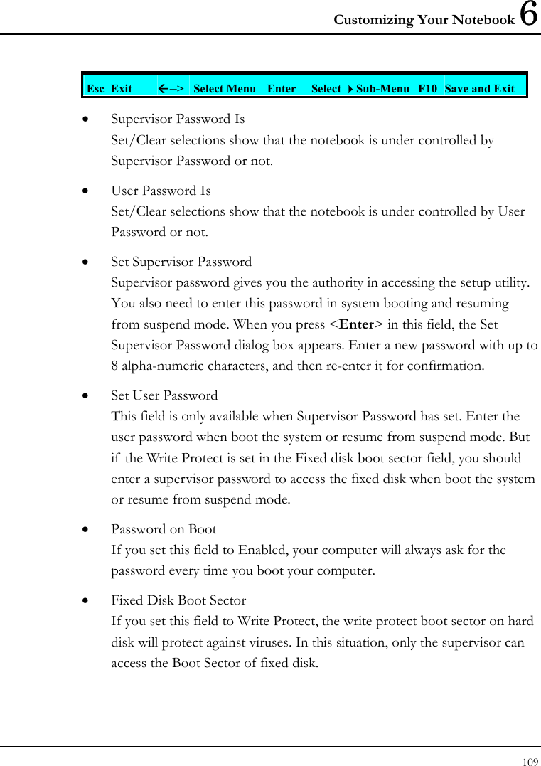
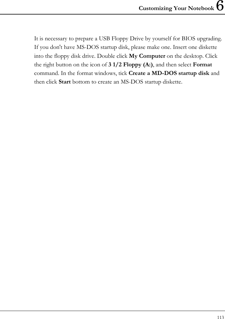
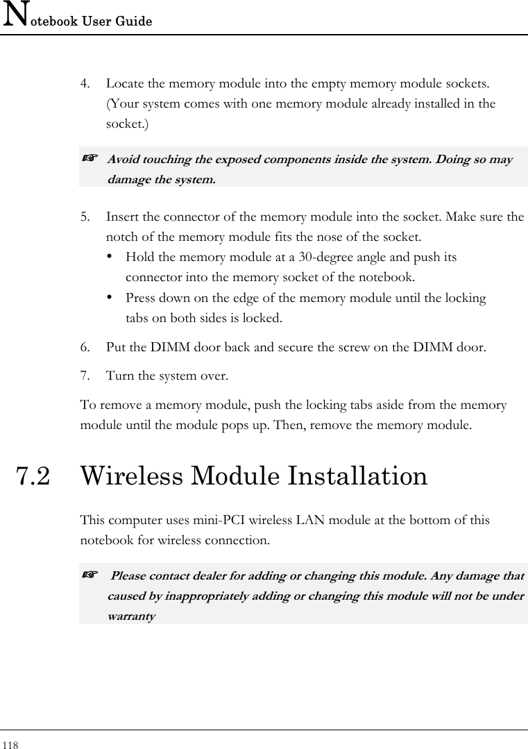
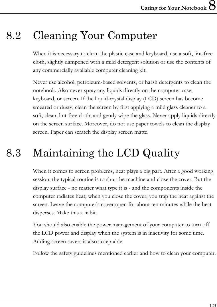
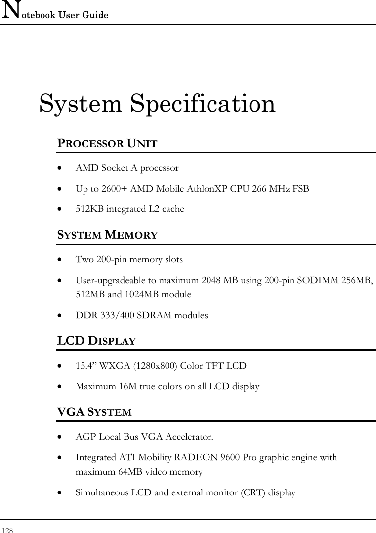
![Notebook User Guide 102 6.2 Using the Main Menu Setup Phoenix BIOS Setup Utility Main Advanced Security Boot Exit Item Specific System Time:[12 :00 :00] <Tab>, <Shift- System Date: [03/03/2003] or <Enter> selects field. 4 Primary Master [IC25N040ATCS04-0 - (PM)] Secondary Master Installed CD/DVD System Memory: 640 KB Extended Memory: 523264 KB CPU Type: Mobile AMD Athlon(tm) XP-M CPU Speed: 1900+ BIOS Version: 0.3A-44A5-0812 F1 Help Ç ÈSelect Item -/+ Change Values F9 Setup Defaults Esc Exit Å--> Select Menu Enter Select Sub-Menu F10 Save and Exit • System Time Allows you to change the system time using the hour:minute:second format of the computer. Enter the current time for reach field and use the <Tab>, <Shift>+<Tab>, or <Enter> key to move from one field or back to another. You can also change the system time from your operating system.](https://usermanual.wiki/First-Computer/MH47CW.Users-manual-3/User-Guide-385594-Page-22.png)
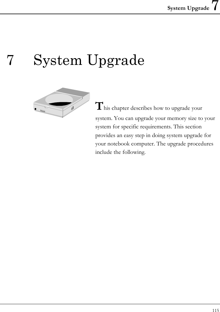
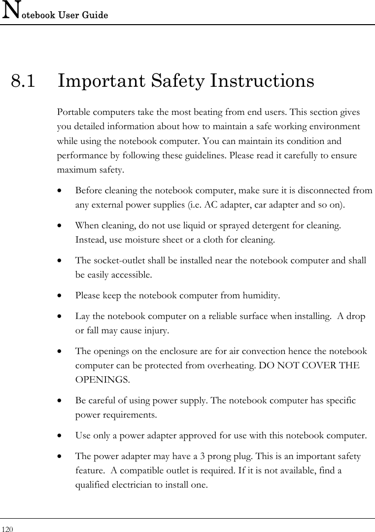
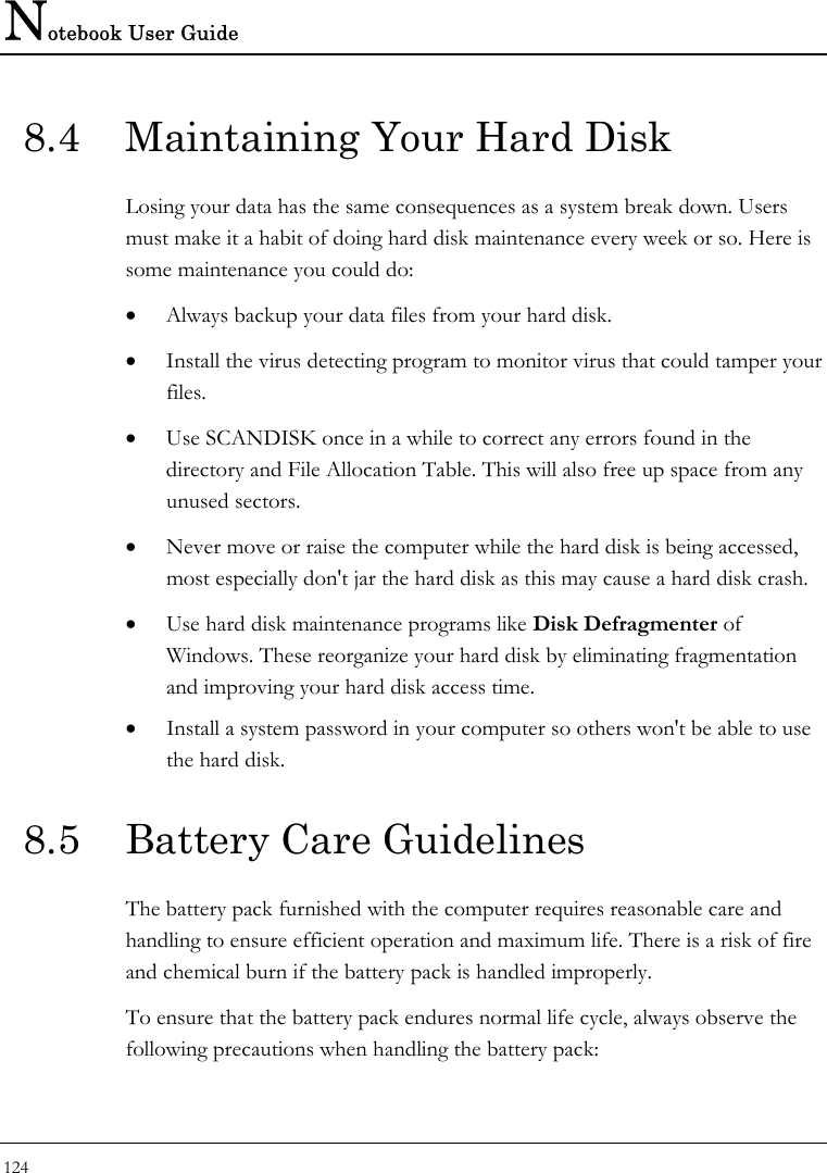
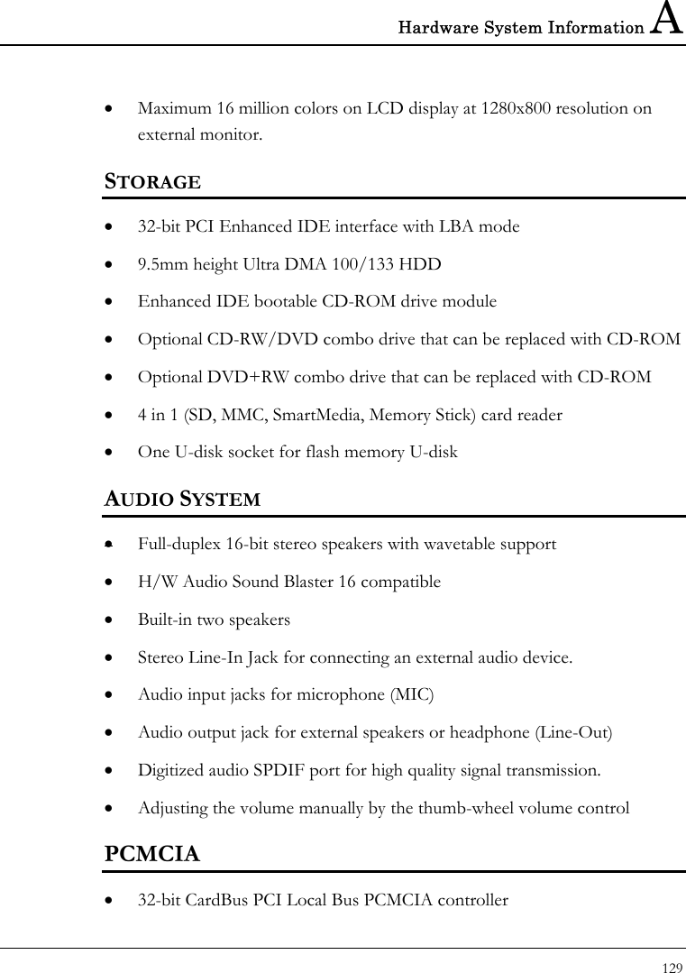
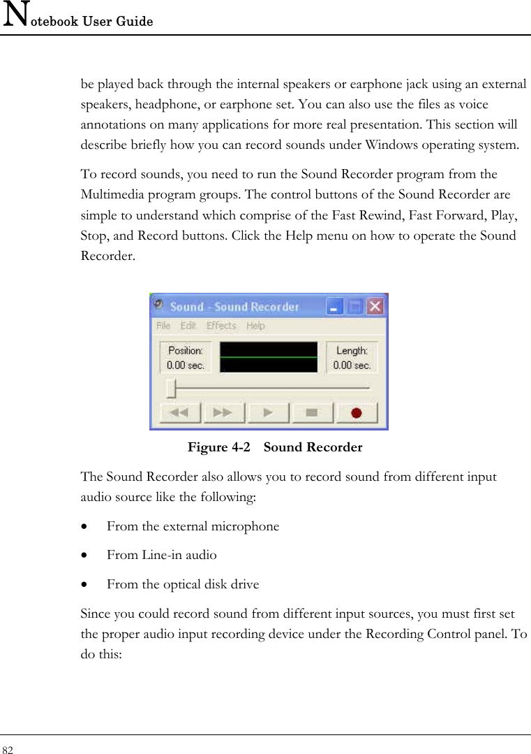
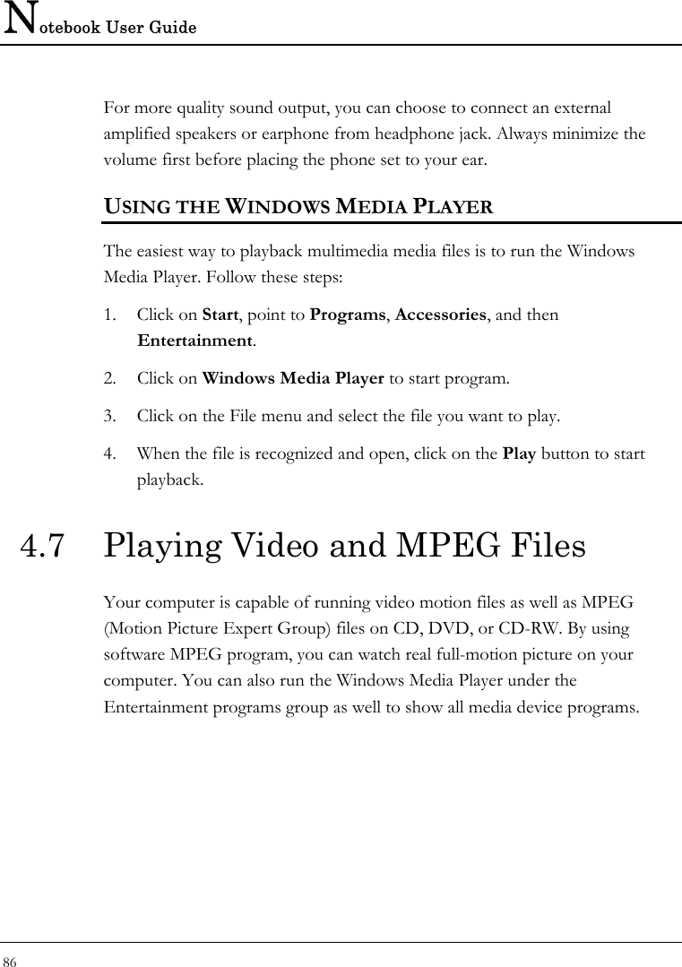
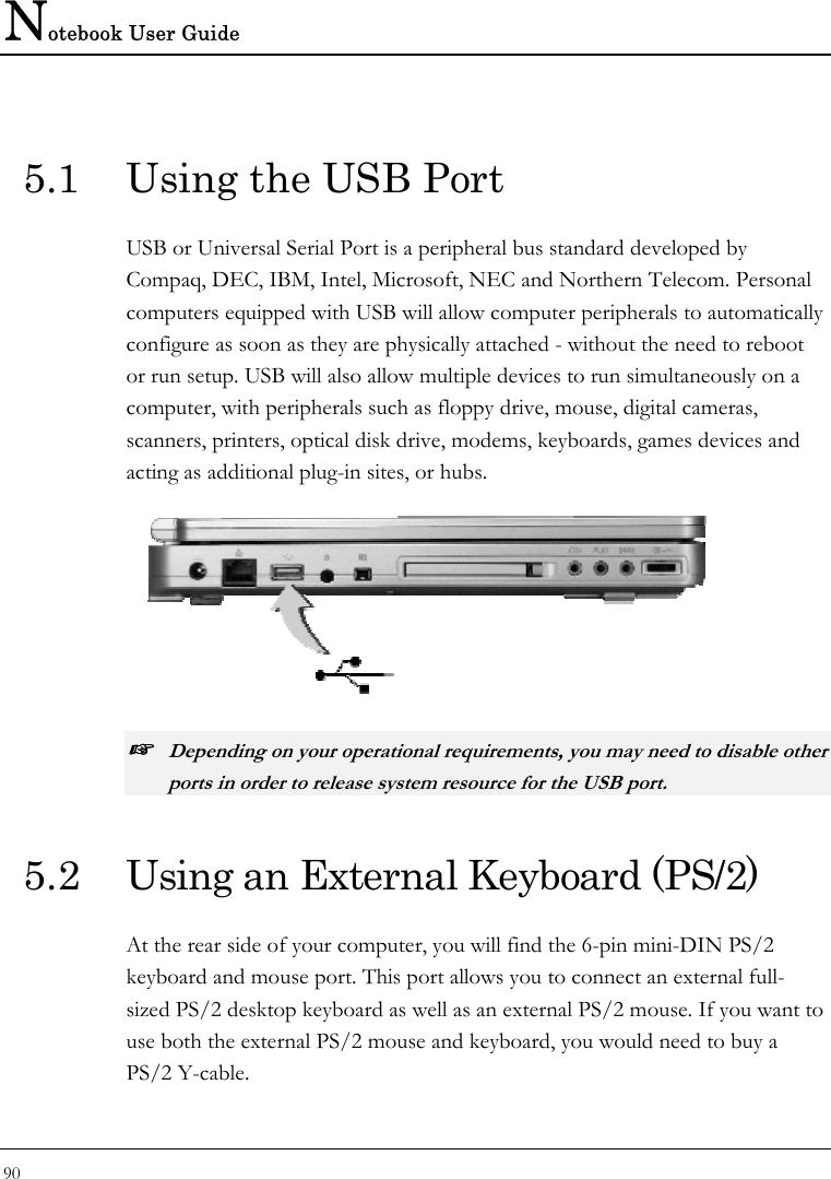
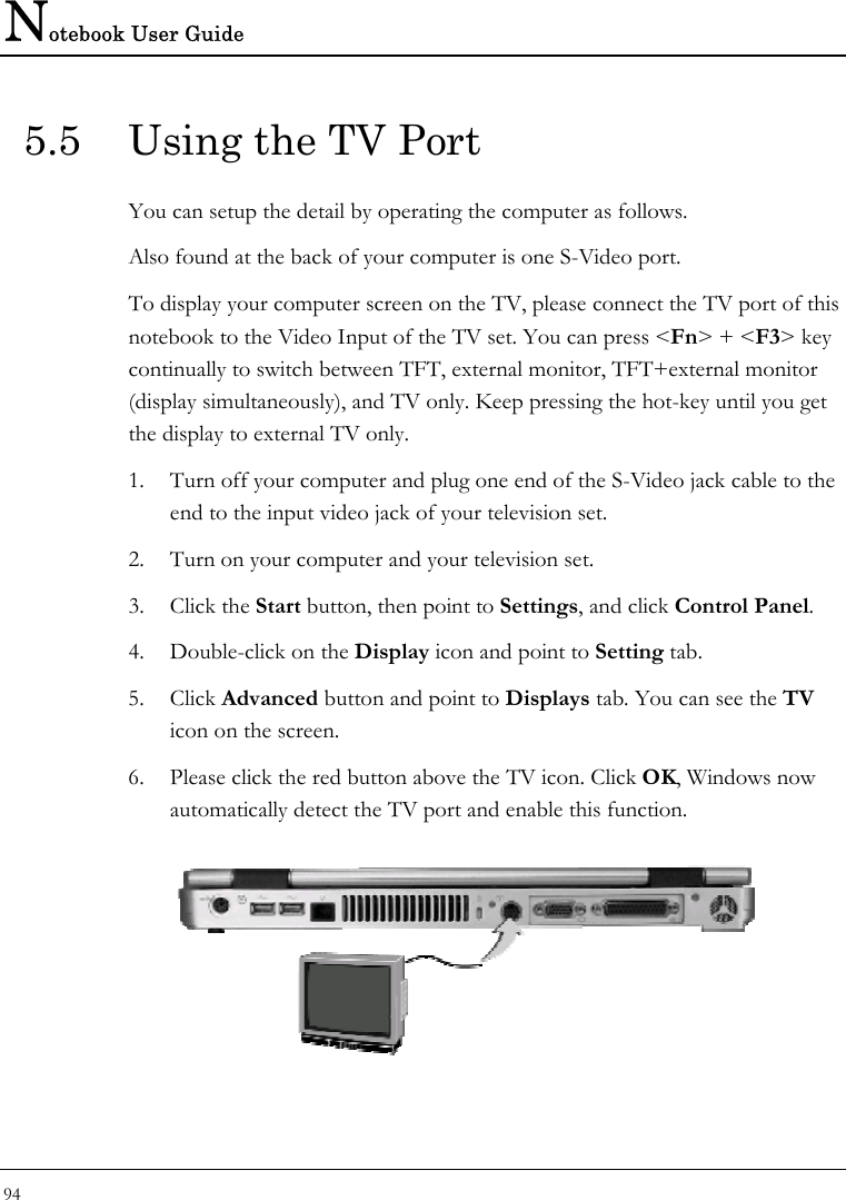
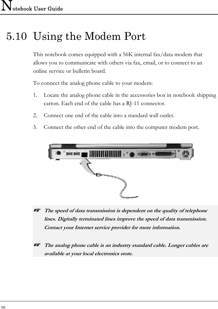
![Customizing Your Notebook 6 103 • System Date Allows you to set the system date using the month/date/year format. Enter the current time for reach field and use the <Tab>, <Shift>+<Tab>, or <Enter> key to move from one field or back to another. You can also change the system time from your operating system. • Primary Master This field display various parameters for the hard disk drive. If type [Auto] is selected, the system automatically sets these parameters. If type [User] is selected, Cylinders, Heads and Sectors can be edited. • Secondary Master This field is for information only as the BIOS automatically detects the optical disk drive. • System Memory This field reports the amount of base (or conventional) memory found by the BIOS during Power-On Self-Test (POST). • Extended Memory This field reports the amount of extended memory found by the BIOS during Power-On Self-Test (POST). • CPU Type This field reports the CPU type information detected by the BIOS during Power-On Self-Test (POST). • CPU Speed This field reports the CPU speed information detected by the BIOS during Power-On Self-Test (POST). • BIOS Version This field is for information only as the BIOS displays the BIOS version during the Power-On Self-Test (POST).](https://usermanual.wiki/First-Computer/MH47CW.Users-manual-3/User-Guide-385594-Page-23.png)
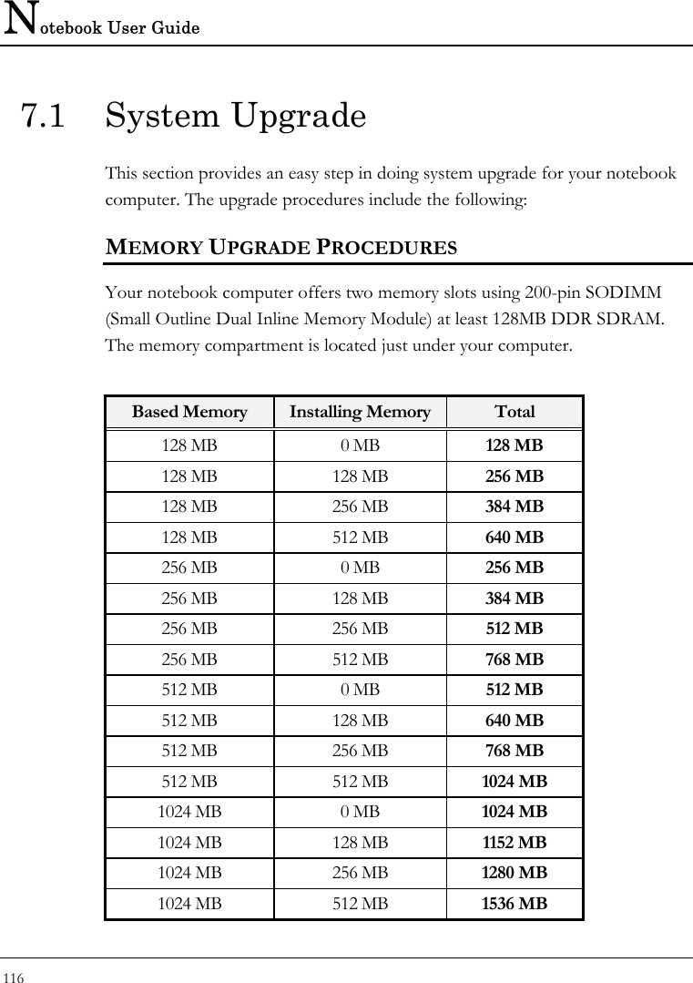
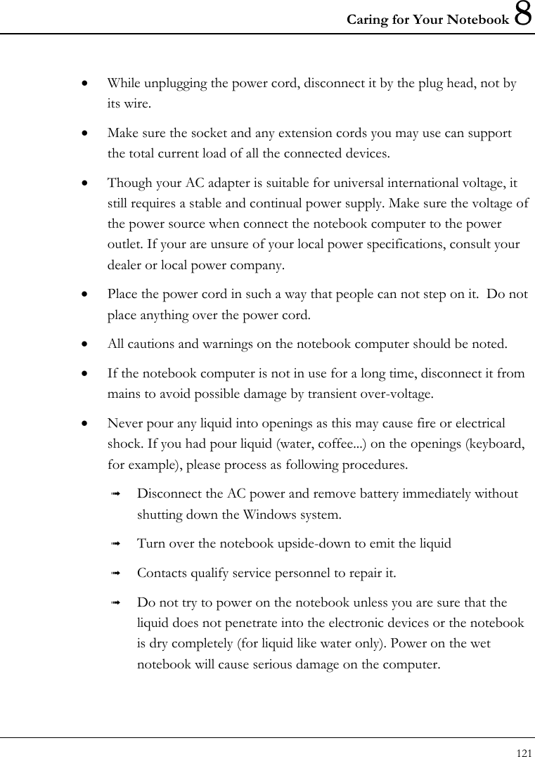
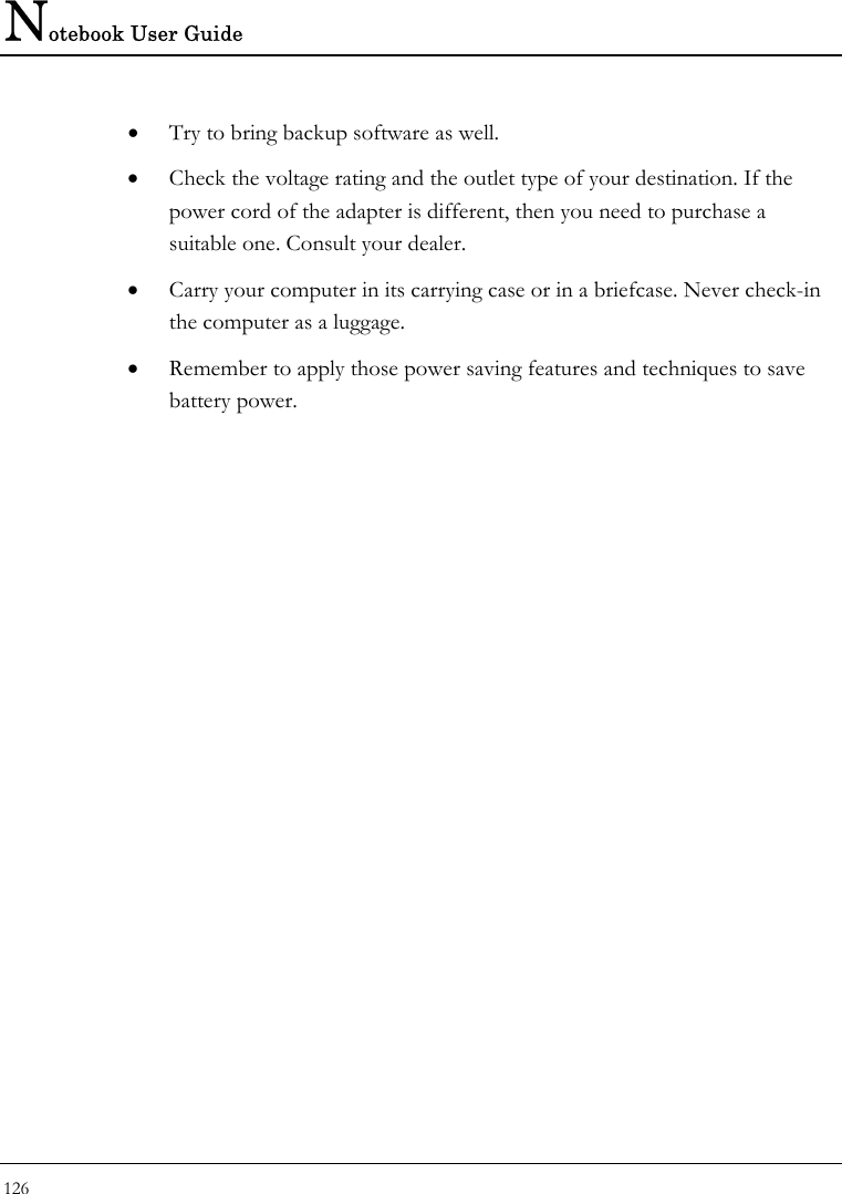
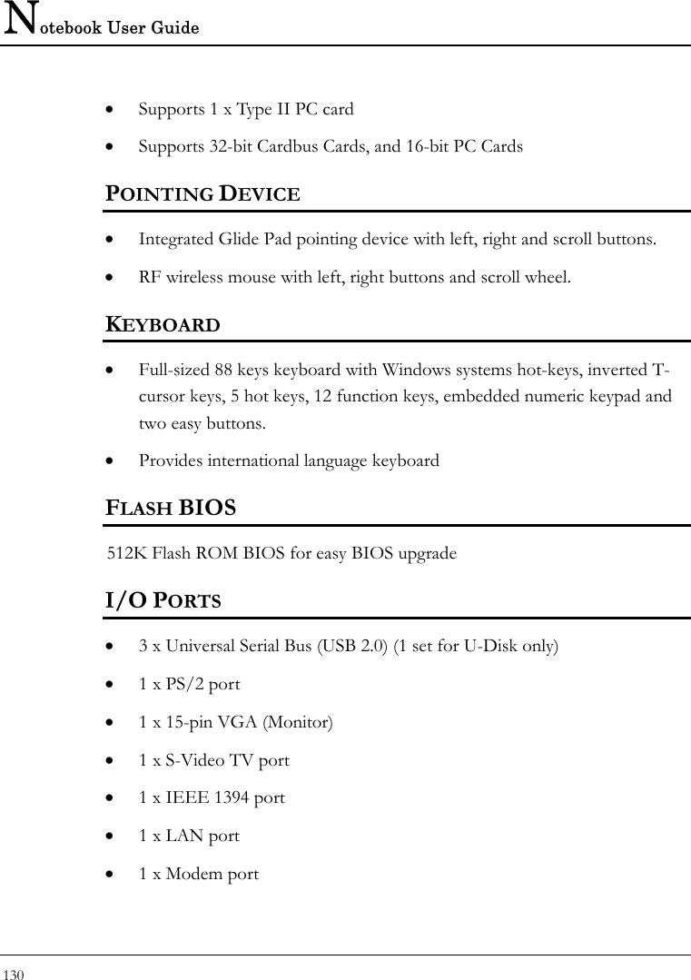
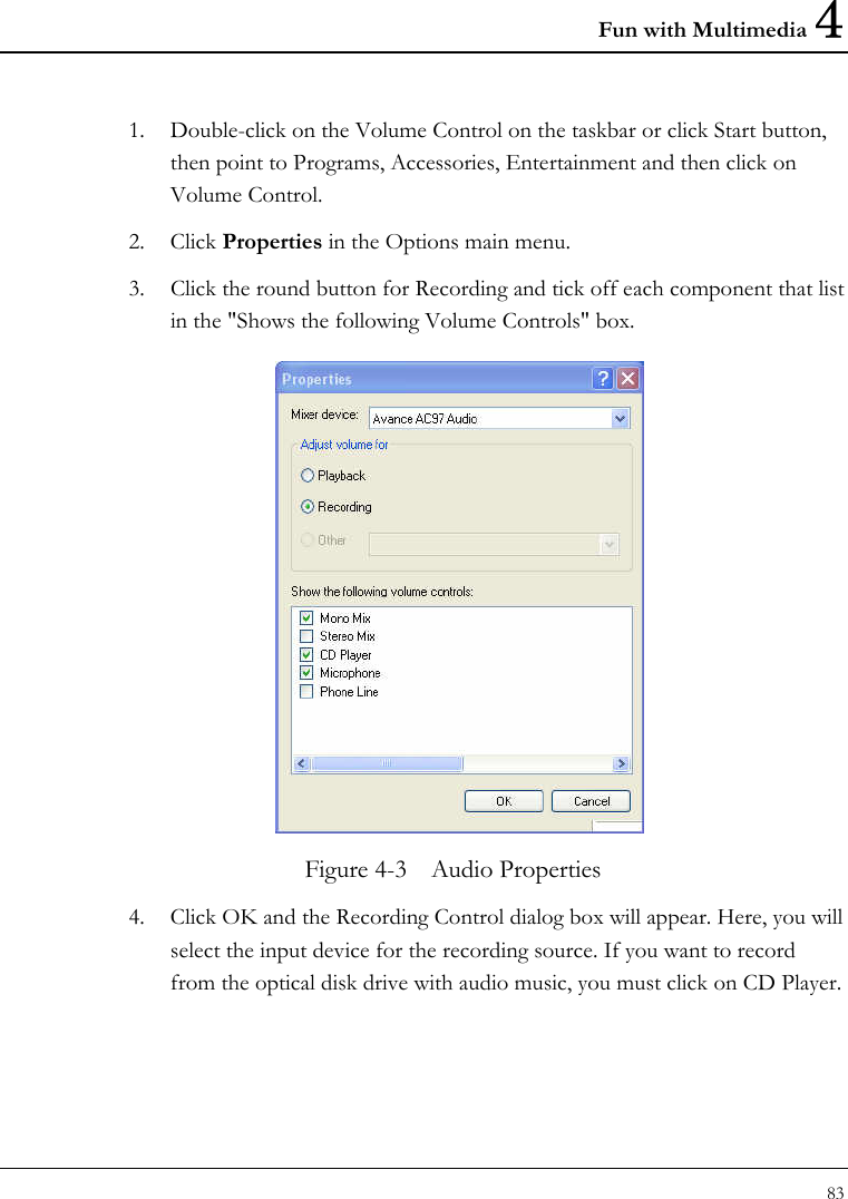
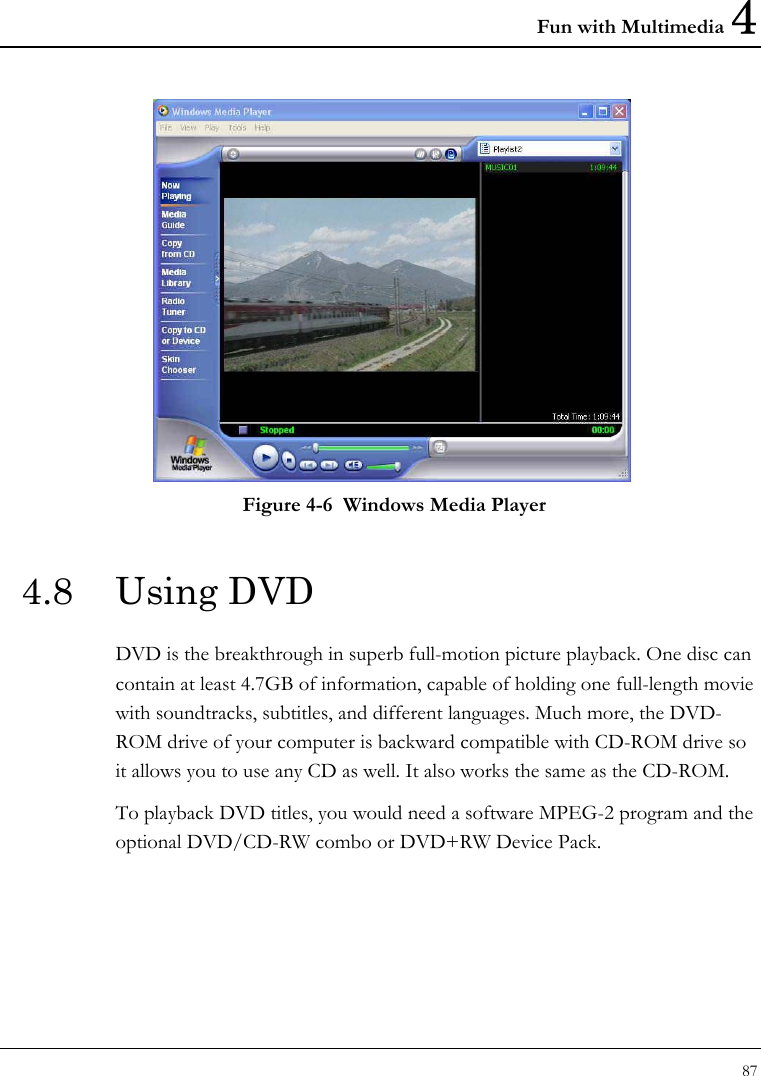
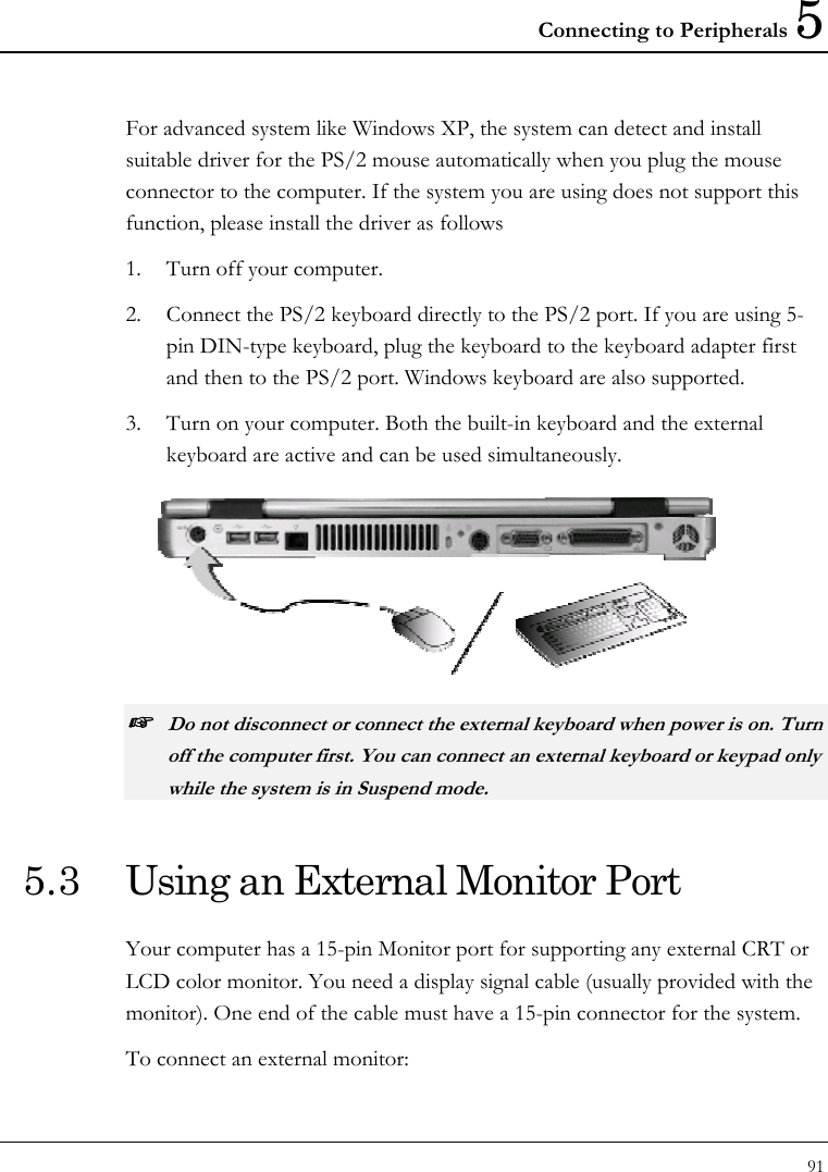
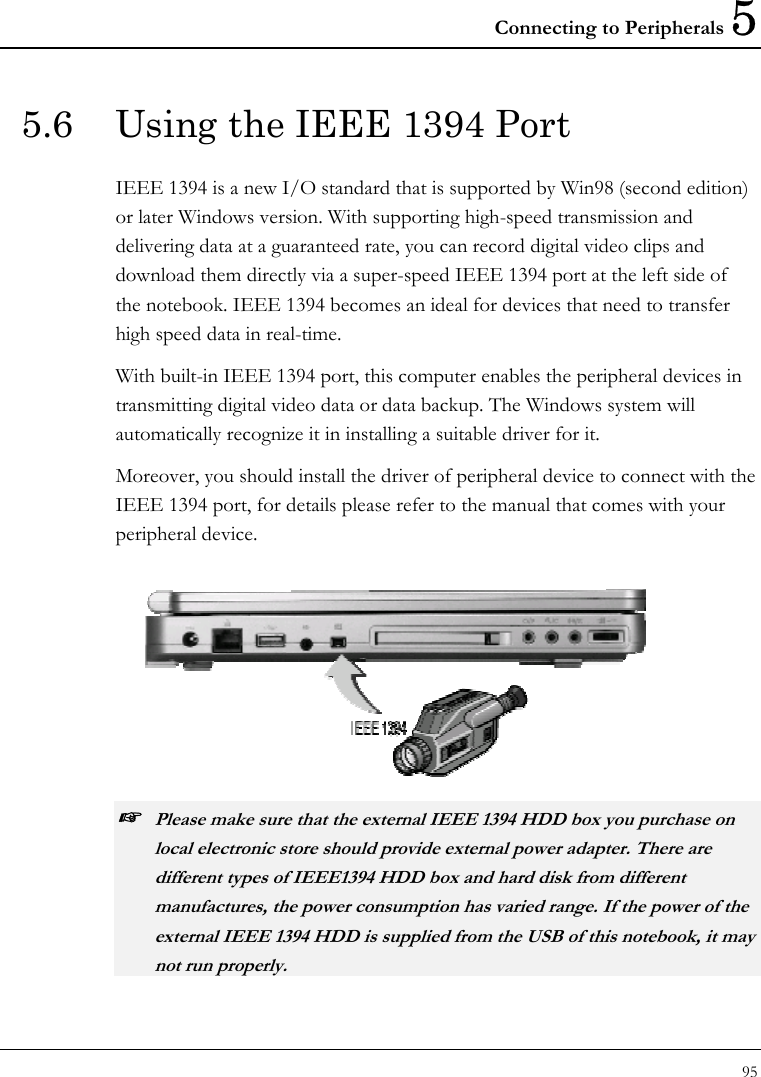
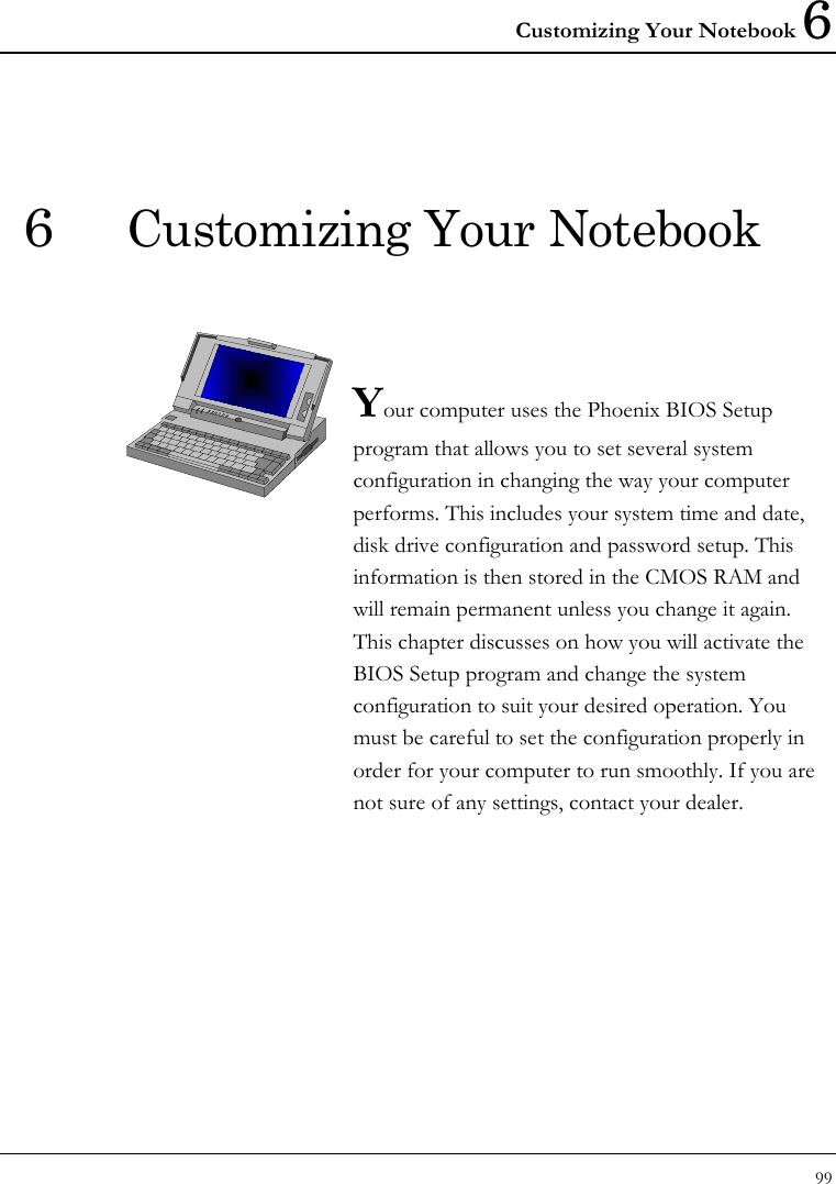
![Notebook User Guide 104 6.2.1 INTERNAL HDD SUB-MENU Phoenix BIOS Setup Utility Main Advanced Security Boot Exit Primary Master [IC25N040ATCS04-0 - (PM)] Item Specific Help Type: [Auto]User = you enter LBA Format parameters of hard-disk Total Sectors: 117210240 drive installed at this Maximum 60012MB connection. Auto = autotypes hard- Multi-Sector Transfers: [16 Sectors] disk drive installed here. LBA Mode Control: [Enabled] CD-ROM = a CD-ROM 32 Bit I/O: [Disabled] drive is installed here. Transfer Mode: [FPIO 4 / DMA 2] ATAPI Removable = Ultra DMA Mode: [Mode 5] Removable disk drive is Installed here. F1 Help Ç ÈSelect Item -/+ Change Values F9 Setup Defaults Esc Exit Å--> Select Menu Enter Select Sub-Menu F10 Save and Exit Use the Type field to select the drive type installed. You can select different drive types as CD-ROM, User, Auto or None by pressing <Space> bar. Set this option to Auto so your computer will automatically detect the drive type during power on. Set this option to None when your computer is not installed any devices. Press <Esc> to return to the Main Menu. 6.3 Using the Advanced CMOS Setup Phoenix BIOS Setup Utility Main Advanced Security Boot Exit](https://usermanual.wiki/First-Computer/MH47CW.Users-manual-3/User-Guide-385594-Page-24.png)
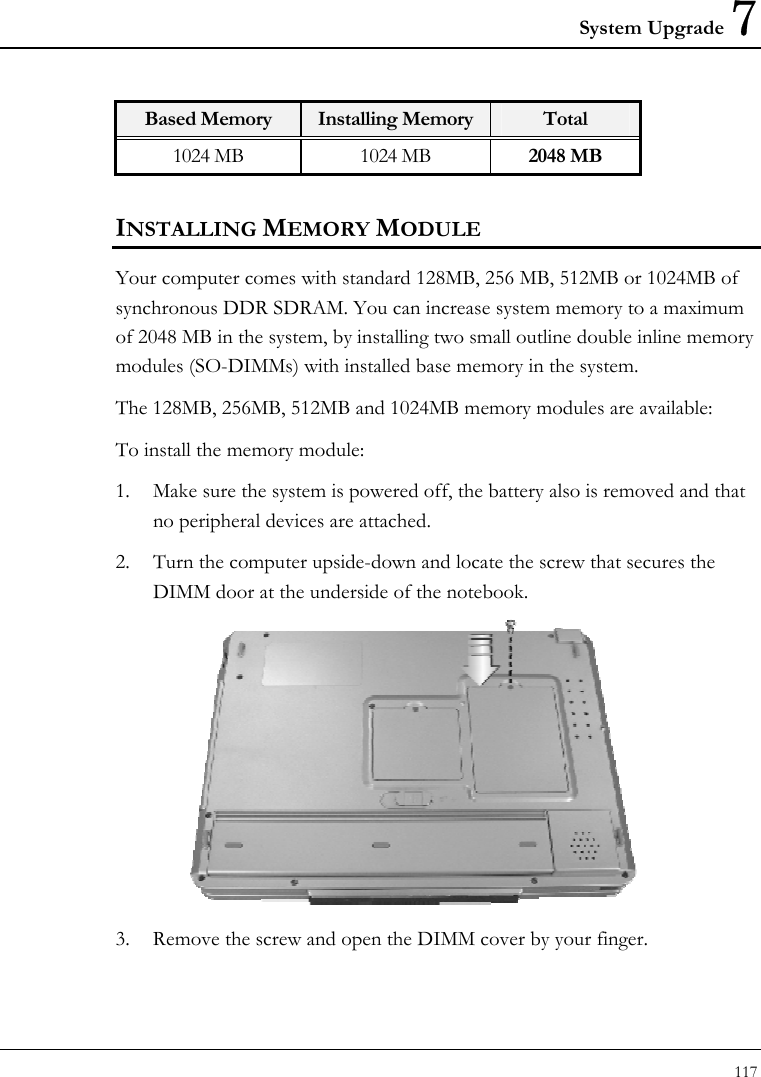
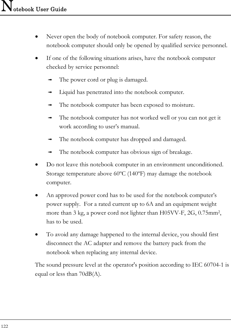
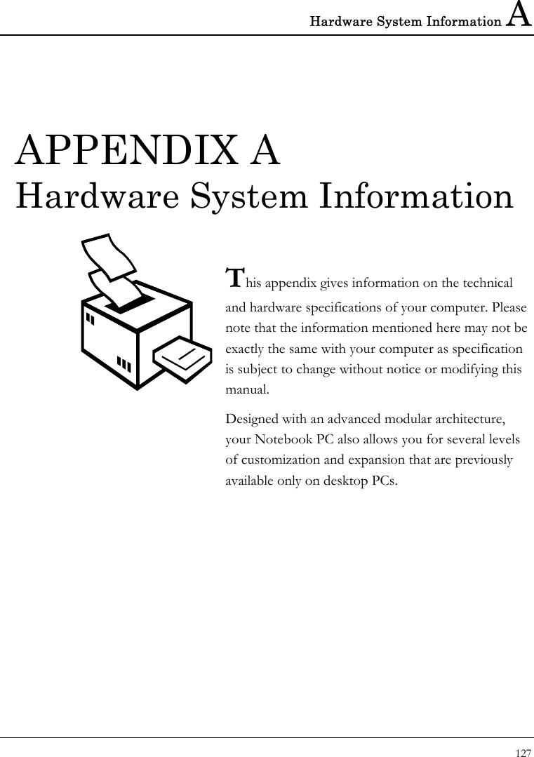
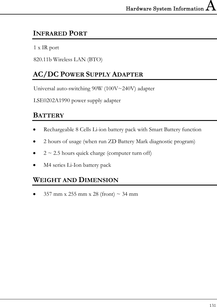
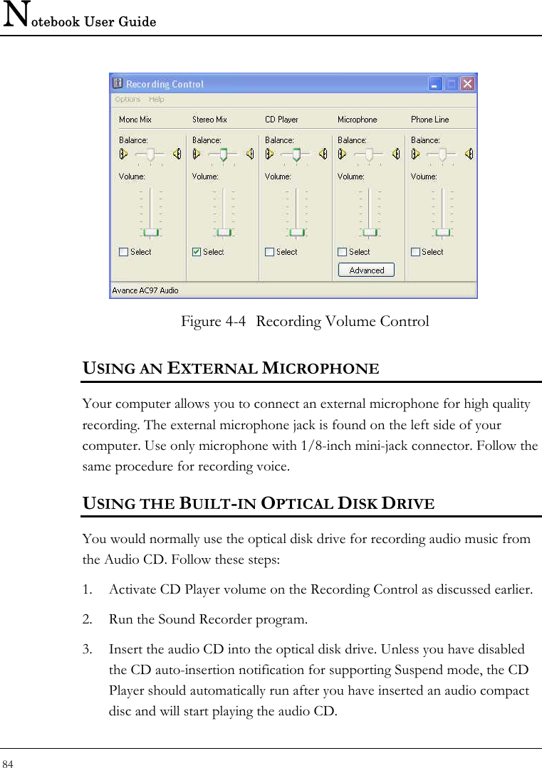
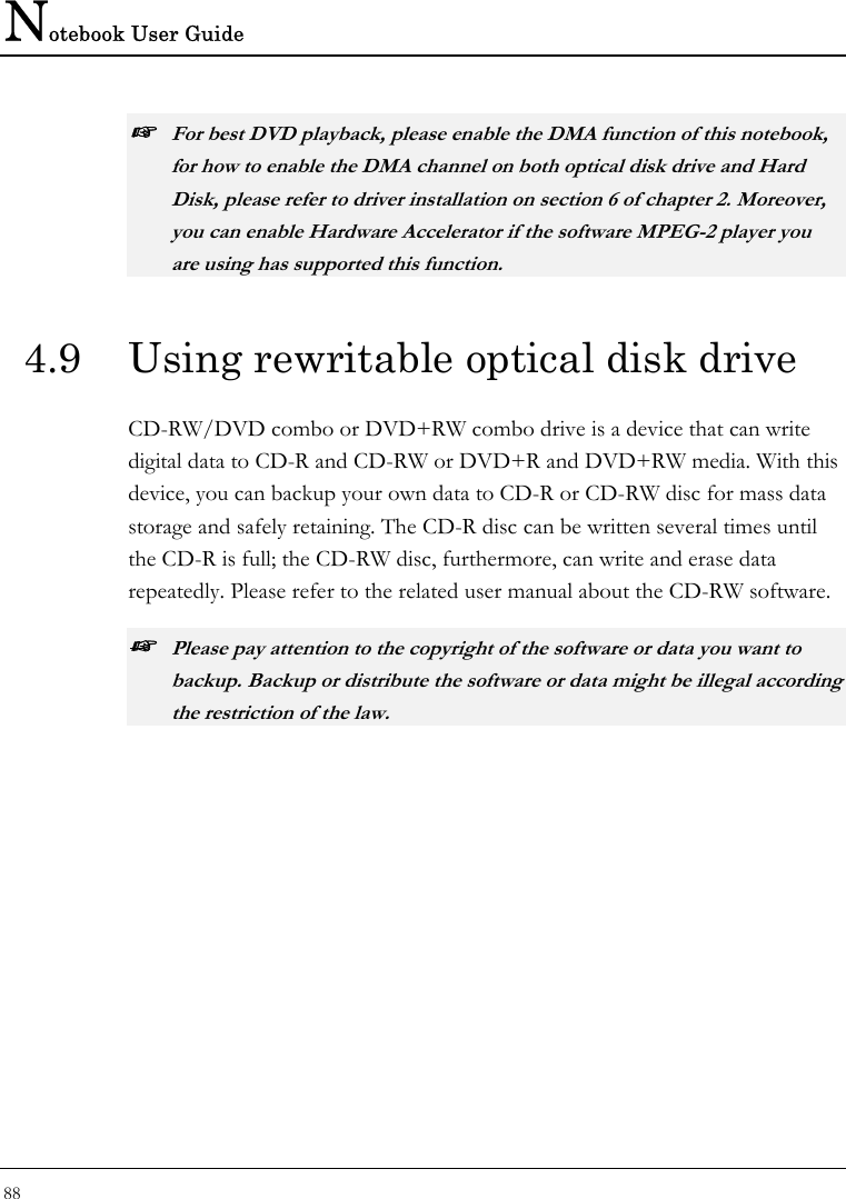
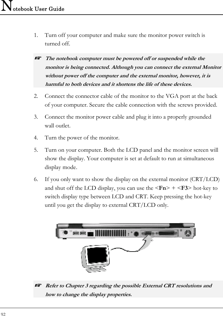
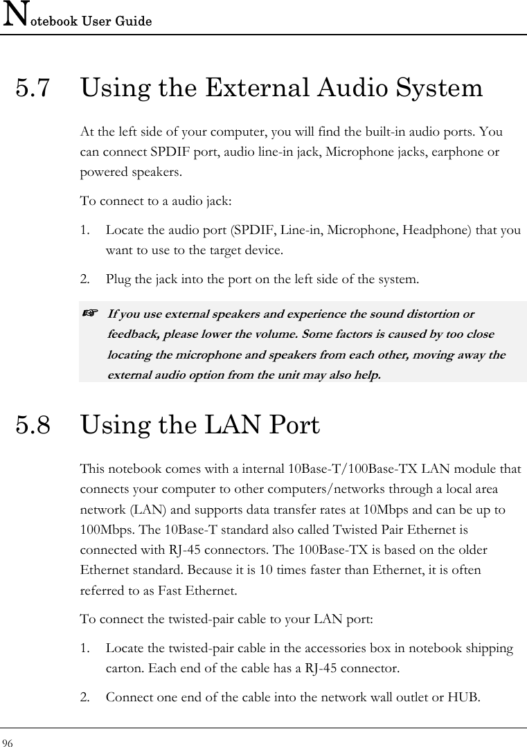
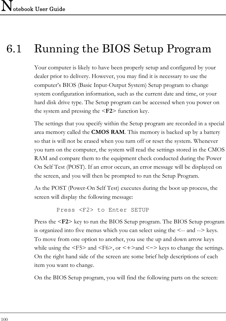
![Customizing Your Notebook 6 105 Item Specific Help Setup Warning Setting items on this menu to incorrect Enable the integrated values may cause your system to malfunction. Local bus IDE adapter Large Disk Access Mode [DOS] Local Bus IDE adapter [Both] 4 Advanced Chipset Control 4 I/O Device Configuration USB BIOS Legacy Support: [Enable] PS/2 mouse [Both] Summary Screen [Disabled] Silent Boot: [Disabled] F1 Help Ç ÈSelect Item -/+ Change Values F9 Setup Defaults Esc Exit Å--> Select Menu Enter Select Sub-Menu F10 Save and Exit • Large Disk Access Mode Allows you to set the Disk Access Mode for different operating system. For Windows system, please select [DOS]. For system other than Windows system, for example, UNIX, Novell NetWare, please select [Other]. If the drive fail when you install a new operating system, please change it to different selection and try again. • Local Bus IDE adapter Lets you specify Enabled or Disabled for activating or inactivating Local Bus IDE when system is booting. Local Bus IDE is the transmission bus for HDD and optical disk drive.](https://usermanual.wiki/First-Computer/MH47CW.Users-manual-3/User-Guide-385594-Page-25.png)
![Notebook User Guide 106 • Advanced Chipset Control Allows you to set or view the parameter of Chipset. • I/O Device Configuration Lets you configure input/output device such as Serial Port, Parallel Port. • USB BIOS Legacy Support Enable or disable support for USB floppy drive. • PS/2 Mouse [Disabled] prevents any installed PS/2 mouse from functioning. [Both] activate both the glide pad and external PS/2 mouse. [Auto] will disable the glide pad function if you had installed the external PS/2 mouse • Summary Screen Displays system configuration on boot. • Silent Boot Lets you specify the boot screen as Logo screen, POST screen by choosing Enabled, Disabled respectively. 6.3.1 I/O ADVANCED CHIPSET CONTROL SUB-MENU Phoenix BIOS Setup Utility Main Advanced Security Boot Exit Advanced Chipset Control Item Specific Help Graphic Aperture [128 MB] Select the size of the CPU Freq. Ratio 133 MHz graphics Aperture for DRAM Freq. Ratio 166 MHz the AGP video device.](https://usermanual.wiki/First-Computer/MH47CW.Users-manual-3/User-Guide-385594-Page-26.png)
![Customizing Your Notebook 6 107 F1 Help Ç ÈSelect Item -/+ Change Values F9 Setup Defaults Esc Exit Å--> Select Menu Enter Select Sub-Menu F10 Save and Exit • Graphic Aperture Select the size of the graphics Aperture for the AGP video device. • CPU Freq. Ratio This field reports the base CPU Frequency Ratio detected by the BIOS during Power-On Self-Test (POST). The real CPU Frequency Ratio is equal to base CPU Frequency Ratio times certain value. So the value here is not the real Frequency of your CPU. • DRAM Freq. Ratio This field reports the base DRAM Frequency Ratio detected by the BIOS during Power-On Self-Test (POST). The real DRAM Frequency Ratio is equal to base DRAM Frequency Ratio times certain value. So the value here is not the real Frequency of your DRAM. 6.3.2 I/O DEVICE CONFIGURATION SUB-MENU Phoenix BIOS Setup Utility Main Advanced Security Boot Exit I/O Device Configuration Item Specific Help Infrared port: [Auto] Configure Infrared port Parallel port: [Enabled] using options: Mode: [EPP] [Disabled] No configuration, [Enabled] User configuration, [Auto]](https://usermanual.wiki/First-Computer/MH47CW.Users-manual-3/User-Guide-385594-Page-27.png)
![Notebook User Guide 108 BIOS or OS chooses configuration, F1 Help Ç ÈSelect Item -/+ Change Values F9 Setup Defaults Esc Exit Å--> Select Menu Enter Select Sub-Menu F10 Save and Exit • Infrared port You can select the Enabled, Disabled, or Auto option for enabled or disabled the port, or automatically sensed by BIOS or OS. If you select Enable, you also need to set the IR mode, Base I/O for the IR device. • Parallel port: You can select the Enabled, Disabled, or Auto option for enabled or disabled the port, or automatically sensed by BIOS or OS. If you select Enable, you also need to set the Parallel port mode (EPP, ECP, Bi-directional). 6.4 Security Menu Setup Phoenix BIOS Setup Utility Main Advanced Security Boot Exit Item Specific Help Supervisor Password Is Clear Supervisor Password User Password Is Clear controls access to the Set Supervisor Password [Enter] setup utility. Set User Password [Enter] Password on boot [Disabled] Fixed disk boot sector [Normal] F1 Help Ç ÈSelect Item -/+ Change Values F9 Setup Defaults](https://usermanual.wiki/First-Computer/MH47CW.Users-manual-3/User-Guide-385594-Page-28.png)