First Computer MR031BT Notebook PC User Manual
First International Computer Inc Notebook PC
manual
1
FIC
MR031
User Guide

Notebook User Guide
2
Copyright©2007
All Rights Reserved - Printed in Taiwan
Notebook Computer User Guide
Original Issue: 2007/10
This manual guides you in setting up and using your new notebook computer.
Information in this manual has been carefully checked for accuracy and is
subject to change without notice.
No part of this manual may be reproduced, stored in a retrieval system, or
transmitted, in any form or by any means, electronic, mechanical, photocopy,
recording, or otherwise, without prior written permission.
Trademarks
Product names used herein are for identification purposes only and may be the
trademarks of their respective companies.
Microsoft, Windows XP, Windows MCE, Windows Vista, and Windows
Sound System are trademarks of Microsoft Corporation.
Intel ®, Intel® CoreTM2 Duo, Intel ® HD Audio (Azalia) are registered
trademark of Intel Corporation.
Sound Blaster, Sound Blaster Pro are trademarks of Creative Technology.
All other brands or product names mentioned in this manual are trademarks or
registered trademarks of their respective companies.

Notebook User Guide
3
FCC Information to User
Safety and Care Instructions
No matter what your level of experience with computers, please make sure you
read the safety and care instructions. This information can help protect you
and your computer from possible harm.
For Safety Regulation:
z Risk of explosion if battery is replaced by an incorrect type.
z For electrical safety concerns, only use telephone cables rated
26AWG or higher.
z The Optical drive is a Class 1 Laser Product.
z Li-Ion battery is vulnerable, do not charge it with other power
adapter, or it may cause fire or explosion.
z For the power supply of this equipment,
An approved power cord has to be used.
Make sure the socket and any extension cord(s) you use can
support the total current load of all the connected devices.
Before cleaning the computer, make sure it is disconnected
from any external power supplies (i.e. AC adapter).
Radio and television interference
Warning: Use the specified shielded power cord and shielded signal cables
with this computer, so as not to interfere with radio and television reception. If
you use other cables, it may cause interference with radio and television
reception.
This equipment has been tested and found to comply with the limits for a
Class B digital device, pursuant to Part 15 of the FCC Rules. These limits are
designed to provide reasonable protection against harmful interference in a
residential installation. This equipment generates, uses and can radiate radio

Notebook User Guide
4
frequency energy and, if not installed and used in accordance with the
instructions, may cause harmful interference to radio communications.
However, there is no guarantee that interference will not occur in a particular
installation. If this equipment does not cause harmful interference to radio or
television reception, which can be determined by turning the equipment off
and on, the user is encourage to try to correct the interference by one or more
of the following measures:
• Reorient or relocate the receiving antenna
• Increase the separation between the device and receiver
• Connect the device into an outlet on a circuit different from that to
which the receiver is connected.
• Consult the dealer or an experienced radio/television technician for help.
You may find helpful the following booklet, prepared by the Federal
Communications Commission: Interference Handbook (stock number 004-
000-00345-4). This booklet is available from the U.S. Government Printing
Office, Washington, DC20402
Warning: The user must not modify or change this computer without
approval. Modification could void authority to this equipment.
Canadian Department of Communications Compliance
Statement
This Class B digital apparatus meets all requirement of the Canadian
Interference-Causing Equipment Regulations.
Shielded Cables Notice
All connections to other computing devices must be made using shielded
cables to maintain compliance with FCC regulations.

Notebook User Guide
5
Peripheral Devices Notice
Only peripherals (input/output devices, terminals, printers, etc) certified to
comply with Class B limits may be attached to this equipment. Operation with
non-certified peripherals is likely to result in interference to radio and TV
reception.
Optical Disk Drive Notice
The optical disk drive is Class 1 Laser Product.
Caution
Changes or modifications not expressly approved by the manufacturer may
void the user’s authority, which is granted by the Federal Communications
Commission, to operate this computer.
Use Conditions
This part complies with Part 15 of the FCC Rules. Operation is subject to the
following conditions: (1) this device may not cause harmful interference, and
(2) this device must accept any interference received, including interference
that may cause undesired operation.
Warranty requirement in the manual: Along with the user
documentation the importer/distributor must provide a statement that
warranty services are included in the responsibilities of the distributor
representative.
Canada (see also United States)
Canada Radio Frequency Interference Requirements
This Class B digital apparatus complies with Canadian ICES-003, Issue 2, and
RSS-210, Issue 4 (Dec. 2000).

Notebook User Guide
6
“To prevent radio interference to the licensed service, this device is intended
to be operated indoors and away from windows to provide maximum
shielding. Equipment (or its transmit antenna) that is installed outdoors is
subject to licensing.”
Cet appareil numérique de la classe B est conforme à la norme NMB-003, No.
2, et CNR-210, No. 4 (Dec. 2000).
« Pour empêcher que cet appareil cause du brouillage au service faisant l'objet
d'une licence, il doit être utilisé à l'intérieur et devrait être placé loin des
fenêtres afin de fournir un écran de blindage maximal. Si le matériel (ou son
antenne d'émission) est installé à l'extérieur, il doit faire l'objet d'une licence. »
Regulatory Information
Intel(R) Wireless WiFi Link 4965AGN
Intel(R) Wireless WiFi Link 4965AG_
Intel(R) Wireless WiFi Link 4965AGN and Intel(R)
Wireless WiFi Link 4965AG_
The information in this document applies to the following products:
Quad-mode wireless LAN adapters (802.11a/802.11b/802.11g/802.11n)
Intel(R) Wireless WiFi Link 4965AGN (model WM4965AGN)
Tri-mode wireless LAN adapters (802.11a/802.11b/802.11g)
Intel(R) Wireless WiFi Link 4965AG_ (model WM4965AG_)
7 NOTE: Due to the evolving state of regulations and standards in the
wireless LAN field (IEEE 802.11 and similar standards), the information
provided herein is subject to change. Intel Corporation assumes no
responsibility for errors or omissions in this document. Nor does Intel
make any commitment to update the information contained herein.
Information for the user

Notebook User Guide
7
Safety Notices
The FCC with its action in ET Docket 96-8 has adopted a safety standard for
human exposure to radio frequency (RF) electromagnetic energy emitted by
FCC certified equipment. The Intel(R) Wireless WiFi Link 4965AGN or
Intel(R) Wireless WiFi Link 4965AG_adapter meet the Human Exposure
limits found in OET Bulletin 65, supplement C, 2001, and ANSI/IEEE C95.1,
1992. Proper operation of this radio according to the instructions found in this
manual will result in exposure substantially below the FCC’s recommended
limits.
The following safety precautions should be observed:
z Do not touch or move antenna while the unit is transmitting or receiving.
z Do not hold any component containing the radio such that the antenna is
very close or touching any exposed parts of the body, especially the face or
eyes, while transmitting.
z Do not operate the radio or attempt to transmit data unless the antenna is
connected; if not, the radio may be damaged.
z Use in specific environments:
Ö The use of wireless devices in hazardous locations is limited by the
constraints posed by the safety directors of such environments.
Ö The use of wireless devices on airplanes is governed by the Federal
Aviation Administration (FAA).
Ö The use of wireless devices in hospitals is restricted to the limits set
forth by each hospital.
z Antenna use:
Ö In order to comply with FCC RF exposure limits, low gain integrated
antennas should be located at a minimum distance of 20 cm (8 inches)
or more from the body of all persons.
Ö High-gain, wall-mount, or mast-mount antennas are designed to be
professionally installed and should be located at a minimum distance
of 30 cm (12 inches) or more from the body of all persons. Please
contact your professional installer, VAR, or antenna manufacturer for
proper installation requirements.
z Explosive Device Proximity Warning (see below)
Notebook User Guide
8
z Antenna Warning (see below)
z Use on Aircraft Caution (see below)
z Other Wireless Devices (see below)
z Power Supply (Access Point) (see below)
Explosive Device Proximity Warning
Warning: Do not operate a portable transmitter (such as a wireless
network device) near unshielded blasting caps or in an explosive environment
unless the device has been modified to be qualified for such use.
Antenna Warnings
Warning: To comply with the FCC and ANSI C95.1 RF exposure limits, it
is recommended for the Intel(R) Wireless WiFi Link 4965AGN or Intel(R)
Wireless WiFi Link 4965AG_ adapter installed in a desktop or portable
computer, that the antenna for this device be installed so as to provide a
separation distance of at least 20 cm (8 inches) from all persons and that the
antenna must not be co-located or operating in conjunction with any other
antenna or radio transmitter. It is recommended that the user limit exposure
time if the antenna is positioned closer than 20 cm (8 inches).
Warning: Intel(R) PRO/Wireless LAN products are not designed for use
with high-gain directional antennas. Use of such antennas with these products
is illegal.
Use On Aircraft Caution
Caution: Regulations of the FCC and FAA prohibit airborne operation of
radio-frequency wireless devices because their signals could interfere with
critical aircraft instruments.

Notebook User Guide
9
Other Wireless Devices
Safety Notices for Other Devices in the Wireless Network: See the
documentation supplied with wireless Ethernet adapters or other devices in
the wireless network.
Local Restrictions on 802.11a, 802.11b, 802.11g and 802.11n Radio Usag
Caution: Due to the fact that the frequencies used by 802.11a, 802.11b,
802.11g and 802.11n wireless LAN devices may not yet be harmonized in all
countries, 802.11a, 802.11b, 802.11g and 802.11n products are designed for
use only in specific countries, and are not allowed to be operated in countries
other than those of designated use. As a user of these products, you are
responsible for ensuring that the products are used only in the countries for
which they were intended and for verifying that they are configured with the
correct selection of frequency and channel for the country of use. The device
transmit power control (TPC) interface is part of the Intel(R)
PROSet/Wireless software. Operational restrictions for Equivalent Isotropic
Radiated Power (EIRP) are provided by the system manufacturer. Any
deviation from the permissible power and frequency settings for the country
of use is an infringement of national law and may be punished as such.
For country-specific information, see the additional compliance information
supplied with the product.
Wireless interoperability
The Intel(R) Wireless WiFi Link 4965AGN or Intel(R) Wireless WiFi Link
4965AG_ is designed to be interoperable with other wireless LAN products
that are based on direct sequence spread spectrum (DSSS) radio technology
and to comply with the following standards:
z IEEE Std. 802.11b compliant Standard on Wireless LAN
z IEEE Std. 802.11g compliant Standard on Wireless LAN
z IEEE Std. 802.11a compliant Standard on Wireless LAN

Notebook User Guide
10
z IEEE Std. 802.11n compliant Standard on Wireless LAN
z Wireless Fidelity (WiFi) certification, as defined by the Wi-Fi Alliance
The Intel(R) Wireless WiFi Link 4965AGN adapter
The Intel(R) Wireless WiFi Link 4965AGN or Intel(R) Wireless WiFi Link
4965AG_ adapter, like other radio devices, emits radio frequency
electromagnetic energy. The level of energy emitted by this device, however, is
less than the electromagnetic energy emitted by other wireless devices such as
mobile phones. The Intel(R) Wireless WiFi Link 4965AGN or Intel(R)
Wireless WiFi Link 4965AG_ adapter wireless device operates within the
guidelines found in radio frequency safety standards and recommendations.
These standards and recommendations reflect the consensus of the scientific
community and result from deliberations of panels and committees of
scientists who continually review and interpret the extensive research literature.
In some situations or environments, the use of the Intel(R) Wireless WiFi Link
4965AGN or Intel(R) Wireless WiFi Link 4965AG_ adapter may be restricted
to:
z Using the Intel(R) Wireless WiFi Link 4965AGN or Intel(R) Wireless WiFi
Link 4965AG_ adapter equipment on board airplanes, or
z Using the adapter equipment in any other environment where the risk of
interference with other devices or services is perceived or identified as
being harmful.
If you are uncertain of the policy that applies to the use of wireless devices in a
specific organization or environment (an airport, for example), you are
encouraged to ask for authorization to use the Intel(R) Wireless WiFi Link
4965AGN or Intel(R) Wireless WiFi Link 4965AG_ wireless devices before
you turn it on.
Regulatory Information
Information for the OEMs and Integrators
The following statement must be included with all versions of this document

Notebook User Guide
11
supplied to an OEM or integrator but should not be distributed to the end user
z This device is intended for OEM integrators only.
z This device cannot be co-located with any other transmitter.
z Please See the full Grant of Equipment document for other restrictions.
z This device must be operated and used with a locally approved access point.
Information To Be Supplied to the End User by the OEM or
Integrator
The following regulatory and safety notices must be published in
documentation supplied to the end user of the product or system
incorporating an Intel(R) Wireless WiFi Link 4965AGN or Intel(R) Wireless
WiFi Link 4965AG_ in compliance with local regulations. Host system must
be labeled with "Contains FCC ID: XXXXXXXX", FCC ID displayed on
label.
The Intel(R) Wireless WiFi Link 4965AGN or Intel(R) Wireless WiFi Link
4965AG_ wireless network device must be installed and used in strict
accordance with the manufacturer's instructions as described in the user
documentation that comes with the product. For country-specific approvals,
see Radio approvals. Intel Corporation is not responsible for any radio or
television interference caused by unauthorized modification of the devices
included with the Intel(R) Wireless WiFi Link 4965AGN or Intel(R) Wireless
WiFi Link 4965AG_ adapter kit, or the substitution or attachment of
connecting cables and equipment other than that specified by Intel
Corporation. The correction of interference caused by such unauthorized
modification, substitution or attachment is the responsibility of the user. Intel
Corporation and its authorized resellers or distributors are not liable for any
damage or violation of government regulations that may arise from the user
failing to comply with these guidelines.
Local Restriction of 802.11a, 802.11b, 802.11g, and 802.11n Radio Usage
The following statement on local restrictions must be published as part of the
compliance documentation for all 802.11a, 802.11b, 802.11g and 802.11n
products.

Notebook User Guide
12
Caution: Due to the fact that the frequencies used by 802.11a, 802.11b,
802.11g and 802.11n wireless LAN devices may not yet be harmonized in all
countries, 802.11a, 802.11b, 802.11g and 802.11n products are designed for use
only in specific countries, and are not allowed to be operated in countries other
than those of designated use. As a user of these products, you are responsible
for ensuring that the products are used only in the countries for which they
were intended and for verifying that they are configured with the correct
selection of frequency and channel for the country of use. Any deviation from
permissible settings and restrictions in the country of use could be an
infringement of national law and may be punished as such.
FCC Radio Frequency Interference Requirements
This device is restricted to indoor use due to its operation in the 5.15 to 5.25
GHz frequency range. FCC requires this product to be used indoors for the
frequency range 5.15 to 5.25 GHz to reduce the potential for harmful
interference to co-channel Mobile Satellite systems. High power radars are
allocated as primary users of the 5.25 to 5.35 GHz and 5.65 to 5.85 GHz
bands. These radar stations can cause interference with and /or damage this
device.
z This device is intended for OEM integrators only.
z This device cannot be co-located with any other transmitter.
USA—Federal Communications Commission (FCC)
This device complies with Part 15 of the FCC Rules. Operation of the device is
subject to the following two conditions:
z This device may not cause harmful interference,and
z This device must accept any interference that may cause undesired
operation.
Notebook User Guide
13
NOTE: The radiated output power of the Intel(R) Wireless WiFi Link
4965AGN or Intel(R) Wireless WiFi Link 4965AG_ adapter wireless network
device is far below the FCC radio frequency exposure limits. Nevertheless, the
Intel(R)Wireless WiFi Link 4965AGN or Intel(R) Wireless WiFi Link
4965AG_ adapter wireless device should be used in such a manner that the
potential for human contact during normal operation is minimized. To avoid
the possibility of exceeding the FCC radio frequency exposure limits, you
should keep a distance of at least 20 cm between you (or any other person in
the vicinity) and the antenna that is built into the computer.
Interference statement
This equipment has been tested and found to comply with the limits for a
Class B digital device, pursuant to Part 15 of the FCC Rules. These limits are
designed to provide reasonable protection against harmful interference in a
residential installation. This equipment generates, uses, and can radiate radio
frequency energy. If the equipment is not installed and used in accordance with
the instructions, the equipment may cause harmful interference to radio
communications. There is no guarantee, however, that such interference will
not occur in a particular installation. If this equipment does cause harmful
interference to radio or television reception (which can be determined by
turning the equipment off and on), the user is encouraged to try to correct the
interference by taking one or more of the following measures:
z Reorient or relocate the receiving antenna.
z Increase the distance between the equipment and the receiver.
z Connect the equipment to an outlet on a circuit different from that to
which the receiver is connected.
z Consult the dealer or an experienced radio/TV technician for help.
NOTE: The Intel(R) Wireless WiFi Link 4965AGN or Intel(R) Wireless
WiFi Link 4965AG_ adapter wireless network device must be installed and
used in strict accordance with the manufacturer's instructions as described in
the user documentation that comes with the product. Any other installation or
use will violate FCC Part 15 regulations.
Underwriters Laboratories Inc. (UL) Regulatory Warning

Notebook User Guide
14
For use in (or with) UL Listed personal computers or compatible.
Brazil
Este equipamento opera em caráter secundário, isto é, não tem direito a
proteção contra interferência prejudicial, mesmo de estações do mesmo tipo, e
não pode causar interferência a sistemas operando em caráter primário.
Canada—Industry Canada (IC)
This device complies with RSS210 of Industry Canada.
Caution: When using IEEE 802.11a wireless LAN, this product is
restricted to indoor use due to its operation in the 5.15- to 5.25-GHz
frequency range. Industry Canada requires this product to be used indoors for
the frequency range of 5.15 GHz to 5.25 GHz to reduce the potential for
harmful interference to co-channel mobile satellite systems. High power radar
is allocated as the primary user of the 5.25- to 5.35-GHz and 5.65 to 5.85-GHz
bands. These radar stations can cause interference with and/or damage to this
device.
The maximum allowed antenna gain for use with this device is 6dBi in order to
comply with the E.I.R.P limit for the 5.25- to 5.35 and 5.725 to 5.85GHz
frequency range in point-to-point operation.
This Class B digital apparatus complies with Canadian ICES-003, Issue 4, and
RSS-210, No 4 (Dec 2000) and No 5 (Nov 2001).
Cet appariel numérique de la classe B est conforme à la norme NMB-003, No.
4, et CNR-210, No 4 (Dec 2000) et No 5 (Nov 2001).
"To prevent radio interference to the licensed service, this device is intended to
be operated indoors and away from windows to provide maximum shielding.
Equipment (or its transmit antenna) that is installed outdoors is subject to
licensing."
« Pour empêcher que cet appareil cause du brouillage au service faisant l'objet

Notebook User Guide
15
d'une licence, il doit être utilisé a l'intérieur et devrait être placé loin des
fenêtres afinde fournir un écran de blindage maximal. Si le matériel (ou son
antenne d'émission) est installé à l'extérieur, il doit faire l'objet d'une licence. »
Europe Frequency Bands
2.400 - 2.4835 GHz (Europe ETSI)
5.15 - 5.35 GHz and 5.47-5.725 GHz (Europe ETSI)
Low band 5.25 - 5.35 GHz is for indoor use only
5.47 - 5.725 GHz is current not allowed in Czech Republic and France
Notebook User Guide
16
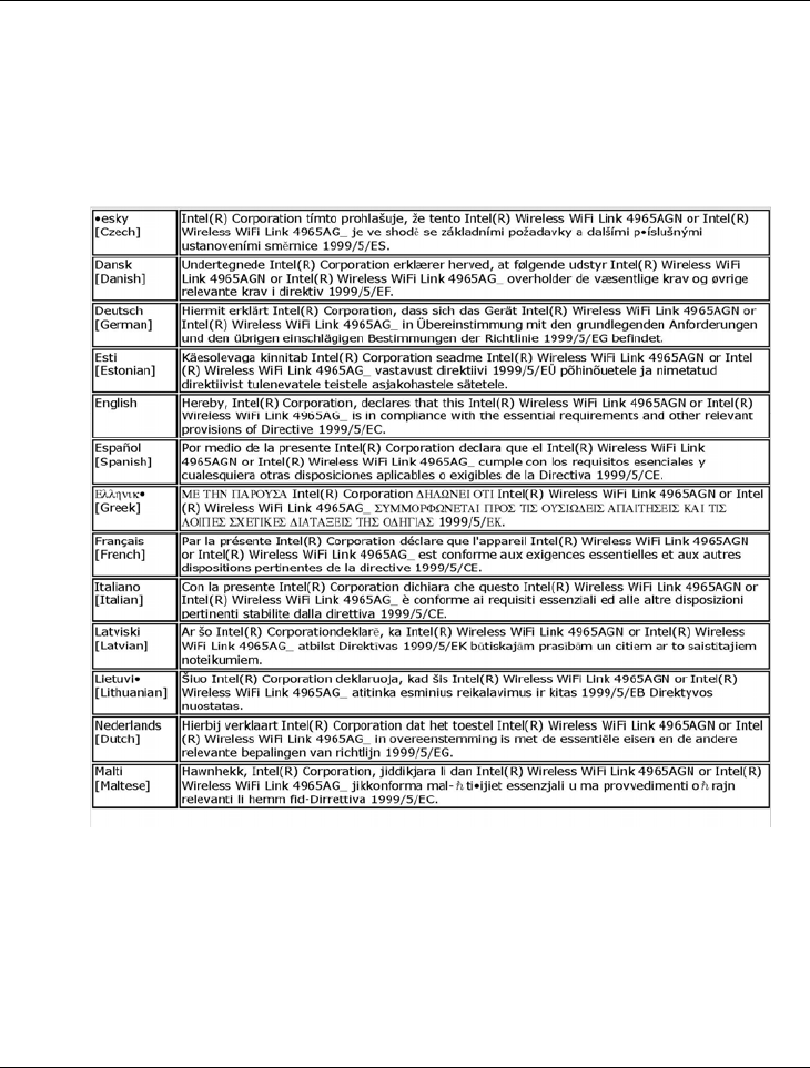
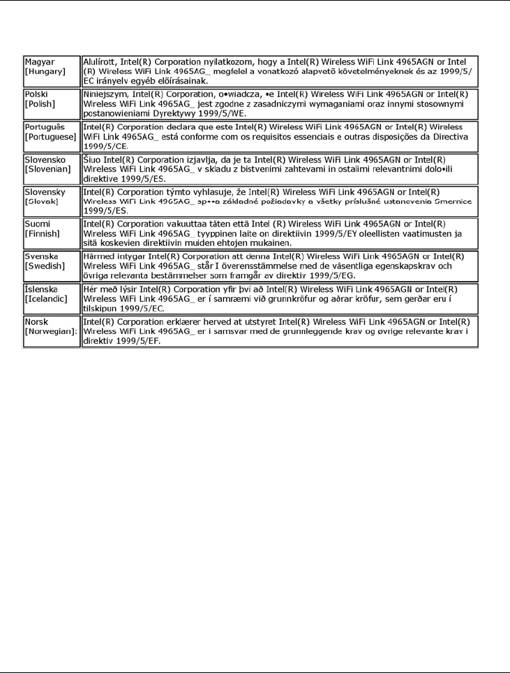
Declaration of Conformity
This equipment complies with the essential requirements of the European
Union directive 1999/5/EC.
Notebook User Guide
17
France
Pour la France métropolitain
2.400 -2. 4835 GHz (canaux 1 à 13) autorisé en usage intérieur
2.400 - 2.454 GHz (canaux 1 à 7) autorisé en usage extérieur
Pour la Guyane et la Réunion
2.400 - 2.4835 GHz (Canaux 1à 13) autorisé en usage intérieur
2.420 - 2.4835 GHz (canaux 5 à 13) autorisé en usage extérieur
Italy
A general authorization is requested for outdoor use in Italy

Notebook User Guide
18
The use of these equipments is regulated by:
1. D.L.gs 1.8.2003, n. 259, article 104 (activity subject to general authorization)
for outdoor use and article 105 (free use) for indoor use, in both cases for
private use.
2. D.M. 28.5.03, for supply to public of RLAN access to networks and
telecom services.
L’uso degli apparati è regolamentato da:
1. D.L.gs 1.8.2003, n. 259, articoli 104 (attività soggette ad autorizzazione
generale) se utilizzati al di fuori del proprio fondo e 105 (libero uso) se
utilizzati entro il proprio fondo, in entrambi i casi per uso private.
2. D.M. 28.5.03, per la fornitura al pubblico dell’accesso R-LAN alle reti e ai
servizi di telecomunicazioni.
Latvia
A license is required for outdoor use for operation in 2.4 GHz band.
Japan
Indoor use only.
Korea
Taiwan
Notebook User Guide
19
Radio Approvals
To determine whether you are allowed to use your wireless network device in a
specific country, please check to see if the radio type number that is printed on
the identification label of your device is listed in the manufacture OEM
Regulatory Guidance document.
Intel(R) PRO/Wireless 3945ABG Network Connection and
the Intel(R)PRO/Wireless 3945BG Network Connection
The information in this document applies to the following products:
Tri-mode wireless LAN adapters (802.11a/802.11b/802.11g )
Intel(R) PRO/Wireless 3945ABG Network Connection (model
WM3945ABG)
Dual-mode wireless LAN adapters (802.11b/802.11g )
Intel(R) PRO/Wireless 3945BG Network Connection (model WM3945BG)
Note Due to the evolving state of regulations and standards in the wireless
LAN field (IEEE 802.11 and similar standards), the information provided
herein is subject to change. Intel Corporation assumes no responsibility for
errors or omissions in this document. Nor does Intel make any commitment to
update the information contained herein.

Notebook User Guide
20
Information for the user
Safety Notices
The FCC with its action in ET Docket 96-8 has adopted a safety standard for
human exposure to radio frequency (RF) electromagnetic energy emitted by
FCC certified equipment. The Intel(R) PRO/Wireless 3945ABG Network
Connection adapter or the Intel(R) PRO/Wireless 3945BG Network
Connection adapter meet the Human Exposure limits found in OET Bulletin
65, supplement C, 2001, and ANSI/IEEE C95.1, 1992. Proper operation of
this radio according to the instructions found in this manual will result in
exposure substantially below the FCC’s recommended limits.
The following safety precautions should be observed:
z Do not touch or move antenna while the unit is transmitting or receiving.
z Do not hold any component containing the radio such that the antenna is
very close or touching any exposed parts of the body, especially the face or
eyes, while transmitting.
z Do not operate the radio or attempt to transmit data unless the antenna is
connected; if not, the radio may be damaged.
z Use in specific environments:
Ö The use of wireless devices in hazardous locations is limited by the
constraints posed by the safety directors of such environments.
Ö The use of wireless devices on airplanes is governed by the Federal
Aviation Administration (FAA).
Ö The use of wireless devices in hospitals is restricted to the limits set
forth by each hospital.
z Antenna use:
Ö In order to comply with FCC RF exposure limits, low gain integrated
antennas should be located at a minimum distance of 20 cm (8 inches)
or more from the body of all persons.
Ö High-gain, wall-mount, or mast-mount antennas are designed to be
professionally installed and should be located at a minimum distance
of 30 cm (12 inches) or more from the body of all persons. Please
contact your professional installer, VAR, or antenna manufacturer for
proper installation requirements.

Notebook User Guide
21
z Explosive Device Proximity Warning (see below)
z Antenna Warning (see below)
z Use on Aircraft Caution (see below)
z Other Wireless Devices (see below)
z Power Supply (Access Point) (see below)
Explosive Device Proximity Warning
Warning: Do not operate a portable transmitter (such as a wireless
network device) near unshielded blasting caps or in an explosive environment
unless the device has been modified to be qualified for such use.
Antenna Warnings
Warning: To comply with the FCC and ANSI C95.1 RF exposure limits, it
is recommended for the Intel(R) PRO/Wireless 3945ABG Network
Connection adapter or the Intel(R) PRO/Wireless 3945BG Network
Connection adapter installed in a desktop or portable computer, that the
antenna for this device be installed so as to provide a separation distance of al
least 20 cm (8 inches) from all persons and that the antenna must not be co-
located or operating in conjunction with any other antenna or radio transmitter.
It is recommended that the user limit exposure time if the antenna is
positioned closer than 20 cm (8 inches).
Warning: Intel(R) PRO/Wireless LAN products are not designed for use
with high-gain directional antennas. Use of such antennas with these products
is illegal.
Use On Aircraft Caution
Caution: Regulations of the FCC and FAA prohibit airborne operation of
radio-frequency wireless devices because their signals could interfere with
critical aircraft instruments.

Notebook User Guide
22
Other Wireless Devices
Safety Notices for Other Devices in the Wireless Network: See the
documentation supplied with wireless Ethernet adapters or other devices in
the wireless network.
Local Restrictions on 802.11a, 802.11b, and 802.11g Radio Usage
Caution: Due to the fact that the frequencies used by 802.11a, 802.11b
and 802.11g wireless LAN devices may not yet be harmonized in all countries,
802.11a, 802.11b, and 802.11g products are designed for use only in specific
countries, and are not allowed to be operated in countries other than those of
designated use. As a user of these products, you are responsible for ensuring
that the products are used only in the countries for which they were intended
and for verifying that they are configured with the correct selection of
frequency and channel for the country of use. The device transmit power
control (TPC) interface is part of the Intel(R) PROSet/Wireless software.
Operational restrictions for Equivalent Isotropic Radiated Power (EIRP) are
provided by the system manufacturer. Any deviation from the permissible
power and frequency settings for the country of use is an infringement of
national law and may be punished as such.
For country-specific information, see the additional compliance information
supplied with the product.
Wireless interoperability
The Intel(R) PRO/Wireless 3945BG Network Connection are designed to be
interoperable with other wireless LAN products that are based on direct
sequence spread spectrum (DSSS) radio technology and to comply with the
following standards:
z IEEE Std. 802.11b compliant Standard on Wireless LAN.
z IEEE Std. 802.11g compliant Standard on Wireless LAN.
z IEEE Std. 802.11a compliant Standard on Wireless LAN.
z Wireless Fidelity (WiFi) certification, as defined by the Wi-Fi Alliance.

Notebook User Guide
23
The Intel(R) PRO/Wireless 3945ABG Network Connection adapter
or the Intel(R) PRO/Wireless 3945BG Network Connection adapter
The Intel(R) PRO/Wireless 3945ABG Network Connection adapter or the
Intel(R) PRO/Wireless 3945BG Network Connection adapter, like other radio
devices, emits radio frequency electromagnetic energy. The level of energy
emitted by this device, however, is less than the electromagnetic energy
emitted by other wireless devices such as mobile phones. The Intel(R)
PRO/Wireless 3945ABG Network Connection adapter or the Intel(R)
PRO/Wireless 3945BG Network Connection adapter wireless device operates
within the guidelines found in radio frequency safety standards and
recommendations. These standards and recommendations reflect the
consensus of the scientific community and result from deliberations of panels
and committees of scientists who continually review and interpret the
extensive research literature. In some situations or environments, the use of
the Intel (R) PRO/Wireless 3945ABG Network Connection adapter or the
Intel(R) PRO/Wireless 3945BG Network Connection adapter may be
restricted to:
z Using the Intel(R) PRO/Wireless 3945ABG Network Connection adapter
or the Intel(R) PRO/Wireless 3945BG Network Connection adapter
equipment on board airplanes, or
z Using the Intel(R) PRO/Wireless 3945ABG Network Connection adapter
or the Intel(R) PRO/Wireless 3945BG Network Connection adapter
equipment in any other environment where the risk of interference with
other devices or services is perceived or identified as being harmful.
If you are uncertain of the policy that applies to the use of wireless devices in a
specific organization or environment (an airport, for example), you are
encouraged to ask for authorization to use the Intel(R) PRO/Wireless
3945ABG Network Connection adapter or the Intel(R) PRO/Wireless
3945BG Network Connection wireless devices before you turn it on.
Regulatory information
Information for the OEMs and Integrators:
The following statement must be included with all versions of this document

Notebook User Guide
24
supplied to an OEM or integrator, but should not be distributed to the end
user.
z This device is intended for OEM integrators only.
z This device cannot be co-located with any other transmitter.
z Please see to the full Grant of Equipment document for other restrictions.
z This device must be operated and used with a locally approved access
point.
Information to be Supplied to the End User by the OEM or
Integrator
The following regulatory and safety notices must be published in
documentation supplied to the end user of the product or system
incorporating an Intel(R) PRO/Wireless 3945ABG Network Connection or an
Intel(R) PRO/Wireless 3945BG Network Connection in compliance with local
regulations. Host system must be labeled with "Contains FCC ID:
XXXXXXXX", FCC ID displayed on label.
The Intel(R) PRO/Wireless 3945ABG Network Connection adapter or the
Intel(R) PRO/Wireless 3945BG Network Connection wireless network device
must be installed and used in strict accordance with the manufacturer's
instructions as described in the user documentation that comes with the
product. For country-specific approvals, see Radio approvals. Intel
Corporation is not responsible for any radio or television interference caused
by unauthorized modification of the devices included with the Intel(R)
PRO/Wireless 3945ABG Network Connection or the Intel(R) PRO/Wireless
3945BG Network Connection adapter kit, or the substitution or attachment of
connecting cables and equipment other than that specified by Intel
Corporation. The correction of interference caused by such unauthorized
modification, substitution or attachment is the responsibility of the user. Intel
Corporation and its authorized resellers or distributors are not liable for any
damage or violation of government regulations that may arise from the user
failing to comply with these guidelines.

Notebook User Guide
25
Local Restriction of 802.11a, 802.11b, and 802.11g Radio Usage
The following statement on local restrictions must be published as part of the
compliance documentation for all 802.11a, 802.11b, and 802.11g products.
Caution: Due to the fact that the frequencies used by 802.11a, 802.11b,
and 802.11g wireless LAN devices may not yet be harmonized in all countries,
802.11a, 802.11b, and 802.11g products are designed for use only in specific
countries, and are not allowed to be operated in countries other than those of
designated use. As a user of these products, you are responsible for ensuring
that the products are used only in the countries for which they were intended
and for verifying that they are configured with the correct selection of
frequency and channel for the country of use. Any deviation from permissible
settings and restrictions in the country of use could be an infringement of
national law and may be punished as such.
FCC Radio Frequency Interference Requirements
This device is restricted to indoor use due to its operation in the 5.15 to 5.25
GHz frequency range. FCC requires this product to be used indoors for the
frequency range 5.15 to 5.25 GHz to reduce the potential for harmful
interference to co-channel Mobile Satellite systems. High power radars are
allocated as primary users of the 5.25 to 5.35 GHz and 5.65 to 5.85 GHz
bands. These radar stations can cause interference with and /or damage this
device.
z This device is intended for OEM integrators only.
z This device cannot be co-located with any other transmitter.
USA—Federal Communications Commission (FCC)
This device complies with Part 15 of the FCC Rules. Operation of the device
is subject to the following two conditions:
z This device may not cause harmful interference.
z This device must accept any interference that may cause undesired
operation.
Notebook User Guide
26
Note: The radiated output power of the Intel(R) PRO/Wireless 3945ABG
Network Connection adapter or the Intel(R) PRO/Wireless 3945BG Network
Connection wireless network device is far below the FCC radio frequency
exposure limits. Nevertheless, the Intel(R) PRO/Wireless LAN wireless
network device should be used in such a manner that the potential for human
contact during normal operation is minimized. To avoid the possibility of
exceeding the FCC radio frequency exposure limits, you should keep a distance
of at least 20 cm between you (or any other person in the vicinity) and the
antenna that is built into the computer.
Interference statement
This equipment has been tested and found to comply with the limits for a
Class B digital device, pursuant to Part 15 of the FCC Rules. These limits are
designed to provide reasonable protection against harmful interference in a
residential installation. This equipment generates, uses, and can radiate radio
frequency energy. If the equipment is not installed and used in accordance with
the instructions, the equipment may cause harmful interference to radio
communications. There is no guarantee, however, that such interference will
not occur in a particular installation. If this equipment does cause harmful
interference to radio or television reception (which can be determined by
turning the equipment off and on), the user is encouraged to try to correct the
interference by taking one or more of the following measures:
z Reorient or relocate the receiving antenna.
z Increase the distance between the equipment and the receiver.
z Connect the equipment to an outlet on a circuit different from that to
which the receiver is connected.
z Consult the dealer or an experienced radio/TV technician for help.
Note: The Intel(R) PRO/Wireless 3945ABG Network Connection adapter
or the Intel(R) PRO/Wireless 3945BG Network Connection adapter wireless
network device must be installed and used in strict accordance with the
manufacturer's instructions as described in the user documentation that comes
with the product. Any other installation or use will violate FCC Part 15
regulations.

Notebook User Guide
27
Underwriters Laboratories Inc. (UL) Regulatory Warning
For use in (or with) UL Listed personal computers or compatible.
Brazil
Este equipamento opera em caráter secundário, isto é, não tem direito a
proteção contra interferência prejudicial, mesmo de estações do mesmo tipo, e
não pode causar interferência a sistemas operando em caráter primário
Canada—Industry Canada (IC)
This device complies with RSS210 of Industry Canada.
Caution: When using IEEE 802.11a wireless LAN, this product is
restricted to indoor use due to its operation in the 5.15- to 5.25-GHz
frequency range. Industry Canada requires this product to be used indoors for
the frequency range of 5.15 GHz to 5.25 GHz to reduce the potential for
harmful interference to co-channel mobile satellite systems. High power radar
is allocated as the primary user of the 5.25- to 5.35-GHz and 5.65 to 5.85GHz
bands. These radar stations can cause interference with and/or damage to this
device.
The maximum allowed antenna gain for use with this device is 6dBi in order
to comply with the E.I.R.P limit for the 5.25- to 5.35 and 5.725 to 5.85GHz
frequency range in point-to-point operation
This Class B digital apparatus complies with Canadian ICES-003, Issue 4, and
RSS-210, No 4 (Dec 2000) and No 5 (Nov 2001).
Cet appariel numérique de la classe B est conforme à la norme NMB-003, No.
4, et CNR-210, No 4 (Dec 2000) et No 5 (Nov 2001).
"To prevent radio interference to the licensed service, this device is intended
to be operated indoors and away from windows to provide maximum
shielding. Equipment (or its transmit antenna) that is installed outdoors is
subject to licensing."

Notebook User Guide
28
« Pour empêcher que cet appareil cause du brouillage au service faisant l'objet
d'une licence, il doit être utilisé a l'intérieur et devrait être placé loin des
fenêtres afinde fournir un écran de blindage maximal. Si le matériel (ou son
antenne d'émission) est installé à l'extérieur, il doit faire l'objet d'une licence. »
Europe Frequency Bands
2.400 - 2.4835 GHz (Europe ETSI)
5.15 – 5.35 GHz and 5.47 - 5.725 GHz (Europe ETSI)
Low band 5.25 – 5.35 GHz is for indoor use only
5.47 - 5.725 GHz is current not allowed in Czech Republic and France
Notebook User Guide
29
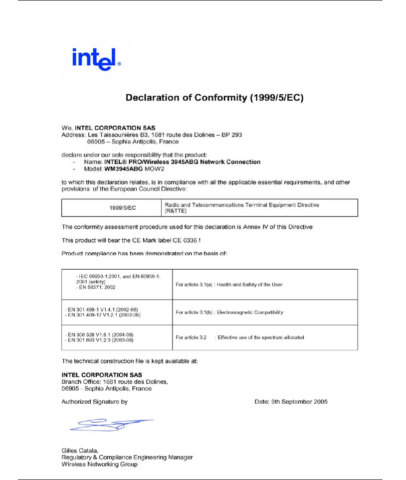
Declaration of Conformity
Notebook User Guide
30
This equipment complies with the essential requirements of the European
Union directive 1999/5/EC.
Notebook User Guide
31
France
Pour la France métropolitaine
2.400 - 2.4835 GHz (Canaux 1à 13) autorisé en usage intérieur
2.400 - 2.454 GHz (Canaux 1à 7) autorisé en usage extérieur
Pour la Guyane et la Réunion
2.400 - 2.4835 GHz (Canaux 1à 13) autorisé en usage intérieur
2.420 - 2.4835 GHz (Canaux 5 à 13) autorisé en usage extérieur
Italy
A general authorization is requested for outdoor use in Italy
Notebook User Guide
32
The use of these equipments is regulated by:
1. D.L.gs 1.8.2003, n. 259, article 104 (activity subject to general authorization)
for outdoor use and article 105 (free use) for indoor use, in both cases for
private use.
2. D.M. 28.5.03, for supply to public of RLAN access to networks and telecom
services.
L’uso degli apparati è regolamentato da:
1. D.L.gs 1.8.2003, n. 259, articoli 104 (attività soggette ad autorizzazione
generale) se utilizzati al di fuori del proprio fondo e 105 (libero uso) se
utilizzati entro il proprio fondo, in entrambi i casi per uso private.
2. D.M. 28.5.03, per la fornitura al pubblico dell’accesso R-LAN alle reti e ai
servizi di telecomunicazioni.
Latvia
A license is required for outdoor use for operation in 2.4 GHz band.
Japan
Indoor use only.
Korea
Taiwan
Notebook User Guide
33
Radio approvals
To determine whether you are allowed to use your wireless network device in a
specific country, please check to see if the radio type number that is printed on
the identification label of your device is listed in the manufacture OEM
Regulatory Guidance document.
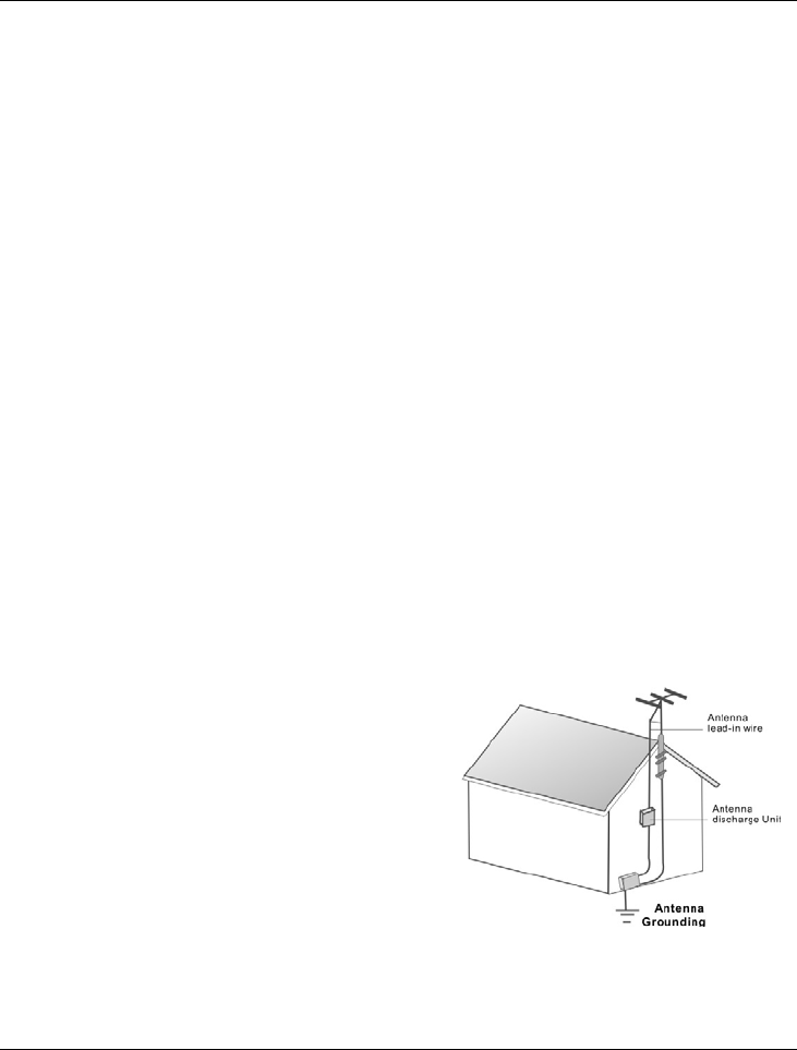
Television antenna connectors protection (for system TV
tuner card)
External television antenna grounding
If an outside antenna or cable system is to be connected to your mini EPC,
make sure that the antenna or cable system is electrically grounded to provide
some protection against voltage surges and static charges.
ANSI/NFPA 70, the National Electrical Code (NEC), in particular Section
820.93, provide information with regard to proper grounding of the mask and
supporting structure, grounding of the lead-in wire to an antenna discharge unit,
size of grounding conductors, location of antenna discharge unit, connection to
grounding electrodes, and requirements for the grounding electrode.
Lightning protection
For added protection of any product
during a lightning storm or when it is
left unattended or unused for long
periods of time, unplug the product
from the wall outlet and disconnect
the antenna or cable system.
Power Lines

Notebook User Guide
34
Do not locate the antenna near overhead light or power circuits, or where it
could fall into such power or circuits.
WARNING: When installing or realigning an outside antenna system,
extreme care should be taken to keep from touch such power lines or
circuits. Contact with them could be fatal.
Regulatory information:
Installation and use of this Wireless LAN device must be in strict accordance
with the instructions included in the user documentation provided with the
product. Any changes or modifications (including the antennas) made to this
device that are not expressly approved by the manufacturer may void the user’s
authority to operate the equipment. The manufacturer is not responsible for
any radio or television interference caused by unauthorized modification of
this device, or the substitution of the connecting cables and equipment other
than manufacturer specified. It is the responsibility of the user to correct any
interference caused by such unauthorized modification, substitution or
attachment. Manufacturer and its authorized resellers or distributors will
assume no liability for any damage or violation of government regulations
arising from failing to comply with these guidelines.
FCC RF Radiation Exposure Statement:
This equipment complies with FCC RF radiation exposure limits set forth for
an uncontrolled environment. This device and its antenna must not be co-
located or operating in conjunction with any other antenna or transmitter.
Safety Information
In order to maintain compliance with the FCC RF exposure guidelines, this
equipment should be installed and operated with minimum distance 20cm

Notebook User Guide
35
between the radiator and your body. Use only with supplied antenna.
Unauthorized antenna, modification, or attachments could damage the
transmitter and may violate FCC regulations.
This equipment complies with FCC RF radiation exposure limits set forth an
uncontrolled environment. This device was tested for typical lap-held
operations with the device contacted directly to the human body to the back
side of the notebook computer. To maintain compliance with the FCC RF
exposure requirement, avoid direct contact to the transmitting antenna during
operation.
Notebook User Guide
36
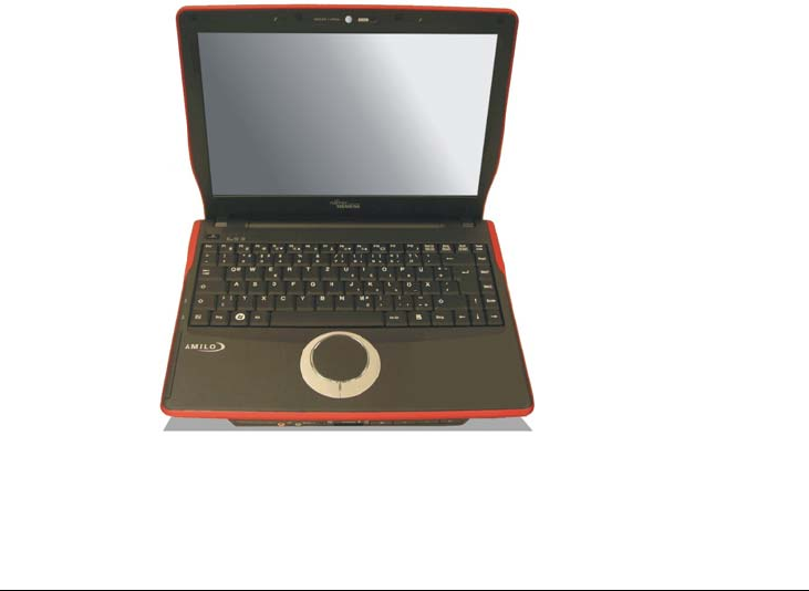
About Your Notebook Computer
Congratulation for having purchased your new Professional
Multimedia Notebook. This notebook incorporates the
strongest features, which integrate the latest technologies
available in the notebook industry.
Your new notebook computer not only drives today
multimedia applications but also be ready for tomorrow
exciting new software.
This Professional Multimedia Notebook is a freedom,
flexibility, and functionality notebook which users are
demanding for a long time.
Notebook User Guide
37
About Your User Guide
Welcome to your Professional Multimedia Notebook User
Guide. This manual covers everything you need to know in
learning how to use your computer. This manual also assumes
that you know the basic concepts of Windows and the PC. You
will start doing a lot of great and fun things with your computer.
This manual is divided into eight chapters.
Chapter 1 gives introduction on your computer features.
Chapter 2 provides step-by-step instructions to help you
begin using your notebook as quickly as possible.
Chapter 3 describes how to operate the standard features of
your computer.
Chapter 4 illustrates how to integrate video and sound chips
into impressive presentation.
Chapter 5 illustrates how to connect external device to your
computer.
Chapter 6 explains how to use the System BIOS Setup
program.
Chapter 7 explains how to use the internal module options of
your computer.
Chapter 8 offers instructions on how to care and maintain
your notebook.

Notebook User Guide
38
Table of Contents
ABOUT YOUR NOTEBOOK COMPUTER........................................ 36
ABOUT YOUR USER GUIDE............................................................... 37
1 INTRODUCTION............................................................................. 45
1.1 FEATURE HIGHLIGHT .................................................................... 46
1.2 UNPACKING THE COMPUTER ......................................................... 48
1.3 THE INSIDE OF THE NOTEBOOK ..................................................... 48
Notebook LED Indicator .............................................................. 51
1.4 THE FRONT SIDE OF THE NOTEBOOK............................................. 52
Notebook Status Icons .................................................................. 54
1.5 THE LEFT SIDE OF THE NOTEBOOK................................................ 55
1.6 THE RIGHT SIDE OF THE NOTEBOOK ............................................. 57
1.7 THE UNDERSIDE OF THE NOTEBOOK ............................................. 58
1.8 NOTEBOOK ACCESSORIES.............................................................. 60
1.9 NOTEBOOK OPTIONS ..................................................................... 61
2 GETTING STARTED...................................................................... 63
2.1 USING THE BATTERY PACK ........................................................... 64
Extending Battery Life.................................................................. 67
2.2 CONNECTING THE AC POWER SOURCE.......................................... 67
2.3 STARTING YOUR COMPUTER......................................................... 69
2.4 ADJUSTING THE DISPLAY CONTROLS ............................................ 70
2.5 INSTALLING THE NOTEBOOK DEVICE DRIVERS ............................. 70
Installing Windows Vista from Optical Disk Drive......................... 70
driver installation note:................................................................ 71
Installing the Chipset Driver........................................................ 71
Installing the VGA Device Driver................................................ 72
Installing the Audio Device Driver .............................................. 72

Notebook User Guide
39
Installing Synaptics – Touch Pad driver ...................................... 73
Installing the LAN Device Driver................................................. 73
Installing the Bluetooth Device Driver......................................... 74
Installing Camera Device Driver.................................................74
Installing CardReader Device Driver .......................................... 75
Installing the Wireless LAN Driver and Utility............................ 75
Installing the Robson Driver and Utility...................................... 76
Installing the TV-Tuner Card Device Driver ............................... 77
2.6 TURNING OFF YOUR COMPUTER.................................................... 77
3 USING YOUR NOTEBOOK........................................................... 79
3.1 STARTING YOUR OPERATING SYSTEM........................................... 80
3.2 UNDERSTANDING THE KEYBOARD FUNCTIONS.............................. 80
Basic Keyboard Functions ........................................................... 83
Cursor Control Keys..................................................................... 84
Screen Control Keys..................................................................... 84
Windows Hot Keys........................................................................ 85
Special Function Keys.................................................................. 85
3.3 USING THE TOUCHPAD POINTING DEVICE ....................................... 87
3.4 CONFIGURING YOUR SCREEN DISPLAY ......................................... 89
Possible Display Configurations.................................................. 90
Changing the Display Properties under Windows.................................. 91
3.5 KNOWING THE POWER SAVING FEATURES .................................... 91
3.6 WORKING WITH THE BUILT-IN HDD............................................... 93
3.7 HOW TO ACCESS THE OPTICAL DRIVE........................................... 93
3.8 EXPRESSCARD............................................................................... 95
What is ExpressCard ?................................................................. 95
Inserting and Removing a ExpressCard....................................... 97
3.9 USING FLASH MEMORY CARDS................................................... 100
What is Flash Memory Card? .................................................... 100
4 FUN WITH WINDOWS VISTA EXPERIENCE ........................ 103

Notebook User Guide
40
4.1 WHAT IS WINDOWS VISTA? ........................................................ 104
4.2 GET READY FOR WINDOWS VISTA .............................................. 104
4.3 ENJOY YOUR MULTIMEDIA APPLICATION ................................... 107
Internet Explorer........................................................................ 107
Windows Calendar ..................................................................... 107
Windows Contacts...................................................................... 108
Windows Defender ..................................................................... 109
Windows DVD Maker................................................................. 110
Windows Fax and Scan .............................................................. 111
Windows Live Messenger Download ......................................... 112
Windows Mail............................................................................. 113
Windows Media Center .............................................................. 114
Windows Media Player .............................................................. 115
Windows Meeting Space............................................................. 115
Windows Movie Maker............................................................... 116
Windows Photo Gallery.............................................................. 117
Windows Update......................................................................... 118
Windows Sidebar and Gadgets................................................... 119
Gaming....................................................................................... 120
Windows Flip and Windows Flip 3D ......................................... 121
5 CONNECTING TO PERIPHERALS........................................... 123
5.1 USING THE USB PORT................................................................. 124
5.2 USING THE IEEE 1394 PORT ....................................................... 125
5.3 USING THE EXTERNAL MONITOR PORT............................................... 126
5.4 USING THE ANTENNA PORT .............................................................. 128
5.5 USING THE EXTERNAL AUDIO SYSTEM ....................................... 129
5.6 USING THE LAN PORT ................................................................ 130
5.7 USING THE WIRELESS LAN......................................................... 131
6 CUSTOMIZING YOUR NOTEBOOK............................................ 133

Notebook User Guide
41
6.1 RUNNING THE BIOS SETUP PROGRAM ........................................ 134
6.2 USING THE MAIN MENU SETUP ................................................... 136
6.2.1 Primary Master Sub-Menu.............................................. 138
6.2.2 Secondary Master Sub-Menu........................................... 139
6.3 USING THE ADVANCED CMOS SETUP......................................... 140
6.4 USING SECURITY MENU SETUP ................................................... 141
6.5 USING THE BOOT SETUP .............................................................. 143
6.6 HOW TO EXIT THE SETUP PROGRAM............................................ 144
6.7 HOW TO UPGRADE THE BIOS...................................................... 145
7 USING OPTIONS ........................................................................... 147
SYSTEM UPGRADE................................................................................. 148
7.1 MEMORY UPGRADE..................................................................... 148
Installing Memory Module ......................................................... 149
7.2 HARD DISK UPGRADE.................................................................. 150
7.3 WIRELESS MODULE INSTALLATION............................................. 151
8 CARING FOR YOUR NOTEBOOK............................................ 153
8.1 IMPORTANT SAFETY INSTRUCTIONS ............................................ 154
8.2 CLEANING YOUR COMPUTER....................................................... 156
8.3 MAINTAINING THE LCD QUALITY............................................... 157
8.4 MAINTAINING YOUR HARD DISK ................................................ 157
8.5 BATTERY CARE GUIDELINES ....................................................... 158
8.6 WHEN YOU TRAVEL.................................................................... 159
APPENDIX A SYSTEM SPECIFICATION...................................... 161
Processor Unit............................................................................ 162
System Memory........................................................................... 162
LCD Display............................................................................... 162
VGA System ................................................................................ 162
Storage........................................................................................ 163

Notebook User Guide
42
Audio System .............................................................................. 163
ExpressCard............................................................................... 163
Touchpad.................................................................................... 163
Keyboard .................................................................................... 164
Flash BIOS ................................................................................. 164
I/O Ports..................................................................................... 164
Wireless devices ......................................................................... 164
AC/DC Power Supply Adapter................................................... 164
Battery ........................................................................................ 164
Weight and Dimension ............................................................... 165

Notebook User Guide
43
This page is intended to be blank.
Introduction1
45
1 Introduction
Your Notebook PC is a fully Windows compatible
portable personal computer. With the latest features
in mobile computing and multimedia technology, this
notebook makes a natural traveling companion. With
leap of technology and compact, your Notebook PC
runs on a whole wide range of general business,
personal productivity, entertainment, and professional
applications. It is ideal for use in the office, at home,
and on the road.
Your Notebook PC makes an ideal choice for use in
the office, the schoolroom, at home, on the road and
all other occasions.

Notebook User Guide
46
1.1 Feature Highlight
Before we go to identify each part of your Notebook PC, we will first
introduce you to other notable features of your computer.
Processing Unit
• Your notebook runs on Intel® CoreTM 2 Duo processor that is integrated
with 2MB or 4MB L2 Cache. Check with your dealer on the CPU type and
speed.
• Fully compatible with an entire library of PC software based on operating
systems such as Windows Vista.
Memory
This notebook provides two memory slots for installing DDRII SDRAM 200-
pin SODIMM modules up to 4GB using 512MB, 1024MB or 2048MB DDRII
SDRAM modules.
Wide Screen LCD Display
Provides extraordinary 13.3" WXGA 1280 x 800 wide screen LCD display. It is
the best choice for you to watch DVD movie.
Wireless LAN
Intel® Wireless WiFi Link 4965AGN Network Connection (802.11a/b/g/n),
Mini Card.
Graphic System
Provides blazing graphics controller embedded in Intel GM965 chipset.

Introduction1
47
Optical Disk Drive
Provides DVD Dual or DVD Super-Multi optical disk drive..
IEEE 1394
Provides one IEEE 1394 port for fast data transmission by external hard disk
or digital video (DV).
USB 2.0
Provides three USB2.0 ports for fastest I/O data transmission.
Audio System
Compliant with Intel HD Audio (Azalia). Sound Blaster compatible. Support
32-bit, multi-channel audio system output.
Flash BIOS
Flash BIOS allows you to easily upgrade the System BIOS using the Phoenix
Flash utility program.
Power and System Management
• Integrated SMM (System Management Mode) on system chipset that shuts
down components not in use to reduce power consumption. To execute
power management, you can set up the parameter in Power Options
properties by pointing your mouse to Control Panel of Windows.
• Closing the Notebook computer (lowering the cover) allows you to
suspend the system operation instantly and resume at the press of the
power button.
• System Password for User and Supervisor included on the BIOS SETUP
Program to protect unauthorized use of your computer.

Notebook User Guide
48
1.2 Unpacking the Computer
Your computer comes securely packaged in a sturdy cardboard shipping
carton. Upon receiving your computer, open the carton and carefully remove
the contents. In addition to this User Guide, the shipping carton should also
contain the following items:
; The Notebook Computer
; An AC Adapter and AC Power Cord
; Li-Ion Battery Pack
; CD Driver Utility/ User Guide
; Quick Setup Manual
Carefully inspect each component to make sure that nothing is missing and/or
damaged. If any of these items is missing or damaged, notify your dealer
immediately. Be sure to save the shipping materials and the carton in case you
need to ship the computer or if you plan to store the computer away sometime
in the future.
1.3 The Inside of the Notebook
The notebook computer is compact with features on every side. First, look
at the inside of the system. The following sections describe inside features.
Introduction1
49
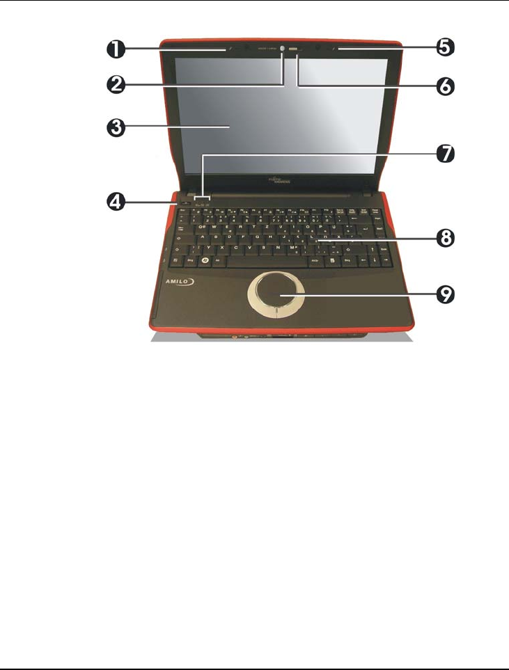
1. 5. Integrated Microphone 2. Webcam.
3. Color Widescreen LCD Display 4. Power On/Resume Button
6. Webcam Switch 7. LED Indicators
8. Keyboard 9. Touchpad Pointing Device
• Integrated Microphone
Integrated mono microphone for instant voice recording and
simultaneous voice conversation.
• Webcam
The Webcam is 1300K pixels. It can be used as a communication device
that transmits instant image through network for conference.
• Color Widescreen LCD Display
The notebook computer comes with a color LCD that you can adjust for a
comfortable viewing position. The LCD is 13.3” TFT color LCD with

Notebook User Guide
50
1280x800 (Wide XGA) resolution panels. The features of the Color LCD
Display are summarized as follows:
TFT color LCD with Widescreen 13.3” 1280x800 (Wide XGA)
resolution panels.
Capable of displaying 16M colors (32-bit true color).
LCD display control hot-keys allows you to adjust the brightness of
the LCD.
Simultaneous display capability for LCD and external desktop
computer monitor.
• Power On/Resume Button
Switches the computer power on and off, or resumes whenever it is in
Suspend mode.
• Webcam Switch
To disable or enable the Webcam function. For closing this function, push
the switch to the left side; for turning on this function, push the switch to
the right side.
• LED Indicators
Keeps you informed of your notebook computer’s current status of
Bluetooth/Wireless LAN accessing, Numeric Lock and Caps Lock.
Description of the status appears in the latter part of this section.
• Keyboard
Standard QWERTY-key layout and full-sized 87 keys keyboard with
Windows system hot-keys, embedded numeric keypad, 11 hot keys,
inverted "T" cursor arrow keys, and separate page screen control
keys.
Wide extra space below the keyboard panel for your wrist or palm to
sit-on comfortably during typing.
Introduction1
51
• Touchpad Pointing Device
Microsoft mouse compatible with two touchpad click buttons. The two
select buttons located at each side support tapping selection and dragging
functions. These buttons work like a standard computer mouse. Simply
move your fingertip over the touchpad to control the position of the
cursor. Use the selection buttons below the touchpad to select menu
items.
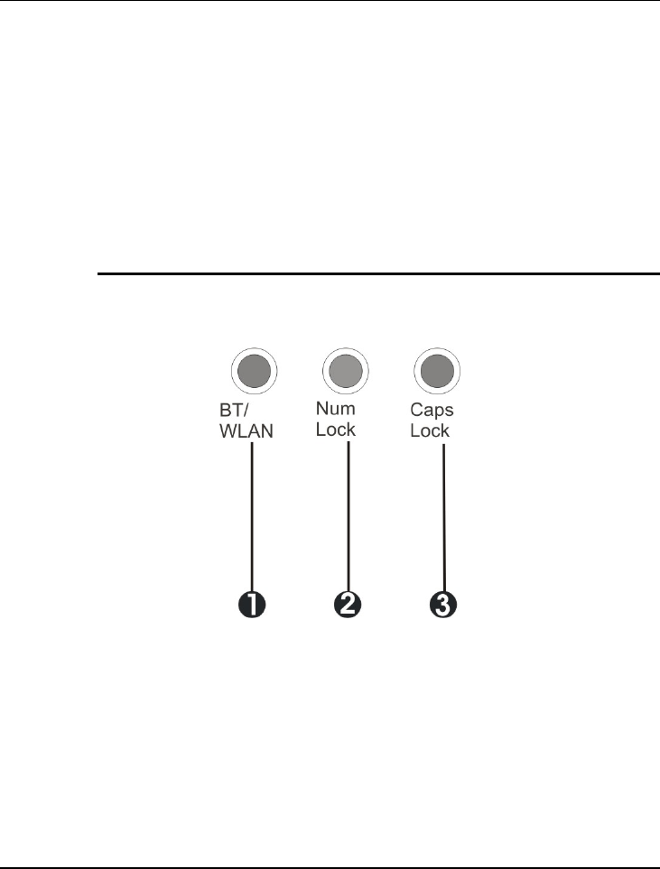
NOTEBOOK LED INDICATOR
The Status LED keeps you informed of your notebook computer’s current
status of Bluetooth/Wireless LAN accessing, Numeric Lock and Caps Lock.
1. Wireless LAN/Bluetooth 2. Num Lock 3. Caps Lock
• Wireless LAN/Bluetooth
When LED in blue light indicates that the Wireless LAN/Bluetooth
Function is activated. When activate, the system will search the wireless
LAN signal automatically if you had installed the driver.
• Num Lock
Notebook User Guide
52
When LED in blue light indicates that the Num Lock key on the keyboard
is activated. When activated, the embedded numeric keypad will be
enabled.
• Caps Lock
When LED in blue light indicates that the Caps Lock key on the keyboard
is activated. When activated, all alphabet keys typed in will be in uppercase
or capital letters.
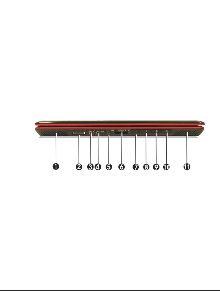
1.4 The Front Side of the Notebook
1. 11. Built-in Stereo Speakers 2. LED Indicators
3. Microphone Jack 4. Headphone Jack
5. IEEE1394 6. 4 in 1 card slot
7. Volume-Down Button 8. Volume-Up Button
9. Mute/Resume Button 10. Play/Pause Button
• Built-in Stereo Speakers
Integrated left and right mini stereo speakers for sound and audio output
for your multimedia presentations or listening pleasure.

Introduction1
53
• LED Indicators
Keeps you informed of your notebook computer’s current operating
status. Description of the status icons appears in the latter part of this
section.
• Microphone Jack
Allows you to connect an external microphone for monophonic sound
recording directly into your notebook computer.
• Headphone Jack (with SPDIF out)
Lets you plug in a stereo headphone, powered speakers, or earphone set
with 1/8 inch phono plug for personal listening. (The SPDIF transmits
digitized audio signal by optical fiber. The external audio amplifier can get
the best audio quality without loss.)
• Line-In Jack
Lets you connect audio sources, such as external CD, players to this jack
for recording on your computer or playback through the Line-Out device.
• IEEE 1394
IEEE 1394 port is a high speed I/O port that can transfer high levels of
data in real-time, such as external hard disk, Digital Video Camera.
• 4 in 1 card slot
The card slot supports SD, MMC, MS (Memory Stick) and MS_Pro flash
memory card format. You can use either of the 4 types flash memory
cards for extra storage media. Please pay attention to correct direction
when you insert the flash memory card. For more detail of flash card, you
can refer to Chapter 3.9
• Easy buttons for music listening
There are four easy buttons for your listening pleasure.
Volume-Down Button
Decreases the audio volume of the music incrementally.
Notebook User Guide
54
Volume-Up Button
Increases the audio volume of the music incrementally.
Mute/Resume Button
Press this button to shut down or resume the music.
Play/Pause Button
Press this button to play or pause the music.
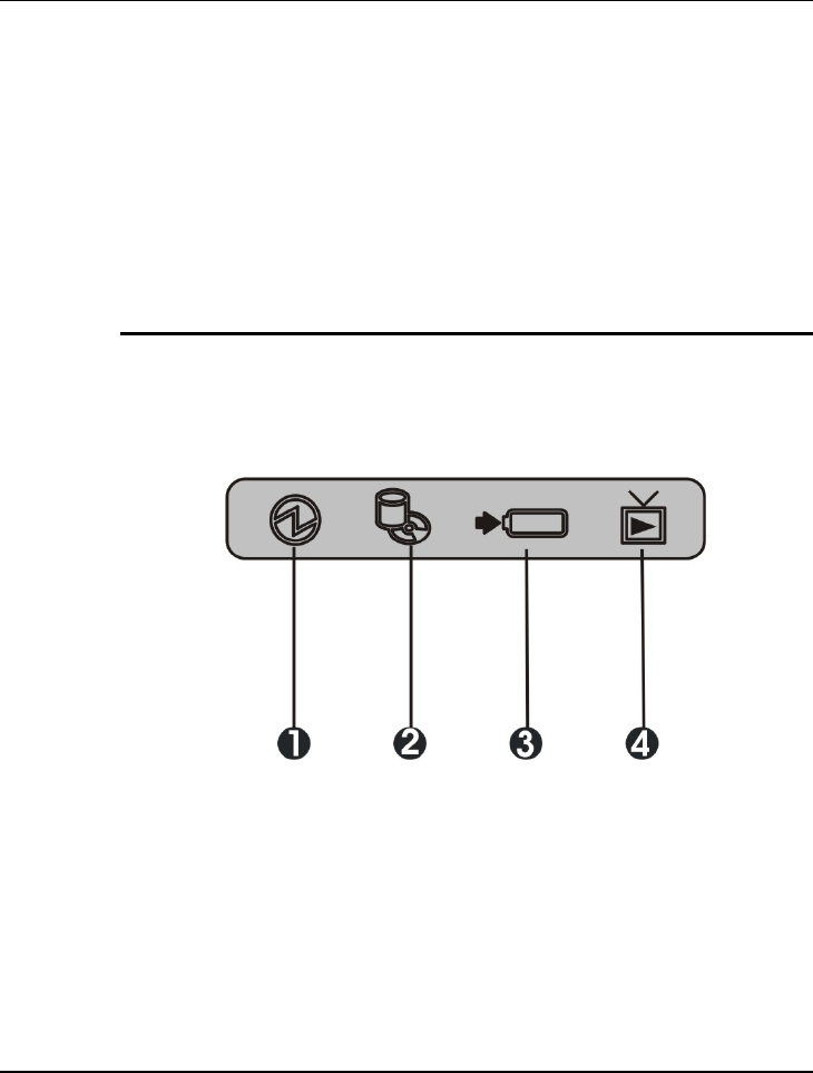
NOTEBOOK STATUS ICONS
The Status LED Panel keeps you informed of the notebook’s current power
and operating status. Each LED is marked with an icon to designate the
system status.
1. Power Indicator 2. Drive Access
3. Battery Charging LED 4. TV Access
• Power Indicator
Lets you know that power to the system is turned on. This LED is
positioned so that you can see the power state whether the LCD panel is
opened or closed.
Lights blue when the system is powered on.

Introduction1
55
Lights blue blinking when the system is in Standby mode.
Lights yellow when the battery power is low.
Lights orange when the battery power is critical low.
• Battery Charging LED
Lights to indicate battery in charging status.
Lights orange to indicate that the battery is in charging.
Lights orange blinking when the battery charging is in error.
Lights blue to indicate the battery is fully charged or no battery
installed.
• Drive Access
When LED in blue blinking light indicates that the system is accessing the
Hard Disk or Optical Disk Drive.
• TV Access
When LED in blue light indicates that the system is accessing the TV
channel.
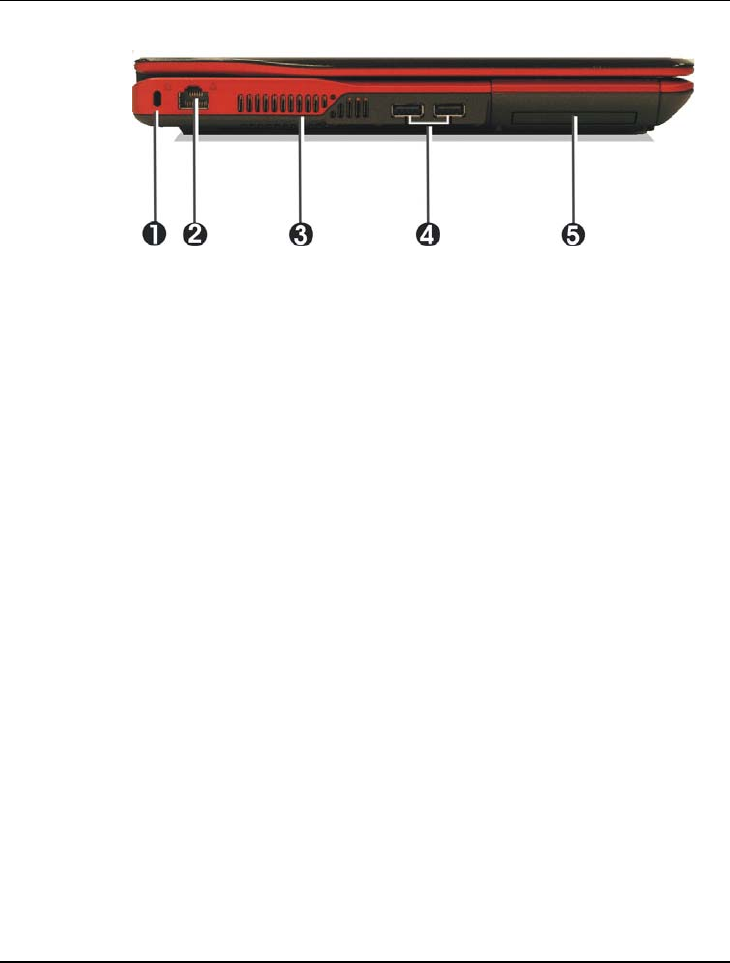
1.5 The Left Side of the Notebook
The left side of your notebook computer provides the features shown in the
following figure.
Notebook User Guide
56
1. Locking Device Keyhole 2. LAN Port
3. Air-Outlet Vent 4. USB 2.0 Ports
5. ExpressCard Slot
• Locking Device Keyhole
Lets you attach a Kensington security system or a compatible lock to
physically secure your notebook computer.
• LAN Port
An internal 10Base-T/100Base-TX Ethernet LAN module connects your
computer to other computers/networks through a local area network
(LAN).
• Air-Outlet Vent
Emits the heat out of your computer and keeps it within operating
temperature.
• USB 2.0 Ports
The Universal Serial Bus (USB) port allows you to connect USB 2.0-
compliant devices (for example, printers, scanners and so on) to your
notebook computer.
• ExpressCard Slot
Introduction1
57
A newly developed PC Card interface, its connector has 26 pins and has a
potential transfer rate of up to 500 MB/sec (or 250 MB/sec in each
direction).
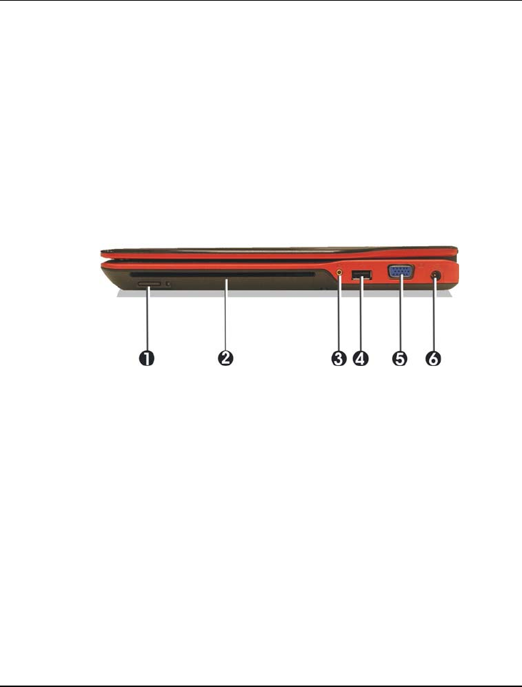
1.6 The Right Side of the Notebook
The right side of the notebook computer offers the features shown in the
following figure.
1. Eject Button 2. Optical Disk Drive
3. Antenna Port 4. USB 2.0 Port
5. VGA Port 6. DC Power Port
Right Side Features
• Eject Button
Push the eject button found on the left side of the Optical Disk Drive slot
to release the Optical Disk.
• Optical Disk Drive
Allows you to load and start programs from a compact disc (CD) or a
digital video disc (DVD) and play conventional audio CDs. It also can
make CD/DVD by using CD-R/RW or DVD-R/RW.
Notebook User Guide
58
• Antenna Port
Allows you to connect the antenna for accessing the TV channel for TV
watching..
• USB 2.0 Port
The Universal Serial Bus (USB) port allows you to connect USB 2.0-
compliant devices (for example, printers, scanners and so on) to your
notebook computer
• VGA Port
Lets you attach an external monitor or projector for wider display. You
can run the LCD display and the external monitor simultaneously or
switch it to monitor only using the display hot-key.
• DC Power Port
Lets you connect the AC power adapter in supplying continuous power to
your notebook and recharging the battery.
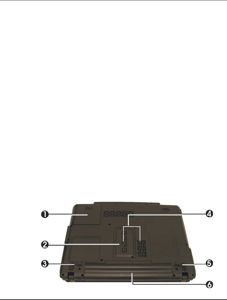
1.7 The Underside of the Notebook
The bottom of the notebook computer offers the following features.

Introduction1
59
1. Hard Disk Compartment 2. Memory Compartment
3. Battery Lock Latch 4. Air-Outlet Vent
5. Battery Release Latch 6. Battery Bay
Bottom of the System
• Hard Disk Compartment
Open this cover of this compartment to replace with other Hard Disk
Drive. Please refer to Chapter 7 for how to replace it.
• Memory Compartment
There are two SO-DIMM memory slots. One memory slot is empty for
upgrade usage.
• Battery Lock Latch
Push the latch to the lock side to lock and secure the battery, or push the
latch to the unlock side for unpacking the battery pack.
• Air-Outlet Vent
Emits the heat out of your computer and keeps it within operating
temperature.
• Battery Release Latch
To release the battery, first locate the Battery Lock Latch at the left side
with unlock status, then push the Battery Release Latch to the right end to
remove the battery pack.
• Battery Bay
Equipped with a choice of Lithium-Ion (Li-Ion) battery pack.

Notebook User Guide
60
1.8 Notebook Accessories
AC Adapter
The AC Adapter supplies external power to your notebook computer and
charges the internal battery pack simultaneously. The AC adapter has an auto-
switching design that can connect to any 100VAC ~ 240VAC power outlets.
You just change the power cord if you are going to use your notebook in other
countries with different connector outlets.
When you connect the AC adapter, it charges the battery whether or not the
notebook computer is powered on.
Battery Pack
Aside from the AC adapter, your computer can also be powered through the
internal battery pack. The battery pack uses rechargeable Lithium-Ion (Li-Ion)
battery cells that provide long computing hours when fully charged and power
management enabled. You should always leave the battery inside your
computer even when using the AC adapter as it also acts as a back-up power
supply in case power from the AC adapter is cut off. It is also very important
to have the battery pack always charged to prevent battery cell degradation.

Introduction1
61
1.9 Notebook Options
DVD dual (Dual Rewritable DVD combo) Device Pack
This device pack combines following two standard packs. Using the suitable
media, you can make any format of CD or DVD as you want.
DVD-RW combo:
This device pack can write data to CD-R or CD-RW and DVD-R or DVD-
RW media and also can read DVD/CD title. This media is commonly used on
DVD video player.
DVD+RW combo:
This device pack can write data to CD-R or CD-RW and DVD+R or
DVD+RW media for you to backup the data and also can read DVD/CD
title. This media is commonly used on newer DVD video player.
Getting Started 2
63
2 Getting Started
Your Notebook is designed and pre-configured for
easy setup and use. This chapter describes the
installation steps you should follow to get the
notebook up and running as quickly as possible.
Contact your dealer if they have pre-installed all the
needed drivers to fully operate your computer or if
there is an update on the driver installation of the
notebook.

Notebook User Guide
64
2.1 Using the Battery Pack
The notebook is designed to operate with one of the following power sources:
• With AC power using the AC adapter connected to an electrical outlet.
• With a Lithium-Ion (Li-Ion) battery pack.
You should use the AC adapter whenever it is possible, relying on the battery
pack only when AC power is unavailable.
Before you use your notebook computer, install and recharge the battery pack
first. The rechargeable Li-Ion battery pack allows you to operate the notebook
without an external power source. When you connect the AC power adapter,
the battery immediately starts to recharge. Normal battery charging time is 2
hours for Lithium-Ion (Li-Ion) battery pack when your computer is turned off.
For maximum battery performance, fully discharge the battery first before
recharging it when you start to use it first time. To do so, unplug the AC
adapter, turn off power management features (through Setup and Windows),
and turn on the system. Once the battery is fully discharged, plug in the AC
adapter and recharge the battery.
If you do not discharge the battery completely, it fails to accept a full recharge.
Li-Ion battery is vulnerable, do not charge it with other power adapter, or it
may cause fire or explosion.
Risk of explosion if battery is replaced by an incorrect type. Dispose of used
batteries according to the instructions.
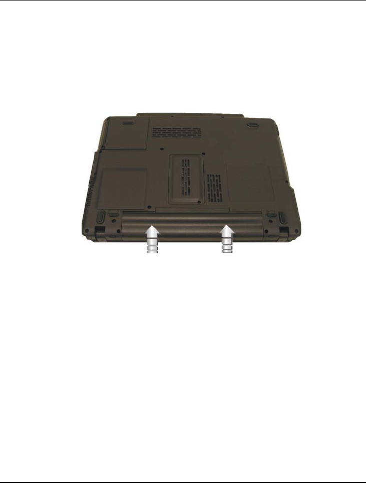
Getting Started 2
65
Installing the Battery Pack
This notebook provides the most convenient way to install the battery pack
into your computer. With the extended nose directed toward the
compartment, insert and push the battery pack.
Removing the Battery Pack
To remove the battery pack, slide the lock latch to the end of left side to
unlock the battery lock latch (1), and slide the battery release latch to the end
of right side to release the battery latch (2), then take out the battery pack with
your finger (3).
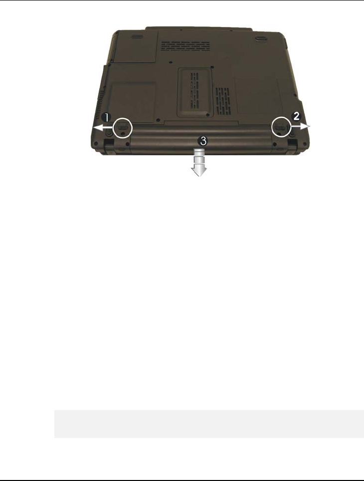
Notebook User Guide
66
Replacing the Battery Pack
When your notebook estimates that the battery only has enough charge to
continue for a few minutes, it will alert you with a battery low warning beep. If
you are consuming a lot of power by using the audio system, the PCMCIA
slots, the hard disk drives, and optical disk drive, your notebook might run out
of charge much sooner than you expect. You should always respond to the
battery low indication by connecting to AC power or turning off your
notebook, or suspending your notebook to disk. If you do not do so, the
notebook will automatically suspend to disk and turn off. The contents of the
memory will store in the hard disk drive. You will be unable to restart the
notebook until you have connected to the AC adapter or installed a charged
battery. To replace the battery pack, refer to the previous sections on
"Installing the Battery Pack" and "Removing the Battery Pack."
Be sure to save your data before replacing the battery pack or connecting
the AC adapter. Failure to do so can result in data loss.

Getting Started 2
67
EXTENDING BATTERY LIFE
It is important to be aware of the simple things for extending the life of the
system main battery while you are on the road. You should find a working
place where the external lighting is not too bright and turn down the screen
brightness. Also, you can choose the available mode on the Power
Management item of the Control Panel in Windows.
2.2 Connecting the AC Power Source
The AC adapter provides external power source to your computer and charges
the internal battery pack at the same time. The AC adapter also has an auto-
switching design that can connect to any 100VAC ~ 240VAC power outlets.
To connect the power adapter:
1. Plug the AC power cord into the power socket of the AC power adapter.
2. Plug the other end of the AC power cord to a live AC wall outlet.
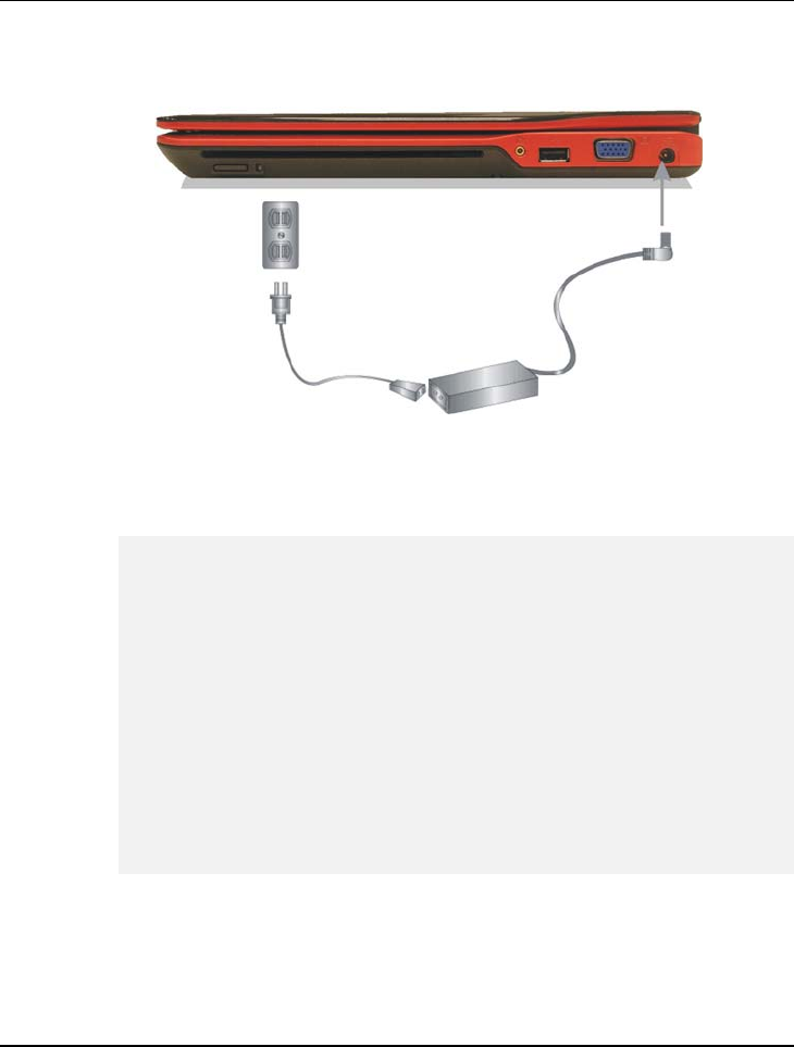
Notebook User Guide
68
3. Plug the connector of the AC adapter to the DC-IN port found at the rear
side of the computer.
Whenever possible, it is advisable to always have the AC adapter connected
to the notebook and the battery pack installed. This ensures continuous
power supply and prevents any data loss incurring from sudden power
breakdown.
y For the power supply of this equipment, an approved power cord has to
be used.
y Make sure the socket and any extension cord(s) you use can support
the total current load of all the connected devices.
y Before cleaning the computer, make sure it is disconnected from any
external power supplies (i.e. AC adapter).
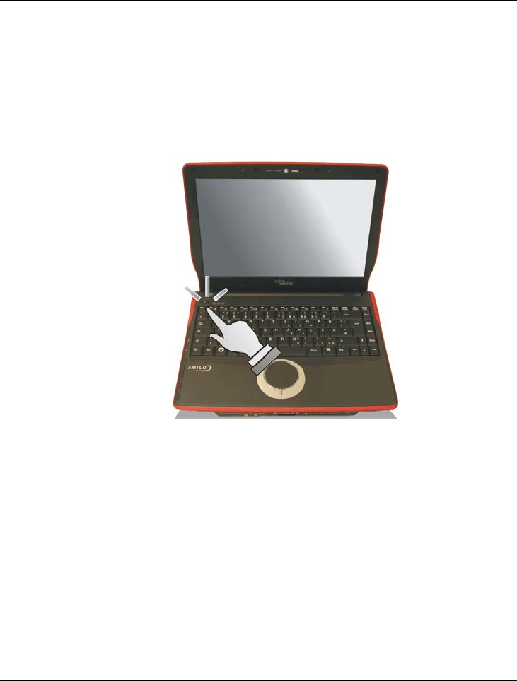
Getting Started 2
69
2.3 Starting Your Computer
The Power/Resume button is found on the top of the base unit. Press the
Power/Resume button to start your computer and check that if the Power
LED turns on.
After a few seconds, the computer’s display will turn on and your computer
will begin to execute the Power On Self Test or POST to check if all system
components are running properly. Any error found during the test will be
displayed on the screen and may generate short beep sound as well.
After the test, the screen will also display a message "press <F2> to enter
SETUP". You don’t need to run this program at the moment as your dealer
already made the necessary settings for your computer optimal operation.
Refer to Chapter 6 on running the SETUP program later.
After the test has completed, your computer will start to search and boot up
the operating system from your hard drive. The notebook computer normally

Notebook User Guide
70
comes with a Windows operating system pre-installed in your hard drive.
Consult the Windows manual on how to use the program. If not, contact your
dealer for assistance.
2.4 Adjusting the Display Controls
The LCD brightness adjustment is controlled by <Fn> +<F8> and <Fn> +
<F9> keys respectively. You need to press these hot-key controls after
powering on your notebook to suit your viewing pleasure.
The Brightness hot-key control adjusts the brightness on the LCD. The
brightness hot-key control will not set the LCD completely dark or bright; it
provides sufficient lighting to the LCD to match the external lighting of the
surrounding. The brighter the room, the more you need to increase the
brightness of the LCD.
2.5 Installing the Notebook Device
Drivers
If you already have an operating system installed into your notebook
computer, it is best to install the needed device drivers for using the built-in
devices of your computer. Before installing the drivers, check with your dealer
first if they have already installed all the drivers along with the operating
system. If not, follow the procedures below:
INSTALLING WINDOWS VISTA FROM OPTICAL DISK DRIVE
To install Windows Vista directly from your optical disk drive, please go to
Boot menu of BIOS setup menu. Use arrow key to select "CD-ROM Drive",
then use "+" or "-" to move it to the top. Go to Exit menu and select "Exit

Getting Started 2
71
Saving Changes". Accordingly, insert the Windows Vista installation CD into
optical disk drive with following the instructions on the screen to finish the
installation.
DRIVER INSTALLATION NOTE:
Please be notified that you should install the CHIPSET Driver first before
installing other driver utilities.
INSTALLING THE CHIPSET DRIVER
Your notebook computer uses this advanced chipset to enhance the stability
and performance. Following is the procedure for installing the chipset driver:
Installing Chipset device driver for Windows Vista 32
1. Click the Start button, then point to Run. The Run dialog box appears.
2. Click the Browse button and specify the directory as
"E:\Drivers\Vista 32\Chipset\Setup.exe".
3. When screen appears the User Account Control window, click “Allow”
for processing the further step.
4. Click "Next" continuously to install this driver when screen displays this
command.
5. Click “Yes” to accept the License Agreement.
6. Click “Next” to continue the following step.
7. Tick the option "Yes, I want to restart my computer now.", and press
"Finish" to restart your system.

Notebook User Guide
72
INSTALLING THE VGA DEVICE DRIVER
Following is the procedure for installing the Video Accelerator 3D Adapter
VGA driver to your computer:
Installing VGA device driver for Windows Vista 32
1. Click the Start button, then point to Run. The Run dialog box appears.
2. Click the Browse button and specify the directory as.
"E:\Drivers\Vista32\VGA\Setup.exe".
3. When screen appears the User Account Control window, click
“Continue” for processing the further step.
4. Click “Next” to install this driver when screen displays this command.
5. Click “Yes” to accept the License Agreement.
6. Click “Next” to continue the following step.
7. Tick the option "Yes, I want to restart my computer now.", and press
"Finish" to restart your system.
INSTALLING THE AUDIO DEVICE DRIVER
Your notebook computer uses the Conexant Audio controller:
Installing Audio device driver for Windows Vista 32
1. Click the Start button, then point to Run. The Run dialog box appears.
2. Click the Browse button and specify the directory as.
"E:\Drivers\Vista32\Audio\Setup.exe"
where the audio driver is located.
3. When screen appears the User Account Control window, click
“Continue” for processing the further step.

Getting Started 2
73
4. Click "OK" to continue the following steps.
5. Tick the "OK" and then restart your system to finish the installation.
INSTALLING SYNAPTICS – TOUCH PAD DRIVER
Installing Synaptics - Touchpad driver for Windows Vista 32
1. Click the Start button, then point to Run. The Run dialog box appears.
2. Click the Browse button and specify the directory as.
"E:\Drivers\Vista32\Touch Pad\Setup.exe".
3. When screen appears the User Account Control window, click
“Continue” for processing the further step.
4. Click "Next" to continue the following step.
5. Click "Finish" and then press "Restart Now" to restart your system
INSTALLING THE LAN DEVICE DRIVER
Please follow the procedures below for installing the LAN driver.
Installing LAN driver for Windows Vista 32
1. Click the Start button and then click Run. The Run dialog box appears.
2. Click Browse button and specify the directory as
“E:\Drivers\Vista32\LAN\Autorun.exe "
3. Click “Install Drivers and Software” to continue the following steps.
4. When screen appears the User Account Control window, click
“Continue” for processing the further step.
5. Click “Next” to continue the following steps.
6. Choose “I accept the terms in the license agreement” and click

Notebook User Guide
74
“Next”.
7. Click “Next” to continue the following steps.
8. Click “Install” to implement the setup program to install this driver.
9. Click “Finish” and then press “Exit” to complete the installation.
INSTALLING THE BLUETOOTH DEVICE DRIVER
Please follow the procedures below for installing the Bluetooth driver:
Installing Bluetooth driver for Windows Vista 32
1. Click the Start button, then point to Run. The Run dialog box appears.
2. Click the Browse button and specify the directory as
"E:\Drivers\Vista32\Bluetooth\Setup.exe".
3. When screen appears the User Account Control window, click
“Continue” for processing the further step.
4. Click “Next” to continue the following steps.
5. Choose “I accept the terms in the license agreement” and click
“Next”.
6. Click “Install” to implement setup program to install this driver.
7. Click “Finish” and then press “Yes” to restart your system
INSTALLING CAMERA DEVICE DRIVER
Please follow the procedures below for installing the Camera Device Driver:
Installing Camera Device Driver for Windows Vista 32
1. Click the Start button, then point to Run. The Run dialog box appears.

Getting Started 2
75
2. Click the Browse button and specify the directory as.
"E:\Drivers\Vista32\Camera\setup.exe"
3. When screen appears the User Account Control window, click
“Continue” for processing the further step.
4. Click “Next” to continue the following steps.
5. Tip the option “Yes, I want to restart my computer now” to finish the
installation.
INSTALLING CARDREADER DEVICE DRIVER
Please follow the procedures below for installing the CardReader Device
Driver:
Installing CardReader Device Driver for Windows Vista 32
1. Click the Start button, then point to Run. The Run dialog box appears.
2. Click the Browse button and specify the directory as.
"E:\Drivers\Vista32\CardReader\setup.exe"
3. When screen appears the User Account Control window, click
“Continue” for processing the further step.
4. Click “OK” to complete the installation.
INSTALLING THE WIRELESS LAN DRIVER AND UTILITY
Please follow the procedures below for installing the Wireless LAN Adapter
driver:
Installing Wireless LAN driver and Utility for Windows Vista 32
1. Click the Start button, then point to Run. The Run dialog box appears.

Notebook User Guide
76
2. Click Browse button and specify the directory as
“E:\Drivers\Vista32\Wireless LAN\Autorun.exe”
3. When screen appears the User Account Control window, click
“Continue” for processing the further step.
4. Click "Install Software" to execute the setup program.
5. Tick the option “I accept the terms in the license agreement”, and
click Next for further step processing.
6. Tick the option “Typical”, and click “Next” again.
7. Click “OK” to complete the installation.
INSTALLING THE ROBSON DRIVER AND UTILITY
Please follow the procedures below for installing the Robson driver:
Installing Robson driver and Utility for Windows Vista 32
1. Click the Start button and then click Run. The Run dialog box appears.
2. Click Browse button and specify the directory as
“E:\Drivers\Vista32\Robson\setup.exe”
3. When screen appears the User Account Control window, click “Allow”
for processing the further step.
4. Click “Next” continuously to install this driver when screen displays this
command.
5. Click “Yes” to accept the License Agreement.
6. Click “Next” to continue the following step.
7. When screen appears the Windows Security window, click “Install” for
processing the further step.

Getting Started 2
77
8. Click “Next” again.
9. Tick the option "Yes, I want to restart my computer now.", and press
“Finish” to restart your system.
INSTALLING THE TV-TUNER CARD DEVICE DRIVER
Please follow the procedures below for installing the TV-Tuner Card Device
Driver:
Installing TV-Tuner Card Device Driver for Windows Vista 32
1. Click the Start button, then point to Run. The Run dialog box appears.
2. Click the Browse button and specify the directory as.
"E:\Drivers\Vista32\TV
Driver\A306_Vista_Drv_x86_V1.12.0.60_Install"
3. When screen appears the User Account Control window, click “Allow”
to complete the installation.
2.6 Turning off Your Computer
If you are not going to use the computer for a while, it is best to turn off the
power of the computer for longer use. Before turning off the power, you need
to close first all application programs and shutdown the operating system.
After turning off the computer, make it a habit to leave the LCD panel open
for a while whenever used for an extended period of time. This allows the
inside parts of the computer to cool off. Closing the panel will force the heat
up against the LCD screen, which may degrade the LCD when done regularly.
More importantly, never close the LCD panel for a long period of time when
computer is on and power saving features are disabled.

Notebook User Guide
78
Using Your Notebook 3
79
3 Using Your Notebook
This chapter describes how to operate the standard
built-in features of the notebook that you normally would
use in your day-to-day computer work. If you are new to
computers and to your operating system, you also need to
read the manual for the operating system on how to work
with your computer. It is very important to familiarize
yourself well with the operating system. The succeeding
chapters not only guide you to go beyond the basics, but
also try other exciting features.

Notebook User Guide
80
3.1 Starting Your Operating System
The operating system is a must ingredient in using your computer. Without an
operating system, it is like playing chess without the chessboard. It is the
platform for all your software application programs to run on. The most
popular operating system today is Microsoft Windows. You should have
installed one operating system by your dealer unless you are an expert
computer user and would need a more powerful operating system. If you have
an operating system already installed in your computer, then you would be up
and running after you power on your computer and boot up the system. Check
your operating system manual on how to run it.
3.2 Understanding the Keyboard
Functions
Your notebook computer is equipped with an 104 keys keyboard that provides
all the functionality of a full-sized 101 or 102-key keyboard. Aside from the
standard typewriter-layout keyboard of your computer, there are a number of
extra features and function controls on the built-in keyboard including
Windows system hot keys.
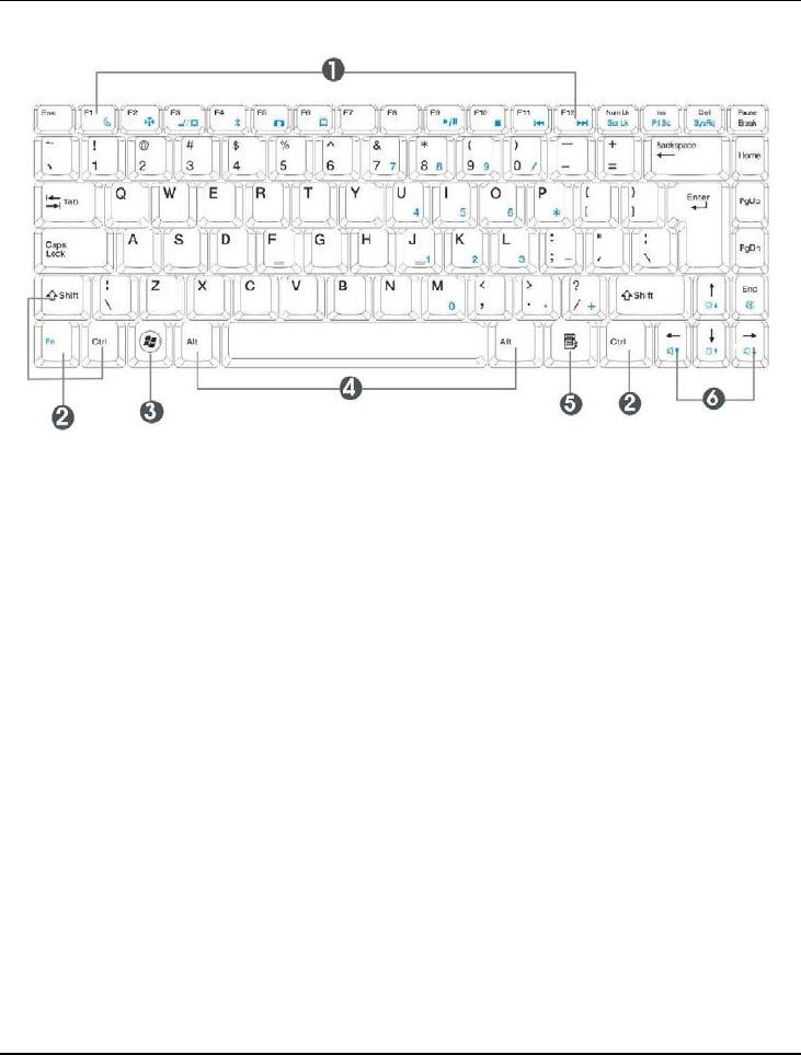
Using Your Notebook 3
81
1. Function Keys 2. Control Keys
3. Windows Start Menu Key 4. Control Keys
5. Windows Shortcut Key 6. Cursor Control Keys
Keyboard
Key features and operations are described below:
• Function Keys
Function keys are application-driven, like F1 through F12 can be found on
the keyboard. These keys work together with the Fn key to activate special
functions. Some keys (printed in blue on keypad) are preprogrammed with
dual functions.
• Control keys — Ctrl, Alt, Fn, and Shift are controls used in conjunction
with other keys to change their functions. To use control keys, press and
hold the control key while pressing another key. For example, "Press Ctrl-
C" means to hold down the Ctrl key and type the letter C. Key
combinations work especially to the application you are running.

Notebook User Guide
82
• Windows keys
Use the following two keys to facilitate your work:
Start Menu key
Displays the Start menu.
Shortcut/Application key
Provides quick access to shortcut menus. This key acts like a right
mouse button.
• Cursor Control keys
Cursor control keys let you position the cursor on the screen where you
want. In the screen, the cursor is a blinking underline, block, or vertical
bar depending on the application. The cursor indicates where the next text
typed is inserted.
• Typewriter keys
Typewriter keys (also called alphanumeric keys) are used to enter text and
characters. Keys with blue print on them behave differently when
combined with control keys.
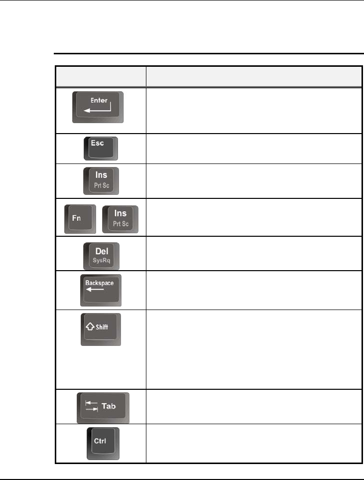
Using Your Notebook 3
83
BASIC KEYBOARD FUNCTIONS
Keypad Function Description
<Enter> key. Execute a command. Within many
text editing application programs, the <Enter> key
inserts a hard carriage return, just like what ordinary
typewriter does.
<Esc> key. Press this key to cancel or escape from
a command or function.
<Ins> key. Known as the Insert key. Press this key
to toggle the keyboard data entry from insert to type
over mode.
+
<Fn> + <PrtScr> key. Known as the Print Screen
key. Press this key to map the whole screen to share
memory for your specific usage.
<Del> key. Known as the Delete key. Press this key
to delete the character to the right of the cursor, or
delete marked texts or items.
<Backspace> key. Press this key to delete the
character to the left of the cursor.
<Shift> key. Press this key in combination with
alphabet letters to produce uppercase letters in
typing. Use this key in combination with those two-
character keys (found on the second row of the
keyboard) to produce the upper marked keys. Also
used in most application program in combination
with other keys to execute a certain command.
<Tab> key. Press this key to move the cursor to the
next tab stop on the right. This key works much the
same as in ordinary typewriter.
<Ctrl> key. Known as the Control key. Used in
most application program in combination with other
keys to execute a certain command.
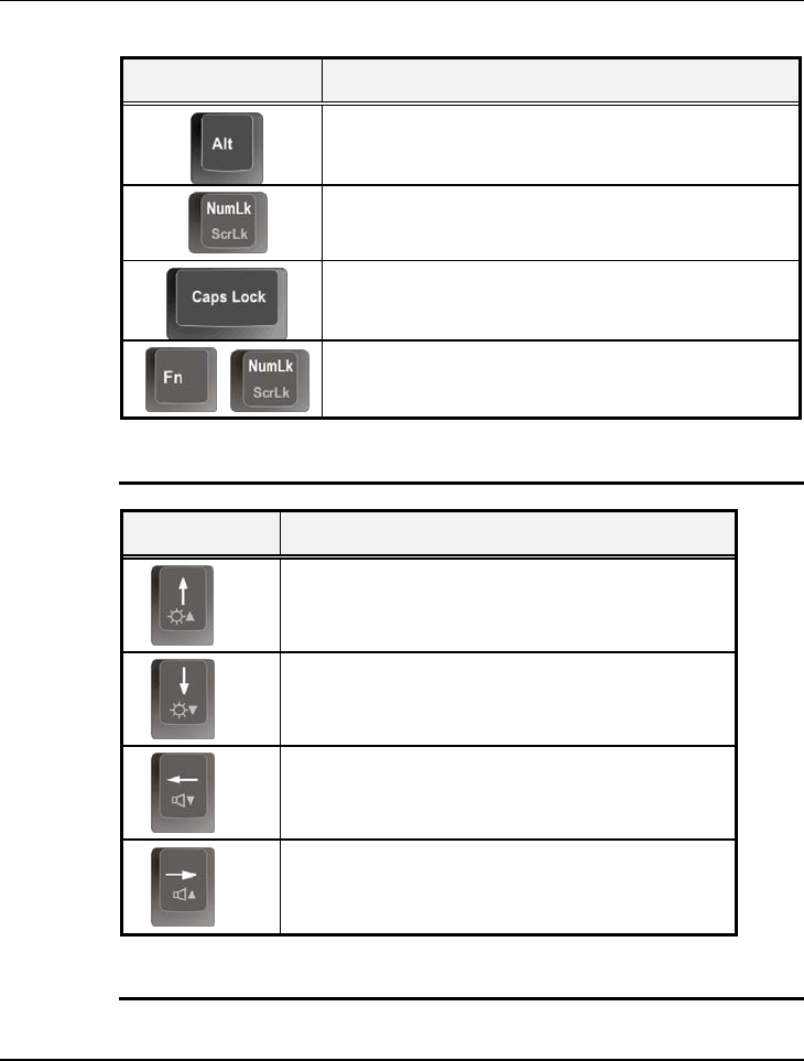
Notebook User Guide
84
Keypad Function Description
<Alt> key. Known as the Alternate key. Used in
most application program in combination with other
keys to execute a certain command.
<Num Lock> key. Activates the embedded 15-key
numeric keypad. The keys are color coded blue.
<Caps Lock> key. Used in most application
program to always activate uppercase alphabet
characters.
+
<Fn> + <Scroll Lock> key. Used in most
application program to scroll the screen without
having to move the cursor.
CURSOR CONTROL KEYS
Keypad Function Description
Up arrow key. Moves the cursor up one line at a
time.
Down arrow key. Moves the cursor down one
line at a time.
Left arrow key. Moves the cursor to the left one
space at a time.
Right arrow key. Moves the cursor to the right
one space at a time.
SCREEN CONTROL KEYS
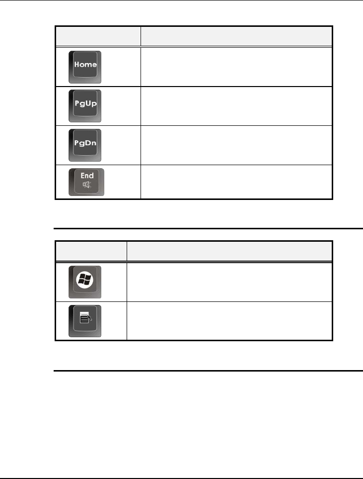
Using Your Notebook 3
85
Keypad Function Description
<Home> key. Moves the cursor to the
beginning of a screen or line.
<PgUp> key. Moves the cursor up one
screen at a time
<PgDn> key. Moves the cursor down one
screen at a time
<End> key. Moves the cursor to the end of a
screen or line.
WINDOWS HOT KEYS
Keypad Function Description
<Start> key. Pulls up the Windows Start menu.
<Right Click> key. Performs a mouse right-click
function for Windows system.
SPECIAL FUNCTION KEYS
The notebook has special system function keys that activate key serving dual
functions. When pressed in conjunction with the <Fn> key, these keys set
specific system parameters and are sometimes referred to as "hot keys".
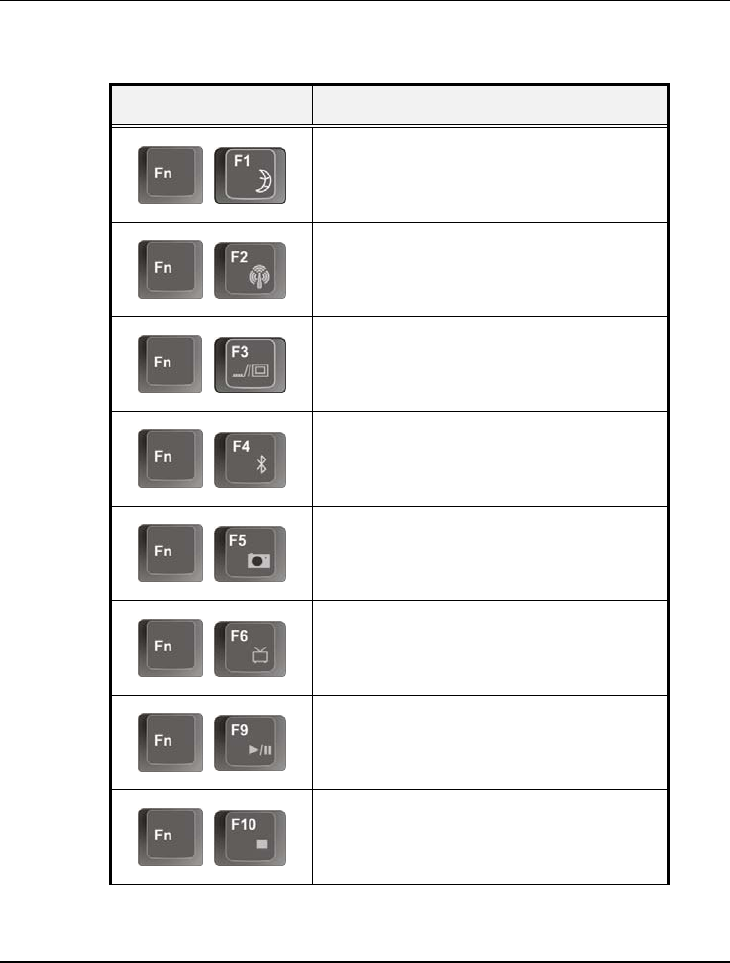
Notebook User Guide
86
Keypad Function Description
+
Switches the system into Suspend mode.
+
To enable or disable the wireless LAN
function.
+
Switches display between LCD, CRT, or
LCD and CRT simultaneously.
+
To enable or disable the Bluetooth
function.
+
To enable or disable the Webcam
function.
+
To enable or disable the TV tuner.
+
To play or pause the music.
+
To stop the music or DVD/VCD playing.
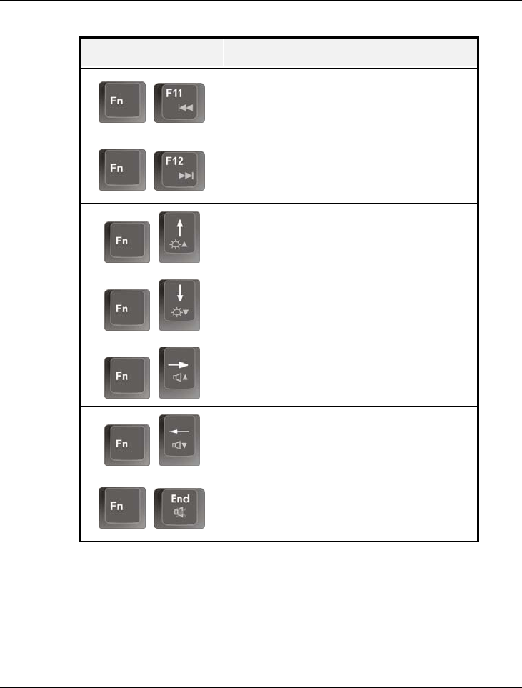
Using Your Notebook 3
87
Keypad Function Description
+
To revert the previous music or previous
DVD (VCD) section.
+
To play the next music or next DVD
(VCD) section.
+
Increases the brightness of LCD display
incrementally.
+
Decreases the brightness of LCD display
incrementally.
+
Increases the audio volume of the
notebook incrementally.
+
Decreases the audio volume of the
notebook incrementally.
+
To shut down or resume the built-in
system speaker volume.
3.3 Using the Touchpad Pointing Device
Your computer comes with a built-in touchpad pointing device that is found
on the center of the palm-rest surface.
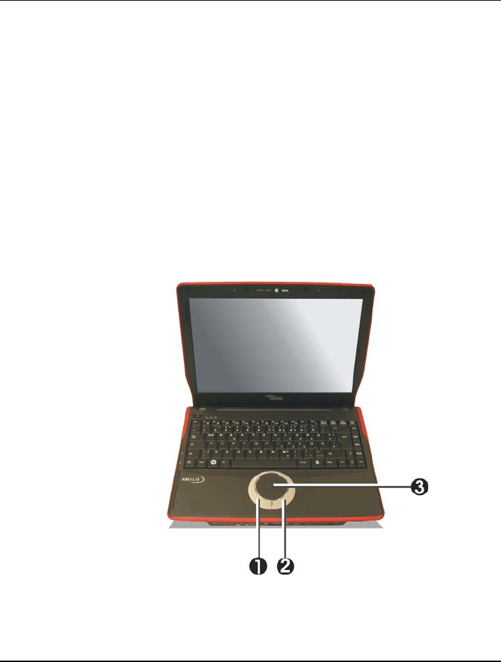
Notebook User Guide
88
The touchpad offers a number of options that let you customize how it
functions. To access these options, locate the Control Panel and double click
on the Mouse icon. The options let you control the size and color of the
cursor, cursor speed, the accepted double-click speed, and selection button
orientation.
The touchpad works a mouse pointing device replacement that is used under
Windows-based operating system. You can use the standard Microsoft driver
that is compatible with the touchpad device and is normally used under
Windows-based operating system. However, if you want to utilize the added
features of the touchpad, you may want to try installing its own device driver
that comes with added utilities for enhancing the function of the device.
1. Left Selection Button 2. Right Selection Button
3. Touchpad

Using Your Notebook 3
89
Touchpad Features
Here how to use the touchpad pointing device:
1. The rectangular surface acts like a miniature duplicate of your display
screen. To move the mouse cursor, place the finger lightly on the sensor
pad and move in the desired direction. If you reach the end of the pad, lift
your finger and place it back down on the other side of the pad.
2. To select an item, click on the item by pressing the left button control or
by simply tapping on the surface once. A light, quick tap always works
best. To execute an item, click the left button twice or do a quick double
tap on the surface.
3. To simulate holding the mouse button down (dragging an icon or
selection), use the tap-and-drag gesture. This feels much like a double-
click, except that the finger remains on the pad after the second tap: Tap,
lift, tap, hold and move. The simulated button remains held as long as the
finger remains on the pad.
4. When you press both the Left and Right click button at the same time, the
auto Scroll function will be activated.
Avoid spilling any liquid on the touchpad surface and always keep the
touchpad surface and pointing finger dry from sweat built-up. Also do not
expose touchpad to any magnetic source object.
3.4 Configuring Your Screen Display
The VGA display function of your notebook is based on a high performance
AGP local bus controller and is fully VGA compatible. This controller offers a
large set of extended functions and higher resolutions especially useful when

Notebook User Guide
90
you are connecting an external high-resolution and high-frequency CRT or
LCD.
Please Refer to Section 5 "Installing the Notebook Device Drivers" of Chapter
2 in this manual for the procedures on how to install the VGA device driver
under Windows. After installing the VGA driver, you would then configure the
display resolution or screen size to match your LCD display panel. This
notebook computer model provides Wide screen 15.4” 1280x800 (Wide XGA)
resolution panels. You would also probably want to set the amount of color
output to display sharper images and photos.
POSSIBLE DISPLAY CONFIGURATIONS
The table below shows you the possible display resolution you can set when
using either the LCD display or the external monitor (CRT):
Display Possible Resolution Maximum Colors
Widescreen
13.3” 1280x800
WXGA LCD
800 x 600
1024 x 768
1280 x 768
1280 x 800
16 million colors
16 million colors
16 million colors
16 million colors
CRT 800 x 600
1024 x 768
1152 x 768
1280 x 1024
16 million colors
16 million colors
16 million colors
16 million colors
65,536 or 64K colors is also equivalent to 16-bit high color while 16 million or
16M colors is equivalent to 32-bit true color.
You can use the <Fn> + <F3> hot-key to switch the display between LCD
only, CRT only, or both LCD and CRT display.

Using Your Notebook 3
91
CHANGING THE DISPLAY PROPERTIES UNDER WINDOWS
To change the display properties of your screen under Windows system, just
right-click on the desktop area and select Properties or go to the Control Panel
and click on the Display icon. The Display Properties dialog box will appear on
your screen. Click on the Settings tab to set your desired configuration. Make
sure to follow the configuration table above.
If you cannot configure the display properties, change the display driver
first as mentioned on Section 5 "Installing the Notebook Device Drivers" of
Chapter 2 in this manual. Consult your dealer for the latest Windows VGA
driver.
3.5 Knowing the Power Saving Features
One of the great features in your notebook computer aside from its superior
performance is the ability to save energy power. Your computer is designed to
incorporate intelligent and advanced power management functions that turn
off power of most components when system is idle or not in use. This feature
not only gives you longer battery hours but cooler systems and components as
well. For more information on how to control the power management features
of your computer, refer to Power Options function in Control Panel of
Windows.
The definitions of Standby Mode, Hibernation Mode, and Shutdown are
depicted as follows:
Standby Mode
Standby Mode is mainly for power saving. When the Standby Mode is
activated, your display and hard drive are shut down and all open applications

Notebook User Guide
92
and documents are stored in RAM (Random Access Memory). This allows
your notebook to wake up quickly, but a low level of power is required to
maintain this suspended state. How quickly your system powers down into
Standby mode is up to you by setting proper times in Power Options of
Control Panel in Window. While the notebook is in Standby mode, the LED
of power indicator flashes. To resume your working again, you can press the
power button to return your work to the screen where you left off.
Hibernation Mode
In Hibernation mode, all system devices are powered down and the contents
of RAM are stored on your hard drive. Hibernate mode uses less power than
Standby mode, but takes a bit longer time to resume. When your notebook
goes into hibernation, Windows saves your entire desktop state before
powering down your computer. You don’t need to save and close each
document before you put your notebook into hibernation. When you press
power button again, system will bring your notebook out of hibernation. You'll
find your applications and documents open on your desktop exactly as you left
them.
Hibernation is enabled by default. To verify that Hibernation is enabledd,
Click
Start
, point to
Settings
, and then click
Control Panel.
Choose
Power Options
icon, then click on the
Hibernate tab
. IF the chock box
of Enable Hibernate is selected, the Hibernation mode is enabled.
Shutdown
All power has been turned off from the notebook. This means that no power
including external AC power source and battery power source will be consume
by the notebook.

Using Your Notebook 3
93
3.6 Working with the Built-in HDD
Your notebook computer is equipped with a built-in large capacity 2.5 inch
IDE hard disk drive where you store or install your computer operating system
and all application software programs. You need to format the hard disk
before using. The internal hard disk is normally assigned as Drive C after
formatting. Sometimes divided into two partitions, adding a Drive D. Since
your computer supports different hard disk capacities (up to 80 GB), you also
need to setup the disk type first on your computer’s BIOS SETUP program
before formatting the disk drive. Your computer supports Auto-detect hard
disk type, so you do not need to set it manually. Your dealer should already
have done all of this for you. You can refer to Chapter 6 on how to run the
BIOS SETUP program.
You can increase the system’s storage capacity by replacing the standard hard
disk drive with a drive of greater storage capacity.
If you wish to replace your hard disk, contact your local dealer for more
information about this dealer-installable device.
Always turn off your computer first before removing the hard disk drive.
Failure to do so will damage the computer and the hard disk. Avoid jarring
or moving the computer while the hard disk is still being accessed.
3.7 How to Access the Optical Drive
Your system ships with an optical disk drive installed on the right side of your
computer. You would normally use the drive for installing operating system
and software application programs.
To insert and remove a disc on the drive:
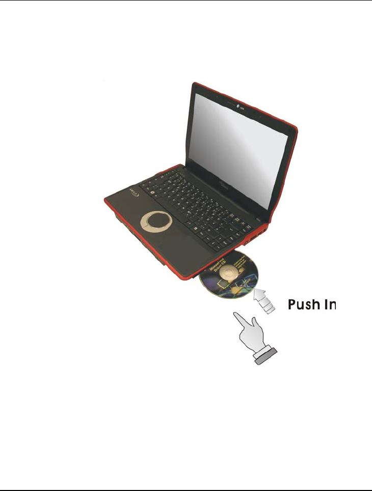
Notebook User Guide
94
1. Make sure the computer is turned on. Insert the Optical disk into the
drive slot with the label side facing up. The optical disk will be
automatically slide in the optical drive.
2. To remove the disc, press the eject button found on the left bottom side
of the optical drive.
3. The optical disk will pop-out slightly.

Using Your Notebook 3
95
How to care the Optical Disks (CDs, DVDs, etc.)
When you handle CDs, pay attention to the following guidelines:
• Always pick up the disk by its edges.
• Avoid scratching or soiling either side of the disk.
• Do not write with the hard ball-point pen or apply labels on either side of
the disk.
• Keep the disk away from direct sunlight or high temperatures.
• Clean fingerprints or dust from the disk by wiping it with a soft cloth.
The above points also apply to other optical storage media.
The Combo drive is a Class 1 Laser Product.
3.8 ExpressCard
WHAT IS EXPRESSCARD ?
The ExpressCard is a newly developed PC Card interface, its connector has
just 26 pins and the interface has a potential transfer rate of up to 500 MB/sec
(or 250 MB/sec in each direction) using a single-lane PCI Express link. Its
form factor is up to 40 percent smaller than a PC Card, which allows
ExpressCard modules to be included in smaller host systems. Designed for
both desktop and mobile use, ExpressCard use either USB 2.0 or a single lane
PCI Express technology.
The ExpressCard standard was developed by PCMCIA member companies
including technology leaders, system manufacturers, card manufacturers, from
all other parts of the PC Card industry.
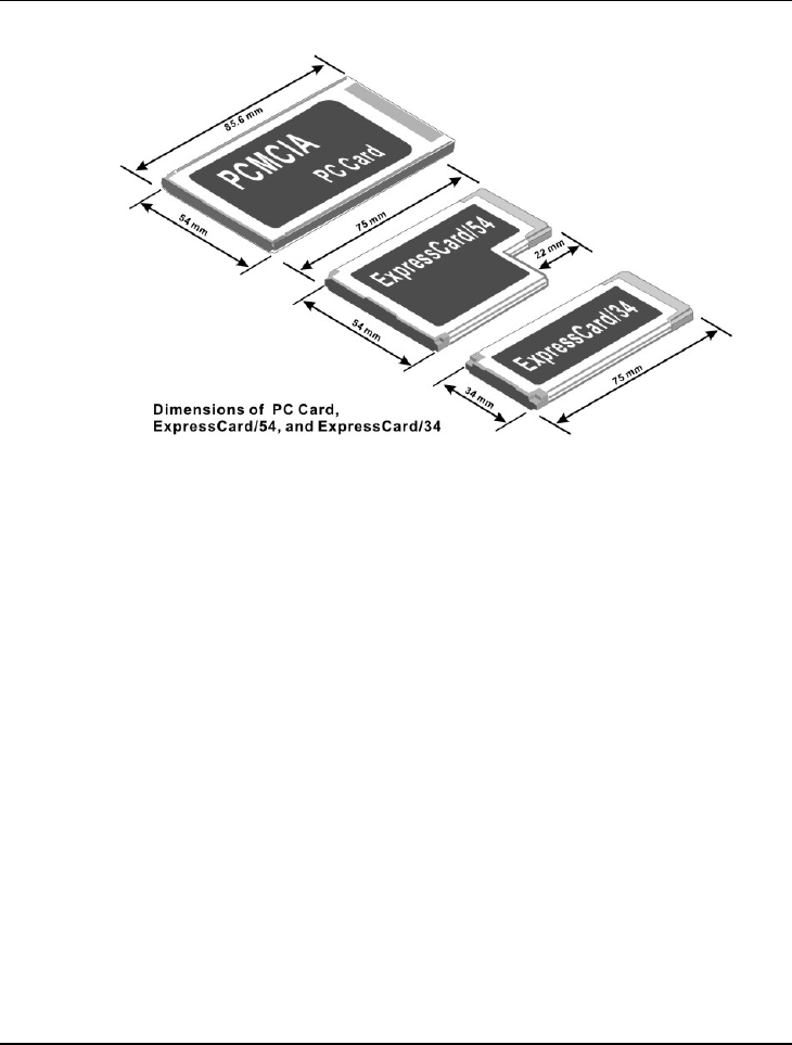
Notebook User Guide
96
Dimensions of ExpressCard
Current CardBus PC cards are 54 millimeters wide. ExpressCard can divided
into two categories, based on width. Most designs will use the ExpressCard 34
design, which sets the width at 34 millimeters. For some applications, the wider
ExpressCard 54 standard will be used to produce cards that can handle the
higher thermal requirements of those applications.
All ExpressCard modules are 5mm thick but the standard also allows for card
developers to build longer 'extended' modules.
Native Bus Connection
The ExpressCard standard supports both the USB 2.0 and PCI Express
interfaces. Card manufacturers are able to choose whichever bus is appropriate
to their application; the performance of PCI Express, or from the wide range
of solutions supported by USB. All host PC ExpressCard slots will support
cards using either interface. The host platform no longer needs to incorporate
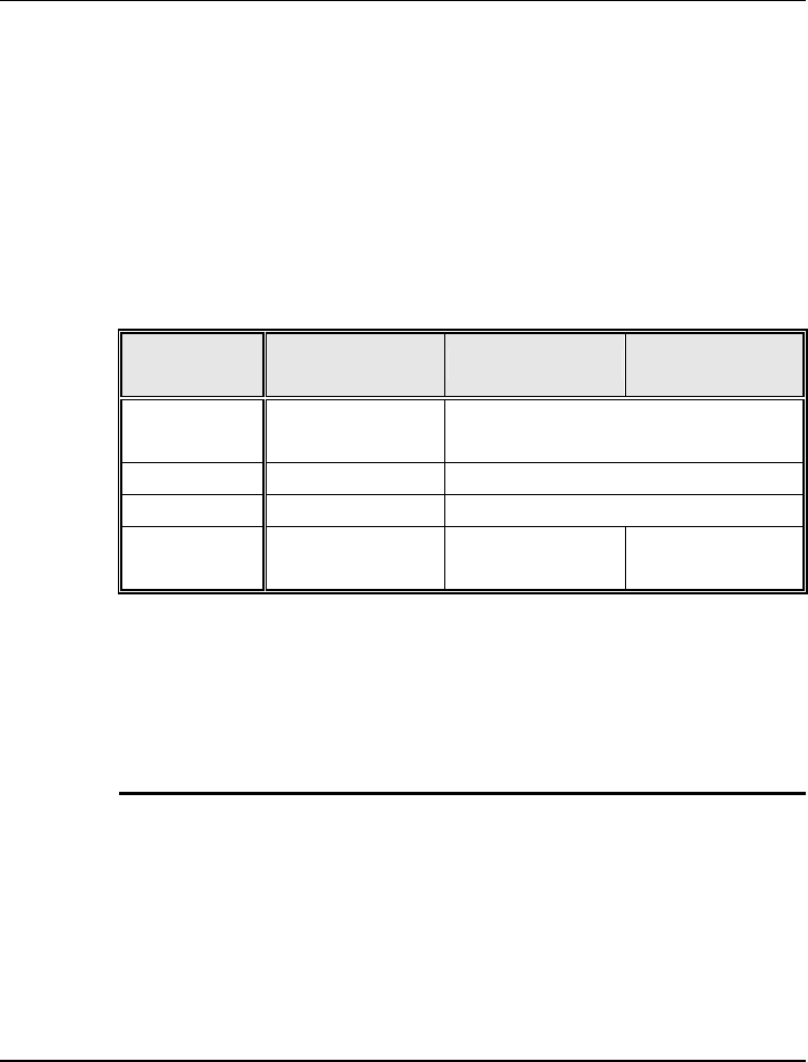
Using Your Notebook 3
97
a bridge chip between the chipset and the socket. PCI Express and USB 2.0
are fully hot-pluggable.
To support the broadest range of applications there are two sizes of module.
Both are smaller that today's CardBus card. The smallest card, the
ExpressCard/34 module, is almost half the size of a CardBus card. This size is
suited to a very broad range of applications covering communications, media,
and general purpose.
PC Card
(CardBus, Type II) ExpressCard/54 ExpressCard/34
Data Transfer
rate 132 Mbps 500Mbps (or 250Mbps in each direction)
Connector pins 68 26
Port Type Parallel Serial
Dimensions
(HxWxD)
54mmx86mmx5m
m
54mmx75mmx5m
m
34mmx75mmx5m
m
A big part of "just working" will be the existing software support. Both
Windows XP and Windows Vista already support the ExpressCard
specification.
INSERTING AND REMOVING A EXPRESSCARD
Your computer includes hot swapping capability, that allows you to exchange
cards while the computer is turn on and start using it immediately.
Inserting ExpressCard
To insert a ExpressCard into the ExpressCard slot:
1. Locate the ExpressCard slot cover on the front side of the computer.

Notebook User Guide
98
2. Insert the side of ExpressCard with the 26-pin socket into the
ExpressCard slot. The face label of the card should also be facing up.
3. When the full length of the card is almost inside the slot, push firmly but
slowly, to ensure full connection with the computer. The ExpressCard will
be automatically detected and once the needed driver is installed, it will
generate a beep sound to indicate that the card is detected.
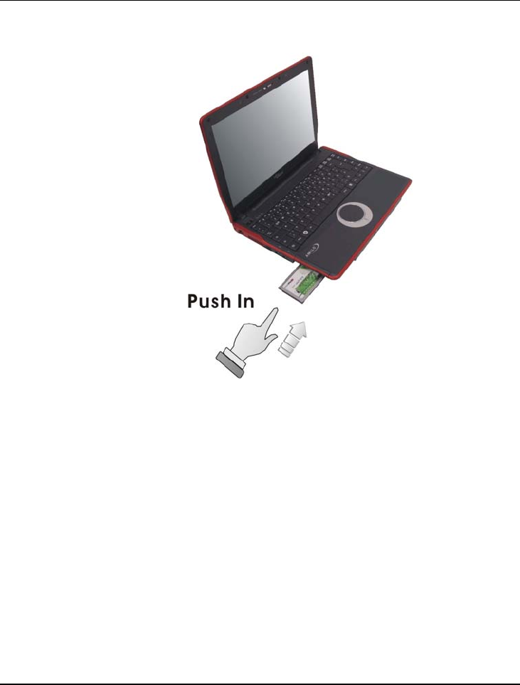
Using Your Notebook 3
99
Removing ExpressCard
To remove a ExpressCard from the ExpressCard slot, you should first disable
the ExpressCard card setting in the system as described followings:
1. Double click the ExpressCard icon on the right bottom side of the task
bar.
2. Select the socket from the list that you want to remove, and click Stop
button. The system then disables the function of ExpressCard card.
3. Then you can remove the inserted ExpressCard, push the ExpressCard to
the bottom to release the ExpressCard.
4. When the ExpressCard has moved out a space out of the slot, hold the
edges of the card and slowly slide it out.
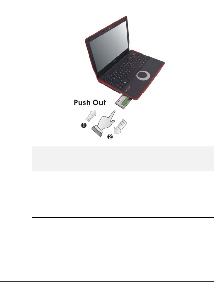
Notebook User Guide
100
The power consumption of ExpressCard/54 is about 2.1W, while the
consumption of ExpressCard/34 is about 1.3W. To save energy, press the
button to disconnect the card when it is not in use.
3.9 Using Flash Memory Cards
WHAT IS FLASH MEMORY CARD?
Flash Memory is a memory storage media. It is used by most digital camera,
moreover, it can replace the traditional floppy disk. Flash memory card is built
with different form factor and brand name. Their size is smaller than PCMCIA
card. This computer supports most of the flash memory card, including SD,
MMC, MS (Memory Stick), and MS_Pro card.

Using Your Notebook 3
101
The 4 in 1 card slot is used by the following cards as SD, MS (Memory Stick ),
MMC, and MS_Pro.
For a single moment, only one card can be inserted into the 4 in 1 card slot
Inserting Flash Memory Card
To insert a flash memory card into the slot is similar to ExpressCard. You only
need to pay more attention whenever insert the flash memory card into the slot
with the correct side.
For MMC and SD card, you should position the copper connector at the
bottom side. For Memory Stick card, you should position the copper
connector at the topside. All of these cards should be located at the center of
the slots in inserting.
Slot Card type Copper connector
4 in 1 SD (Secure Digital)
MMC (MultiMedia Card)
MS (Memory Stick)
MS_Pro
Bottom side
Bottom
Top side
Top side
Only one correct side can be accepted for the 4 in 1 card slots. If you cannot
insert the card into the 4 in 1 slot or you had inserted the card but it is not
recognized by the computer, please remove the card and turn the card upside
down and insert it again. To prevent the damage made both on card and the
slot, never forced an entry into the slot with incorrect side.
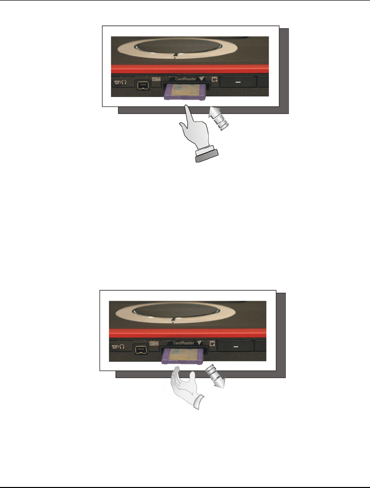
Notebook User Guide
102
Removing Flash Memory Card
It is similar to ExpressCard for removing a flash memory card from the slot.
You should first disable the card setting in the system as described in the
former section.
To remove the flash memory card, you should only pull out the card by finger,
there is no release button for flash memory slot.
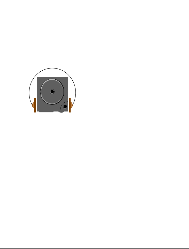
Fun with Multimedia 4
103
4 Fun with Windows Vista
Experience
This notebook integrated in a highly
compact platform is designed for
digital entertainment. With Windows
Vista, it offers a breakthrough user
experience and is designed to help you
feel confident in your ability to view,
find, and organize information and to
control your computing experience. It
simplifies our digital life in taking
charge of media, share moves, TV,
photos, and music with your friends
and family.

Notebook User Guide
104
4.1 What is Windows Vista?
Windows Vista is an operating system that enables you to enjoy the best in
entertainment on your notebook.
The visual sophistication of Windows Vista helps streamline your computing
experience by refining common window elements so you can better focus on
the content on the screen rather than on how to access it.
With Windows Vista, you can store, share and enjoy all of your photos, all of
your music, all of your home video and even recorded TV. It’s all contained in
one control system. That is as easy to use with a great new user-friendly
interface.
4.2 Get Ready for Windows Vista
Windows Vista is designed to help make you more productive as you work
with your PC throughout the day with new features.
Starting the Windows Vista
When you start using Windows Vista, you will recognize familiar elements
such as the Start menu, which is now faster, more streamlined, and more
helpful than in previous versions of Windows. More than that, the new start
menu makes it very easy for you to navigate across all of the installed
applications on your PC. Eliminating the slow performing, cascading "All
Programs" view, the new start menu can help you get something started more
quickly than ever.
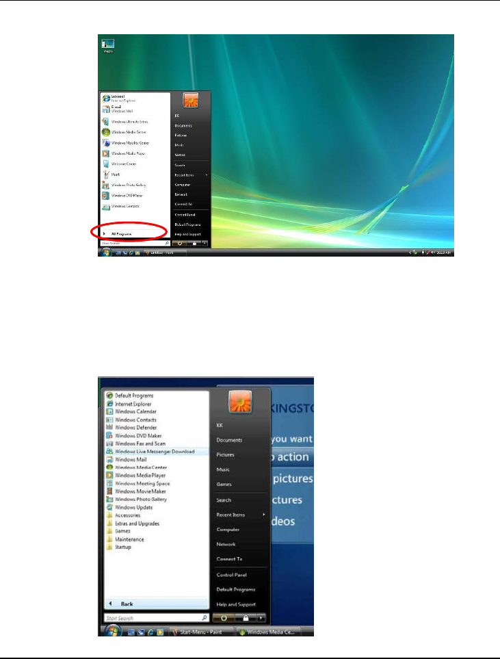
Fun with Multimedia 4
105
About the entertainment
To recall all default multimedia applications, click on “All Programs” located
on the left corner on the desktop, the “All Programs” will be changed to
“Back” as shown in the following figure.
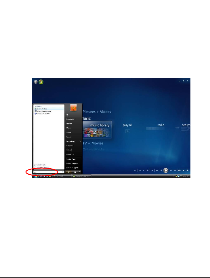
Notebook User Guide
106
It now becomes more easy to execute various application with just click on it.
Instant Search
The Start menu features integrated desktop search through a new feature
called Instant Search which can help you find and launch almost anything on
your PC. Just type in a word, a name, or a phrase, and Instant Search can find
the right file for you.
Use Instant Search to quickly find the information you need.
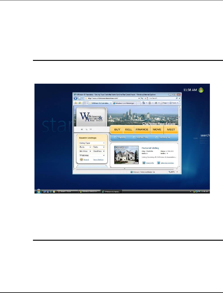
Fun with Multimedia 4
107
4.3 Enjoy Your Multimedia Application
INTERNET EXPLORER
Windows Vista enhances the Internet Explorer experience in finding and
displaying information, and Web sites on the Internet.
The upcoming release of Internet Explorer 7 not only adds important new
security and privacy features, but makes everyday tasks easier through features
such as tabbed browsing, inline search, and shrink-to-fit printing
WINDOWS CALENDAR
Windows Calendar helps you in management appointments and tasks by
creating personal calendar, publishing them, and subscribe to other users
calendars.
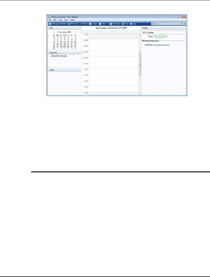
Notebook User Guide
108
Windows Calendar is a flexible, easy-to-use calendar built directly into the
Windows Vista operating system. It lets you plan and manage all of your
activities and coordinate your schedule with others. It also lets you create a
personal task list and receive automatic notifications and reminders about
specific tasks and upcoming appointments.
Windows Calendar has a broad range of features to help you manage your
personal schedule
WINDOWS CONTACTS
Windows Contacts can store e-mail addresses and other information about
people and organizations.
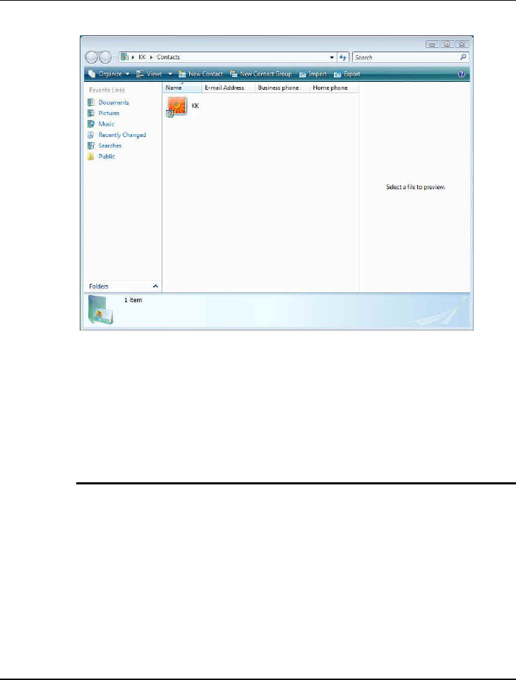
Fun with Multimedia 4
109
Microsoft Windows Vista provides a new mechanism and user interface for
storing and retrieving information about people (contacts) who are important
to the users of Microsoft Outlook and Windows Mail (formerly Outlook
Express).
WINDOWS DEFENDER
Windows Defender is enable to protect the computer from spyware and other
potentially unwanted software.
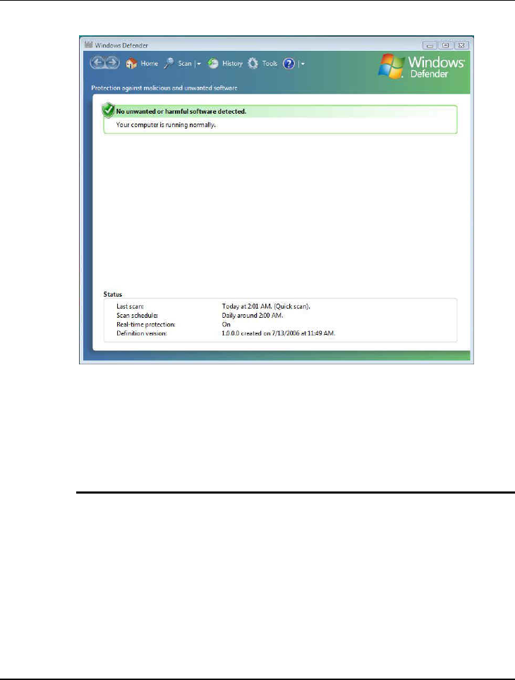
Notebook User Guide
110
Windows Defender helps protect computers against pop-ups, slow
performance, and security threats caused by spyware and other unwanted
software. Applications can check and change its status.
WINDOWS DVD MAKER
Windows DVD maker helps you burn pictures and video to DVD..
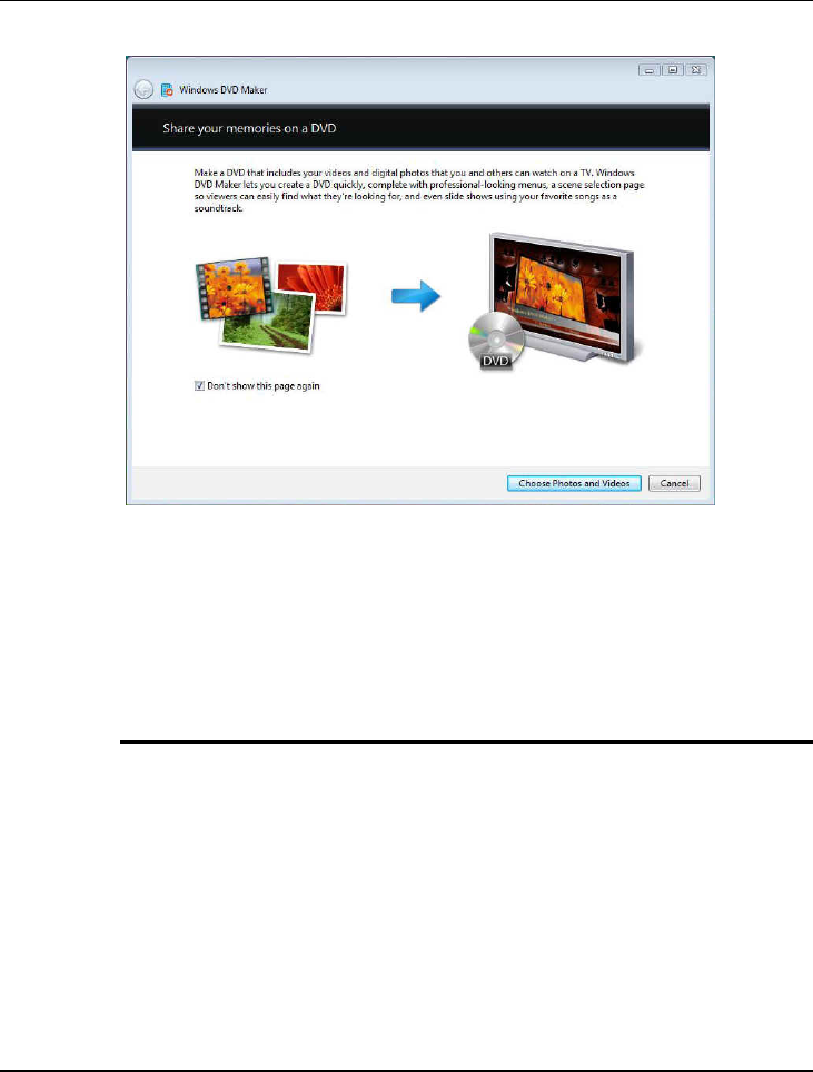
Fun with Multimedia 4
111
Windows DVD maker lets you create a DVD quickly, complete with
professional-looking menus, a scene selection page so viewers can easily find
what they are looking for, and even slide shows using your favorite songs as a
soundtrack.
WINDOWS FAX AND SCAN
Windows Fax and Scan help you send and receive faxes or scan pictures and
documents.
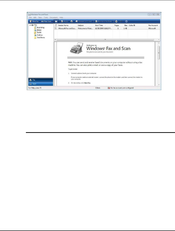
Notebook User Guide
112
Faxing and scanning functions come together in Windows Vista through
Windows Fax and Scan. Sending and receiving faxes through your PC is now
as simple as performing the same tasks on a fax machine, especially for digital
document
WINDOWS LIVE MESSENGER DOWNLOAD
Windows Live Messenger Download can connect and share message instantly
on the world’s favorite IM service..

Fun with Multimedia 4
113
Windows Live Messenger is the next-generation MSN Messenger. It has
everything you already love about Messenger, and much more.
WINDOWS MAIL
Windows Mail can send and receive e-mail and newsgroup messages.
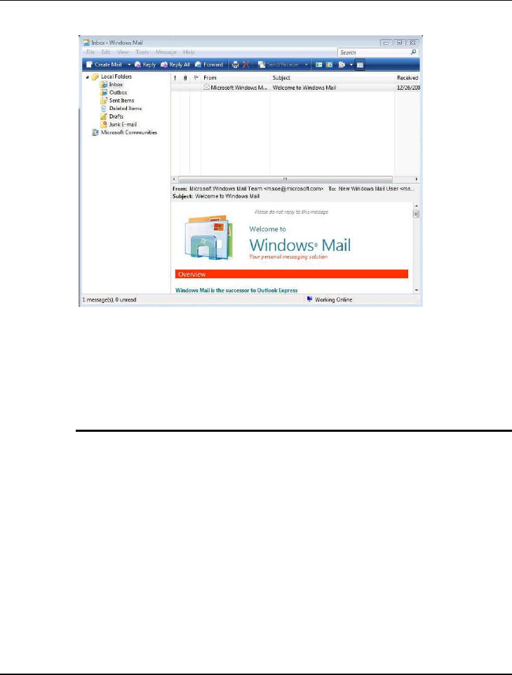
Notebook User Guide
114
Windows Mail is designed to help you prevent emerged some annoyances and
risks that have grown over the years, that enables your e-mail experience is as
productive and fun as possible. Windows Mail includes features that help you
reduce the risks, while enjoying the many benefits, of e-mail
WINDOWS MEDIA CENTER
Windows Media Center lets you opens your home entertainment option for
digital and on-demand media, including TV, Movies, music and pictures.
It is enable to make you enjoy all your favorite digital entertainment—
including live and recorded TV, movies, music, and pictures—in one place
with the easy-to-use Windows Media Center menu system and remote control.
Windows Media Center in Windows Vista includes enhancements for
expanded support of digital and high-definition cable TV, an improved menu
system, and the ability to create a consumer-electronics-quality living-room
experience, as well as new options for multi-room access to your
entertainment through Media Center Extenders.
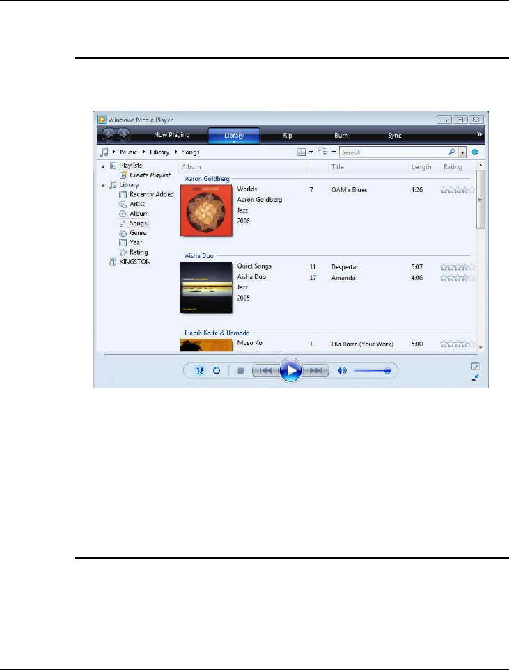
Fun with Multimedia 4
115
WINDOWS MEDIA PLAYER
Windows Media Player can play digital media including music, video, CDs and
DVDs.
Windows Media Player gives you an easier way to enjoy and manage your
digital music, video, and pictures on your PC. See things the way you want to
see them, by CD cover art or in lists. Connect to networked media devices
around your home or seamlessly sync up with your portable digital media
player to enjoy all your entertainment wherever you are. Sporting an improved
look and feel, Windows Media Player delivers a high-quality audio and visual
experience both on the computer and around your home
WINDOWS MEETING SPACE
Windows Meeting Space lets you share files, a program, or your laptop
anytime and anywhere.
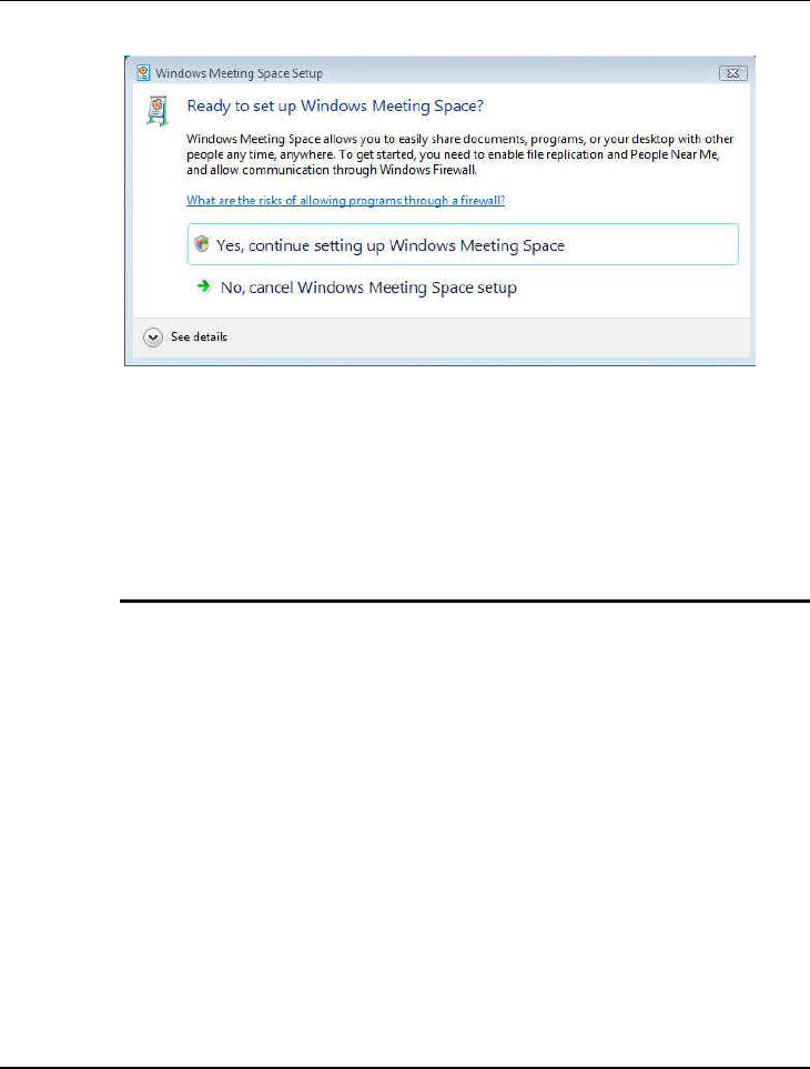
Notebook User Guide
116
Windows Meeting Space gives you the ability to share documents, programs,
or your desktop with other people. Some advantages are: you can share your
desktop or any program with other meeting participants; you and other
meeting participants can distribute and co-edit documents; you can pass notes
to other participants; you can connect to a network projector to give a
presentation.
WINDOWS MOVIE MAKER
Windows Movie Maker helps you make your own movie using videos, digital
pictures and movies.
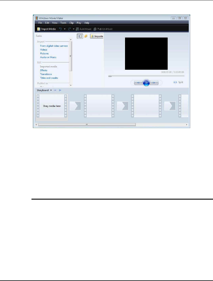
Fun with Multimedia 4
117
With Windows Movie Maker, you can quickly and easily import, edit, and
organize all of your digital home videos. New tools, such as new effects and
transitions, and improved graphics performance help you manage and edit
your home videos. You can include photos along with video when you create a
movie, and even add narration and soundtracks. Once your movies are just the
way you want them, you can easily burn them to DVD or share them with
others through the Internet
WINDOWS PHOTO GALLERY
Windows Photo Gallery lets you view , edit, organize, and share your photos
and videos.
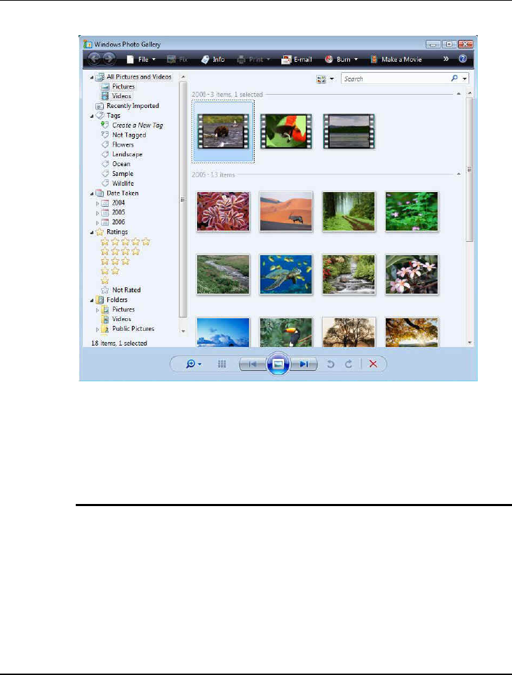
Notebook User Guide
118
Windows Photo Gallery in Windows Vista gives you the tools you need to
easily organize, find, and view your photos and videos. You can edit, print, and
share your photos from within Windows Photo Gallery, as well as transfer
photos from your camera to your computer with a simple import process
WINDOWS UPDATE
Windows Update delivers software updates and drivers, and provide automatic
updating options.
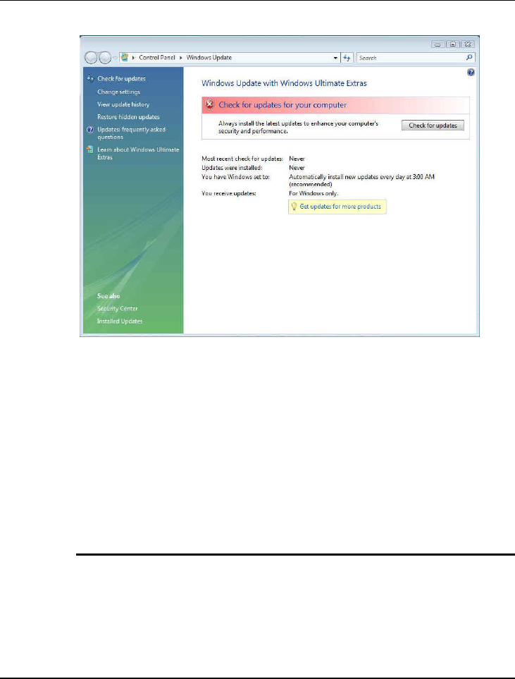
Fun with Multimedia 4
119
Windows Update keeps your computer up to date and more secure by
automatically providing software updates to Microsoft Windows Vista.
Updates can include upgrades to Windows Vista features, updates that
improve reliability and performance, and updates that provide new security
protections against malware and other potentially unwanted software.
Windows Update makes updating easy and minimizes disruption to your work.
It's easy to start updating—when you set up Windows Vista, you can set
options that enable Windows Update to automatically download and install
updates for you—so you can "set it and forget it
WINDOWS SIDEBAR AND GADGETS
As you use your computer to access more information, perform more tasks,
and interact with more software applications, you increasingly face information
overload. You open a web browser just to check the weather, open an
application to view your calendar, and open a calculator program to simply add
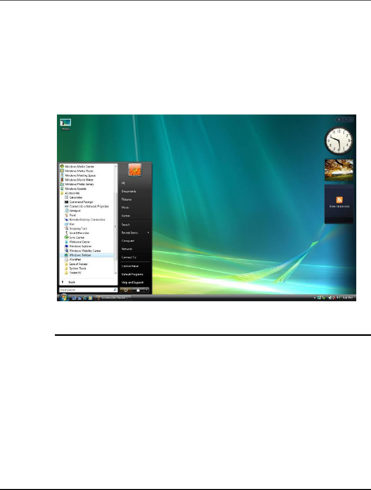
Notebook User Guide
120
numbers. You need simple, specialized, and lightweight mini-applications that
put information and tasks at your fingertips—no matter what you're doing.
Windows Sidebar boosts your personal productivity by providing instant
access to gadgets—a wide variety of engaging, easy-to-use, and customizable
mini-applications that offer information at a glance and provide easy access to
frequently used tools
GAMING
If you are a parent, you now have a rich set of controls to ensure your children
are only playing games that you consider appropriate. You can allow or restrict
your children's access to games according to game title, rating, category, or
content. Windows Vista supports six international rating standards and makes
it easy for parents to manage and monitor their children's gaming experience
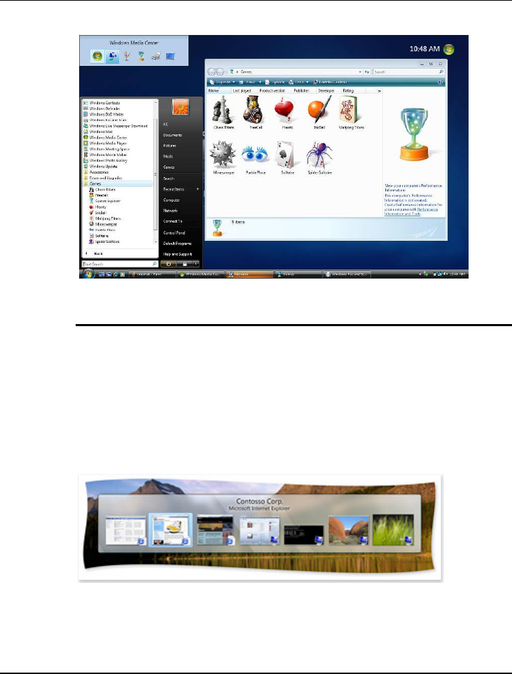
Fun with Multimedia 4
121
WINDOWS FLIP AND WINDOWS FLIP 3D
Windows Vista provides two entirely new features to manage windows:
Windows Flip and Windows Flip 3D. Flip allows you to flip through open
windows (by using Alt+Tab), providing a live thumbnail of each window,
rather than just a generic icon and file name. Live thumbnails make it easier to
quickly identify the window you want, particularly when multiple windows of
the same kind are open. With Flip 3D, you can use the scroll wheel on your
mouse to flip through open windows in a stack, and quickly locate and select
the one you want to work with.
Use Flip to view and navigate more easily through open windows.

Notebook User Guide
122
You can visit and browse each domain to experience the information and
assistance that Windows Vista offers.
For more information, please refer to Microsoft’s website:
http://www.microsoft.com/windowsvista/features/default.mspx
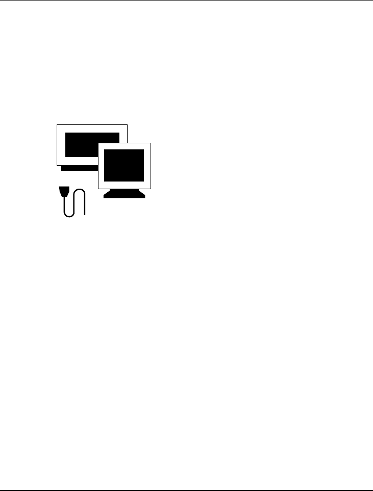
Connecting to Peripherals 5
123
5 Connecting to Peripherals
This chapter describes how you attach peripheral
devices to your notebook. You can attach a printer
or mouse; connect an external monitor and
keyboard, or any other peripheral device. You will
learn how to use these peripheral devices with the
step-by-step instructions depicted in this chapter.
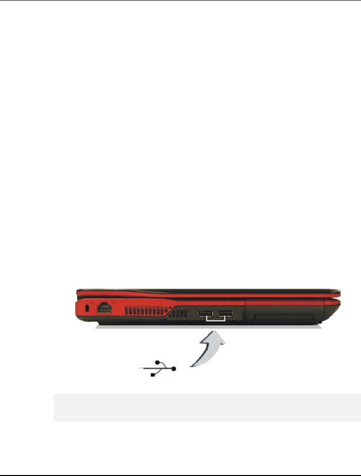
Notebook User Guide
124
5.1 Using the USB Port
USB (Universal Serial Bus) is a hardware interface that enables you to connect
multiple devices (such as printers, mice, keyboards, storage devices, joysticks,
digital cameras, and video conference cameras, etc.) to your notebook
computer, and up to 127 devices can be attached. Besides, USB’s hot swap
capability allows everything to be plugged in and unplugged without turning
the system off.
Microsoft, HP, Compaq, Intel, Agere, NEC and Philip are seven core
members of USB-IF to have worked on USB 2.0 standardization. USB 2.0
offers data transfer rate up to 480Mbps (megabits per second) compared to
USB 1.1 devices, which transfer at speeds of 12Mbps. So, you could know that
USB 2.0 can transfer data between the computer and its peripherals 40 times
faster than USB 1.1. However, USB 2.0 is fully backward compatible, you will
be able to use a USB 1.1 device in a USB 2.0 compliant system.
Depending on your operational requirements, you may need to disable
other ports in order to release system resource for the USB port.

Connecting to Peripherals 5
125
The USB bus distributes 0.5 amps (500 milliamps) of power through each
port. For the purpose of power saving, please disconnect your USB device
while not in use.
5.2 Using the IEEE 1394 Port
IEEE 1394, also known as FireWire, is a high-bandwidth serial bus developed
by Apple and Texas Instruments. IEEE 1394 supports 100, 200, and 400
Mbps (Megabit per second) transfer rates and is widely used for downing video
from digital camcorders to the computer. In addition to its high speed, IEEE
1394 enables isochronous (real-time) data transfer. This makes it ideal for
devices that transfer high-bandwidth of data in real-time, such as video devices.
It supports both Plug-and-Play and hot plugging, and also allows for the
connection of up to 63 devices.
With built-in IEEE 1394 port, this computer enables the peripheral devices in
transmitting digital video data or data backup. The Windows system will
automatically recognize it after installing a suitable driver for it. Please visit
Microsoft's web site for more information about it. Moreover, you should
install the driver of peripheral device to connect with the IEEE 1394 port, for
details please refer to the manual that comes with your peripheral device.
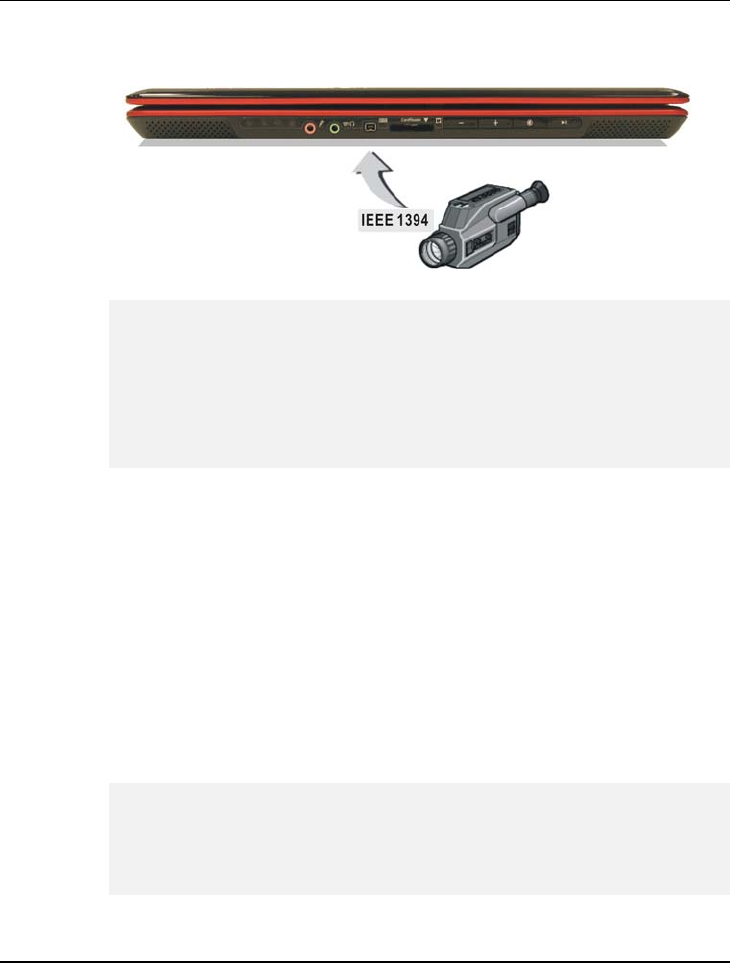
Notebook User Guide
126
Please make sure that the external IEEE 1394 HDD box you purchase on
local electronic store should provide external power adapter. There are
different types of IEEE1394 HDD box and hard disk from different
manufactures, the power consumption has varied range. If the power of the
external IEEE 1394 HDD is supplied from the USB of this notebook, it may
not run properly.
5.3 Using the External Monitor Port
Your computer has a 15-pin Monitor port for supporting any external CRT or
LCD color monitor. You need a display signal cable (usually provided with the
monitor). One end of the cable must have a 15-pin connector for the system.
To connect an external monitor:
1. Turn off your computer and make sure the monitor power switch is
turned off.
The notebook computer must be powered off or suspended while the
monitor is being connected. Although you can connect the external Monitor
without power off the computer and the external monitor, however, it is
harmful to both devices and it shortens the life of these devices.
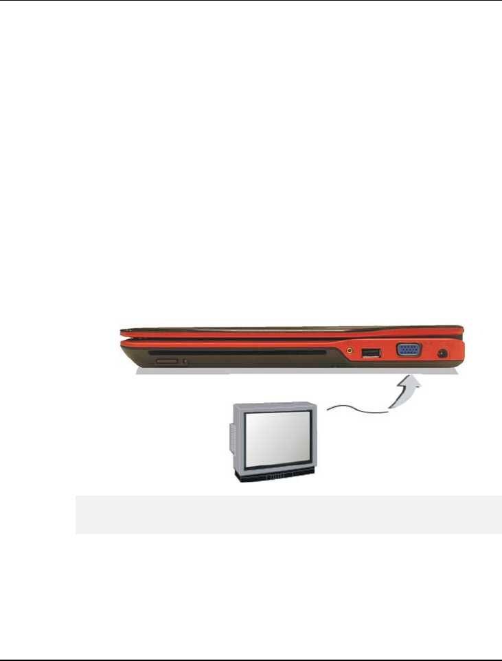
Connecting to Peripherals 5
127
2. Connect the connector cable of the monitor to the VGA port at the back
of your computer. Secure the cable connection with the screws provided.
3. Connect the monitor power cable and plug it into a properly grounded
wall outlet.
4. Turn on the power of the monitor.
5. Turn on your computer. Both the LCD panel and the monitor screen will
show the display. Your computer is set at default to run at simultaneous
display mode.
6. If you only want to show the display on the external monitor or projector
and shut off the LCD display, you can use the <Fn> + <F3> hot-key to
switch display type between LCD and external monitor. Keep pressing the
hot-key until you get the display to external monitor only.
Refer to Chapter 3 regarding the possible External CRT resolutions and
how to change the display properties.

Notebook User Guide
128
5.4 Using the Antenna Port
Your system is equipped with an antenna port and provides an antenna
module for TV watching. .
To access the TV channel:
1. Turn on your system and make sure your notebook is positioned with the
area for easily searching the TV channel.
2. Connect the antenna cable to the right side of the antenna port at your
notebook.
3. Execute the Windows Media Center program for TV setting, TV
watching, recording your favorite TV shows or burning your TV
programs.
For more information, please refer to Microsoft’s website,
http://www.microsoft.com/windowsxp/mediacenter/using/getstarted/de
fault.mspx.
4. Reorient or relocate the receiving antenna if you cannot access the TV
channel successfully.
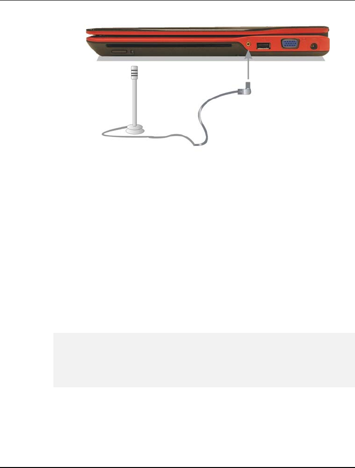
Connecting to Peripherals 5
129
5.5 Using the External Audio System
At the right side of your computer, you will find the built-in audio ports. You
can connect Microphone jacks, earphone or powered speaker.
To connect to a audio jack:
1. Locate the audio port (Microphone, Headphone) that you want to use to
the target device.
2. Plug the jack into the port on the front side of the system.
If you use external speakers and experience the sound distortion or
feedback, please lower the volume. Some factors is caused by too close
locating the microphone and speakers from each other, moving away the
external audio option from the unit may also help.
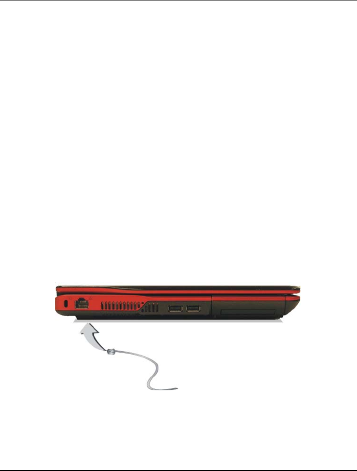
Notebook User Guide
130
5.6 Using the LAN Port
This notebook comes with an internal 10Base-T/100Base-TX LAN module
that connects your computer to other computers/networks through a local
area network (LAN) and supports data transfer rates at 10Mbps and can be up
to 100Mbps. The 10Base-T standard also called Twisted Pair Ethernet is
connected with RJ-45 connectors. The 100Base-TX is based on the older
Ethernet standard. Because it is 10 times faster than Ethernet, it is often
referred to as Fast Ethernet.
The built-in LAN module provides a standard RJ-45 connector.
To connect the twisted-pair cable to your LAN port:
1. Locate the twisted-pair cable in the accessories box in notebook shipping
carton. Each end of the cable has a RJ-45 connector.
2. Connect one end of the cable into the network wall outlet or HUB.
3. Connect the other end of the cable into the computer RJ-45 LAN port.

Connecting to Peripherals 5
131
5.7 Using the Wireless LAN
Wireless LAN is the major breakthrough in computer communication
technology. It lets user connect to the LAN environment without using any
wire to traditional RJ-45 jack. User can enjoy the wireless connection within
the range of Access Point (AP) of LAN.
Access Point (AP) is the wireless transmission and receiving device, it generally
connects to the server of a LAN environment or act as a LAN hub with
wireless connection. Access point can be set in an office environment, airport,
major railway station, etc. that depends on the construction of each country. In
most case, you probably can use it at office, please consult with the network
department of your company for more details.
This computer integrates built-in 802.11 a/b/g/n wireless LAN module. IEEE
802.11b standard supports 11 Mbps wireless connection speed. However,
IEEE 802.11g supports 54Mbps wireless connection speed, and is backward
compatible with the slower 802.11b.
Wireless LAN module is similar to LAN module. You need to install software
driver before using it. Please refer to chapter 2.5 on how to install the driver.
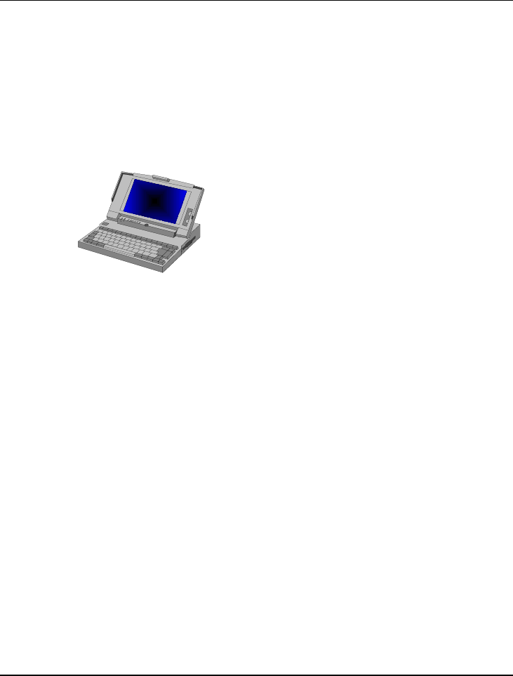
Customizing Your Notebook 6
133
6 Customizing Your Notebook
Your computer uses the Phoenix BIOS Setup
program that allows you to set several system
configuration in changing the way your computer
performs. This includes your system time and date,
disk drive configuration and password setup. This
information is then stored in the CMOS RAM and
will remain permanent unless you change it again.
This chapter discusses on how you will activate the
BIOS Setup program and change the system
configuration to suit your desired operation. You
must be careful to set the configuration properly in
order for your computer to run smoothly. If you are
not sure of any settings, contact your dealer.

Notebook User Guide
134
6.1 Running the BIOS Setup Program
Your computer is likely to have been properly setup and configured by your
dealer prior to delivery. However, you may find it necessary to use the
computer’s BIOS (Basic Input-Output System) Setup program to change
system configuration information, such as the current date and time, or your
hard disk drive type. The Setup program can be accessed when you power on
the system and pressing the <F2> function key.
The settings that you specify within the Setup program are recorded in a
special area memory called the CMOS RAM. This memory is backed up by a
battery so that is will not be erased when you turn off or reset the system.
Whenever you turn on the computer, the system will read the settings stored in
the CMOS RAM and compare them to the equipment check conducted during
the Power On Self Test (POST). If an error occurs, an error message will be
displayed on the screen, and you will then be prompted to run the Setup
Program.
As the POST (Power-On Self Test) executes during the boot up process, the
screen will display the following message:
Press <F2> to Enter SETUP
Press the <F2> key to run the BIOS Setup program. The BIOS Setup
program is organized into five menus which you can select using the <-- and --
> keys. To move from one option to another, you use the up and down arrow
keys while using the <F5> and <F6>, or <+>and <-> keys to change the
settings. On the right hand side of the screen are some brief help descriptions
of each item you want to change.
On the BIOS Setup program, you will find the following parts on the screen:

Customizing Your Notebook 6
135
• Item Specific Help
The right side of the screen. This area describes each parameter and its
available settings.
• Menu Bar
The top line of the screen. Each of the five selections displays its own
screen.
• Parameters
The left side of the screen. This area lists the parameters and their current
settings.
• Key Status Bar
The bottom part of the screen. These lines display the keys available to
move the cursor, select a particular function and so forth.
To exit the BIOS Setup program, simply press the <Esc> key and select from
the Exit menu whether you want to Save changes and exit; Discard Changes
and exit.
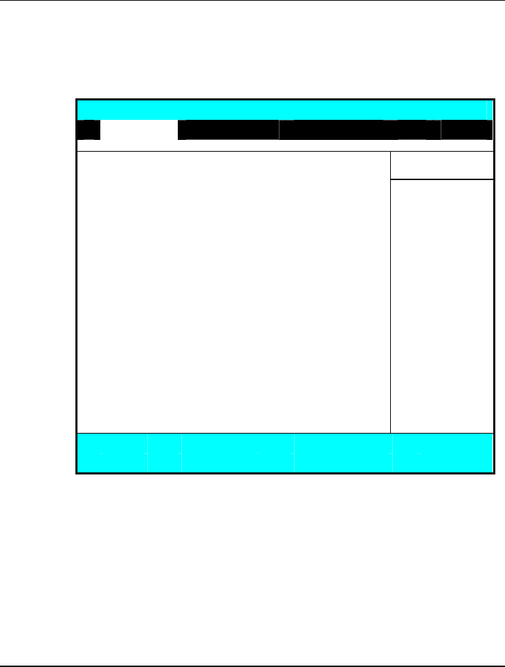
Notebook User Guide
136
6.2 Using the Main Menu Setup
Phoenix BIOS Setup Utility
Main Advanced Security Boot Exit
Item Specific Help
System Time: [07:54:32]
System Date: [10/12/2007] <Tab>, <Shift-Tab>,
or <Enter> selects
4Primary Master [MATSHITADVD-RAM UJ-85JS-(PM)] field.
4Secondary Master [WDC WD1600BEVS-07RST0-(S1)]
CPU Type Intel (R) Core (TM)2 Duo CPU
CPU Speed T7250 2.0GHz
System Memory: 640 KB
Extended Memory: 1038336 KB
BIOS Version: 0.4A-1471-0011
F1 Help Ç È Select Item -/+ Change Values F9 Setup Defaults
Esc Exit Å--> Select Menu Enter Select Sub-Menu F10 Save and Exit
• System Time
Allows you to change the system time using the hour: minute: second
format of the computer.
Enter the current time for reach field and use the <Tab>,
<Shift>+<Tab>, or <Enter> key to move from one field or back to
another.
You can also change the system time from your operating system.

Customizing Your Notebook 6
137
• System Date
Allows you to set the system date using the month/date/year format.
Enter the current time for reach field and use the <Tab>,
<Shift>+<Tab>, or <Enter> key to move from one field or back to
another.
You can also change the system time from your operating system.
• IDE Primary/Master
This field displays various parameters for the hard disk drive. If type
[Auto] is selected, the system automatically sets these parameters. If type
[User] is selected, Cylinders, Heads and Sectors and other value can be
edited.
• SATA Port 1
This field is for information only as the BIOS automatically detects the
drive.
• CPU Type
This field reports the CPU type information detected by the BIOS during
Power-On Self-Test (POST).
• CPU Speed
This field reports the CPU speed information detected by the BIOS
during Power-On Self-Test (POST).
• System Memory
This field reports the amount of base (or conventional) memory found by
the BIOS during Power-On Self-Test (POST).
• Extended Memory
This field reports the amount of extended memory found by the BIOS
during Power-On Self-Test (POST).
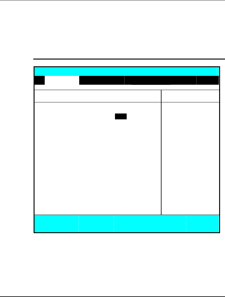
Notebook User Guide
138
• BIOS Version
This field is for information only as the BIOS displays the BIOS version
during the Power-On Self-Test (POST).
6.2.1 PRIMARY MASTER SUB-MENU
Phoenix BIOS Setup Utility
Main
Primary Master [MATSHITADVD-RAM UJ-85JS-(PM)] Item Specific Help
User =
y
ou enter
Type: [Auto] parameters of hard-disk
drive installed at this
Multi-Sector Transfers: [Disabled] connection.
LBA Mode Control: [Disabled] Auto = autotypes hard-
32 Bit I/O: [Disabled] disk drive installed here.
Transfer Mode: [FPIO 4 / DMA 2] CD-ROM = a CD-ROM
Ultra DMA Mode: [Mode 2] drive is installed here.
ATAPI Removable =
removable disk drive is
installed here.
F1 Help Ç È Select Item -/+ Change Values F9 Setup Defaults
Esc Exit Å--> Select Menu Enter Select Sub-Menu F10 Save and Exit
Use the Type field to select the drive type installed. You can select different
drive types as CD-DVD, User, Auto or None by pressing <Space> bar. Set
this option to Auto so your computer will automatically detect the drive type
during power on. Set this option to None when your computer is not installed
any devices. Press <Esc> to return to the Main Menu.
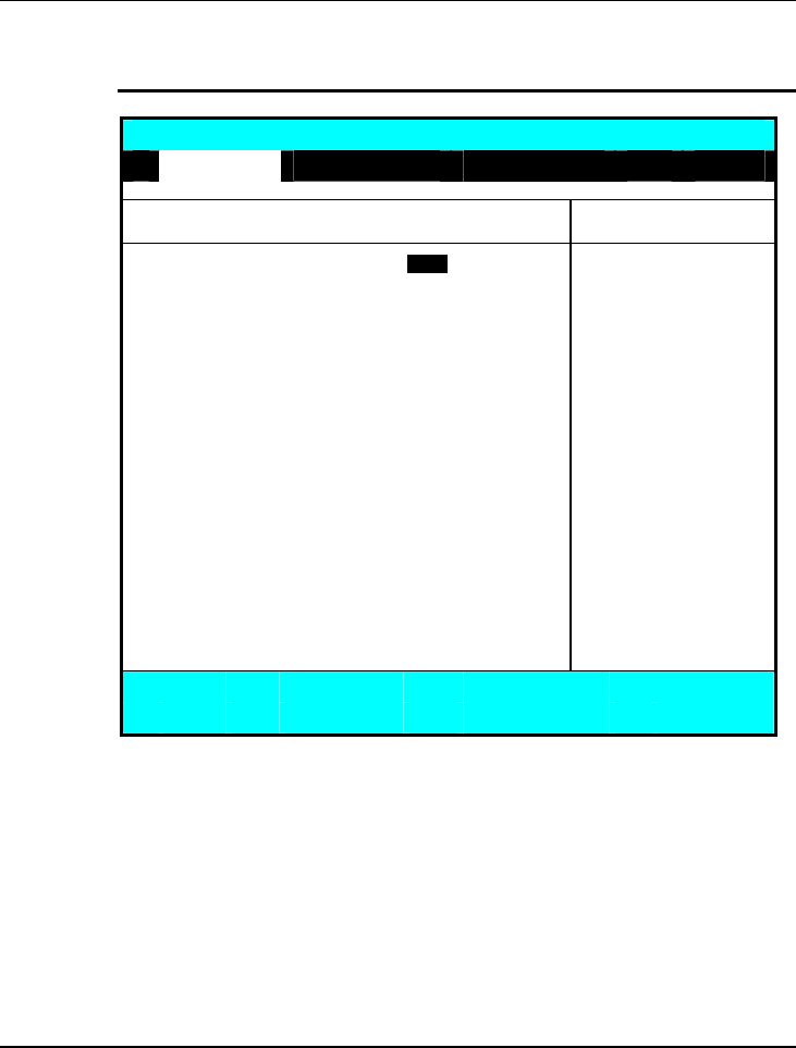
Customizing Your Notebook 6
139
6.2.2 SECONDARY MASTER SUB-MENU
Phoenix BIOS Setup Utility
Main
Secondary Master [WDC WD1600BEVS-07RST0-(S1)] Item Specific Help
T
yp
e:
[
Auto
]
User =
y
ou ente
r
LBA Format parameters of hard-disk
Total Sector: 312581808 drive installed at this
Maximum Capacity: 160GB SATA1 connection.
Auto = autotypes
Multi-Sector Transfers: [16 Sectors] hard-disk drive
LBA Mode Control: [Enabled] installed here.
32 Bit I/O: [Disabled] CD-ROM = a CD-ROM
Transfer Mode: [FPIO 4 / DMA 2] drive is installed here.
Ultra DMA Mode: [Mode 5] ATAPI Removable =
removable disk drive is
installed here.
F1 Help Ç È Select Item -/+ Change Values F9 Setup Defaults
Esc Exit Å--> Select Menu Enter Select Sub-Menu F10 Save and Exit
Use the Type field to select the drive type installed. You can select different
drive types by pressing <Space> bar. Set this option to Auto so your
computer will automatically detect the drive type during power on. Set this
option to None when your computer is not installed any devices. Press <Esc>
to return to the Main Menu.
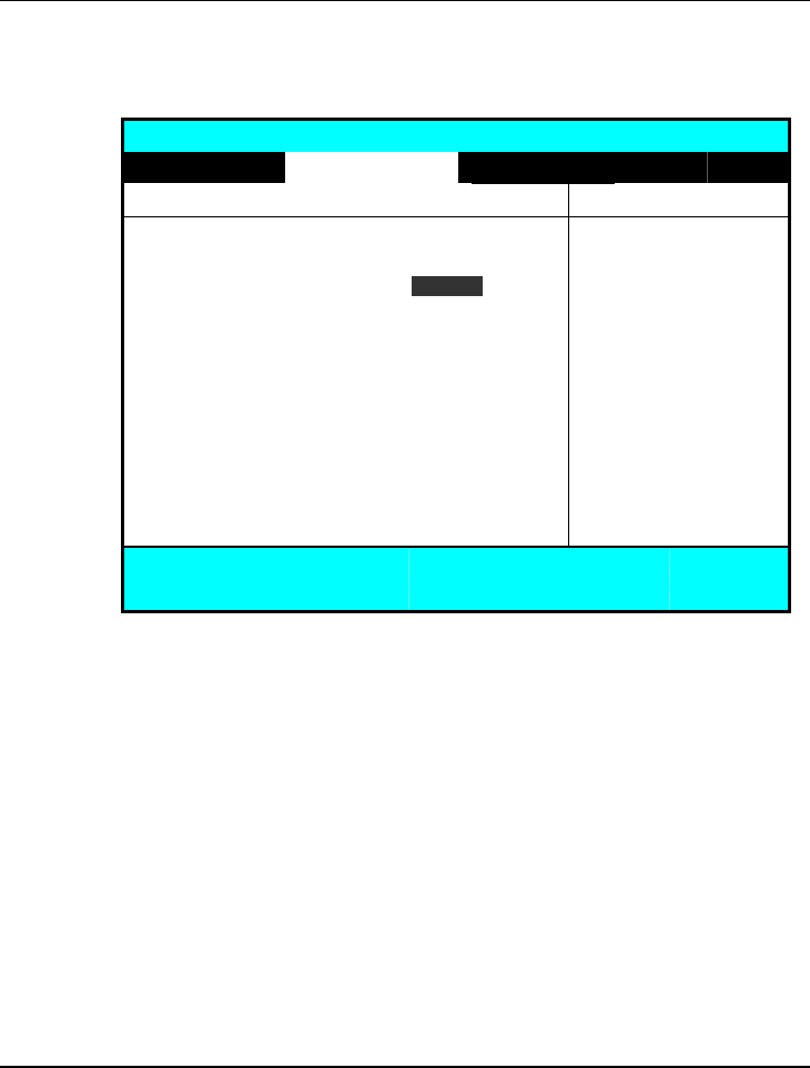
Notebook User Guide
140
6.3 Using the Advanced CMOS Setup
Phoenix BIOS Setup Utility
Main Advanced Security Boot Exit
Item Specific Help
Legacy USB Support [Enabled] Enable support for
Disable Logo screen: [Disabled] Legacy Universal Serial Bus
SATA – Device 31, Function 2: [Enhanced]
AHCI Configuration: [Enabled]
F1 Help Ç È Select Item -/+ Change Values F9 Setup Defaults
Esc Exit Å--> Select Menu Enter Select Sub-Menu F10 Save and Exit
• Legacy USB Support
Enable or disable the USB Bus support when in connection with USB
device.
• Disable Logo Screen
Lets you display POST screen or Logo screen by choosing “Enabled” or
“Disabled”, respectively.
• SATA – Device 31, Function 2:
This function lets you choose “Compatible” or “Enhanced” to define the
SATA or PATA controller mode. For enabling the AHCI configuration,
you should choose “Enhanced” option first.
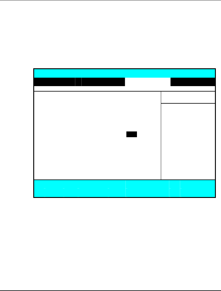
Customizing Your Notebook 6
141
• AHCI Configuration
Lets you choose “Enabled” or “Disabled” to activate or inactive the
AHCI mode for Windows Vista driver.
6.4 Using Security Menu Setup
Phoenix BIOS Setup Utility
Main Advanced Security Boot Exit
Item Specific Help
Supervisor Password Is: Clea
r
User Password Is: Clear Supervisor Password
controls access to the
Set Supervisor Password [Enter] setup utility.
Set User Password [Enter]
Fixed disk boot sector [Normal]
Password on boot [Disabled]
F1 Help Ç È Select Item -/+ Change Values F9 Setup Defaults
Esc Exit Å--> Select Menu Enter Select Sub-Menu F10 Save and Exit
• Supervisor Password Is
Set/Clear selections show that the notebook is under controlled by
Supervisor Password or not.
• User Password Is
Set/Clear selections show that the notebook is under controlled by User
Password or not.

Notebook User Guide
142
• Set Supervisor Password
Supervisor password gives you the authority in accessing the setup utility.
You also need to enter this password in system booting and resuming
from suspend mode. When you press <Enter> in this field, the Set
Supervisor Password dialog box appears. Enter a new password with up
to 8 alpha-numeric characters, and then re-enter it for confirmation.
• Set User Password
This field is only available when Supervisor Password has set. Enter the
user password when boot the system or resume from suspend mode. But
if the Write Protect is set in the Fixed disk boot sector field, you should
enter a supervisor password to access the fixed disk when boot the system
or resume from suspend mode.
• Fixed disk boot sector
If you set this field to Write Protect, the write protect boot sector on hard
disk will protect against viruses. In this situation, only the supervisor can
access the Boot Sector of fixed disk.
• Password on Boot
If you set this field to Enabled, your computer will always ask for the
password every time you boot your computer.
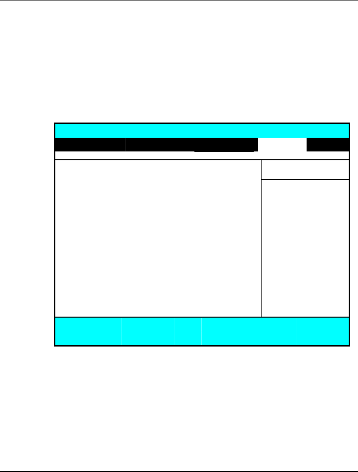
Customizing Your Notebook 6
143
6.5 Using the Boot Setup
This item allows you to set the search drive sequence where the system will try
to boot up first.
Phoenix BIOS Setup Utility
Main Advanced Security Boot Exit
Item Specific Help
Boot priority order Ke
y
s used to view or
IDE CD: MATSHITADVD-RAM UJ-85JS-(PM) configure devices:
IDE HDD: WDC WD1600BEVS-07RST0-(S1) Up and Down arrows
PCI BEV: IBA GE Slot 008C8 v 1245 select a device.
<+> and <-> moves
Excluded from boot order: the device up or down
<x> exclude or include
the device to boot
F1 Help Ç È Select Item F5/F6 Change Values F9 Setup Defaults
Esc Exit Å--> Select Menu Enter Execute Command F10 Save and Exit
This page allows you to set the search drive sequence where the system will try
to boot up first.
To select the boot device, you can setup “Enabled” or “Disabled” for booting
from LAN, or you can search drive sequence by using the up or down arrow
key, then press <+> to move up the device in the list or press <-> to move
down the device in the list. To exit from this menu, press <Esc>.
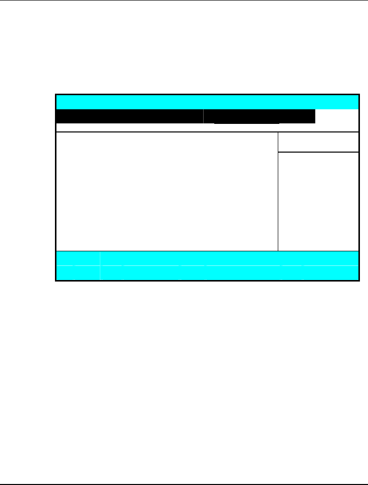
Notebook User Guide
144
6.6 How to Exit the Setup Program
There are two choices to escape from the Setup program.
Phoenix BIOS Setup Utility
Main Advanced Security Boot Exit
Item Specific Help
Exit Saving Changes Exit S
y
stem Setu
p
Exit Discarding Changes and save your
Load Setup Defaults changes to CMOS.
Discard Changes
Save Changes
F1 Help Ç È Select Item F5/F6 Change Values F9 Setup Defaults
Esc Exit Å--> Select Menu Enter Execute Command F10 Save and Exit
• Exit Saving Changes
Saves all changes to CMOS while running the BIOS setup program and
exit from the system setup program.
• Exit Discarding Changes
Allows you to discard all changes made while running the BIOS setup
program and exit from the system setup program.
• Load Setup Defaults
Lets you load the default values for all setup items.
• Discard Changes
Load previous values from CMOS for all SETUP items.

Customizing Your Notebook 6
145
• Saving Changes
Save Setup data to CMOS.
6.7 How to Upgrade the BIOS
Your computer uses EPROM Flash BIOS chip that allows you to easily
upgrade the BIOS program. When you update the BIOS, any customized
settings you made are lost.
To upgrade the BIOS:
1. Put in the BIOS Update data into the USB device.
2. Power on the system with the USB device inserted in the USB port.
3. On the DOS prompt, type the following command.
A:\>Phlash XXXXXX.ROM (BIOS filename) or
A:\>XXXXXX.BAT (Batch file for BIOS file)
Press <Enter> to run this BIOS utility. After the system has been
successfully run this program, a message similar to the following appears:
Flash memory has been successfully programmed,
press any key to restart the system. If the
system does not restart, turn it off, then turn
on again.
4. Press any key to restart this system.
Contact your dealer for the latest BIOS update file.
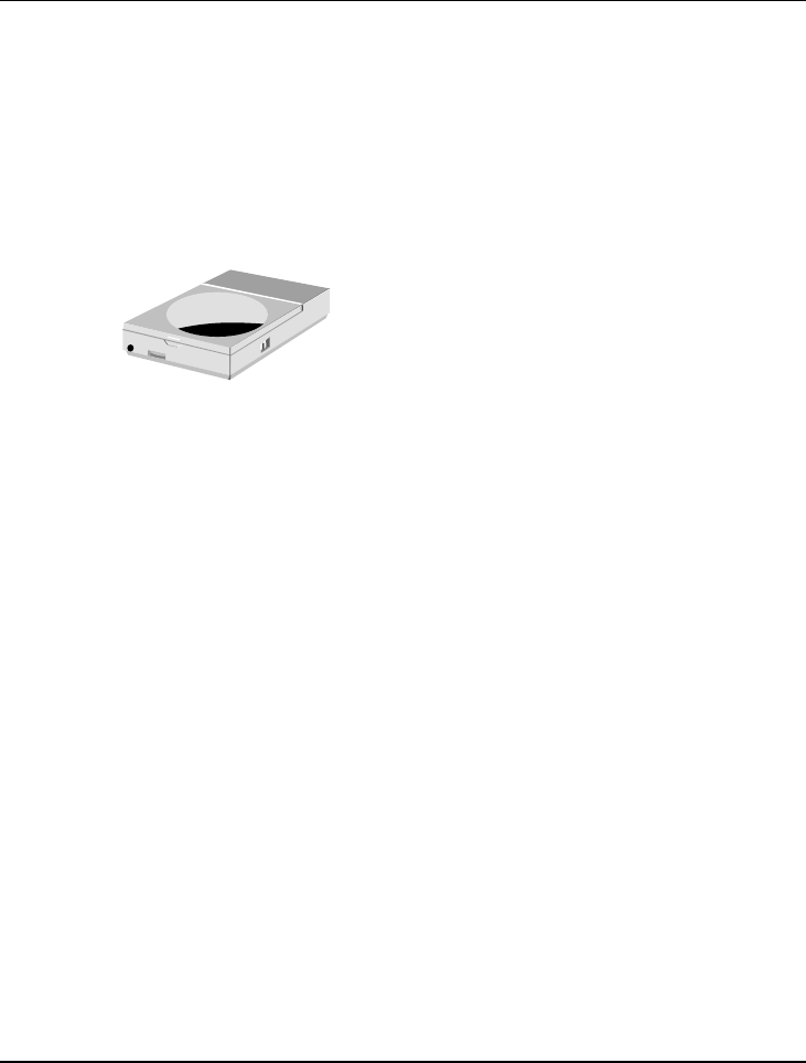
Using Options 7
147
7 Using Options
This chapter describes the advanced features and
expandable architecture in your notebook. You can
upgrade your system for specific requirements.
Notebook User Guide
148
System Upgrade
This section provides some steps in doing system upgrade for your notebook
computer. The upgrade procedures include the following:
7.1 Memory Upgrade
Your notebook computer offers 200-pin SODIMM (Small Outline Dual Inline
Memory Module) at least 512 MB DDRII-SDRAM. The memory
compartment is located inside your computer. The table below lists the
possible combinations of different memory module and memory size.
Please contact dealer for changing or adding DDRII-SDRAM module. It is
not available for users to change it by themselves.
Based Memory Installing Memory Total
512 MB 0 MB 512 MB
512 MB 512 MB 1024 MB
512 MB 1024MB 1536 MB
512 MB 2048MB 2560 MB
1024MB 0 MB 1024 MB
1024MB 512 MB 1536 MB
1024MB 1024MB 2048 MB
1024MB 2048MB 3072 MB
2048MB 0 MB 2048 MB
2048MB 512 MB 2560 MB
2048MB 1024MB 3072 MB
2048MB 2048MB 4096 MB
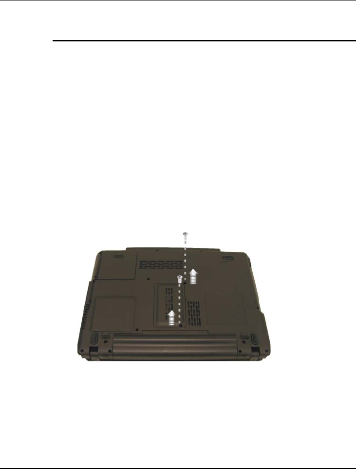
Using Options 7
149
INSTALLING MEMORY MODULE
Your computer comes with standard 512MB, 1024MB or 2048 MB of
synchronous DDRII SDRAM. You can increase system memory to a
maximum of 4096 MB in the system, by installing two small outline double
inline memory modules (SO-DIMMs) with installed base memory in the
system.
The 512MB, 1024MB and 2048MB memory modules are available:
To install the memory module:
1. Make sure the system is powered off, the battery also is removed and that
no peripheral devices are attached.
2. Turn the computer upside-down and locate the screws that secure the
DIMM door at the underside of the notebook.
3. Remove the screws and open the DIMM cover by your finger.
4. Locate the memory module into the empty memory module sockets.
(Your system comes with one memory module already installed in the
socket.)
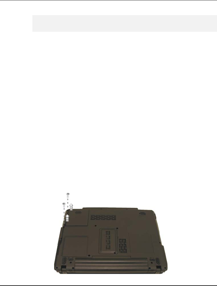
Notebook User Guide
150
Avoid touching the exposed components inside the system. Doing so may
damage the system.
5. Insert the connector of the memory module into the socket. Make sure
the notch of the memory module fits the nose of the socket.
y Hold the memory module at a 30-degree angle and push its
connector into the memory socket of the notebook.
y Press down on the edge of the memory module until the locking
tabs on both sides is locked.
6. Put the DIMM door back and secure the screw on the DIMM door.
7. Turn the system over.
To remove a memory module, push the locking tabs aside from the memory
module until the module pops up. Then, remove the memory module.
7.2 Hard Disk Upgrade
Your notebook computer offers one 2.5" format, 9.5mm height hard disk. If
the volume does not fit your need or it is crashed, you can upgrade it by
replacing with new hard disk. Please do the following steps to change it.
1. Remove the screw and open the cover by lifting its upper side cover.

Using Options 7
151
2. Take out the hard disk from the compartment by finger carefully
3. Remove the connector from the hard disk gently.
4. Remove the crane screws located at each side of the hard disk.
5. Rotate and tighten the crane screws to the new hard disk.
6. Attach the connector to the new hard disk precisely.
7. Place the hard disk back to the compartment.
8. Cover the lid, then rotate and tighten the screws.
9. Set the boot device as DVD/CD-RW Combo drive and Primary Master
as Auto on BIOS setup menu. Please refer to Chapter 6 about the setting
of BIOS setup menu. Then, boot the system by using WinVista CD-ROM
and the system will detect the hard disk automatically and prompt you
how to format the new disk.
Please tighten the screws located at each side of the hard disk before
operating the hard disk. Any vibration may cause damage for the running
hard disk.
Please contact dealer or certified technician for changing the hard disk
drive. The damage of changing HDD resulting from users may not be
under warranty
7.3 Wireless Module Installation
This computer uses mini card wireless LAN module for wireless connection.

Notebook User Guide
152
Please contact dealer for adding or changing this module. Any damage that
caused by inappropriately adding or changing this module will not be under
warranty

Caring for Your Notebook 8
153
8 Caring for Your
Notebook
Your Notebook PC is a fully compatible portable
personal computer with the latest features in mobile
computing and multimedia technology. Lightweight
and compact, your Notebook PC runs on a whole
wide range of general business, personal productivity,
and professional applications, it is ideal for use in the
office, at home, and on the road.
Your Notebook PC also allows you for several levels
of customization and expansion that are previously
available only on desktop PCs.

Notebook User Guide
154
8.1 Important Safety Instructions
Portable computers take the most beating from end users. This section gives
you detailed information about how to maintain a safe working environment
while using the notebook computer. You can maintain its condition and
performance by following these guidelines. Please read it carefully to ensure
maximum safety.
• Before cleaning the notebook computer, make sure it is disconnected
from any external power supplies (i.e. AC adapter, car adapter and so on).
• When cleaning, do not use liquid or sprayed detergent for cleaning.
Instead, use moisture sheet or a cloth for cleaning.
• The socket-outlet shall be installed near the notebook computer and shall
be easily accessible.
• Please keep the notebook computer from humidity.
• Lay the notebook computer on a reliable surface when installing. A drop
or fall may cause injury.
• The openings on the enclosure are for air convection hence the notebook
computer can be protected from overheating. DO NOT COVER THE
OPENINGS.
• Be careful of using power supply. The notebook computer has specific
power requirements.
• Use only a power adapter approved for use with this notebook computer.
• The power adapter may have a 2-prong plug. This is an important safety
feature. A compatible outlet is required. If it is not available, find a
qualified electrician to install one.

Caring for Your Notebook 8
155
• While unplugging the power cord, disconnect it by the plug head, not by
its wire.
• Make sure the socket and any extension cords you may use can support
the total current load of all the connected devices.
• Though your AC adapter is suitable for universal international voltage, it
still requires a stable and continual power supply. Make sure the voltage of
the power source when connect the notebook computer to the power
outlet. If your are unsure of your local power specifications, consult your
dealer or local power company.
• Place the power cord in such a way that people can not step on it. Do not
place anything over the power cord.
• All cautions and warnings on the notebook computer should be noted.
• If the notebook computer is not in use for a long time, disconnect it from
mains to avoid possible damage by transient over-voltage.
• Never pour any liquid into openings as this may cause fire or electrical
shock.
• Never open the body of notebook computer. For safety reason, the
notebook computer should only be opened by qualified service personnel.
• If one of the following situations arises, have the notebook computer
checked by service personnel:
The power cord or plug is damaged.
Liquid has penetrated into the notebook computer.
The notebook computer has been exposed to moisture.
The notebook computer has not worked well or you can not get it
work according to user’s manual.

Notebook User Guide
156
The notebook computer has dropped and damaged.
The notebook computer has obvious sign of breakage.
• Do not leave this notebook computer in an environment unconditioned.
Storage temperature above 60ºC (140ºF) may damage the notebook
computer.
• An approved power cord has to be used for the notebook computer’s
power supply. For a rated current up to 6A and an equipment weight
more than 3 kg, a power cord not lighter than H05VV-F, 2G, 0.75mm2,
has to be used.
• To avoid any damage happened to the internal device, you should first
disconnect the AC adapter and remove the battery pack from the
notebook when replacing any internal device.
The sound pressure level at the operator's position according to IEC 60704-1
is equal or less than 70dB(A).
8.2 Cleaning Your Computer
When it is necessary to clean the plastic case and keyboard, use a soft, lint-free
cloth, slightly dampened with a mild detergent solution or use the contents of
any commercially available computer cleaning kit.
Never use alcohol, petroleum-based solvents, or harsh detergents to clean the
notebook. Also never spray any liquids directly on the computer case,
keyboard, or screen. If the liquid-crystal display (LCD) screen has become
smeared or dusty, clean the screen by first applying a mild glass cleaner to a
soft, clean, lint-free cloth, and gently wipe the glass. Never apply liquids
directly on the screen surface. Moreover, do not use paper towels to clean the
display screen. Paper can scratch the display screen matte.

Caring for Your Notebook 8
157
8.3 Maintaining the LCD Quality
When it comes to screen problems, heat plays a big part. After a good working
session, the typical routine is to shut the machine and close the cover. But the
display surface - no matter what type it is - and the components inside the
computer radiates heat; when you close the cover, you trap the heat against the
screen. Leave the computer's cover open for about ten minutes while the heat
disperses. Make this a habit.
You should also enable the power management of your computer to turn off
the LCD power and display when the system is in inactivity for some time.
Adding screen savers is also acceptable.
Follow the safety guidelines mentioned earlier and how to clean your
computer.
8.4 Maintaining Your Hard Disk
Losing your data has the same consequences as a system break down. Users
must make it a habit of doing hard disk maintenance every week or so. Here is
some maintenance you could do:
• Always back up your data files from your hard disk.
• Install the virus detecting program to monitor virus that could tamper
your files.
• Use SCANDISK once in a while to correct any errors found in the
directory and File Allocation Table. This will also free up space from any
unused sectors.
• Never move or raise the computer while the hard disk is being accessed,
most especially don't jar the hard disk as this may cause a hard disk crash.

Notebook User Guide
158
• Use hard disk maintenance programs like Disk Defragmenter of
Windows. These reorganize your hard disk by eliminating fragmentation
and improving your hard disk access time.
• Install a system password in your computer so others won't be able to use
the hard disk.
8.5 Battery Care Guidelines
The battery pack furnished with the computer requires reasonable care and
handling to ensure efficient operation and maximum life. There is a risk of fire
and chemical burn if the battery pack is handled improperly.
To ensure that the battery pack endures normal life cycle, always observe the
following precautions when handling the battery pack:
• Handle batteries carefully. Do not try to disassemble, crush, puncture,
open, drop, mutilate, short external contacts, disposed of in water or fire,
or expose it to temperatures higher than 60 C.
• Recharge batteries only as described in this manual and only in ventilated
areas. Never use an external charger other than the one supplied with your
computer.
• Do not leave batteries in hot locations for more than a day or two.
• Do not leave your battery in your computer for longer than 1 month
without plugging in the power adapter.
• Do not leave battery in storage for more than 2 months without
recharging it to prevent over discharge. Over discharge will hurt the
battery
• Dispose dead battery properly to protect the environment. The batteries
contain hazardous chemicals and should not be thrown out with
household or office trash.

Caring for Your Notebook 8
159
• You should always discharge your battery before recharging it on either of
these two conditions: first, this is the first time you start to use your
battery; second, you had not charge the battery for more than 2 months.
To discharge the battery, please execute the "Battery Refresh" function in
the BIOS Setup Utility.
8.6 When You Travel
For safety and convenience when traveling, please follow these instructions:
• Back up all needed files on your hard disk before traveling.
• Recharge your battery overnight to ensure full battery power before you
leave.
• Don't forget to bring along the AC adapter and extra battery pack.
• Try to bring backup software as well.
• Check the voltage rating and the outlet type of your destination. If the
power cord of the adapter is different, then you need to purchase a
suitable one. Consult your dealer.
• Carry your computer in its carrying case or in a briefcase. Never check-in
the computer as a luggage.
• Remember to apply those power saving features and techniques to save
battery power.

Notebook User Guide
160
This page is intended to be blank.

System Specification A
161
APPENDIX A
System Specification
This appendix gives information on the technical
and hardware specifications of your computer. Please
note that the information mentioned here may not be
exactly the same with your computer as specification
is subject to change without notice or modifying this
manual.
Designed with an advanced modular architecture,
your Notebook PC also allows you for several levels
of customization and expansion that are previously
available only on desktop PCs.

Notebook User Guide
162
PROCESSOR UNIT
• Intel® CoreTM 2 Duo processor
T5450/T5550 for 1.66/1.66 GHz, 667MHz FSB, 2MB integrated L2
cache for the processor.
• Intel® CoreTM 2 Duo processor
T7250 for 2.00 GHz, 800MHz FSB, 2MB integrated L2 cache for the
processor.
• Intel® CoreTM 2 Duo processor
T7300/T7500 for 2.0/2.2 GHz, 800MHz FSB, 4MB integrated L2 cache
for the processor.
SYSTEM MEMORY
• Two 200-pin memory slots.
• User-upgradeable to maximum 4GB using 200-pin SODIMM 512MB,
1024MB or 2048MB modules
• DDRII –667 SDRAM modules
LCD DISPLAY
• 13.3" WXGA Color TFT LCD, 1280x800
• Maximum 16M true colors on all LCD display
VGA SYSTEM
• Embedded with Intel GM965 graphic engine
• Maximum 16 million colors on LCD display at 1280x800 resolution for
13.3" LCD

System Specification A
163
• Maximum 16 million colors on external monitor or projector at
1280x1024 resolution (Non-Interlaced)
STORAGE
• 2.5” Format 9.5mm High SATA HDD Module; Bus Mastering, Ultra
DMA ATA-150 Support for LBA Scheme
• Enhanced IDE bootable DVD Dual or DVD Super-Multi drive module
• 4-in-1 (SD, MS, MMC, and MS_Pro) card reader
AUDIO SYSTEM
• Compliant with Intel HD Audio (Azalia).
• H/W Audio Sound Blaster 16 compatible
• Audio input jacks for microphone (MIC)
• Audio output jack for external speaker or headphone (Line-Out)
• Digitized audio SPDIF port for high quality signal transmission.
• Sound volume adjust by K/B Hot-Keys
EXPRESSCARD
One 54mm, 26-pin ExpressCard slot
TOUCHPAD
Integrated touchpad (Serial/USB mouse) pointing device with 2 click buttons

Notebook User Guide
164
KEYBOARD
• Full-sized 87-keys keyboard with Windows systems hot-keys, inverted T-
cursor keys, 10 hot keys, 12 function keys, and embedded numeric keypad
• Provides international language keyboard
FLASH BIOS
512K Flash ROM BIOS for easy BIOS upgrade
I/O PORTS
• 1 x VGA Port
• 3 x Universal Serial Bus (USB 2.0)
• 4 in 1 Card Reader Socket
• 1 x IEEE 1394 port (BTO)
• 1 x 10/100/1000 Mbps LAN port
WIRELESS DEVICES
Intel® Wireless WiFi Link 4965AGN Network Connection (802.11a/b/g/n),
Mini Card.
AC/DC POWER SUPPLY ADAPTER
Universal auto-switching (100V~240V) 65W adapter, 20 Volt
BATTERY
• Rechargeable 6 Cells Li-ion battery pack with Smart Battery function
• Approximately 3 Hours (for Battery Mark) Battery Life

System Specification A
165
WEIGHT AND DIMENSION
• 328 (W) x 247 (D) x 36.6 ~ 38 (H) mm
• Approximately 2.3 kg