Fisher & Paykel DD24DCX7 88637 A User Manual DISHWASHER Manuals And Guides 1509230L
User Manual: Fisher & Paykel DD24DCX7-88637-A DD24DCX7-88637-A FISHER & PAYKEL DISHWASHER - Manuals and Guides View the owners manual for your FISHER & PAYKEL DISHWASHER #DD24DCX788637A. Home:FISHER & PAYKEL:/ Dishwasher Parts:FISHER & PAYKEL dishwasher parts:#DD24DCX788637A FISHER & PAYKEL dishwasher parts:#DD24DCX788637A FISHER & PAYKEL dishwasher manual
Open the PDF directly: View PDF ![]() .
.
Page Count: 20
iNSTALLATiON iNSTRUCTiONS
DishDrawer TM dishwasher
DD24D 7 & DD24DT 7 models
US CA
Fisher Paykel
_90204D 04'/3
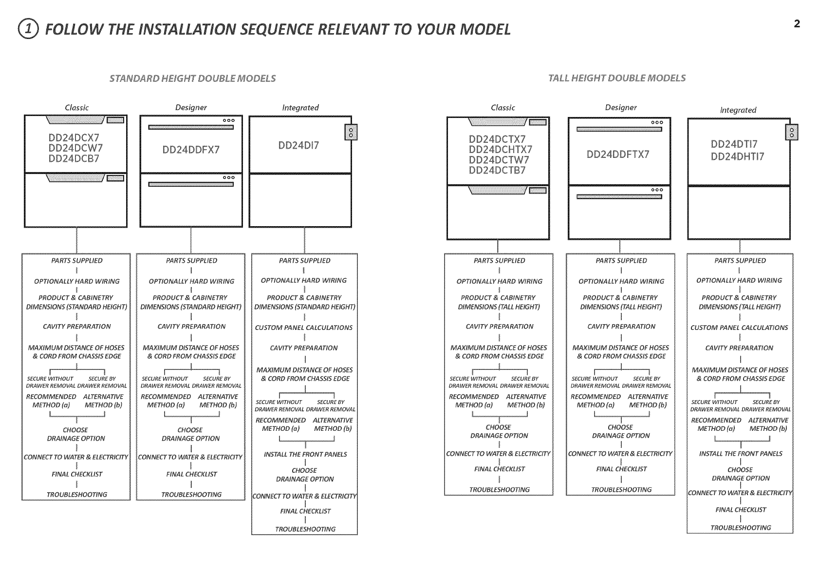
FOLLOW THE INSTALLATION SEQUENCE RELEVANT TO YOUR MODEL
STANDARD HEIGHT DOUBLE MODELS TALL HEIGHT DOUBLE' MODELS
CIassic
DD24DCX7
DD24DCW7
DD24DCB7
Designer
ooo
DD24DDFX'7
ooo
F
Integrated CIassic Designer
/ooo
DD24DI7 E] DD24DCTX7
DD24DCHTX7
DD24DCTW7
DD24DCTB7
DD24DDFTX'7
000
Integrated
DD24DTI7
DD24DHTJ7
i
PARTS SUPPLIED
OPTIONALLY HARD WIRING
PRODUCT & CABINETRY
DIMENSIONS (STANDARD HEIGHT)
CAVITY PREPARATION
m
MAXIMUM DISTANCE OF HOSES
& CORD FROM CHASSIS EDGE
,L
l ]
SECURE WITHOUT SECURE BY
DRAWER REMOVAL DRAWER REMOVAL
RECOMMENDED ALTERNATIVE
METHOD (a) METHOD (b)
J
T
CHOOSE
DRAINAGE OPTION
CONNECT TO WATER & ELECTRICITY
FINAL CHECKLIST
TROUBLESHOOTING
PARTS SUPPLIED
OPTIONA LLY HA RD WIRING
PRODUCT & CABINETRY
DIMENSIONS (STANDARD HEIGHT)
CAVITY PREPARATION
MAXIMUM DISTANCE OF HOSES
& CORD FROM CHASSIS EDGE
f
SECURE WITHOUT SECURE BY
DRAWER REMOVAL DRAWER REMOVAL
RECOMMENDED ALTERNATIVE
METHOD (a) METHOD (b)
L
CHOO5E
DRAINAGE OPTION
CONNECT TO WATER & ELECTRICITY
FINAL CHECKLIST
l
TROUBLESHOOTING
PARTS SUPPLIED
OPTIONALLY HARD WIRING
M
PRODUCT & CABINETRY
DIMENSIONS (STANDARD HEIGHT)
CUSTOM PANEL CALCULATIONS
CA VITY PREPA RATION
MAXIMUM DISTANCE OF HOSES
& CORD FROM CHASSIS EDGE
[
SECURE WITHOUT SECURE BY
DRAWER REMOVAL DRAWER REMOVAL
RECOMMENDED ALTERNATIVE
METHOD (a) METHOD (b)
W
INSTALL THE FRONT PANELS
CHOOSE
DRAINAGE OPTION
CONNECT TO WATER & ELECTRICIT_
FINAL CHECKLIST
TROUBLESHOOTING
PARTS SUPPLIED
OPTIONALLY HARD WIRING
PRODUCT & CABINETRY
DIMENSIONS (TALL HEIGHT)
CA VITY PREPA RATION
MAXIMUM DISTANCE OF HOSES
& CORD FROM CHASSIS EDGE
i
f 1
SECUREWITHOUT SECUREBY
DRAWER REMOVAL DRAWER REMOVAL
RECOMMENDED ALTERNATIVE
METHOD (a) METHOD (b)
L J
7
CHOO5E
DRAINAGE OPTION
CONNECT TO WATER & ELECTRICITY
FINAL CHECKLIST
TROUBLESHOOTING
]
PARTS SUPPLIED
OPTIONALLY HARD WIRING
PRODUCT & CABINETRY
DIMENSIONS (TALL HEIGHT)
CAVITY PREPARATION
MAXIMUM DISTANCE OF HOSES
& CORD FROM CHASSIS EDGE
f
SECURE WITHOUT SECUREBY
DRAWER REMOVAL DRAWER REMOVAL
RECOMMENDED ALTERNATIVE
METHOD (a) METHOD (b)
L
CHOO5E
DRAINAGE OPTION
CONNECT TO WATER & ELECTRICITY
FINAL CHECKLIST
TROUBLESHOOTING
T
PARTS SUPPLIED
OPTIONALLY HARD WIRING
PRODUCT & CABINETRY
DIMENSIONS (TALL HEIGHT)
CUSTOM PANEL CALCULATIONS
CA VITY PREPA RATION
MAXIMUM DISTANCE OF HOSES
& CORD FROM CHASSIS EDGE
[
SECURE WITHOUT SECUREBY
DRAWER REMOVAL DRAWER REMOVAL
RECOMMENDED ALTERNATIVE
METHOD (_) METHOD (b)
J
INSTALL THE FRONT PANELS
CHOOSE
DRAINAGE OPTION
CONNECT TO WATER & ELECTRICITY
FINAL CHECKLIST
TROUBLESHOOTING
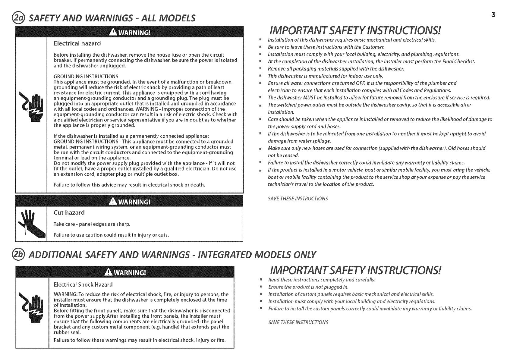
SAFETY AND WARNINGS-ALL MODELS
Electrical hazard
Before installing the dishwasher, remove the house fuse or open the circuit
breaker. If permanently connecting the dishwasher, be sure the power is isolated
and the dishwasher unplugged.
GROUNDING INSTRUCTIONS
This appliance must be grounded. In the event of a malfunction or breakdown,
grounding wi[[ reduce the risk of electric shock by providing a path of least
resistance for electric current. This appliance is equipped with a cord having
an equipment-grounding conductor and a grounding plug. The plug must be
plugged into an appropriate outlet that is installed and grounded in accordance
with all local codes and ordinances. WARNING - Improper connection of the
equipment-grounding conductor can result in a risk of electric shock. Check with
a qualified electrician or service representative if you are in doubt as to whether
the appliance is properly grounded.
If the dishwasher is installed as a permanently connected appliance:
GROUNDING INSTRUCTIONS -This appliance must be connected to a grounded
metal, permanent wiring system, or an equipment-grounding conductor must
be run with the circuit conductors and connected to the equipment-grounding
terminal or lead on the appliance.
Do not modify the power supply plug provided with the appliance - if it will not
fit the outlet, have a proper outlet installed by a qualified electrician. Do not use
an extension cord, adapter plug or multiple outlet box.
Failure to follow this advice may result in electrical shock or death.
Cut hazard
Take care - panel edges are sharp.
Failure to use caution could result in injury or cuts.
3
installation of this dishwasher requires basic mechanical and electrical skills.
Be sure to leave these instructions with the Customer
installation must comply with your local building, electricity, and plumbing regulations.
At the completion of the dishwasher installation, the installer must perform the Final Checklist.
Remove all packaging materials supplied with the dishwasher
This dishwasher is manufactured for indoor use only.
Ensure all water connections are turned OFF. it is the responsibility of the plum ber and
electrician to ensure that each installation complies with all Codes and Regulations.
The dishwasher MUST be installed to allow for future removal from the enclosure if service is required.
The switched power outlet must be outside the dishwasher cavity, so that it is accessible after
installation.
Care should be taken when the appliance is installed or removed to reduce the likelihood of damage to
the power supply cord and hoses.
ff the dishwasher is to be relocated from one installation to another it must be kept upright to avoid
damage from water spillage.
Make sure only new hoses are used for connection (supplied with the dishwasher). Old hoses should
not be reused.
Failure to install the dishwasher correctly could invalidate any warranty or liability claims.
ff the product is installed in a motor vehide, boat or similar mobile facility, you must bring the vehicle,
boat or mobile facility containing the product to the service shop at your expense or pay the service
technician's travel to the location of the product.
SAVETHESEINSTRUCTIONS
ADDITIONAL SAFETY AND WARNINGS- INTEGRATED MODELS ONLY
Electrical Shock Hazard
WARNING: To reduce the risk of electrical shock, fire, or injury to persons, the
installer must ensure that the dishwasher is completely enclosed at the time
of installation.
Before fitting the front panels, make sure that the dishwasher is disconnected
from the power supply.After installing the front panels, the installer must
ensure that the following components are electrically grounded: the panel
bracket and any custom metal component (e.g. handle) that extends past the
rubber sea[.
Failure to follow these warnings may result in electrical shock, injury or fire.
Read these instructions completely and careful_yo
Ensure the product is not plugged in.
Installation of custom panels requires basic mechanical and electrical skills.
installation must comply with your local building and electricity regulations.
Failure to install the custom panels correctly could invalidate any warranty or liability claims.
SAVETHESEINSTRUCTIONS
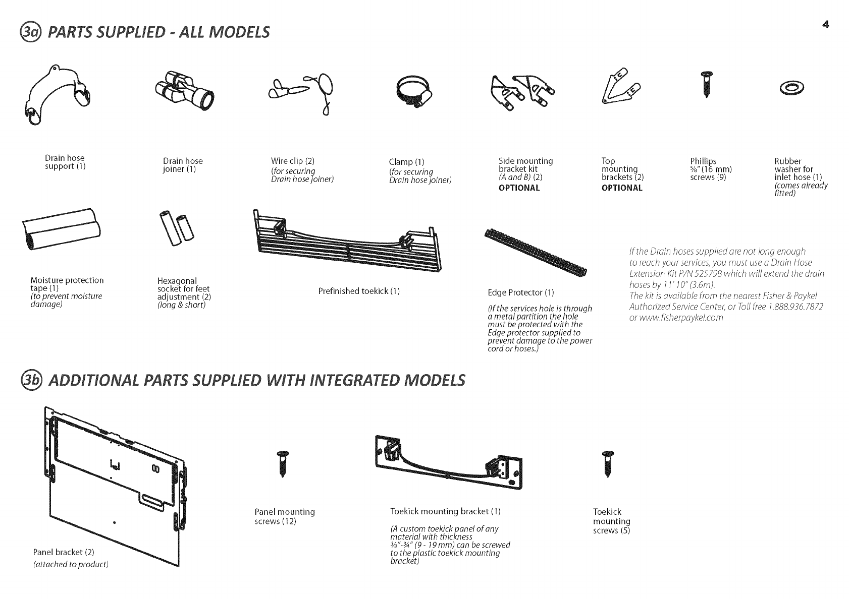
PARTS SUPPLIED °ALL MODELS 4
Drain hose Drain hose Wire clip (2) Clamp (1) Side mounting Top Phillips Rubber
support (1) joiner (1) (for securing (for securing bracket kit mounting %" (16 mm) washer for
Drain hosejoiner) Drain hose joiner) (A and B) (2) brackets (2) screws (9) inlet hose (1)
OPTIONAL OPTIONAL (comes already
fitted)
Moisture protection Hexagonal
tape (1) . socket for feet
(to prevent mois[ure adjustment (2)
damage) (long & short)
Prefinished toekick (1)
ADDITIONAL PARTS SUPPLIED WITH INTEGRATED MODELS
Edge Protector (1)
(If the services hole is through
ametal partition the hole
must be protected with the
Edge protector supplied to
prevent damage to the power
cord or hosesJ
/f the Droin hosessupplied ore not long enough
to reoch your services,you must useo Droin Hose
f!_'tensionKit P/N 525Y98 which will extend the droin
hosesby 11' 70" (Zdm).
fhe kit isovoi/ob/e from the neorest Fisher& PoyM/
Authorized _Serviced2nter, or fb// free 1.888.93d./872
or www.fisherpoykel.com
Panel bracket (2)
(attached to product)
Panel mounting
screws (12) Toekick mounting bracket (1)
(A custom toekickpanel of any
material with thickness
_"-_" (9 -19 ram) can be screwed
to the plastic toekick mounting
bracket)
Toekick
mounting
screws (5)
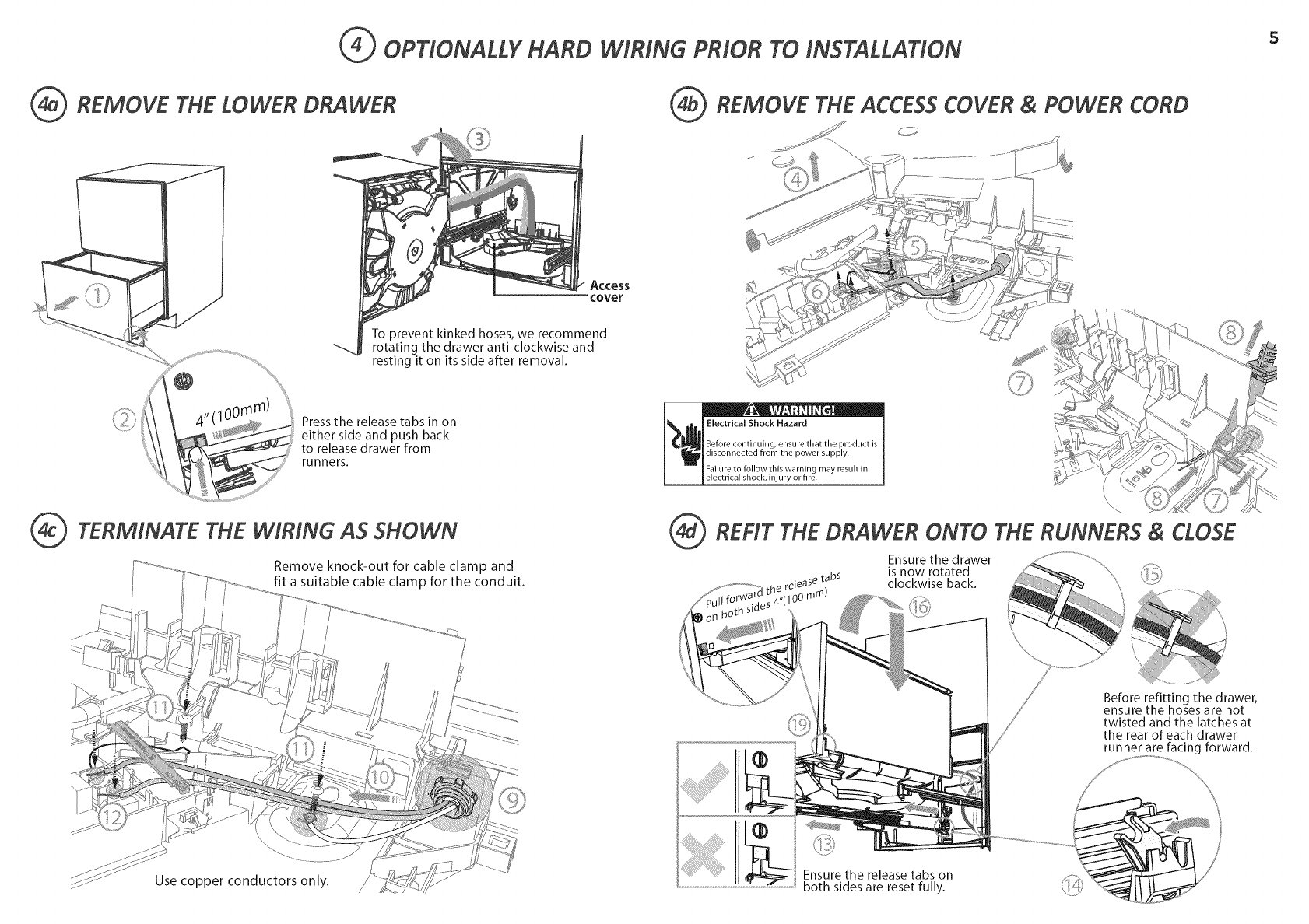
QOPTIONALLY HARD
_ REMOVE THE LOWER DRAWER
WIRING PRIOR TO INSTALLATION
REMOVE THE ACCESS COVER & POWER CORD
Access
cover
/
To prevent kinked hoses, we recommend
rotating the drawer anti-clockwise and
resting it on its side after removal.
Press the release tabs in on
either side and push back
to release drawer from
runners.
TERMINATE THE WIRING AS SHOWN
Remove knock-out for cable clamp and
fit a suitable cable clamp for the conduit.
\\
Use copper conductors only.
Electrical Shock Hazard
Before continuing, ensure that the product is
disconnected from the power supply.
Failure to follow this warning may result in
electrical shock, injury or fire.
\\
REFIT THE DRAWER ONTO THE RUNNERS & CLOSE
Ensure the drawer
is now rotated
tabs
,release clockwise back.
;'(1O0ram)
Before refitting the drawer,
ensure the hoses are not
twisted and the latches at
the rear of each drawer
runner are facing forward.
Ensure the release tabs on
both sides are reset fully.
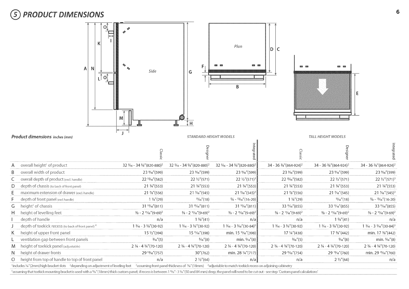
(5( PRODUCT DIMENSIONS
K
A
n_
I
Side
Plan D C
6
Product dimensions inches(mm) STANDARD HEf,GH'T'MODEL,_ ?_LL HE#GH'T' MODELS
F depth of front panel (exchande) 1 1/8"(29) 11A6"(18) % - 1¾6"(16-20) 1 Y8"(29) 1¼6"(18) % - lSA6"(16-20)
G height ofchassis 31 I%6"(811) 31 15Z6"(811) 31 15_6"(811) 331¼6"(855) 331¼6"(855) 331¼6"(855)
H heightof levellingfeet Y8- 2 11_6"(9-69) 2 3/8 - 2 11_6"(9-69) 2 3/8 - 2 11_6"(9-69)2 3/8- 2 11_6"(9-69)2 3/8- 2 11_6"(9-69) 2 3/8 - 2 11_6"(9-69)2
I depth of handle n/a 1%"(41) n/a n/a 1%"(41) n/a
J depth of toekick recess(toback of front panel)1 3_6 - 3 s/8"(30-92) 13_6 - 3 5/8"(30-92) 13_6 - 3 5_6"(30-84) 5 13_6 - 3 5/8"(30-92) 13_6 - 3 5/8"(30-92) 13_6 - 3 5_6"(30-84) 5
Kheight of upper front pane[ 15 1/2"(394) 15 1¼6"(398) min. 15 11A6"(398) 17 1/4"(438) 17 3/8"(442) min. 17 3/8"(442)
LventiDtion gap between front panels ¾6"(5) 546t'(8) min. sA6"(8) 346"(5) sA6"(8) min. sA6"(8)
M height of toekick panel (adjustabk?) 2 % - 4 3_"(70-120) 2 % - 4 3/4"(70-120) 2 % - 4 3_"(70-120) 2 3__4 3_"(70-120) 2 % - 4 3/4"(70-120) 2 % - 4 3_"(70-120)
Nheight of drawer fronts 291¾6"(757) 30"(762) min. 28 1/4"(717) 291¼6"(754) 29 lSA6"(760) min. 29 lSA6"(760)
0 height from top of handle to top of front panel n/a 2 Y2"(64) n/a n/a 2 1/2"(64) n/a
UnchdesXJ'(2mm) high bracket slots 2dependingon adjustment of levelingfeet _assumingfFont_:s_ne[thicknessof 1}46'(18mm) _adjustableto match toekick recesson adjoining cabinetry
Sassumingthat toekick mounting bracketis usedwith a%/'(18ram) thick custom panel; if _'ecessisbetwe_:n1 _'_J'-3%/'(50 and tY/_ram) dee:p, the panel will need to be cut out - seestep 'Custompanel calcuDtion{
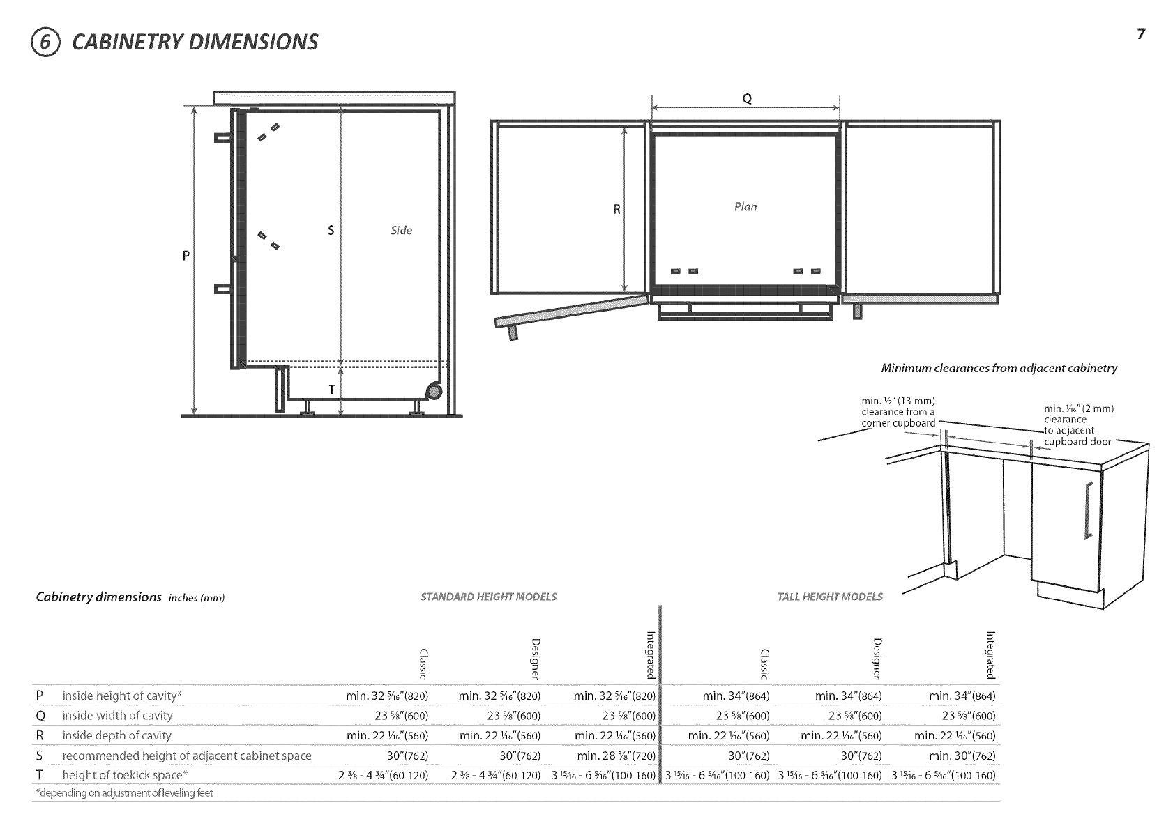
CABINETRY DIMENSIONS
Cabinetry dimensions inches(mm)
Side
Q
Plan
Minimum clearances from adjacent cabinetry
STANDARD HE_GH'T' MODEL,_
rain. W'(13 mm)
clearancefrom a min. ho"(2 ram)
corner cupboard --_____,_ clearance
:........... H_. -'-'---_-_.to adjacent
_upboard door
'T_LLHE_GH'T'MODEL,_
P inside height of c_vity _ rain. 32 %o"(820) min. 32 sAo"(820) min. 32 sAo"(820) rain. 34"(864) min. 34"(864) rain. 34"(864)
Q inside width of cavity 23 %"(600) 23 %"(600) 23 %"(600) 23 %"(600) 23 %"(600) 23 %"(600)
R inside depth of cavity rain. 22 ¼o"(s60) min. 22 ¼o"(560) rain. 22 ¼6"(560) rnin. 22 ¼o"(s60) rnin. 22 ¼o"(s60) rnin. 22 Ho"(s60)
S recommended height of adjacent cabinet space 30"(762) 30"(762) min. 28 3/8"(720) 30"(762) 30"(762) min, 30"(762)
T heightoftoekickspace _ 23/8-43A'(60-120) 23/8-43/4"(60-120) 3_sA6-6sA6"(lO0-160) 3_sA6-6sA6"(lO0-160) 3_sA6-6sA6"(lO0-160) 3_sA6-6sA6"(lO0-160)
_dependin9 on adjustment oflevelin9 feet
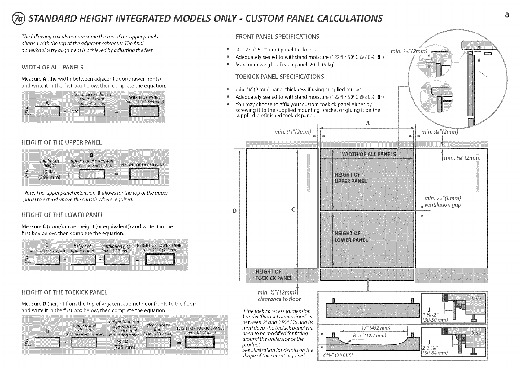
7(7( STANDARD HEIGHT INTEGRATED MODELS ONLY- CUSTOM PANEL CALCULATIONS
The following calculations assume the top of the upper panel is
aligned with the top of the adjacent cabinetry. The final
panel/cabinetry alignment is achieved by adjusting the feet:
WIDTH OF ALL PANELS
Measure A (the width between adjacent door/drawer fronts)
and write it in the first box below, then complete the equation.
FRONTPANEL SPECiFiCATiONS
%- 13A6"(16-20 ram) panel thickness
Adequately sealed to withstand moisture (122%/50°C @ 80% RH)
Maximum weight of each panel: 20 Ib (9 kg)
TOEKICK PANEL SPECiFiCATiONS
rain. 3/8"(9 ram) panel thickness if using supplied screws
Adequately sealed to withstand moisture (122°F/50°C @80% RH)
You may choose to affix your custom toekick panel either by
screwing it to the supplied mounting bracket or gluing it on the
supplied prefinished toekick panel.
A
min_ _,_J'(2mm)
HEIGHT OFTHE UPPERPANEL
Note: The'upperpanel extension' Ballows for the top of the upper
panel to extend above the chassiswhere required.
HEmGHT OF THE LOWER PANEL
Measure C (door/drawer height (or equivalent)) and write it in the
first box below, then complete the equation.
\
lmino _46"(2mm)
mino5/i_"(Smm)
_ventfladon g@
8
HEmGHT OF THE TOEKJCK PANEL
Measure D (height from the top of adjacent cabinet door fronts to the floor)
and write it in the first box below, then complete the equation. If the toekick recess (dimension
Junder 'Product dimensions') is
between 2" and 3 _" (50 and 84
mm) deep, the toekick panel will
need to be modified for fitting
around the underside of the
product.
See illustration for details on the
shape of the cutout required.
17" (432 ram)
R_/_"(1Z7 ram)
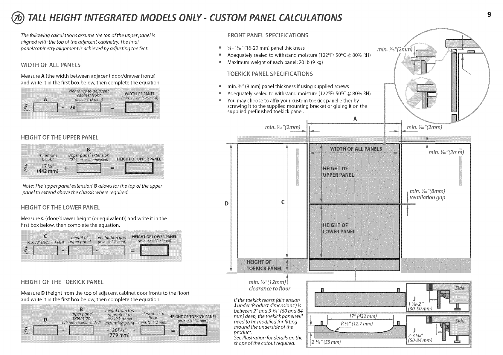
TALL HEIGHT INTEGRATED MODELS ONLY- CUSTOM PANEL CALCULATIONS
The following calculations assume the top of the upper panel is
aligned with the top of the adjacen t cabinetry. The final
panel/cabinetry alignment is achieved by adjusting the feet:
WIDTH OF ALL PANELS
Measure A (the width between adjacent door/drawer fronts)
and write it in the first box below, then complete the equation.
FRONTPANEL SPECiFiCATiONS
%- 13A6"(16-20 ram) panel thickness
Adequately sealed to withstand moisture (122%/50°C @ 80% RH)
Maximum weight of each panel: 20 Ib (9 kg)
TOEKICK PANEL SPECiFiCATiONS
rain. 3/8"(9 ram) panel thickness if using supplied screws
Adequately sealed to withstand moisture (122°F/50°C @80% RH)
You may choose to affix your custom toekick panel either by
screwing it to the supplied mounting bracket or gluing it on the
supplied prefinished toekick panel.
A
min_ _,_J'(2mm)
HEIGHT OFTHE UPPERPANEL
Note: The'upperpanel extension' Ballows for the top of the upper
panel to extend above the chassiswhere required.
HEmGHT OF THE LOWER PANEL
Measure (::(door/drawer height (or equivalent)) and write it in the
first box below, then complete the equation.
\
lmino _46"(2mm)
mino5/i_"(Smm)
_ventfladon g@
9
HEmGHT OF THE TOEKJCK PANEL
Measure D (height from the top of adjacent cabinet door fronts to the floor)
and write it in the first box below, then complete the equation. If the toekick recess (dimension
Junder 'Product dimensions') is
between 2" and 3 _" (50 and 84
mm) deep, the toekick panel will
need to be modified for fitting
around the underside of the
product.
See illustration for details on the
shape of the cutout required.
17" (432 ram)
R_/_"(1Z7 ram)
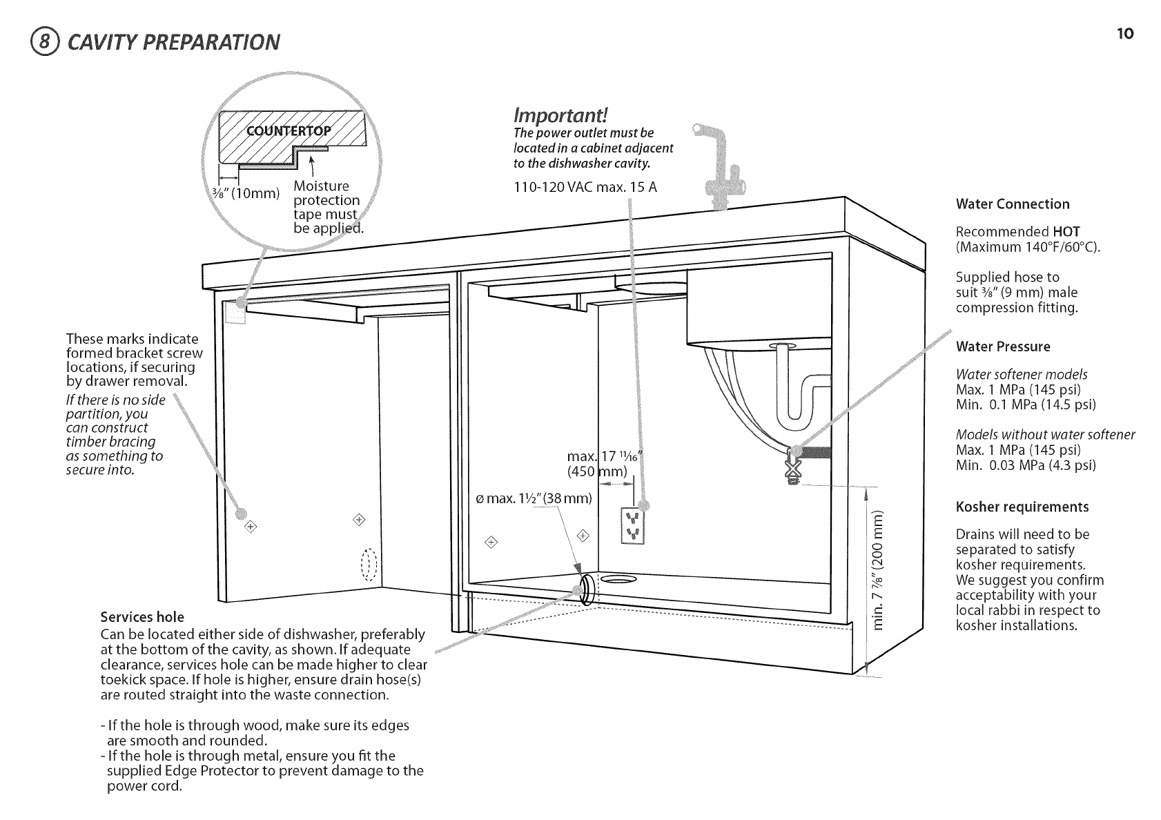
CAWTY PREPARATION 10
ii!i
....3 ,Moisture
(10mm) protection
t a
These marks indicate
formed bracket screw
locations, if securing
by drawer removal.
If there is no side
partition, you
can construct
timber bracing
as something to
secure into.
÷
Services hole
Can be located either side of dishwasher, preferably
at the bottom of the cavity, as shown. If adequate
clearance, services hole can be made higher to clear
toekick space. If hole is higher, ensure drain hose(s)
are routed straight into the waste connection.
- If the hole is through wood, make sure its edges
are smooth and rounded.
- If the hole is through metal, ensure you fit the
supplied Edge Protector to prevent damage to the
power cord.
lmportand
Thepower outlet must be
located in a cabinet adjacent
to the dishwasher cavity.
110-120VAC max. 15 A
max,
(450
Omax. 11/2"(38mm)
\\
\\
Water Connection
Recommended HOT
(Maximum 140°F/60°C).
Supplied hose to
suit %" (9 mm) male
compression fitting.
i i
...... Water Pressure
Water softener models
Max. 1 MPa (145 psi)
Min. 0.1 MPa (14.5 psi)
Models without water softener
Max. 1 MPa (145 psi)
Min. 0.03 MPa (4.3 psi)
Kosher requirements
Drains will need to be
separated to satisfy
kosher requirements.
We suggest you confirm
acceptability with your
local rabbi in respect to
kosher installations.
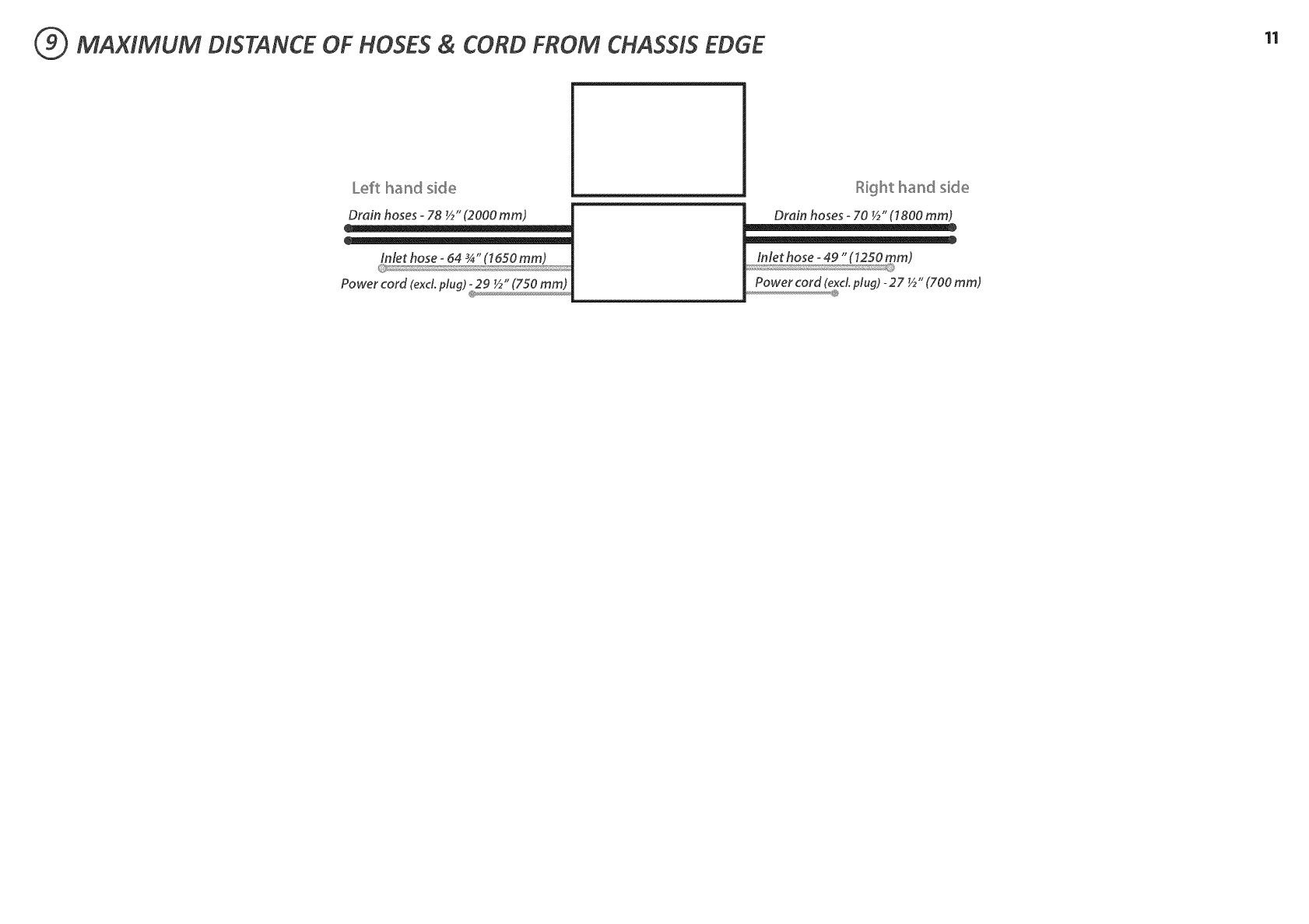
(_ MAXIMUM DISTANCE OF HOSES & CORD FROM CHASSIS EDGE 11
Left hand side
Drain hoses -78 ½" (2000 mm)
Inlet hose _64 _" (7650 mm)
Power cord (exd. plug)
Right hand side
Drain hoses -70 ½" (7800 mm)
Power cord (excLplug) -27 ½" (700 mm)
@
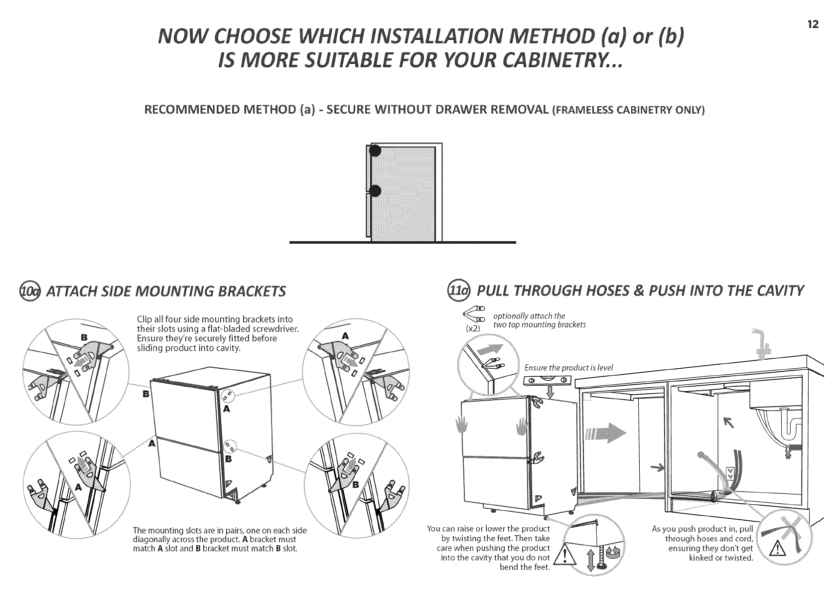
NOW CHOOSE WHICH INSTALLATION METHOD (a)
IS MORE SUITABLE FOR YOUR CABINETRY...
12
RECOMMENDED METHOD (a) ° SECURE WnTHOUT DRAWER REMOVAL (FRAMELESS CABINETRY ONLY}
_ATTACH SIDE MOUNTING BRACKETS
Clip all four side mounting brackets into
their slots using a flat-bladed screwdriver.
Ensure they're securely fitted before
sliding product into cavity.
(_ PULL THROUGH HOSES PUSH INTO THE CAWTY
&
optionally attach the
(x2) two top mounting brackets
Ensure the product is level
The mounting slots are in pairs, one on each side
diagonally across the product. A bracket must
match A slot and B bracket must match B slot.
You can raise or lower the product
by twisting the feet. Then take
care when pushing the product
into the cavity that you do not
bend the feet.
Asyou push product in, pull
through hoses and cord,
ensuring they don't get
kinked or twisted.
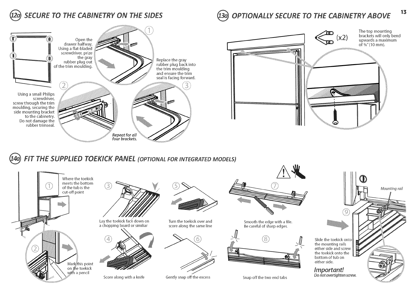
(_ SECURE TO THE CABINETRY ON THE SIDES
Open the
drawer halfway.
Using a fiat-bladed
Using a small Philips
screwdriver,
screw through the trim
moulding, securing the
side mounting bracket
to the cabinetry.
Do not damage the
rubber trimseal.
Repeat for all
four brackets.
Replace the gray
rubber plug back into
the trim moulding
and ensure the trim
seal is facing forward.
@OPTIONALLY SECURETO THE CABINETRY ABOVE 13
x2)
The top mounting
brackets will only bend
upwards a maximum
of 3/8"(10 mm).
@FIT THE SUPPLIED TOEKlCK PANEL (OPTIONAL FORINTEGRATEDMODELS)
Where the toekick
meets the bottom
ofthetubis the
cut-off point Moun ring rail
Lay the toekick fac'e down on
a chopping board or simlllar
Turn the toekick over and
score along the same line
Smooth the edge with a file.
Be careful of sharp edges.
)oint
a pencil
Score along with a knife Gently snap off the excess Snap off the two end tabs
Slide the toeklck onto
the mounting rails
either side and screw
the toekick onto the
bottom of tub on
either side.
Importand
Do not overtighten screw.
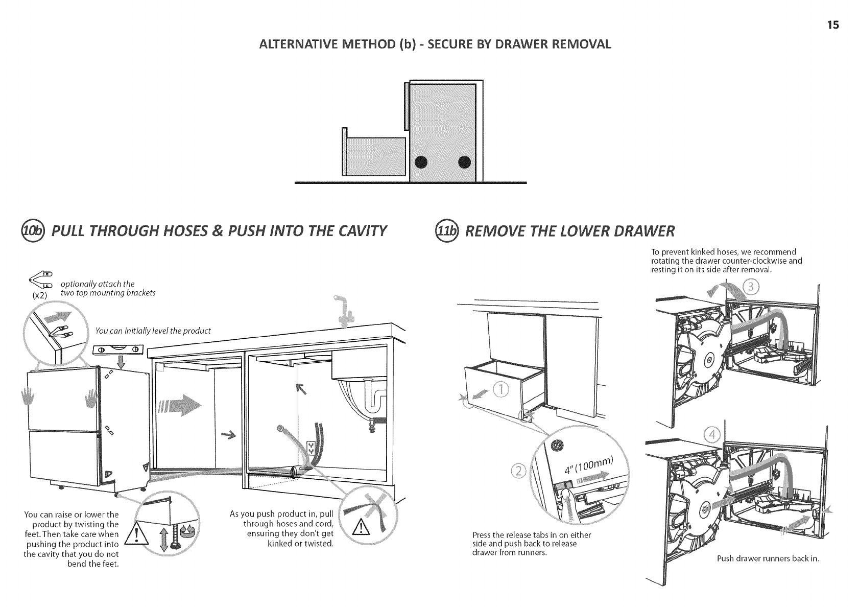
ALTERNATnVE METHOD (b) o SECURE BY DRAWER REMOVAL
15
(_ PULL THROUGH HOSES & PUSH iNTO THE CAWTY
optionally attach the
(x2) two top mounting brackets
You can initially level the product
_i;;;iiii_!iiiiHiiiiiiiiii_¸
%
You can raise or lower the
product by twisting the
feet.Then take care when
pushing the product into
the cavity that you do not
bend the feet.
As you push product in, pull
through hoses and cord,
ensuring they don't get
kinked or twisted.
OREMOVE THE LOWER DRAWER
To prevent kinked hoses, we recommend
rotating the drawer counter-clockwise and
resting it on its side after removal.
4' (100mm)
Press the release tabs in on either
side and push back to release
drawer from runners. Push drawer runners back in.
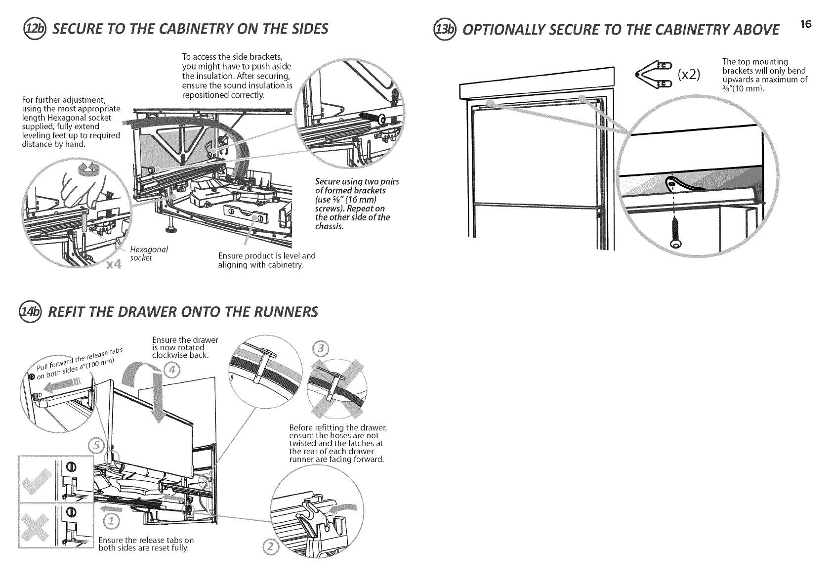
_ SECURE TO THE CABINETRY ON THE SIDES
For further adjustment,
using the most appropriate
length Hexagonal socket
supplied, fully extend
leveling feet up to required
distance by hand.
To accessthe side brackets,
you might have to push aside
the insulation. After securing,
ensure the sound insulation is
repositioned correctly.
Hexagonal
socket
Secure using two pairs
of formed brackets
(use _" (16 mm)
screws). Repeat on
the other side of the
chassis.
Ensure product is level and
aligning with cabinetry.
_REFIT THE DRAWER ONTO THE RUNNERS
Ensure the drawer
is now rotated
clockwise back.
Before refitting the drawer,
ensure the hoses are not
twisted and the latches at
the rear of each drawer
runner are facing forward.
Ensure the release tabs on
both sides are reset fully.
@OPTIONALLY SECURE TO THE CABINETRY ABOVE 16
x2)
The top mounting
brackets will only bend
upwards a maximum of
3/8"(10mm).
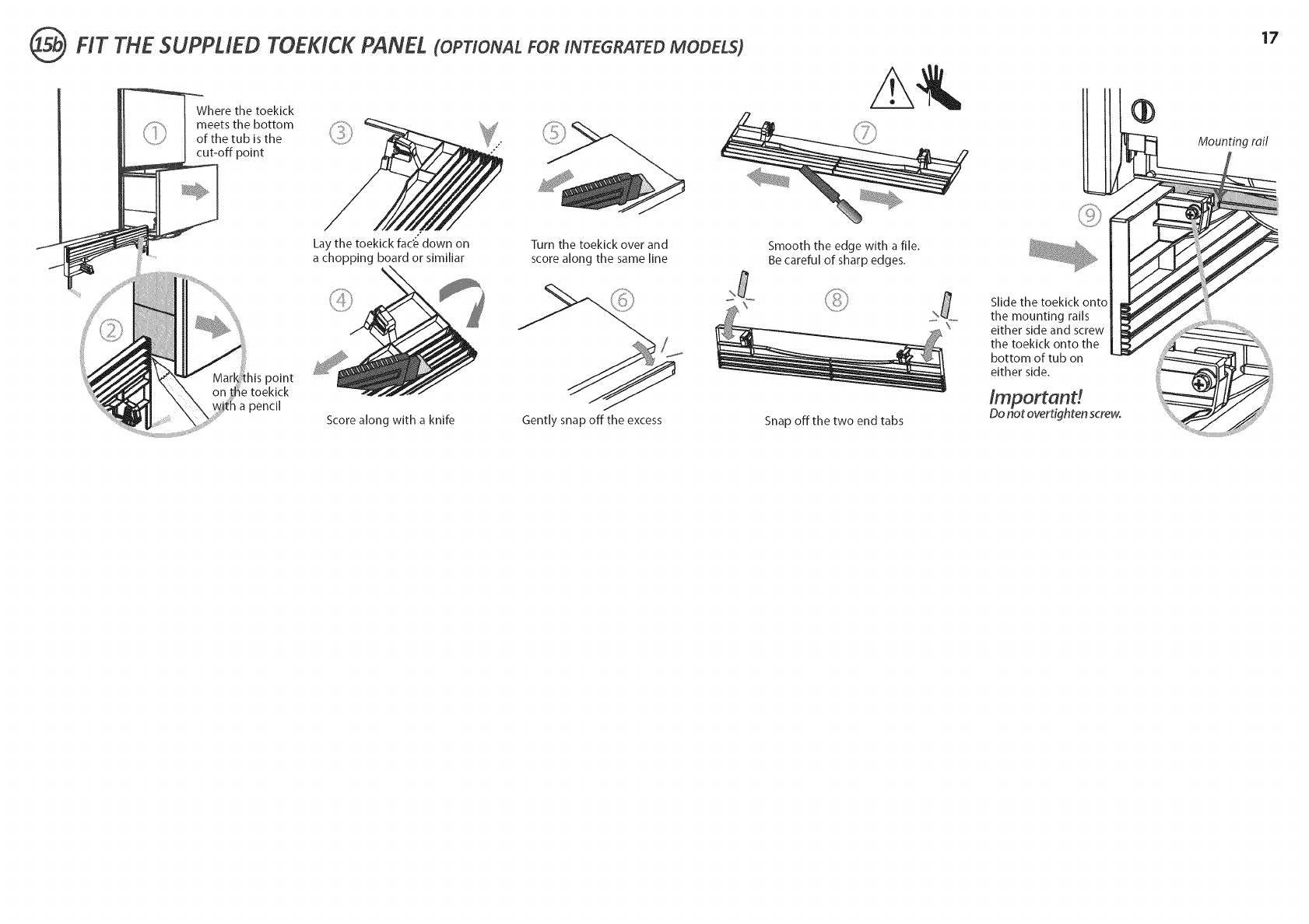
_ HT THE SUPPLED TOEKlCK PANEL (OPTIONAL FORINTEGRATEDMODELS)
Where the toekick
meets the bottom
of the tubisthe
cut-off point
17
Mounting roil
Lay the toekick fac'e down on
a chopping board or simlllar
Turn the toekick over and
score along the same line Smooth the edge with a file.
Be careful of sharp edges.
his point
e toekick
a pencil
Score along with a knife Gently snap off the excess Snap off the two end tabs
Slide the toeklck onto
the mounting rails
either side and screw
the toekick onto the
bottom of tub on
either side.
/mportand
Do not overtiqhten screw.
INTEGRATED MODELS ONLY oINSTALLING THE FRONT PANELS 18
®
®
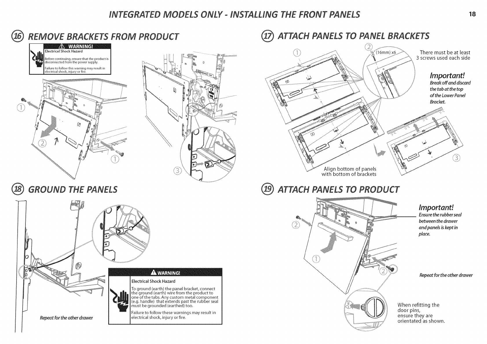
REMOVE BRACKETS FROM PRODUCT
Electrical Shock Hazard
Before continuing, ensure that the product is
disconnected from the power supply.
Failure to follow this warning may result in
electrical shock, injury or fire.
GROUND THE PANELS
Repeat for the other drawer
I
! A •
Electrical Shock Hazard
To ground (earth) the panel bracket, connect
the ground (earth) wire from the product to
one of the tabs. Any custom metal component
(e.g. handle) that extends past the rubber seal
must be grounded (earthed) too.
Failure to follow these warnings may result in
electrical shock, injury or fire.
(i@ ATTACH PANELS TO PANEL BRACKETS
There must be at least
3 screws used each side
Important!
Break off and discard
the tab at the top
of the Lower Panel
Bracket.
Align bottom of panels
with bottom of brackets
(_ ATTACH PANELS TO PRODUCT
Important!
Ensure the rubber seal
between the drawer
and panels is kept in
place.
Repeat for the other drawer
When refitting the
door pins,
ensure they are
orientated as shown.
INTEGRATED MODELS ONLY °INSTALLING THE FRONT PANELS 19
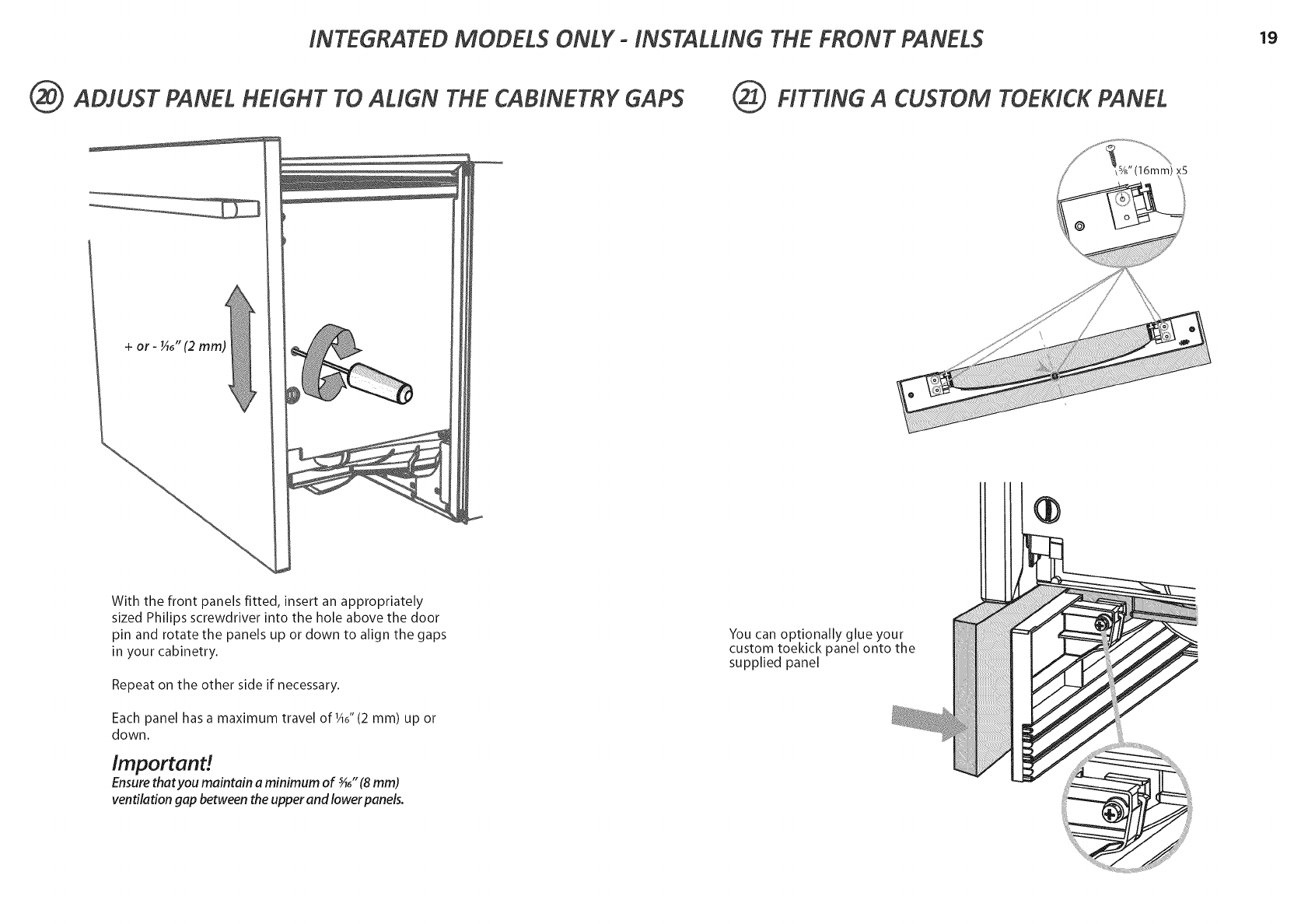
(_ ADJUST PANEL HEIGHT TO ALIGN THE CABINETRY GAPS
+or- _6"
With the front panels fitted, insert an appropriately
sized Philips screwdriver into the hole above the door
pin and rotate the panels up or down to align the gaps
in your cabinetry.
Repeat on the other side if necessary.
Each panel has a maximum travel of_A6"(2 mm) up or
down.
Important!
Ensurethatyou maintain a minimum of _6" (8 mm)
ventilation gap between the upper and lower panels.
(_ FITTING A CUSTOM TOEKICK PANEL
,%" (16mm) x5
@
You can optionally glue your
custom toekick panel onto the
supplied panel
@
@
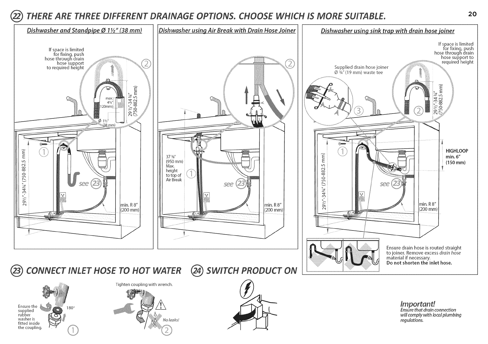
THERE ARE THREE DIFFERENT DRAINAGE OPTIONS. CHOOSE WHICH iS MORE SUITABLE. 2O
Dishwasher and Standpipe 01½" (38 mm)
If space is limited
for fixing, push
hose through drain
hose support
to required height
Dishwasher using Air Break with Drain Hose Joiner
373_ "
(950mm) i
Max.
height
to top of
Air Break
CONNECT iNLET HOSE TO HOT WATER
Tighten coupling with wrench.
2_ SWITCH PRODUCT ON
Dishwasher using sink trap with drain hose joiner
Supplied drain hosejoiner
0 _" (19 ram) waste tee
If space is limited
for fixinq, push
hose through drain
hose support to
required height
HIGHLOOP
min. 6"
(150 mm)
Ensure drain hose is routed straight
to joiner. Remove excess drain hose
material if necessary.
Do not shorten the inlet hose.
Important!
Ensure that drain connection
will comply with Iocal piumbin9
regulations.
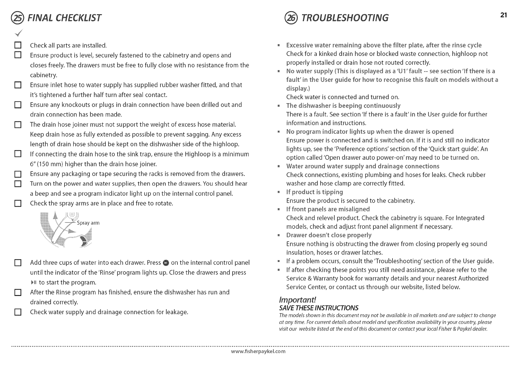
FINAL CHECKLIST TROUBLESHOOTING 21
[] Check all parts are installed.
[] Ensure product is level, securely fastened to the cabinetry and opens and
closes freely. The drawers must be free to fully close with no resistance from the
cabinetry.
[] Ensure inlet hose to water supply has supplied rubber washer fitted, and that
it's tightened a further half turn after seal contact.
[] Ensure any knockouts or plugs in drain connection have been drilled out and
drain connection has been made.
[] The drain hose joiner must not support the weight of excess hose material.
Keep drain hose as fully extended as possible to prevent sagging. Any excess
length of drain hose should be kept on the dishwasher side of the highloop.
[] If connecting the drain hose to the sink trap, ensure the Highloop is a minimum
6" (150 mm) higher than the drain hose joiner.
[] Ensure any packaging or tape securing the racks is removed from the drawers.
[] Turn on the power and water supplies, then open the drawers. You should hear
a beep and see a program indicator light up on the internal control panel.
[] Check the spray arms are in place and free to rotate.
' arm
[] Add three cups of water into each drawer. Press O on the internal control panel
until the indicator of the 'Rinse' program lights up. Close the drawers and press
H_ to start the program.
[] After the Rinse program has finished, ensure the dishwasher has run and
drained correctly.
[] Check water supply and drainage connection for leakage.
o Excessive water remaining above the filter plate, after the rinse cycle
Check for a kinked drain hose or blocked waste connection, highloop not
properly installed or drain hose not routed correctly.
o No water supply (This is displayed as a 'U 1' fault - see section 'If there is a
fauW in the User guide for how to recognise this fault on mode_s without a
Check water is connected and turned on.
o The dishwasher is beeping continuously
There is a fault. See section 'If there is a fault' in the User guide for further
information and instructions.
o No program indicator lights up when the drawer is opened
Ensure power is connected and is switched on. If it is and still no indicator
lights up, see the 'Preference options' section of the 'Quick start guide: An
option called 'Open drawer auto power-on' may need to be turned on.
, Water around water supply and drainage connections
Check connections, existing plumbing and hoses for leaks. Check rubber
washer and hose clamp are correctly fitted.
, If product is tipping
Ensure the product is secured to the cabinetry.
o If front pane_sare misaHgned
Check and relevel product. Check the cabinetry is square. For Integrated
models, check and adjust front panel alignment if necessary.
o Drawer doesn't dose property
Ensure nothing is obstructing the drawer from closing properly eg sound
insulation, hoses or drawer latches.
o If a problem occurs, consult the 'Troubleshooting' section of the User guide.
, If after checking these points you still need assistance, please refer to the
Service & Warranty book for warranty details and your nearest Authorized
Service Center, or contact us through our website, listed below.
Important!
SAVE THESEINSTRUCTIONS
Themodelsshownin thisdocumentmaynot beavailablein all marketsandaresubjectto change
at anytime.Forcurrentdetailsabout modelandspecification availability in yourcountry, please
visitour websitelistedat theendof thisdocumentor con:at:your localFisher&Paykel dealer.
wwwofisherpaykeLcom
