FitLinxx UWM02 Universal Wireless RF Module User Manual EMPED EEPROM PROGRAMMING PROCEDURE
FitLinxx Universal Wireless RF Module EMPED EEPROM PROGRAMMING PROCEDURE
FitLinxx >
Exhibit D Users Manual per 2 1033 b3

SUBJECT:
A&D MEDICAL DIGITAL BLOOD
PRESSURE MONITOR ASSEMBLY
DOCUMENT NUMBER:
910-00059-01
REVISION:
08
PAGE:
1of 18
UMW02
ASSEMBLY
&
TEST SPECIFICATION
910-00059-01
Copyright © 2003-2004 FitSense Technology
Proprietary Information
Revision History
DATE VERSION DESCRIPTION AUTHOR
05/21/08 01 Initial release of document David W Smith
05/22/08 02 Added details to Functional Verification process David W Smith
06/09/08 03 Added FCC labeling details David W Smith
06/24/08 04 Updated rework instructions to reflect UWM in
location of best performance
David W Smith
7/16/08 05 Added details of test application, setup and test
process.
David W Smith
7/17/08 06 Define all distances in meters David W Smith
7/18/08 07 Clarify the use of System test on starting of test
application.
David W Smith
7/25/08 08 Added FCC statement on section 1.1 David W Smith

SUBJECT:
A&D MEDICAL DIGITAL BLOOD
PRESSURE MONITOR ASSEMBLY
DOCUMENT NUMBER:
910-00059-01
REVISION:
08
PAGE:
2of 18
Table of Contents
1 INTRODUCTION.............................................................3
2 INCOMING INSPECTION................................................4
3 INCOMING TEST............................................................4
4 BP MONITOR REWORK INSTRUCTIONS...................10
5 FUNCTIONAL TEST.....................................................11
6 PACKAGING.................................................................18

SUBJECT:
A&D MEDICAL DIGITAL BLOOD
PRESSURE MONITOR ASSEMBLY
DOCUMENT NUMBER:
910-00059-01
REVISION:
08
PAGE:
3of 18
1 INTRODUCTION
1.1 Purpose of this document
The purpose of this document is to specify the assembly and functional test
requirements for the A & D Medical Digital Blood Pressure Monitor with the Universal
Wireless Module (UWM).
This device complies with Part 15 of the FCC Rules. Operation is
subject to the following two conditions: (1) this device may not
cause harmful interference and (2) this device must accept any
interference received, including interference that may cause un-
desired operation.
In adherence to FCC regulations any changes or modifications
not expressly approved by FitSense/FitLinxx could void the
user’s authority to operate the device.
1.2 Document Overview
This document in divided into the following section for organizational purposes.
Incoming Inspection; Describes UWM PCB packaging to be received by A&D
Medical.
Incoming Test; Describes the equipment, setup, and process for incoming test of the
UWM PCB.
Rework Instructions; Describes the wiring and mounting of the UWM PCB in the
Digital Blood Pressure Monitor.
Functional Test; Describes the equipment, setup, and process to Functionally Test
the wireless Blood Pressure Monitor containing the UWM PCB.
2 INCOMING INSPECTION
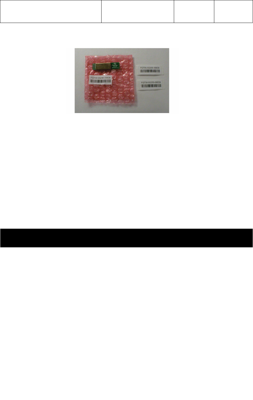
The UWM (P/N 710-00041-01) will be received in an ESD bubble bag with two bar
coded serial number labels and an FCC label as shown below .
SUBJECT:
A&D MEDICAL DIGITAL BLOOD
PRESSURE MONITOR ASSEMBLY
DOCUMENT NUMBER:
910-00059-01
REVISION:
08
PAGE:
4of 18
A ID Number label along with the FCC label is to be adhered to the blood pressure
monitor as described in the BP Monitor Rework Instructions. The second ID Number
label can be used on the product carton, packaging or as the manufacturer deems
appropriate.
The bar coded serial number label contains alpha and numerical characters. The
alpha characters represent the Device ID type as a BP monitor. The numerical
characters represents the Device ID Number plus a checksum. The bar code format is
UPC128.
The UWM PCB can be functionally verified and the corresponding labeling checked
utilizing the Incoming Test process described below. The UWM can be sample tested
per the MIL 105E Level ll Acceptance Plan.
3 INCOMING TEST
3.1 Test Equipment
The following test equipment is required for Incoming Test of the UWM PCB.
●USB based Personal Computer or laptop with Windows XP/2000 O.S. (provided by
A & D Medical)
●Custom Incoming Test Fixture (provided by FitSense)
●3.30vdc power source for the UWM PCB Test Fixture (provided by A & D Medical)
●Digital Multimeter
●Known good ActiLink (provided by FitSense)
●ActiBPMfgTest test application (provided by FitSense)
3.2 UWM Test application
The System Test portion of the ActiBPMfgTest Manufacturing Test application
should be used for Incoming Test of the UWM PCB. When the application is started,
Select the tab for System Test.
The application (ActiBPMfgTest.exe) is installed in the C:\Program Files\ActiBP
Manufacturing Test. The application can be setup as a shortcut on the desktop.

SUBJECT:
A&D MEDICAL DIGITAL BLOOD
PRESSURE MONITOR ASSEMBLY
DOCUMENT NUMBER:
910-00059-01
REVISION:
08
PAGE:
5of 18
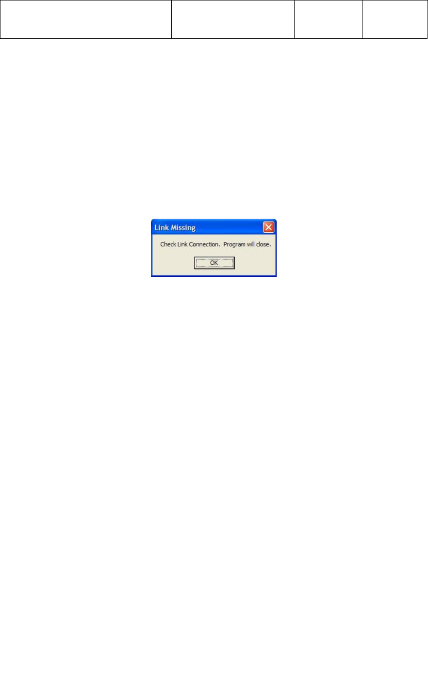
A known good ActiLink must be installed in the USB port of the test PC prior to starting
the application. If no ActiLink is present, or the ActiLink is not functioning properly, an
error message “Check Link Connection, Program will close” will be displayed
and the program will exit when the operator clicks on the “OK” tab as shown below.
The application has a Test Configuration screen which allows manufacturing engineers
to enable/disable tests and set specific test parameters. Test configuration limits that
can be modified include firmware Version and ID Number. To access the Test
Configuration screen, the engineer would select “Edit”, then “Limits”, then enter the
password.
No password is set when the application is first installed. Select “OK” to access the
Test Configuration limits screen for the first time. To setup a password, select
“Edit”, then “Limits”. Select “Advanced”, then select “Password”. Enter the new
password and select “OK”. The new password is now required each time to access
the Test Configuration screen.
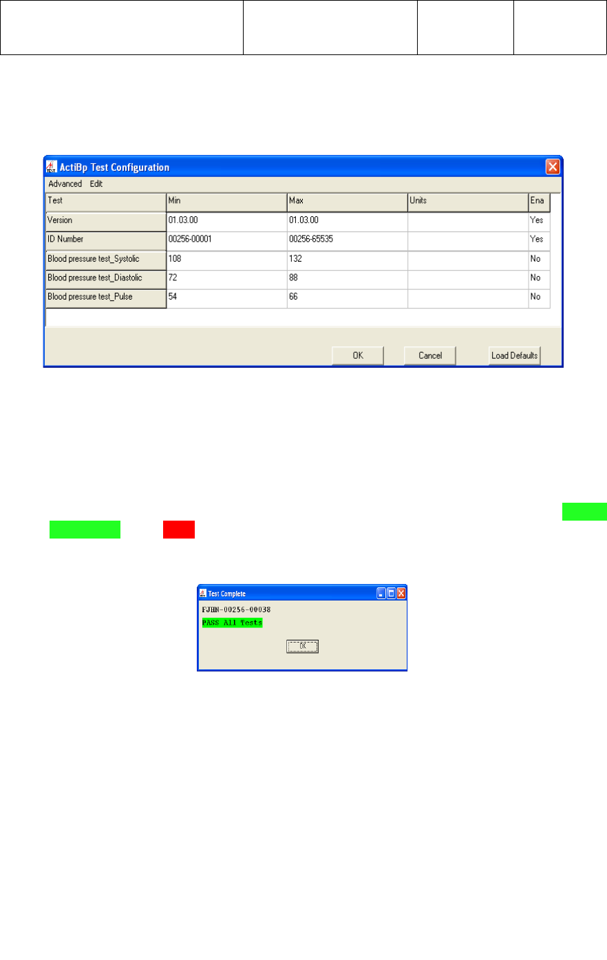
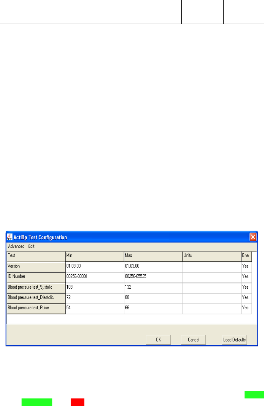
Once in the Test Configuration screen, the test “limits” should be set as follows for
Incoming Test of the UWM PCB;
●Version - Min and Max values should be set to reflect the latest revision of UWM
PCB firmware. The current firmware Version is 1.3.0
●ID Number - Min and Max values should be set to reflect the range of UWM PCB
ID Numbers for the BP monitor. The current ID Number range is from
00256-00001 through 00256-65535.
In the Test Configuration screen, each sub-test can be enabled or disabled as required
by entering Yes or No in the “Ena” column. For Incoming Test of the UWM PCB, the
tests should be enabled/disabled as follows and as shown in the screen capture below.
●Version - Enabled with a Yes in the Ena column.
●ID Number - Enabled with a Yes in the Ena column.
●Blood pressure test_Systolic - Disabled with a No in the Ena column.
●Blood pressure test_Diastolic - Disabled with a No in the Ena column.
SUBJECT:
A&D MEDICAL DIGITAL BLOOD
PRESSURE MONITOR ASSEMBLY
DOCUMENT NUMBER:
910-00059-01
REVISION:
08
PAGE:
6of 18
●Blood pressure test_Pulse - Disabled with a No in the Ena column.
Once the test limits have been correctly set as described above for Incoming Test of
the UWM PCB, select the “OK” tab. This will save the Test Configuration limit settings,
which will now be utilized each time the test application is started.
When the application has completed testing of a UWM PCB, a message with a PASS
ALL Tests or a FAIL status and the ID Number of the tested PCB will be displayed
across the top of the test screen, as shown below.
All results, pass or fail, are captured in a log file located in C:\Program Files\ActiBP
Manufacturing Test folder. The log file will also contain information regarding the Mfg.
Plant and test Station Number. To set the Plant and test Station Number, select
“Edit”, then “Location”, and enter the specific information. Select the “Ok” tab
when complete.
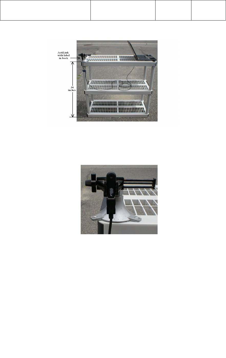
3.3 UWM Incoming Test Setup
A PC or laptop is required for Incoming Test of the UWM PCB. The PC or laptop
should be placed at one end of a non-metallic table top at a height of 36 inches (0.914
meters) from the floor. The ActiLink should be placed on the opposite side of the the
laptop or PC at a height of 36 inches (0.914 meters) from the floor using a USB
extension cable. Refer to photograph below.
SUBJECT:
A&D MEDICAL DIGITAL BLOOD
PRESSURE MONITOR ASSEMBLY
DOCUMENT NUMBER:
910-00059-01
REVISION:
08
PAGE:
7of 18
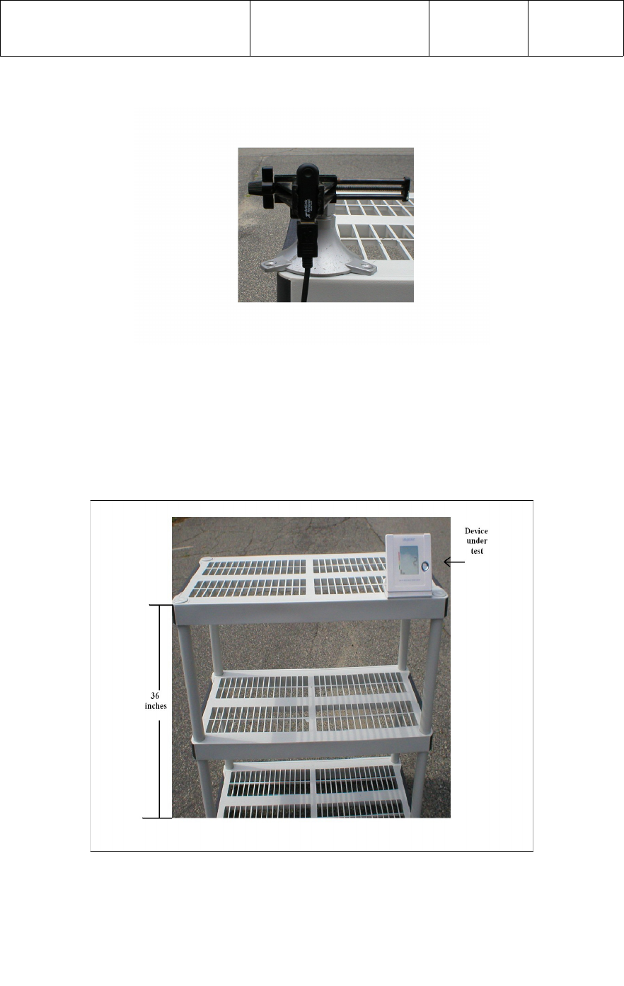
The ActiLink label should be facing opposite the direction of the UWM PCB under test,
as shown in the photograph below.
The Incoming Test fixture containing the UWM PCB under test should be placed at a
distance of 100 feet (30.5 meters) at one end of a non-metallic table top, at a height of
36 inches (0.914 meters) off the floor, with the tip of the antenna facing the ActiLink.
Refer to the photograph below.

SUBJECT:
A&D MEDICAL DIGITAL BLOOD
PRESSURE MONITOR ASSEMBLY
DOCUMENT NUMBER:
910-00059-01
REVISION:
08
PAGE:
8of 18
All wireless devices should be removed from the test area, and the PC or laptop
wireless capability should be turned off or disabled.
No obstacles should be between the ActiLink and the UWM PCB under test.
3.4 UWM Incoming Test Process
The following test process can be used to verify the UWM PCB functionality prior to
being reworked into Digital Blood Pressure Monitor.
With an ActiLink installed in the PCs USB port, start the ActiBPMfgTest.exe test
application from the shortcut on the desktop and select System Test. The Test
Configuration limits must be set correctly as detailed in Section 3.2
3.4.1 Install the UWM PCB to be tested into the test fixture at the 100 foot (30.5 meters)
distance with the UWM antenna tip facing the ActiLink. Power up the test fixture.
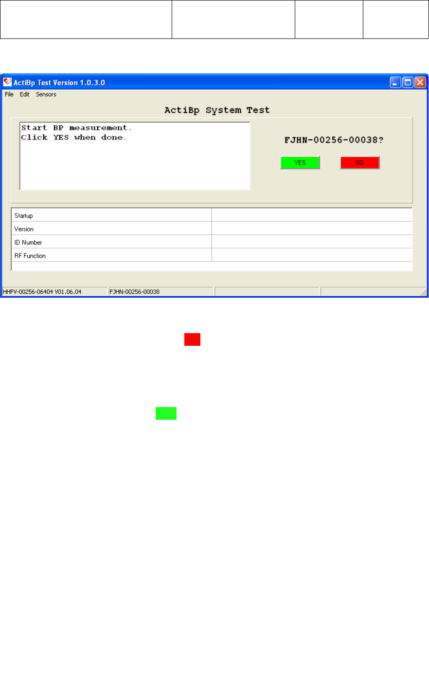
3.4.2 In the upper right corner of the System Test screen above the [YES] [NO] tab, the
ID Number of the UWM PCB to be tested will boldly appear approximately 5 seconds
after power is applied, as shown below for ID Number FJHN-00256-00038.
SUBJECT:
A&D MEDICAL DIGITAL BLOOD
PRESSURE MONITOR ASSEMBLY
DOCUMENT NUMBER:
910-00059-01
REVISION:
08
PAGE:
9of 18
If the ID Number of a UWM PCB other than that to be tested appears in the upper right
of the test screen, selecting the [NO] tab will enable a filter preventing the application
from detecting the unwanted sensor. This allows the operator to filter out all other
UWM PCBs other than the specific UWM to be tested. To enable the application to
detect all UWMs again, select the “Sensors” tab, then “Clear Reject List”.
3.4.3 With the ID Number of the UWM PCB under test boldly displayed on the screen, the
operator would select the [YES] tab to start the test.
The application will now perform the following 4 sub-tests;
●Startup
This test verifies that the application has RF communication with the UWM PCB
prior to starting the test.
●Version
This test verifies the UWM PCB has the correct firmware Version as defined in the
Min and Max test “Limits”.
●ID Number
This test verifies the Serial Number or ID Number of the UWM PCB is within the
specified range as defined in the Min and Max test “Limits”. The operator should
verify that the ID Number label on the UWM PCB matches the device being tested
by the application.
●RF Function
This test verifies the RF transmit and receive function of the UWM PCB.

SUBJECT:
A&D MEDICAL DIGITAL BLOOD
PRESSURE MONITOR ASSEMBLY
DOCUMENT NUMBER:
910-00059-01
REVISION:
08
PAGE:
10of 18
3.4.4 Once all 4 sub-test have completed, a status message of PASS ALL Tests or
FAIL, and the ID Number of the UWM PCB that was tested will be displayed across
the top of the test screen as shown below for ID Number FJHN-00256-00038.
3.4.5 The operator should verify that the Device ID displayed by the test application, and
the labels on the UWM PCB and contained in the ESD bubble bag, all match.
3.4.6 Using a digital multimeter, verify the CR1225 lithium battery on side 2 of the UWM
PCB measures between 3.00 to 3.30vdc. Do not remove the battery to perform this
test.
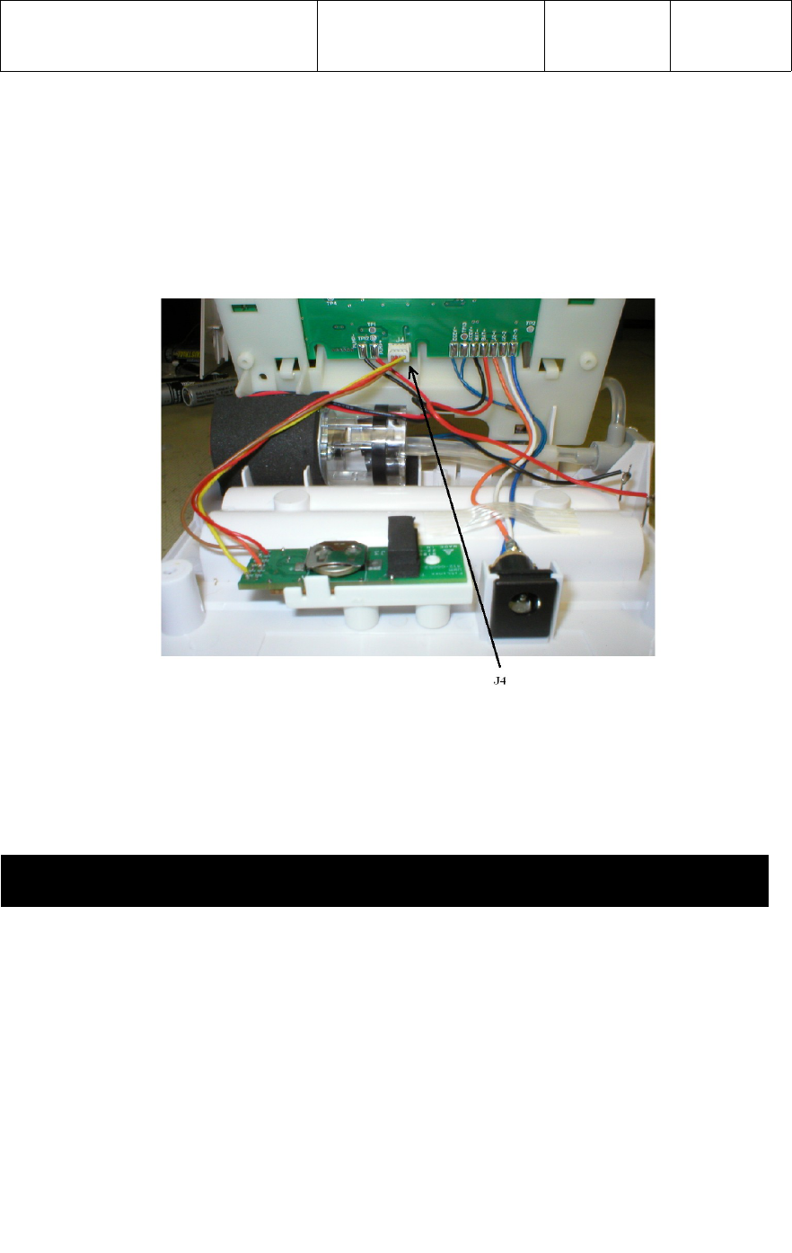
4 BP MONITOR REWORK INSTRUCTIONS
The UWM PCB is integrated into the BP monitor using four (4) 30AWG (7/38)
stranded wires at specific lengths to accommodate the proposed mounting of the
UWM PCB with the connection to the BP monitor PCB at connector J4 as shown in
the photograph below.
Four (4) test points on the UWM PCB connector J1 are wired to the four pins of J4 on
the BP monitor PCB as follows;
UWM PCB Signal Name Wire Color BP Monitor PCB
J1 – 1 (V) 3.30vdc Brown J4 - 1
J1 – 2 (G) Ground Red J4 - 2
J1 – 8 (RX) UART RX Data Orange J4 - 3
J1 – 11 (P00) Wakeup Yellow J4 - 4
4.1 Install the UWM PCB into the clip and install in base with compression foam as shown
in photograph below.
4.2 Plug J4 connector from the UWM PCB into the BP monitor PCB as shown in
photograph below.
SUBJECT:
A&D MEDICAL DIGITAL BLOOD
PRESSURE MONITOR ASSEMBLY
DOCUMENT NUMBER:
910-00059-01
REVISION:
08
PAGE:
11of 18
4.3 Assemble BP monitor per manufacturing assembly process.
4.4 Clean the location for the ID Number and FCC label with 90% Isopropyl Alcohol
and allow to dry. Place labels per the manufacturing assembly process.
4.5 Test the functionality of the BP monitor per Section 5 of this document.
5 FUNCTIONAL TEST
5.1 Test Equipment
The following test equipment is required to test the wireless blood pressure monitor.
●A USB based Personal Computer with Windows XP/2000 O.S. (provided by A & D
Medical).
●A known Blood Pressure Systolic, Diastolic, and pulse
●A know good ActiLink (provided by FitSense)
●ActiBP Manufacturing Test application (provided by FitSense)
●Faraday cage (if required by manufacturing)
5.2 ActiBP Manufacturing Test application
SUBJECT:
A&D MEDICAL DIGITAL BLOOD
PRESSURE MONITOR ASSEMBLY
DOCUMENT NUMBER:
910-00059-01
REVISION:
08
PAGE:
12of 18
The System Test portion of the ActiBPMfgTest Manufacturing Test application
should be used for Incoming Test of the wireless BP monitor. When the application is
started, Select the tab for System Test.
The application (ActiBPMfgTest.exe) is installed in the C:\Program Files\ActiBP
Manufacturing Test. The application can be setup as a shortcut on the desktop.
A known good ActiLink must be installed in the USB port of the test PC prior to starting
the application. If no ActiLink is present, or the ActiLink is not functioning properly, an
error message “Check Link Connection, Program will close” will be displayed
and the program will exit when the operator clicks on the “OK” tab as shown below.
The application has a Test Configuration screen which allows manufacturing engineers
to enable/disable tests and set specific test parameters. Test Configuration limits that
can be modified include Blood pressure test_Systolic, Blood pressure
test_Diastolic, Blood pressure test_Pulse, Version, and ID Number. To access
the Test Configuration screen, the engineer would select “Edit”, then “Limits”,
then enter the password.
No password is set when the application is first installed. Select “OK” to access the
Test Configuration limits screen for the first time. To setup a password, select
“Edit”, then “Limits”. Select “Advanced”, then select “Password”. Enter the new
password and select “OK”. The new password is now required each time to access
the Test Configuration screen.
Once in the Test Configuration screen, the limits should be set as follows for
Functional Test of the wireless Digital Blood Pressure Monitor;
●Version - Min and Max values should be set to reflect the latest revision of UWM
PCB firmware. The current firmware Version is 1.3.0
●ID Number - Min and Max values should be set to reflect the range of UWM PCB
ID Numbers for the BP monitor. The current ID Number range is from
00256-00001 through 00256-65535.
● Blood pressure test_Systolic – Min and Max values should be set to plus/minus
10 percent of the Systolic value being used by manufacturing to test the BP
Monitor. At the time this document was created, the value of 120 was used.
SUBJECT:
A&D MEDICAL DIGITAL BLOOD
PRESSURE MONITOR ASSEMBLY
DOCUMENT NUMBER:
910-00059-01
REVISION:
08
PAGE:
13of 18
●Blood pressure test_Diastolic - Min and Max values should be set to
plus/minus 10 percent of the Dastolic value being used by manufacturing to test
the BP Monitor. At the time this document was created, the value of 80 was used.
●Blood pressure test_Pulse - Min and Max values should be set to plus/minus 10
percent of the Pulse value being used by manufacturing to test the BP Monitor. At
the time this document was created, the value of 60 was used.
In the Test Configuration screen, each sub-test can be enabled or disabled as required
by entering Yes or No in the “Ena” column. For Functional Testing of the BP
monitor, the tests should be enabled/disabled as follows and as shown in the screen
capture below.
●Version - Enabled with a Yes in the Ena column.
●ID Number - Enabled with a Yes in the Ena column.
●Blood pressure test_Systolic - Enabled with a Yes in the Ena column.
●Blood pressure test_Diastolic - Enabled with a Yes in the Ena column.
●Blood pressure test_Pulse - Enabled with a Yes in the Ena column.
Once the test limits have been correctly set as described above for Functional Testing
of the BP monitor, select the “OK” tab. This will save the Test Configuration limit
settings, which will now be utilized each time the test application is started.
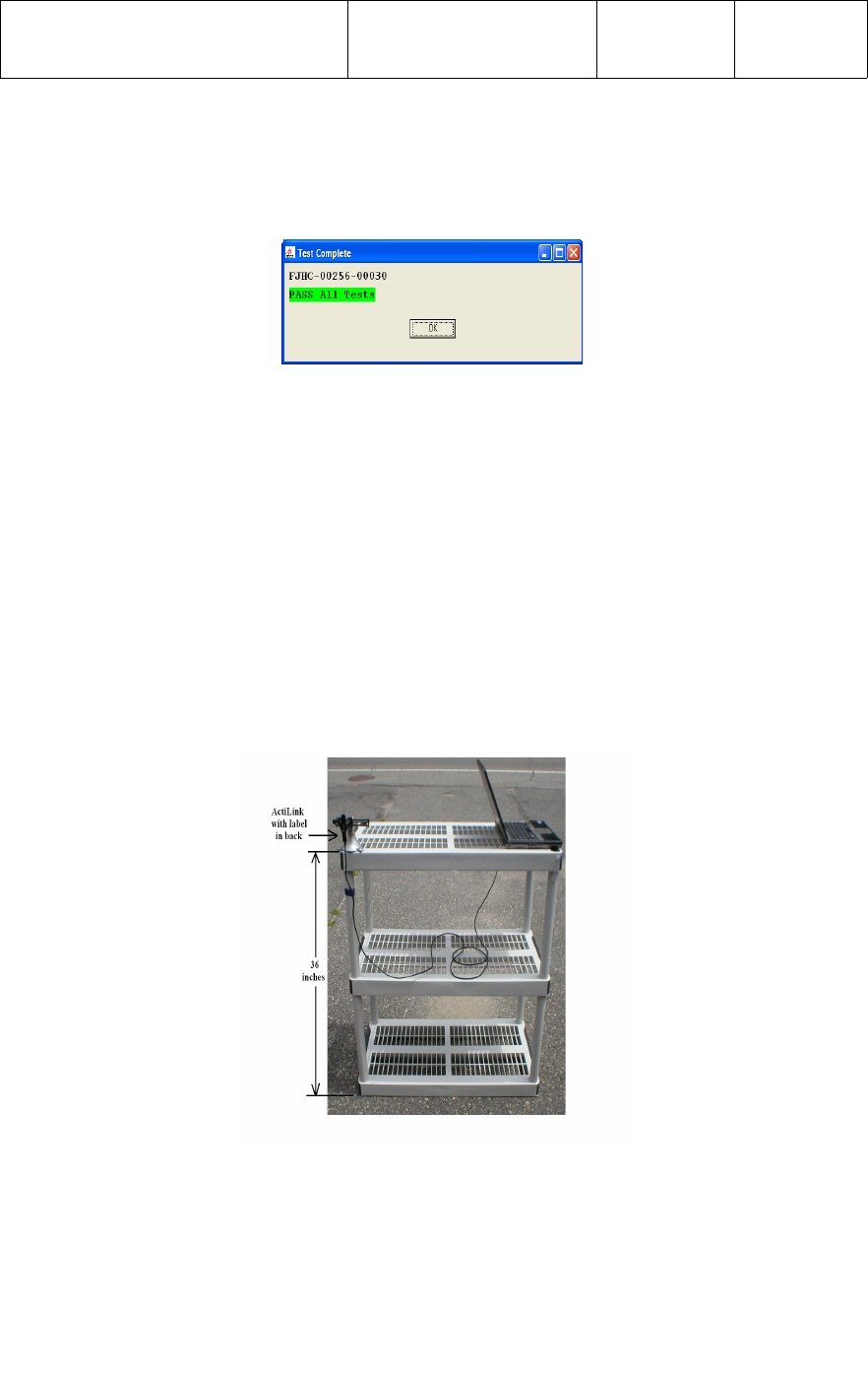
When the application has completed testing the BP monitor, a message with a PASS
ALL Tests or a FAIL status and the ID Number of the BP monitor under test will be
SUBJECT:
A&D MEDICAL DIGITAL BLOOD
PRESSURE MONITOR ASSEMBLY
DOCUMENT NUMBER:
910-00059-01
REVISION:
08
PAGE:
14of 18
displayed across the top of the test screen, as shown below for ID Number FJHC-
00256-00030.
All results, pass or fail, are captured in a log file located in C:\Program Files\ActiBP
Manufacturing Test folder. The log file will also contain information regarding the Mfg.
Plant and test Station Number. To set the Plant and test Station Number, select
“Edit”, then “Location”, and enter the specific information. Select the “Ok” tab when
complete.
5.3 Test Setup
A PC or laptop is required for Functional Testing of the wireless Digital Blood Pressure
Monitor. The PC or laptop should be placed at one end of a non-metallic table top at a
height of 36 inches (0.914 meters) from the floor. The ActiLink should be placed
on the opposite side of the the laptop or PC at a height of 36 inches (0.914 meters)
from the floor using a USB extension cable. Refer to photograph below.
The ActiLink should be orientated such that, the Serial Number label is facing the
opposite direction of the BP monitor under test, as shown in the photograph below.
SUBJECT:
A&D MEDICAL DIGITAL BLOOD
PRESSURE MONITOR ASSEMBLY
DOCUMENT NUMBER:
910-00059-01
REVISION:
08
PAGE:
15of 18
The BP monitor under test should be placed at a distance of 100 feet (30.5 meters) at
one end of a non-metallic table top, at a height of 36 (0.914 meters) inches off the
floor, and with the front of the BP monitor facing the ActiLink. Refer to the photograph
below.
All wireless devices should be removed from the test area, and the PC or laptop
wireless capability should be turned off or disabled.
No obstacles should be between the ActiLink and the BP monitor under test.
SUBJECT:
A&D MEDICAL DIGITAL BLOOD
PRESSURE MONITOR ASSEMBLY
DOCUMENT NUMBER:
910-00059-01
REVISION:
08
PAGE:
16of 18
5.4 Functional Test Process
Two (2) operators are required to Functionally Test the BP monitor at a distance of
100 ft (30.50 meters). The first operator will control the test application on the laptop
or PC. The second operator will operate the BP monitor.
With an ActiLink installed in the PCs USB port, start the ActiBPMfgTest.exe test
application from the shortcut on the desktop and select System Test. The Test
Configuration limits must be set correctly as described in Section 5.2
The following test process should be used to verify functionality of the BP monitor.
5.4.1 The operator will activate the BP monitor and allow it to complete the measurement as
indicated on the LCD display. With the results on the LCD display of the BP monitor,
the operator should walk to a distance of at least 10 feet to the side or rear of the
monitor to prevent interfering with the RF test.
NOTE
Once the BP Monitor is powered up and activated, the operators have
approximately 60 seconds to complete the test before the monitor enters a low
power sleep mode.
5.4.2 The PC operator will then watch the upper right of the System Test screen, just above
the [YES] [NO] tab, for the ID Number of the BP monitor under test to boldly appear as
shown in the screen capture below for ID Number FJHN-00256-00038. This will take
approximately 5 seconds after the BP monitor has been activated.

SUBJECT:
A&D MEDICAL DIGITAL BLOOD
PRESSURE MONITOR ASSEMBLY
DOCUMENT NUMBER:
910-00059-01
REVISION:
08
PAGE:
17of 18
If the ID Number of any BP monitor other than that to be tested is displayed by the
application, the operator selects the [NO] tab for each device detected until the UUT
is detected. The [NO] tab will place the ID Number in a reject list, and the rejected
device will not be displayed again by the application until the operator selects
“Sensors”, then selects “Clear Rejected List”.
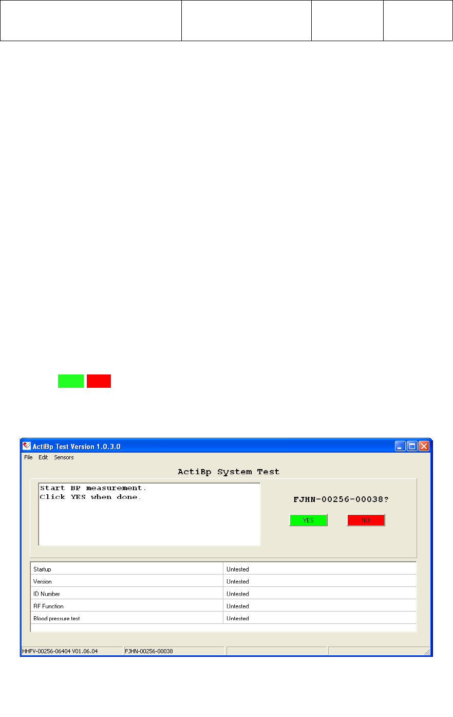
5.4.3 With the blood pressure results displayed on the LCD display of the BP monitor, the
PC operator then starts the test as instructed on the test screen by selecting the
[YES] tab.
Start BP measurement.
Click YES when done.
The application will now perform the following 7 sub-tests;
●Startup
This test verifies that the application has RF communication with the under test
prior to starting the test.
●Version
This test verifies the UWM PCB in the has the correct firmware Version as defined
in the Test Configuration Version limits.
●ID Number
This test verifies the ID Number of the UWM PCB in the is within the specified
range as defined in the Test Configuration Min and Max ID Number limits. The
operator should verify that the ID Number label on the matches the device being
tested by the application.
●RF Function
This test verifies the RF transmit and receive function of the UWM PCB.
●Blood pressure test_Systolic
This test verify the UWM PCB was wired to the proper test point on the BP monitor,
and that the UWM can RF transmit the value display on the BP monitor, to the test
application.
●Blood pressure test_Diastolic
This test verify the UWM PCB was wired to the proper test point on the BP monitor,
and that the UWM can RF transmit the value display on the BP monitor, to the test
application.
●Blood pressure test_Pulse
This test verify the UWM PCB was wired to the proper test point on the BP monitor,
and that the UWM can RF transmit the value display on the BP monitor, to the test
application.

SUBJECT:
A&D MEDICAL DIGITAL BLOOD
PRESSURE MONITOR ASSEMBLY
DOCUMENT NUMBER:
910-00059-01
REVISION:
08
PAGE:
18of 18
5.4.4 Once all 7 sub-test have completed, a status message of PASS ALL Tests or
FAIL, and the ID Number of the BP monitor tested will be displayed across the top of
the test screen as shown below.
6 PACKAGING
Packaging of the A&D Medical Wireless Digital Blood Pressure Monitor is TBD.