FlightScope SS661 Doppler microwave sensor for golf ball launch/flight and golf club head trajectory measurement User Manual
FlightScope (Pty) Ltd Doppler microwave sensor for golf ball launch/flight and golf club head trajectory measurement
User Manual

Rhein Tech Laboratories, Inc. Client: EDH (South Africa) (Pty) Ltd
360 Herndon Parkway Model: FlightScope X1
Suite 1400 Standards: FCC 15.245/IC RSS-210
Herndon, VA 20170 FCC/IC ID: QXP-SS661/4612A-SS661
http://www.rheintech.com Report #: 2013032
Page 27 of 33
Appendix K: Manual
Please refer to the following pages.
Doc No. E19-V9365- Issue 2
COPYRIGHT NOTICE:
The information presented in this document may not be copied or reproduced in any form
whatsoever without the prior written consent of EDH. EDH reserves all rights to the information
published this document. Title of the information and any copies thereof shall remain the property of
EDH. No proprietary, copyright, confidential, or other proprietary rights, legend or markings may be
removed from any part of this document.
3D Golf Ball and Club Monitor

FlightScope X1 User Manual
Copyright EDH 2007-2011 E19-V9365 Issue 2
Page i
GENERAL AND SAFETY NOTICES
Summary
The following notices and general safety precautions must be observed during the
operation, service and repair of this equipment. Failure to comply with these precautions
or with warnings elsewhere in the manual violates standards of the design, manufacture
and intended use of the equipment. EDH accepts no liability for failure to comply with
these notices.
Operation of the device in any country may require approval in accordance
with local telecommunications and safety regulations.
Sheltered and Clear Weather Use Only
The equipment has been designed for sheltered or in clear weather use and must not be
used outdoors under rainy conditions.
FCC Statement
Changes or modifications not expressly approved by EDH (South Africa) (Pty) Ltd
could void the user's authority to operate the equipment.
This equipment has been tested and found to comply with the limits for a Class B digital
device, pursuant to part 15 of the FCC rules. These limits are designed to provide
reasonable protection against harmful interference in an office or residential installation.
This equipment generate, uses and can radiate radio frequency energy and, if not
installed and used in accordance with the instructions, may cause harmful interference
to radio communications. However, there is no guarantee that interference will not occur
in a particular installation. If this equipment does cause harmful interference to other
electronic equipment, which can be determined by turning this equipment off and on,
the user is encouraged to try to correct the interference by one or more of the following
measures:
Increase the separation between the equipment causing and experiencing the
interference
Install a radio frequency shield between the equipment causing and experiencing the
interference
Consult your dealer for help
This device complies with Part 15 of the FCC Rules. Operation is subject to the following
two conditions:
This device may not cause harmful interference.
This device must accept any interference received, including interference that may cause
undesired operation.

FlightScope X1 User Manual
E19-V9365 Issue 2 Copyright EDH 2007-2011
Page ii
IC Statement
This device complies with Industry Canada license-exempt RSS standard(s). Operation is
subject to the following two conditions: (1) this device may not cause interference, and
(2) this device must accept any interference, including interference that may cause
undesired operation of the device.
Déclaration IC
Le présent appareil est conforme aux CNR d'Industrie Canada applicables aux appareils
radio exempts de licence. L'exploitation est autorisée aux deux conditions suivantes : (1)
l'appareil ne doit pas produire de brouillage, et (2) l'utilisateur de l'appareil doit accepter
tout brouillage radioélectrique subi, même si le brouillage est susceptible d'en
compromettre le fonctionnement.

FlightScope X1 User Manual
Copyright EDH 2007-2011 E19-V9365 Issue 2
Page iii
Table of Contents
Introduction .............................................................................................. 1
Getting Started - Installation ...................................................................... 3
System Components ............................................................................... 3
Hooking up the cables ............................................................................... 4
USB Cable Connection ......................................................................... 4
Power Supply Connection .................................................................... 4
Placing the Sensor ..................................................................................... 5
Setting up the sensor ................................................................................. 6
Position .............................................................................................. 6
Ground Surface................................................................................... 6
Handle ............................................................................................... 6
Leveling the sensor ............................................................................. 6
Switching On and Off ............................................................................. 7
Switching On ...................................................................................... 7
Switching Off ...................................................................................... 7
Setup Wizard ......................................................................................... 9
Step-by-step procedure ....................................................................... 9
Spin Measurement ................................................................................... 12
Spin measurement methods ............................................................... 12
Spin Measurement ................................................................................... 13
Spin measurement methods ............................................................... 13
Marking and placing a ball for spin measurement ................................. 13
Spin measurement rule: .................................................................... 13
Sensor Status Indicators .......................................................................... 15
Battery Level ........................................ Error! Bookmark not defined.
Sensor Status ................................................................................... 15
Tooltips ............................................................................................ 15
Club Type and Roll/Tilt indicator ......................................................... 15
Sensor Firmware Updating ....................................................................... 17

FlightScope X1 User Manual
E19-V9365 Issue 2 Copyright EDH 2007-2011
Page iv
Technical Capabilities ............................................................................... 21
Balls and Clubs ................................................................................. 21
Measurement zone ............................................................................ 21
Launch velocity ................................................................................. 21
Launch angles ................................................................................... 21
Carry and lateral distances ................................................................. 21
Trajectory height............................................................................... 21
Club head Speed ............................................................................... 21
Spin ................................................................................................. 21
Physical Characteristics ............................................................................ 22
Dimensions (approximate) ................................................................. 22
Mass (sensor) ................................................................................... 22
Environmental Specifications ..................................................................... 22
Ambient temperature: ....................................................................... 22
Ingress protection: ............................................................................ 22
Electrical Characteristics ........................................................................... 22
PC / Mobile Specifications ......................................................................... 23
PCs and Notebooks ........................................................................... 23
Electrical Power Requirements .................................................................. 23
Locations .......................................................................................... 23
Supply Voltage .................................................................................. 23
Earthing ........................................................................................... 23
Requirements for Outdoor Installations ...................................................... 23
Maintenance and Troubleshooting ............................................................. 25
Basic Care ........................................................................................... 25
Rear Panel LED Indicator .......................................................................... 27
Frequently Asked Questions (FAQ) ............................................................ 29
Index ..................................................................................................... 33

I
NTRODUCTION
Congratulations on purchasing FlightScope
®
, the world’s first-ever 3D
Doppler tracking system for golf.
FlightScope measures how a player hits golf balls, providing information
about the player and the equipment (clubs and balls).
Here are a few examples of what FlightScope can do:
Test clubs and balls to find the best equipment for a player
Measure performance of a player
Golf instruction
Calibrate golf clubs in a player’s bag
Compare performance with other players including top golfers
Evaluate personal progress
Provide instructional and entertaining data about golf shots not known to
most golfers
Research on club and ball performance
As a professional club fitter or golf instructor you can measure the
performance and progress of a player and his/her equipment accurately and
scientifically, find the best equipment fit, and evaluate progress.
As a player, you will be able to go out onto the course knowing your yardage
and shot making capabilities. This will improve your scores and enjoyment of
the game.

Blank Page

G
ETTING
S
TARTED
-
I
NSTALLATION
Before FlightScope can be used, the sensor and other hardware and software
must be installed.
System Components
Your X1 system needs a PC/Notebook computer to install and use
FlightScope.
The components included with your system are:
Sensor Unit
USB Cable
AC Adapter
Mains Power Cord
Software on CD
User Manual
Carry Case
The system is intended for use with a PC or notebook computer. See section
on Error! Reference source not found. for details of compatible devices.
H
OOKING UP THE CABLES
CAUTION
Ensure that connectors are inserted with the
correct orientation.
The connectors are keyed to ensure that they are
inserted correctly. Do not force the connectors
when inserting.
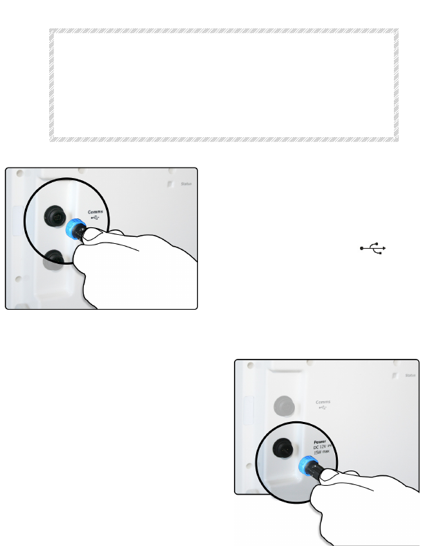
USB Cable Connection
Insert the Communications Cable
(USB) to your PC and connect the
other end to the COMMS connector
marked with the symbol - .
Insert the connector and fasten the
nut lightly.
Power Supply Connection
Insert the AC Adapter connector
into the Power connector on the
rear of the sensor.
The connector is keyed and can
only be inserted one way.
Insert the connector and fasten
the nut lightly.
P
LACING THE
S
ENSOR
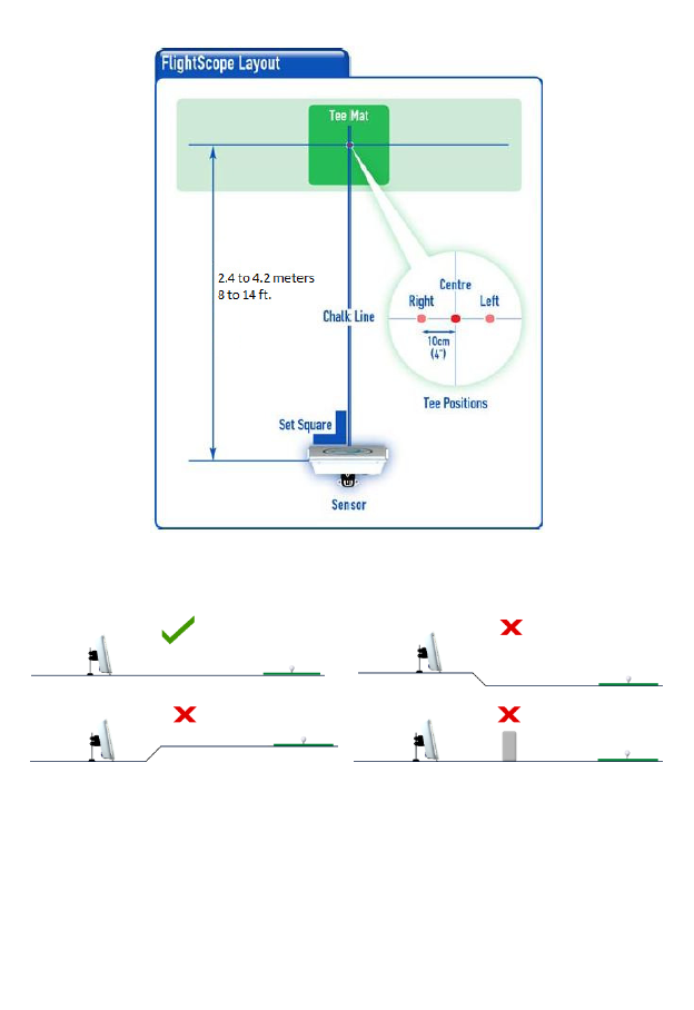
NOTE
Use FlightScope on a level surface. There must
be no obstructions in front of the sensor.

S
ETTING UP THE SENSOR
Position
The sensor must be placed between 2.4 to 4 meters (8 to 14 ft.) behind the
tee.
Ground Surface
The sensor should be used on a level surface, (grass, carpet, or hard floor).
Handle
CAUTION
The handle is locked in position by spring loaded
plungers. Release the plungers before moving the
handle. Do not force the handle while locked.
Release the handle by sliding the two lock catches inwards to release the
spring loaded pins that lock the handle position. At the same time pull the
handle backwards.
When free, move the handle to the “down” position. The spring loaded pins
will again lock the handle in the down position.
In the down position, the handle acts as the rear support for the sensor.
Leveling the sensor
The sensor should be set up with no roll (sideways angle) and tilted at the
optimum angle of approximately 10 degrees (leaning backwards).
The sensor roll and tilt angles must be manually set by adjusting the feet of
the sensor and/or by modifying the work surface to achieve the correct
sensor angles.

Switching On and Off
Switching On
The FlightScope X1 has no On/Off switch.
It will start up when it is connected to a power supply.
The system is powered by the supplied AC adapter, which in turn must be
connected to an AC supply (100-240 V AC single phase).
When on, the Status LED indicator lamp will light up and blink. See LED
Indicator states below.
Switching Off
The FlightScope X1 has no On/Off switch.
Simply switch off the power supply or disconnect the power cable from the
sensor.

Blank Page
Setup Wizard
NOTE
Do set-up at least the first time the
system is used.
The Setup Wizard is a step-by-step procedure to be followed before using the
FlightScope. It can be skipped if the set-up remains unchanged between use,
but should be repeated if the set-up changes (e.g. if the system is moved to
a different location).
The Setup Wizard can be started from the Main screen menu or from the
Advanced Settings (F10) menu.
Step-by-step procedure
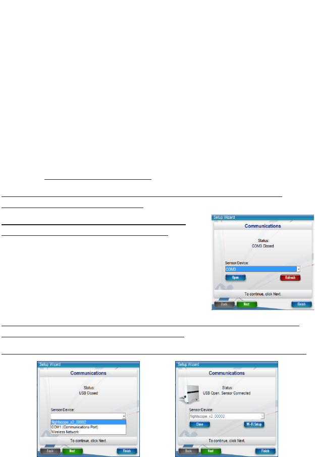
Setup 1. Connection (by USB cable)
Connect the sensor to the PC and turn power on. Run the FlightScope
software and choose Setup Wizard.
On the Communications screen (right) choose
Refresh to list the available connections.
Open the list of Sensor Devices and select the indicated FlightScope in the
list (see example below). Then click “Open”.
The sensor will now connect and showing the selected COM port as “Open”.
Click “Next” to continue to sensor mode and geometry, or “Finish” to exit
Setup Wizard.
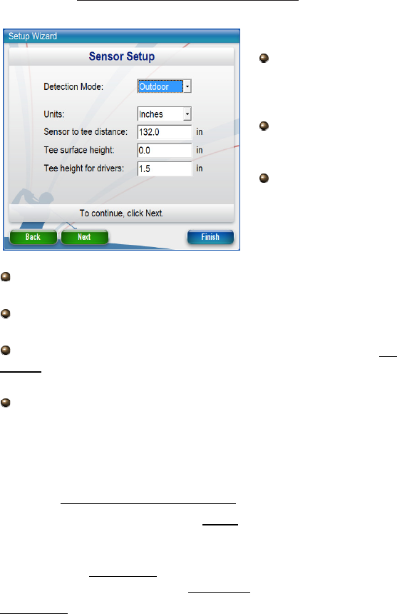
Setup 2. Set up the sensor mode and geometry.
Set the Detection Mode:
Select Indoor if the
system is used indoors e.g.
in a hitting cage with
limited ball travel distance.
Select Outdoor if hitting
outdoors e.g. on a driving
range or golf course.
Select Long Indoor to use
when the ball travel
distance is more than 20
yards/meters but full ball
flight is not possible (e.g.
there is a distant net
Choose the Units to use for entering for the hitting geometry
(Inches or Centimeters).
Enter the Sensor to Tee distance, which is from the tee/hitting
spot to the sensor face.
Enter the Tee surface height which is the height of the tee
surface (
not the Ball Tee itself
) above the surface on which the FlightScope is
placed.
Enter the Tee Height for Drivers. This value is the height of a tee
above the Tee surface when using a Driver. For other clubs, this height is
assumed to be 0 (zero).
Click “Next” to continue.
Setup 3. Tilt, Roll and Pointing Direction
NOTE
FlightScope X2C models have automatic tilt and
roll adjustment. If you use this model, skip the
Tilt and Roll adjustment below and proceed to
the Ball Origin step
Tilt and Roll
The wizard indicates the sensor’s actual roll and tilt angles. Ideal Roll is
between +0.3 and -0.3 degrees and Tilt between 9.5 and 13 degrees. If
needed, adjust the sensor feet to correct the roll and tilt angles.
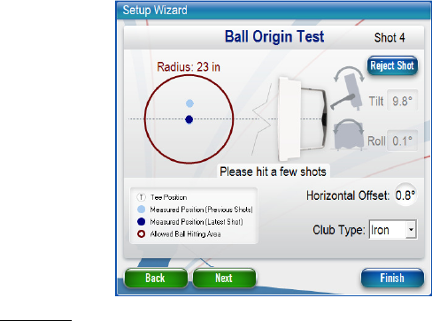
Ball Origin
The purpose of this step is to point the sensor through the tee position along
a desired target line. The target line could for example be to a distant flag or
feature on a driving range, or to the center of an indoor hitting cage net.
To use the wizard, select a club type to use for the test (iron, driver or
wedge) and proceed to hit one or more balls from the chosen tee position.
The ball origin for each shot is displayed as a blue dot. The latest shot will be
dark and previous shots are a lighter shade. The ball origins will typically be
spread around center of the red circle if the sensor pointing direction is more
or less correct. The dots can be closely spaced and should overlap. Any
outlier shot can be rejected (“Reject Shot”).
The average “Horizontal Offset” for the played shots is displayed. This should
be 0 (zero). If the error is not close to 0, correct the pointing direction by
slight clockwise or counterclockwise rotation of the sensor, and repeat the
Ball Origin test.
NOTE
The horizontal error must as small as
possible. A Horizontal Offset of 1˚
translates to a lateral error of 2.5 yards at
a distance of 150 yards.
The “Ball Origin” can also be checked at any time during system operation
from the Advanced Settings menu (F10 > Sensor > Ball Origin).
Click “Next” to continue.
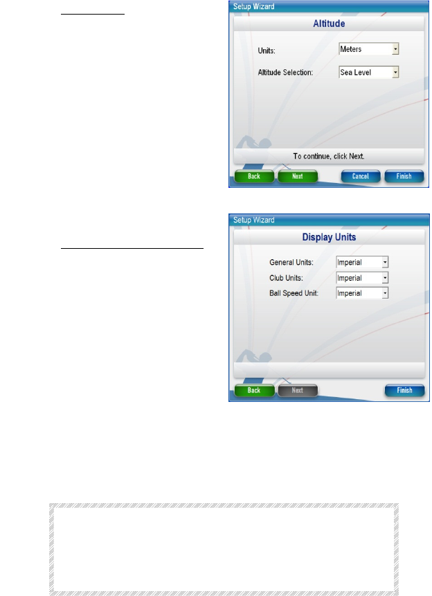
Setup 4. Set Altitude
Set the altitude (meters or feet) as
Sea Level, Medium, High or a
Custom value.
The Altitude setting is important when
Indoor or Long Indoor modes are
used, as this affects the calculation of
ball flight from the initial trajectory
Click “Next” to continue.
Setup 5. Set Units of Measurement
Set the units of measurement for data
(Metric or Imperial).
To complete the setup, press Finish.
.
The system is now ready for use.
S
PIN
M
EASUREMENT
FlightScope measures the spin of a ball accurately both outdoors as well
indoors where ball flight distance/time is limited.
CAUTION
Balls in poor condition or of poor quality (for
example damaged balls) should not be used when
measuring spin because the marks on the ball may
cause incorrect spin to be reported.
Spin measurement methods
FlightScope directly measures the spin rate of the ball both indoors and
outdoors.
S
PIN
M
EASUREMENT
FlightScope measures the spin of a ball accurately both outdoors as well
indoors where ball flight distance/time is limited.
CAUTION
Balls in poor condition or of poor quality (for
example damaged balls) should not be used
when measuring spin because the marks on
the ball may cause incorrect spin to be
reported.
Spin measurement methods
FlightScope directly measures the spin rate of the ball both indoors and
outdoors.
Marking and placing a ball for spin measurement
NOTE
This procedure is only required when
measuring spin indoors.
A ball flight distance of at least 14 ft. (4.2 meters) is necessary.
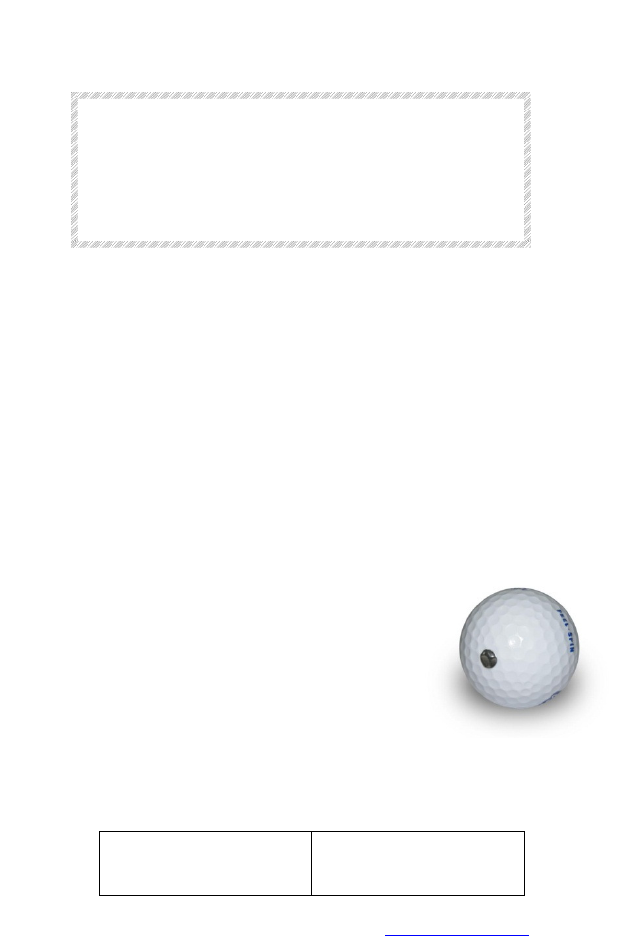
A metal foil disk or patch is used to assist FlightScope to detect the spin of
the ball reliably in a hitting cage where the flight time is limited:
i. Stick a single metal foil disk or patch of
approximately 5mm (1/4 inch)
diameter/dimensions to the surface of
the golf ball.
ii. Tee the ball up with the metal disk
facing forward, away from the sensor.
Spin measurement rule:
Outdoors
Indoors
Use unmarked balls in
good condition
Use with balls marked
with metal sticker
Metal sticker order info: Part# 77715A33 Foil from www.mcmaster.com

Blank Page
S
ENSOR
S
TATUS
I
NDICATORS
Various system status and controls are displayed in the upper right hand
corner of the screen.
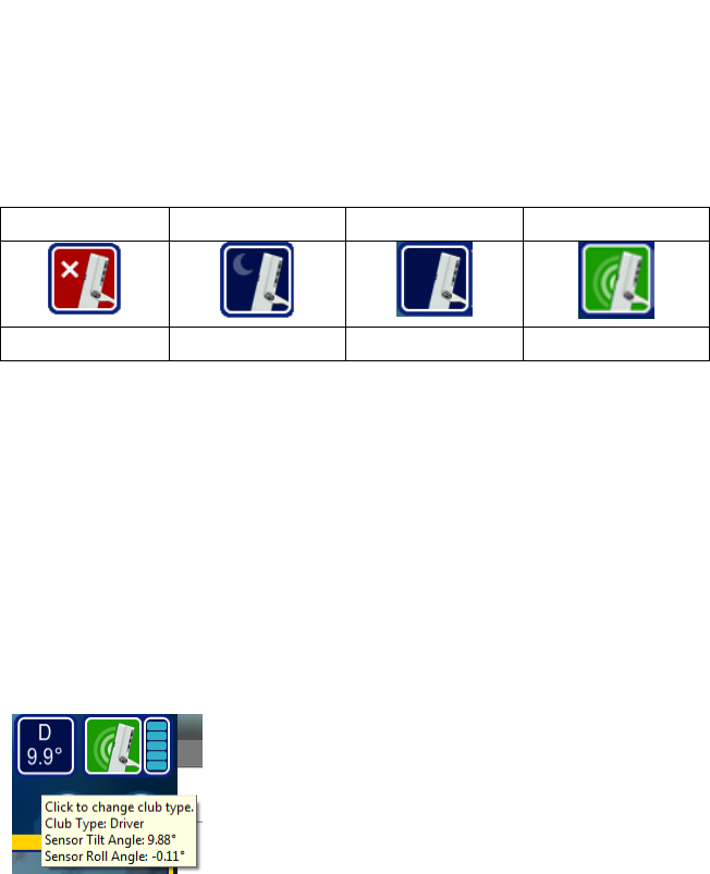
Sensor Status
Sensor status is displayed as follows:
Disconnected Sleeping Standby Active
The indicator will show Disconnected (red) when the sensor is not connected
(by either USB cable or Wi-Fi or if the sensor is not switched on. If this
occurs (a) check that the sensor has power and is switched on (b) check that
the USB cable is connected to the PC OR that it is connected by Wi-Fi. Then
run the Setup Wizard, Refresh connections list, and Open the correct USB or
Wireless connection.
Tooltips
Place/Hover the mouse over any of the sensor status indicators to see a
short description of the indicator.
Club Type and Roll/Tilt indicator
Click this indicator to set the club (D: Driver, I: Iron
or W: Wedge) you are using.
The indicator also displays the sensor’s tilt and roll angles. The user is
warned when the sensor is not in ideal tilt range or roll range.
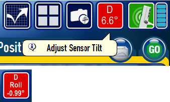
When the roll angle is within
acceptable limits, only the tilt
angle is displayed.
If the Roll Angle is outside the
ideal range, the icon will
indicate a Roll warning
S
ENSOR
F
IRMWARE
U
PDATING
This section describes the procedures to update Sensor firmware.
CAUTION
Sensor firmware programming is a critical task
that requires the power supply and USB
connections to be uninterrupted while in
process.
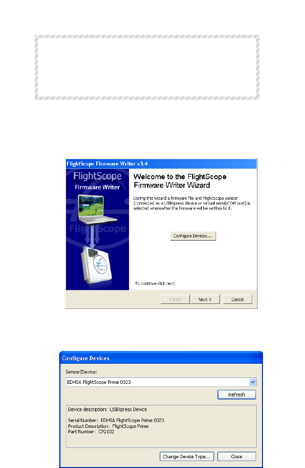
1. With the sensor connected and switched on, open the Firmware Writer
program from the Start Menu.
2. After the application has opened click on Configure Devices on the
welcome screen.
3. Select a sensor from the list (in case more than one sensor is found).
Only one sensor should be connected when programming firmware, so
that a wrong selection is not made.
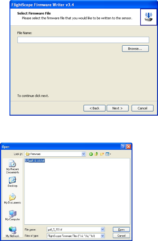
4. Use the Refresh button to update the list if a sensor is removed and re-
connected to the PC. If no sensors are listed after pressing the refresh
button when a sensor is connected then the PC may still be installing
software drivers.
5. On the next screen, click Browse to locate the firmware file.
6. From the open dialog box find and select the golf_6_xx.fsj file and
click on “Open” .The file will normally be located in the Firmware
directory on the CD, or within the program files PC directory:
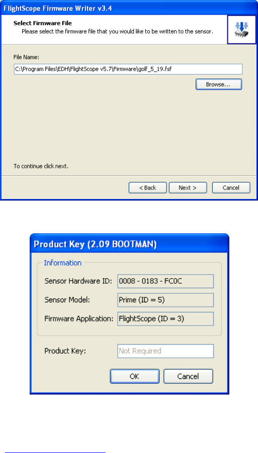
7. Press Next to proceed with the selected firmware file.
8. The Product Key dialog box will pop up and indicate if a product key is
required or not.
9. If the message “Please contact EDH for a product key to run this
firmware”, you will be asked to supply the information provided in the
product key window. Click “OK” and make a note of the information.
This information must be supplied to an EDH support engineer by email
on support@flightscope.com. The product key to enter will be provided
on return. Enter the product key obtained in the Product Key field and
click “Next”.
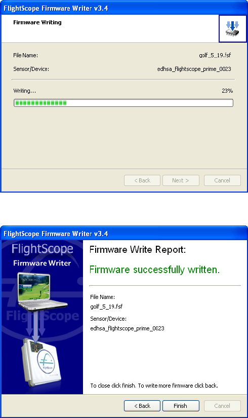
10. The firmware will now be written to the sensor:
11. On completion of writing, cycle the power on the Sensor to reboot, and
then click on Finish.

T
ECHNICAL
C
APABILITIES
Specifications below represent typical performance.
Balls and Clubs
All regulation tournament balls and good quality practice range balls. All
woods, drivers, irons, wedges and hybrids can be measured.
Measurement zone
The sensor measures ball flight in a spatial volume of approximately 20
degrees by 20 degrees around its pointing direction.
Launch velocity
From 2 to 400 km/h (1.2 to 250 mph)
Launch angles
Vertical and horizontal (direction) angles, within the measurement zone.
Carry and lateral distances
Carry and lateral distances refers to the landing position of the ball.
Trajectory height
The height the ball reaches along its flight path.
Club head Speed
The club head strike speed.
Spin
Spin of ball at launch. This spin rate is directly measured and requires the
use of good quality balls. Poor ball quality may affect accurate measurement
of spin rate. The ball must be marked when testing indoors (see section on
“Spin Measurement”).

P
HYSICAL
C
HARACTERISTICS
Dimensions (approximate)
300 x 325 x 100 mm (11
7
/
8
x 12¾ x 4 in) (H x W x D)
Mass (sensor)
3.3 kg (7¾lbs)
E
NVIRONMENTAL
S
PECIFICATIONS
Ambient temperature:
Recommended operating range: 0ºC to 45ºC (32ºF to 104ºF)
Ingress protection:
IP54 / NEMA-4
E
LECTRICAL
C
HARACTERISTICS
Electrical supply: 100-240 V AC @ 0.2 Amp 50/60Hz single
phase
Communications interface: USB 2.0 Hi Speed
Electromagnetic compatibility: Meets FCC Class 15, Industry Canada,
and CE requrements

PC
/
M
OBILE
S
PECIFICATIONS
PCs and Notebooks
Most new PCs or Notebook computers with the following minimum
requirements can be used with FlightScope:
Processor/speed: Any
Memory (RAM): 1 GByte or more recommended
Hard disk storage: 80 GByte or more
CD/DVD ROM drive
Display: 1024 x 768 pixels or more
1
Interface ports: USB 2.0 Hi Speed, DC supply current to 500 mA
2
Operating system: Microsoft Windows XP, Vista, or Windows 7.
1 A sunlight-readable screen is strongly recommended if used outdoors
2 Consult your PC vendor to determine if your computer’s technical specifications meet
the USB port requirements.
E
LECTRICAL
P
OWER
R
EQUIREMENTS
Locations
Mains electrical power supply need to be provided at the following points:
Sensor mounting position
Computer position
Supply Voltage
The sensor supply shall be 100-240VAC, 0.2A. 50/60Hz. Single phase
Earthing
An earth connection must be provided in addition to the live and neutral
circuits.
R
EQUIREMENTS FOR
O
UTDOOR
I
NSTALLATIONS
The following are typical requirements for an outdoors installation:
(Safe) mains power supply point
(100V to 240 V AC, 0.2A, 50/60 Hz, single phase).
Tee on grass or hitting mat.
Level surface
Blank Page

M
AINTENANCE AND
T
ROUBLESHOOTING
FlightScope is designed to operate reliably with a minimum of maintenance
for many years. This section tells you how to care for your FlightScope to
ensure that you achieve this.
Basic Care
1. DIRT AND GREASE: Keep the sensor clean. Clean occasionally with a
damp cloth using a light detergent if necessary. WARNING: As a safety
precaution, always switch electrical supplies off when working or
maintaining electronic equipment.
2. TRANSPORTATION: Place your FlightScope in its original shipping
carton or case, to prevent it from damage when transported in a vehicle
or aircraft. Contact your FlightScope distributor for advice on transport
packaging options in case your original packaging is not available.
3. ALIGNMENT: The alignment of the sensor is important to ensure good
results.
4. AREA: The performance of the system may be affected if used where
the ground of floor is not reasonably level. There must also be no
obstructions between the sensor and the tee.
5. PARAMETERS: Do not change the sensor Parameters that are
accessible under the Advanced Settings menu, unless instructed by a
FlightScope Support engineer. If parameters are changed, the function
and performance of the system may be compromised.
6. RAIN: Although the sensor is sealed and will not allow rain and dust to
enter, the mains power supply connection may be unsafe if wet. When it
rains, switch the system off and take it undercover or cover the sensor
and especially power cables and AC adapter with a waterproof covers as
a precaution.
7. MECHANICAL SHOCK: The sensor contains sensitive microelectronic
circuits that may be damaged or altered by hard impacts. Therefore,
take care not to drop the sensor, hit it with a club or ball, or cause any
other impact to it if possible.
8. CABLE DAMAGE: Check your power supply and communications cables
occasionally for damage or wear. Repair or if necessary replace
damaged or worn cables.
9. CABLE HANDLING: Take care not to pull, twist or kink cables when
handling, to prevent possible damage and ensure long life. When
disconnecting cables, coil the cables loosely before packing.
Replacement cables are available from your FlightScope distributor.
10. SENSOR DAMAGE: Regularly check the sensor for signs of damage. If
enclosure is damaged it can be repaired at a FlightScope service
location.
11. REPAIRS: The sensor contains no user serviceable parts. If necessary
the sensor must be returned to your supplier for repairs. Unauthorized
opening and repair actions may invalidate warranty.
R
EAR
P
ANEL
LED
I
NDICATOR
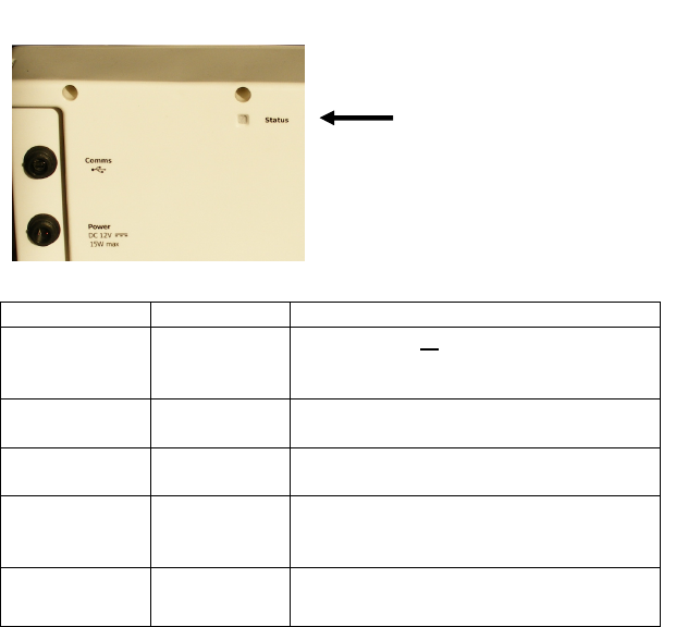
A multi-color LED status
indicator is located on the
rear panel of the sensor.
Colour State Description
None OFF Power is OFF or Sensor defective.
Check power connection/send for
servicing.
Blue Blinking
System
switching on
After switch on
Green
flashing (fast)
Processor
Initialization
System is powered ON and the signal
processor is running normally.
Green
flashing (slow)
Idle System is powered ON and signal
processor is running normally. System
is not armed.
Red/Green
flashing
Armed System is running and ready to
measure a shot.
Blank Page

F
REQUENTLY
A
SKED
Q
UESTIONS
(FAQ)
Q: What is FlightScope?
A: FlightScope is a low-power 3D Doppler tracking sensor for Golf and other
sports. It accurately measures the launch and flight of balls and clubs and
provides quantitative data about player and equipment performance.
Q: How does FlightScope work?
A: FlightScope creates a low level electromagnetic field through which the
golf ball and the golf club move. The movement creates a disturbance that is
detected and processed to extract position and speed. The measured launch
and flight data is displayed on a PC program in various views, and also
stored. Measurements include: ball and clubhead speeds, launch angles,
spin, carry distance, smash factor, and more.
Q. How is FlightScope different from other golf measurement
systems?
A: FlightScope is fundamentally different from most other launch monitors
because it measures ball speed, position and direction continuously along the
ball’s flight path using microwave Doppler technology.
FlightScope is not only a launch monitor, but also measures what the club
and ball are actually moving. It is therefore a more accurate and
comprehensive measuring instrument for golf than a camera or light beam
based system that take only single or at most a few launch data points and
estimate what the ball will do after launch.
FlightScope is not dependent on ambient lighting conditions (it can work in
complete darkness), it does not create blinding flashes of light.
Q: How accurate is it?
A: FlightScope represents the state of the art in measuring technology for
projectiles in flight. It is in a different class to launch-only monitors, and is
able to track speeds extremely accurately and determine ball positions to
within single yards.
Q: Where must I stand to use the system? Which direction must I
hit?
A: The sensor is typically placed approx 2.4-4.2 meters (8-14 feet) behind
the tee. The ball is hit away from the sensor along its pointing direction.
Q: Can FlightScope help me make the right club or ball selection to
play a particular shot?
A: FlightScope measures the performance (launch conditions and launch
results) of golf shots and provides data to a player or fitter to make
scientifically justified decisions about the right clubs and balls.
Q: Is the sensor portable? How must it be mounted?
A: The sensor has been calibrated to be placed or mounted on the floor or
ground. To measure accurately, the sensor must be carefully aligned with the
tee and the ground. Follow the prescribed setup procedures.
Q: Can FlightScope only be used outside on a golf course or driving
range?
A: No. FlightScope is a versatile instrument that can be used both indoors
and outdoors (e.g. at a driving range or golf course).
Q: How much ball flight distance is required by the FlightScope in
order to display a result?
A: Typically at least 14 feet of ball flight is required.
Q: How far back must FlightScope be set up behind the tee?
A: A good practical distance is between 2.4m and 4.2m (8 to 14ft). There is
no perfect distance, although a good rule of thumb is 3m/10ft.
Q: How is alignment of FlightScope done?
A: In order to get accurate club and ball measurements, always align the
sensor mechanically using a measuring tape and a set square so that the
distance and pointing direction are accurate. Also level the sensor. Use the
software Setup Wizard to assist or check the alignment.
Q: How long does it take to align the unit?
A: A trained user can set up and align the FlightScope in a few minutes,
within the time it takes to start up his computer.
Q: Must I use special balls?
A: FlightScope measures any ball that is used. Even non-standard balls are
measured accurately. To measures the actual flight of every specific ball,
making no assumptions about the type or quality of the ball.
However, for accurate measurement of ball spin during a short distance
indoor shot, it is recommended that a ball be marked with a small metal foil
disk/patch. A marked ball enhances the ability of the system to measure spin
accurately.
Q: How does shot classification work?
A: The actual path of the ball is determined by various factors like spin, lift,
drag, aerodynamic coefficient, air pressure, humidity, etc. By measuring the
actual ball flight, FlightScope can determine the type of shot (fade, draw,
slice, etc.)
Q: Will I receive future enhancements of FlightScope?
A: You have a standard 12-month warranty on hardware and software.
In addition though, you can subscribe to an annual support agreement
enabling you to receive upgrades for your system when they become
available.
Q: Can FlightScope be used in the rain?
A: Although the FlightScope sensor is sealed and will not suffer ingress of
water it is not intended to be used in rain as it is powered from a mains
electrical supply. For safety reasons power down and cover the system, or
move it indoors when it rains.
Q: Can slow swing speeds be detected?
A: FlightScope discriminates against too low swing speeds, to reject false
measurements from other movements in the area. For weak golfers and
children who are not able to swing a club powerfully, the system can
however be set to “wedge” mode, enabling the detection of shots.
Q: What type of lighting can be used with FlightScope?
A: The best lights to use are solid state or incandescent lighting, or certain
halogen types. Fluorescent lights for example can influence Doppler
measurements. This can however be effectively screened if it occurs. Consult
your FlightScope representative for assistance with lighting problems.
Q: Can FlightScope only be used for golf?
A: FlightScope is a brand name for a range of sports tracking technology
products and services, but it is currently well known in the golf market.
FlightScope technology is also used in cricket, tennis and other sports. The
various sports however use different software, and a system for Golf cannot
be used directly for example for Tennis.

Blank Page

I
NDEX
A
AC supply ................................. 22
Advanced settings ..................... 9
Advanced Settings ................... 25
Alignment ...........................25, 30
B
Ball marking ............................. 13
Ball origin ...........................10, 11
Ball speed ................................ 29
Basic care ................................ 25
C
Camera .................................... 29
Carry distance.......................... 29
Classification ........................... 31
Club & tilt indicator ................. 16
Club type ............................11, 16
Clubhead speed ..................21, 29
Communications interface ...... 22
D
Detection mode ...................... 10
Dimensions .........................13, 22
Direction ....................... 21, 29, 30
Drag ......................................... 31
E
Electrical supply .................22, 31
EMC ......................................... 22
Environmental specifications .. 22
F
FAQ .......................................... 29
FCC ........................................ i, 22
Firmware ...................... 17, 18, 19
Frequently asked questions ..... 29
G
Getting started ........................... 3
Grouping .................................. 29
H
Handle ........................................ 6
Height ...................................... 21
Hooking up cables ...................... 4
I
Indoor .............. 10, 12, 13, 30, 31
Ingress protection .................... 22
Installation ........................... 3, 23
Interference ................................ i
L
Launch angle ...................... 21, 29
LED indicators .......................... 27
Level ............................ 23, 25, 30
Lift ............................................ 31
Lights ........................................ 31
M
Maintenance ............................ 25
Mass ......................................... 22
Metal foil ............................ 13, 30
O
Obstructions .............................. 5
Other sports ............................. 31
Outdoor ........ i, 10, 12, 13, 23, 30
P
Parameters .............................. 25
PC Specifications ...................... 23
Pointing direction .................... 10
Power supply ............................. 4
Product Key ............................. 19
R
Rain .......................................... 25
Repairs ..................................... 26
Roll ..................................... 10, 16
S
Safety ............................... i, 25, 31
Sea level .................................. 12
Sensor leveling .......................... 6
Sensor position ...................... 5, 6
Sensor status ........................... 15
Sensor to Tee distance ............ 10
Setup Wizard ............................. 9
Slow swing speed .................... 31
Smash factor ............................ 29
Software ................... 3, 18, 30, 31
Specifications ...............21, 22, 23
Spin .......................................... 21
Spin measurement .................. 21
Spin Measurement .......12, 13, 21
Sticker ...................................... 13
Sunlight .................................... 23
Surface...................................... 6
Switching On .............................. 7
System components................... 3
T
Tee height ................................ 10
Tee surface height ................... 10
Temperature range .................. 22
Tilt ...................................... 10, 16
Tooltips .................................... 15
Troubleshooting ....................... 25
U
Units of measurement ............. 12
USB ....................................... 4, 22
USB connection .......................... 4
V
Voltage ............................... 22, 23
W
Windows .................................. 23

- FlightScope® Customer Support -
If you need additional help with your product,
contact FlightScope at
+1 407 - 412 - 9400 USA
+44 203 - 239 - 4186 EUROPE
or email us at
support@flightscope.com