Flir BelgiumBA 18DD4KW Light Marine Navigational Radar User Manual E Series Instal Manual
Raymarine UK Ltd. Light Marine Navigational Radar E Series Instal Manual
UserManual.wiki
>
Flir BelgiumBA
>
18DD4KW User Manual
>
Installation guide
Contents
1.
User guide
2.
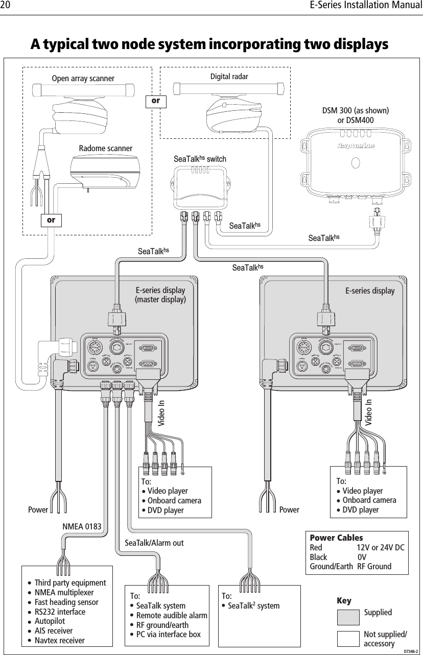
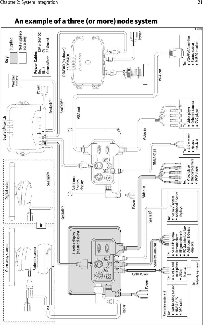
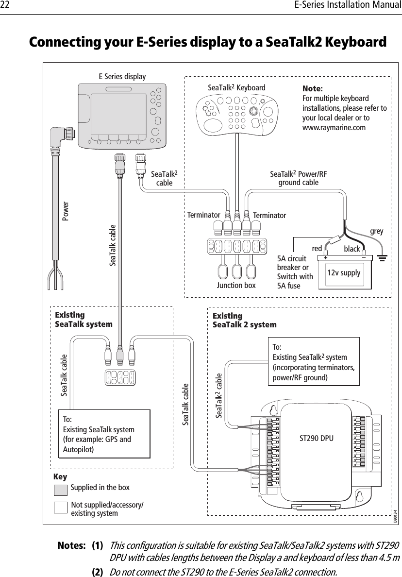
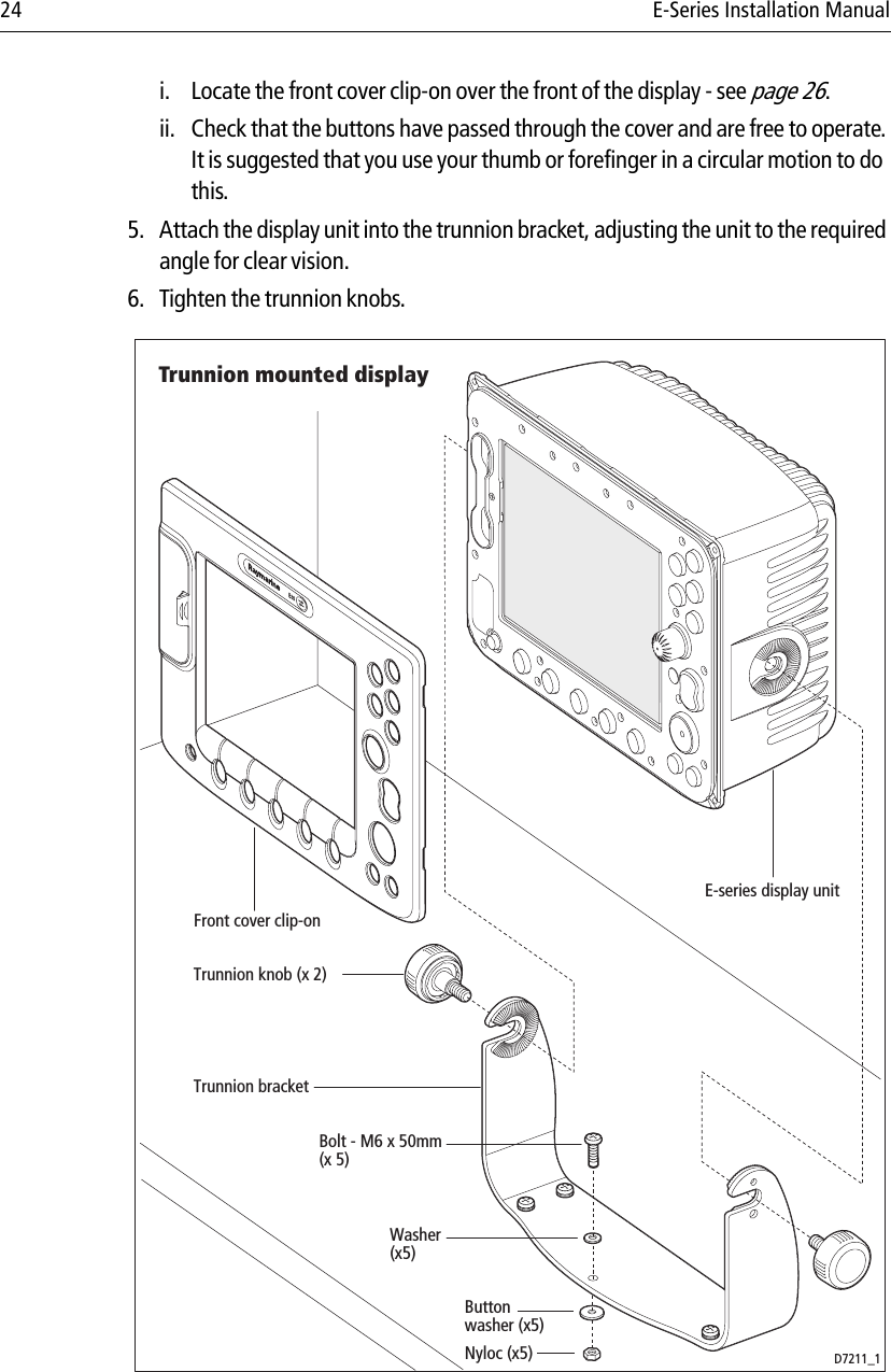
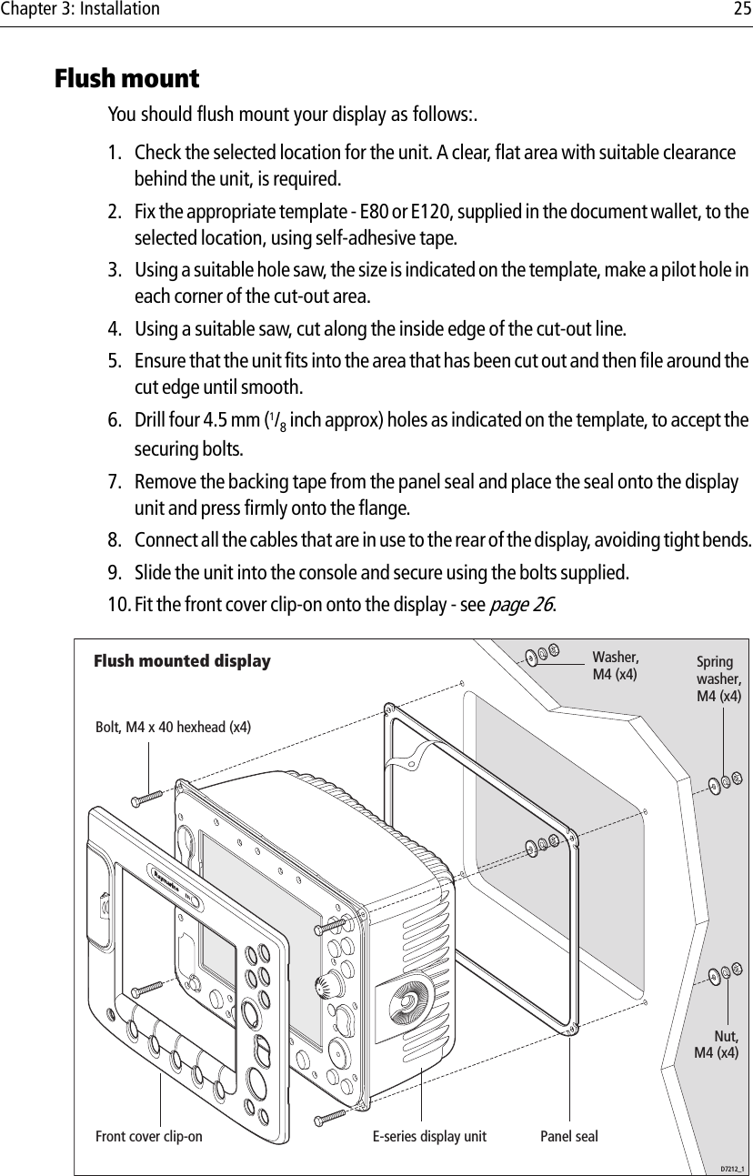
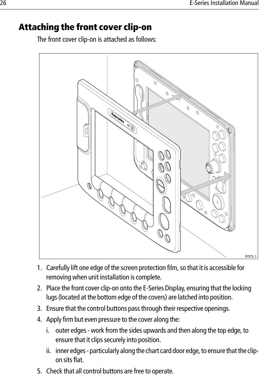
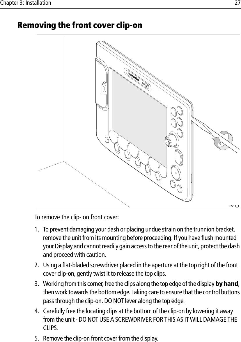
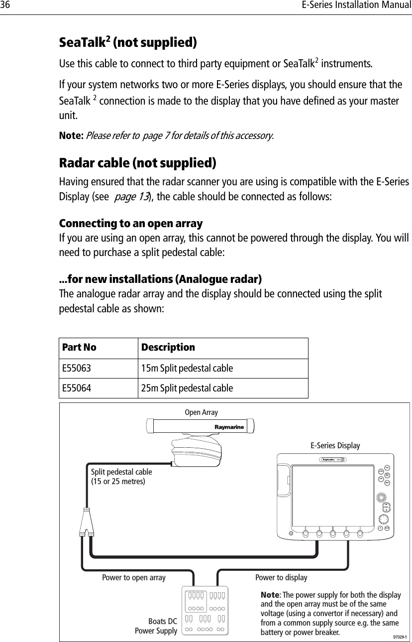
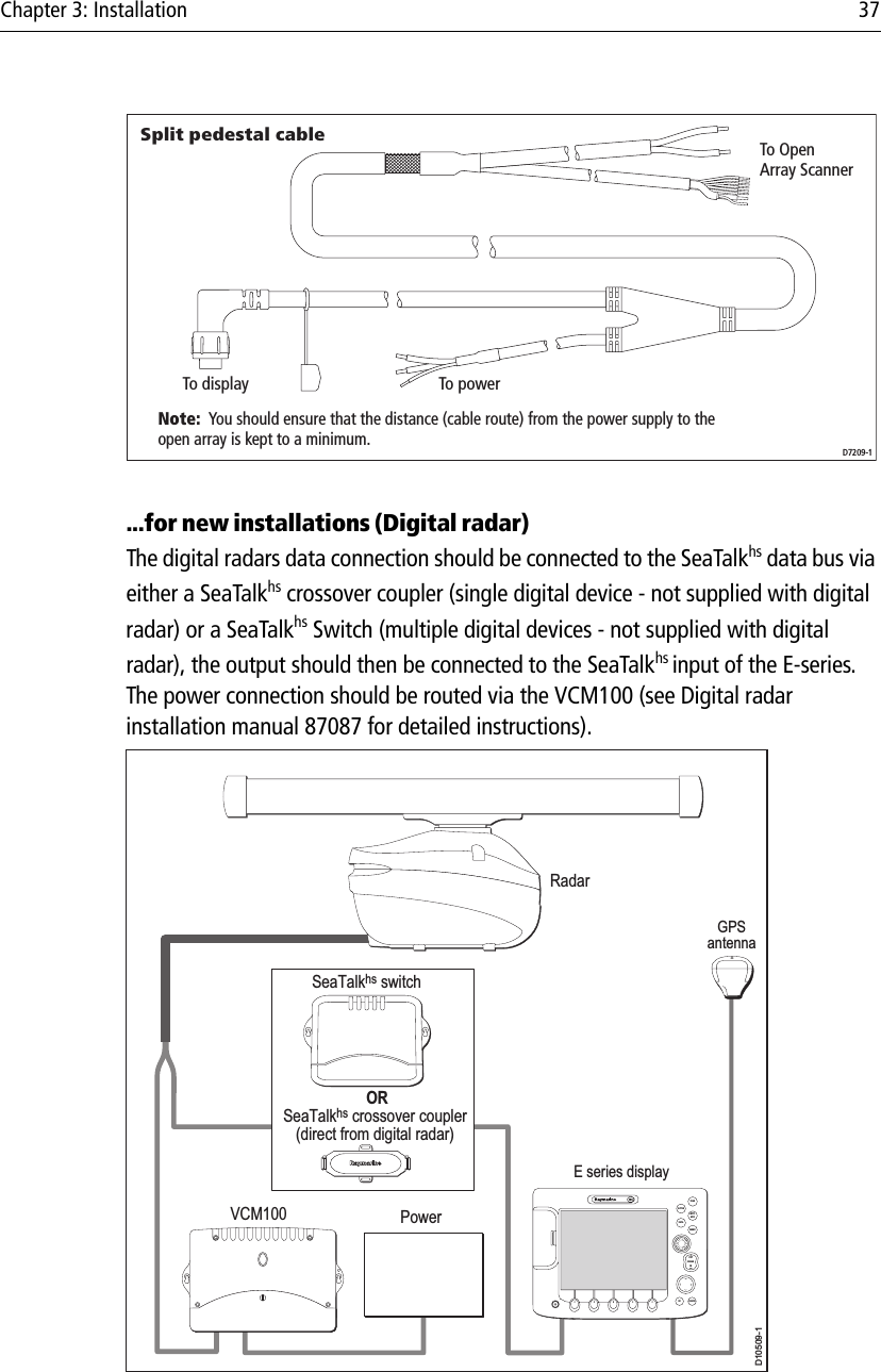
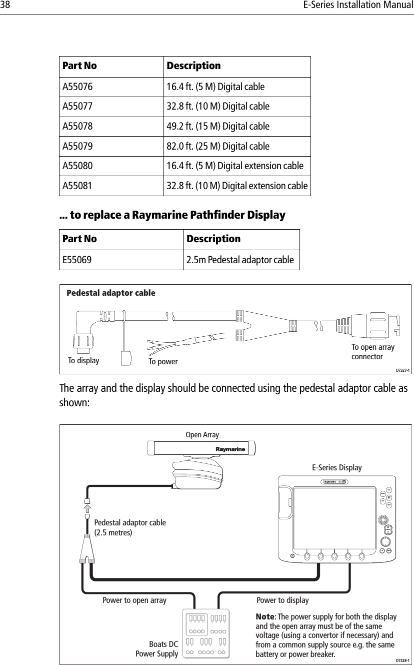
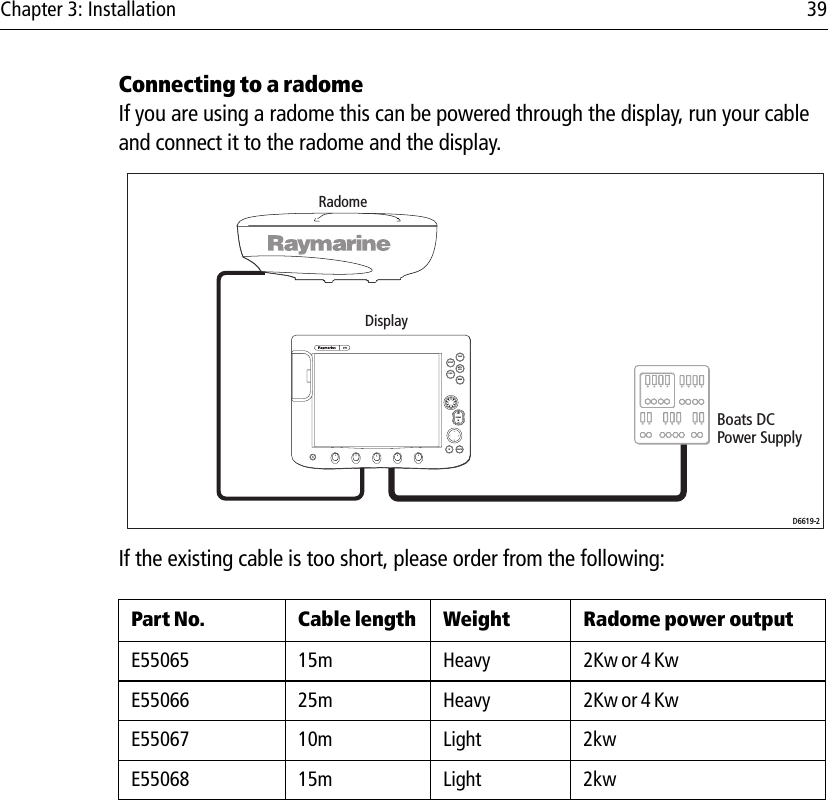
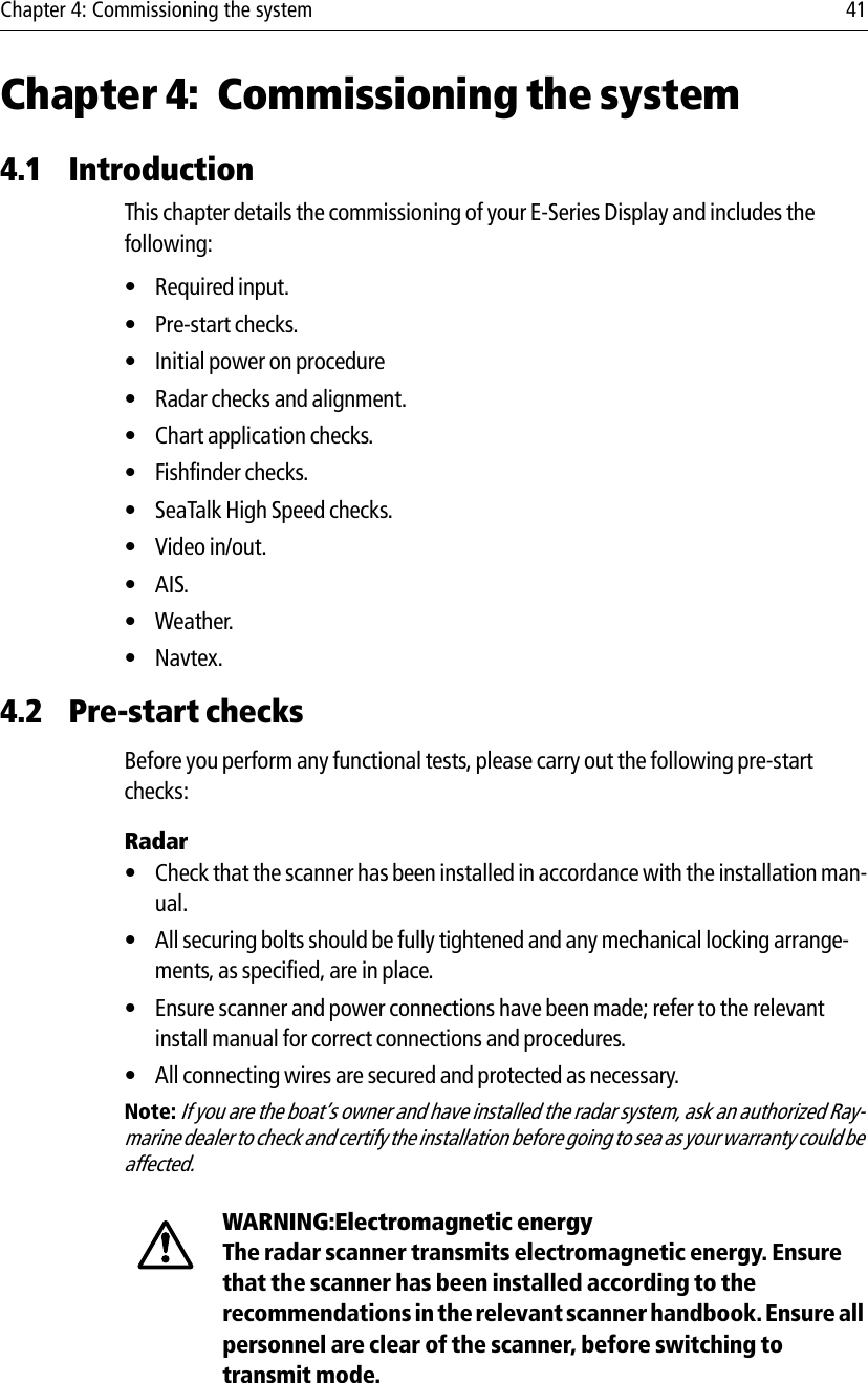
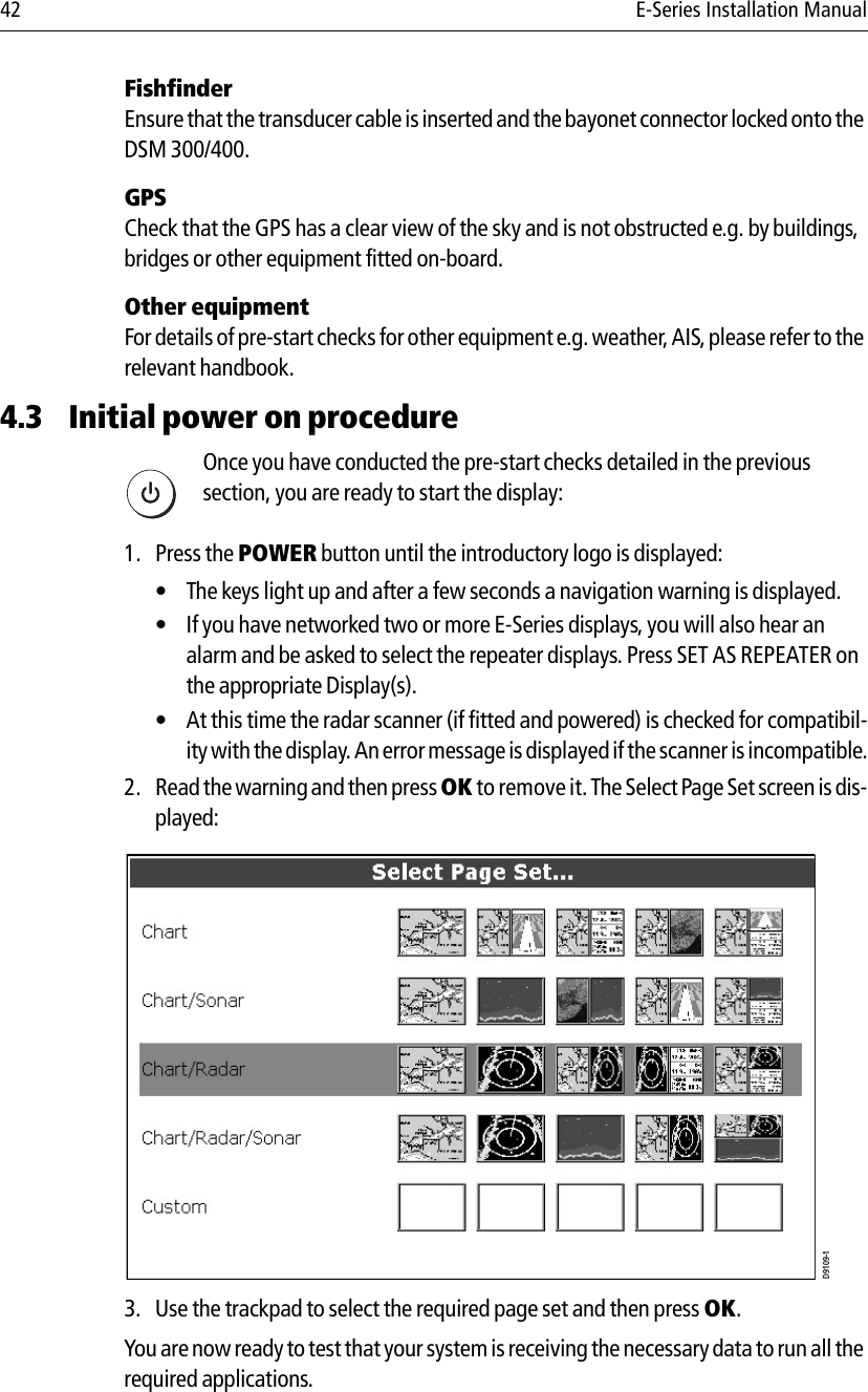
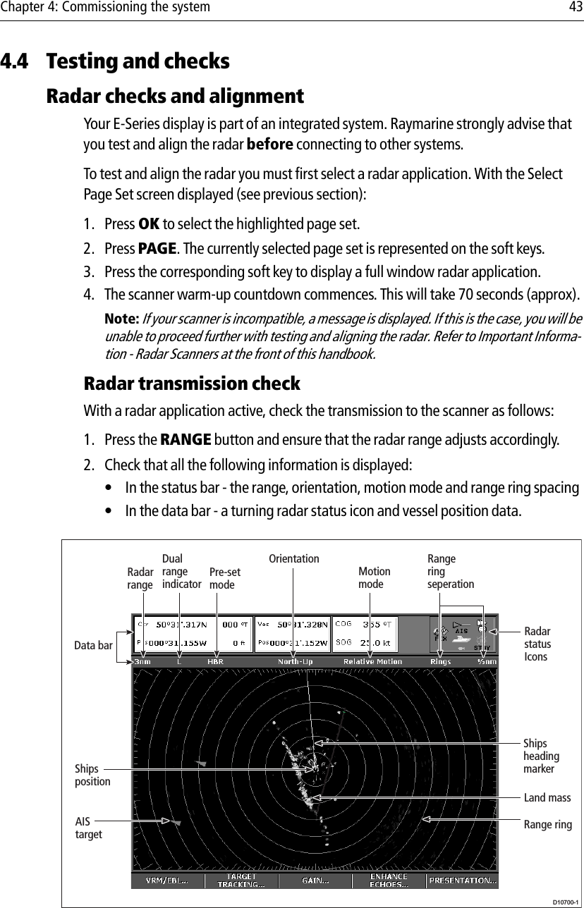
Installation guide
3.
Operating guide
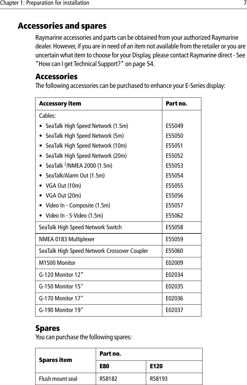
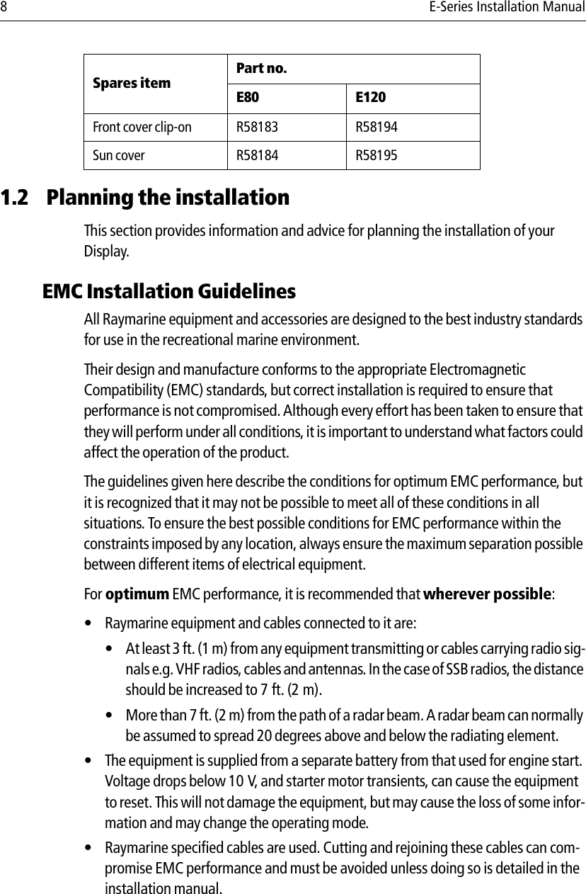
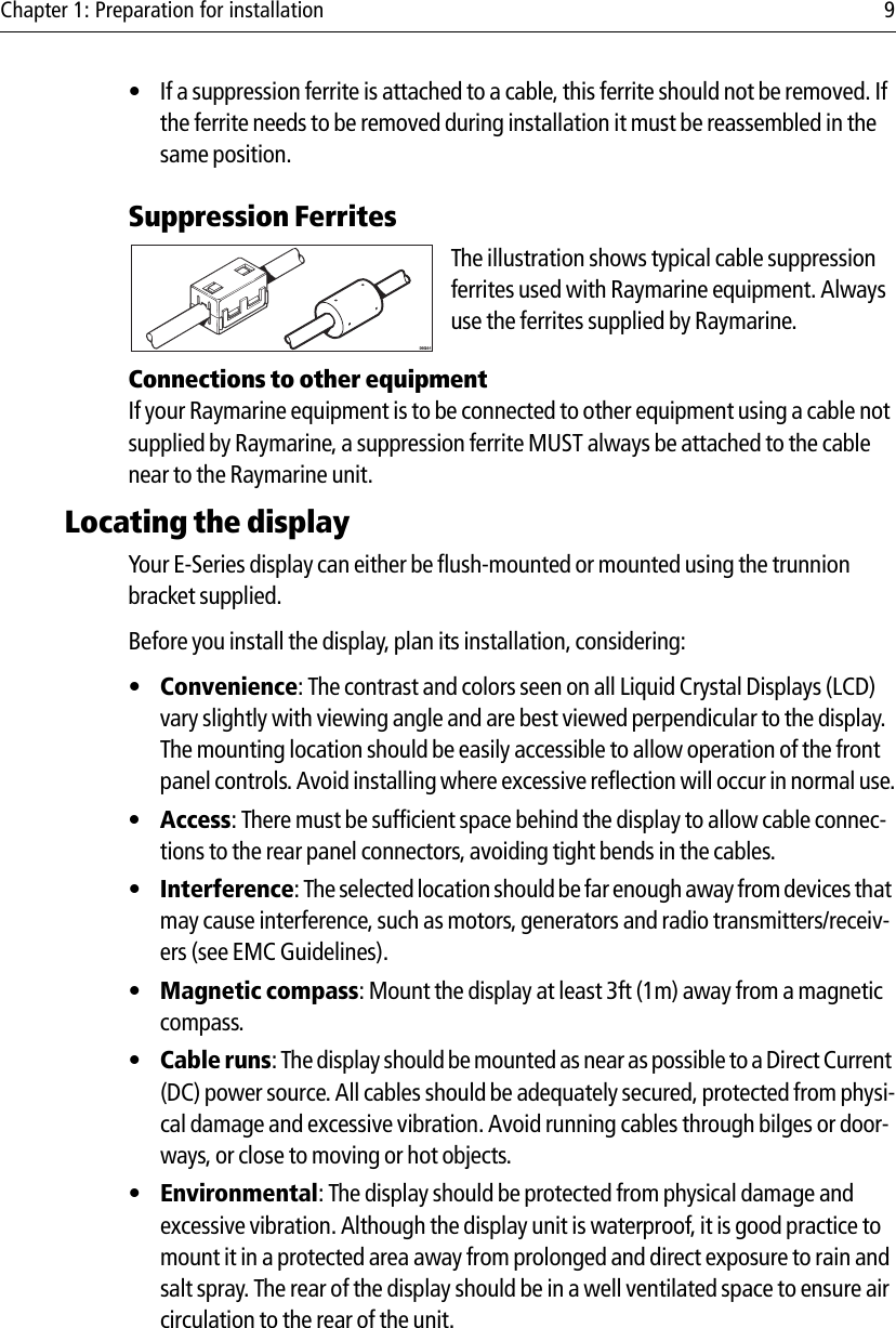
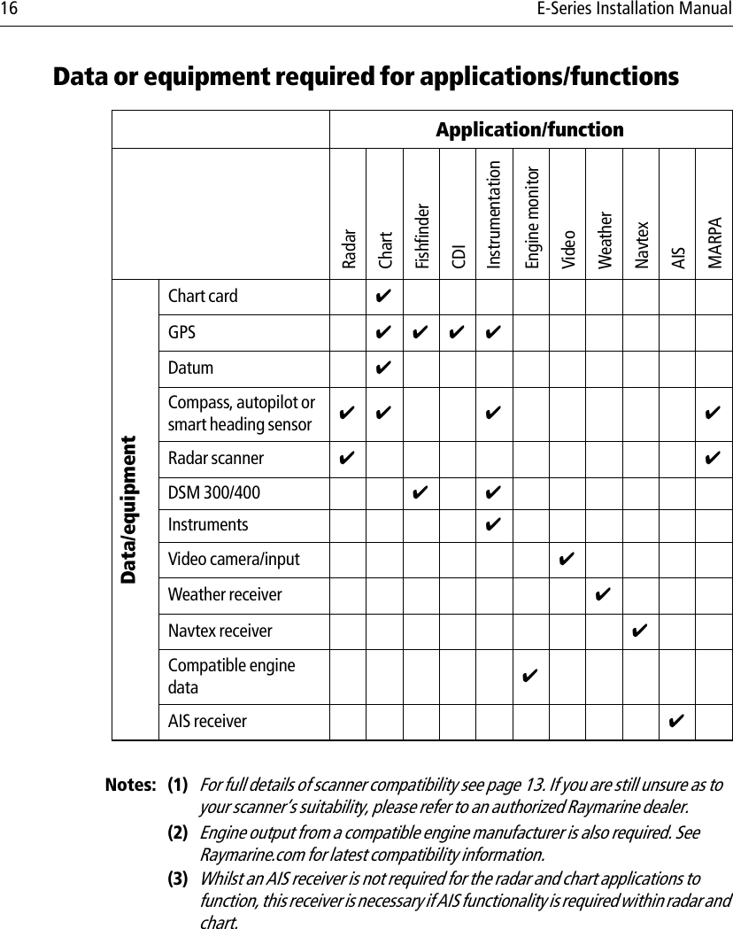
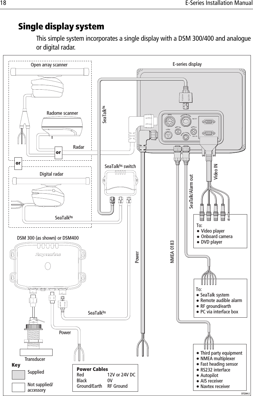
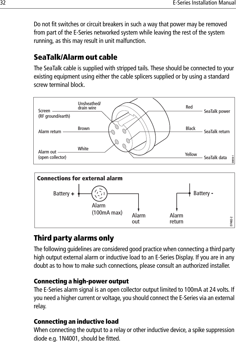
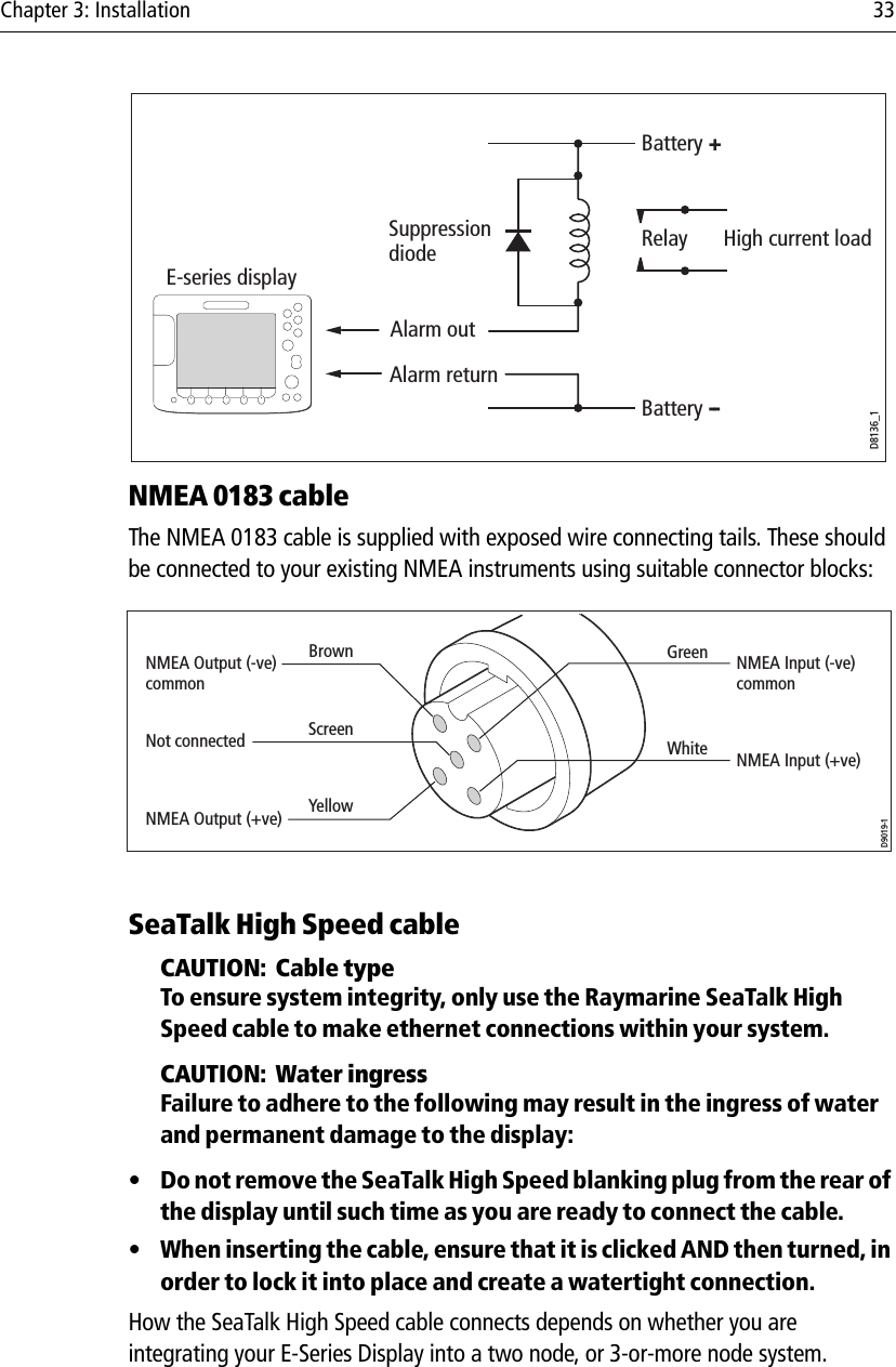
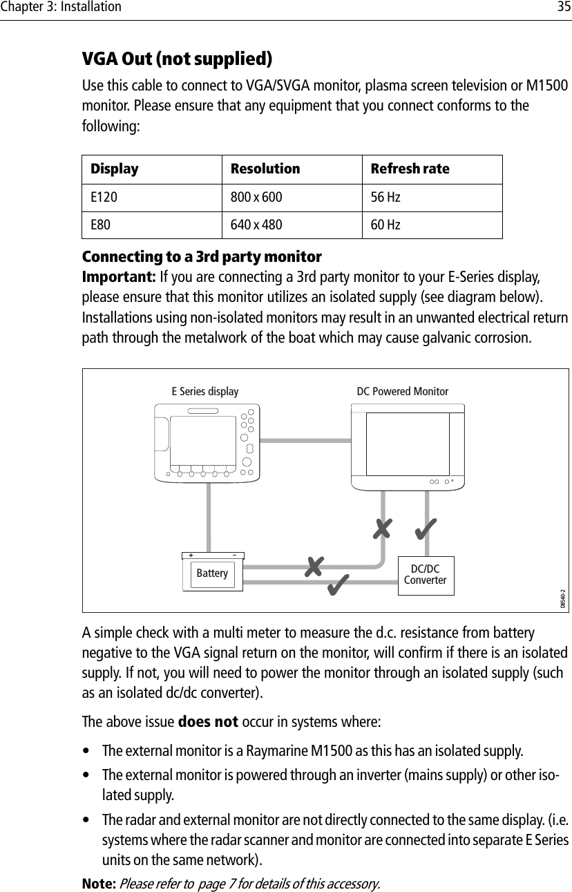
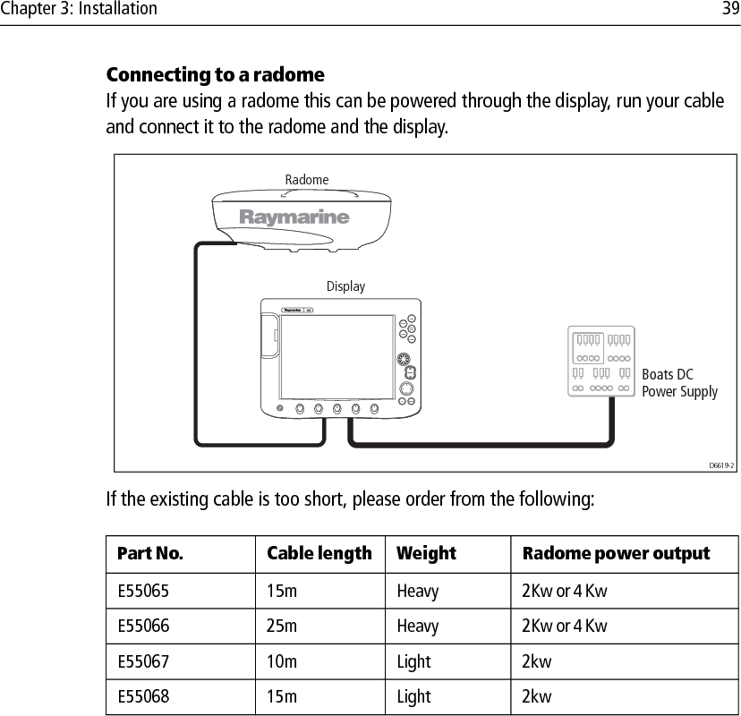
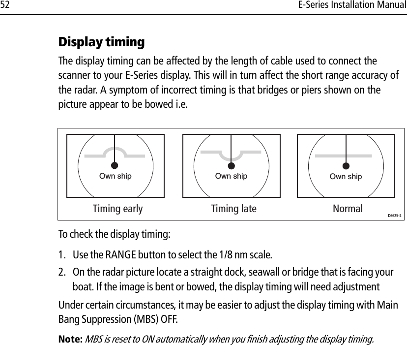
Installation guide
Navigation menu
Upload a User Manual
Namespaces
Wiki Guide
HTML
PDF
Info
Views
User Manual
Discussion / Help
Navigation