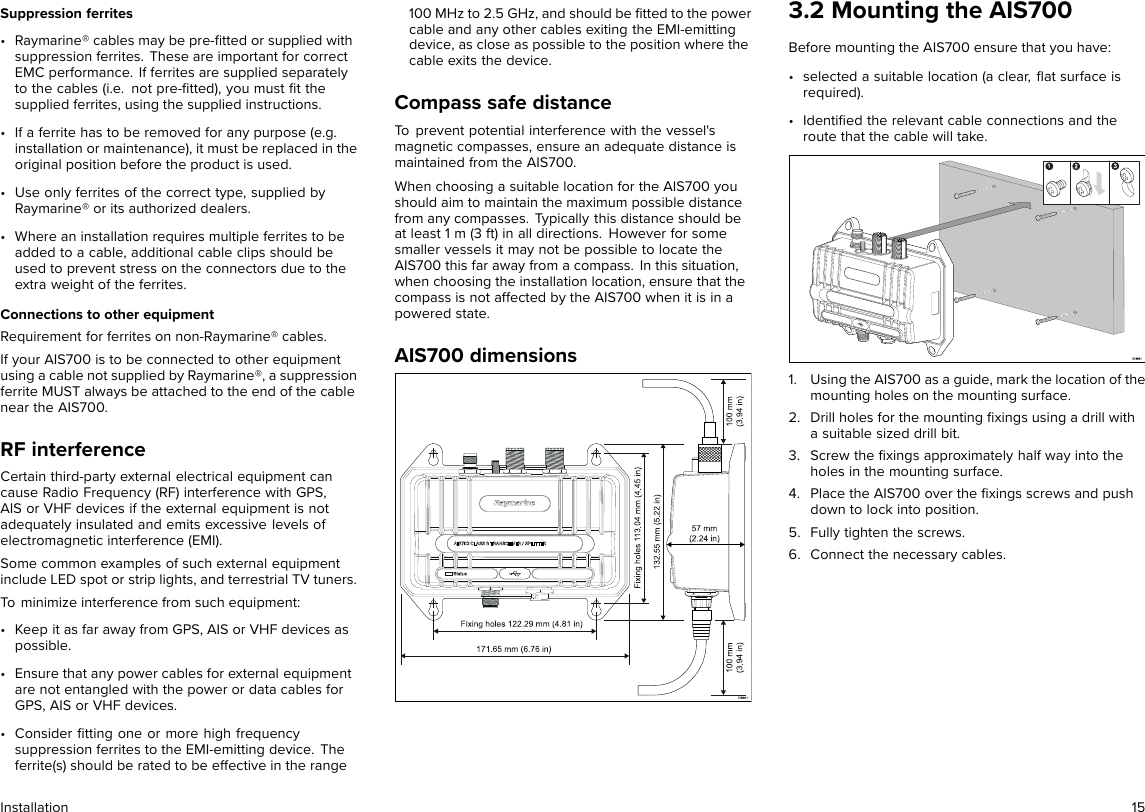
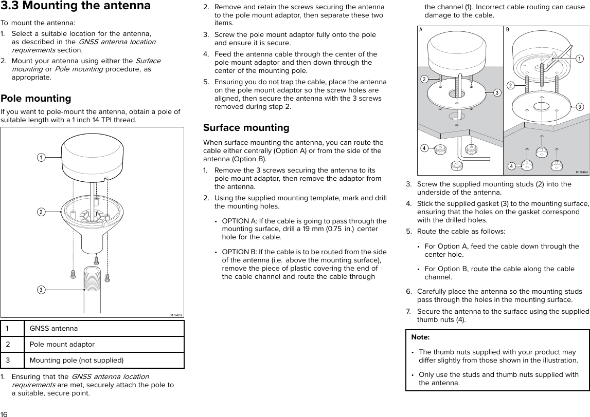
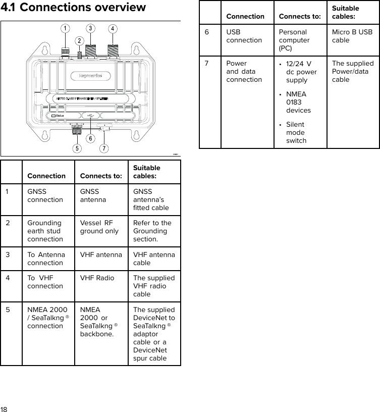
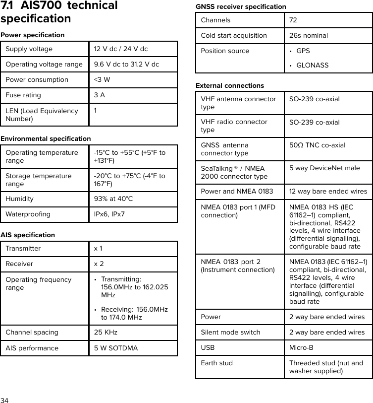
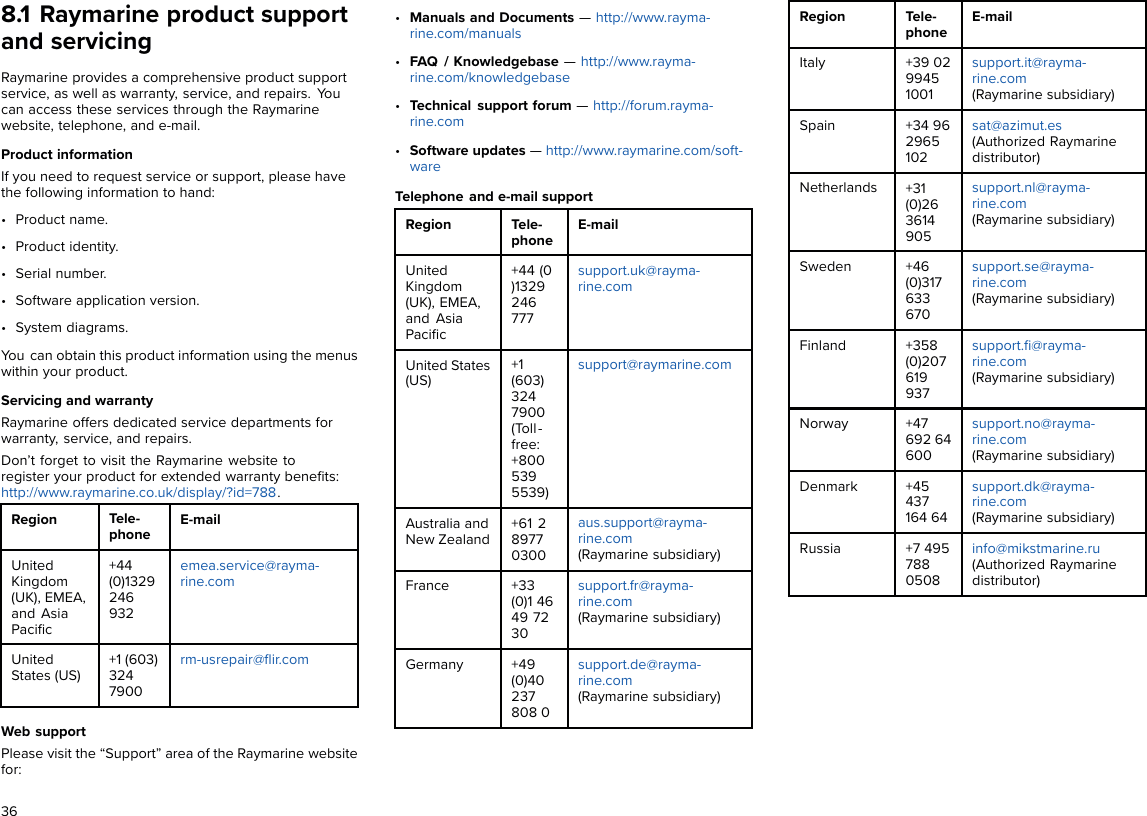
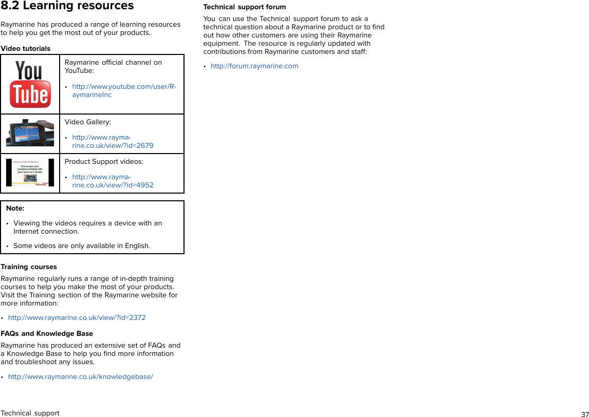
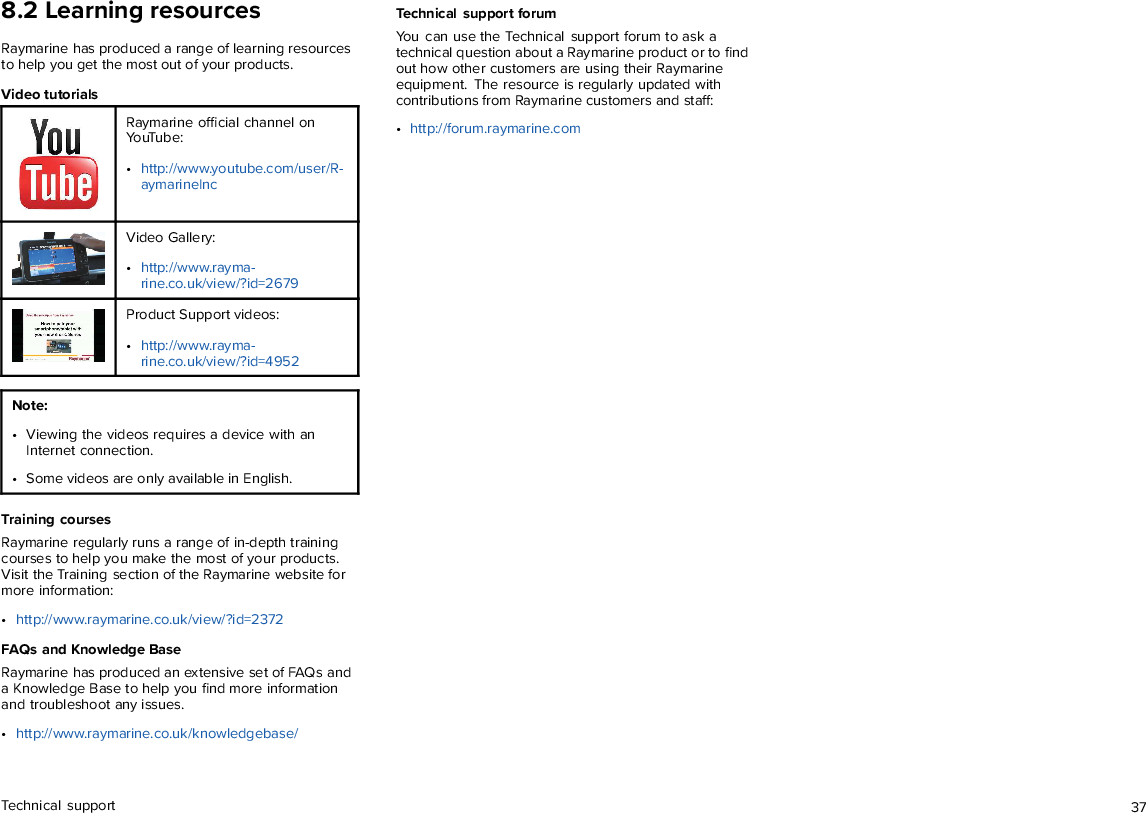
Flir BelgiumBA 428-0004B Marine Class B AIS Transceiver User Manual 87326 1 AIS700 installation instructions

Raymarine UK Ltd. Marine Class B AIS Transceiver 87326 1 AIS700 installation instructions

87326-1 AIS700_installation_instructions

© 2017 Raymarine UK Limited87326-1Document number:10-2017Date:English (en-US)Installation instructionsAIS700 Class B transceiver
Trademark and patents noticeRaymarine,Tacktick,Clear Pulse,Truzoom,HSB,SeaTalk ,SeaTalk hs,SeaTalk ng,Micronet,Raytech,Gear Up,Marine Shield,Seahawk,Autohelm,Automagic, and Visionalityare registered or claimed trademarks of Raymarine Belgium.FLIR,LightHouse,DownVision,SideVision,RealVision,Dragonfly,Quantum,Instalert,Infrared Everywhere,The World’s Sixth Sense and ClearCruise are registered orclaimed trademarks of FLIR Systems, Inc.All other trademarks, trade names, or company names referenced herein are used for identification only and are the property of their respective owners.This product is protected by patents, design patents, patents pending, or design patents pending.Fair Use StatementYou may print no more than three copies of this manual for your own use. You may not make any further copies or distribute or use the manual in any other way including withoutlimitation exploiting the manual commercially or giving or selling copies to third parties.Software updatesCheck the Raymarine® website for the latest software releases for your product.www.raymarine.com/softwareProduct documentationThe latest versions of all English and translated documents are available to download in PDF format from the website:www.raymarine.com/manuals.Please check the website to ensure you have the latest documentation.Copyright ©2017 Raymarine UK Ltd. All rights reserved.English (en-US)Document number: 87326-1
ContentsChapter 1 Important information ....................................... 7Product installation and operation . . . . . . . . . . . . . . . . . . . . . . . . . . . . . . . . . . . . . . 7Service and maintenance. . . . . . . . . . . . . . . . . . . . . . . . . . . . . . . . . . . . . . . . . . . . . . . . 7RF safety notice. . . . . . . . . . . . . . . . . . . . . . . . . . . . . . . . . . . . . . . . . . . . . . . . . . . . . . . . . . . 7Compliance Statement (Part 15.19) . . . . . . . . . . . . . . . . . . . . . . . . . . . . . . . . . . . . . . 7FCC Interference Statement (Part 15.105 (b)) . . . . . . . . . . . . . . . . . . . . . . . . . . 7Industry Canada . . . . . . . . . . . . . . . . . . . . . . . . . . . . . . . . . . . . . . . . . . . . . . . . . . . . . . . . . . 7Industry Canada (Français) . . . . . . . . . . . . . . . . . . . . . . . . . . . . . . . . . . . . . . . . . . . . . . 7Declaration of conformity . . . . . . . . . . . . . . . . . . . . . . . . . . . . . . . . . . . . . . . . . . . . . . . . 8AIS disclaimer. . . . . . . . . . . . . . . . . . . . . . . . . . . . . . . . . . . . . . . . . . . . . . . . . . . . . . . . . . . . . 8Disclaimer . . . . . . . . . . . . . . . . . . . . . . . . . . . . . . . . . . . . . . . . . . . . . . . . . . . . . . . . . . . . . . . . . 8Product disposal. . . . . . . . . . . . . . . . . . . . . . . . . . . . . . . . . . . . . . . . . . . . . . . . . . . . . . . . . . 8Warranty registration. . . . . . . . . . . . . . . . . . . . . . . . . . . . . . . . . . . . . . . . . . . . . . . . . . . . . 8Technical accuracy . . . . . . . . . . . . . . . . . . . . . . . . . . . . . . . . . . . . . . . . . . . . . . . . . . . . . . . 8Chapter 2 Document and product information .................... 92.1 Product documentation . . . . . . . . . . . . . . . . . . . . . . . . . . . . . . . . . . . . . . . . . . . . . 102.2 Applicable products . . . . . . . . . . . . . . . . . . . . . . . . . . . . . . . . . . . . . . . . . . . . . . . . 10Obtain MMSI (Maritime Mobile Service Identity) number . . . . . . . . . . . . . . . . . 102.3 Compatible displays . . . . . . . . . . . . . . . . . . . . . . . . . . . . . . . . . . . . . . . . . . . . . . . . . 112.4 Parts supplied . . . . . . . . . . . . . . . . . . . . . . . . . . . . . . . . . . . . . . . . . . . . . . . . . . . . . . . . 11Chapter 3 Installation .................................................... 133.1 Selecting a location. . . . . . . . . . . . . . . . . . . . . . . . . . . . . . . . . . . . . . . . . . . . . . . . . . 14General location requirements . . . . . . . . . . . . . . . . . . . . . . . . . . . . . . . . . . . . . . . . . . 14GNSS antenna location requirements . . . . . . . . . . . . . . . . . . . . . . . . . . . . . . . . . . . 14EMC installation guidelines. . . . . . . . . . . . . . . . . . . . . . . . . . . . . . . . . . . . . . . . . . . . . . 14RF interference . . . . . . . . . . . . . . . . . . . . . . . . . . . . . . . . . . . . . . . . . . . . . . . . . . . . . . . . . 15Compass safe distance. . . . . . . . . . . . . . . . . . . . . . . . . . . . . . . . . . . . . . . . . . . . . . . . . . 15AIS700 dimensions . . . . . . . . . . . . . . . . . . . . . . . . . . . . . . . . . . . . . . . . . . . . . . . . . . . . . 153.2 Mounting the AIS700 . . . . . . . . . . . . . . . . . . . . . . . . . . . . . . . . . . . . . . . . . . . . . . . 153.3 Mounting the antenna . . . . . . . . . . . . . . . . . . . . . . . . . . . . . . . . . . . . . . . . . . . . . . 16Pole mounting . . . . . . . . . . . . . . . . . . . . . . . . . . . . . . . . . . . . . . . . . . . . . . . . . . . . . . . . . . 16Surface mounting . . . . . . . . . . . . . . . . . . . . . . . . . . . . . . . . . . . . . . . . . . . . . . . . . . . . . . . 16Chapter 4 Connections .................................................. 174.1 Connections overview. . . . . . . . . . . . . . . . . . . . . . . . . . . . . . . . . . . . . . . . . . . . . . . 18Data connections matrix. . . . . . . . . . . . . . . . . . . . . . . . . . . . . . . . . . . . . . . . . . . . . . . . . 194.2 USB connection . . . . . . . . . . . . . . . . . . . . . . . . . . . . . . . . . . . . . . . . . . . . . . . . . . . . . 204.3 Power connection . . . . . . . . . . . . . . . . . . . . . . . . . . . . . . . . . . . . . . . . . . . . . . . . . . . 20Power distribution. . . . . . . . . . . . . . . . . . . . . . . . . . . . . . . . . . . . . . . . . . . . . . . . . . . . . . 20Grounding . . . . . . . . . . . . . . . . . . . . . . . . . . . . . . . . . . . . . . . . . . . . . . . . . . . . . . . . . . . . . 224.4 NMEA 2000 / SeaTalkng ® connection . . . . . . . . . . . . . . . . . . . . . . . . . . . . 224.5 NMEA 0183 connection. . . . . . . . . . . . . . . . . . . . . . . . . . . . . . . . . . . . . . . . . . . . . 234.6 GPS (GNSS) antenna connection . . . . . . . . . . . . . . . . . . . . . . . . . . . . . . . . . . 234.7 VHF antenna connection . . . . . . . . . . . . . . . . . . . . . . . . . . . . . . . . . . . . . . . . . . . 24VHF antenna requirements. . . . . . . . . . . . . . . . . . . . . . . . . . . . . . . . . . . . . . . . . . . . . 244.8 VHF radio connection . . . . . . . . . . . . . . . . . . . . . . . . . . . . . . . . . . . . . . . . . . . . . . 244.9 Silent mode switch connection . . . . . . . . . . . . . . . . . . . . . . . . . . . . . . . . . . . . 24Chapter 5 Set up ......................................................... 255.1 Configure before use. . . . . . . . . . . . . . . . . . . . . . . . . . . . . . . . . . . . . . . . . . . . . . . . 265.2 Obtain MMSI (Maritime Mobile Service Identity)number . . . . . . . . . . . . . . . . . . . . . . . . . . . . . . . . . . . . . . . . . . . . . . . . . . . . . . . . . . . . . . . . . . . 265.3 Configuration . . . . . . . . . . . . . . . . . . . . . . . . . . . . . . . . . . . . . . . . . . . . . . . . . . . . . . . . 26Installing proAIS2 and USB drivers . . . . . . . . . . . . . . . . . . . . . . . . . . . . . . . . . . . . . 27Configuring using proAIS2 . . . . . . . . . . . . . . . . . . . . . . . . . . . . . . . . . . . . . . . . . . . . . 275.4 Software updates . . . . . . . . . . . . . . . . . . . . . . . . . . . . . . . . . . . . . . . . . . . . . . . . . . . 275
Chapter 6 Troubleshooting ............................................ 296.1 LED Status indicator . . . . . . . . . . . . . . . . . . . . . . . . . . . . . . . . . . . . . . . . . . . . . . . . . 306.2 Troubleshooting. . . . . . . . . . . . . . . . . . . . . . . . . . . . . . . . . . . . . . . . . . . . . . . . . . . . . 30Chapter 7 Technical specification ................................... 337.1 AIS700 technical specification . . . . . . . . . . . . . . . . . . . . . . . . . . . . . . . . . . . . . 34Chapter 8 Technical support .......................................... 358.1 Raymarine product support and servicing . . . . . . . . . . . . . . . . . . . . . . . . 368.2 Learning resources . . . . . . . . . . . . . . . . . . . . . . . . . . . . . . . . . . . . . . . . . . . . . . . . . 37Chapter 9 Spares and accessories .................................. 399.1 Spares and accessories. . . . . . . . . . . . . . . . . . . . . . . . . . . . . . . . . . . . . . . . . . . . . 409.2 SeaTalk ng® cables and accessories. . . . . . . . . . . . . . . . . . . . . . . . . . . . . . . . 40Appendix A MMSI Regulatory bodies and applicationsubmissions................................................................ 43Appendix B NMEA 0183 supported sentences................... 45Appendix C NMEA 2000 supported PGNs ........................ 45Appendix D AIS overview .............................................. 466
Chapter 1: ImportantinformationProduct installation andoperationEnsure safe effective use of the product.• This product must be installed and operated inaccordance with the instructions provided. Failure todo so could result in personal injury, damage to yourvessel and/or poor product performance.• Raymarine® recommends certified installation by aRaymarine® approved installer. A certified installationqualifies for enhanced product warranty benefits.Contact your Raymarine® dealer for further details,and refer to the separate warranty document packedwith your product.Warning: Potential ignitionsourceThis product is NOT approved for use inhazardous/flammable atmospheres. DoNOT install in a hazardous/flammableatmosphere (such as in an engine room ornear fuel tanks).Service and maintenanceThis product contains no user serviceable components.Please refer all maintenance and repair to authorizedRaymarine® dealers. Unauthorized repair may affectyour warranty.RF safety noticeRF radiation statementAIS transceivers generate and radiate radio frequency(RF) electromagnetic energy (EME).Compliance Statement (Part15.19)This device complies with Part 15 of the FCC Rules.Operation is subject to the following two conditions:1. This device may not cause harmful interference.2. This device must accept any interference received,including interference that may cause undesiredoperation.FCC Interference Statement(Part 15.105 (b))This equipment has been tested and found to complywith the limits for a Class B digital device, pursuant toPart 15 of the FCC Rules.These limits are designed to provide reasonableprotection against harmful interference in a residentialinstallation. This equipment generates, uses, and canradiate radio frequency energy and, if not installed andused in accordance with the instructions, may causeharmful interference to radio communications. However,there is no guarantee that interference will not occur ina particular installation. If this equipment does causeharmful interference to radio or television reception,which can be determined by turning the equipment offand on, the user is encouraged to try to correct theinterference by one of the following measures:1. Reorient or relocate the receiving antenna.2. Increase the separation between the equipmentand receiver.3. Connect the equipment into an outlet on acircuit different from that to which the receiver isconnected.4. Consult the dealer or an experienced radio / TVtechnician for help.Warning: FCC Warning (Part15.21)Changes or modifications to this equipmentnot expressly approved in writing byRaymarine Incorporated could violatecompliance with FCC rules and void theuser’s authority to operate the equipment.Industry CanadaThis device complies with Industry CanadaLicense-exempt RSS standard(s).Operation is subject to the following two conditions:1. This device may not cause interference; and2. This device must accept any interference, includinginterference that may cause undesired operationof the device.This Class B digital apparatus complies with CanadianICES-003.Industry Canada (Français)Cet appareil est conforme aux normes d'exemption delicence RSS d'Industry Canada.Son fonctionnement est soumis aux deux conditionssuivantes:1. cet appareil ne doit pas causer d'interférence, et2. cet appareil doit accepter toute interférence,notamment les interférences qui peuvent affecterson fonctionnement.Cet appareil numérique de la classe B est conforme à lanorme NMB-003 du Canada.Important information 7
Declaration of conformityRaymarine® declares that this product is compliant withthe essential requirements of Radio Equipment Directive2014/53/EU.The original Declaration of Conformity certificatemay be viewed on the relevant product page atwww.raymarine.com.AIS disclaimerAll information presented by the AIS700 is advisoryonly, as there is a risk of incomplete and erroneousinformation. By placing this product into service youacknowledge this and assume complete responsibilityfor any associated risks, and accordingly releaseRaymarine® and SRT Marine Systems plc from any andall claims arising from the use of the AIS service.DisclaimerRaymarine® does not warrant that this product iserror-free or that it is compatible with productsmanufactured by any person or entity other thanRaymarine®.Raymarine® is not responsible for damages or injuriescaused by your use or inability to use the product, by theinteraction of the product with products manufacturedby others, or by errors in information utilized by theproduct supplied by third parties.Product disposalDispose of this product in accordance with the WEEEDirective.The Waste Electrical and Electronic Equipment(WEEE) Directive requires the recycling of wasteelectrical and electronic equipment.Warranty registrationWarranty registrations and associated benefits.To register your Raymarine® product ownership, pleasevisit www.raymarine.com/warranty and register online.It is important that you register your product to receivefull warranty benefits. Your unit package includes abar code label indicating the serial number of the unit.You will need this serial number when registering yourproduct online. You should retain the label for futurereference.Technical accuracyTechnical accuracy disclaimerTo the best of our knowledge, the information in thisdocument was correct at the time it was produced.However, Raymarine® cannot accept liability for anyinaccuracies or omissions it may contain. In addition, ourpolicy of continuous product improvement may changespecifications without notice. As a result, Raymarine®cannot accept liability for any differences betweenthe product and this document. Please check theRaymarine® website (www.raymarine.com/manuals) toensure you have the most up-to-date version(s) of thedocumentation for your product.8
Chapter 2: Document and product informationChapter contents• 2.1 Product documentation on page 10• 2.2 Applicable products on page 10• 2.3 Compatible displays on page 11• 2.4 Parts supplied on page 11Document and product information 9
2.1 Product documentationThe following documentation is applicable to yourproduct:All documents are available to download as PDFs fromwww.raymarine.comDocumentationDescription Part numberAIS700 Installation instructions (Thisdocument)Installation of a AIS700 andconnection to a wider system ofmarine electronics.87326GNSS antenna Mounting templateMounting diagram for the AIS700’sGNSS receiver.87225LightHouse™ 3 OperationinstructionsOperation instructions for compatibleLightHouse™ 3 displays.81370LightHouse™ 2 OperationinstructionsOperation instructions for compatibleLightHouse™ 2 displays.813602.2 Applicable productsThis document is applicable to the following products:Productnumber Name DescriptionE70476 AIS700 The AIS700 is a ClassB AIS transceiver witha built-in VHF splitter,used to display real-timeinformation on local vessels,land based stations or aidsto navigation that areequipped with eitherClass A or Class B AIStransceivers.Obtain MMSI (Maritime Mobile ServiceIdentity) numberBefore commencing installation ensure you haveobtained a MMSI number for your vessel.A MMSI is a 9 digit number which is sent over a radiofrequency channel in order to identify the originatingvessel/station. If your vessel already has a MMSI number(used for a VHF DSC radio) then the same MMSI numbermust be used to program your AIS700.Note:If a MMSI number is not entered, the AIS700 canonly be used in Silent Mode and will operate as areceiver only.In the United States of America, the MMSI and StaticData must be entered only by a Raymarine® dealeror other appropriately qualified installer of marinecommunications equipment on board vessels.The user is NOT authorized to do this.In some areas, a radio operator licence is requiredbefore a MMSI number will be issued. You can requesta MMSI number from same agency that issues radio orShip Radio licences in your area.In Europe and other parts of the world outside of theUnited States of America, the MMSI and Static data canbe set up by the user.For further details, refer to the relevantTelecommunications Regulatory Body for yourarea.Refer to Appendix A MMSI Regulatory bodies andapplication submissionsfor a list of contacts for obtaining MMSI numbers forsome areas.Warning: MMSI entryYou can only enter a MMSI number once, ifyou enter the number incorrectly or needto change your MMSI number, the unit willrequire re-programming by an authorizedRaymarine® dealer.10
2.3 Compatible displaysYou can view AIS information received by your AIS700on a compatible display.Your AIS700 is compatible with MFDs powered bythe LightHouse™ 2 or LightHouse™ 3 operating systemor multifunction instrument displays powered by theLightHouse™ operating system.2.4 Parts supplied1. AIS7002. GNSS antenna3. Power/data cable 2m (6.56 ft)4. VHF Radio cable 1m (3.28 ft)5. DeviceNet to SeaTalkng ® adaptor cable 1m (3.28 ft)6. GNSS antenna gasket7. GNSS antenna pole mount8. Unit fixings (4 x No.8x19 self tapping screws)9. M5 nut and washer (grounding)10. Documentation11. GNSS antenna fixings (3 x M3x40 stud and thumbnut)12. Software CDDocument and product information 11
12
Chapter 3: InstallationChapter contents• 3.1 Selecting a location on page 14• 3.2 Mounting the AIS700 on page 15• 3.3 Mounting the antenna on page 16Installation 13
3.1 Selecting a locationWarning: Potential ignitionsourceThis product is NOT approved for use inhazardous/flammable atmospheres. DoNOT install in a hazardous/flammableatmosphere (such as in an engine room ornear fuel tanks).General location requirementsWhen selecting a location for your AIS700 it is importantto consider a number of factors.•Water ingress — The AIS700 should be mountedbelow decks. Although the AIS700 is waterproof, it isgood practice to locate it in a protected area awayfrom prolonged and direct exposure to rain and saltspray.•Ventilation — To ensure adequate airflow:– Ensure that AIS700 is mounted in a compartmentof suitable size.– Ensure that ventilation holes are not obstructed.Allow adequate separation of all equipment.•Electrical interference — Select a location thatis far enough away from devices that may causeinterference, such as motors, generators and radiotransmitters / receivers.•Power supply — Select a location that is as close aspossible to the vessel’s DC power source. This willhelp to keep cable runs to a minimum.•Diagnostics — The AIS700 must be mounted in alocation where any diagnostics LEDs are easily visible.•Mounting surface — Ensure the AIS700 is adequatelysupported on a secure surface. Do not mount units orcut holes in places which may damage the structureof the vessel.•Cabling — Ensure the AIS700 is mounted in a locationwhich allows proper routing, support and connectionof cables:– Minimum bend radius of 100 mm (3.94 in) unlessotherwise stated.– Use cable clips to prevent stress on connectors.– If your installation requires multiple ferrites to beadded to a cable then additional cable clips shouldbe used to ensure the extra weight of the cable issupported.GNSS antenna location requirementsThe AIS700 includes a built-in GNSS receiver and issupplied with a GNSS antenna which must be installedin accordance with the instructions provided. Do NOTconnect any other GNSS antenna other than thatsupplied.The GNSS antenna can be mounted either on a flathorizontal surface or on a suitable pole.• If you intend to surface mount the antenna, ensure youhave access to the underside of the mounting surface.• If you intend to pole-mount the antenna, the poleneeds to have a 1 inch 14 TPI thread.Important:The GNSS antenna must be mounted in a locationthat provides a good direct line of site to the entiresky, around the horizon.Ensure that the selected mounting location is:• Open and clear of any obstructions (such as masts,search lights, or other structures) that could blockline-of-sight to the sky.• As low as possible, to keep the antenna as stableas possible. The more stable the antenna, the moreeffectively it will track satellites and provide stabledata.• As far as possible (at least 1 m (3 ft)) from otherantennae and electronic equipment.Do NOT mount the antenna:• In any area where it could be stepped on or trippedover.• Up a mast. This will cause the antenna to swing andgive significant errors in position data.• In the direct path of a Radar beam.EMC installation guidelinesRaymarine® equipment and accessories conform tothe appropriate Electromagnetic Compatibility (EMC)regulations, to minimize electromagnetic interferencebetween equipment and minimize the effect suchinterference could have on the performance of yoursystemCorrect installation is required to ensure that EMCperformance is not compromised.Note:In areas of extreme EMC interference, some slightinterference may be noticed. Where this occurs theAIS700 and the source of the interference should beseparated by a greater distance.For optimum EMC performance we recommend thatwherever possible:• Raymarine® equipment and cables connected to it are:– At least 1 m (3 ft) from any equipment transmittingor cables carrying radio signals e.g. VHF radios,cables and antennas. In the case of SSB radios, thedistance should be increased to 2 m (7 ft).– More than 2 m (7 ft) from the path of a Radar beam.A Radar beam can normally be assumed to spread20 degrees above and below the radiating element.• The AIS700 is supplied from a separate battery fromthat used for engine start. This is important to preventerratic behavior and data loss which can occur if theengine start does not have a separate battery.• Raymarine® specified cables are used.• Cables are not cut or extended, unless doing so isdetailed in the installation instructions.Note: Where constraints on the installation preventany of the above recommendations, always ensurethe maximum possible separation between differentitems of electrical equipment, to provide the bestconditions for EMC performance throughout theinstallation14
Suppression ferrites• Raymarine® cables may be pre-fitted or supplied withsuppression ferrites. These are important for correctEMC performance. If ferrites are supplied separatelyto the cables (i.e. not pre-fitted), you must fit thesupplied ferrites, using the supplied instructions.• If a ferrite has to be removed for any purpose (e.g.installation or maintenance), it must be replaced in theoriginal position before the product is used.• Use only ferrites of the correct type, supplied byRaymarine® or its authorized dealers.• Where an installation requires multiple ferrites to beadded to a cable, additional cable clips should beused to prevent stress on the connectors due to theextra weight of the ferrites.Connections to other equipmentRequirement for ferrites on non-Raymarine® cables.If your AIS700 is to be connected to other equipmentusing a cable not supplied by Raymarine®, a suppressionferrite MUST always be attached to the end of the cablenear the AIS700.RF interferenceCertain third-party external electrical equipment cancause Radio Frequency (RF) interference with GPS,AIS or VHF devices if the external equipment is notadequately insulated and emits excessive levels ofelectromagnetic interference (EMI).Some common examples of such external equipmentinclude LED spot or strip lights, and terrestrial TV tuners.To minimize interference from such equipment:• Keep it as far away from GPS, AIS or VHF devices aspossible.• Ensure that any power cables for external equipmentare not entangled with the power or data cables forGPS, AIS or VHF devices.• Consider fitting one or more high frequencysuppression ferrites to the EMI-emitting device. Theferrite(s) should be rated to be effective in the range100 MHz to 2.5 GHz, and should be fitted to the powercable and any other cables exiting the EMI-emittingdevice, as close as possible to the position where thecable exits the device.Compass safe distanceTo prevent potential interference with the vessel'smagnetic compasses, ensure an adequate distance ismaintained from the AIS700.When choosing a suitable location for the AIS700 youshould aim to maintain the maximum possible distancefrom any compasses. Typically this distance should beat least 1 m (3 ft) in all directions. However for somesmaller vessels it may not be possible to locate theAIS700 this far away from a compass. In this situation,when choosing the installation location, ensure that thecompass is not affected by the AIS700 when it is in apowered state.AIS700 dimensions3.2 Mounting the AIS700Before mounting the AIS700 ensure that you have:• selected a suitable location (a clear, flat surface isrequired).• Identified the relevant cable connections and theroute that the cable will take.1. Using the AIS700 as a guide, mark the location of themounting holes on the mounting surface.2. Drill holes for the mounting fixings using a drill witha suitable sized drill bit.3. Screw the fixings approximately half way into theholes in the mounting surface.4. Place the AIS700 over the fixings screws and pushdown to lock into position.5. Fully tighten the screws.6. Connect the necessary cables.Installation 15
3.3 Mounting the antennaTo mount the antenna:1. Select a suitable location for the antenna,as described in theGNSS antenna locationrequirementssection.2. Mount your antenna using either theSurfacemountingorPole mountingprocedure, asappropriate.Pole mountingIf you want to pole-mount the antenna, obtain a pole ofsuitable length with a 1 inch 14 TPI thread.1GNSS antenna2Pole mount adaptor3Mounting pole (not supplied)1. Ensuring that theGNSS antenna locationrequirementsare met, securely attach the pole toa suitable, secure point.2. Remove and retain the screws securing the antennato the pole mount adaptor, then separate these twoitems.3. Screw the pole mount adaptor fully onto the poleand ensure it is secure.4. Feed the antenna cable through the center of thepole mount adaptor and then down through thecenter of the mounting pole.5. Ensuring you do not trap the cable, place the antennaon the pole mount adaptor so the screw holes arealigned, then secure the antenna with the 3 screwsremoved during step 2.Surface mountingWhen surface mounting the antenna, you can route thecable either centrally (Option A) or from the side of theantenna (Option B).1. Remove the 3 screws securing the antenna to itspole mount adaptor, then remove the adaptor fromthe antenna.2. Using the supplied mounting template, mark and drillthe mounting holes.• OPTION A: If the cable is going to pass through themounting surface, drill a 19 mm (0.75 in.) centerhole for the cable.• OPTION B: If the cable is to be routed from the sideof the antenna (i.e. above the mounting surface),remove the piece of plastic covering the end ofthe cable channel and route the cable throughthe channel (1). Incorrect cable routing can causedamage to the cable.3. Screw the supplied mounting studs (2) into theunderside of the antenna.4. Stick the supplied gasket (3) to the mounting surface,ensuring that the holes on the gasket correspondwith the drilled holes.5. Route the cable as follows:• For Option A, feed the cable down through thecenter hole.• For Option B, route the cable along the cablechannel.6. Carefully place the antenna so the mounting studspass through the holes in the mounting surface.7. Secure the antenna to the surface using the suppliedthumb nuts (4).Note:• The thumb nuts supplied with your product maydiffer slightly from those shown in the illustration.• Only use the studs and thumb nuts supplied withthe antenna.16
Chapter 4: ConnectionsChapter contents• 4.1 Connections overview on page 18• 4.2 USB connection on page 20• 4.3 Power connection on page 20• 4.4 NMEA 2000 / SeaTalkng ® connection on page 22• 4.5 NMEA 0183 connection on page 23• 4.6 GPS (GNSS) antenna connection on page 23• 4.7 VHF antenna connection on page 24• 4.8 VHF radio connection on page 24• 4.9 Silent mode switch connection on page 24Connections 17
4.1 Connections overviewConnection Connects to:Suitablecables:1GNSSconnectionGNSSantennaGNSSantenna’sfitted cable2 Groundingearth studconnectionVessel RFground onlyRefer to theGroundingsection.3To AntennaconnectionVHF antenna VHF antennacable4 To VHFconnectionVHF Radio The suppliedVHF radiocable5NMEA 2000/ SeaTalkng ®connectionNMEA2000 orSeaTalkng ®backbone.The suppliedDeviceNet toSeaTalkng ®adaptorcable or aDeviceNetspur cableConnection Connects to:Suitablecables:6 USBconnectionPersonalcomputer(PC)Micro B USBcable7 Powerand dataconnection• 12/24 Vdc powersupply• NMEA0183devices• SilentmodeswitchThe suppliedPower/datacable18
Data connections matrixThe following table details the types of data that can be exchanged using the various combinations of data connections NMEA 0183 (Low / High baud rate), NMEA 2000 /SeaTalkng ®, and USB).It is important to choose the right combination of connections in order to exchange the types of data you require.As an example of how to use the table below, you can see that you can feed GNSS data into the AIS700 via a NMEA 0183 port configured for low baud rate (4,800), and then output italong with AIS data to the other NMEA 0183 port configured for high baud rate (38,400).When data is input on one NMEA 0183 port it is output on the other NMEA 0183 port, you cannot receive and send data on the same NMEA 0183 port.INPUTS OUTPUTSNMEA 0183 (4,800) NMEA 0183 (38,400) NMEA 2000,* / SeaTalkng ® USBGNSS AIS GNSS AIS GNSS AIS GNSS AISNMEA 0183(4,800)GNSSNMEA 0183(38,400)GNSSNMEA 2000 /SeaTalkng ®GNSSImportant:To avoid potential data conflicts or loops multiple network protocols should not be connected to the same device i.e.:• Do NOT connect the AIS700 to a MFD using NMEA 0183 and SeaTalkng ®/ NMEA 2000 connections at the same time.• Do NOT connect the AIS700 to a VHF Radio using NMEA 0183 and SeaTalkng ®/ NMEA 2000 connections at the same time.• Do NOT connect the AIS700 to a PC using NMEA 0183 and USB connections at the same time.• If you are connecting to an AIS capable VHF Radio, you must disable the VHF Radio’s AIS function first. Refer to your Radio’s documentation for details on disablingthe AIS function.Connections 19
4.2 USB connectionBefore using your AIS700 you must configure the unitusing the supplied proAIS2 software via a PC connectedto the USB connection.Important:In the United States of America, it is a violation of therules of the Federal Communications Commission toinput an MMSI that has not been properly assignedto the end user or to otherwise input any inaccuratedata in this device. The MMSI and Static Datamust be entered only by a Raymarine dealer orother appropriately qualified installer of marinecommunications equipment on board vessels.Ensure you check the regulations for your location toensure you are allowed to configure MMSI data onyour unit.1. AIS7002. USB Micro-B to type A cable (not supplied)3. PC (personal computer) running proAIS2Note:• The PC USB connection will provide power to theunit to enable configuration prior to installation.• Refer to Chapter 5 Set upfor details on configuring your AIS700.Warning: USB device powerDo NOT connect any device to the product’sUSB connection that requires an externalpower source.4.3 Power connection1. Power/data cable (supplied)2. Power supply – (Negative) Black wire3. Power supply + (Positive) Red wire4. Suitable waterproof connection (not supplied)5. Power cable extension to vessel’s circuitbreaker/power source6. Power source (12/24 V dc)Note: It is recommended that the power is suppliedvia a circuit breaker or that the unit is protected usinga 3 A inline fuse connected to the Red (+) positivewire.Power distributionRecommendations and best practice.• The product is supplied with a power cable. Only usethe power cable supplied with the product. Do NOTuse a power cable designed for, or supplied with, adifferent product.• Refer to thePower connectionsection for moreinformation on how to identify the wires in yourproduct’s power cable, and where to connect them.• See below for more information on implementation forsome common power distribution scenarios.20
Important:When planning and wiring, take into considerationother products in your system, some of which (e.g.sonar modules) may place large power demandpeaks on the vessel’s electrical system.Note:The information provided below is for guidance only,to help protect your product. It covers commonvessel power arrangements, but does NOT coverevery scenario. If you are unsure how to providethe correct level of protection, please consult anauthorized Raymarine dealer or a suitably qualifiedprofessional marine electrician.Implementation — direct connection to battery• The power cable supplied with your product maybe connected directly to the vessel's battery, via asuitably rated fuse or breaker.• The power cable supplied with your product may NOTinclude a separate drain wire. If this is the case, onlythe power cable’s red and black wires need to beconnected.• If the supplied power cable is NOT fitted with an inlinefuse, you MUST fit a suitably rated fuse or breakerbetween the red wire and the battery’s positiveterminal.• Refer to the inline fuse ratings provided in theproduct’s documentation.• If you need to extend the length of the power cablesupplied with your product, ensure you observe thededicatedPower cable extensionsadvice provided inthe product’s documentation.ABattery connection scenario A: suitable for avessel with a common RF ground point. Inthis scenario, if your product’s power cable issupplied with a separate drain wire then it shouldbe connected to the vessel’s common groundpoint.BBattery connection scenario B: suitable fora vessel without a common grounding point.In this case, if your product’s power cable issupplied with a separate drain wire then it shouldbe connected directly to the battery’s negativeterminal.Implementation — connection to distribution panel• Alternatively, the supplied power cable may beconnected to a suitable breaker or switch on thevessel's distribution panel or factory-fitted powerdistribution point.• The distribution point should be fed from the vessel’sprimary power source by 8 AWG (8.36 mm2) cable.• Ideally, all equipment should be wired to individualsuitably-rated thermal breakers or fuses, withappropriate circuit protection. Where this is notpossible and more than 1 item of equipment shares abreaker, use individual in-line fuses for each powercircuit to provide the necessary protection.1Positive (+) bar2Negative (-) bar3 Circuit breaker4 Fuse• In all cases, observe the recommended breaker / fuseratings provided in the product’s documentation.Important:Be aware that the suitable fuse rating for the thermalbreaker or fuse is dependent on the number ofdevices you are connecting.Power cable extensionIf you need to extend the length of the power cablesupplied with your product, ensure you observe thefollowing advice:• The power cable for each unit in your system shouldbe run as a separate, single length of 2-wire cableConnections 21
from the unit to the vessel's battery or distributionpanel.• For power cable extensions, it is recommended that aminimum wire gauge of 16 AWG (1.31 mm2). For cableruns longer than 15 meters, you may need to considera thicker wire gauge (e.g. 14 AWG (2.08 mm2), or 12AWG (3.31 mm2) ).• An important requirement for all lengths of powercable (including any extension) is to ensure that thereis a continuous minimum voltage of 10.8 V at theproduct’s power connector, with a fully flat battery at11 V.Important: Be aware that some products in yoursystem (such as sonar modules) can create voltagepeaks at certain times, which may impact the voltageavailable to other products during the peaks.GroundingEnsure that you observe the separate grounding adviceprovided in the product’s documentation.More informationIt is recommended that best practice is observed in allvessel electrical installations, as detailed in the followingstandards:• BMEA Code of Practice for Electrical and ElectronicInstallations in Boats• NMEA 0400 Installation Standard• ABYC E-11 AC & DC Electrical Systems on Boats• ABYC A-31 Battery chargers and Inverters• ABYC TE-4 Lightning ProtectionGroundingThe AIS700 includes a dedicated grounding point toreduce potential damage caused by near lightningstrikes.The Grounding point should be connected to yourvessel’s RF ground. Do NOT connect to any point that isconnected to your vessel’s 0V Negative battery terminal.1. M5 Nut (supplied)2. M5 Shakeproof washer (supplied)3. Grounding strap connected to vessel RF ground(not supplied)4. Grounding stud4.4 NMEA 2000 / SeaTalkng ®connectionThe AIS700 can transmit data to devices connected onSeaTalkng ® or NMEA 2000 CAN bus networks. TheAIS700 is connected using the DeviceNet connectorlocated on the bottom of the unit.1. Use the supplied DeviceNet to SeaTalkng ® adaptorcable to connect your AIS700 to an available spurconnection on a SeaTalkng ® backbone.2. Alternatively you can connect your AIS700 to aNMEA 2000 backbone using a standard DeviceNetcable (not supplied).Note:1. The AIS700 must be connected to a correctlyterminated backbone. You cannot connect yourAIS700 directly to a MFD.2. Refer to the instructions supplied with yourSeaTalkng ® / NMEA 2000 device for details oncreating a backbone.22
4.5 NMEA 0183 connectionThe AIS700 can transmit data to devices connected viaNMEA 0183. The AIS700 is connected using the NMEA0183 wires located on the Power/data cable.Note: Whilst it is possible to output both AIS andGNSS data, it is NOT recommended that you outputGNSS data to external devices as this can cause dataconflicts and / or performance issues. The abilityto output GNSS data is intended for diagnosticspurposes only.The AIS700 includes 2 bidirectional NMEA 0183 ports.The baud rate for each port can be configured usingthe supplied proAIS2 software. Both ports can bemultiplexed which enables any data provided to oneport to be combined with AIS data and output on theother port.Typically port 1 is connected to an MFD and configuredfor 38,400 baud rate, the baud rate required for AISdata transfer. Port 2 is connected to a Heading sensoror other NMEA 0183 device and configured for 4,800baud rate.Important:To avoid potential data conflicts or loops multiplenetwork protocols should not be connected to thesame device i.e.:• Do NOT connect the AIS700 to a MFD using NMEA0183 and SeaTalkng ®/ NMEA 2000 connectionsat the same time.• Do NOT connect the AIS700 to a VHF Radiousing NMEA 0183 and SeaTalkng ®/ NMEA 2000connections at the same time.• Do NOT connect the AIS700 to a PC using NMEA0183 and USB connections at the same time.• If you are connecting to an AIS capable VHF Radio,you must disable the VHF Radio’s AIS function first.Refer to your Radio’s documentation for details ondisabling the AIS function.The NMEA 0183 connection wires on the power/datacable are identified below.1Brown (HI OUT +) 2Blue (HI OUT –)3White (HI IN +) 4Green (HI IN –)5Purple (LO OUT +) 6Pink (LO OUT –)7Gray (LO IN +) 8Yellow (LO IN –)4.6 GPS (GNSS) antennaconnectionConnect the supplied GNSS antenna to your AIS700using the GNSS antenna connection. The antennais fitted with a 10m (33ft) cable for connecting to theAIS700.Note: Do NOT connect any other antenna than theone supplied with your AIS700.If the antenna is not connected or connected incorrectlythen your AIS700 will operate in Silent mode, the AIS700will not transmit but will still receive.Connections 23
4.7 VHF antenna connectionConnect a VHF antenna (not supplied) to your AIS700using the VHF antenna connection.VHF antenna requirementsThe VHF antenna should meet the followingrequirements:Frequency band 156.025 MHz to 162.025MHzVSWR (Voltage StandingWave Ratioshould not exceed 2:1Impedance 50 OhmGain 3dBi MaxConnector PL-2594.8 VHF radio connectionFor systems that include a VHF DSC radio you canshare the VHF antenna by connecting your Radio’s VHFantenna connection to the VHF Radio connection onyour AIS700 and then connecting your VHF antenna tothe AIS700,s VHF antenna connection.4.9 Silent mode switchconnectionIn Silent mode your AIS700 will stop transmitting positiondata and operate as a receiver only. Silent mode can beenabled using a connected MFD and by connecting aswitch to the relevant wires on the Power/data cable.Please refer to your MFD’s operation instructions fordetails on enabling silent mode.Note: A silent mode switch will override an MFD’sSilent mode setting.1. Power/data cable (supplied)2. Light Green wire3. Orange wire4. Switch (not supplied)Crimp or solder wire connections and ensure suitableinsulation from water ingress.24
Chapter 5: Set upChapter contents• 5.1 Configure before use on page 26• 5.2 Obtain MMSI (Maritime Mobile Service Identity) number on page 26• 5.3 Configuration on page 26• 5.4 Software updates on page 27Set up 25
5.1 Configure before useBefore use this product must be correctly configuredusing a personal computer and the supplied proAIS2software. Incorrect configuration can cause erroneousdata and prevent your product from transmitting.5.2 Obtain MMSI (MaritimeMobile Service Identity) numberBefore commencing installation ensure you haveobtained a MMSI number for your vessel.A MMSI is a 9 digit number which is sent over a radiofrequency channel in order to identify the originatingvessel/station. If your vessel already has a MMSI number(used for a VHF DSC radio) then the same MMSI numbermust be used to program your AIS700.Note:If a MMSI number is not entered, the AIS700 canonly be used in Silent Mode and will operate as areceiver only.In the United States of America, the MMSI and StaticData must be entered only by a Raymarine® dealeror other appropriately qualified installer of marinecommunications equipment on board vessels.The user is NOT authorized to do this.In some areas, a radio operator licence is requiredbefore a MMSI number will be issued. You can requesta MMSI number from same agency that issues radio orShip Radio licences in your area.In Europe and other parts of the world outside of theUnited States of America, the MMSI and Static data canbe set up by the user.For further details, refer to the relevantTelecommunications Regulatory Body for yourarea.Refer to Appendix A MMSI Regulatory bodies andapplication submissionsfor a list of contacts for obtaining MMSI numbers forsome areas.Warning: MMSI entryYou can only enter a MMSI number once, ifyou enter the number incorrectly or needto change your MMSI number, the unit willrequire re-programming by an authorizedRaymarine® dealer.5.3 ConfigurationThe AIS700 can be configured before or after installationusing a personal computer, USB Micro-B cable and thesupplied proAIS2 software.The manner in which configuration is carried outdepends on the legal requirements of your geographicallocation.USAIn the USA, it is a legal requirement that the configurationis performed by a suitable dealer.You can use the supplied proAIS2 PC software, to checkthe vessel data programmed into your AIS700. If thisinformation is incorrect please contact your Raymarinedealer.Areas outside of USAIn areas outside of the USA, use the supplied proAIS2PC software to configure your AIS700.Note: If configuring after installation ensure anyMFDs on the same network are switched off first,otherwise you will not be able to correctly configureyour AIS700.The following vessel related static data should beconfigured:• MMSI number• Vessel name• Vessel call sign• Vessel dimensions including AIS GNSS antennalocation• Vessel typeA valid 9 digit MMSI number must be entered. Invalidnumbers will not be accepted. All other fields (i.e. vesseltype, name etc.) are optional.26
Installing proAIS2 and USB driversBefore connecting the AIS unit to a PC the proAIS2application and USB drivers must be installed. To installfollow the steps below:1. Insert the supplied CDROM and navigate to theproAIS2 folder.If you do not have an optical media drive suchas a CDROM then the proAIS2 software can alsobe downloaded from the Raymarine® website:www.raymarine.com/software2. Double click on the setup.exe file to launch theinstaller.3. Follow the on screen installation instructions,ensuring that the option to install USB drivers isselected when presented.4. Once installed the AIS unit can be connected to thePC. The USB drivers will be installed automaticallyand the AIS unit will appear as a new COM portdevice.5. Launch proAIS2 by navigating to the proAIS2 folderaccessible from the start menu.6. The proAIS2 user manual is available from the helpmenu from within the application.Configuring using proAIS2Important:In the United States of America, it is a violation of therules of the Federal Communications Commission toinput an MMSI that has not been properly assignedto the end user or to otherwise input any inaccuratedata in this device. The MMSI and Static Datamust be entered only by a Raymarine dealer orother appropriately qualified installer of marinecommunications equipment on board vessels.Ensure you check the regulations for your location toensure you are allowed to configure MMSI data onyour unit.With the proAIS2 software open on your PC:1. Select the AIS device from the drop down list at thetop of the page.2. Click Connect.3. Enter your vessel’s details, including MMSI in therelevant fields.4. Select a Vessel Type appropriate for your vesselfrom the drop down list.5. Ensure that the built-in GNSS receiver is notoutputting sentences (i.e. ensure GGA, GLL and RMCboxes are not ticked).The GNSS receiver built-in to the AIS700 is intendedto provide GNSS data to the AIS unit only, outputtingthis data can cause data conflicts. The ability tooutput these sentences is intended for diagnosticspurposes only.6. Enter your vessel’s dimensions and GNSS antennalocation in the relevant fields.7. If required set the baud rate for your NMEA 0183ports.8. Click Write Configuration to save your configurationsettings.9. Click Disconnect.5.4 Software updatesYou can update the software on the AIS700 using aRaymarine MFD running LightHouse™ 2 or LightHouse™3 operating system connected using SeaTalkng ® orNMEA 2000.Please refer to the operation instructions for your MFD/ operating system for details on how to perform asoftware update.Note:You can also perform software updates using aPC and the USB connection, please refer to theRaymarine® website for software and instructions:www.raymarine.com/softwareSet up 27
28
Chapter 6: TroubleshootingChapter contents• 6.1 LED Status indicator on page 30• 6.2 Troubleshooting on page 30Troubleshooting 29
6.1 LED Status indicatorThe LED status indicator on the transceiver provides anindication of product status.LED Color StatusGreen Transceiver is operatingnormally and has transmittedat least 1 position report.Amber Transceiver is not transmitting.• Wait at least 30 minutes tocheck that a ‘Quiet time’ hasnot been requested by thelocal authority.LED Color StatusRed Transceiver fault.• Check MMSI numberand static data has beencorrectly configured.• Check GNSS antenna isproperly connected and hasa clear unobstructed view ofthe sky.• Check the VHF antenna isproperly connected and isnot short circuiting to thevessel structure.• Check that power supply isat the correct voltage (12 Vdc or 24 V dc).• Excessive differencebetween Heading froman input device and COG.Blue Transceiver is running in silentmode (not transmitting), if youwant to disable silent mode:• Check the AIS Silent modesetting on your MFD.• Check the position of thededicated Silent modeswitch, if fitted (The switchwill override the MFDsetting).• Where no dedicated switchis fitted, check that the LightGreen and Orange wires onthe Power/data cable arenot shorting together.6.2 TroubleshootingProblem Action requiredNo power • Check the power supply is properlyconnected.• Check the power supply voltage iscorrect (12 V dc or 24 V dc)• Check relevant fuses have not blownor circuit breaker has not tripped.AIS con-figuration,static datais not be-ing saved.• Switch off all associated MFDs, thenretry configuration.• Disconnect all connections thenconnect only the USB cable to a PCand retry configuration.AIS hard-ware notdetectedby MFD(No AISsymbolshown onHome-screen)• Check SeaTalkng ® / NMEA 2000 orNMEA 0183 connection and ensureproper connection.• When connected using NMEA 0183ensure the port used to connectyour transceiver to your MFD is setto 38,400 baud rate.• Ensure the MFD is either; connecteddirectly to the same CAN busnetwork as your AIS transceiver, orthe same SeaTalkhs ® network as theMFD that is connected to the sameCAN bus as your transceiver.30
Problem Action requiredNo AIS tar-gets/datashownon MFD(AIS sym-bol shownon Home-screen)• Check MMSI number and static datahas been correctly configured.• Check the VHF antenna is properlyconnected and is not short circuitingto the vessel structure.• When connected using NMEA 0183ensure the port used to connectyour transceiver to your MFD is setto 38,400 baud rate.• AIS Layer not enabled on MFD.• MFD set to display Dangerous orBuddy targets only and none are inrange of your vessel.• No AIS equipped vessels in range.Erratic orconflictingdata• More than 1 AIS unit is connectedand operating.• NMEA 0183 and SeaTalkng ® / NMEA2000 connected at the same time.Troubleshooting 31
32
Chapter 7: Technical specificationChapter contents• 7.1 AIS700 technical specification on page 34Technical specification 33
7.1 AIS700 technicalspecificationPower specificationSupply voltage 12 V dc / 24 V dcOperating voltage range 9.6 V dc to 31.2 V dcPower consumption <3 WFuse rating 3 ALEN (Load EquivalencyNumber)1Environmental specificationOperating temperaturerange-15°C to +55°C (+5°F to+131°F)Storage temperaturerange-20°C to +75°C (-4°F to167°F)Humidity 93% at 40°CWaterproofing IPx6, IPx7AIS specificationTransmitter x 1Receiver x 2Operating frequencyrange• Transmitting:156.0MHz to 162.025MHz• Receiving: 156.0MHzto 174.0 MHzChannel spacing 25 KHzAIS performance 5 W SOTDMAGNSS receiver specificationChannels 72Cold start acquisition 26s nominalPosition source • GPS• GLONASSExternal connectionsVHF antenna connectortypeSO-239 co-axialVHF radio connectortypeSO-239 co-axialGNSS antennaconnector type50Ω TNC co-axialSeaTalkng ® / NMEA2000 connector type5 way DeviceNet malePower and NMEA 0183 12 way bare ended wiresNMEA 0183 port 1 (MFDconnection)NMEA 0183 HS (IEC61162–1) compliant,bi-directional, RS422levels, 4 wire interface(differential signalling),configurable baud rateNMEA 0183 port 2(Instrument connection)NMEA 0183 (IEC 61162–1)compliant, bi-directional,RS422 levels, 4 wireinterface (differentialsignalling), configurablebaud ratePower 2 way bare ended wiresSilent mode switch 2 way bare ended wiresUSB Micro-BEarth stud Threaded stud (nut andwasher supplied)34
Chapter 8: Technical supportChapter contents• 8.1 Raymarine product support and servicing on page 36• 8.2 Learning resources on page 37Technical support 35
8.1 Raymarine product supportand servicingRaymarine provides a comprehensive product supportservice, as well as warranty, service, and repairs. Youcan access these services through the Raymarinewebsite, telephone, and e-mail.Product informationIf you need to request service or support, please havethe following information to hand:• Product name.• Product identity.• Serial number.• Software application version.• System diagrams.You can obtain this product information using the menuswithin your product.Servicing and warrantyRaymarine offers dedicated service departments forwarranty, service, and repairs.Don’t forget to visit the Raymarine website toregister your product for extended warranty benefits:http://www.raymarine.co.uk/display/?id=788.Region Tele-phoneE-mailUnitedKingdom(UK), EMEA,and AsiaPacific+44(0)1329246932emea.service@rayma-rine.comUnitedStates (US)+1 (603)3247900rm-usrepair@flir.comWeb supportPlease visit the “Support” area of the Raymarine websitefor:•Manuals and Documents —http://www.rayma-rine.com/manuals•FAQ / Knowledgebase —http://www.rayma-rine.com/knowledgebase•Technical support forum —http://forum.rayma-rine.com•Software updates —http://www.raymarine.com/soft-wareTelephone and e-mail supportRegion Tele-phoneE-mailUnitedKingdom(UK), EMEA,and AsiaPacific+44 (0)1329246777support.uk@rayma-rine.comUnited States(US)+1(603)3247900(Toll-free:+8005395539)support@raymarine.comAustralia andNew Zealand+61 289770300aus.support@rayma-rine.com(Raymarine subsidiary)France +33(0)1 4649 7230support.fr@rayma-rine.com(Raymarine subsidiary)Germany +49(0)40237808 0support.de@rayma-rine.com(Raymarine subsidiary)Region Tele-phoneE-mailItaly +39 0299451001support.it@rayma-rine.com(Raymarine subsidiary)Spain +34 962965102sat@azimut.es(Authorized Raymarinedistributor)Netherlands +31(0)263614905support.nl@rayma-rine.com(Raymarine subsidiary)Sweden +46(0)317633670support.se@rayma-rine.com(Raymarine subsidiary)Finland +358(0)207619937support.fi@rayma-rine.com(Raymarine subsidiary)Norway +47692 64600support.no@rayma-rine.com(Raymarine subsidiary)Denmark +45437164 64support.dk@rayma-rine.com(Raymarine subsidiary)Russia +7 4957880508info@mikstmarine.ru(Authorized Raymarinedistributor)36
8.2 Learning resourcesRaymarine has produced a range of learning resourcesto help you get the most out of your products.Video tutorialsRaymarine official channel onYouTube:•http://www.youtube.com/user/R-aymarineIncVideo Gallery:•http://www.rayma-rine.co.uk/view/?id=2679Product Support videos:•http://www.rayma-rine.co.uk/view/?id=4952Note:• Viewing the videos requires a device with anInternet connection.• Some videos are only available in English.Training coursesRaymarine regularly runs a range of in-depth trainingcourses to help you make the most of your products.Visit the Training section of the Raymarine website formore information:•http://www.raymarine.co.uk/view/?id=2372FAQs and Knowledge BaseRaymarine has produced an extensive set of FAQs anda Knowledge Base to help you find more informationand troubleshoot any issues.•http://www.raymarine.co.uk/knowledgebase/Technical support forumYou can use the Technical support forum to ask atechnical question about a Raymarine product or to findout how other customers are using their Raymarineequipment. The resource is regularly updated withcontributions from Raymarine customers and staff:•http://forum.raymarine.comTechnical support 37
38
Chapter 9: Spares and accessoriesChapter contents• 9.1 Spares and accessories on page 40• 9.2 SeaTalk ng® cables and accessories on page 40Spares and accessories 39
9.1 Spares and accessoriesThe following spares are available:Part number DescriptionR62241 GNSS passive antenna with 10m (32.8 ft) coaxial cable (for AIStransceivers only)R32162 2 m (6.56 ft) Power/data cable9.2 SeaTalk ng® cables andaccessoriesSeaTalk ng cables and accessories for use withcompatible products.Part No Description NotesT70134 SeaTalk ngstarter kitIncludes:• 1 x 5 Way connector(A06064)• 2 x Backboneterminator (A06031)• 1 x 3 m (9.8 ft) spurcable (A06040)• 1 x Power cable(A06049)A25062 SeaTalk ngBackbone KitIncludes:• 2 x 5 m (16.4 ft)Backbone cable(A06036)• 1 x 20 m (65.6 ft)Backbone cable(A06037)• 4 x T-piece(A06028)• 2 x Backboneterminator (A06031)• 1 x Power cable(A06049)A06038 SeaTalk ng0.4 m (1.3 ft)spurA06039 SeaTalk ng 1 m(3.3 ft) spurPart No Description NotesA06040 SeaTalk ng 3 m(9.8 ft) spurA06041 SeaTalk ng 5 m(16.4 ft) spurA06042 SeaTalk ng 0.4m (1.3 ft) elbowspurA06033 SeaTalk ng0.4 m (1.3 ft)backboneA06034 SeaTalk ng1 m (3.3 ft)backboneA06035 SeaTalk ng3 m (9.8 ft)backboneA06036 SeaTalk ng 5m (16.4 ft)backboneA06068 SeaTalk ng 9m (29.5 ft)backboneA06037 SeaTalk ng 20m (65.6 ft)backboneA06043 SeaTalk ng tobare ends 1 m(3.3 ft) spurA06044 SeaTalk ng tobare ends 3 m(9.8 ft) spurA06049 SeaTalk ngPower cable40
Part No Description NotesA06031 SeaTalk ngTerminatorA06028 SeaTalk ngT-pieceProvides 1 x spurconnectionA06064 SeaTalk ng5–wayconnectorProvides 3 x spurconnectionsA06030 SeaTalk ngbackboneextenderE22158 SeaTalk toSeaTalk ngconverter kitAllows the connectionof SeaTalk devices toa SeaTalk ng system.A80001 SeaTalk ngInlineterminatorProvides directconnection of a spurcable to the end of abackbone cable. NoT-piece required.A06032 SeaTalk ngBlanking plugR12112 ACU / SPXSeaTalk ngspur cable 0.3m (1.0 ft)Connects an SPXcourse computer oran ACU to a SeaTalk ngbackbone.A06047 SeaTalk (3 pin)to SeaTalk ngadaptor cable0.4 m (1.3 ft)A22164 SeaTalk toSeaTalk ngspur 1 m (3.3 ft)spurPart No Description NotesA06048 SeaTalk2(5 pin) toSeaTalk ngadaptor cable0.4 m (1.3 ft)A06045 DeviceNetadaptor cable(Female)Allows the connectionof NMEA 2000 devicesto a SeaTalk ng system.A06046 DeviceNetadaptor cable(Male)Allows the connectionof NMEA 2000 devicesto a SeaTalk ng system.E05026 DeviceNetadaptor cable(Female) tobare ends.Allows the connectionof NMEA 2000 devicesto a SeaTalk ng system.E05027 DeviceNetadaptor cable(Male) to bareends.Allows the connectionof NMEA 2000 devicesto a SeaTalk ng system.Spares and accessories 41
42
Appendix A MMSI Regulatorybodies and applicationsubmissionsCountry Regulatory Body WeblinksUK Ofcom http://www.ofcom.org.ukUSA FCC (www.fcc.gov)•www.boatus.com•www.seatow.com•www.usps4mmsi.comCanada Industry Canada www.ic.gc.caAustralia Australian Maritime Safety Authority (AMSA) http://www.amsa.gov.au/mmsi/Holland Agentschap Telecom www.agentschaptelecom.nlBelgium Belgisch Instituut voor Postdiensten enTelecommunicatiewww.bipt.beGermany Bundesnetzagentur https://www.bundesnetzagentur.de/DE/Sachgebiete/Telekommunikation/Un-ternehmen_Institutionen/Frequenzen/SpezielleAnwendungen/Seefunk/See-funk-node.htmlDenmark søfartsstyrelsen www.soefartsstyrelsen.dkFrance Agence Nationale Des Fréquences https://www.anfr.fr/licences -et-autorisations/radiomaritime/Italy Ministero dello sviluppo economico - Direzionegenerale per le attività territorialihttp://www.sviluppoeconomico.gov.it/images/stories/documenti/mmsinew.pdfSpain Ministero De Fomento https://www.fomento.gob.es/MFOM/LANG_CASTELLANO/DIRECCIONES_GEN-ERALES/MARINA_MERCANTE/RADIOCOMUNICACIONES/MMSI/Sweden PTS www.pts.seFinland Viestintävirasto https://www.viestintavirasto.fi/en/spectrum/radiolicences/Boatingandnaviga-tion.htmlIceland Post and telecom administration in Iceland www.pfs.isNew Zealand Radio Spectrum Management https://www.rsm.govt.nz/licensing/radio-operator-certificates-and-callsigns?searchterm=MMSIMMSI Regulatory bodies and application submissions 43
Country Regulatory Body WeblinksChile Directemar www.nauticentro.clPanama Autoridad Maritima de Panama www.amp.gob.pa/newside/spanish/puertos2/depima/ima.html44
Appendix B NMEA 0183supported sentencesThe AIS700 supports the following NMEA 0183sentencesSen-tence DescriptionTran-smitRe-ceiveABK ABM/BBMacknowledgement•ABM Addressed binarymessage•ACA AIS channelmanagementassignment•ACS AIS channelmanagementinformation source•AIQ AIS query •ACK Acknowledge alarm •BBM Broadcast binarymessage•HDT Heading true •RST Equipment resetcommand• •SSD Ship static data •THS True heading andstatus•TXT Text •VDM AIS VHF data-linkmessage•Sen-tence DescriptionTran-smitRe-ceiveVDO AIS VHF data-linkown-vessel report•VSD Voyage static data •Sentences output by query (AIQ)Sentence DescriptionACA AIS channel managementassignmentSSD Ship static dataTXT TextVER VersionVSD Voyage static dataAppendix C NMEA 2000supported PGNsThe AIS700 supports the following PGNs.PGN DescriptionTran-smitRe-ceive59392 ISO Acknowledgement • •59904 ISO Request • •60928 ISO Address Claim • •65240 ISO CommandedAddress• •126208 Request group function • •126992 System time •126993 Heartbeat •126996 Product information • •127250 Vessel heading •129025 Position, rapid update •129026 COG & SOG, rapidupdate•129029 GNSS position data •129038 AIS Class A positionreport•129039 AIS Class B positionreport•129040 AIS Class B extendedposition report•129041 AIS AToN report •129793 AIS UTC and datereport•NMEA 0183 supported sentences 45
PGN DescriptionTran-smitRe-ceive129794 AIS class A static andvoyage related data•129795 AIS addressed binarymessage•129796 AIS Acknowledge •129797 AIS binary broadcastmessage•129798 AIS SAR aircraftposition report•129801 AIS addressed SRM •129802 AIS safety broadcastbinary message•129809 AIS class B CS staticdata report part A•129810 AIS class B CS staticdata report part B•Appendix D AIS overviewYour AIS700 uses digital radio signals to exchange'real-time' information between vessels, shore basedstations, or aids to navigation (AToNs) on dedicatedVHF frequencies. This information is used to identifyand track vessels in the surrounding area and to providefast, automatic and accurate collision avoidance data.Although AIS augments your Radar app by operatingin Radar blind spots and detecting smaller AIS-fittedvessels, it does not replace your Radar, as it relies onreceiving transmitted AIS information and thereforecannot detect objects such as landmasses, navigationalbeacons or vessels not equipped with AIS.Note:NEVER assume that AIS is displaying informationfrom all vessels in the area, because:• Not all vessels are fitted with AIS• Although it is mandatory for larger commercialvessels to carry AIS, it is not mandatory to use it.AIS should be used only to augment Radarinformation, not substitute it.AIS limitationNever assume that your AIS is detecting all vessels inthe area. Always exercise due prudence and do not useAIS as a substitute for sound navigational judgement.Classes of AISClass A transceiversClass A AIS transceivers transmit and receive AISsignals. AIS transceivers are currently mandatory onall commercial vessels exceeding 300 tons that travelinternationally (SOLAS vessels).The following information can be transmitted by a ClassA AIS system:• Static data (Includes information such as MMSInumber, vessel name, vessel type, call sign, IMOnumber, length, beam and GNSS antenna location).• Voyage related data (Includes information such asdraft, cargo, destination, ETA and other relevantinformation).• Dynamic data (Includes information such as time(UTC), ship’s position, COG, SOG, heading, rate of turnand navigational status).• Dynamic reports (Ship’s speed and status).• Messages (Alarms and safety messages).Remember that not all vessels will transmit all of theinformation.Class B transceiversClass B AIS transceivers transmit and receive AISsignals, but use a reduced set of data compared to ClassA (seeData Summary). A Class B AIS transceiver can befitted on any vessel not fitted with a Class A transceiver,but is not mandatory aboard any vessel.Data SummaryDataReceiver(receive)Trans-ceiver(transmit)Trans-ceiver (re-ceive)Ship'snameYes Yes YesType Yes Yes YesCall sign Yes Yes YesIMOnumberYes No YesLengthand beamYes Yes YesAntennalocationYes Yes YesDraft Yes No YesCargo In-formationYes Yes Yes46
DataReceiver(receive)Trans-ceiver(transmit)Trans-ceiver (re-ceive)Destina-tionYes No YesETA Yes No YesTime Yes Yes YesShip'spositionYes Yes YesCOG Yes Yes YesSOG Yes Yes YesGyroheadingYes Yes* YesRate ofturnYes No YesNaviga-tional sta-tusYes No YesSafetymessageYes No Yes*Class B transceivers do not transmit a Gyro headingunless the transceiver is receiving an NMEA HDTsentence from an external source.Data reporting intervalsAIS information is classed as either static or dynamic.Static information is broadcast, when data has beenamended, or upon request, or by default, every 6minutes.The reporting rates for dynamic information dependon speed and course change, and are given in thefollowing tables.Note: The reporting rates shown here are forreference and may not be the rate at whichinformation is actually received by your AIStransceiver. This is dependent on a number offactors, including but not limited to antenna height,gain and signal interference.Class A systemsShips DynamicConditionsReporting rateNot changingcourseChangingcourseAt anchoror moored,moving lessthan 3 knots3 Minutes 3 MinutesAt anchoror moored,moving greaterthan 3 knots10 Seconds 10 Seconds0-14 knots 10 Seconds 3 1/3 Seconds14-23 knots 6 Seconds 2 SecondsFaster than 23knots2 Seconds 2 SecondsClass B systemsShips DynamicConditionsReporting rate (nominal)SOTMDA – 0 to 2 knots 3 MinutesSOTMDA – 2 to 14 knots 30 SecondsSOTMDA – 14 to 23knots15 SecondsSOTMDA – Greater than23 knots5 SecondsShips DynamicConditionsReporting rate (nominal)CSTMDA – 0 to 2 knots 3 MinutesCSTMDA – Greater than2 knots30 SecondsOther AIS sourcesSource Reporting rateSearch and Rescue(SAR) aircraft10 SecondsAids to navigation (AToN) 3 MinutesAIS base station 10 Seconds or 3.33Seconds, depending onoperating parametersAIS overview 47
48
Index$Applicable products . . . . . . . . . . . . . . . . . . . . . . . . . . . . . . . . . . . . . . . . . . . . . . . . . . . . . . . . . . . . . . 10&Compass safe distance . . . . . . . . . . . . . . . . . . . . . . . . . . . . . . . . . . . . . . . . . . . . . . . . . . . . . . . . . . . 15Compatible displays . . . . . . . . . . . . . . . . . . . . . . . . . . . . . . . . . . . . . . . . . . . . . . . . . . . . . . . . . . . . . . 11Configuration. . . . . . . . . . . . . . . . . . . . . . . . . . . . . . . . . . . . . . . . . . . . . . . . . . . . . . . . . . . . . . . . . . . . 27ConnectionBattery . . . . . . . . . . . . . . . . . . . . . . . . . . . . . . . . . . . . . . . . . . . . . . . . . . . . . . . . . . . . . . . . . . . . . . . . . 21DeviceNet . . . . . . . . . . . . . . . . . . . . . . . . . . . . . . . . . . . . . . . . . . . . . . . . . . . . . . . . . . . . . . . . . . . . 22Distribution panel . . . . . . . . . . . . . . . . . . . . . . . . . . . . . . . . . . . . . . . . . . . . . . . . . . . . . . . . . . . . . . 21Earth stud . . . . . . . . . . . . . . . . . . . . . . . . . . . . . . . . . . . . . . . . . . . . . . . . . . . . . . . . . . . . . . . . . . . . . 22GNSS antenna . . . . . . . . . . . . . . . . . . . . . . . . . . . . . . . . . . . . . . . . . . . . . . . . . . . . . . . . . . . . . . . . 23GPS antenna . . . . . . . . . . . . . . . . . . . . . . . . . . . . . . . . . . . . . . . . . . . . . . . . . . . . . . . . . . . . . . . . . . 23Grounding . . . . . . . . . . . . . . . . . . . . . . . . . . . . . . . . . . . . . . . . . . . . . . . . . . . . . . . . . . . . . . . . . . . . 22NMEA 0183 . . . . . . . . . . . . . . . . . . . . . . . . . . . . . . . . . . . . . . . . . . . . . . . . . . . . . . . . . . . . . . . . . . . 23NMEA 2000. . . . . . . . . . . . . . . . . . . . . . . . . . . . . . . . . . . . . . . . . . . . . . . . . . . . . . . . . . . . . . . . . . . 22Overview . . . . . . . . . . . . . . . . . . . . . . . . . . . . . . . . . . . . . . . . . . . . . . . . . . . . . . . . . . . . . . . . . . . . . . 18Power. . . . . . . . . . . . . . . . . . . . . . . . . . . . . . . . . . . . . . . . . . . . . . . . . . . . . . . . . . . . . . . . . . . . . . . . . 20proAIS2 . . . . . . . . . . . . . . . . . . . . . . . . . . . . . . . . . . . . . . . . . . . . . . . . . . . . . . . . . . . . . . . . . . . . . . . 20SeaTalkng ® . . . . . . . . . . . . . . . . . . . . . . . . . . . . . . . . . . . . . . . . . . . . . . . . . . . . . . . . . . . . . . . . . . . 22Silent mode switch . . . . . . . . . . . . . . . . . . . . . . . . . . . . . . . . . . . . . . . . . . . . . . . . . . . . . . . . . . . . 24USB. . . . . . . . . . . . . . . . . . . . . . . . . . . . . . . . . . . . . . . . . . . . . . . . . . . . . . . . . . . . . . . . . . . . . . . . . . . 20VHF antenna. . . . . . . . . . . . . . . . . . . . . . . . . . . . . . . . . . . . . . . . . . . . . . . . . . . . . . . . . . . . . . . . . . 24VHF Radio . . . . . . . . . . . . . . . . . . . . . . . . . . . . . . . . . . . . . . . . . . . . . . . . . . . . . . . . . . . . . . . . . . . . 24Contact details . . . . . . . . . . . . . . . . . . . . . . . . . . . . . . . . . . . . . . . . . . . . . . . . . . . . . . . . . . . . . . . . . . 36'Diagnostics. . . . . . . . . . . . . . . . . . . . . . . . . . . . . . . . . . . . . . . . . . . . . . . . . . . . . . . . . . . . . . . . . . . . . . 30(Electromagnetic Compatibility . . . . . . . . . . . . . . . . . . . . . . . . . . . . . . . . . . . . . . . . . . . . . . . . . . . . 14EMC,SeeElectromagnetic Compatibility,InstallationBest practice . . . . . . . . . . . . . . . . . . . . . . . . . . . . . . . . . . . . . . . . . . . . . . . . . . . . . . . . . . . . . . . . . . 22Interference . . . . . . . . . . . . . . . . . . . . . . . . . . . . . . . . . . . . . . . . . . . . . . . . . . . . . . . . . . . . . . . . . . . . . . 15See alsoCompass safe distance/LED Status . . . . . . . . . . . . . . . . . . . . . . . . . . . . . . . . . . . . . . . . . . . . . . . . . . . . . . . . . . . . . . . . . . . . . . 30LightHouse 2 . . . . . . . . . . . . . . . . . . . . . . . . . . . . . . . . . . . . . . . . . . . . . . . . . . . . . . . . . . . . . . . . . . . . . 10LightHouse 3 . . . . . . . . . . . . . . . . . . . . . . . . . . . . . . . . . . . . . . . . . . . . . . . . . . . . . . . . . . . . . . . . . . . . . 10Location requirementsGeneral........................................................................14GNSS antenna . . . . . . . . . . . . . . . . . . . . . . . . . . . . . . . . . . . . . . . . . . . . . . . . . . . . . . . . . . . . . . . . . 140Maintenance . . . . . . . . . . . . . . . . . . . . . . . . . . . . . . . . . . . . . . . . . . . . . . . . . . . . . . . . . . . . . . . . . . . . . . 71NMEA 0183Baudrate ..................................................................... 23Multiplexed . . . . . . . . . . . . . . . . . . . . . . . . . . . . . . . . . . . . . . . . . . . . . . . . . . . . . . . . . . . . . . . . . . . 23Ports.......................................................................... 23wire colors . . . . . . . . . . . . . . . . . . . . . . . . . . . . . . . . . . . . . . . . . . . . . . . . . . . . . . . . . . . . . . . . . . . . 233Power cable extension . . . . . . . . . . . . . . . . . . . . . . . . . . . . . . . . . . . . . . . . . . . . . . . . . . . . . . . . . . . 21Power supply. . . . . . . . . . . . . . . . . . . . . . . . . . . . . . . . . . . . . . . . . . . . . . . . . . . . . . . . . . . . . . . . . . . . 20proAIS2 . . . . . . . . . . . . . . . . . . . . . . . . . . . . . . . . . . . . . . . . . . . . . . . . . . . . . . . . . . . . . . . . . . . . . . . . . 27Product support . . . . . . . . . . . . . . . . . . . . . . . . . . . . . . . . . . . . . . . . . . . . . . . . . . . . . . . . . . . . . . . . . 365Radio Frequency (RF) interference . . . . . . . . . . . . . . . . . . . . . . . . . . . . . . . . . . . . . . . . . . . . . . . . 156Service Center . . . . . . . . . . . . . . . . . . . . . . . . . . . . . . . . . . . . . . . . . . . . . . . . . . . . . . . . . . . . . . . . . . 36Servicing..........................................................................7
Sharing a breaker . . . . . . . . . . . . . . . . . . . . . . . . . . . . . . . . . . . . . . . . . . . . . . . . . . . . . . . . . . . . . . . . 21SpecificationAIS. . . . . . . . . . . . . . . . . . . . . . . . . . . . . . . . . . . . . . . . . . . . . . . . . . . . . . . . . . . . . . . . . . . . . . . . . . . . 34Environmental. . . . . . . . . . . . . . . . . . . . . . . . . . . . . . . . . . . . . . . . . . . . . . . . . . . . . . . . . . . . . . . . . 34External connections . . . . . . . . . . . . . . . . . . . . . . . . . . . . . . . . . . . . . . . . . . . . . . . . . . . . . . . . . . 34GNSS . . . . . . . . . . . . . . . . . . . . . . . . . . . . . . . . . . . . . . . . . . . . . . . . . . . . . . . . . . . . . . . . . . . . . . . . . 34Power. . . . . . . . . . . . . . . . . . . . . . . . . . . . . . . . . . . . . . . . . . . . . . . . . . . . . . . . . . . . . . . . . . . . . . . . . 347Technical support . . . . . . . . . . . . . . . . . . . . . . . . . . . . . . . . . . . . . . . . . . . . . . . . . . . . . . . . . . . . . . . 369Ventilation. . . . . . . . . . . . . . . . . . . . . . . . . . . . . . . . . . . . . . . . . . . . . . . . . . . . . . . . . . . . . . . . . . . . . . . . 14:Warranty . . . . . . . . . . . . . . . . . . . . . . . . . . . . . . . . . . . . . . . . . . . . . . . . . . . . . . . . . . . . . . . . . . . . . . . . 36
RaymarineMarine House, Cartwright Drive, Fareham, Hampshire.PO15 5RJ. United Kingdom.Tel: +44 (0)1329 246 700www.raymarine.coma brand by201-0738:1

Navigation menu