Flir BelgiumBA 428-0004B Marine Class B AIS Transceiver User Manual 87326 1 AIS700 installation instructions
Raymarine UK Ltd. Marine Class B AIS Transceiver 87326 1 AIS700 installation instructions
87326-1 AIS700_installation_instructions
© 2017 Raymarine UK Limited
87326-1Document number:
10-2017Date:
English (en-US)
Installation instructions
AIS700 Class B transceiver


Trademark and patents notice
Raymarine,Tacktick,Clear Pulse,Truzoom,HSB,SeaTalk ,SeaTalk hs,SeaTalk ng,Micronet,Raytech,Gear Up,Marine Shield,Seahawk,Autohelm,Automagic, and Visionality
are registered or claimed trademarks of Raymarine Belgium.
FLIR,LightHouse,DownVision,SideVision,RealVision,Dragonfly,Quantum,Instalert,Infrared Everywhere,The World’s Sixth Sense and ClearCruise are registered or
claimed trademarks of FLIR Systems, Inc.
All other trademarks, trade names, or company names referenced herein are used for identification only and are the property of their respective owners.
This product is protected by patents, design patents, patents pending, or design patents pending.
Fair Use Statement
You may print no more than three copies of this manual for your own use. You may not make any further copies or distribute or use the manual in any other way including without
limitation exploiting the manual commercially or giving or selling copies to third parties.
Software updates
Check the Raymarine® website for the latest software releases for your product.
www.raymarine.com/software
Product documentation
The latest versions of all English and translated documents are available to download in PDF format from the website:
www.raymarine.com/manuals.
Please check the website to ensure you have the latest documentation.
Copyright ©2017 Raymarine UK Ltd. All rights reserved.
English (en-US)
Document number: 87326-1

Contents
Chapter 1 Important information ....................................... 7
Product installation and operation . . . . . . . . . . . . . . . . . . . . . . . . . . . . . . . . . . . . . . 7
Service and maintenance. . . . . . . . . . . . . . . . . . . . . . . . . . . . . . . . . . . . . . . . . . . . . . . . 7
RF safety notice. . . . . . . . . . . . . . . . . . . . . . . . . . . . . . . . . . . . . . . . . . . . . . . . . . . . . . . . . . . 7
Compliance Statement (Part 15.19) . . . . . . . . . . . . . . . . . . . . . . . . . . . . . . . . . . . . . . 7
FCC Interference Statement (Part 15.105 (b)) . . . . . . . . . . . . . . . . . . . . . . . . . . 7
Industry Canada . . . . . . . . . . . . . . . . . . . . . . . . . . . . . . . . . . . . . . . . . . . . . . . . . . . . . . . . . . 7
Industry Canada (Français) . . . . . . . . . . . . . . . . . . . . . . . . . . . . . . . . . . . . . . . . . . . . . . 7
Declaration of conformity . . . . . . . . . . . . . . . . . . . . . . . . . . . . . . . . . . . . . . . . . . . . . . . . 8
AIS disclaimer. . . . . . . . . . . . . . . . . . . . . . . . . . . . . . . . . . . . . . . . . . . . . . . . . . . . . . . . . . . . . 8
Disclaimer . . . . . . . . . . . . . . . . . . . . . . . . . . . . . . . . . . . . . . . . . . . . . . . . . . . . . . . . . . . . . . . . . 8
Product disposal. . . . . . . . . . . . . . . . . . . . . . . . . . . . . . . . . . . . . . . . . . . . . . . . . . . . . . . . . . 8
Warranty registration. . . . . . . . . . . . . . . . . . . . . . . . . . . . . . . . . . . . . . . . . . . . . . . . . . . . . 8
Technical accuracy . . . . . . . . . . . . . . . . . . . . . . . . . . . . . . . . . . . . . . . . . . . . . . . . . . . . . . . 8
Chapter 2 Document and product information .................... 9
2.1 Product documentation . . . . . . . . . . . . . . . . . . . . . . . . . . . . . . . . . . . . . . . . . . . . . 10
2.2 Applicable products . . . . . . . . . . . . . . . . . . . . . . . . . . . . . . . . . . . . . . . . . . . . . . . . 10
Obtain MMSI (Maritime Mobile Service Identity) number . . . . . . . . . . . . . . . . . 10
2.3 Compatible displays . . . . . . . . . . . . . . . . . . . . . . . . . . . . . . . . . . . . . . . . . . . . . . . . . 11
2.4 Parts supplied . . . . . . . . . . . . . . . . . . . . . . . . . . . . . . . . . . . . . . . . . . . . . . . . . . . . . . . . 11
Chapter 3 Installation .................................................... 13
3.1 Selecting a location. . . . . . . . . . . . . . . . . . . . . . . . . . . . . . . . . . . . . . . . . . . . . . . . . . 14
General location requirements . . . . . . . . . . . . . . . . . . . . . . . . . . . . . . . . . . . . . . . . . . 14
GNSS antenna location requirements . . . . . . . . . . . . . . . . . . . . . . . . . . . . . . . . . . . 14
EMC installation guidelines. . . . . . . . . . . . . . . . . . . . . . . . . . . . . . . . . . . . . . . . . . . . . . 14
RF interference . . . . . . . . . . . . . . . . . . . . . . . . . . . . . . . . . . . . . . . . . . . . . . . . . . . . . . . . . 15
Compass safe distance. . . . . . . . . . . . . . . . . . . . . . . . . . . . . . . . . . . . . . . . . . . . . . . . . . 15
AIS700 dimensions . . . . . . . . . . . . . . . . . . . . . . . . . . . . . . . . . . . . . . . . . . . . . . . . . . . . . 15
3.2 Mounting the AIS700 . . . . . . . . . . . . . . . . . . . . . . . . . . . . . . . . . . . . . . . . . . . . . . . 15
3.3 Mounting the antenna . . . . . . . . . . . . . . . . . . . . . . . . . . . . . . . . . . . . . . . . . . . . . . 16
Pole mounting . . . . . . . . . . . . . . . . . . . . . . . . . . . . . . . . . . . . . . . . . . . . . . . . . . . . . . . . . . 16
Surface mounting . . . . . . . . . . . . . . . . . . . . . . . . . . . . . . . . . . . . . . . . . . . . . . . . . . . . . . . 16
Chapter 4 Connections .................................................. 17
4.1 Connections overview. . . . . . . . . . . . . . . . . . . . . . . . . . . . . . . . . . . . . . . . . . . . . . . 18
Data connections matrix. . . . . . . . . . . . . . . . . . . . . . . . . . . . . . . . . . . . . . . . . . . . . . . . . 19
4.2 USB connection . . . . . . . . . . . . . . . . . . . . . . . . . . . . . . . . . . . . . . . . . . . . . . . . . . . . . 20
4.3 Power connection . . . . . . . . . . . . . . . . . . . . . . . . . . . . . . . . . . . . . . . . . . . . . . . . . . . 20
Power distribution. . . . . . . . . . . . . . . . . . . . . . . . . . . . . . . . . . . . . . . . . . . . . . . . . . . . . . 20
Grounding . . . . . . . . . . . . . . . . . . . . . . . . . . . . . . . . . . . . . . . . . . . . . . . . . . . . . . . . . . . . . 22
4.4 NMEA 2000 / SeaTalkng ® connection . . . . . . . . . . . . . . . . . . . . . . . . . . . . 22
4.5 NMEA 0183 connection. . . . . . . . . . . . . . . . . . . . . . . . . . . . . . . . . . . . . . . . . . . . . 23
4.6 GPS (GNSS) antenna connection . . . . . . . . . . . . . . . . . . . . . . . . . . . . . . . . . . 23
4.7 VHF antenna connection . . . . . . . . . . . . . . . . . . . . . . . . . . . . . . . . . . . . . . . . . . . 24
VHF antenna requirements. . . . . . . . . . . . . . . . . . . . . . . . . . . . . . . . . . . . . . . . . . . . . 24
4.8 VHF radio connection . . . . . . . . . . . . . . . . . . . . . . . . . . . . . . . . . . . . . . . . . . . . . . 24
4.9 Silent mode switch connection . . . . . . . . . . . . . . . . . . . . . . . . . . . . . . . . . . . . 24
Chapter 5 Set up ......................................................... 25
5.1 Configure before use. . . . . . . . . . . . . . . . . . . . . . . . . . . . . . . . . . . . . . . . . . . . . . . . 26
5.2 Obtain MMSI (Maritime Mobile Service Identity)
number . . . . . . . . . . . . . . . . . . . . . . . . . . . . . . . . . . . . . . . . . . . . . . . . . . . . . . . . . . . . . . . . . . . 26
5.3 Configuration . . . . . . . . . . . . . . . . . . . . . . . . . . . . . . . . . . . . . . . . . . . . . . . . . . . . . . . . 26
Installing proAIS2 and USB drivers . . . . . . . . . . . . . . . . . . . . . . . . . . . . . . . . . . . . . 27
Configuring using proAIS2 . . . . . . . . . . . . . . . . . . . . . . . . . . . . . . . . . . . . . . . . . . . . . 27
5.4 Software updates . . . . . . . . . . . . . . . . . . . . . . . . . . . . . . . . . . . . . . . . . . . . . . . . . . . 27
5

Chapter 6 Troubleshooting ............................................ 29
6.1 LED Status indicator . . . . . . . . . . . . . . . . . . . . . . . . . . . . . . . . . . . . . . . . . . . . . . . . . 30
6.2 Troubleshooting. . . . . . . . . . . . . . . . . . . . . . . . . . . . . . . . . . . . . . . . . . . . . . . . . . . . . 30
Chapter 7 Technical specification ................................... 33
7.1 AIS700 technical specification . . . . . . . . . . . . . . . . . . . . . . . . . . . . . . . . . . . . . 34
Chapter 8 Technical support .......................................... 35
8.1 Raymarine product support and servicing . . . . . . . . . . . . . . . . . . . . . . . . 36
8.2 Learning resources . . . . . . . . . . . . . . . . . . . . . . . . . . . . . . . . . . . . . . . . . . . . . . . . . 37
Chapter 9 Spares and accessories .................................. 39
9.1 Spares and accessories. . . . . . . . . . . . . . . . . . . . . . . . . . . . . . . . . . . . . . . . . . . . . 40
9.2 SeaTalk ng® cables and accessories. . . . . . . . . . . . . . . . . . . . . . . . . . . . . . . . 40
Appendix A MMSI Regulatory bodies and application
submissions................................................................ 43
Appendix B NMEA 0183 supported sentences................... 45
Appendix C NMEA 2000 supported PGNs ........................ 45
Appendix D AIS overview .............................................. 46
6
Chapter 1: Important
information
Product installation and
operation
Ensure safe effective use of the product.
• This product must be installed and operated in
accordance with the instructions provided. Failure to
do so could result in personal injury, damage to your
vessel and/or poor product performance.
• Raymarine® recommends certified installation by a
Raymarine® approved installer. A certified installation
qualifies for enhanced product warranty benefits.
Contact your Raymarine® dealer for further details,
and refer to the separate warranty document packed
with your product.
Warning: Potential ignition
source
This product is NOT approved for use in
hazardous/flammable atmospheres. Do
NOT install in a hazardous/flammable
atmosphere (such as in an engine room or
near fuel tanks).
Service and maintenance
This product contains no user serviceable components.
Please refer all maintenance and repair to authorized
Raymarine® dealers. Unauthorized repair may affect
your warranty.
RF safety notice
RF radiation statement
AIS transceivers generate and radiate radio frequency
(RF) electromagnetic energy (EME).
Compliance Statement (Part
15.19)
This device complies with Part 15 of the FCC Rules.
Operation is subject to the following two conditions:
1. This device may not cause harmful interference.
2. This device must accept any interference received,
including interference that may cause undesired
operation.
FCC Interference Statement
(Part 15.105 (b))
This equipment has been tested and found to comply
with the limits for a Class B digital device, pursuant to
Part 15 of the FCC Rules.
These limits are designed to provide reasonable
protection against harmful interference in a residential
installation. This equipment generates, uses, and can
radiate radio frequency energy and, if not installed and
used in accordance with the instructions, may cause
harmful interference to radio communications. However,
there is no guarantee that interference will not occur in
a particular installation. If this equipment does cause
harmful interference to radio or television reception,
which can be determined by turning the equipment off
and on, the user is encouraged to try to correct the
interference by one of the following measures:
1. Reorient or relocate the receiving antenna.
2. Increase the separation between the equipment
and receiver.
3. Connect the equipment into an outlet on a
circuit different from that to which the receiver is
connected.
4. Consult the dealer or an experienced radio / TV
technician for help.
Warning: FCC Warning (Part
15.21)
Changes or modifications to this equipment
not expressly approved in writing by
Raymarine Incorporated could violate
compliance with FCC rules and void the
user’s authority to operate the equipment.
Industry Canada
This device complies with Industry Canada
License-exempt RSS standard(s).
Operation is subject to the following two conditions:
1. This device may not cause interference; and
2. This device must accept any interference, including
interference that may cause undesired operation
of the device.
This Class B digital apparatus complies with Canadian
ICES-003.
Industry Canada (Français)
Cet appareil est conforme aux normes d'exemption de
licence RSS d'Industry Canada.
Son fonctionnement est soumis aux deux conditions
suivantes:
1. cet appareil ne doit pas causer d'interférence, et
2. cet appareil doit accepter toute interférence,
notamment les interférences qui peuvent affecter
son fonctionnement.
Cet appareil numérique de la classe B est conforme à la
norme NMB-003 du Canada.
Important information 7

Declaration of conformity
Raymarine® declares that this product is compliant with
the essential requirements of Radio Equipment Directive
2014/53/EU.
The original Declaration of Conformity certificate
may be viewed on the relevant product page at
www.raymarine.com.
AIS disclaimer
All information presented by the AIS700 is advisory
only, as there is a risk of incomplete and erroneous
information. By placing this product into service you
acknowledge this and assume complete responsibility
for any associated risks, and accordingly release
Raymarine® and SRT Marine Systems plc from any and
all claims arising from the use of the AIS service.
Disclaimer
Raymarine® does not warrant that this product is
error-free or that it is compatible with products
manufactured by any person or entity other than
Raymarine®.
Raymarine® is not responsible for damages or injuries
caused by your use or inability to use the product, by the
interaction of the product with products manufactured
by others, or by errors in information utilized by the
product supplied by third parties.
Product disposal
Dispose of this product in accordance with the WEEE
Directive.
The Waste Electrical and Electronic Equipment
(WEEE) Directive requires the recycling of waste
electrical and electronic equipment.
Warranty registration
Warranty registrations and associated benefits.
To register your Raymarine® product ownership, please
visit www.raymarine.com/warranty and register online.
It is important that you register your product to receive
full warranty benefits. Your unit package includes a
bar code label indicating the serial number of the unit.
You will need this serial number when registering your
product online. You should retain the label for future
reference.
Technical accuracy
Technical accuracy disclaimer
To the best of our knowledge, the information in this
document was correct at the time it was produced.
However, Raymarine® cannot accept liability for any
inaccuracies or omissions it may contain. In addition, our
policy of continuous product improvement may change
specifications without notice. As a result, Raymarine®
cannot accept liability for any differences between
the product and this document. Please check the
Raymarine® website (www.raymarine.com/manuals) to
ensure you have the most up-to-date version(s) of the
documentation for your product.
8

Chapter 2: Document and product information
Chapter contents
• 2.1 Product documentation on page 10
• 2.2 Applicable products on page 10
• 2.3 Compatible displays on page 11
• 2.4 Parts supplied on page 11
Document and product information 9
2.1 Product documentation
The following documentation is applicable to your
product:
All documents are available to download as PDFs from
www.raymarine.com
Documentation
Description Part number
AIS700 Installation instructions (This
document)
Installation of a AIS700 and
connection to a wider system of
marine electronics.
87326
GNSS antenna Mounting template
Mounting diagram for the AIS700’s
GNSS receiver.
87225
LightHouse™ 3 Operation
instructions
Operation instructions for compatible
LightHouse™ 3 displays.
81370
LightHouse™ 2 Operation
instructions
Operation instructions for compatible
LightHouse™ 2 displays.
81360
2.2 Applicable products
This document is applicable to the following products:
Product
number Name Description
E70476 AIS700 The AIS700 is a Class
B AIS transceiver with
a built-in VHF splitter,
used to display real-time
information on local vessels,
land based stations or aids
to navigation that are
equipped with either
Class A or Class B AIS
transceivers.
Obtain MMSI (Maritime Mobile Service
Identity) number
Before commencing installation ensure you have
obtained a MMSI number for your vessel.
A MMSI is a 9 digit number which is sent over a radio
frequency channel in order to identify the originating
vessel/station. If your vessel already has a MMSI number
(used for a VHF DSC radio) then the same MMSI number
must be used to program your AIS700.
Note:
If a MMSI number is not entered, the AIS700 can
only be used in Silent Mode and will operate as a
receiver only.
In the United States of America, the MMSI and Static
Data must be entered only by a Raymarine® dealer
or other appropriately qualified installer of marine
communications equipment on board vessels.
The user is NOT authorized to do this.
In some areas, a radio operator licence is required
before a MMSI number will be issued. You can request
a MMSI number from same agency that issues radio or
Ship Radio licences in your area.
In Europe and other parts of the world outside of the
United States of America, the MMSI and Static data can
be set up by the user.
For further details, refer to the relevant
Telecommunications Regulatory Body for your
area.
Refer to Appendix A MMSI Regulatory bodies and
application submissions
for a list of contacts for obtaining MMSI numbers for
some areas.
Warning: MMSI entry
You can only enter a MMSI number once, if
you enter the number incorrectly or need
to change your MMSI number, the unit will
require re-programming by an authorized
Raymarine® dealer.
10
2.3 Compatible displays
You can view AIS information received by your AIS700
on a compatible display.
Your AIS700 is compatible with MFDs powered by
the LightHouse™ 2 or LightHouse™ 3 operating system
or multifunction instrument displays powered by the
LightHouse™ operating system.
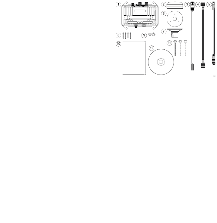
2.4 Parts supplied
1. AIS700
2. GNSS antenna
3. Power/data cable 2m (6.56 ft)
4. VHF Radio cable 1m (3.28 ft)
5. DeviceNet to SeaTalkng ® adaptor cable 1m (3.28 ft)
6. GNSS antenna gasket
7. GNSS antenna pole mount
8. Unit fixings (4 x No.8x19 self tapping screws)
9. M5 nut and washer (grounding)
10. Documentation
11. GNSS antenna fixings (3 x M3x40 stud and thumb
nut)
12. Software CD
Document and product information 11

12

Chapter 3: Installation
Chapter contents
• 3.1 Selecting a location on page 14
• 3.2 Mounting the AIS700 on page 15
• 3.3 Mounting the antenna on page 16
Installation 13
3.1 Selecting a location
Warning: Potential ignition
source
This product is NOT approved for use in
hazardous/flammable atmospheres. Do
NOT install in a hazardous/flammable
atmosphere (such as in an engine room or
near fuel tanks).
General location requirements
When selecting a location for your AIS700 it is important
to consider a number of factors.
•Water ingress — The AIS700 should be mounted
below decks. Although the AIS700 is waterproof, it is
good practice to locate it in a protected area away
from prolonged and direct exposure to rain and salt
spray.
•Ventilation — To ensure adequate airflow:
– Ensure that AIS700 is mounted in a compartment
of suitable size.
– Ensure that ventilation holes are not obstructed.
Allow adequate separation of all equipment.
•Electrical interference — Select a location that
is far enough away from devices that may cause
interference, such as motors, generators and radio
transmitters / receivers.
•Power supply — Select a location that is as close as
possible to the vessel’s DC power source. This will
help to keep cable runs to a minimum.
•Diagnostics — The AIS700 must be mounted in a
location where any diagnostics LEDs are easily visible.
•Mounting surface — Ensure the AIS700 is adequately
supported on a secure surface. Do not mount units or
cut holes in places which may damage the structure
of the vessel.
•Cabling — Ensure the AIS700 is mounted in a location
which allows proper routing, support and connection
of cables:
– Minimum bend radius of 100 mm (3.94 in) unless
otherwise stated.
– Use cable clips to prevent stress on connectors.
– If your installation requires multiple ferrites to be
added to a cable then additional cable clips should
be used to ensure the extra weight of the cable is
supported.
GNSS antenna location requirements
The AIS700 includes a built-in GNSS receiver and is
supplied with a GNSS antenna which must be installed
in accordance with the instructions provided. Do NOT
connect any other GNSS antenna other than that
supplied.
The GNSS antenna can be mounted either on a flat
horizontal surface or on a suitable pole.
• If you intend to surface mount the antenna, ensure you
have access to the underside of the mounting surface.
• If you intend to pole-mount the antenna, the pole
needs to have a 1 inch 14 TPI thread.
Important:
The GNSS antenna must be mounted in a location
that provides a good direct line of site to the entire
sky, around the horizon.
Ensure that the selected mounting location is:
• Open and clear of any obstructions (such as masts,
search lights, or other structures) that could block
line-of-sight to the sky.
• As low as possible, to keep the antenna as stable
as possible. The more stable the antenna, the more
effectively it will track satellites and provide stable
data.
• As far as possible (at least 1 m (3 ft)) from other
antennae and electronic equipment.
Do NOT mount the antenna:
• In any area where it could be stepped on or tripped
over.
• Up a mast. This will cause the antenna to swing and
give significant errors in position data.
• In the direct path of a Radar beam.
EMC installation guidelines
Raymarine® equipment and accessories conform to
the appropriate Electromagnetic Compatibility (EMC)
regulations, to minimize electromagnetic interference
between equipment and minimize the effect such
interference could have on the performance of your
system
Correct installation is required to ensure that EMC
performance is not compromised.
Note:
In areas of extreme EMC interference, some slight
interference may be noticed. Where this occurs the
AIS700 and the source of the interference should be
separated by a greater distance.
For optimum EMC performance we recommend that
wherever possible:
• Raymarine® equipment and cables connected to it are:
– At least 1 m (3 ft) from any equipment transmitting
or cables carrying radio signals e.g. VHF radios,
cables and antennas. In the case of SSB radios, the
distance should be increased to 2 m (7 ft).
– More than 2 m (7 ft) from the path of a Radar beam.
A Radar beam can normally be assumed to spread
20 degrees above and below the radiating element.
• The AIS700 is supplied from a separate battery from
that used for engine start. This is important to prevent
erratic behavior and data loss which can occur if the
engine start does not have a separate battery.
• Raymarine® specified cables are used.
• Cables are not cut or extended, unless doing so is
detailed in the installation instructions.
Note: Where constraints on the installation prevent
any of the above recommendations, always ensure
the maximum possible separation between different
items of electrical equipment, to provide the best
conditions for EMC performance throughout the
installation
14
Suppression ferrites
• Raymarine® cables may be pre-fitted or supplied with
suppression ferrites. These are important for correct
EMC performance. If ferrites are supplied separately
to the cables (i.e. not pre-fitted), you must fit the
supplied ferrites, using the supplied instructions.
• If a ferrite has to be removed for any purpose (e.g.
installation or maintenance), it must be replaced in the
original position before the product is used.
• Use only ferrites of the correct type, supplied by
Raymarine® or its authorized dealers.
• Where an installation requires multiple ferrites to be
added to a cable, additional cable clips should be
used to prevent stress on the connectors due to the
extra weight of the ferrites.
Connections to other equipment
Requirement for ferrites on non-Raymarine® cables.
If your AIS700 is to be connected to other equipment
using a cable not supplied by Raymarine®, a suppression
ferrite MUST always be attached to the end of the cable
near the AIS700.
RF interference
Certain third-party external electrical equipment can
cause Radio Frequency (RF) interference with GPS,
AIS or VHF devices if the external equipment is not
adequately insulated and emits excessive levels of
electromagnetic interference (EMI).
Some common examples of such external equipment
include LED spot or strip lights, and terrestrial TV tuners.
To minimize interference from such equipment:
• Keep it as far away from GPS, AIS or VHF devices as
possible.
• Ensure that any power cables for external equipment
are not entangled with the power or data cables for
GPS, AIS or VHF devices.
• Consider fitting one or more high frequency
suppression ferrites to the EMI-emitting device. The
ferrite(s) should be rated to be effective in the range
100 MHz to 2.5 GHz, and should be fitted to the power
cable and any other cables exiting the EMI-emitting
device, as close as possible to the position where the
cable exits the device.
Compass safe distance
To prevent potential interference with the vessel's
magnetic compasses, ensure an adequate distance is
maintained from the AIS700.
When choosing a suitable location for the AIS700 you
should aim to maintain the maximum possible distance
from any compasses. Typically this distance should be
at least 1 m (3 ft) in all directions. However for some
smaller vessels it may not be possible to locate the
AIS700 this far away from a compass. In this situation,
when choosing the installation location, ensure that the
compass is not affected by the AIS700 when it is in a
powered state.
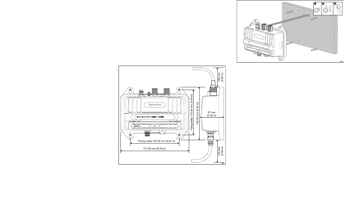
AIS700 dimensions
3.2 Mounting the AIS700
Before mounting the AIS700 ensure that you have:
• selected a suitable location (a clear, flat surface is
required).
• Identified the relevant cable connections and the
route that the cable will take.
1. Using the AIS700 as a guide, mark the location of the
mounting holes on the mounting surface.
2. Drill holes for the mounting fixings using a drill with
a suitable sized drill bit.
3. Screw the fixings approximately half way into the
holes in the mounting surface.
4. Place the AIS700 over the fixings screws and push
down to lock into position.
5. Fully tighten the screws.
6. Connect the necessary cables.
Installation 15
3.3 Mounting the antenna
To mount the antenna:
1. Select a suitable location for the antenna,
as described in the
GNSS antenna location
requirements
section.
2. Mount your antenna using either the
Surface
mounting
or
Pole mounting
procedure, as
appropriate.
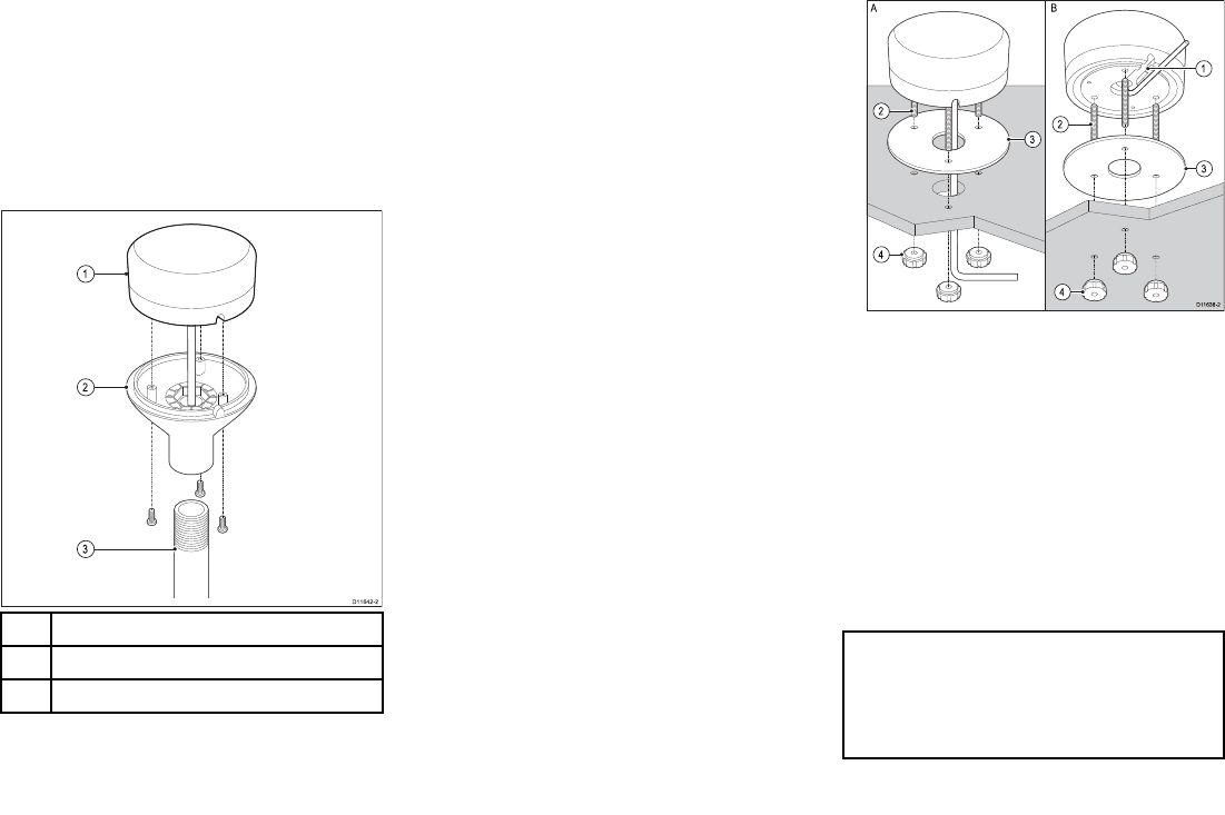
Pole mounting
If you want to pole-mount the antenna, obtain a pole of
suitable length with a 1 inch 14 TPI thread.
1GNSS antenna
2Pole mount adaptor
3Mounting pole (not supplied)
1. Ensuring that the
GNSS antenna location
requirements
are met, securely attach the pole to
a suitable, secure point.
2. Remove and retain the screws securing the antenna
to the pole mount adaptor, then separate these two
items.
3. Screw the pole mount adaptor fully onto the pole
and ensure it is secure.
4. Feed the antenna cable through the center of the
pole mount adaptor and then down through the
center of the mounting pole.
5. Ensuring you do not trap the cable, place the antenna
on the pole mount adaptor so the screw holes are
aligned, then secure the antenna with the 3 screws
removed during step 2.
Surface mounting
When surface mounting the antenna, you can route the
cable either centrally (Option A) or from the side of the
antenna (Option B).
1. Remove the 3 screws securing the antenna to its
pole mount adaptor, then remove the adaptor from
the antenna.
2. Using the supplied mounting template, mark and drill
the mounting holes.
• OPTION A: If the cable is going to pass through the
mounting surface, drill a 19 mm (0.75 in.) center
hole for the cable.
• OPTION B: If the cable is to be routed from the side
of the antenna (i.e. above the mounting surface),
remove the piece of plastic covering the end of
the cable channel and route the cable through
the channel (1). Incorrect cable routing can cause
damage to the cable.
3. Screw the supplied mounting studs (2) into the
underside of the antenna.
4. Stick the supplied gasket (3) to the mounting surface,
ensuring that the holes on the gasket correspond
with the drilled holes.
5. Route the cable as follows:
• For Option A, feed the cable down through the
center hole.
• For Option B, route the cable along the cable
channel.
6. Carefully place the antenna so the mounting studs
pass through the holes in the mounting surface.
7. Secure the antenna to the surface using the supplied
thumb nuts (4).
Note:
• The thumb nuts supplied with your product may
differ slightly from those shown in the illustration.
• Only use the studs and thumb nuts supplied with
the antenna.
16

Chapter 4: Connections
Chapter contents
• 4.1 Connections overview on page 18
• 4.2 USB connection on page 20
• 4.3 Power connection on page 20
• 4.4 NMEA 2000 / SeaTalkng ® connection on page 22
• 4.5 NMEA 0183 connection on page 23
• 4.6 GPS (GNSS) antenna connection on page 23
• 4.7 VHF antenna connection on page 24
• 4.8 VHF radio connection on page 24
• 4.9 Silent mode switch connection on page 24
Connections 17
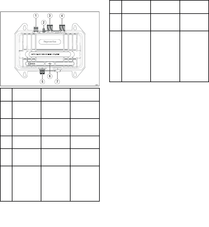
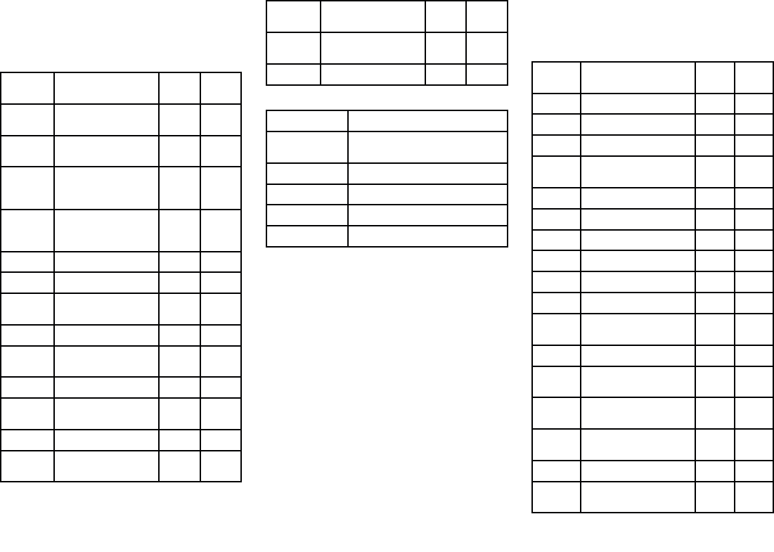
4.1 Connections overview
Connection Connects to:
Suitable
cables:
1GNSS
connection
GNSS
antenna
GNSS
antenna’s
fitted cable
2 Grounding
earth stud
connection
Vessel RF
ground only
Refer to the
Grounding
section.
3To Antenna
connection
VHF antenna VHF antenna
cable
4 To VHF
connection
VHF Radio The supplied
VHF radio
cable
5NMEA 2000
/ SeaTalkng ®
connection
NMEA
2000 or
SeaTalkng ®
backbone.
The supplied
DeviceNet to
SeaTalkng ®
adaptor
cable or a
DeviceNet
spur cable
Connection Connects to:
Suitable
cables:
6 USB
connection
Personal
computer
(PC)
Micro B USB
cable
7 Power
and data
connection
• 12/24 V
dc power
supply
• NMEA
0183
devices
• Silent
mode
switch
The supplied
Power/data
cable
18
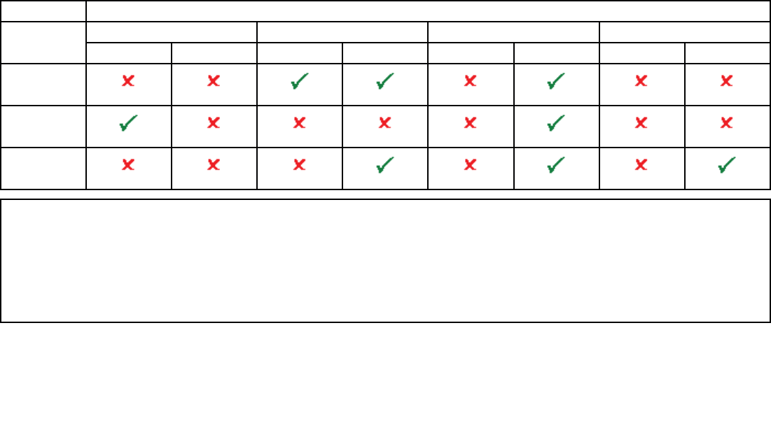
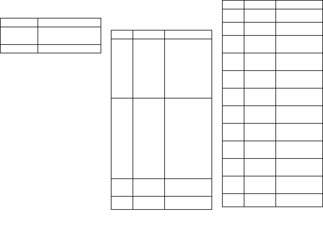
Data connections matrix
The following table details the types of data that can be exchanged using the various combinations of data connections NMEA 0183 (Low / High baud rate), NMEA 2000 /
SeaTalkng ®, and USB).
It is important to choose the right combination of connections in order to exchange the types of data you require.
As an example of how to use the table below, you can see that you can feed GNSS data into the AIS700 via a NMEA 0183 port configured for low baud rate (4,800), and then output it
along with AIS data to the other NMEA 0183 port configured for high baud rate (38,400).
When data is input on one NMEA 0183 port it is output on the other NMEA 0183 port, you cannot receive and send data on the same NMEA 0183 port.
INPUTS OUTPUTS
NMEA 0183 (4,800) NMEA 0183 (38,400) NMEA 2000,* / SeaTalkng ® USB
GNSS AIS GNSS AIS GNSS AIS GNSS AIS
NMEA 0183
(4,800)
GNSS
NMEA 0183
(38,400)
GNSS
NMEA 2000 /
SeaTalkng ®
GNSS
Important:
To avoid potential data conflicts or loops multiple network protocols should not be connected to the same device i.e.:
• Do NOT connect the AIS700 to a MFD using NMEA 0183 and SeaTalkng ®/ NMEA 2000 connections at the same time.
• Do NOT connect the AIS700 to a VHF Radio using NMEA 0183 and SeaTalkng ®/ NMEA 2000 connections at the same time.
• Do NOT connect the AIS700 to a PC using NMEA 0183 and USB connections at the same time.
• If you are connecting to an AIS capable VHF Radio, you must disable the VHF Radio’s AIS function first. Refer to your Radio’s documentation for details on disabling
the AIS function.
Connections 19
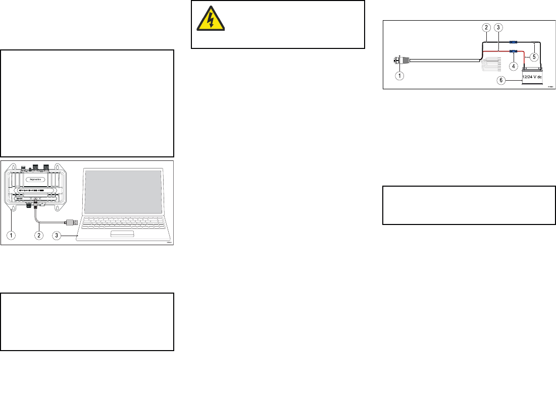
4.2 USB connection
Before using your AIS700 you must configure the unit
using the supplied proAIS2 software via a PC connected
to the USB connection.
Important:
In the United States of America, it is a violation of the
rules of the Federal Communications Commission to
input an MMSI that has not been properly assigned
to the end user or to otherwise input any inaccurate
data in this device. The MMSI and Static Data
must be entered only by a Raymarine dealer or
other appropriately qualified installer of marine
communications equipment on board vessels.
Ensure you check the regulations for your location to
ensure you are allowed to configure MMSI data on
your unit.
1. AIS700
2. USB Micro-B to type A cable (not supplied)
3. PC (personal computer) running proAIS2
Note:
• The PC USB connection will provide power to the
unit to enable configuration prior to installation.
• Refer to Chapter 5 Set up
for details on configuring your AIS700.
Warning: USB device power
Do NOT connect any device to the product’s
USB connection that requires an external
power source.
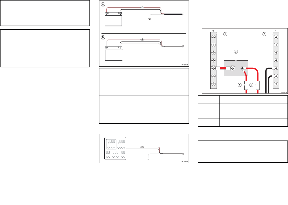
4.3 Power connection
1. Power/data cable (supplied)
2. Power supply – (Negative) Black wire
3. Power supply + (Positive) Red wire
4. Suitable waterproof connection (not supplied)
5. Power cable extension to vessel’s circuit
breaker/power source
6. Power source (12/24 V dc)
Note: It is recommended that the power is supplied
via a circuit breaker or that the unit is protected using
a 3 A inline fuse connected to the Red (+) positive
wire.
Power distribution
Recommendations and best practice.
• The product is supplied with a power cable. Only use
the power cable supplied with the product. Do NOT
use a power cable designed for, or supplied with, a
different product.
• Refer to the
Power connection
section for more
information on how to identify the wires in your
product’s power cable, and where to connect them.
• See below for more information on implementation for
some common power distribution scenarios.
20
Important:
When planning and wiring, take into consideration
other products in your system, some of which (e.g.
sonar modules) may place large power demand
peaks on the vessel’s electrical system.
Note:
The information provided below is for guidance only,
to help protect your product. It covers common
vessel power arrangements, but does NOT cover
every scenario. If you are unsure how to provide
the correct level of protection, please consult an
authorized Raymarine dealer or a suitably qualified
professional marine electrician.
Implementation — direct connection to battery
• The power cable supplied with your product may
be connected directly to the vessel's battery, via a
suitably rated fuse or breaker.
• The power cable supplied with your product may NOT
include a separate drain wire. If this is the case, only
the power cable’s red and black wires need to be
connected.
• If the supplied power cable is NOT fitted with an inline
fuse, you MUST fit a suitably rated fuse or breaker
between the red wire and the battery’s positive
terminal.
• Refer to the inline fuse ratings provided in the
product’s documentation.
• If you need to extend the length of the power cable
supplied with your product, ensure you observe the
dedicated
Power cable extensions
advice provided in
the product’s documentation.
ABattery connection scenario A: suitable for a
vessel with a common RF ground point. In
this scenario, if your product’s power cable is
supplied with a separate drain wire then it should
be connected to the vessel’s common ground
point.
BBattery connection scenario B: suitable for
a vessel without a common grounding point.
In this case, if your product’s power cable is
supplied with a separate drain wire then it should
be connected directly to the battery’s negative
terminal.
Implementation — connection to distribution panel
• Alternatively, the supplied power cable may be
connected to a suitable breaker or switch on the
vessel's distribution panel or factory-fitted power
distribution point.
• The distribution point should be fed from the vessel’s
primary power source by 8 AWG (8.36 mm2) cable.
• Ideally, all equipment should be wired to individual
suitably-rated thermal breakers or fuses, with
appropriate circuit protection. Where this is not
possible and more than 1 item of equipment shares a
breaker, use individual in-line fuses for each power
circuit to provide the necessary protection.
1Positive (+) bar
2Negative (-) bar
3 Circuit breaker
4 Fuse
• In all cases, observe the recommended breaker / fuse
ratings provided in the product’s documentation.
Important:
Be aware that the suitable fuse rating for the thermal
breaker or fuse is dependent on the number of
devices you are connecting.
Power cable extension
If you need to extend the length of the power cable
supplied with your product, ensure you observe the
following advice:
• The power cable for each unit in your system should
be run as a separate, single length of 2-wire cable
Connections 21
from the unit to the vessel's battery or distribution
panel.
• For power cable extensions, it is recommended that a
minimum wire gauge of 16 AWG (1.31 mm2). For cable
runs longer than 15 meters, you may need to consider
a thicker wire gauge (e.g. 14 AWG (2.08 mm2), or 12
AWG (3.31 mm2) ).
• An important requirement for all lengths of power
cable (including any extension) is to ensure that there
is a continuous minimum voltage of 10.8 V at the
product’s power connector, with a fully flat battery at
11 V.
Important: Be aware that some products in your
system (such as sonar modules) can create voltage
peaks at certain times, which may impact the voltage
available to other products during the peaks.
Grounding
Ensure that you observe the separate grounding advice
provided in the product’s documentation.
More information
It is recommended that best practice is observed in all
vessel electrical installations, as detailed in the following
standards:
• BMEA Code of Practice for Electrical and Electronic
Installations in Boats
• NMEA 0400 Installation Standard
• ABYC E-11 AC & DC Electrical Systems on Boats
• ABYC A-31 Battery chargers and Inverters
• ABYC TE-4 Lightning Protection
Grounding
The AIS700 includes a dedicated grounding point to
reduce potential damage caused by near lightning
strikes.
The Grounding point should be connected to your
vessel’s RF ground. Do NOT connect to any point that is
connected to your vessel’s 0V Negative battery terminal.
1. M5 Nut (supplied)
2. M5 Shakeproof washer (supplied)
3. Grounding strap connected to vessel RF ground
(not supplied)
4. Grounding stud
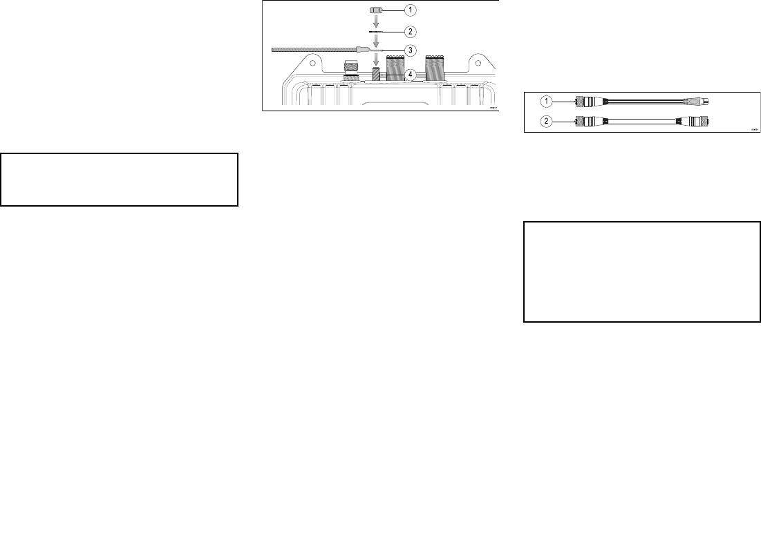
4.4 NMEA 2000 / SeaTalkng ®
connection
The AIS700 can transmit data to devices connected on
SeaTalkng ® or NMEA 2000 CAN bus networks. The
AIS700 is connected using the DeviceNet connector
located on the bottom of the unit.
1. Use the supplied DeviceNet to SeaTalkng ® adaptor
cable to connect your AIS700 to an available spur
connection on a SeaTalkng ® backbone.
2. Alternatively you can connect your AIS700 to a
NMEA 2000 backbone using a standard DeviceNet
cable (not supplied).
Note:
1. The AIS700 must be connected to a correctly
terminated backbone. You cannot connect your
AIS700 directly to a MFD.
2. Refer to the instructions supplied with your
SeaTalkng ® / NMEA 2000 device for details on
creating a backbone.
22
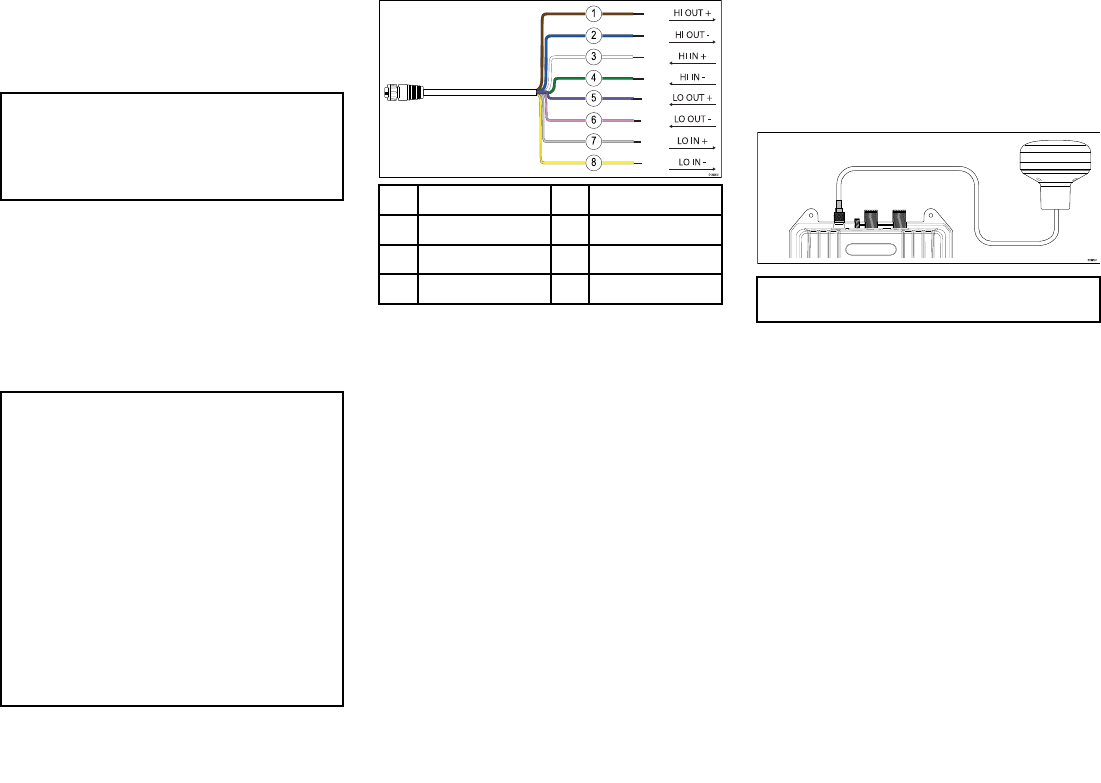
4.5 NMEA 0183 connection
The AIS700 can transmit data to devices connected via
NMEA 0183. The AIS700 is connected using the NMEA
0183 wires located on the Power/data cable.
Note: Whilst it is possible to output both AIS and
GNSS data, it is NOT recommended that you output
GNSS data to external devices as this can cause data
conflicts and / or performance issues. The ability
to output GNSS data is intended for diagnostics
purposes only.
The AIS700 includes 2 bidirectional NMEA 0183 ports.
The baud rate for each port can be configured using
the supplied proAIS2 software. Both ports can be
multiplexed which enables any data provided to one
port to be combined with AIS data and output on the
other port.
Typically port 1 is connected to an MFD and configured
for 38,400 baud rate, the baud rate required for AIS
data transfer. Port 2 is connected to a Heading sensor
or other NMEA 0183 device and configured for 4,800
baud rate.
Important:
To avoid potential data conflicts or loops multiple
network protocols should not be connected to the
same device i.e.:
• Do NOT connect the AIS700 to a MFD using NMEA
0183 and SeaTalkng ®/ NMEA 2000 connections
at the same time.
• Do NOT connect the AIS700 to a VHF Radio
using NMEA 0183 and SeaTalkng ®/ NMEA 2000
connections at the same time.
• Do NOT connect the AIS700 to a PC using NMEA
0183 and USB connections at the same time.
• If you are connecting to an AIS capable VHF Radio,
you must disable the VHF Radio’s AIS function first.
Refer to your Radio’s documentation for details on
disabling the AIS function.
The NMEA 0183 connection wires on the power/data
cable are identified below.
1Brown (HI OUT +) 2Blue (HI OUT –)
3White (HI IN +) 4Green (HI IN –)
5Purple (LO OUT +) 6Pink (LO OUT –)
7Gray (LO IN +) 8Yellow (LO IN –)
4.6 GPS (GNSS) antenna
connection
Connect the supplied GNSS antenna to your AIS700
using the GNSS antenna connection. The antenna
is fitted with a 10m (33ft) cable for connecting to the
AIS700.
Note: Do NOT connect any other antenna than the
one supplied with your AIS700.
If the antenna is not connected or connected incorrectly
then your AIS700 will operate in Silent mode, the AIS700
will not transmit but will still receive.
Connections 23
4.7 VHF antenna connection
Connect a VHF antenna (not supplied) to your AIS700
using the VHF antenna connection.
VHF antenna requirements
The VHF antenna should meet the following
requirements:
Frequency band 156.025 MHz to 162.025
MHz
VSWR (Voltage Standing
Wave Ratio
should not exceed 2:1
Impedance 50 Ohm
Gain 3dBi Max
Connector PL-259
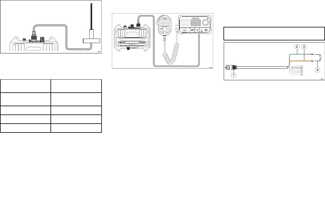
4.8 VHF radio connection
For systems that include a VHF DSC radio you can
share the VHF antenna by connecting your Radio’s VHF
antenna connection to the VHF Radio connection on
your AIS700 and then connecting your VHF antenna to
the AIS700,s VHF antenna connection.
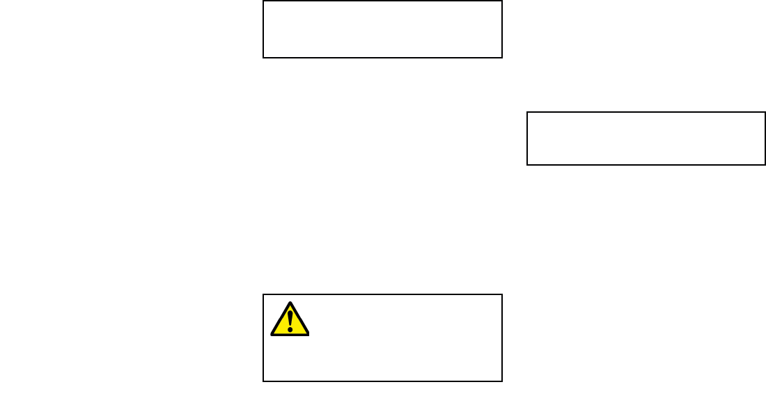
4.9 Silent mode switch
connection
In Silent mode your AIS700 will stop transmitting position
data and operate as a receiver only. Silent mode can be
enabled using a connected MFD and by connecting a
switch to the relevant wires on the Power/data cable.
Please refer to your MFD’s operation instructions for
details on enabling silent mode.
Note: A silent mode switch will override an MFD’s
Silent mode setting.
1. Power/data cable (supplied)
2. Light Green wire
3. Orange wire
4. Switch (not supplied)
Crimp or solder wire connections and ensure suitable
insulation from water ingress.
24

Chapter 5: Set up
Chapter contents
• 5.1 Configure before use on page 26
• 5.2 Obtain MMSI (Maritime Mobile Service Identity) number on page 26
• 5.3 Configuration on page 26
• 5.4 Software updates on page 27
Set up 25
5.1 Configure before use
Before use this product must be correctly configured
using a personal computer and the supplied proAIS2
software. Incorrect configuration can cause erroneous
data and prevent your product from transmitting.
5.2 Obtain MMSI (Maritime
Mobile Service Identity) number
Before commencing installation ensure you have
obtained a MMSI number for your vessel.
A MMSI is a 9 digit number which is sent over a radio
frequency channel in order to identify the originating
vessel/station. If your vessel already has a MMSI number
(used for a VHF DSC radio) then the same MMSI number
must be used to program your AIS700.
Note:
If a MMSI number is not entered, the AIS700 can
only be used in Silent Mode and will operate as a
receiver only.
In the United States of America, the MMSI and Static
Data must be entered only by a Raymarine® dealer
or other appropriately qualified installer of marine
communications equipment on board vessels.
The user is NOT authorized to do this.
In some areas, a radio operator licence is required
before a MMSI number will be issued. You can request
a MMSI number from same agency that issues radio or
Ship Radio licences in your area.
In Europe and other parts of the world outside of the
United States of America, the MMSI and Static data can
be set up by the user.
For further details, refer to the relevant
Telecommunications Regulatory Body for your
area.
Refer to Appendix A MMSI Regulatory bodies and
application submissions
for a list of contacts for obtaining MMSI numbers for
some areas.
Warning: MMSI entry
You can only enter a MMSI number once, if
you enter the number incorrectly or need
to change your MMSI number, the unit will
require re-programming by an authorized
Raymarine® dealer.
5.3 Configuration
The AIS700 can be configured before or after installation
using a personal computer, USB Micro-B cable and the
supplied proAIS2 software.
The manner in which configuration is carried out
depends on the legal requirements of your geographical
location.
USA
In the USA, it is a legal requirement that the configuration
is performed by a suitable dealer.
You can use the supplied proAIS2 PC software, to check
the vessel data programmed into your AIS700. If this
information is incorrect please contact your Raymarine
dealer.
Areas outside of USA
In areas outside of the USA, use the supplied proAIS2
PC software to configure your AIS700.
Note: If configuring after installation ensure any
MFDs on the same network are switched off first,
otherwise you will not be able to correctly configure
your AIS700.
The following vessel related static data should be
configured:
• MMSI number
• Vessel name
• Vessel call sign
• Vessel dimensions including AIS GNSS antenna
location
• Vessel type
A valid 9 digit MMSI number must be entered. Invalid
numbers will not be accepted. All other fields (i.e. vessel
type, name etc.) are optional.
26
Installing proAIS2 and USB drivers
Before connecting the AIS unit to a PC the proAIS2
application and USB drivers must be installed. To install
follow the steps below:
1. Insert the supplied CDROM and navigate to the
proAIS2 folder.
If you do not have an optical media drive such
as a CDROM then the proAIS2 software can also
be downloaded from the Raymarine® website:
www.raymarine.com/software
2. Double click on the setup.exe file to launch the
installer.
3. Follow the on screen installation instructions,
ensuring that the option to install USB drivers is
selected when presented.
4. Once installed the AIS unit can be connected to the
PC. The USB drivers will be installed automatically
and the AIS unit will appear as a new COM port
device.
5. Launch proAIS2 by navigating to the proAIS2 folder
accessible from the start menu.
6. The proAIS2 user manual is available from the help
menu from within the application.
Configuring using proAIS2
Important:
In the United States of America, it is a violation of the
rules of the Federal Communications Commission to
input an MMSI that has not been properly assigned
to the end user or to otherwise input any inaccurate
data in this device. The MMSI and Static Data
must be entered only by a Raymarine dealer or
other appropriately qualified installer of marine
communications equipment on board vessels.
Ensure you check the regulations for your location to
ensure you are allowed to configure MMSI data on
your unit.
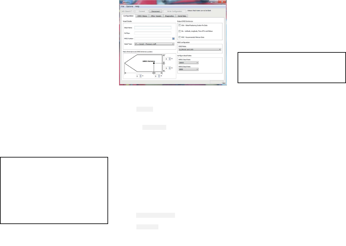
With the proAIS2 software open on your PC:
1. Select the AIS device from the drop down list at the
top of the page.
2. Click Connect.
3. Enter your vessel’s details, including MMSI in the
relevant fields.
4. Select a Vessel Type appropriate for your vessel
from the drop down list.
5. Ensure that the built-in GNSS receiver is not
outputting sentences (i.e. ensure GGA, GLL and RMC
boxes are not ticked).
The GNSS receiver built-in to the AIS700 is intended
to provide GNSS data to the AIS unit only, outputting
this data can cause data conflicts. The ability to
output these sentences is intended for diagnostics
purposes only.
6. Enter your vessel’s dimensions and GNSS antenna
location in the relevant fields.
7. If required set the baud rate for your NMEA 0183
ports.
8. Click Write Configuration to save your configuration
settings.
9. Click Disconnect.
5.4 Software updates
You can update the software on the AIS700 using a
Raymarine MFD running LightHouse™ 2 or LightHouse™
3 operating system connected using SeaTalkng ® or
NMEA 2000.
Please refer to the operation instructions for your MFD
/ operating system for details on how to perform a
software update.
Note:
You can also perform software updates using a
PC and the USB connection, please refer to the
Raymarine® website for software and instructions:
www.raymarine.com/software
Set up 27

28

Chapter 6: Troubleshooting
Chapter contents
• 6.1 LED Status indicator on page 30
• 6.2 Troubleshooting on page 30
Troubleshooting 29
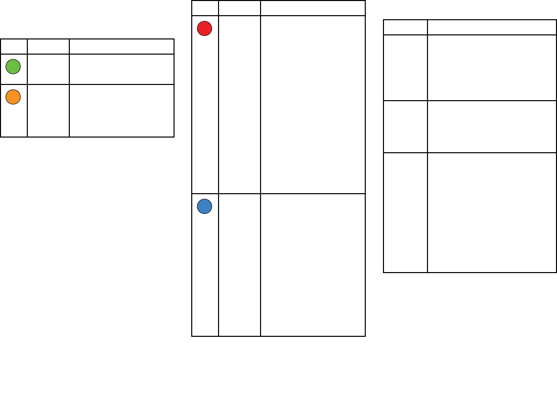
6.1 LED Status indicator
The LED status indicator on the transceiver provides an
indication of product status.
LED Color Status
Green Transceiver is operating
normally and has transmitted
at least 1 position report.
Amber Transceiver is not transmitting.
• Wait at least 30 minutes to
check that a ‘Quiet time’ has
not been requested by the
local authority.
LED Color Status
Red Transceiver fault.
• Check MMSI number
and static data has been
correctly configured.
• Check GNSS antenna is
properly connected and has
a clear unobstructed view of
the sky.
• Check the VHF antenna is
properly connected and is
not short circuiting to the
vessel structure.
• Check that power supply is
at the correct voltage (12 V
dc or 24 V dc).
• Excessive difference
between Heading from
an input device and COG.
Blue Transceiver is running in silent
mode (not transmitting), if you
want to disable silent mode:
• Check the AIS Silent mode
setting on your MFD.
• Check the position of the
dedicated Silent mode
switch, if fitted (The switch
will override the MFD
setting).
• Where no dedicated switch
is fitted, check that the Light
Green and Orange wires on
the Power/data cable are
not shorting together.
6.2 Troubleshooting
Problem Action required
No power • Check the power supply is properly
connected.
• Check the power supply voltage is
correct (12 V dc or 24 V dc)
• Check relevant fuses have not blown
or circuit breaker has not tripped.
AIS con-
figuration,
static data
is not be-
ing saved.
• Switch off all associated MFDs, then
retry configuration.
• Disconnect all connections then
connect only the USB cable to a PC
and retry configuration.
AIS hard-
ware not
detected
by MFD
(No AIS
symbol
shown on
Home-
screen)
• Check SeaTalkng ® / NMEA 2000 or
NMEA 0183 connection and ensure
proper connection.
• When connected using NMEA 0183
ensure the port used to connect
your transceiver to your MFD is set
to 38,400 baud rate.
• Ensure the MFD is either; connected
directly to the same CAN bus
network as your AIS transceiver, or
the same SeaTalkhs ® network as the
MFD that is connected to the same
CAN bus as your transceiver.
30

Problem Action required
No AIS tar-
gets/data
shown
on MFD
(AIS sym-
bol shown
on Home-
screen)
• Check MMSI number and static data
has been correctly configured.
• Check the VHF antenna is properly
connected and is not short circuiting
to the vessel structure.
• When connected using NMEA 0183
ensure the port used to connect
your transceiver to your MFD is set
to 38,400 baud rate.
• AIS Layer not enabled on MFD.
• MFD set to display Dangerous or
Buddy targets only and none are in
range of your vessel.
• No AIS equipped vessels in range.
Erratic or
conflicting
data
• More than 1 AIS unit is connected
and operating.
• NMEA 0183 and SeaTalkng ® / NMEA
2000 connected at the same time.
Troubleshooting 31

32

Chapter 7: Technical specification
Chapter contents
• 7.1 AIS700 technical specification on page 34
Technical specification 33

7.1 AIS700 technical
specification
Power specification
Supply voltage 12 V dc / 24 V dc
Operating voltage range 9.6 V dc to 31.2 V dc
Power consumption <3 W
Fuse rating 3 A
LEN (Load Equivalency
Number)
1
Environmental specification
Operating temperature
range
-15°C to +55°C (+5°F to
+131°F)
Storage temperature
range
-20°C to +75°C (-4°F to
167°F)
Humidity 93% at 40°C
Waterproofing IPx6, IPx7
AIS specification
Transmitter x 1
Receiver x 2
Operating frequency
range
• Transmitting:
156.0MHz to 162.025
MHz
• Receiving: 156.0MHz
to 174.0 MHz
Channel spacing 25 KHz
AIS performance 5 W SOTDMA
GNSS receiver specification
Channels 72
Cold start acquisition 26s nominal
Position source • GPS
• GLONASS
External connections
VHF antenna connector
type
SO-239 co-axial
VHF radio connector
type
SO-239 co-axial
GNSS antenna
connector type
50Ω TNC co-axial
SeaTalkng ® / NMEA
2000 connector type
5 way DeviceNet male
Power and NMEA 0183 12 way bare ended wires
NMEA 0183 port 1 (MFD
connection)
NMEA 0183 HS (IEC
61162–1) compliant,
bi-directional, RS422
levels, 4 wire interface
(differential signalling),
configurable baud rate
NMEA 0183 port 2
(Instrument connection)
NMEA 0183 (IEC 61162–1)
compliant, bi-directional,
RS422 levels, 4 wire
interface (differential
signalling), configurable
baud rate
Power 2 way bare ended wires
Silent mode switch 2 way bare ended wires
USB Micro-B
Earth stud Threaded stud (nut and
washer supplied)
34

Chapter 8: Technical support
Chapter contents
• 8.1 Raymarine product support and servicing on page 36
• 8.2 Learning resources on page 37
Technical support 35

8.1 Raymarine product support
and servicing
Raymarine provides a comprehensive product support
service, as well as warranty, service, and repairs. You
can access these services through the Raymarine
website, telephone, and e-mail.
Product information
If you need to request service or support, please have
the following information to hand:
• Product name.
• Product identity.
• Serial number.
• Software application version.
• System diagrams.
You can obtain this product information using the menus
within your product.
Servicing and warranty
Raymarine offers dedicated service departments for
warranty, service, and repairs.
Don’t forget to visit the Raymarine website to
register your product for extended warranty benefits:
http://www.raymarine.co.uk/display/?id=788.
Region Tele-
phone
E-mail
United
Kingdom
(UK), EMEA,
and Asia
Pacific
+44
(0)1329
246
932
emea.service@rayma-
rine.com
United
States (US)
+1 (603)
324
7900
rm-usrepair@flir.com
Web support
Please visit the “Support” area of the Raymarine website
for:
•Manuals and Documents —http://www.rayma-
rine.com/manuals
•FAQ / Knowledgebase —http://www.rayma-
rine.com/knowledgebase
•Technical support forum —http://forum.rayma-
rine.com
•Software updates —http://www.raymarine.com/soft-
ware
Telephone and e-mail support
Region Tele-
phone
E-mail
United
Kingdom
(UK), EMEA,
and Asia
Pacific
+44 (0
)1329
246
777
support.uk@rayma-
rine.com
United States
(US)
+1
(603)
324
7900
(Toll-
free:
+800
539
5539)
support@raymarine.com
Australia and
New Zealand
+61 2
8977
0300
aus.support@rayma-
rine.com
(Raymarine subsidiary)
France +33
(0)1 46
49 72
30
support.fr@rayma-
rine.com
(Raymarine subsidiary)
Germany +49
(0)40
237
808 0
support.de@rayma-
rine.com
(Raymarine subsidiary)
Region Tele-
phone
E-mail
Italy +39 02
9945
1001
support.it@rayma-
rine.com
(Raymarine subsidiary)
Spain +34 96
2965
102
sat@azimut.es
(Authorized Raymarine
distributor)
Netherlands +31
(0)26
3614
905
support.nl@rayma-
rine.com
(Raymarine subsidiary)
Sweden +46
(0)317
633
670
support.se@rayma-
rine.com
(Raymarine subsidiary)
Finland +358
(0)207
619
937
support.fi@rayma-
rine.com
(Raymarine subsidiary)
Norway +47
692 64
600
support.no@rayma-
rine.com
(Raymarine subsidiary)
Denmark +45
437
164 64
support.dk@rayma-
rine.com
(Raymarine subsidiary)
Russia +7 495
788
0508
info@mikstmarine.ru
(Authorized Raymarine
distributor)
36

8.2 Learning resources
Raymarine has produced a range of learning resources
to help you get the most out of your products.
Video tutorials
Raymarine official channel on
YouTube:
•http://www.youtube.com/user/R-
aymarineInc
Video Gallery:
•http://www.rayma-
rine.co.uk/view/?id=2679
Product Support videos:
•http://www.rayma-
rine.co.uk/view/?id=4952
Note:
• Viewing the videos requires a device with an
Internet connection.
• Some videos are only available in English.
Training courses
Raymarine regularly runs a range of in-depth training
courses to help you make the most of your products.
Visit the Training section of the Raymarine website for
more information:
•http://www.raymarine.co.uk/view/?id=2372
FAQs and Knowledge Base
Raymarine has produced an extensive set of FAQs and
a Knowledge Base to help you find more information
and troubleshoot any issues.
•http://www.raymarine.co.uk/knowledgebase/
Technical support forum
You can use the Technical support forum to ask a
technical question about a Raymarine product or to find
out how other customers are using their Raymarine
equipment. The resource is regularly updated with
contributions from Raymarine customers and staff:
•http://forum.raymarine.com
Technical support 37

38

Chapter 9: Spares and accessories
Chapter contents
• 9.1 Spares and accessories on page 40
• 9.2 SeaTalk ng® cables and accessories on page 40
Spares and accessories 39
9.1 Spares and accessories
The following spares are available:
Part number Description
R62241 GNSS passive antenna with 10
m (32.8 ft) coaxial cable (for AIS
transceivers only)
R32162 2 m (6.56 ft) Power/data cable
9.2 SeaTalk ng® cables and
accessories
SeaTalk ng cables and accessories for use with
compatible products.
Part No Description Notes
T70134 SeaTalk ng
starter kit
Includes:
• 1 x 5 Way connector
(A06064)
• 2 x Backbone
terminator (A06031)
• 1 x 3 m (9.8 ft) spur
cable (A06040)
• 1 x Power cable
(A06049)
A25062 SeaTalk ng
Backbone Kit
Includes:
• 2 x 5 m (16.4 ft)
Backbone cable
(A06036)
• 1 x 20 m (65.6 ft)
Backbone cable
(A06037)
• 4 x T-piece
(A06028)
• 2 x Backbone
terminator (A06031)
• 1 x Power cable
(A06049)
A06038 SeaTalk ng
0.4 m (1.3 ft)
spur
A06039 SeaTalk ng 1 m
(3.3 ft) spur
Part No Description Notes
A06040 SeaTalk ng 3 m
(9.8 ft) spur
A06041 SeaTalk ng 5 m
(16.4 ft) spur
A06042 SeaTalk ng 0.4
m (1.3 ft) elbow
spur
A06033 SeaTalk ng
0.4 m (1.3 ft)
backbone
A06034 SeaTalk ng
1 m (3.3 ft)
backbone
A06035 SeaTalk ng
3 m (9.8 ft)
backbone
A06036 SeaTalk ng 5
m (16.4 ft)
backbone
A06068 SeaTalk ng 9
m (29.5 ft)
backbone
A06037 SeaTalk ng 20
m (65.6 ft)
backbone
A06043 SeaTalk ng to
bare ends 1 m
(3.3 ft) spur
A06044 SeaTalk ng to
bare ends 3 m
(9.8 ft) spur
A06049 SeaTalk ng
Power cable
40

Part No Description Notes
A06031 SeaTalk ng
Terminator
A06028 SeaTalk ng
T-piece
Provides 1 x spur
connection
A06064 SeaTalk ng
5–way
connector
Provides 3 x spur
connections
A06030 SeaTalk ng
backbone
extender
E22158 SeaTalk to
SeaTalk ng
converter kit
Allows the connection
of SeaTalk devices to
a SeaTalk ng system.
A80001 SeaTalk ng
Inline
terminator
Provides direct
connection of a spur
cable to the end of a
backbone cable. No
T-piece required.
A06032 SeaTalk ng
Blanking plug
R12112 ACU / SPX
SeaTalk ng
spur cable 0.3
m (1.0 ft)
Connects an SPX
course computer or
an ACU to a SeaTalk ng
backbone.
A06047 SeaTalk (3 pin)
to SeaTalk ng
adaptor cable
0.4 m (1.3 ft)
A22164 SeaTalk to
SeaTalk ng
spur 1 m (3.3 ft)
spur
Part No Description Notes
A06048 SeaTalk2
(5 pin) to
SeaTalk ng
adaptor cable
0.4 m (1.3 ft)
A06045 DeviceNet
adaptor cable
(Female)
Allows the connection
of NMEA 2000 devices
to a SeaTalk ng system.
A06046 DeviceNet
adaptor cable
(Male)
Allows the connection
of NMEA 2000 devices
to a SeaTalk ng system.
E05026 DeviceNet
adaptor cable
(Female) to
bare ends.
Allows the connection
of NMEA 2000 devices
to a SeaTalk ng system.
E05027 DeviceNet
adaptor cable
(Male) to bare
ends.
Allows the connection
of NMEA 2000 devices
to a SeaTalk ng system.
Spares and accessories 41

42

Appendix A MMSI Regulatory
bodies and application
submissions
Country Regulatory Body Weblinks
UK Ofcom http://www.ofcom.org.uk
USA FCC (www.fcc.gov)•www.boatus.com
•www.seatow.com
•www.usps4mmsi.com
Canada Industry Canada www.ic.gc.ca
Australia Australian Maritime Safety Authority (AMSA) http://www.amsa.gov.au/mmsi/
Holland Agentschap Telecom www.agentschaptelecom.nl
Belgium Belgisch Instituut voor Postdiensten en
Telecommunicatie
www.bipt.be
Germany Bundesnetzagentur https://www.bundesnetzagentur.de/DE/Sachgebiete/Telekommunikation/Un-
ternehmen_Institutionen/Frequenzen/SpezielleAnwendungen/Seefunk/See-
funk-node.html
Denmark søfartsstyrelsen www.soefartsstyrelsen.dk
France Agence Nationale Des Fréquences https://www.anfr.fr/licences -et-autorisations/radiomaritime/
Italy Ministero dello sviluppo economico - Direzione
generale per le attività territoriali
http://www.sviluppoeconomico.gov.it/images/stories/documenti/mmsinew.pdf
Spain Ministero De Fomento https://www.fomento.gob.es/MFOM/LANG_CASTELLANO/DIRECCIONES_GEN-
ERALES/MARINA_MERCANTE/RADIOCOMUNICACIONES/MMSI/
Sweden PTS www.pts.se
Finland Viestintävirasto https://www.viestintavirasto.fi/en/spectrum/radiolicences/Boatingandnaviga-
tion.html
Iceland Post and telecom administration in Iceland www.pfs.is
New Zealand Radio Spectrum Management https://www.rsm.govt.nz/licensing/radio-operator-certificates-and-
callsigns?searchterm=MMSI
MMSI Regulatory bodies and application submissions 43

Country Regulatory Body Weblinks
Chile Directemar www.nauticentro.cl
Panama Autoridad Maritima de Panama www.amp.gob.pa/newside/spanish/puertos2/depima/ima.html
44
Appendix B NMEA 0183
supported sentences
The AIS700 supports the following NMEA 0183
sentences
Sen-
tence Description
Tran-
smit
Re-
ceive
ABK ABM/BBM
acknowledgement
•
ABM Addressed binary
message
•
ACA AIS channel
management
assignment
•
ACS AIS channel
management
information source
•
AIQ AIS query •
ACK Acknowledge alarm •
BBM Broadcast binary
message
•
HDT Heading true •
RST Equipment reset
command
• •
SSD Ship static data •
THS True heading and
status
•
TXT Text •
VDM AIS VHF data-link
message
•
Sen-
tence Description
Tran-
smit
Re-
ceive
VDO AIS VHF data-link
own-vessel report
•
VSD Voyage static data •
Sentences output by query (AIQ)
Sentence Description
ACA AIS channel management
assignment
SSD Ship static data
TXT Text
VER Version
VSD Voyage static data
Appendix C NMEA 2000
supported PGNs
The AIS700 supports the following PGNs.
PGN Description
Tran-
smit
Re-
ceive
59392 ISO Acknowledgement • •
59904 ISO Request • •
60928 ISO Address Claim • •
65240 ISO Commanded
Address
• •
126208 Request group function • •
126992 System time •
126993 Heartbeat •
126996 Product information • •
127250 Vessel heading •
129025 Position, rapid update •
129026 COG & SOG, rapid
update
•
129029 GNSS position data •
129038 AIS Class A position
report
•
129039 AIS Class B position
report
•
129040 AIS Class B extended
position report
•
129041 AIS AToN report •
129793 AIS UTC and date
report
•
NMEA 0183 supported sentences 45
PGN Description
Tran-
smit
Re-
ceive
129794 AIS class A static and
voyage related data
•
129795 AIS addressed binary
message
•
129796 AIS Acknowledge •
129797 AIS binary broadcast
message
•
129798 AIS SAR aircraft
position report
•
129801 AIS addressed SRM •
129802 AIS safety broadcast
binary message
•
129809 AIS class B CS static
data report part A
•
129810 AIS class B CS static
data report part B
•
Appendix D AIS overview
Your AIS700 uses digital radio signals to exchange
'real-time' information between vessels, shore based
stations, or aids to navigation (AToNs) on dedicated
VHF frequencies. This information is used to identify
and track vessels in the surrounding area and to provide
fast, automatic and accurate collision avoidance data.
Although AIS augments your Radar app by operating
in Radar blind spots and detecting smaller AIS-fitted
vessels, it does not replace your Radar, as it relies on
receiving transmitted AIS information and therefore
cannot detect objects such as landmasses, navigational
beacons or vessels not equipped with AIS.
Note:
NEVER assume that AIS is displaying information
from all vessels in the area, because:
• Not all vessels are fitted with AIS
• Although it is mandatory for larger commercial
vessels to carry AIS, it is not mandatory to use it.
AIS should be used only to augment Radar
information, not substitute it.
AIS limitation
Never assume that your AIS is detecting all vessels in
the area. Always exercise due prudence and do not use
AIS as a substitute for sound navigational judgement.
Classes of AIS
Class A transceivers
Class A AIS transceivers transmit and receive AIS
signals. AIS transceivers are currently mandatory on
all commercial vessels exceeding 300 tons that travel
internationally (SOLAS vessels).
The following information can be transmitted by a Class
A AIS system:
• Static data (Includes information such as MMSI
number, vessel name, vessel type, call sign, IMO
number, length, beam and GNSS antenna location).
• Voyage related data (Includes information such as
draft, cargo, destination, ETA and other relevant
information).
• Dynamic data (Includes information such as time
(UTC), ship’s position, COG, SOG, heading, rate of turn
and navigational status).
• Dynamic reports (Ship’s speed and status).
• Messages (Alarms and safety messages).
Remember that not all vessels will transmit all of the
information.
Class B transceivers
Class B AIS transceivers transmit and receive AIS
signals, but use a reduced set of data compared to Class
A (see
Data Summary
). A Class B AIS transceiver can be
fitted on any vessel not fitted with a Class A transceiver,
but is not mandatory aboard any vessel.
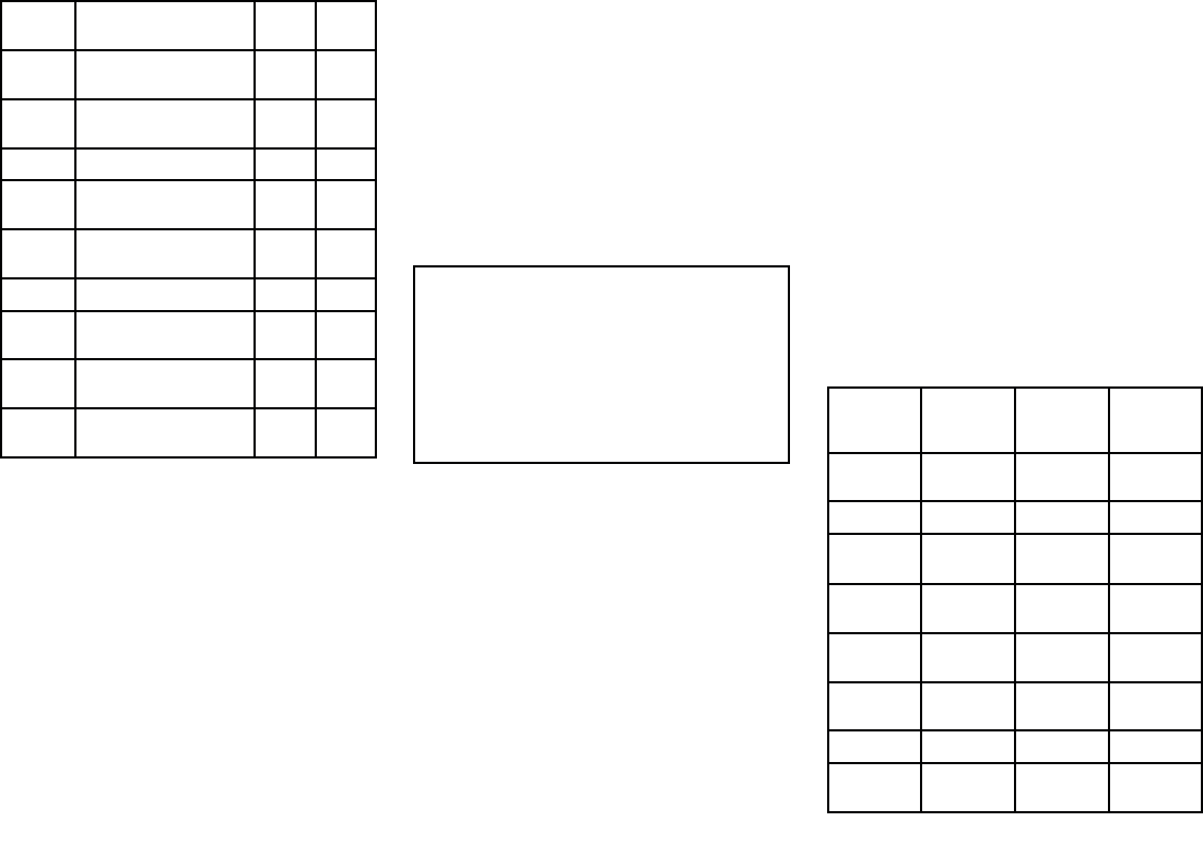
Data Summary
Data
Receiver
(receive)
Trans-
ceiver
(transmit)
Trans-
ceiver (re-
ceive)
Ship's
name
Yes Yes Yes
Type Yes Yes Yes
Call sign Yes Yes Yes
IMO
number
Yes No Yes
Length
and beam
Yes Yes Yes
Antenna
location
Yes Yes Yes
Draft Yes No Yes
Cargo In-
formation
Yes Yes Yes
46
Data
Receiver
(receive)
Trans-
ceiver
(transmit)
Trans-
ceiver (re-
ceive)
Destina-
tion
Yes No Yes
ETA Yes No Yes
Time Yes Yes Yes
Ship's
position
Yes Yes Yes
COG Yes Yes Yes
SOG Yes Yes Yes
Gyro
heading
Yes Yes* Yes
Rate of
turn
Yes No Yes
Naviga-
tional sta-
tus
Yes No Yes
Safety
message
Yes No Yes
*Class B transceivers do not transmit a Gyro heading
unless the transceiver is receiving an NMEA HDT
sentence from an external source.
Data reporting intervals
AIS information is classed as either static or dynamic.
Static information is broadcast, when data has been
amended, or upon request, or by default, every 6
minutes.
The reporting rates for dynamic information depend
on speed and course change, and are given in the
following tables.
Note: The reporting rates shown here are for
reference and may not be the rate at which
information is actually received by your AIS
transceiver. This is dependent on a number of
factors, including but not limited to antenna height,
gain and signal interference.
Class A systems
Ships Dynamic
Conditions
Reporting rate
Not changing
course
Changing
course
At anchor
or moored,
moving less
than 3 knots
3 Minutes 3 Minutes
At anchor
or moored,
moving greater
than 3 knots
10 Seconds 10 Seconds
0-14 knots 10 Seconds 3 1/3 Seconds
14-23 knots 6 Seconds 2 Seconds
Faster than 23
knots
2 Seconds 2 Seconds
Class B systems
Ships Dynamic
Conditions
Reporting rate (nominal)
SOTMDA – 0 to 2 knots 3 Minutes
SOTMDA – 2 to 14 knots 30 Seconds
SOTMDA – 14 to 23
knots
15 Seconds
SOTMDA – Greater than
23 knots
5 Seconds
Ships Dynamic
Conditions
Reporting rate (nominal)
CSTMDA – 0 to 2 knots 3 Minutes
CSTMDA – Greater than
2 knots
30 Seconds
Other AIS sources
Source Reporting rate
Search and Rescue
(SAR) aircraft
10 Seconds
Aids to navigation (AToN) 3 Minutes
AIS base station 10 Seconds or 3.33
Seconds, depending on
operating parameters
AIS overview 47

48
Index
$
Applicable products . . . . . . . . . . . . . . . . . . . . . . . . . . . . . . . . . . . . . . . . . . . . . . . . . . . . . . . . . . . . . . 10
&
Compass safe distance . . . . . . . . . . . . . . . . . . . . . . . . . . . . . . . . . . . . . . . . . . . . . . . . . . . . . . . . . . . 15
Compatible displays . . . . . . . . . . . . . . . . . . . . . . . . . . . . . . . . . . . . . . . . . . . . . . . . . . . . . . . . . . . . . . 11
Configuration. . . . . . . . . . . . . . . . . . . . . . . . . . . . . . . . . . . . . . . . . . . . . . . . . . . . . . . . . . . . . . . . . . . . 27
Connection
Battery . . . . . . . . . . . . . . . . . . . . . . . . . . . . . . . . . . . . . . . . . . . . . . . . . . . . . . . . . . . . . . . . . . . . . . . . . 21
DeviceNet . . . . . . . . . . . . . . . . . . . . . . . . . . . . . . . . . . . . . . . . . . . . . . . . . . . . . . . . . . . . . . . . . . . . 22
Distribution panel . . . . . . . . . . . . . . . . . . . . . . . . . . . . . . . . . . . . . . . . . . . . . . . . . . . . . . . . . . . . . . 21
Earth stud . . . . . . . . . . . . . . . . . . . . . . . . . . . . . . . . . . . . . . . . . . . . . . . . . . . . . . . . . . . . . . . . . . . . . 22
GNSS antenna . . . . . . . . . . . . . . . . . . . . . . . . . . . . . . . . . . . . . . . . . . . . . . . . . . . . . . . . . . . . . . . . 23
GPS antenna . . . . . . . . . . . . . . . . . . . . . . . . . . . . . . . . . . . . . . . . . . . . . . . . . . . . . . . . . . . . . . . . . . 23
Grounding . . . . . . . . . . . . . . . . . . . . . . . . . . . . . . . . . . . . . . . . . . . . . . . . . . . . . . . . . . . . . . . . . . . . 22
NMEA 0183 . . . . . . . . . . . . . . . . . . . . . . . . . . . . . . . . . . . . . . . . . . . . . . . . . . . . . . . . . . . . . . . . . . . 23
NMEA 2000. . . . . . . . . . . . . . . . . . . . . . . . . . . . . . . . . . . . . . . . . . . . . . . . . . . . . . . . . . . . . . . . . . . 22
Overview . . . . . . . . . . . . . . . . . . . . . . . . . . . . . . . . . . . . . . . . . . . . . . . . . . . . . . . . . . . . . . . . . . . . . . 18
Power. . . . . . . . . . . . . . . . . . . . . . . . . . . . . . . . . . . . . . . . . . . . . . . . . . . . . . . . . . . . . . . . . . . . . . . . . 20
proAIS2 . . . . . . . . . . . . . . . . . . . . . . . . . . . . . . . . . . . . . . . . . . . . . . . . . . . . . . . . . . . . . . . . . . . . . . . 20
SeaTalkng ® . . . . . . . . . . . . . . . . . . . . . . . . . . . . . . . . . . . . . . . . . . . . . . . . . . . . . . . . . . . . . . . . . . . 22
Silent mode switch . . . . . . . . . . . . . . . . . . . . . . . . . . . . . . . . . . . . . . . . . . . . . . . . . . . . . . . . . . . . 24
USB. . . . . . . . . . . . . . . . . . . . . . . . . . . . . . . . . . . . . . . . . . . . . . . . . . . . . . . . . . . . . . . . . . . . . . . . . . . 20
VHF antenna. . . . . . . . . . . . . . . . . . . . . . . . . . . . . . . . . . . . . . . . . . . . . . . . . . . . . . . . . . . . . . . . . . 24
VHF Radio . . . . . . . . . . . . . . . . . . . . . . . . . . . . . . . . . . . . . . . . . . . . . . . . . . . . . . . . . . . . . . . . . . . . 24
Contact details . . . . . . . . . . . . . . . . . . . . . . . . . . . . . . . . . . . . . . . . . . . . . . . . . . . . . . . . . . . . . . . . . . 36
'
Diagnostics. . . . . . . . . . . . . . . . . . . . . . . . . . . . . . . . . . . . . . . . . . . . . . . . . . . . . . . . . . . . . . . . . . . . . . 30
(
Electromagnetic Compatibility . . . . . . . . . . . . . . . . . . . . . . . . . . . . . . . . . . . . . . . . . . . . . . . . . . . . 14
EMC,
See
Electromagnetic Compatibility
,
Installation
Best practice . . . . . . . . . . . . . . . . . . . . . . . . . . . . . . . . . . . . . . . . . . . . . . . . . . . . . . . . . . . . . . . . . . 22
Interference . . . . . . . . . . . . . . . . . . . . . . . . . . . . . . . . . . . . . . . . . . . . . . . . . . . . . . . . . . . . . . . . . . . . . . 15
See also
Compass safe distance
/
LED Status . . . . . . . . . . . . . . . . . . . . . . . . . . . . . . . . . . . . . . . . . . . . . . . . . . . . . . . . . . . . . . . . . . . . . . 30
LightHouse 2 . . . . . . . . . . . . . . . . . . . . . . . . . . . . . . . . . . . . . . . . . . . . . . . . . . . . . . . . . . . . . . . . . . . . . 10
LightHouse 3 . . . . . . . . . . . . . . . . . . . . . . . . . . . . . . . . . . . . . . . . . . . . . . . . . . . . . . . . . . . . . . . . . . . . . 10
Location requirements
General........................................................................14
GNSS antenna . . . . . . . . . . . . . . . . . . . . . . . . . . . . . . . . . . . . . . . . . . . . . . . . . . . . . . . . . . . . . . . . . 14
0
Maintenance . . . . . . . . . . . . . . . . . . . . . . . . . . . . . . . . . . . . . . . . . . . . . . . . . . . . . . . . . . . . . . . . . . . . . . 7
1
NMEA 0183
Baudrate ..................................................................... 23
Multiplexed . . . . . . . . . . . . . . . . . . . . . . . . . . . . . . . . . . . . . . . . . . . . . . . . . . . . . . . . . . . . . . . . . . . 23
Ports.......................................................................... 23
wire colors . . . . . . . . . . . . . . . . . . . . . . . . . . . . . . . . . . . . . . . . . . . . . . . . . . . . . . . . . . . . . . . . . . . . 23
3
Power cable extension . . . . . . . . . . . . . . . . . . . . . . . . . . . . . . . . . . . . . . . . . . . . . . . . . . . . . . . . . . . 21
Power supply. . . . . . . . . . . . . . . . . . . . . . . . . . . . . . . . . . . . . . . . . . . . . . . . . . . . . . . . . . . . . . . . . . . . 20
proAIS2 . . . . . . . . . . . . . . . . . . . . . . . . . . . . . . . . . . . . . . . . . . . . . . . . . . . . . . . . . . . . . . . . . . . . . . . . . 27
Product support . . . . . . . . . . . . . . . . . . . . . . . . . . . . . . . . . . . . . . . . . . . . . . . . . . . . . . . . . . . . . . . . . 36
5
Radio Frequency (RF) interference . . . . . . . . . . . . . . . . . . . . . . . . . . . . . . . . . . . . . . . . . . . . . . . . 15
6
Service Center . . . . . . . . . . . . . . . . . . . . . . . . . . . . . . . . . . . . . . . . . . . . . . . . . . . . . . . . . . . . . . . . . . 36
Servicing..........................................................................7
Sharing a breaker . . . . . . . . . . . . . . . . . . . . . . . . . . . . . . . . . . . . . . . . . . . . . . . . . . . . . . . . . . . . . . . . 21
Specification
AIS. . . . . . . . . . . . . . . . . . . . . . . . . . . . . . . . . . . . . . . . . . . . . . . . . . . . . . . . . . . . . . . . . . . . . . . . . . . . 34
Environmental. . . . . . . . . . . . . . . . . . . . . . . . . . . . . . . . . . . . . . . . . . . . . . . . . . . . . . . . . . . . . . . . . 34
External connections . . . . . . . . . . . . . . . . . . . . . . . . . . . . . . . . . . . . . . . . . . . . . . . . . . . . . . . . . . 34
GNSS . . . . . . . . . . . . . . . . . . . . . . . . . . . . . . . . . . . . . . . . . . . . . . . . . . . . . . . . . . . . . . . . . . . . . . . . . 34
Power. . . . . . . . . . . . . . . . . . . . . . . . . . . . . . . . . . . . . . . . . . . . . . . . . . . . . . . . . . . . . . . . . . . . . . . . . 34
7
Technical support . . . . . . . . . . . . . . . . . . . . . . . . . . . . . . . . . . . . . . . . . . . . . . . . . . . . . . . . . . . . . . . 36
9
Ventilation. . . . . . . . . . . . . . . . . . . . . . . . . . . . . . . . . . . . . . . . . . . . . . . . . . . . . . . . . . . . . . . . . . . . . . . . 14
:
Warranty . . . . . . . . . . . . . . . . . . . . . . . . . . . . . . . . . . . . . . . . . . . . . . . . . . . . . . . . . . . . . . . . . . . . . . . . 36

Raymarine
Marine House, Cartwright Drive, Fareham, Hampshire.
PO15 5RJ. United Kingdom.
Tel: +44 (0)1329 246 700
www.raymarine.com
a brand by
201-0738:1