Flir BelgiumBA CCTR Low-power (unlicensed) wireless device for leisure User Manual 81276 1 GSeries RefMan
Raymarine UK Ltd. Low-power (unlicensed) wireless device for leisure 81276 1 GSeries RefMan
Contents
Gseries Reference Part 1

G-Series
Systems
Reference Guide

G-Series System
Reference Guide
Document Number: 81276-1
Date: June 2007

G-Series Reference Manual 4
Trademarks and registered trademarks
Autohelm, HSB, Raymarine, RayTech, Sail Pilot, SeaTalk and Sportpilot are registered trademarks of Raymarine Limited. Apelco is a regis-
tered trademark of Raymarine Holdings Limited (Registered in all major marketing territories).
AST, Autoadapt, Auto GST, Autoseastate, Autotrim, Bidata, Marine Intelligence, Maxiview, On Board, Raychart, Raynav, Raypilot, Raystar,
ST40, ST60, Seaclutter, Smart Route, Tridata and Waypoint Navigation are trademarks of Raymarine Limited.
Maptech is a registered trademark of Maptech.
All other product names mentioned are trademarks or registered trademarks (if applicable) of their respective companies
© Raymarine plc 2007

5
Contents
Chapter 1: System Overview ............................ 13
1.1 Hardware overview .................................................. 14
1.2 Display and keyboard .............................................. 15
1.3 Installing and commissioning ................................... 17
1.4 System applications ................................................. 17
Chapter 2: Operating Principles ........................ 21
2.1 Introducing Nav Stations .......................................... 22
2.2 Using the applications .............................................. 22
2.3 Displaying applications ............................................ 25
2.5 Simulator mode ........................................................ 29
2.6 Emergencies and warnings ...................................... 29
Chapter 3: Nav Station Setup ........................... 31
3.2 Monitor settings ........................................................ 32
3.3 Keyboard settings .................................................... 33
3.4 Setting language, date and time, and units of measure-
ment ............................................................................... 33
3.5 Local settings ........................................................... 33
Chapter 4: Using Waypoints ............................. 35
4.1 Introducing waypoints .............................................. 36
4.3 Waypoint list ............................................................. 38
4.4 Placing waypoints .................................................... 38
4.5 Navigating to waypoints ........................................... 39
4.6 Waypoint information ............................................... 39
4.7 Editing waypoints ..................................................... 39
4.8 Sorting the waypoint list ........................................... 41
4.9 Waypoint groups ...................................................... 41
Chapter 5: The Chart Application ...................... 43
5.1 Warnings and cautions .............................................44
5.2 Supplied cartography ...............................................44
5.4 Chart setup ...............................................................46
5.8 Heading and course information ..............................62
5.10 Showing and hiding waypoints ...............................64
5.11 Chart layers ............................................................64
5.12 Chart mode and orientation ....................................66
5.13 Chart view ..............................................................68
5.14 Chart detail .............................................................68
5.15 Journey planning ....................................................69
5.16 Measuring distance, range and bearing .................73
Chapter 6: 3D Chart .......................................... 75
6.1 Safety notice .............................................................76
6.2 3D chart requirements ..............................................76
6.3 Setting up the 3D chart .............................................76
6.4 The 3D chart view ....................................................76
6.5 Operation modes ......................................................77
6.8 Tuning the view ........................................................81
6.9 Using the standard and 3D charts together ..............83
6.10 Aerial photography overlay .....................................84
Chapter 7: Autopilot Integration ........................ 85
7.1 Emergency disengage ..............................................86
7.2 Enabling and engaging the autopilot ........................86
7.3 Autopilot Status Indicator .........................................86
7.4 The autopilot control screen .....................................87
7.5 Waypoint arrival ........................................................87

G-Series Installation & Commissioning 6
Chapter 8: The Fishfinder .................................91
8.1 The fishfinder display ............................................... 92
8.2 Background information ........................................... 92
8.3 Operating the fishfinder ........................................... 92
8.4 Explaining the readout ............................................. 93
8.5 Factors influencing the readout ............................... 93
8.8 Adjusting gain and power ...................................... 102
8.9 Measuring depth and distance .............................. 103
8.10 Fishfinder alarms ................................................. 105
8.11 Editing presets ..................................................... 105
8.12 Fishfinder configuration ....................................... 107
Chapter 9: Sirius Weather (US only) ...............111
9.1 Disclaimer .............................................................. 112
9.2 Weather application pre-requisites ........................ 112
9.3 Weather application setup ..................................... 112
9.4 The weather display .............................................. 113
9.5 Moving around the weather map ........................... 113
9.6 Placing waypoints .................................................. 113
9.7 Weather symbols ................................................... 113
9.9 Viewing data for a specific position ....................... 119
9.10 Animated weather graphics ................................. 120
9.11 Viewing weather reports ...................................... 120
9.12 Troubleshooting ................................................... 121
Chapter 10: Navtex .........................................123
10.1 Setting up Navtex ................................................ 124
10.2 Selecting message alert categories ..................... 124
10.3 The Navtex message window .............................. 124
10.4 Managing Navtex messages ............................... 124
Chapter 11: Radar ...........................................127
11.1 Radar setup ......................................................... 128
11.3 Radar range and image quality ........................... 131
11.5 Using waypoints with the radar ............................ 135
11.9 Radar range ......................................................... 144
11.10 Measuring distance, range and bearing ............ 145
Chapter 12: Automatic Identification System ..157
12.1 Background ..........................................................158
12.2 System requirements ...........................................158
12.3 System settings .................................................... 158
12.4 AIS setup ............................................................. 158
12.5 Using AIS .............................................................159
12.6 The AIS data display ............................................ 159
12.7 Displaying AIS vectors ......................................... 160
12.8 Displaying safety-critical AIS data ........................ 160
12.9 Safe zones ...........................................................161
12.10 MARPA and AIS options ....................................162
12.11 AIS alarms ......................................................... 163
12.12 Simulator mode ..................................................163
Chapter 13: Video ...........................................165
13.1 Video overview ..................................................... 166
13.2 Setting up the video application ........................... 166
13.3 Using composite video on input 1 ........................ 166
13.4 Setting a name for the video feed ........................ 166
13.5 Selecting a video input ......................................... 166
13.6 Cycling through video feeds .................................167
13.7 Adjusting the image ............................................. 167
Chapter 14: Sirius Audio (US only) .................169
14.1 Using Sirius Radio ............................................... 170
14.2 Tuning to a channel ............................................. 170
14.3 Browsing channels ............................................... 170
14.4 Scanning channels ............................................... 171
14.5 Hiding or showing channels and categories ........171
14.6 Presets .................................................................171
14.7 Parental locking ................................................... 172
14.8 Favourite song alerts ........................................... 172
Chapter 15: Course Deviation Indicator ..........175
15.1 The CDI display ................................................... 176
15.2 Using the CDI application ................................... 176

7
Chapter 16: The Data Application ................... 179
16.1 The data display ................................................... 180
16.2 Using the data application .................................... 180
Chapter 17: Engine Monitor ............................ 183
17.1 The engine monitor .............................................. 184
17.2 Setting up the engine monitor .............................. 184
17.3 Available data ...................................................... 184
17.4 Engine monitor alarms ......................................... 185
Chapter 18: System Setup and Customizing .. 187
18.1 Page sets ............................................................ 188
18.2 Databar ................................................................ 188
18.3 Compass bar ........................................................ 189
18.4 Compass Setup ................................................... 190
18.5 GPS Setup ........................................................... 190
18.6 System-wide settings ........................................... 191
Chapter 19: CompactFlash Cards and Managing
Data ................................................................ 197
19.1 Cautions ............................................................... 198
19.2 Card insertion and removal .................................. 198
19.3 Saving and retrieving data ................................... 199
19.4 Sending and receiving data from a personal computer
199
19.5 Password protecting your waypoints ................... 200
Chapter 20: Maintenance and Troubleshooting ....
203
20.1 Maintenance procedures ..................................... 204
20.2 Resetting the monitor ........................................... 204
20.3 Troubleshooting ................................................... 205
20.4 Getting technical support ..................................... 209
20.5 Navionics contact details ..................................... 210
20.6 Sirius contact details ............................................ 210
Chapter 21: Shortcuts ..................................... 211
21.1 System shortcuts ................................................. 212
Chapter 22: Disclaimers and Licenses ........... 217
22.1 Sirius Weather ......................................................218
22.2 Navionics license agreement ...............................219

G-Series Installation & Commissioning 8
9
Warnings and Cautions
The system described in this book may form part of a marine navi-
gational radar or GPS-based system intended for use on (non-IMO/
SOLAS class) leisure vessels or small workboats.
This handbook contains important information on the operation and
maintenance of your G-Series system. To get the best results in
operation and performance, please take the time to read this hand-
book thoroughly.
For full details of installation and system integration, refer to the
G-Series Installation Guide and the G-Series Commissioning
Guide.
Navigation Aid
This product is intended to serve only as an aid to naviga-
tion. Use of specific features such as AIS overlay, radar,
and various cartographic aids are meant only to aid safety
and decision-making. These features cannot be relied
upon as complete or accurate as their use and availability
may vary locally. It is your responsibility to use caution,
sound judgement, official government charts, notices to
mariners and proper navigational skill when using this or
any other electronic device.
Product installation
This equipment must be installed in accordance with the
instructions in the G-Series System Installation Guide.
Failure to do so could result in poor product performance,
personal injury and/or damage to the vessel.
High voltage
The display unit and scanner unit contain high voltages.
Adjustments require specialized service procedures and
tools only available to qualified service technicians -
there are no user serviceable parts or adjustments. The
operator should never remove the display unit cover or
attempt to service the equipment.
Electromagnetic energy
The radar scanner transmits electromagnetic energy.
Ensure that the scanner has been installed according to
the recommendations given in the relevant scanner hand-
book. Avoid looking directly at the antenna.
Fishfinder sounder module
Removing the transducer cable from the rear of the fish-
finder sounder module whilst it is switched on can cause
sparks. Only remove the transducer cable after power has
been switched off. Ensure that the sounder module is
mounted where it is well ventilated and in an area free
from flammable vapors.
Water ingress
To prevent the ingress of water and consequent damage to
the display, ensure that the chart card door is firmly
closed. This can be confirmed by an audible click.
G-Series Reference Manual 10
Disclaimers
Electronic charts are an aid to navigation designed to facilitate the
use of authorized government charts, not to replace them. Only offi-
cial government charts and notices to mariners contain the current
information needed for safe navigation. The Captain is responsible
for their prudent use. The G-Series and its charts do not therefore
exclude the user from carrying the required official charts and
documents.
Raymarine does not warrant that this product is error-free or that it
is compatible with products manufactured by any person or entity
other than Raymarine.
This product uses digital chart data, and electronic information from
the Global Positioning System (GPS) which may contain errors.
Raymarine does not warrant the accuracy of such information and
you are advised that errors in such information may cause the prod-
uct to malfunction. Raymarine is not responsible for damages or
injuries caused by your use or inability to use the product, by the
interaction of the product with products manufactured by others, or
by errors in chart data or information utilized by the product and
supplied by third parties.
Weather services
All information presented by this service is advisory only. You
acknowledge the risk of incomplete and erroneous information and
assume complete responsibility and risks associated with this
device, and accordingly release Raymarine, Sirius Satellite Radio
Inc. and WSI Corporation from any and all claims arising from the
use of this service. By using this service, you acknowledge and
agree that you have read the terms of the subscription agreement
for this service and agree to all of the terms contained therein. If
you do not have the subscription agreement, you may view a copy
on the internet at www.sirius.com/marineweatheragreement or call
1-800-869_5480 for a copy to be sent to you.
CompactFlash Cards
Removing the CompactFlash card while information is
being written to or read from it may cause damage to the
card and loss of all data. Use the procedure detailed in this
manual to remove the card.
Do not save data (waypoints, routes etc.) to a Navionics
card as the charts may be overwritten. When archiving use
a different CompactFlash card.
DO NOT use a metallic instrument such as a screwdriver or
pliers to remove a card, as doing this can cause irrepa-
rable damage.
Global Positioning System Antenna
Do not connect or disconnect the GPS antenna from the
display unit whilst power is switched on. Doing this may
result in irreparable damage.
UV Light
To provide protection against the damaging effects of UV
light, it is advisable to replace the sun cover provided
when the display is not in use.
Cleaning the display
Take care when cleaning the display. To avoid damaging it:
Do NOT wipe the display screen with a dry cloth, as this
could scratch the screen coating.
Do NOT use acid, ammonia-based or abrasive products.

11
About this manual
This manual describes how to operate your G-Series display in
conjunction with Navionics cartography. It assumes that all periph-
eral equipment to be operated with it is compatible and has been
correctly installed.
This manual is intended for users of varying marine abilities, but
assumes a general level of knowledge of display use, nautical ter-
minology and practices.
Raymarine does not necessarily support all the features in particu-
lar Navionics cartography.
Technical accuracy
To the best of our knowledge, the technical information contained
within this handbook, was correct at the time of printing. However,
Raymarine cannot accept liability for any inaccuracies or omissions
it may contain.
In addition, Raymarine’s policy of continuous product improvement
may change specifications without notice. As a result Raymarine
cannot accept liability for any differences between the product and
this handbook.
Raymarine does not support after-sales or technical support for
Navionics chart cards. If you wish to file a report of an error or omis-
sion on a Navionics chart, please provide the information to the
Navionics web site at the link below:
http://www.navionics.com/DiscrepancyReports.asp
EMC conformance
All Raymarine equipment and accessories are designed to the best
industry standards for use in the recreational marine environment.
Their design and manufacture conforms to the appropriate Electro-
magnetic Compatibility (EMC) standards, but correct installation is
required to ensure that performance is not compromised.
Multi-media chart cards
The G-Series system comes pre-loaded with Navionics chart data.
If you wish to use different chart data, you can insert Navionics
chart cards into the Compact Flash slot on the G-Series system
unit (GPM400).
To check the current availability of Navionics® chart card types and
the latest feature sets, visit www.navionics.com or
www.navionics.it
To obtain Navionics cards, contact your local dealer or visit the Nav-
ionics web site.
Alternatively, anywhere in North America call Navionics toll-free on
1-800-848-5896 Outside of North America, contact your local
dealer or Navionics SpA on:
Phone: (+39) 0584 961696 or Fax: (+39) 0584 961309)
When archiving data, Raymarine recommends the use of SanDisk
CF memory cards. Other brands of CF memory card may not work
in your G-Series system.
Disposal
Waste Electrical and Electronic Equipment (WEEE) Directive
The WEEE Directive requires the recycling of waste electri-
cal and electronic equipment. Whilst the WEEE Directive
does not apply to some of Raymarine’s products, we sup-
port its requirements as part of our environmental policy and we
ask you to be aware of how you should dispose of this product.
The crossed-out wheelie bin symbol found on a product signifies
that it should not be disposed of in general waste or landfill.
Please contact your local dealer, national distributor or Raymarine
Technical Services for information on product disposal.

G-Series Reference Manual 12

1
Chapter 1: System Overview
This chapter gives you an overview of the G-Series system components and features.
Chapter contents
• 1.1 Hardware overview on page 14
• 1.2 Display and keyboard on page 15
• 1.3 Installing and commissioning on page 17
• 1.4 System applications on page 17
See also…
Operating Principles on page 21 for information about how to use G-Series system features.
G-Series Reference Manual 14
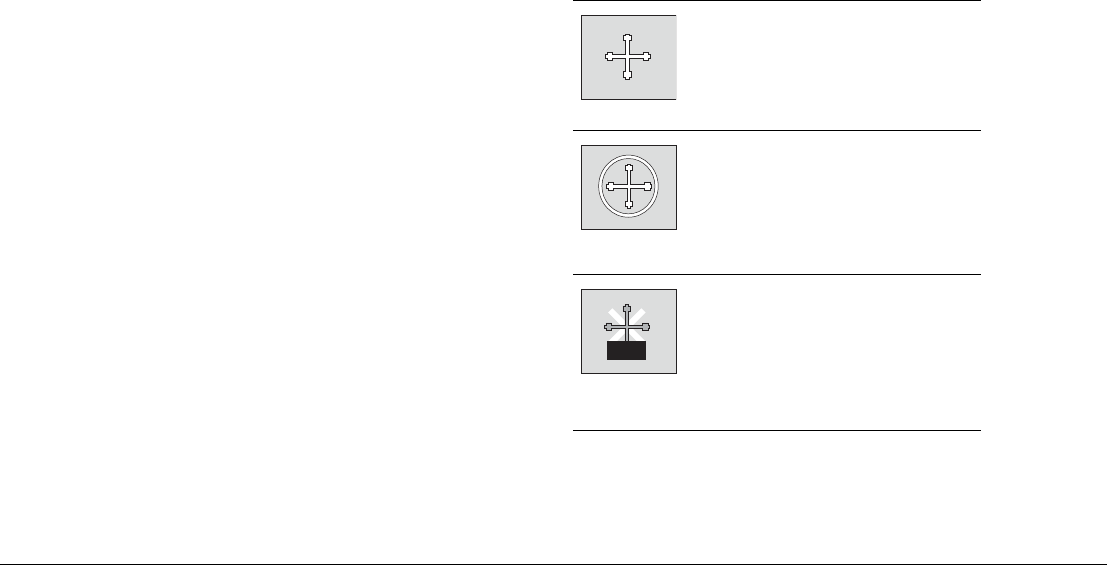
1.1 Hardware overview
The diagram below shows a G-Series system with one GPM400 and two monitors (second monitor is a repeater).
D9985-1
9
WXYZ
8
TUV
7
PQRS
4
GHI
5
JKL
6
MNO
ACTIVE
WPTS
MOB
DATA
MENU
PAGE
.0
2
ABC
3
DEF
1
CANCEL
STANDBY
DODGE PILOT OK
RANGE
OUT
IN
ENTER
ENTERCANCEL
MENU
ENTERCANCEL
MENU
ENTERCANCEL
MENU
ENTERCANCEL
MENU
Navstation 1
Keyboard
Monitor 1 Monitor 2
(repeater)
SeaTalk
Alarm
sounder
SeaTalkHS
SeaTalkHS
SeaTalk NG
SeaTalkHS
network devices
SeaTalk NG
DVI/VGA
DVI/VGA
NMEA 0183
GPS
SeaTalkHS switch
SeaTalkNG Instruments/pilot
and/or
SeaTalk Instruments/pilot
GPM 400
DSM 300
Digital radar
AV server
Video/audio sources
15 Chapter 1: System Overview
1.2 Display and keyboard
You access the features and functions of a G-Series system through Nav Stations, which comprise monitors and keyboards. This section
gives you an overview of the controls in a Nav Station. For detailed information about how to operate the system, see Chapter 2:Operating
Principles on page 21.
Keyboard controls
The diagram above shows the layout of controls on a G-Series key-
board. If you have more than one monitor in your Nav Station, you
can switch between monitors from the keyboard. You can also use
the keyboard at different Nav Stations on your vessel.
Power button
Controls system power. For further information, see Controlling
system power on page 32.
Rotary controller
Choose items in menus or lists. Turning the controller clockwise or
counterclockwise moves the highlight down or up through the list of
available options.
You also use the rotary controller to select letters when you enter
text and to set values on sliders.
Trackpad
Moves the on-screen cursor. The trackpad provides movement in
eight directions.
9
WXYZ
8
TUV
7
PQRS
4
GHI
5
JKL
6
MNO
ACTIVE
WPTS
MOB
DATA
AUTOPILOT CONTROL KEYS
MENU
TRACKPAD
ROTARY
CONTROLLER
OSD CONTROLS
PAGE
.
0
2
ABC
3
DEF
1
CANCEL
STANDBY
SOFTKEYS
DODGE PILOT OK
RANGE
OUT
IN
ENTER
D10547-1
OS
D
CO
NTR
O
L
S
ENTER
SO
FTK
E
Y
S
A
U
T
O
PI
L
O
T
CO
NTR
O
L K
E
Y
S
S
T
ANDB
T
T
Y
DO
D
GE
PIL
O
T

G-Series Reference Manual 16
You also use the trackpad to navigate system menus: move up or
down through option lists and press trackpad-right to select the
next menu level if there is one.
Softkeys
Asoftkey is a button whose function changes according to your
task. The current function of each softkey is indicated in the tool-
bar, the strip of softkey labels along the bottom of the monitor.
Softkeys are color-coded with softkey labels.
OK
Confirm the selection of a highlighted list, menu or screen object.
Cancel
Press the cancel button to undo an action or keypress. For exam-
ple, if you make an incorrect menu or toolbar selection, press
cancel to go back to the previous screen.
Range
Change the scale of a chart, radar or fishfinder view. Range in to
decrease the scale (closer view), range out to increase the scale
(more distant view).
Page
Switch to a different page view. Press-and-hold to configure page
sets.
WPTS/MOB
Place waypoints (WPTS) or a Man Overboard Marker (MOB) and
access waypoint functions.
Menu
Open menus for changing system- or application-wide settings.
Active
In multi-window views, cycle through windows to make each active
in turn. Active windows are marked with a red border. Press-and-
hold to make the current active window full-screen.
Data
Open the data toolbar for the current application and access
databar preferences.
Autopilot control keys
If you have a Raymarine autopilot connected to the G-Series sys-
tem, you can control some of its features from the G-Series
keyboard.
•Standby puts autopilot on standby.
•Dodge to be implemented in future Raymarine product
releases.
•Pilot displays the autopilot control screen.
Alphanumeric keys
Edit waypoint data.
Menu symbol
Open the on-screen menu when using a Raymarine monitor.
Up/Down
Select a different Nav Station if more than one is assigned to the
keyboard.
Left/Right
Select a different monitor if more than one is assigned to the
keyboard.
Enter
Confirm a selection in the on-screen display settings menu.

17 Chapter 1: System Overview
Display controls
If you have a Raymarine monitor you can customize display set-
tings, including choosing between day or night-time color palettes,
using the G-Series setup menus. For information about how to do
that, see Introducing Nav Stations on page 22.
There are also controls on the front of Raymarine displays, summa-
rized below:
Some of these controls are replicated on the keyboard and you can
use them to adjust Raymarine monitors.
1.3 Installing and commissioning
This book assumes that a G-Series system has already been cor-
rectly installed and commissioned on your vessel. If you are about
to install or commission a G-Series system, see the following docu-
ments for more information:
• Raymarine G-Series Installation Manual
• Raymarine G-Series Commissioning Guide
1.4 System applications
The features and functions of the G-Series system are grouped
together in applications. Applications included on the system are
summarized on the following pages.
VGA 2/
Scroll DOWN
DVI 1/
Scroll LEFT
DVI 2/
Scroll RIGHT
Composite
Video 1/
PIP
Composite
Video 2/
Brightness
Composite
Video 3/
Night mode
D10548-1
S-Video/
Enter
POWER
VGA 1/
Menu
VGA 3/
Scroll UP
G-Series Reference Manual 18
Chart
3D chart
Fishfinder
Radar
Data
Video
D9519-1
• Locate where you are
• Interpret your surroundings.
• Monitor where you are going.
• Record where you have been.
• Navigate to a specified position (waypoint).
• Build and navigate routes.
• View details of nearby features & services.
• View details of boats equipped with AIS.
• Distinguish between fixed & moving objects.
• Measure distances and bearings.
D9520-1
• Display a 3D view of land, sea & features.
• Locate where you are.
• Interpret your surroundings.
• Monitor where you are going.
• Go to an existing waypoint.
• Navigate a route.
• Synchronize with the 2D chart.
• Identify fishing spots.
D9521-2
• See where the fish are.
• Identify underwater objects.
• View seabed structure.
• View sea depth and temperature data.
• Mark points of interest, like fishing spots or
wrecks.
D9525_1
• Detect landmasses & navigation markers.
• Detect and measure the range and distance
of other vessels.
• Acquire targets and track them for collision
avoidance.
•
Navigate to a specified position
(waypoint).
• View details of boats equipped with AIS.
D9527-1
• View data generated by the system or by
instruments available on NMEA 0183,
NMEA 2000, J1939, SeaTalk or SeaTalk2.
D9528-1
• View video images from on-board CCTV
cameras, DVD or video player.
19 Chapter 1: System Overview
Course Deviation Indicator
Engine Monitor
Sirius Weather
Navtex
Sirius Audio
You can receive and manage radio broadcasts on the G-Series
system using Sirius Audio (Sirius SR100 data receiver required).
Autopilot
If you have a Raymarine autopilot installed, you can make use of
the pilot control features of the G-Series system. You can engage
the autopilot from the G-Series keyboard instead of the pilot control
head.
D9522-1
• View real-time display of your vessel on a
'rolling road' in 3D perspective.
• Give details of any correction required to
steer your vessel along a given course.
• View data about the distance and time to
go until you reach a specified point.
D9530-1
• View engine data e.g. engine temperature,
oil pressure, fuel level etc from up to three
engines on a compatible engine system.
D9523_1
• Only available for the US.
• Superimpose historical and forecasted
weather graphics on a world map.
• Determine conditions in your vicinity or at a
particular location.
• View weather reports.
D9531_1
• Automatic broadcast of localised Maritime
Safety Information (MSI)
• Receive navigational and meteorological
warnings, and search and rescue
information.

G-Series Reference Manual 20

2
Chapter 2: Operating Principles
The first section of this chapter introduces Nav Stations: the networked keyboards and monitors you use to
operate the G-Series.
The second section describes how you control the applications using the various buttons,softkeys,menus
and toolbars.
The operating principles described in this section apply to all applications. Understanding them will help you
use the system efficiently.
Chapter contents
• 2.1 Introducing Nav Stations on page 22
• 2.2 Using the applications on page 22
• 2.3 Displaying applications on page 25
• 2.4 On-screen information on page 28
• 2.5 Simulator mode on page 29
• 2.6 Emergencies and warnings on page 29
G-Series Reference Manual 22
2.1 Introducing Nav Stations
A Nav Station comprises one or more monitors and associated key-
boards grouped at a particular location. For example, you might
have one Nav Station on the fly bridge and one at the cockpit. The
Nav Station is where you access the functions and features of a G-
Series system.
Data is shared over the network and repeater monitors let you see,
for example, the same information on the bridge as is available in
the cockpit. You can control the system from either location.
For information about managing and configuring Nav Stations, see
Nav Station Setup on page 31.
Monitors
For each monitor, you can have a repeat monitor. This is driven by
the same GPM400 as the first monitor, but would be placed at a dif-
ferent Nav Station to make information available at two locations.
Keyboard
A keyboard can be assigned to one or all monitors in your system,
but can only control one monitor at a time. You can select which
monitor you want to control from the keyboard. When a keyboard is
associated with a monitor, this provides full control of the system.
For more information about using keyboards with monitors and Nav
Stations, see Keyboard settings on page 33.
2.2 Using the applications
An application is what you open to use the features of the G-Series
system. For a list of applications, see System applications on
page 17.
All the applications included on the G-Series operate on the same
principles. You set them up and use them using a combination of
menus and toolbars.
This section explains the general operating principles behind these
various elements. Detailed application-specific information is given
in the subsequent chapters of this book.
The cursor
In relevant applications, move the cursor over objects or areas on
screen to highlight them. Once highlighted, the system recognizes
that subsequent actions apply to the highlighted object.
Use the trackpad to move the cursor.
Standard cursor.
If the cursor is not moved for
a while, a white circle is put
around it to make it easier to
locate.
When you highlight an
object, the cursor changes
color.
D7366_3
D7368_2
D7369-2
WPT
23 Chapter 2: Operating Principles
Toolbars and softkeys
A toolbar is a set of softkey labels displayed along the bottom of a
display. Each label is color-keyed to match the corresponding soft-
key on the keyboard.
Pressing a softkey can cause a new toolbar to appear, call up an
options window or menu list, or trigger an action such as setting
your vessel on a track to a selected waypoint. Some softkeys have
sliders or pop-ups associated with them, where you make setting
adjustments using the rotary controller or trackpad.
It is useful to think of toolbars arranged in tiers. To access some
functions, you need to go to a second or third tier. If you acciden-
tally press the wrong softkey, you can go back up a tier by pressing
the CANCEL button.
If there are tiers below a softkey, the softkey label ends with an
ellipsis (…). For example, pressing “GOTO…” on the navigation
toolbar opens the GOTO toolbar, giving you access to further
options.
Note: When instructions in this book refer to softkey labels, the
ellipsis is not included.
Setup menus
Menus are where you make system- or application-wide changes.
Pressing the MENU button opens the Setup menu. From there you
can choose application setup menus or system setup menus.
The application setup menus are context-sensitive: if you are in the
chart application, for example, the chart setup menu is available.
For more information about the setup menus for each application,
see the appropriate chapter of this book. For all other settings, see
Chapter 18:System Setup and Customizing on page 187.
To change a menu setting
1. Select the appropriate menu:
D9557-1
Radar Setup ...
GPS Status...
Compass Setup...
AIS Layer Status...
System Setup...
Alarm Setup...
Display Setup...
Databar Set...
Select Page Setup...
System Diagnostics...
Remove CF Card
Setup
Menus for the
active application
External equipment/
instruments
System-wide menus
MENU
D9597-1
Setup Cartography Setup Menu
Chart Display Detailed
Chart Grid On
Chart Text On
Chart Boundaries ON
Spot Soundings ON
Chart Setup...
Cartography Setup...
GPS Status...
Compass Setup...
1. Highlight item, using:
2. Select item, using:
Trackpad
(up/down)
Trackpad
(right)
Rotary
control
or
1. Highlight item, using:
2. Select item, using:
Trackpad
(up/down)
Trackpad
(right)
Rotary
control
or
G-Series Reference Manual 24
2. Change the setting:
3. Press OK to accept your changes, or CANCEL to go back to
the previous screen.
Dialog boxes
Dialog boxes are where you edit or enter data into the system.
They appear automatically at appropriate points. For example,
when you edit a list of waypoints, a dialog box appears for you to
enter or change waypoint names.
To enter data into a dialog box
1. Select the appropriate field.
2. Enter the data. Press OK to save the changes.
3. Repeat Steps 1 and 2 if necessary.
You can enter character text in upper- or lower-case but the system
is not case sensitive: it considers ‘WAYPOINT 1’ to be the same as
‘Waypoint 1’.
To use special or accented characters, turn on the Extended Char-
acter Set in the System Setup Menu (see page 192).
D9559-1
Cartography Setup Menu
Highlight or change value
to new setting, using:
Trackpad
(up/down)
Rotary
control
or
Chart Display Detailed
Chart Grid On
Chart Text On
Chart Boundary ON
Spot Soundings ON
Safety Contour 66ft
Depth Contour ALL
Nav. Marks ON
OFF
7ft
10ft
16ft
20ft
33ft
66ft
D9560-1
Highlight field to be edited
e.g. waypoint
e.g.
EDIT NAME
Name
Symbol
Group My Waypoints
Comment
Waypoint 1
D9561-1
e.g.
Name
Symbol
Group My Waypoints
Comment
Waypoint 1
OK
To change character or selection, use:
,
To move to next character for editing, use:
or
25 Chapter 2: Operating Principles
2.3 Displaying applications
Each G-Series application is displayed in a window. The system
can display up to four windows at once, on a single page.
You can configure pages to contain the window or windows that
best suit your requirements. You can also create page sets, each
set comprising up to five customized pages, so that you can switch
between different application views easily.
Choosing page sets
Page set configurations apply to the monitor on which you are
working. You can display different pages on other monitors in your
Nav Station.
To select a page set
1. Press and hold PAGE.
2. Select your preferred page set.
3. Press OK.
or
1. Press MENU to open the system Setup menu.
2. Choose Select Page Set.
Page set
Page
(consists of 1, 2, 3 or 4 windows
in various configurations)
Window
D9532-1
CDI 2D Chart
Weather 3D Chart
Video Engine monitor
Fishfinder Data Radar
DD9535-1
PAGE OK
Highlight appropriate
pre-configured page set
Press & hold
G-Series Reference Manual 26
None of the preconfigured sets includes a page for the engine
monitor,weather or video applications. To configure a set that
does, or to create a custom set for any combination of applications,
see the Setup and Customizing chapter of this book.
Selecting an application page
Once you have selected the appropriate page set, you can choose
the view you want to use.
To view an application page
1. Press PAGE.
2. Either select the application page you want from the toolbar or
toggle between the applications configured in the page set by
pressing PAGE.
3. Press OK or CANCEL.
Selecting application windows
When the selected page has more than one window, the window
that is currently active has a red border. The toolbar applies to the
active window.
To change the active window
1. Press ACTIVE to toggle active status between windows (the
red border moves to highlight the active window).
To toggle between multiple- and single-window views
1. In a multiple-window view, press and hold the ACTIVE button
to display the active window at full-screen.
2. Press ACTIVE once more to return to multiple-window view.
D9537-2
Soft keys associated with active window
Active window highlighted

27 Chapter 2: Operating Principles
Panning and zooming
In the appropriate application windows, you can pan and zoom the
view to display a different geographic area (pan) or change the
scale at which an area is displayed (zoom).
Panning
In the chart, 3D chart and weather applications, you move the cur-
sor using the trackpad. When the cursor reaches an edge of the
screen, the view automatically pans to display the appropriate area.
Zooming
In chart, 3D chart, fishfinder, weather or radar windows, you can
use the Range In / Out rocker switch to change the scale of the
view. When you zoom in, you see a smaller area of the chart in
more detail (large scale). When you zoom out, you see a greater
area of the chart in less detail (small scale).
The level of cartographic detail available at different scales varies.
Some charts provide detail at smaller scales than others.
If you select a chart scale that does not provide cartographic detail
for your chosen area, the chart will use the most detailed level
available for the surrounding area and stretch it to fit the selected
scale. This means that you will never have blank or hatched areas
on your screen. However there may be some mis-alignment of
objects which cross the chart boundary in this area.
G-Series Reference Manual 28
2.4 On-screen information
Information is displayed on screen in a variety of ways:
* For details of how to adjust and edit the data bar, see page 188
Note: To change the size of the text on screen, see page 191.
MARPA ALARM
Target lost (on screen)
ACKNOWLEDGE
D9533-1
Status bar
• Gives information specific to
each application.
• Cannot be edited or moved.
Data bar
• Gives information associated with
your boat or the environment.
• Customisable content*.
• Vertical or horizontal format*.
• Display or hide*.
• Normal or large size*.
Data base lists
• Contain information you have added to the
display's memory e.g. waypoints.
• Highlight an entry using trackpad or rotary
control to display related information.
• Editable using soft keys.
Pop-up messages
• Alert you to a situation e.g. alarm, function
not available.
• Not editable.
• May require a response e.g. press
ACKNOWLEDGE to silence alarms.
Dialog boxes
Enable data to be edited or entered into a
store/list e.g. editing a waypoint.
Menus (see next page)
Used to configure system to your
particular needs.
Status icons
Confirm status of DSM,
GPS, AIS and scanner.

29 Chapter 2: Operating Principles
2.5 Simulator mode
The G-Series Display includes a simulator mode which allows you
to practice operating the display without data from a GPS antenna,
radar scanner, fishfinder (DSM) unit or an AIS receiver.
Once enabled, you can use the simulator:
•Before installation: connect the system to a 12V DC power
supply, fused at 1 amp by attaching the red core from the power
lead to positive (+) and the black core to negative (-).
•After installation while in a marina or at anchor.
Settings made in simulator mode are not transmitted to other
equipment.
Incoming AIS safety messages are not displayed in
simulator mode.
To switch simulator mode on
1. Press the MENU button to open the Setup menu.
2. Select Simulator.
3. Select ON.
4. Press OK.
2.6 Emergencies and warnings
You can use your G-Series system to mark the position of a man
overboard, or to sound warning alarms in particular situations.
Man overboard
If you lose a person or object overboard and need to return to the
spot, activate the Man Overboard (MOB) function immediately.
The MOB function is available at all times, whatever application is
running on the G-Series system.
To activate the Man Overboard function
1. Press and hold the WPTS/MOB key for three seconds.
The G-Series can also receive a MOB message from other equip-
ment on the SeaTalk system.
Placing a MOB marker initiates a set of actions on the G-Series
system:
•Waypoint placed at your current position.
•Alarm sounds in morse, repeated every 30 seconds.
•Positional information including bearing, range and position
are displayed in the databar. These are calculated according to
the MOB configuration specified in the System Setup Menu. As-
suming that your boat and the MOB are subject to the same tide
and wind effects, dead-reckoning normally gives a more accu-
rate course.
•Radar range set to 1/8 nm if in transmit mode.
•Navigation functions are suspended and no new GOTO or
route functions are selectable.
•Motion mode set to autorange if radar/chart synchronization
is set to OFF (see page 64). The chart application changes the
motion mode to Autorange to display the largest possible scale
of chart that will include both the MOB waypoint and your
vessel.
• MOB message transmitted to other Raymarine equipment.
•Current position to MOB position is represented on screen
by a dotted line.
Note: To obtain a MOB position, you need either position or
heading and speed data from a GPS (or equivalent) device.
To pause a MOB alarm
1. Press any key on any instrument on the SeaTalk system.
After approximately 10 seconds the alarm will sound again if the
MOB function is still active.
Pausing an alarm does not deactivate or clear the MOB state.
Cancelling a MOB alarm
Clearing a man overboard alarm has the following effects:
• The motion mode in the chart and radar applications is reset.

G-Series Reference Manual 30
• The databar mode is reset.
• GOTO and route functions return.
Note: If you have a MOB keypad fitted, you can also press and
hold the MOB key.
To cancel a MOB alarm
1. Press and hold the WPTS/MOB key for four seconds.
Warning alarms
You can configure the G-Series system to sound an alarm when it
detects a hazard or a particular situation. When the alarm sounds,
a message box is displayed to explain the reason for the alarm.
For a full list of alarms available, see Alarm Setup Menu on page
194.
To set up alarms
1. Open the Alarms setup menu.
2. Make your desired settings using the appropriate menu options.
3. Press OK to save your settings.
Cancelling alarms
There are two kinds of alarm: system and external.
System alarms are triggered by G-Series applications, like the
chart or radar. When you cancel a system alarm, the G-Series can-
cels the alarm and makes appropriate changes to the application
that triggered it. For example, if the chart application sounds an
arrival alarm, navigation to the next waypoint in the route starts
when you cancel the alarm.
External alarms are triggered by equipment that is connected to
the G-Series system, but which is not part of the G-Series system.
When you cancel an external alarm, the alarm stops but no further
action is taken.
You cancel both types of alarm in the same way.
To cancel an alarm
1. Press the ACKNOWLEDGE softkey.
• If an anchor alarm is silenced but the alarm condition persists,
the alarm is repeated every 30 seconds.

3
Chapter 3: Nav Station Setup
This chapter describes initial power-on and system setup procedures.
Chapter contents
• 3.1 Controlling system power on page 32
• 3.2 Monitor settings on page 32
• 3.3 Keyboard settings on page 33
• 3.4 Setting language, date and time, and units of measurement on page 33
• 3.5 Local settings on page 33
G-Series Reference Manual 32
3.1 Controlling system power
The power button on the keyboard controls power to G-Series keyboards and displays. It also controls power to the radar scanners.
To open the power control screen
1. With the system powered on, press the power button once.
Note: The power button does not control power to the GPM400
unit.
The power control screen
Once power is applied to the system, pressing the power button
opens the power control screen which gives you access to:
• Power and transmit settings for two radar systems.
• Brightness and power settings for the monitors.
• Monitor palette selection.
3.2 Monitor settings
If you are using a Raymarine monitor, the power control screen
allows you to set the monitor brightness level and color palette. You
can also control monitor power states.
To adjust monitor brightness
1. Open the power control screen.
2. Use the rotary controller to set the brightness level you require.
3. To change the brightness of a monitor in a different Nav Station,
press the rotary controller once and select the appropriate Nav
Station from the list.
4. To accept your changes, press OK.
PWR
Palette options
OSD controls
Monitor power
RADAR 1
TX STBY
RADAR 1
ON OFF
RADAR 2
TX STBY
RADAR 2
ON OFF
MONITOR
CONTROLS
D10549-1

33 Chapter 3: Nav Station Setup
To select a different color palette
1. On the power control toolbar, press MONITOR CONTROLS.
2. Toggle to the palette you want to use on the PALETTE softkey.
3. Press OK.
3.3 Keyboard settings
When a system is commissioned, settings are made which associ-
ate keyboards with Nav Stations and displays. This allows you to
use one keyboard to control different Nav Stations or monitors (but
only one at a time).
To use the keyboard at a different monitor
1. Press the left/right arrows on the keyboard to select the name
of the display you want to use.
To use the keyboard at a different Nav Station
1. Press the up/down arrows on the keyboard to select the name
of the Nav Station at which you want to use keyboard.
3.4 Setting language, date and time,
and units of measurement
All these settings are configured from the system Setup menu.
To configure language, units, date and time format
1. Open the system Setup Menu.
2. Select the settings you want to configure.
3. Make the appropriate changes.
4. Press OK.
Note: For information about to change menu settings, see Setup
menus on page 23.
3.5 Local settings
The majority of functions, settings, and changes that you make on
a Nav Station are detected by all the Nav Stations in the system.
There are, however, some local settings that affect only the monitor
on which you are working (and its repeater if there is one).
These local settings are:
• Page set: selecting a set, name and applications configuration.
• The active window.
• The displayed panel in the digital data or engine monitoring
application.
• Radar and Fishfinder presentation settings.
• Radar VRM, EBL and wakes.
• Chart presentation settings when chart view is set to local.
• Show/hide waypoints, routes and tracks.
• Display Setup Menus.
• Databar on/off and configuration.
• Chart ruler settings.

G-Series Reference Manual 34

4
Chapter 4: Using Waypoints
This chapter introduces waypoints and explains how to use them for navigation with the G-Series system.
Chapter contents
• 4.1 Introducing waypoints on page 36
• 4.2 The waypoint toolbar on page 37
• 4.3 Waypoint list on page 38
• 4.4 Placing waypoints on page 38
• 4.5 Navigating to waypoints on page 39
• 4.6 Waypoint information on page 39
• 4.7 Editing waypoints on page 39
• 4.8 Sorting the waypoint list on page 41
• 4.9 Waypoint groups on page 41
G-Series Reference Manual 36
4.1 Introducing waypoints
Waypoints are used to mark points to navigate to, for marking loca-
tions for fishing and diving, and as building-blocks in routes.
Waypoints can be created in any application and displayed on the
radar, chart and fishfinder windows. They can be viewed on all the
displays in a G-Series system.
Weather window
A waypoint can be placed when a Weather application window
is active but it will not be seen in the weather window.
Radar and 2D chart windows
A waypoint is represented on a radar or chart window when it is
inactive or active (i.e. you are navigating to it). The waypoint
symbol can be changed if required.
Wpt 2
Wpt 1
Active waypoint (boxed)
Active waypoint
Alternative waypoint symbols
Fishfinder window
When a waypoint is created it
is represented on fishfinder
windows, by a vertical line
labelled WPT. This symbology
cannot be changed.
WPT
WPT
WPT
WPT
3D chart and CDI windows
A waypoint is represented only when it is active i.e. you are
navigating to it.
D9496_1
37 Chapter 4: Using Waypoints
4.2 The waypoint toolbar
Pressing the WPTS/MOB button opens the toolbars shown below:
WAYPOINT AT
CURSOR
WAYPOINT AT
VESSEL
WAYPOINT AT
LAT/LON
GOTO WAYPOINT
OPTIONS
REVIEW AND EDIT
WAYPOINTS
Set up default symbol/group
Edit default
Sort list
Set default symbol and group
Waypoint groups
View and edit details
Erase waypoints
Move between groups
Rename group
Make new group
Erase groups
Edit group name
D10550-1
G-Series Reference Manual 38
4.3 Waypoint list
The details of all waypoints, irrespective of the application they
were created in, are stored in a dedicated waypoint list which holds
up to 3000 waypoints. All waypoints are placed in the MY WAY-
POINTS group by default. You can create new groups and change
the default group.
You can store waypoints on a CompactFlash card or transfer them
to other NMEA-compatible instruments. If the G-Series system
receives an active waypoint over SeaTalk or NMEA, it is displayed
but cannot be edited.
Waypoint lists can be password protected.
4.4 Placing waypoints
You can place a waypoint at:
• The cursor position
• Your vessel’s position
• A point specified by latitude and longitude or Loran TD
coordinates.
WAYPOINT AT
CURSOR
WAYPOINT AT
VESSEL
WAYPOINT AT
LAT/LON
GOTO WAYPOINT
OPTIONS
REVIEW AND EDIT
WAYPOINTS
Advance waypoint
Stop goto
Restart XTE
Place waypoint
Goto waypoint
D10551-1

39 Chapter 4: Using Waypoints
To place a waypoint at the cursor
1. Press the WPTS/MOB button.
2. Move the cursor to the waypoint position.
3. Press the WAYPOINT AT CURSOR softkey.
4. Press OK.
To place a waypoint at your vessel’s position
1. Press the WPTS/MOB button.
2. Either Press the WAYPOINT AT VESSEL softkey or press the
WPTS/MOB button a second time.
3. Press OK.
Note: If the system cannot determine your position, a warning is
displayed and the waypoint is not placed.
To place a waypoint by latitude and longitude
1. Press the WPTS/MOB button.
2. Press the WAYPOINT AT LAT/LON softkey.
3. Set the position for the new waypoint.
4. Press OK.
4.5 Navigating to waypoints
This section explains how to start and stop navigating to a way-
point. When you navigate to a waypoint, the data is sent over the
network and can be used by an attached autopilot. A waypoint
being navigated to is known as an active waypoint.
For detailed information on navigating with waypoints, see page 43.
To navigate to a waypoint
1. Highlight the waypoint.
2. Press the GOTO WAYPOINT softkey.
or
1. Press either the WPTS/MOB button or GOTO softkey.
2. Press the GOTO WAYPOINT OPTIONS softkey.
3. Select the appropriate waypoint from the list.
4. Press GOTO WAYPOINT.
To stop navigating to a waypoint
1. Highlight the waypoint.
2. Press the STOP GOTO softkey.
or
1. Press the WPTS/MOB button.
2. Press the GOTO WAYPOINT OPTIONS softkey.
3. Press the STOP GOTO softkey.
4.6 Waypoint information
Waypoints have information associated with them. You can view
the details of any waypoint by either highlighting it with the cursor
(in radar and chart windows) or selecting it from the waypoint list.
With the waypoint details open, you can edit the data and change
its management options.
You can also display navigation details for the active waypoint in
the databar (see page 188).
To view waypoint information
1. Highlight a waypoint with the cursor.
2. Press the EDIT WAYPOINT softkey.
or
1. Press the WPTS/MOB button.
2. Press the REVIEW AND EDIT WAYPOINTS softkey.
Note: Use the second method to view details for an active
waypoint.
4.7 Editing waypoints
The G-Series system allows you to edit and modify the followings
aspects of a waypoint’s details.
• Change the waypoint name.
• Change the waypoint symbol.
G-Series Reference Manual 40
• Change the waypoint group.
• Add a comment.
• Move a waypoint.
• Erase a waypoint.
• Change the default symbol and group of newly placed
waypoints.
Changing the waypoint name, symbol or group
When you create a waypoint, the system automatically assigns it a
name, symbol and group. You can change these details and add a
comment if required. This is particularly useful if you are managing
a large quantity of waypoints.
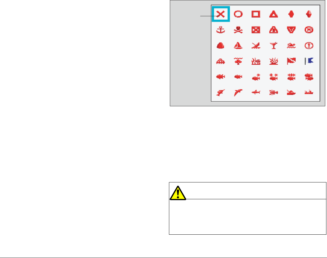
The default waypoint symbol is X.
You can select different waypoint symbols to mark different types of
position (fish or dive locations, for example). When a waypoint is
active (being navigated to), the system highlights it by placing a red
box around it.
Alternative waypoint symbols available are shown below.
To edit waypoint details
1. Highlight the waypoint or select it in the waypoint list.
2. Press the VIEW AND EDIT DETAILS softkey.
3. Select the field you want to change and press the appropriate
softkey.
4. Make changes as required.
5. Press OK to save your changes.
Moving waypoints
Caution
Moving waypoints
If you move a waypoint that is used in a route, the new
position will be updated within that route. Ensure that
this does not present a navigation hazard.
D9440_1
Default symbol

41 Chapter 4: Using Waypoints
You can move any waypoint except the active one. There are two
methods of moving a waypoint: by entering a new set of coordi-
nates for it (under the VIEW AND EDIT DETAILS softkey), or by
selecting and dragging it to a new position.
To drag a waypoint to a new position
1. Highlight the waypoint.
2. Press the MOVE WAYPOINT softkey.
3. Use the trackpad to drag the waypoint to its new location.
4. Press the PLACE WAYPOINT softkey.
Deleting waypoints
You can erase any waypoint except an active waypoint or one that
is part of a saved route.
Note: If a route is hidden, its waypoints can still be displayed. If
you attempt to erase a waypoint from a hidden route, a
warning message will be displayed.
To erase an individual waypoint
1. Highlight the waypoint.
2. Press the ERASE WAYPOINT softkey.
3. Confirm the deletion.
or
1. Open the waypoint list.
2. Press the REVIEW AND EDIT WAYPOINTS softkey.
3. Select the waypoint from the list.
4. Press the ERASE WAYPOINT softkey.
5. Confirm the deletion.
To erase all waypoints
1. Press the DATA button.
2. Press the ARCHIVE AND TRANSFER softkey.
3. Press the ERASE FROM SYSTEM softkey.
4. Highlight WPT on the SELECT LIST softkey.
5. Select ERASE ALL WAYPOINTS.
6. Confirm the deletion.
4.8 Sorting the waypoint list
You can sort the waypoint list to make it easier to manage. This fea-
ture is particularly useful when you have a large number of
waypoints.
You can sort the waypoint list by:
• Name (default)
• Range (closest first)
• Symbol
• Group name
• Date
• Comment
• Depth
To sort the waypoint list
1. Press the SORT LIST softkey.
2. Press the SELECT SORT OPTION softkey.
3. Choose a sort method from the list.
4. Press OK.
4.9 Waypoint groups
All new waypoints are automatically placed in a group called “My
Waypoints”. To make waypoints easier to manage, you can orga-
nize them into different groups. When fishing, for example, you can
choose to see only the waypoints in a fishing group that includes all
your good fishing sites.
A waypoint can belong to one group only.
Waypoint groups are managed from the waypoint group list.

G-Series Reference Manual 42
To open the waypoint group list
1. Press the WPTS/MOB button.
2. Press the REVIEW AND EDIT WAYPOINTS softkey.
3. Press the WAYPOINT GROUPS softkey.
You can now:
• Make a new group
• Move waypoints between groups
• Rename groups
• Delete groups
To make a new waypoint group
1. Open the waypoint group list.
2. Press the MAKE NEW GROUP softkey.
3. If you want to give the group a name other than the default,
press EDIT GROUP NAME and set the name.
4. Press OK.
To move waypoints between groups
1. Open the waypoint group list.
2. Press the MOVE BETWEEN GROUPS softkey.
3. Press SELECT GROUP A and select the group to move the
waypoint from.
4. Press SELECT GROUP B and select the group to move the
waypoint to.
5. Highlight the waypoint you want to move.
6. Press MOVE WAYPOINT FROM A TO B.
7. Press OK when done.
To rename a group
1. Open the waypoint group list.
2. Highlight the group you want to rename.
3. Press the RENAME GROUP softkey.
4. Press the EDIT GROUP NAME softkey.
5. Enter the new name.
6. Press OK.
Deleting groups
When you erase a group, the group name and all the associated
waypoints are removed from the system. If a group contains one or
more waypoints that you want to keep, move those waypoints out
of the group before you delete it.
You can erase any waypoint group, with the following exceptions:
• You cannot erase the “My Waypoints” group.
• You cannot erase a group containing an active waypoint.
• You cannot erase a group containing waypoints that are part of
a stored route.
To delete a group
1. Open the waypoint group list.
2. Select the group you want to delete.
3. Press the ERASE GROUP softkey.
4. Confirm the deletion.

5
Chapter 5: The Chart Application
The chart application provides navigation, hazard awareness and planning features. Use the chart applica-
tion to establish your position; navigate using waypoints and routes; record your progress; measure distance
and bearing; overlay chart and radar data; view AIS data, and view aerial photography.
For information about autopilot integration, see page 85.
Chapter contents
• 5.1 Warnings and cautions on page 44
• 5.2 Supplied cartography on page 44
• 5.3 Chart Overview on page 45
• 5.4 Chart setup on page 46
Navigation
• 5.5 Quick waypoints on page 50
• 5.6 Building a route on page 52
• 5.7 Tracking your progress on page 60
• 5.8 Heading and course information on page 62
• 5.9 Presentation options on page 63
• 5.10 Showing and hiding waypoints on page 64
Hazard awareness
• 5.11 Chart layers on page 64
• 5.12 Chart mode and orientation on page 66
• 5.13 Chart view on page 68
• 5.14 Chart detail on page 68
Planning
• 5.15 Journey planning on page 69
• 5.16 Measuring distance, range and bearing on page 73
G-Series Reference Manual 44
5.1 Warnings and cautions
Always check that your route is safe. Use the Range key to zoom in
to check for hazards that may not be visible on a larger scale view.
Until you are familiar with interpreting the chart display, take every
opportunity to compare what’s on the chart display with your actual
surroundings. Practice harbour and coastal navigation during day-
light hours and in clear weather conditions.
You can also use simulator mode to help you gain experience with
the unit.
Before you use the chart application, make sure you have read and
understood Chapter 4:Using Waypoints on page 35.
CAUTION:
The Chart application is not a substitute for good
navigational practice, nor does it remove the need for
official government paper charts. Do not use the G-Series
Chart application before you have read this chapter.
Requirements
1. For full functionality, the chart application needs to be receiving
position and heading data from your vessel’s Global Positioning
System (GPS).
2. For your GPS and chart to correlate accurately with your paper
charts, they all need to use the same datum. The default datum
for the G-Series system is WGS84. If this is not suitable, you
can change the setting in the Chart Setup menu (see page 46).
When you adjust the datum of the G-Series system, a Rayma-
rine GPS will automatically correlate. If you have a third-party
GPS, you need to adjust it separately. Refer to the instructions
that came with your GPS for more information.
3. For the Automatic Identification System (AIS) to function you
must have a suitable AIS receiver connected.
4. For full autopilot functionality, you must have a compatible auto-
pilot attached to your G-Series system.
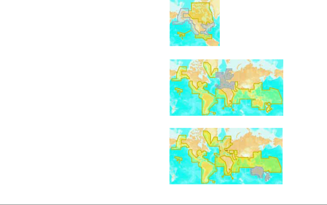
5.2 Supplied cartography
The G-Series system comes preloaded with Navionics cartography.
Depending on your region, different levels of cartography (Platinum
or Gold) are available in different areas.
You can also use Navionics chart cards. When chart cards are
present, the system selects the latest cartography to display.
US
Europe
Rest of world
45 Chapter 5: The Chart Application
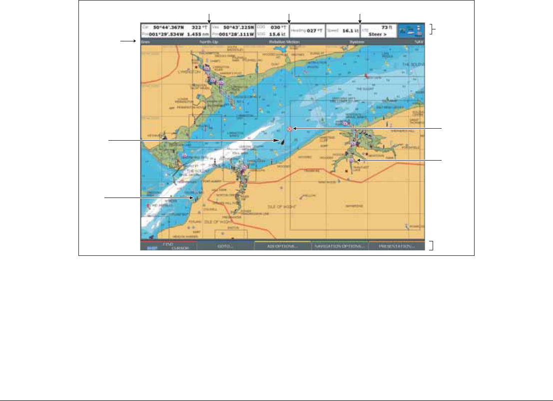
5.3 Chart Overview
The illustration below shows the components of a typical chart view.
Your position
Your position is displayed in the data bar under VES POS. If head-
ing or COG data is available, your position is represented on
screen by a boat symbol; if heading or COG data is not available,
your position is represented by a solid circle.
The display tells you which orientation and motion mode you are in.
For more details, see page 66.
If your position is outside the area of chart currently shown in the
chart window, the vessel symbol will not be visible. You can tell the
system to locate your vessel and centre the chart display about it.
To locate your vessel
1. Toggle to SHIP using the FIND softkey.
This puts your vessel on screen, as long as the system has a fix for
your location.
Chart range
Chart orientation Motion mode
Status
bar
Current
position
Carto-
graphic
object
Active
waypoint
Softkeys
D6605_3
Chart view
Port
Services

G-Series Reference Manual 46
5.4 Chart setup
Navionics cartography comes pre-installed on your system. You
can also use Navionics chart cards: in that case, the system uses
whichever cartography is the latest.
To suit your particular requirements, you can configure how the
Chart application displays cartographic data.
There are three ways you can change chart settings:
• Chart Setup Menu.
• Cartography Setup Menu.
• Presentation softkey (see page 63).
Changes are retained when you power off.
To open the Chart Setup Menu
1. Press the MENU key on the display unit.
2. Highlight Chart Setup.
3. Press the right-arrow on the trackpad.
Datum
The Chart application and your paper charts must use the same
datum to correlate accurately. The default datum for the display is
WGS1984. If that is not suitable, you can change it to one from the
set provided under the Datum option on the Chart Setup menu.
FUNCTION OPTIONS
Object Information OFF
No info pop-up is displayed but detailed
data can still be displayed by pressing OK.
All ON
Displays an information pop-up for all
objects.
Points ON
Displays an information pop-up for objects
selected with the cursor only.
Vector Length
Specify a time period for drawing
COG and heading vectors.
3 Mins
6 Mins
Infinite
Vector Width
Sets the width of the COG and
HEADING chart vector lines.
Thin
Normal
Wide
Record Vessel Track By Auto
System automatically creates track points.
Time
For track point creation by a specified time.
Distance
For track point creation by a specified
distance.
Track Interval
Option availability depends upon
Record Vessel Track By setting.
Time
Specify time between track points.
2/5/10/30 seconds
1/3/5/10/30 minutes
Distance
Specify distance between track points.
0.02/0.05/0.1/0.2/0.5/1.0 nm
Datum
See additional information
below.
WGS 84.
List of datum provided.
Chart Offset
Corrects positional errors in
cartography.
ON
OFF
FUNCTION OPTIONS

47 Chapter 5: The Chart Application
If you have a Raymarine GPS attached, it will automatically update
when you adjust the datum. If you use a third-party GPS, you need
to update its datum separately.
CAUTION: Changing the chart datum does not cause any
waypoints or routes stored in the chartplotter to move on
the display, although their latitude and longitude changes
to reflect the new datum. When you add waypoints to the
waypoint list, make sure they are referenced to the same
datum.
Chart offset and cartography setup
This feature allows you to move the position of the chart to correct
positional errors in the cartography. The adjustment is indicated as
a distance north/west (+ve) or south/east (-ve) from your vessel to
a maximum of 1000m. An indicator in the chart window tells you
when chart offset is enabled.
Restore chart offset to zero when you begin using a chart with the
correct georeference.
Please report chart errors to Navionics (see page 210).
To change chart offset
1. Select Chart Offset in the Chart Setup Menu.
2. Toggle OFFSET to ON.
3. Press the SET OFFSET softkey.
4. Adjust the North/South and East/West offset values by pressing
the corresponding softkey and using either the trackpad or
rotary controller.
To restore chart offset to zero
1. Select Chart Offset in the Chart Setup Menu.
2. Press the SET OFFSET softkey.
3. Press CLEAR OFFSET.
To open the Cartography Setup Menu
1. Press the MENU button.
2. Highlight Cartography Setup.
3. Press the right-arrow on the trackpad.
FUNCTION OPTIONS
Chart Display
The level of detail shown on the chart.
Simple
Detailed
Extra detailed
Chart Grid
Grid lines of latitude and longitude.
ON
OFF
Chart Text
Text appearing on the chart e.g. place names
etc.
ON
OFF
Chart Boundaries
The line indicating the extent of the chart.
ON
OFF
Spot Soundings
Number on the chart indicating depth.
ON
OFF
Safety Contour
Areas with depths shallower that the speci-
fied value are shaded in a darker blue than
those areas with depths greater than the
specified value.
OFF
7ft
10ft
16ft
20ft
33ft
66ft
(Contour always drawn at or
deeper than the selected
depth).
Depth Contour
Set the interval for depth contours.
OFF
16ft
20ft
33ft
66ft
ALL
Hide Rocks ON / OFF

G-Series Reference Manual 48
Chart scale
Use the Range key to change the scale of your chart view. When
you zoom in, you see a smaller area of the chart in more detail
(larger scale). When you zoom out, you see a greater area of the
chart in less detail (smaller scale).
The level of cartographic detail available at different scales varies:
some charts provide detail at smaller scales than others.
If you select a chart scale that does not provide cartographic detail
for your chosen area, the chart will use the most detailed level
available for the surrounding area and stretch it to fit the selected
scale. This means that you will never have blank or hatched areas
on your screen. However, there could be some misalignment of
objects which cross the chart boundary in this area.
Alarms
With the appropriate equipment installed and powered up, the fol-
lowing alarms may be triggered in the chart application:
• System (anchor, timer, alarm clock and temperature)
• Navigation (arrival and off-track)
• Radar (guard zones)
• Fishfinder
• AIS
• Weather
Nav. Marks ON
OFF
Nav. Marks Symbols
The set of symbology used for navigation
marks. Corresponds to paper charts.
International
US
Light Sectors
The sector of light cast by a fixed beacon.
ON
OFF
Caution & Routing Data ON
OFF
Marine Features
Cables, nature of seabed points, tide station,
current stations and port information.
ON
OFF
Land Features
The cartographic features that are displayed
on the land.
ON
OFF
Colored Seabed Areas
In available areas (e.g. Portugal) this gives
greater definition of seabed.
ON
OFF
Background Color
The color of background water when there is
no Navionics cartography.
White
Blue
Business Services
The symbols indicating the location of a
business
ON
OFF
Aerial Photo Overlay
The area displaying the aerial photo overlay
On Land and Sea
On Land
FUNCTION OPTIONS
Roads
Major coastal roads
ON
OFF
Additional Wrecks
Extended wrecks data for new wrecks
ON
OFF
FUNCTION OPTIONS

49 Chapter 5: The Chart Application
When an alarm is triggered, a buzzer sounds and a pop-up window
describing the alarm and how to clear it is displayed. In some
cases, appropriate action is taken automatically by the G-Series
system. For example, following an arrival alarm, the next route leg
is activated.
To configure alarms
1. Press the MENU button to open the Setup menu.
2. Select Alarm Setup.
3. Choose the appropriate sub-menu.
4. For detailed information about alarm configurations, see Alarm
Setup Menu on page 194.
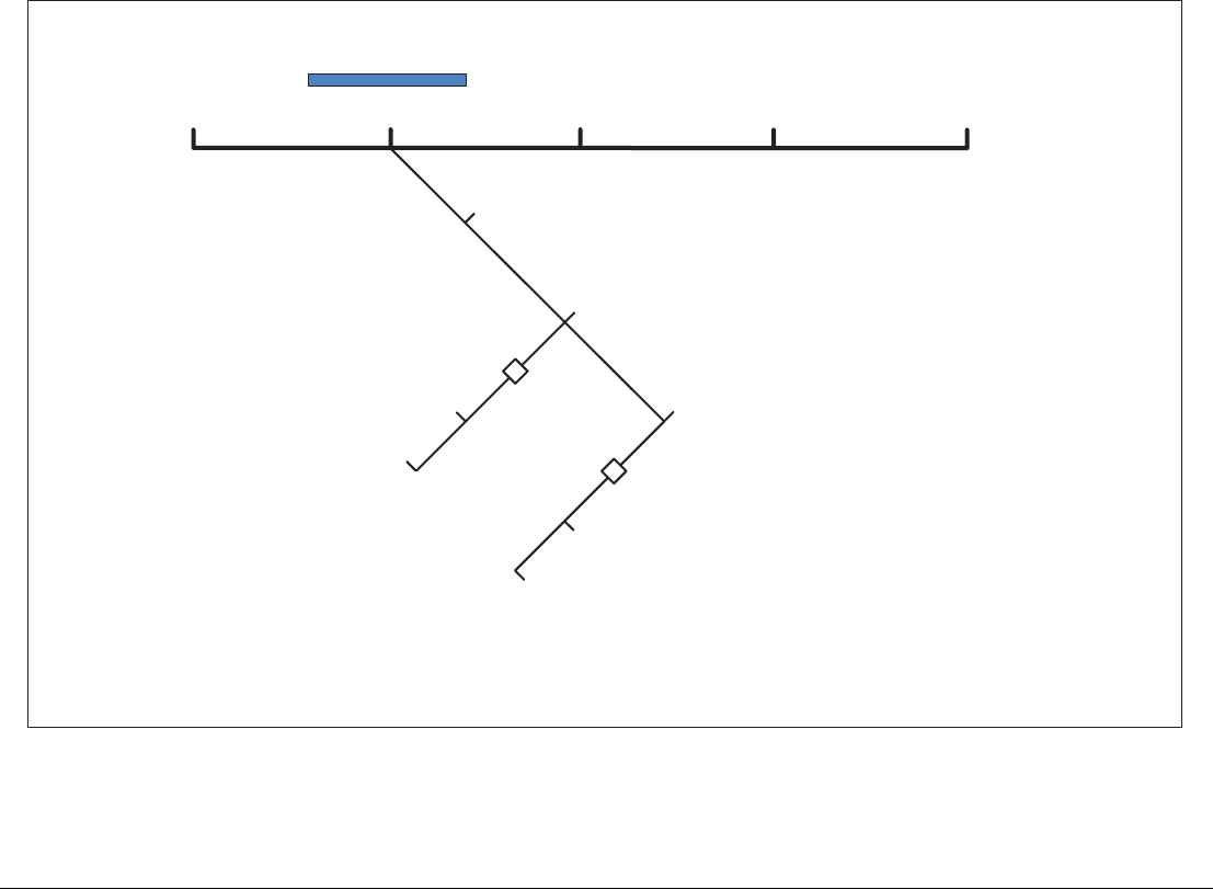
G-Series Reference Manual 50
5.5 Quick waypoints
The GOTO softkey gives you access to simple navigation functions on the G-Series system and opens the toolbars shown below.
You can place quick waypoints to navigate to from the default chart
toolbar using the GOTO softkey. This lets you set a temporary way-
point at the cursor position and track to it. When you reach the
waypoint, it is erased.
The waypoint you set is also visible on the radar display.
FIND GOTO ROUTES TRACKS PRESENTATION
Goto cursor
Follow route options
Route list
Follow route
Reverse and follow
Goto waypoint options
Waypoint list
Sort list
Goto waypoint
D10552-1

51 Chapter 5: The Chart Application
The WPTS/MOB button gives you access to more waypoint func-
tions. For information about using it, see Placing waypoints on
page 38.
Note: To set up and store a route consisting of more than one
waypoint, use the ROUTES softkey.
To navigate to the cursor position
1. Move the cursor to the appropriate position.
2. Press the GOTO softkey.
3. Press GOTO CURSOR.
A waypoint is placed at the cursor’s position and data sent to the
autopilot (if attached). See page 85 for more information.
Stored waypoints
You can navigate to a previously stored waypoint by selecting it
either on the chart with the cursor or from within the waypoint list.
To use the cursor to select a waypoint
1. Move the cursor over the waypoint.
2. Press GOTO WAYPOINT.
To select a waypoint from the waypoint list
1. On the Chart application toolbar, press GOTO.
2. Press GOTO WAYPOINT OPTIONS.
3. In the waypoint list, select the waypoint you want to navigate to.
4. Press GOTO WAYPOINT.
To stop navigating to a waypoint
1. Press STOP GOTO. (You must press STOP GOTO before you
start a new GOTO request.)
Resetting cross-track error
Restarting cross-track error (XTE) is useful if you find yourself off
track and want to set a direct course to the target waypoint, rather
than returning to your original track.
Resetting XTE sets a new course from your current position to the
target waypoint.
To reset XTE
1. While you are following a route or navigating to a waypoint,
press the RESTART XTE softkey.
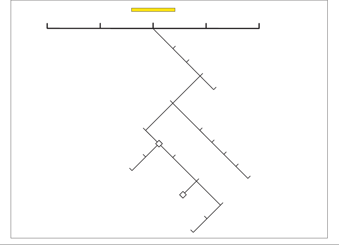
G-Series Reference Manual 52
5.6 Building a route
Using routes gives you more flexibility and planning options than the goto feature.
FIND GOTO ROUTES
Follow route options
Build new route
TRACKS PRESENTATION
Show/hide routes
Review and edit routes
Sort waypoint list
Insert waypoint
Use cursor
Make route
Place waypoint
Follow from here
Move waypoint
Save route
Goto waypoint
View and edit details
Place waypoint
Use waypoint list
Use waypoint list
Save route
Follow (quick) route
Sort list by
D10553-1
53 Chapter 5: The Chart Application
Use the ROUTES softkey to create and manage waypoints that
form part of a route. The ROUTES softkey gives you more flexibility
than the GOTO softkey; you can build a route for immediate use or
build and save a route for later use.
A route can consist of new waypoints, existing waypoints or a com-
bination of both. You can build routes in Chart view, or by selecting
waypoints from the waypoint list.
You can store up to 150 routes, each consisting of up to 50 way-
points. As you add each waypoint it is automatically assigned an
index number corresponding to its position in the route. It is repre-
sented on the chart by whichever waypoint symbol you have
specified.
• While a route is being built it is not active and does not affect
any current navigation.
• You can include a waypoint more than once in a route.
• You can create a new route when the route list is full but, upon
saving it, you will be prompted to choose an existing route to
overwrite.
• You cannot save a new route if any of the waypoints within it
are currently active: make an active route inactive if it contains a
waypoint you want to re-use in a new route.
• The way in which the OK and CANCEL buttons operate is dif-
ferent when you are building and editing routes (see below).
Building a route in chart view
The chart view lets you build a route from existing waypoints or by
placing new waypoints.
To build a route using new waypoints
1. Press the ROUTES softkey.
2. Select BUILD NEW ROUTE.
3. Position the cursor where you want to place a waypoint.
4. Press PLACE WAYPOINT.
5. Repeat steps 3-4 to build the set of waypoints needed for your
route.
6. Press SAVE ROUTE or FOLLOW (QUICK) ROUTE.
To build a route using existing waypoints
1. Press the ROUTES softkey.
2. Select BUILD NEW ROUTE.
3. Highlight the waypoint you want to use in your route.
4. Press USE THIS WAYPOINT.
5. Repeat steps 3-4 to build up your set of waypoints.
6. Press SAVE ROUTE or FOLLOW (QUICK) ROUTE.
Building a route from the waypoint list
To build a route from the waypoint list, you first need to place the
waypoints you will need.
To build a route using the waypoint list
1. Press the ROUTES softkey.
2. Select BUILD NEW ROUTE.
3. Press USE WAYPOINT LIST.
4. Select the waypoint you want to use in the route.
5. Continue to select waypoints until your route is complete.
Making changes to your route
If you make an error while building a route you can:
D8327_1
Sunday Trip
Waypoint
Route name
Route
destination

G-Series Reference Manual 54
• Undo the last waypoint (chart view only).
• Delete a waypoint from the route list (waypoint list only).
• Abandon the route build.
To remove waypoints from a route in chart view
1. Highlight the waypoint you want to remove from your route.
2. Press the UNDO WAYPOINT softkey.
The waypoint and the route to it are removed from the screen and
the cursor moves back to the previous waypoint.
To remove waypoints from a route in waypoint list view
1. Highlight the waypoint you want to remove from a route.
2. Press REMOVE WAYPOINT.
To abandon the route build completely
1. In chart view or in waypoint list view, press CANCEL.
2. Confirm by pressing YES.
Saving your route
Once you have built your route, you can:
• Save and immediately follow the built route.
• Save the route for later use (and rename it if required).
A route that is saved and immediately followed is referred to as a
Quick Route. If a Quick Route already exists, it is overwritten
unless you rename it (see page 58).
To save a route
1. Press the SAVE ROUTE softkey.
2. To assign the route a name and color, press the appropriate
softkey; press OK to accept the defaults.
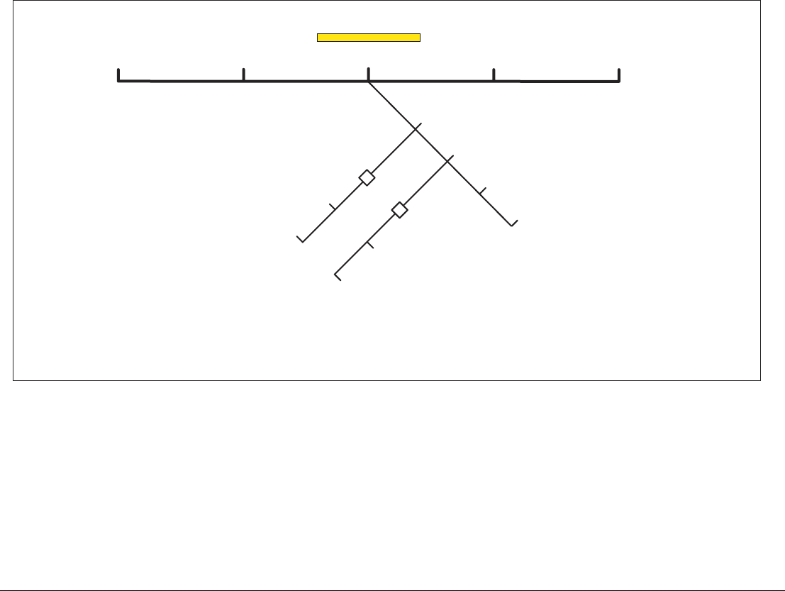
55 Chapter 5: The Chart Application
Following routes
You select a route to follow either by highlighting it with the cursor
or by selecting it within the routes list. When you begin to follow a
route it becomes active and is shown on all chart windows and on
all Nav Stations.
To select a route to follow with the cursor
1. Move the cursor over either the route line or waypoint symbol.
2. Press the FOLLOW THIS ROUTE or FOLLOW FROM HERE
softkey.
To select a route to follow in the routes list
1. Press either the GOTO or ROUTES softkey.
2. Press the FOLLOW ROUTE OPTIONS softkey.
3. On the Route List menu, select the route you want to follow.
4. Press the FOLLOW ROUTE or REVERSE AND FOLLOW
softkey.
To stop following a route
1. Press the STOP FOLLOW softkey.
FIND GOTO ROUTES
Follow route options
Build new route
TRACKS PRESENTATION
Show/hide routes
Review and edit routes
Route list
Route on chart show/hide
Waypoint index on/off Sort list by
Follow route
Reverse and follow
D10554-1

G-Series Reference Manual 56
Arriving at a waypoint
When the distance to the next waypoint in the route is less than that
specified for the arrival alarm radius (see page 194), or your boat
reaches the closest point of approach to the target (defined by a
line passing through the waypoint and perpendicular to the route
leg), a warning dialog is displayed and an alarm sounds (see
page 48).
When you acknowledge the alarm, the system selects the next
waypoint in the route and begins navigating to it.
Follow in reverse order
This option reverses the waypoint order (the last waypoint in the
route becomes the first) and renumbers the waypoints accordingly.
The route name moves to the reassigned first waypoint and then
the system automatically activates the reverse-follow route
function.
Advance waypoints
You can tell the system to ignore the next waypoint in your route,
and advance directly to the waypoint after it.
To skip the next waypoint
1. Highlight the route with the cursor, or press the GOTO softkey.
2. Press the ADVANCE WAYPOINT softkey.
Note: If the next waypoint is also the last in the route, pressing
ADVANCE WAYPOINT takes you to the first waypoint in the
route.
Cross-track error
Resetting the cross-track error (XTE) produces a new course from
your position to the target waypoint.
This is useful if you find yourself off course and want to go straight
to your target, rather than get back onto the original track.
Although RESTART XTE causes your vessel to change course, it
does not affect the saved route.
To restart cross-track error
1. With a route active, press the RESTART XTE softkey.
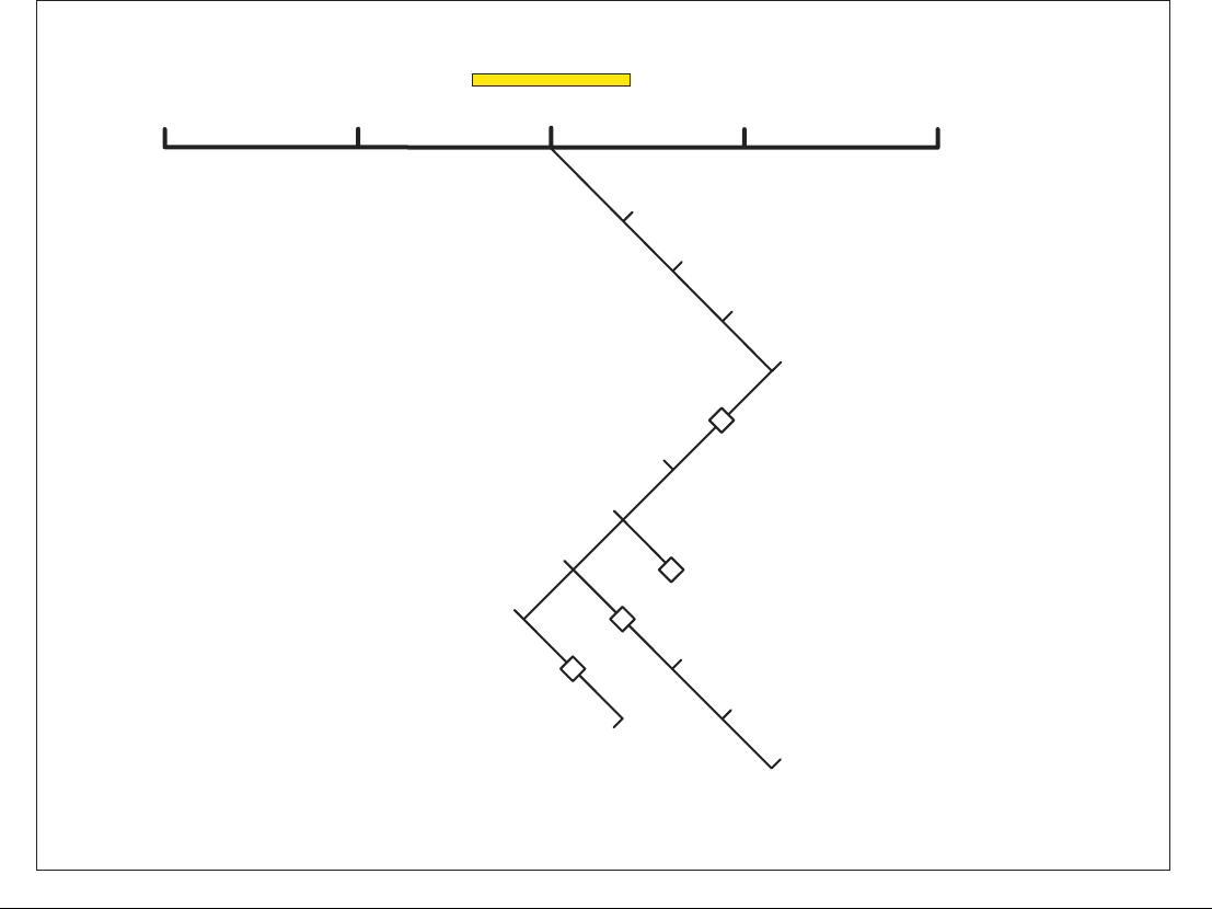
57 Chapter 5: The Chart Application
Editing routes
When you have built and saved a route, you can make updates or changes to it if necessary.
FIND GOTO ROUTES
Follow route options
Build new route
TRACKS PRESENTATION
Show/hide routes
Review and edit routes
Route list
Place waypoint
Erase route
Amend route course
Route details
Edit name and color Route name
Edit color
Edit route
Time ETA/hours
SOG actual/planned
Set SOG
D10555-1

G-Series Reference Manual 58
You can edit a route in a variety of ways. You can:
• Change the course of a route.
• Change the name of a route.
• Change the color of a route.
• Erase a route.
To select the route to edit
1. Highlight the route on the chart display using the cursor.
2. Press the REVIEW AND EDIT THIS ROUTE softkey.
or
1. Open the Routes List by pressing ROUTES followed by the
REVIEW AND EDIT ROUTES softkey.
Editing active routes
An active route is one that the system is currently following.
All parts of an active route can be edited, except for the current tar-
get waypoint. If a waypoint becomes active (becomes the waypoint
you are navigating to) while you are editing it, the system cancels
the edit and the waypoint’s details remain as originally set.
Adding waypoints
You can add existing waypoints to the route, or set up new way-
points and add them to the route.
To add an existing waypoint to the route
1. Press the AMEND ROUTE COURSE softkey.
2. Press the USE WAYPOINT LIST softkey.
3. In the right-hand column, highlight the position for the added
waypoint.
4. In the left-hand column, highlight the waypoint you want to add
to the list.
5. Press the INSERT WAYPOINT softkey.
6. Press the SAVE ROUTE softkey.
To create and add a new waypoint
1. Highlight the route you want to add a waypoint to.
2. Press the INSERT WAYPOINT softkey.
3. Move the cursor to the position of the new waypoint.
4. Press PLACE WAYPOINT.
Moving waypoints
When you move a waypoint, its new position is updated in all routes
that use it.
To move a waypoint
1. Highlight the waypoint you want to move.
2. Press the MOVE WAYPOINT softkey.
3. Drag the waypoint to its new position.
4. Press OK.
Removing waypoints
You can remove a waypoint from a route, as long as it is not part of
another route. If you try to remove a waypoint that is used in
another route, the system will warn you that it cannot be removed.
To remove a waypoint
1. Highlight the waypoint you want to remove.
2. Press the REMOVE WAYPOINT softkey.
Changing a route’s name or color
If you have many routes stored in your system, it can be useful to
give them individual names or mark them with a color of your
choice.
If the route was saved by the G-Series system with the name Quick
Route, changing its name will prevent it being overwritten by your
next quick route.

59 Chapter 5: The Chart Application
To change a route’s name or color
1. Select the route you want to edit.
2. Press the EDIT NAME AND COLOR softkey.
3. Select EDIT NAME or EDIT COLOR.
4. Make your desired changes to the route’s details.
5. Press OK.
Erasing a route
You can delete any route in your system except for the one that you
are following. When you erase a route the system deletes way-
points that are used by that route only. Waypoints that are used by
other routes are not deleted.
To erase a route
1. Select the route you want to delete.
2. Press the ERASE ROUTE softkey.
You can also erase all or selected routes, using the ARCHIVE &
TRANSFER function.
Timed routes
Details of all the routes you create are held in the Route List.
You can use the route list, in conjunction with the TIME and SOG
options, to display journey time in hours or as an ETA, and the SOG
as actual or planned.
If the route is active, the data is updated to show bearing, distance
and time from your current position.
To view TIME and SOG data
1. Select a route with the cursor or from the Routes List.
2. Press the ROUTE DETAILS softkey.
3. Toggle the TIME and SOG settings as required on the appro-
priate softkeys.
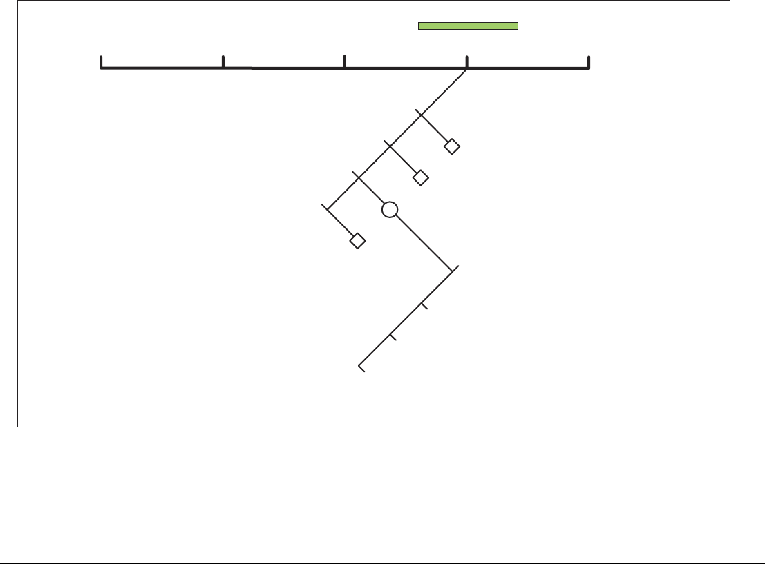
G-Series Reference Manual 60
5.7 Tracking your progress
The TRACKS softkey opens the toolbars shown below.
About tracks
A track is a line that shows the course of your journey. With tracks
enabled, the G-Series system stores track points as you progress
and automatically joins them up on screen to create the track.
You can save the track to review your journey at a later date or to
retrace it. You can convert a track to a route, enabling its use with
the navigation options of the chart application. You can save up to
15 tracks in the system, with 3000 track points in each.
FIND GOTO ROUTES
Create route from track
Start track
Review and edit tracks
TRACKS PRESENTATION
Show/hide tracks
Track list
Track list
Stop track
Discard track
Save track
Cancel stop command
Track starts
Track list
D10556-1

61 Chapter 5: The Chart Application
You can personalize track options to suit your requirements:
• Rename a track.
• Change the color of a track.
• Specify the time between track points.
• Specify the distance between track points.
Note: The smaller the track interval, the more points a track will
use.
Creating a track
There is a maximum number of tracking points that can be stored
by the G-Series system. It will warn you if your track uses the maxi-
mum number of track points and, if you continue to record your
track, start to overwrite the earliest track points with newer ones.
To start recording a track
1. Press the TRACKS softkey.
2. Press the START TRACK softkey.
To stop recording a track
1. Press the TRACKS softkey.
2. Press STOP TRACK.
3. Choose between SAVE TRACK and DISCARD TRACK.
Creating a route from a track
When a track is converted to a route, the system recreates the
course of your recorded journey using the minimum number of
waypoints.
Each waypoint created is saved with the depth and temperature
data (if applicable) for that position.
On completion, the maximum deviation of the route from the
recorded track is displayed and the new route is added to the route
list. You can use it in the same way as all your other routes.
Note: If the power fails while a track is being recorded, or if the
position fix is lost, a break will occur in the track. Only the
last contiguous segment of a track can be converted into a
route.
CAUTION: Before following the route, ensure that it is safe
for navigation, noting that it may deviate from your actual
path travelled.
To create a route from the current track
This method will take a ‘snapshot’ of the track to date, convert it to
a route and then continue laying the track:
1. Highlight the track with the cursor.
2. Press the CREATE ROUTE FROM TRACK softkey.
3. Press YES to give the route a name or NO to store the route
with the next default route number.
To create a route from a saved track
1. Press the TRACKS softkey.
2. Press the CREATE ROUTE FROM TRACK softkey to open the
Track List.
3. Select the track you want to convert.
4. Press CREATE ROUTE FROM TRACK again.
Editing and deleting tracks
To change the name and color of a track, or to delete a stored track,
you need to use the Review and Edit Tracks function. First you
select the track to edit or delete, then you make the changes you
want.
To select a track for editing
1. Highlight the track to edit on screen.
2. Press the REVIEW AND EDIT TRACKS softkey.
or
1. Open the Track List by pressing the TRACKS softkey followed
by the REVIEW AND EDIT TRACKS softkey.

G-Series Reference Manual 62
You can now choose to edit the name and color of the track, or to
delete it from the system.
5.8 Heading and course information
You can display a variety of graphical indicators to help monitor
your progress:
• HDG vector
• COG vector
• Wind arrow
• Tide arrow
• Course deviation indicator
Heading and course-over-ground vectors
Your vessel’s heading (HDG) is displayed as a line with an open
arrow head. It does not take account of winds or tides. The course
over ground (COG) indicator shows your vessel’s actual course. It
is displayed as a line with two open arrow heads.
The length of these lines is determined by the distance your boat
will travel in the time you have specified (3 mins, 6 mins or infinite)
in the Chart Setup Menu (see page 46) at the current speed.
Any times that you specify apply to all chart views and if INFINITE
is selected the vector will extend to the edge of the chart window.
Note: If either the speed over ground or heading data are unavail-
able, vectors cannot be displayed.
Wind and tide arrows
Wind and tides are displayed as lines with solid arrow heads in the
direction of the wind or tidal set. Wind arrows point into your boat
and tidal arrows point away. The width of the arrow indicates
strength.
For the wind arrows feature to work, you must have a wind instru-
ment enabled. For tide arrows, you need a GPS and speed through
water instrument.
To use graphical indicators (arrows)
1. Press the DATA button.
2. Press the CHART VECTORS softkey.
3. Toggle graphical indicators to the required setting on the appro-
priate softkeys.
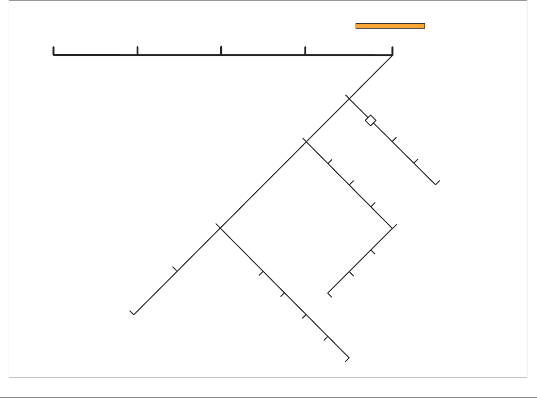
63 Chapter 5: The Chart Application
5.9 Presentation options
The PRESENTATION softkey gives you control over how data is displayed on a chart window. It opens the toolbars shown below.
FIND GOTO ROUTES
Chart view local/system
Declutter on/off
Chart layers
Chart mode and orientation
TRACKS PRESENTATION
Show/hide waypoints
Show waypoints
Show by sym/group
Aerial overlay
Radar overlay
Chart type
Chart symbology
AIS
Range rings
3D locator
On chart show/hide
Waypoint name on/off
Find
Chart sync
Orientation
Motion mode
Vessel offset
D10557-1

G-Series Reference Manual 64
5.10 Showing and hiding waypoints
This option lets you specify which waypoints are displayed on the
screen. You can show all waypoints, or display them by symbol or
group.
The latter options are useful if you have many waypoints placed in
a small area, which can clutter the chart.
Note: The show/hide status of a waypoint is a local setting and will
therefore only affect the individual display on which you are
working.
To show or hide waypoints by group or symbol
1. Press the PRESENTATION softkey.
2. Press SHOW/HIDE WAYPOINTS.
3. Toggle between SYM and GROUP on the SHOW BY softkey.
4. Select the relevant group and toggle its setting to SHOW or
HIDE on the ON CHART softkey.
To show or hide waypoint names
1. Press the PRESENTATION softkey.
2. Press SHOW/HIDE WAYPOINTS.
3. Toggle to the required setting with the WAYPOINT NAME
softkey.
To show or hide waypoint index numbers
1. Press the ROUTES softkey.
2. Press SHOW/HIDE ROUTES.
3. Toggle settings with the WAYPOINT INDEX softkey.
5.11 Chart layers
You can overlay data onto a chart window to give greater depth of
information. You can overlay radar, AIS or range rings.
Radar overlay
Overlaying the chart image with radar data allows for better distinc-
tion between stationary and moving objects. For best results,
switch on radar-chart synchronization.
You can customize the opacity setting for the overlaid image by
twisting the rotary controller.
If you have two radar scanners installed, select which one you want
to use for the overlay in the setup menu.
Note: A radar image cannot be overlaid onto a chart window if
dual-range is enabled in the radar application.
To switch radar overlay on or off
1. Press the PRESENTATION softkey.
2. Press CHART LAYERS.
3. Toggle radar overlay on or off with the RADAR OVERLAY
softkey.
To access radar and navigation options from the chart
application
1. Press OK twice.
2. Select RADAR options or NAVIGATION OPTIONS with the
appropriate softkey.
Using radar with the chart
You can combine the chart view with the following radar features:
• Radar range synchronization
• MARPA
• Radar overlay
Synchronizing chart scale with radar range
When synchronization is switched on:
• The radar range changes to match the chart scale.

65 Chapter 5: The Chart Application
• ‘Sync’ is indicated in the top left-hand corner of the chart
window.
• If you change the radar range in any radar window, all synchro-
nized chart views change scale to match.
• If you change the scale of a chart window, all radar windows
change range to match.
To set radar range synchronization
1. Press the PRESENTATION softkey.
2. Press the CHART MODE AND ORIENTATION softkey.
3. Select the appropriate synchronization mode on the CHART
SYNC softkey.
Note: Radar range synchronization is not available when the chart
motion mode is set to Autorange. The chart can be synchro-
nized with either the 3D chart or the radar but not both. You
cannot sync with radar if dual range is enabled in the radar
application.
Viewing MARPA targets on the chart
The Mini Automatic Radar Plotting Aid (MARPA) function is used
for target tracking and risk analysis. Although set up in radar mode
or radar overlay, all MARPA targets are displayed in the chart win-
dow, from which you can also access MARPA functions.
For detailed information about MARPA, see page 152.
To access MARPA controls from the chart application
1. Highlight a MARPA target with the cursor.
or
1. If radar overlay is switched on, press the RADAR OPTIONS
softkey.
2. Press the TARGET TRACKING softkey.
Radar options:
• Target tracking
• Gain
• Target display
• Change range (using the Range button)
Navigation options:
• Route
• Track
AIS
If you have an automatic identification system (AIS) fitted to your
vessel, you can use it to:
• Display the position of other craft which are appropriately en-
abled with AIS.
• Display broadcast AIS information from appropriately-equipped
vessels including position, course, speed, rate of turn and other
safety-critical data.
• Set up a safe zone around your vessel.
• Receive AIS alarms and safety-related messages.
This information is displayed in an overlay. Additional data, when
available, is displayed in a dialog box.
G-Series Reference Manual 66
For more information about how to use AIS, see Chapter 12:Auto-
matic Identification System on page 157.
To switch AIS overlay on or off
1. Press the PRESENTATION softkey.
2. Press CHART LAYERS.
3. Toggle the AIS LAYER setting to ON or OFF.
Range rings
Range rings give you an incremental representation of distance
from your vessel to help you judge distances at a glance. The rings
are always centred on your vessel, and the scale varies to suit your
current zoom setting. Each ring is labelled with the distance from
your vessel.
To turn range rings on or off
1. Press the PRESENTATION softkey.
2. Press the CHART LAYERS softkey.
3. Select RANGE RINGS ON/OFF.
5.12 Chart mode and orientation
Mode settings control how the chart displays information. You can
synchronize the chart display with the radar application; set how
movement is represented; set the position of your vessel’s repre-
sentation on-screen, and choose your preferred chart orientation.
Find
This is a shortcut softkey that has the same effect as the FIND key
on the default toolbar. It centers the chart display on either the cur-
sor or your vessel.
Orientation
Orientation settings control the way the chart is drawn in relation to
your vessel’s position and course.
North Up (N-up)
In North Up mode, the chart is static and oriented with true north
upwards. As your heading changes, the boat symbol rotates
accordingly. This is the default mode.
Heading Up (H-up)
In Heading Up mode, the on-screen representation of your vessel
remains static, with your current heading facing upwards. When
you change heading, the chart rotates accordingly.
You cannot select Head Up when the motion mode is set to True.
To prevent continual chart rotations as the boat yaws, the chart will
only update when your heading changes by at least 10 degrees.
D9056_1
097°T
11.6kt
1.237nm
00h04m33s
Safety
critical data
Heading
Large
vessel
Direction
of turn
Small
vessel
COG/SOG
vector
Safe zone (defined by
distance or time)
Dangerous
target (flashes)
Sleeping
target

67 Chapter 5: The Chart Application
Course Up (C-UP)
In Course Up mode, the chart is static and oriented with your cur-
rent course upwards. When you change heading, the ship symbol
moves accordingly. If you select a new course, the chart will reset
to display the new course upwards.
The reference used for Course Up depends upon the data available
at a given time. The system prioritizes data in the following order:
1. Bearing from origin to destination, i.e. intended course.
2. Locked heading from an autopilot.
3. Bearing to waypoint.
4. Instantaneous heading.
If heading data becomes unavailable while in this mode, a warning
message is shown and the chart shows 0° heading in relative
motion mode.
To set the chart orientation
1. Press the PRESENTATION softkey.
2. Select CHART MODE AND ORIENTATION.
3. Toggle to your preferred option on the ORIENTATION softkey.
Motion mode
The motion mode controls how your vessel’s progress relative to
the chart is represented on screen. There are three options on the
motion mode softkey:
• Relative motion (RM)
• True motion (TM)
• Autorange (AR)
When you pan the chart or use Find Cursor, the motion mode is
suspended. This is indicated in the status bar by putting the motion
name in parentheses. Manually changing the range in autorange
also suspends motion mode.
When a chart window is set to SYSTEM view the motion mode will
be set but not synchronized across other system view windows.
Relative motion
The default motion mode is relative motion. In this mode, the chart
is redrawn relative to your position as you make progress, so that
your vessel is always shown in the same place on the screen. The
position in which your boat is shown on-screen can be altered with
the vessel offset option.
True motion (TM)
When the motion mode is set to true motion, the chart view
remains static and your vessel is shown moving across it as you
make progress. As your position approaches the edge of the
screen, the chart display is redrawn to include the area ahead of
you.
You cannot select True Motion when the orientation is set to Head
Up.
Autorange
Autorange selects and maintains the largest possible scale of chart
that will display both your vessel and your target waypoint. Autor-
ange is not available if radar-chart synchronization is on.
Relative motion with optional vessel offset
In relative motion mode you can specify whether the boat is fixed in
the centre of the window (0 offset, default) or offset by 1/3 or 2/3.
The latter options give you a greater view ahead of your position.
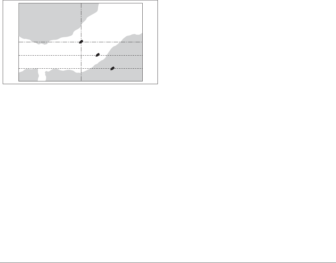
G-Series Reference Manual 68
5.13 Chart view
The chart application defaults to system view which means the fol-
lowing settings apply to all nav stations in your system:
• Chart mode and orientation
• Chart layers (aerial, radar, 3D locator and AIS)
• Synchronization (radar/chart and 3D/chart)
• Show/hide waypoints, routes and tracks
• Declutter
• Vectors
If you change any of these options in one window, ALL system win-
dows will update.
When local chart view is selected the presentation for each window
is set independently.
To define how the chart windows are presented
1. Toggle between LOCAL and SYSTEM on the CHART VIEW
softkey.
5.14 Chart detail
You can adjust the level of detail shown on the chart by choosing to
show or hide certain features.
To show or hide routes and tracks
1. Highlight a route or track and press the HIDE softkey.
or
1. Open the Route or Track list.
2. Highlight a route or track in the list.
3. Toggle between SHOW and HIDE settings with the ROUTE ON
CHART or TRACK ON CHART softkey.
Note: The active route is always displayed irrespective of the
display status.
Decluttering the chart view
Sometimes a large number of cartographic objects in a particular
area can render the chart view difficult to read. You can reduce the
amount of detail by de-cluttering the chart display. Turning declutter
on hides the following cartographic objects:
• Text
• Chart boundaries
• Spot soundings
• Depth contours
• Light sectors
• Caution and routing data
• Land and marine features
• Business services (if available on your cartography)
To turn declutter on or off
1. Press the PRESENTATION softkey.
2. Toggle between ON and OFF with the DECLUTTER softkey.
D6839_3
0 Vessel offset
1/3 Vessel offset
2/3 Vessel offset

69 Chapter 5: The Chart Application
If decluttering does not hide a particular feature, you can hide fea-
tures individually from the Cartography Setup menu.
5.15 Journey planning
Navionics chart data is preinstalled on the GPM400. The data pro-
vides you with some or all of the following information:
• Details for cartographic objects, including source data for struc-
tures, lines, open sea areas etc.
• Details of ports, port and business services.
• Tide and current information.
• Wrecks and obstructions.
• Panoramic photos.
• Aerial photographs.
• Pilot books.
• Coastal roads.
• For full details of the features available, refer to the Navionics
website at www.navionics.com or www.navionics.it
Some Navionics data provide detailed bathymetric information in
addition to standard chart information. You can choose between the
standard chart view, or the view displaying bathymetric contours.
To display bathymetric information
1. Press the PRESENTATION softkey.
2. Press the CHART LAYERS softkey.
3. Press the CHART TYPE softkey to toggle between FISH and
NAV options.
• The FISH option displays bathymetric information.
• The NAV option displays the standard chart view.
If you select FISH and no data is available for your current position,
the databar displays (FISH) to indicate that you are in that mode
but without data.
Displaying details for objects and features
Many objects shown on the chart have detailed information associ-
ated with them. Some of this information displays automatically
whenever you highlight the object with the cursor.
Depending on the object type, its additional information might allow
you to:
• Locate the nearest waypoint, port, port service, tidal and current
stations, wreck or obstruction, to the selected position.
• Search for a named port.
• View detailed data for the selected port, tidal station or current
station.
• View panoramic photographs.
To view detailed object information
1. Move the cursor over an object. If basic information exists for
the object, it will be displayed (unless deactivated in the setup
menu).
2. Press OK.
3. Detailed information for the object is displayed.
To change the set-up options for object information, see page 46.
Finding nearby features and services
You can locate the nearest waypoint, port, port service, tidal and
current stations, wreck or obstruction, to the cursor position.
To find nearby features and services
1. Move the cursor to the relevant position.
2. Press OK.
3. Press the FIND NEAREST softkey.
4. Select the appropriate options from the on-screen lists.
Once located, you can use the softkeys and trackpad to:
• Display detailed data for services at the listed ports.
• Show the selected item on the chart.
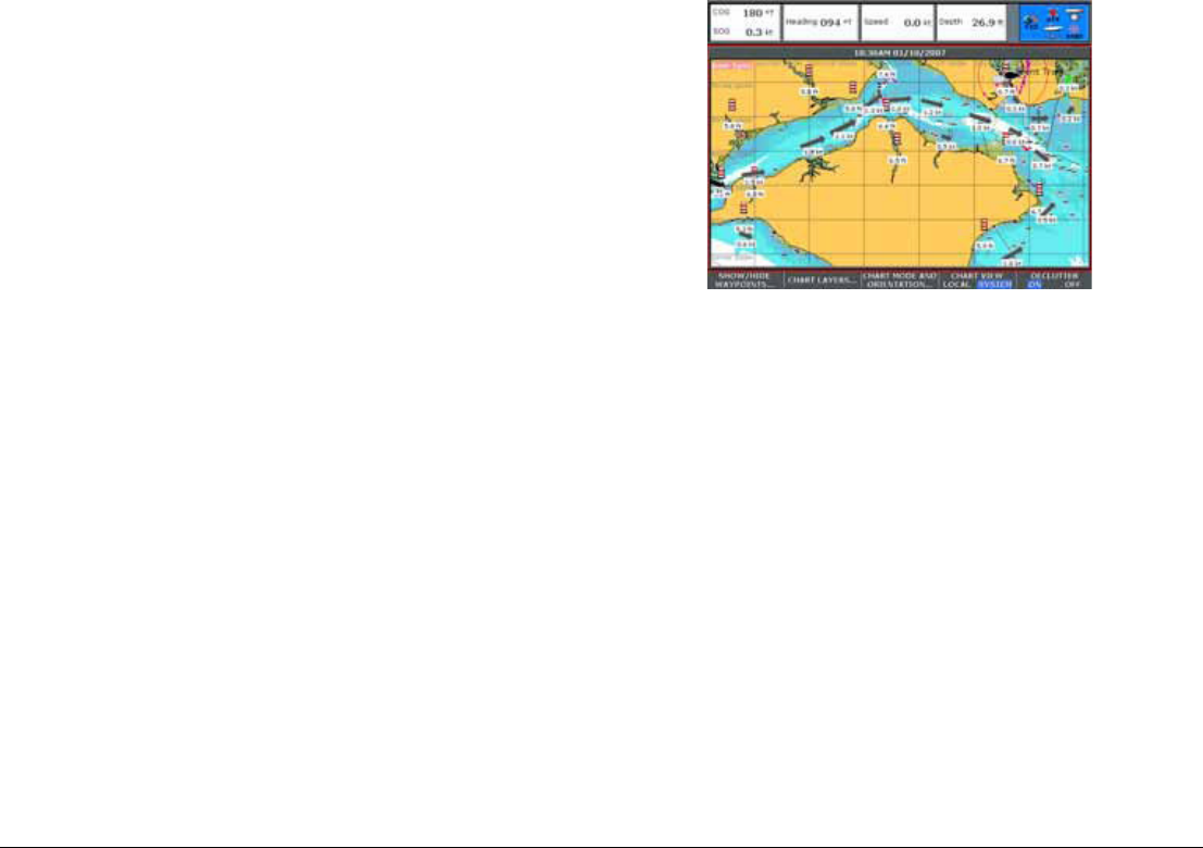
G-Series Reference Manual 70
• GOTO the selected waypoint.
• View tidal/current data for the selected tidal/current station.
Static tide and current data
You can display tide and current information using the FIND NEAR-
EST function. Alternatively, you can display tide and current data by
highlighting the appropriate diamond on screen.
This method provides information including tidal and current
curves, and lets you select data by date and time.
To show data using tide and current diamonds
1. Highlight the appropriate diamond with the cursor.
2. Press OK.
3. Press the DATA softkey.
Animated tide and current data
Animated tide and current data is available. The animations provide
a visual cue to the movement of currents and tides for times you
specify.
You can set the date for the animation and choose to see the whole
animation from the beginning or start it at any point within a 24-hour
period. You can also choose to view the animation continuously or
to step through it incrementally.
To view animated tide and current data
1. Highlight a tide or current diamond.
2. Press OK.
3. Press the ANIMATE softkey.
The Tide/Current Animation screen opens with animation paused.
• Press the ANIMATION PLAY/PAUSE softkey to start
animation.
The time and date of the animated data are displayed on the status
bar; the animation starts from the current time.
Controlling animation
When you open the Tide/Current Animation screen, the toolbar pro-
vides softkeys to stop and start the animation; step the animation
forwards or backwards in time; set the size of the step, or select a
date for the animation.

71 Chapter 5: The Chart Application
The animation plays in a loop: when it reaches the end of a 24-hour
animation period, it starts again at the beginning.
To start or stop the animation
1. Press the ANIMATION PLAY/PAUSE softkey.
To view the animation in steps
1. Press either the STEP BACK or STEP FWD softkey.
To set the step interval
1. If the animation is playing, press PAUSE.
2. Press the SET TIME INTERVAL softkey.
3. Use the rotary controller to adjust the time interval (within the
range of 15 to 120 minutes).
4. Press OK or CANCEL to save the new interval.
To set the animation date
1. Press the SET DATE softkey:
2. Press OK to save the new date and return to the Tide/Current
Animation screen, which will update to display the tide or
current for the date you chose.
Press CANCEL to ignore the date change and go back to the Tide/
Current Animation screen, leaving the date setting unchanged.
Port services
You can display details of port services by using the FIND NEAR-
EST function. Alternatively, you can use either of the methods
below.
To display port services
1. Highlight a port symbol.
2. Press OK.
3. Highlight a service.
4. Press the VIEW DETAILS softkey.
or
1. Press OK.
2. Press the SEARCH BY NAME softkey.
3. Press EDIT NAME.
4. Enter the port name (or the first few characters of the port
name).
5. Press SEARCH.
6. If the search returns more than one port, select the port you are
interested in.
7. Select your service.
8. Press the VIEW DETAILS softkey.
Pilot book information
The pilot book information option enables you to view detailed infor-
mation normally contained in a nautical pilot book.
To view pilot book information
1. Highlight a port symbol.
2. Press OK.
3. Select Pilot Book and press VIEW PILOT BOOK.
4. Use the toolbar to navigate around the pilot book.
TODAY’S DATE Set the animation date to the current date.
PREV DATE Set the animation date to 24-hours previous to
current date.
NEXT DATE Set the animation date to 24-hours ahead of
current date.
EDIT DATE Opens the Edit Date pop-up screen: use the
trackpad or rotary controller to enter the date you
want to see an animation for.
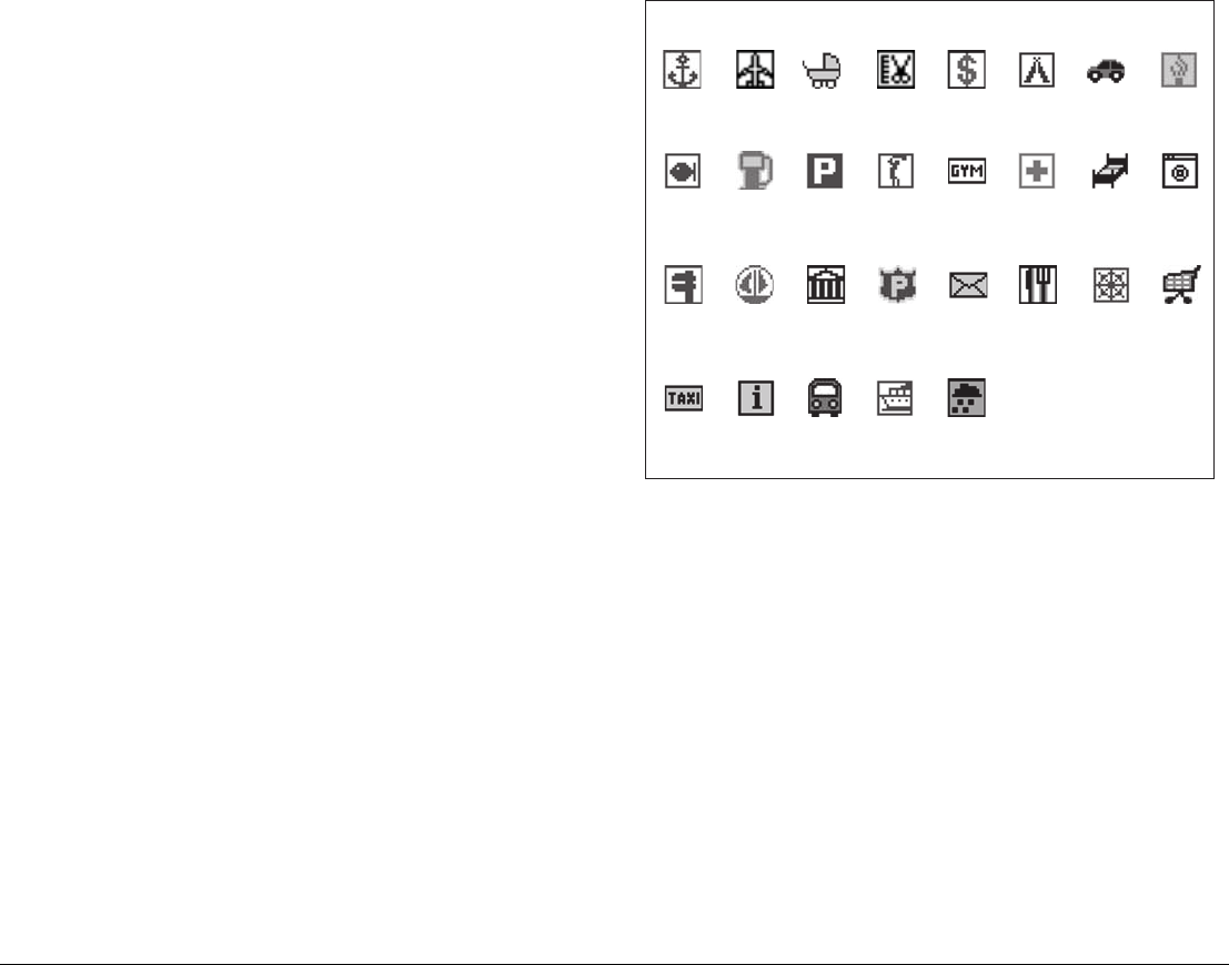
G-Series Reference Manual 72
Panoramic photography
You can view panoramic photography of many ports and marinas.
The availability of photography is indicated by a camera symbol on
the chart, placed at the point the photograph was taken. The view-
point is indicated by the angle of the camera symbol. You can also
access photography from port services information.
To display panoramic photography
1. Highlight a port symbol.
2. Press OK.
3. In the Object Info popup, select Photos.
4. Select a numbered photograph from the list.
5. Press the VIEW PHOTO softkey.
or
1. Hotspot a camera symbol.
Business services and points of interest
The location of various business services and points of interest are
indicated by the following symbols: Highlighting any of the above service symbols gives you the follow-
ing information about the business:
• Name
• Address
• Telephone number
• Type of business
You can switch off the business services symbols from the Cartog-
raphy Setup Menu, or by switching on chart declutter.
Aerial photography
Aerial photography is available for navigable waters up to three
miles inland. Beyond that, land is shown in green (on color charts)
and in gray (on black-and-white charts).
Business services/points of interest symbols
Airport Babysitting Barber Bank Camping Car hire
Fishing
equipment
Parking
Firemen
Gas/Petrol
PortNautical
repairs
LaundryHotelHospitalGym
Golf
Post OfficePoliceMuseum
Anchorage
Water
transport
TrainTourist
information
Taxi
station
ShopShip
repairs
Restaurant
Weather
station
D8226_1

73 Chapter 5: The Chart Application
To overlay aerial photography
1. Press the PRESENTATION softkey.
2. Press CHART LAYERS.
3. Toggle AERIAL OVERLAY to ON or OFF as appropriate.
4. Use the rotary controller to adjust overlay opacity.
Overlay opacity
The opacity level controls how visible the underlying chart view is
with photography overlaid. The higher the setting, the stronger the
overlay.
Overlay area
You can specify whether the aerial photographic overlay is dis-
played for land areas only, or for land and sea areas.
•On Land displays a normal chart view for sea areas and over-
lays aerial photography on areas of land. This can help you
interpret your surroundings while keeping important navigation-
al data visible.
•On Land and Sea displays aerial photography of both land and
sea areas. This can help you distinguish between deep and
shallow water (dark blue and light blue, respectively), and to
view land features simultaneously.
To specify the overlay area
1. Open the Cartography Setup Menu.
2. Select Aerial Photo Overlay.
3. Choose your preferred setting.
5.16 Measuring distance, range and
bearing
Options for measuring distance, range and bearing are outlined in
the table below.
Cursor position
You can determine the exact position, distance and bearing to the
position of the cursor by referring to the cursor position (Csr Pos)
data in the databar.
Ruler
The chart application includes a ruler which accurately measures
the distance and bearing between two points.
To use the ruler
1. Position the cursor at the start-point of the measured distance.
2. Press the DATA button.
3. Press the RULER softkey.
4. Move the cursor to the end-point of the measured distance.
5. Press OK.
To move the ruler
1. To move the start-point, press ADJUST A.
2. To move the end-point, press ADJUST B.
Functions
Distance
between
points
Range from
vessel Bearing
Range Rings Yes (approx.) Yes (approx.) -
Cursor position - Yes Yes
Ruler Yes Yes

G-Series Reference Manual 74
To clear the ruler
1. Press DATA.
2. Press the RULER softkey.
3. Press CLEAR RULER.

6
Chapter 6: 3D Chart
The 3D chart gives you an accurate, three-dimensional view of the area around your vessel. This can help
you navigate more confidently if the area is new to you or if visibility is poor.
Navigation functions are available in the 3D chart.
Chapter contents
• 6.1 Safety notice on page 76
• 6.2 3D chart requirements on page 76
• 6.3 Setting up the 3D chart on page 76
• 6.4 The 3D chart view on page 76
• 6.5 Operation modes on page 77
• 6.6 Using the 3D chart on page 78
• 6.7 Presentation options on page 80
• 6.8 Tuning the view on page 81
• 6.9 Using the standard and 3D charts together on page 83
• 6.10 Aerial photography overlay on page 84
See also…
•The Chart Application on page 43
•Using Waypoints on page 35

G-Series Reference Manual 76
6.1 Safety notice
The 3D chart is an aid to visualization only. Always check your nor-
mal charts to ensure your route is safe.
Until you are familiar with interpreting the 3D chart display, take
every opportunity to compare what you see on-screen with your
actual surroundings. Practice harbour and coastal navigation dur-
ing daylight hours and in clear weather conditions.
You can use the 3D chart in simulator mode to help you gain
experience.
Before you use the 3D chart, read Chapter 4:Using Waypoints on
page 35 and Chapter 5:The Chart Application on page 43 for infor-
mation about reading chart information and using the G-Series
system navigation functions.
6.2 3D chart requirements
For the 3D chart application to operate correctly, the G-Series sys-
tem requires heading and position data.
6.3 Setting up the 3D chart
The 3D chart setup menu is available from the system setup menu.
For information on using the system setup menu, see To change a
menu setting on page 23.
The 3D chart setup menu gives you the following options:
6.4 The 3D chart view
An overview of the 3D chart window is given below.
CAUTION
The 3D chart is not a substitute for good navigational
practice, nor does it remove the need to use official
government paper charts. Do not use the 3D chart before
you have read this chapter.
FUNCTION
Description
OPTIONS
(Default in bold)
Centre-of-view indicator
Centre-of-view indicator (marked with a white cross)
ON
OFF
Vessel symbol
Style of boat symbol displayed on-screen
Sail
Power
Vessel Size
Size of boat symbol displayed on-screen
Tiny
Small
Medium
Large
Huge
Aerial Photo Overlay
Overlay an aerial photograph on the 3D chart
ON
OFF
Chart Text
Text viewed on the 3Dchart
ON
OFF
Nav Marks
Navigation marks viewed on the 3D chart
ON
OFF
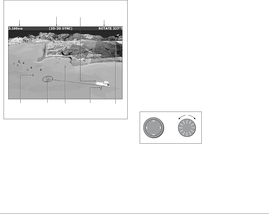
77 Chapter 6: 3D Chart
The 3D chart view includes the same cartographic objects and nav-
igation features, like waypoints, as the standard chart. To move
around the 3D chart, and to display your chosen area at the
required scale, use pan and zoom as normal.
In the 3D chart, you can also adjust rotate and pitch settings.
•Rotate rotates the view between 0° and 359°.
•Pitch adjusts the vertical angle of view between 1° and 90°.
6.5 Operation modes
You can choose to view the chart in one of two modes:
• Active motion mode.
• Planning mode.
Active motion mode
This is the default mode. The screen shows an aerial view of the
3D chart with a viewpoint from above your boat, slightly behind it
and looking forward. As your position changes, the chart view auto-
matically updates.
You can set different viewpoints: see View options on page 81.
Rotating or panning the chart puts it into planning mode.
Planning mode
If you move the view away from your current location, the system
enters planning mode. You can view areas from different angles,
bearings and ranges but your vessel is no longer kept on screen
automatically.
The same controls and functions are available in both modes.
To enter planning mode:
• Pan to the area of the chart that
you want to view or
• Turn the rotary control (except
if set to CENTRE and ADJUST
PITCH).
Planning mode is indicated in the status bar by brackets around the
mode: (FWD).
Mode
Shows mode
application is
working iin.
Rotation
Shows in degrees true,
how far the on-screen
view has been rotated
from your boat's heading.
Range
Horizontal distance across
screen (halfway up the window
or at center of view). Shown in
selected system units.
Boat symbol
Boat's position on
chart. Select sail
or power boat.
Center-of-view
White cross indicates
center of chart view
at sea level.
North arrow
3D indication of True
North in relation to
the chart view.
Depth scale
Approximate
depth beneath
your boat.
Waypoint
With arrival
circle
Cartographic objects
Select objects for display
via the 3D Chart Setup
menu.
D8250_1
Or
D8737_1
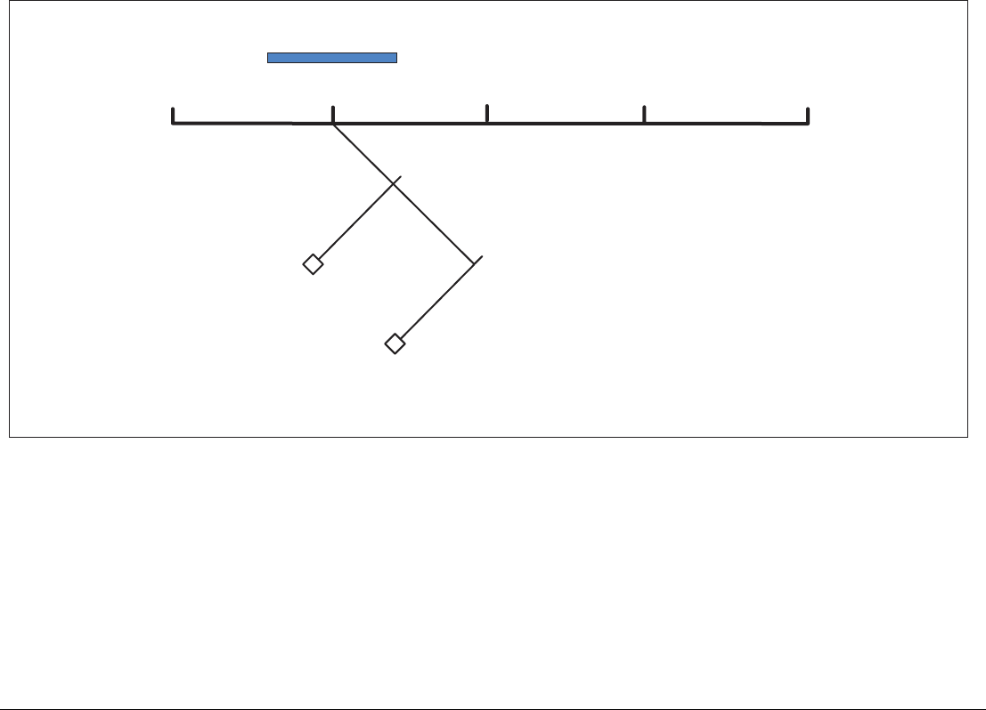
G-Series Reference Manual 78
6.6 Using the 3D chart
The default toolbar on the 3D chart gives you access to navigation and presentation options.
Find Ship
Pressing the FIND SHIP softkey redraws the chart about your cur-
rent location, with your vessel in view and facing forwards.
Adjusting the chart view
The default toolbar includes two softkeys dedicated to adjusting the
view of the 3D chart application. ADJUST lets you rotate the view
and adjust the angle (pitch). ADJUST ON sets the reference point
for view settings: either on the center of the image, or on the virtual-
eye position.
To adjust rotate and pitch settings
1. Press the ADJUST softkey.
FIND SHIP GOTO ADJUST ON
EYE CENTER
Route list
Waypoint list
ADJUST
ROTATE PITCH PRESENTATION
Follow route options
Goto waypoint options
D10558-1
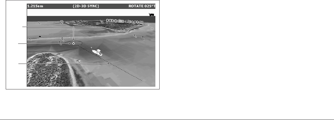
79 Chapter 6: 3D Chart
2. Toggle to the setting you want to adjust.
3. Make the adjustment with the rotary controller.
4. Press OK.
Note: The rotary controller is always active to adjust pitch and
rotation. This is different to most other uses of the rotary
controller, which require you to press a softkey to enable
adjustment.
To set the adjustment reference point
1. Press the ADJUST ON softkey.
2. Toggle to EYE or CENTER as required.
3. Press OK.
Navigation options
Shortcuts to the Route List and Waypoint List are available under
the GOTO softkey. For information about using them, see page 50.
Routes and waypoints can only be edited from within the standard
chart application, but changes made on the standard chart are
reflected on the 3D chart.
D8258_2
Active
waypoint
Course
of route
Waypoint
arrival
circle
G-Series Reference Manual 80
6.7 Presentation options
The PRESENTATION softkey opens the toolbars shown below:
Chart layers
3D view options
View to forward/starboard/aft/port
Trans cone on/off
Depth scale on/off
Adjust exaggeration
Waypoint name on/off
Depth overlay on/off
Depth plane value
Waypoint name on/off
FIND SHIP GOTO ADJUST ON
EYE CENTER
ADJUST
ROTATE PITCH
PRESENTATION
D10559-1
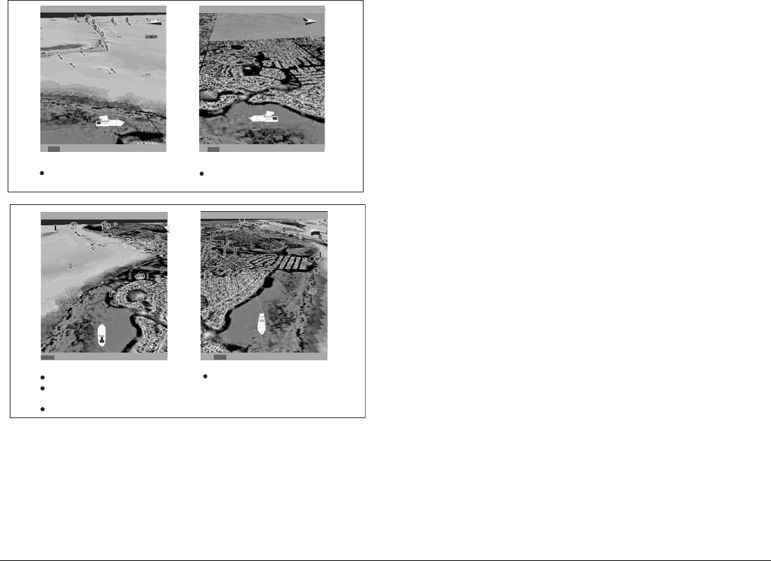
81 Chapter 6: 3D Chart
View options
There are four view options to choose from: forward, aft, port and
starboard.
The current option is highlighted on the toolbar and displayed in the
status bar.
To select the view option
1. Press the PRESENTATION softkey.
2. Press the 3D VIEW OPTIONS softkey.
3. Toggle to your preferred view on the VIEW TO softkey.
4. Press OK.
Multiple views
You can display multiple 3D chart views by creating a page that
contains up to four windows. Each window could contain a view of:
• The same area from a different angle.
• Up to four different areas of the chart.
For information about setting up application windows, see Selecting
application windows on page 26.
6.8 Tuning the view
You can tune the 3D chart view using the following features:
• Exaggeration
• Declutter
AFTPRT
PRT ROTATE 106oT2.431nm
Eye point above and to starboard side
of boat, looking to port.
STB ROTATE 280oT2.431nm
AFT
D8726_1
STB
Eye point above and to port side of
boat, looking to starboard.
Port Starboard
FWD ROTATE 195oT2.431nm
FWD
Default view.
Eye point above and behind the boat,
looking forward.
Pressing FIND SHIP resets to this view.
AFT ROTATE 011oT
Eye point above and in front of the boat,
looking behind it.
D8725_1
AFT
2.431nm
Forward Aft
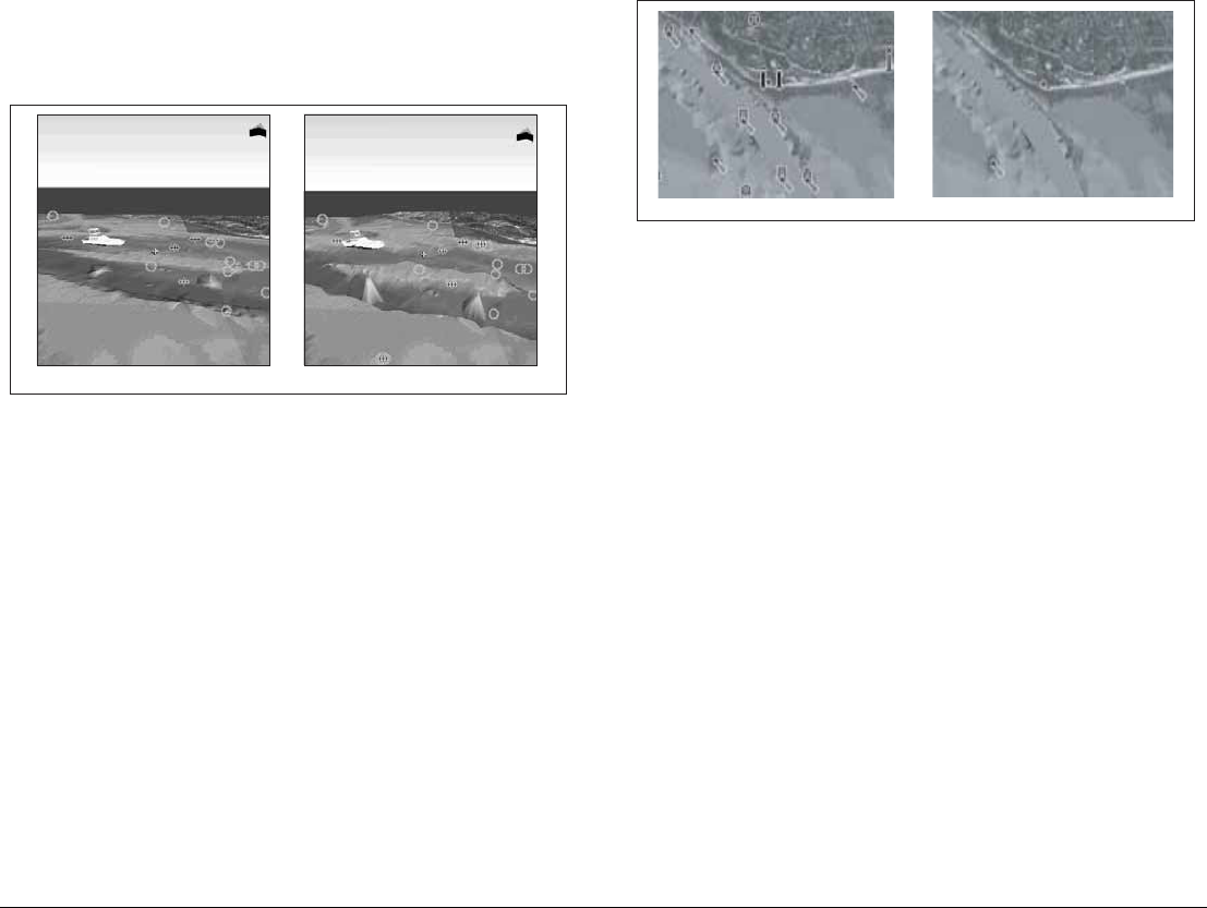
G-Series Reference Manual 82
Exaggeration
Sometimes it is easier to see certain topographical features if they
are exaggerated. Adjusting the exaggeration has the effect of verti-
cally stretching objects on the chart, making it easier to see their
shape and position. This could be particularly helpful if you are fish-
ing, for example.
To adjust exaggeration
1. Press the PRESENTATION softkey.
2. Press the 3D VIEW OPTIONS softkey.
3. Press ADJUST EXAGGERATION.
4. Use the rotary controller to set your level of exaggeration.
5. Press OK.
Press CANCEL at any time to return to the previous exaggeration
setting.
Declutter
In some circumstances, the quantity of information displayed on the
chart can render its interpretation difficult.
The declutter feature removes some chart objects from view to
make the chart clearer to read and navigation simpler.
To turn declutter on or off
1. Press the PRESENTATION softkey.
2. Toggle to ON or OFF using the DECLUTTER softkey.
Exaggeration factor x1 Exaggeration factor x50
D8253_2
Declutter ONDeclutter OFF
D8254_1
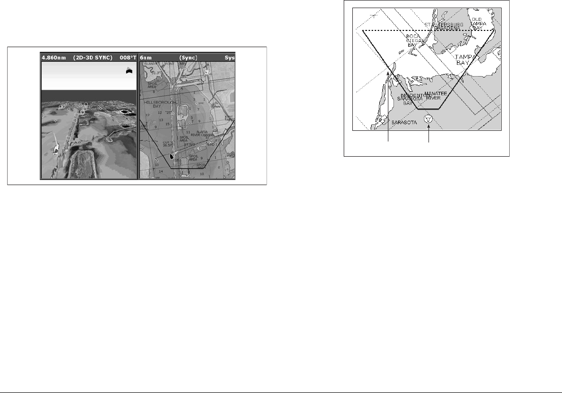
83 Chapter 6: 3D Chart
6.9 Using the standard and 3D charts
together
If the area in which you are navigating is unfamiliar, or visibility is
poor, working with standard and 3D chart windows side-by-side can
give you extra confidence and information. With the charts dis-
played side by side, a comprehensive view of the surrounding area
is available.
As with all multiple page sets, the active window is indicated by a
red border. To make changes to an application it must be in the
active window.
For information about setting up a page set to view two applications
together, see page 25.
3D view locator
The view locator is a polygon displayed on the standard chart which
outlines the boundaries of the area shown on the 3D chart. It is
shown as a blue line extending from the virtual eye point icon.
As you rotate, adjust pitch, pan or zoom the 3D chart view, the loca-
tor updates on the standard chart.
To display the 3D view locator
1. Make a standard (two-dimensional) chart window active.
2. Press the PRESENTATION softkey.
3. Press the CHART LAYERS softkey.
4. Toggle the 3D LOCATOR setting to ON.
5. Press OK.
Chart synchronization
Chart synchronization enables you to synchronize heading, range
and position information on the standard and 3D charts.
When chart synchronization is ON:
• 2D/3D synchronization is flagged in the status bars.
D8255_1
D8256_1
View locator Eye point icon
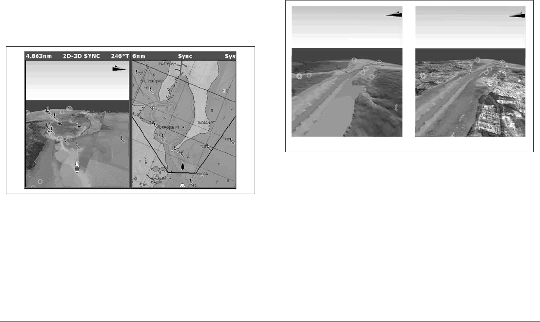
G-Series Reference Manual 84
• Pressing FIND SHIP from any synchronized application returns
the 3D chart to the default view and synchronizes the 2D chart to
the same view.
• Changes made to heading, range or position in either 2D or 3D
charts are reflected in both windows.
• If the 2D chart view for the current window is set to SYSTEM,
any changes made in a chart window will be reflected in all win-
dows on all displays.
• If the 2D chart view for the current window is set to LOCAL, no
other windows will be affected.
• You can synchronize the 2D chart with the 3D chart or the radar
but not both.
To synchronize the standard chart with the 3D chart
1. Make a 2D chart window active.
2. Press the PRESENTATION softkey.
3. Press CHART MODE AND ORIENTATION.
4. Toggle the CHART SYNC mode to 3D.
5. Press OK.
6.10 Aerial photography overlay
You can overlay aerial photography onto the 3D image. This can
help you interpret the chart view of your surroundings. Aerial pho-
tography is available for the navigable waters up to three miles
inside the coastline. Beyond these limits, land appears green (on
color charts) or grey (on black-and-white charts).
• Aerial photo overlay is controlled from the 3D chart Setup
Menu.
D8257_1
Standard 3D image 3D image with aerial overlay
D8848_1

7
Chapter 7: Autopilot Integration
If you have a Raymarine autopilot installed, you can access some of its functions from the G-Series
keyboard.
The autopilot functions do not replace the autopilot control head. You must have a pilot control
head installed before you enable or engage the autopilot.
Chapter contents
• 7.1 Emergency disengage on page 86
• 7.2 Enabling and engaging the autopilot on page 86
• 7.3 Autopilot Status Indicator on page 86
• 7.4 The autopilot control screen on page 87
• 7.5 Waypoint arrival on page 87

G-Series Reference Manual 86
7.1 Emergency disengage
To disable the autopilot
1. Press the STANDBY button.
7.2 Enabling and engaging the
autopilot
To allow the system to control autopilot functions, first enable auto-
pilot control on the setup menu. The default autopilot setting is
disabled.
If you are navigating to a waypoint or following a route, you can see
information for it on the Pilot Control pop-up window. This pop-up
gives you softkeys to set the pilot to auto, track or standby.
Whenever you initiate a GOTO or FOLLOW ROUTE, the pilot pop-
up gives you a softkey to engage pilot.
To enable autopilot control
1. Press the MENU button to open the Setup menu.
2. Select System Setup > System Integration > Autopilot
Control.
3. Select Enabled.
4. Press the OK button.
To open the pilot control screen
1. Press the PILOT button.
If you press OK or CANCEL without engaging the autopilot, you go
back to the navigation screen with the autopilot disengaged.
When the autopilot is engaged, or you hotspot an active route or
waypoint, the toolbar gives you the following options:
Note: You can only perform individual advance waypoint opera-
tions: it is not possible to perform one track command for
multiple advance waypoints.
To disengage the autopilot
1. Press the STANDBY button.
or
1. Use the softkeys provided with the Pilot Control pop-up screen.
7.3 Autopilot Status Indicator
An indicator in the top-right corner of the display gives you the cur-
rent status of the autopilot.
STOP GOTO/FOLLOW Opens the Pilot Control screen. If the
autopilot is in track mode, the route
complete alarm sounds.
ADVANCE WAYPOINT Opens the Pilot Control screen and
provides the AUTO and TRACK softkeys.
The screen stays open until you choose
either AUTO or TRACK.
Icon Autopilot mode
Standby.
Track.
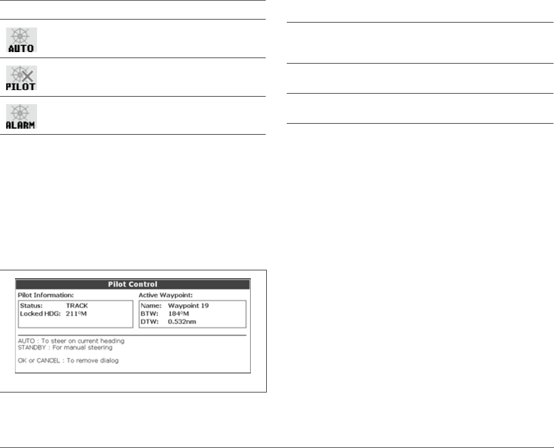
87 Chapter 7: Autopilot Integration
7.4 The autopilot control screen
The Pilot Control pop-up screen is displayed when you engage the
autopilot in track mode, at waypoint arrival, or when you select it via
the Pilot key or from the Setup Menu. It gives you:
• Autopilot status
• Live navigation information
• Toolbar with softkeys to control the autopilot
Autopilot toolbar
To close the Pilot Control pop-up without activating AUTO or
TRACK, press OK or CANCEL.
7.5 Waypoint arrival
when there are more waypoints in your route, the system:
• sounds the waypoint arrival alarm
• displays the Pilot Control screen, with information about the
next waypoint
The toolbar gives you four options:
Press the ENGAGE PILOT -TRACK- softkey to engage the autopi-
lot and continue to the next waypoint in your route.
Press the CLEAR ALARM softkey to silence the alarm and keep
the autopilot engaged in auto mode, continuing on the current
heading.
Press the STANDBY softkey to cancel the alarm and disengage the
autopilot.
Press the AUTO softkey to cancel the alarm and engage the auto-
pilot in auto mode.
Note: If you make no selection within 30 seconds, the Next
Waypoint alarm will sound.
When you reach the last waypoint in your route, the system:
Auto.
No autopilot detected.
Autopilot alarm is active.
Icon Autopilot mode
AUTO Engage the autopilot and hold the current course
(available when the autopilot is in Track or
Standby mode).
ENGAGE PILOT
-TRACK-
Engage the autopilot and track to the current
target waypoint.
STANDBY Disengages the autopilot (only available when
the autopilot is engaged).

G-Series Reference Manual 88
• sounds the waypoint arrival alarm
• displays the Pilot Control screen with ‘Last Waypoint’ in the
Next Waypoint field.
The toolbar gives you three options:
Press CLEAR ALARM to silence the alarm and keep the autopilot
engaged in auto mode, continuing on the current heading.
Press STANDBY to silence the alarm and disengage the autopilot.
Press AUTO to silence the alarm and continue on the current
locked heading with autopilot engaged.

89 Chapter 7: Autopilot Integration

G-Series Reference Manual 90

8
Chapter 8: The Fishfinder
The fishfinder uses acoustic sounding to display fish, seabed structure, and underwater obstructions like
wrecks.
Chapter contents
• 8.1 The fishfinder display on page 92
• 8.2 Background information on page 92
• 8.3 Operating the fishfinder on page 92
• 8.4 Explaining the readout on page 93
• 8.5 Factors influencing the readout on page 93
• 8.6 Display mode settings on page 95
• 8.7 Presentation toolbar on page 101
• 8.8 Adjusting gain and power on page 102
• 8.9 Measuring depth and distance on page 103
• 8.10 Fishfinder alarms on page 105
• 8.11 Editing presets on page 105
• 8.12 Fishfinder configuration on page 107
See also…
The G-Series System Installation Guide for fishfinder calibration information.
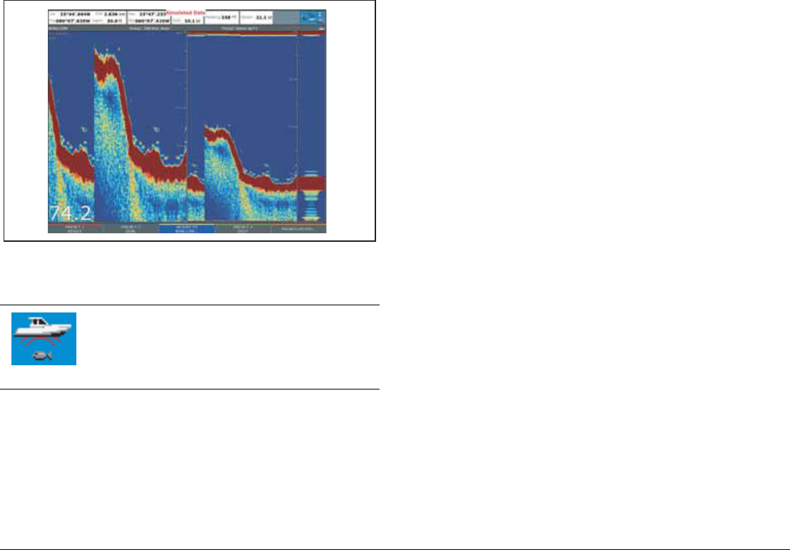
G-Series Reference Manual 92
8.1 The fishfinder display
The fishfinder displays a scrolling image of the seabed, updating
from the right as your vessel makes progress.
The fishfinder status icon is located in the top-right section of the
monitor:
8.2 Background information
The fishfinder requires a Digital Sounder Module (DSM) to process
acoustic signals and build up a detailed picture of the seabed.
A transducer on the bottom of the boat sends pulses of sound
waves into the water and measures the time it takes for the sound
wave to travel to the bottom and back. The returning echoes are
affected by bottom structure and by any other objects in their path,
for example reefs, wrecks, shoals or fish.
The strength of the echoes is indicated on the display by different
colors. You can use this information to determine the shape and
make-up of the seabed, or the size of shoals, or of other objects.
8.3 Operating the fishfinder
The fishfinder provides you with four preset configurations, avail-
able on the default toolbar. These are tailored to provide optimal
operation in different circumstances - you should be able to find a
preset that gives you excellent results in any situation.
The presets are labelled single, dual, shallow and deep. When you
make a fishfinder window active, the title bar shows you which pre-
set is selected, along with its settings.
Each preset has been configured to provide the best operating
parameters for the fishfinder. However, it is possible to adjust the
presets if necessary.
To select a preset mode
1. Press the appropriate softkey.
Icon animated - connection to a DSM has been
successful.
Icon static - the DSM is connected but not transmitting.
Icon greyed-out - no DSM is connected.
D10560-1
D9534_1
(animated icon)
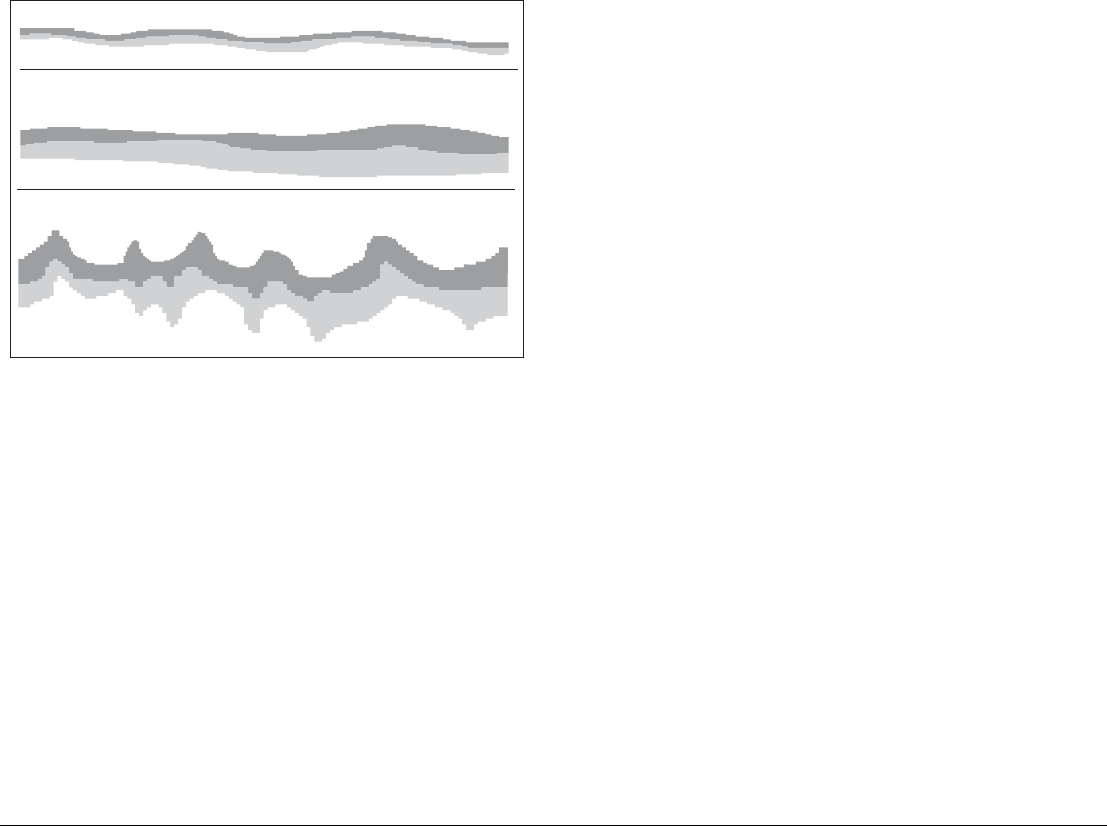
93 Chapter 8: The Fishfinder
8.4 Explaining the readout
The dark layers indicate a good echo; the lighter areas weaker ech-
oes. This could mean that the upper layer is soft and therefore
allowing sound waves to pass to the more solid layer below.
It is also possible that the sound waves are making two complete
trips – hitting the bottom, bouncing off the boat, then reflecting off
the bottom again. This can happen if the water is shallow, the bot-
tom is hard, or gain is set too high.
8.5 Factors influencing the readout
The quality and accuracy of the display can be influenced by a
number of factors including boat speed, depth, object size, back-
ground noise and transducer frequency.
Boat speed
The fishfinder’s reading of the bottom changes as your speed
changes. Slower speeds return flatter, more horizontal marks; as
your speed increases, the image will tend to thicken and arch, until
at high speeds the bottom resembles a double line on the fishfinder
display.
Depth
As sea depth increases, signal strength decreases, resulting in a
lighter on-screen image of the bottom.
Object size
The larger an object is, the stronger its return on the fishfinder dis-
play will be.
However, the strength of return from fish depends upon the spe-
cies’ swim bladder, rather than the body size.
Background noise
The fishfinder readout can be affected by weak echoes from float-
ing or submerged debris, air bubbles, or by your boat’s movements.
This background noise is also known as clutter, and the G-Series
system automatically adjusts sensitivity to it based on sea depth
and water conditions. You can, however, set the sensitivity manu-
ally by using the gain modes (gain, color gain and TVG).
Transducer frequency
•Lower frequencies scan a wide area and penetrate water well.
Use these settings if you want a large coverage beneath your
boat or if you are in deep water.
D6855-2
A hard bottom (sand) produces a thin line
A soft bottom (mud or seaweed cover) produces a wide line.
The dark layer indicates a strong signal.
A rocky or uneven bottom or a wreck produces an irregular
image with peaks and troughs

G-Series Reference Manual 94
•Higher frequencies (200 Khz) scan a narrow area but produce
more detail, especially at high boat speed. They are most useful
in shallower waters (up to 1000 feet).
Various frequencies may be available on your system, depending
on the transducers fitted to your vessel.
Viewing single or dual frequencies
If the preset you are using includes two frequencies, you can use
one fishfinder window to view both frequencies or just one. You can
then send the second frequency to a fishfinder window on a second
monitor, enabling you to view both frequencies at full screen.
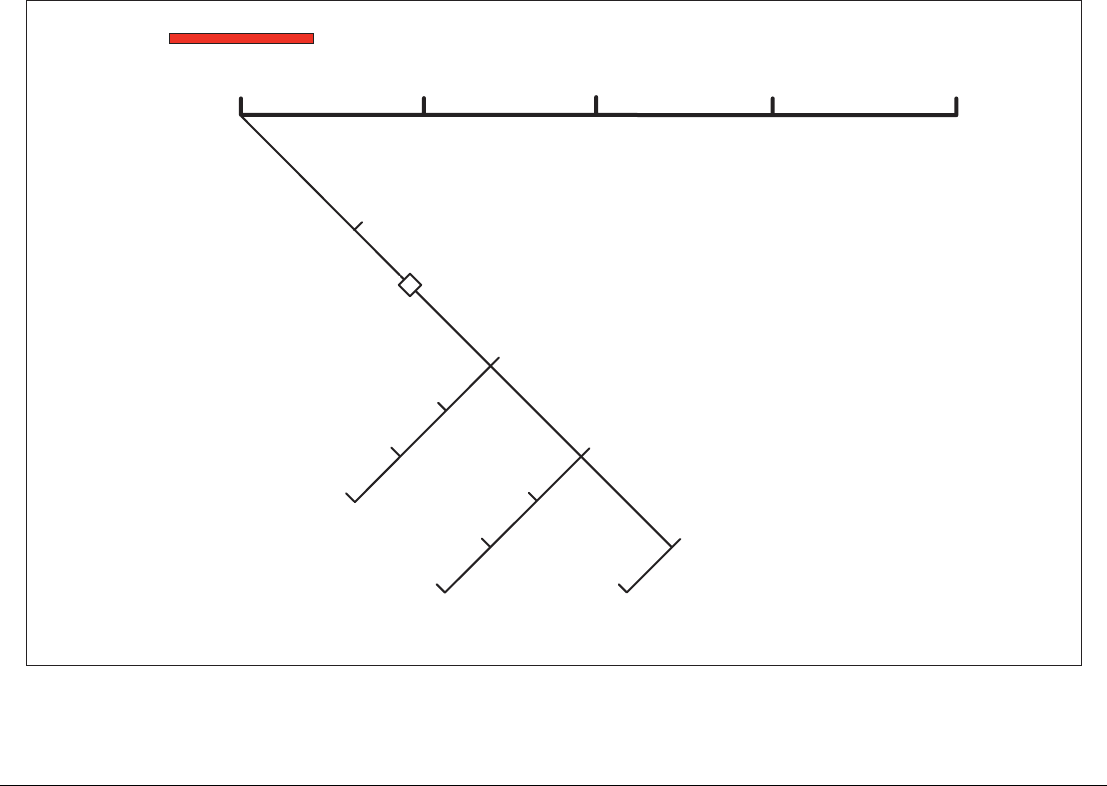
95 Chapter 8: The Fishfinder
8.6 Display mode settings
When a fishfinder preset is selected, its softkey label changes to ADJUST. Pressing this key allows you to configure the display mode
settings to suit your requirements. (Changes to the display mode are saved with the preset at power-off.)
Adjust F1 / F2
Select option
Zoom full/split
Full/split
1/2/3
Range (rotary)
Bottom shift (rotary)
Zoom factor x2/3/4, custom (R)
Zoom position auto/manual
Zoom
Bottom lock
A-Scope
ADJUST P1
SINGLE
PRESET 2
DUAL
PRESET 3
SHALLOW
PRESET 4
DEEP
PRESENTATION
D10561-1
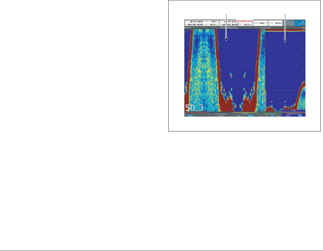
G-Series Reference Manual 96
For each preset (and for each frequency within the preset), you can
change the following display mode settings:
• Zoom
• Bottom Lock
• A-Scope
To change the settings for a preset
1. Press the ADJUST <preset name> softkey.
2. Select F1 or F2.
3. Select the mode you want to adjust.
4. Make changes using the trackpad or rotary controller.
5. Press OK when complete.
Zoom
If necessary you can zoom in on the bottom to display more detail.
This zoom option lets you:
• Replace the standard fishfinder image with the zoomed image,
or display the zoomed image alongside the standard fishfinder
image.
• Set the zoom factor to a pre-defined level, or adjust it manually.
• Reposition the zoomed portion of the image to a different point
in the display.
When the range increases, the area shown in the zoom window
also increases.
Full or split screen
You can either replace the standard fishfinder image with the
zoomed image or split the screen and display the zoomed image
alongside the standard fishfinder image (ZOOM SPLIT). The
zoomed section is indicated on the standard fishfinder screen by a
zoom box (see illustration below).
To select split-screen or full-screen
1. Select FULL or SPLIT with the ZOOM softkey.
When the zoom function is active (ZOOM FULL or ZOOM SPLIT),
you can either select a predefined zoom factor or adjust it manually.
To select the zoom factor
1. Press the ZOOM softkey.
2. On the ZOOM FACTOR key, toggle between pre-defined
settings or select xR to set a factor manually. For manual
settings, adjust the zoom factor with the rotary controller.
3. Press OK to accept your setting.
D10562-1
Zoom pane Standard pane
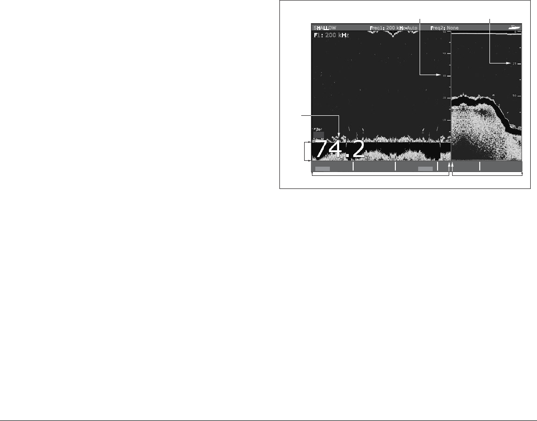
97 Chapter 8: The Fishfinder
Adjusting the position of the zoomed area
When the zoom function is selected, the system automatically
selects the zoom position so that the bottom details are always in
the lower half of the display. If required you can reposition the por-
tion of the image to be zoomed so that an alternative area is
displayed.
To set the zoom position
1. Press the ZOOM softkey.
2. Select MAN with the ZOOM POSITION softkey.
3. Reposition the zoomed image using the rotary controller.
4. Press OK.
Bottom lock and bottom shift
The Bottom Lock function applies a filter to flatten the image of the
seabed and make any objects on or just above it easier to discern.
This feature is particularly useful for finding fish that feed close to
the bottom.
Bottom Lock is selected for individual fishfinder windows and can
replace or appear alongside the standard fishfinder image.
Adjusting the range of the bottom lock image allows you to view
more bottom details. You can also reposition the image on screen
to anywhere between the bottom of the window (0%) and the mid-
dle of the window (50%) by using the Bottom Shift control.
To adjust bottom lock
1. Toggle to FULL or SPLIT.
2. Use the appropriate softkeys and rotary controller to set the
range and bottom-shift values.
Using A-Scope to view a live image
The standard fishfinder display shows a historical record of fish-
finder echoes. If required, you can display a live image of the
bottom structure and the fish directly below the transducer by using
the A-Scope feature. The width of the bottom area covered by the
A-Scope is indicated by the number at the bottom of the window.
The A-SCOPE softkey
When A-Scope is on you can select one of three display modes:
BL
B-LOCK RANGE
50ft
BOTTOM SHIFT
14%
BOTTOM LOCK
FULL SPLIT
F1: 200 kHz
SHALLOW Freq1: 200 kHz-Auto Freq2: None
SELECT OPTION
BOTTOM LOCK
ADJUST
FREQ1 FREQ2
Depth from the surface
Bottom lock range
(distance from bottom)
Bottom
shift
Depth
reading
Bottom lock image Standard fishfinder image
D10412-1
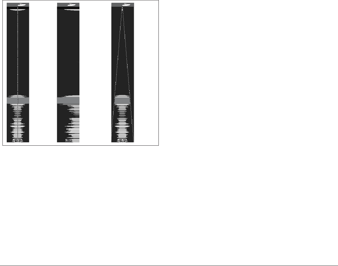
G-Series Reference Manual 98
To display the A-Scope image
1. Select A-Scope on the SELECT OPTION softkey.
2. Choose your mode on the A-SCOPE MODE softkey.
D6674-3
MODE 1
The A-scope
image is centred
in the window.
MODE 2
The left-hand side
of the Mode 1
image is expanded
to give a more
detailed view.
MODE 3
The A-scope
image angles
outward as
signal width
increases with
depth.
99 Chapter 8: The Fishfinder
Changing the range
You can change the range for each displayed frequency from the Range Adjust toolbar, which gives you control over the range and range-
shift settings.
The DSM automatically adjusts the display to show the shallowest
required range. Alternatively, you can range in or out on the image,
up to the maximum depth displayed on the scrolling bottom and
A-Scope images. Changes to the range affect all fishfinder
windows.
To open the Range Adjust toolbar
1. Press the RANGE button on the G-Series keyboard.
To select manual or auto range mode
1. Open the Range Adjust toolbar.
2. Toggle to AUTO or MAN on the RANGE softkey.
3. Press OK.
Range shift
The DSM automatically adjusts the display to keep the bottom in
the lower half of the display window. Alternatively, you can shift the
image within the current range. Changes to the range shift are
reflected in all Fishfinder windows.
To shift the range image
1. Open the Range Adjust toolbar.
2. Press the RANGE SHIFT softkey.
3. Select your desired setting using the rotary controller or
trackpad.
4. Press OK.
Range auto/manual
Range shift
Select frequency high/low
High frequency shift
RANGE
OUT
IN
D10563-1

G-Series Reference Manual 100
To return to the standard fishfinder image
1. Toggle to AUTO on the RANGE softkey.
2. Press OK.
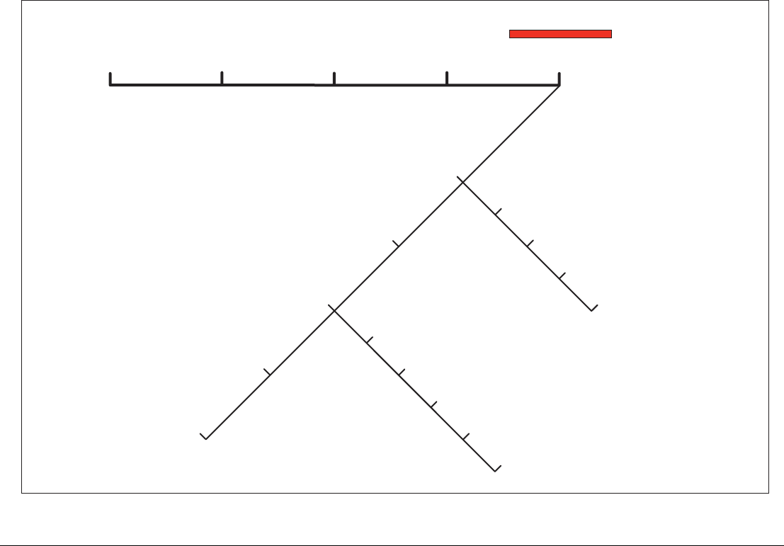
101 Chapter 8: The Fishfinder
8.7 Presentation toolbar
The PRESENTATION softkey gives you access to VRM features (for measuring depth and distance), frequency view selection and a scroll
control. These settings affect the monitor you are working on.
ADJUST P1
SINGLE
PRESET 2
DUAL
PRESET 3
SHALLOW
PRESET 4
DEEP
Gain
Power Auto/Man
PRESENTATION
VRM
View F1/F2/Both
Scroll pause/resume
Scroll pause/resume
Color gain auto/manual
Gain mode auto/manual (low, medium, high)
TVG auto/manual
Color threshold
VRM range
VRM on/off
VRM depth
View F1/F2/Both
D10564-1

G-Series Reference Manual 102
8.8 Adjusting gain and power
Changing the preset gain settings alters the way the fishfinder pro-
cesses background noise (also called clutter), and can improve the
readout on the monitor. You can adjust:
• Gain mode (choose from three auto-settings or manual control)
• Color gain
• TVG
• Color threshold
If you change settings for any of these modes (except auto gain),
the fishfinder applies them to all transducer frequencies.
For optimum performance, use the auto settings.
Auto gain settings
The gain, or sensitivity, of the display adjusts background noise by
varying the echo strength for display. The value of the GAIN control
determines the strength above which echoes are displayed. There
are three AUTO GAIN modes, which are saved with the preset if
power is removed from the system:
•Low (the default setting) is ideal for viewing fishfinder images
with a minimum of background noise while you cruise to your
fishing spot. Only the strongest echoes are displayed.
•Medium is a slightly higher gain setting that displays more
detail.
•High provides the most detail, but also displays the most back-
ground noise and surface clutter.
To select an auto gain setting
1. Press the GAIN MODE softkey.
2. Select the auto setting from the pop-up list.
3. Press OK.
Manually-set gain levels
If necessary you can set gain levels manually. Manually-set gain
levels are applied to the active window and any other fishfinder win-
dows displaying that frequency.
To set the gain level manually
1. Press the GAIN MODE softkey.
2. Toggle the setting to MAN.
3. Use the slider to set your required gain value.
4. Press OK.
Gain should be set high enough to see fish and bottom detail but
without too much background noise. Generally, high gain is better
in deep or clear water; low gain is better for shallow or murky water.
The default setting for manual gain is 75%.
Color Gain
This sets the lower limit for the strongest echo color. All echoes with
a signal strength above this value are displayed in the strongest
color. Those with a weaker value are divided equally between the
remaining colors. Setting a low value produces a wide band for the
weakest color, but a small signal band for the other colors; setting a
high value gives a wide band for the strongest color, but a small
signal band for the other colors.
TVG (Time Varied Gain)
The TVG (Time Variable Gain) reduces clutter by varying the gain
throughout the water column. This function is useful for reducing
the appearance of ‘noise’.
Increasing the TVG value increases the maximum depth to which
TVG is applied; decreasing it reduces the maximum depth. A low
TVG value has little effect on gain in shallow water; a high value
decreases the gain in shallow water so that only the strongest ech-
oes are displayed.
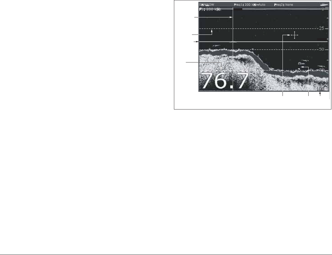
103 Chapter 8: The Fishfinder
Power setting
The power setting controls the power level of the transducer.
Auto
This is the default setting. When it is selected the DSM automati-
cally determines the required power setting based on the current
depth, speed, and (bottom) signal strength.
Manual
If you wish to manually adjust the power to suit current conditions,
you can adjust the power level between 0% and 100%, in 10%
increments. Lower power levels are normally used in depth ranges
less than 8 ft. (2.4 m) and higher power levels are typically selected
for depths greater than 12 ft. (3.7 m).
To change the power setting
1. Press the ADJUST softkey for the preset you are using.
2. Press to the manual or auto setting on the POWER softkey.
3. In manual mode, use the rotary controller or trackpad to choose
the power setting you want to use.
4. Press OK.
8.9 Measuring depth and distance
The fishfinder display gives you various methods of measuring
depth and distance:
•Depth reading - your current depth. The size and position of
this readout can be changed in the Fishfinder display Setup
menu (see page 107).
•Depth lines - horizontal dashed lines drawn at regular intervals
to indicate the depth from the surface. These are switched on/
off in the Fishfinder Display Setup menu (see page 107).
•Depth Target ID - depths noted against recognized targets.
The sensitivity of these IDs is directly linked to the Fish Alarm
sensitivity; the greater the fish alarm sensitivity, the greater the
number of labelled returns. These targets are switched on/off in
the Fishfinder Display Setup menu (see page 107).
•Cursor depth - the depth and the distance from your boat
marked by the cursor, is indicated in the data bar at the top of
the screen. This performs in a similar way to a VRM, but without
lines.
•VRMs - to indicate the distance behind your boat and the depth
below of selected objects.
74
70
67
74
49
46
44
1768ft
42.2ft
63
74 75
VRM 1
ON OFF
RANGE
0.787nm
DEPTH
44.7ft
F1: 200 kHz
SHALLOW Freq1: 200 kHz-Auto Freq2: None
VRM marker
indicating
depth of target
Depth
reading
Depth line
Depth
markers
Depth
target ID
Cursor
(depth indicated
in data bar)
VRM marker
indicating
distance
behind boat
D10411-1
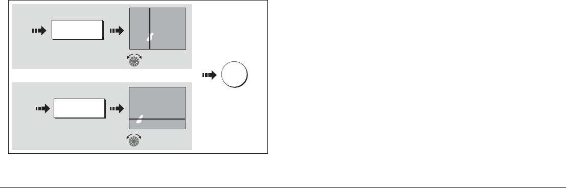
G-Series Reference Manual 104
Note: When multiple fishfinder windows are open, we recommend
you have the depth reading displayed in at least one
window.
Measuring depth and distance with VRM
You can use a Variable Range Marker (VRM) to determine the
depth and distance-behind-boat of an object. These markers con-
sist of a horizontal (depth) line and a vertical (distance-behind-boat)
line; each of which are marked with the appropriate measurement
and are controlled individually.
Note: VRMs set up in Fishfinder are unrelated to those set up in
Radar.
To make a measurement using VRM
1. Press the PRESENTATION softkey.
2. Press the VRM softkey.
3. Toggle to ON.
4. Pause the display to make it easier to position the VRM over the
object.
5. Take your measurements:
To return the marker to its previous position, press CANCEL.
Adjusting the scroll mode and speed
You can adjust the speed at which the display scrolls, but the same
section of the bottom is displayed regardless of scrolling speed. A
faster speed displays more detail. This is useful when you are look-
ing for fish. If you select a slower speed the information remains on
the display for longer.
The following options are available:
•Manual - This allows you to set the scroll speed as a percent-
age of the maximum scroll rate for that depth. The lower the
percentage, the slower the image will scroll. The default is man-
ual adjustment with a full speed scroll (100%).
To select the scroll mode and speed
1. Open the Fishfinder Setup Menu.
2. Set your preferred values in the Manual Scroll Speed setting.
Pausing scroll
You can pause the display to see a ‘snapshot’ of the image. When a
display is paused, scrolling stops but the depth indication continues
to be updated.Scroll pause/resume affects the frequency showing
on your display (both frequencies if two are selected) while other
displays continue to scroll.
This allows you to inspect a paused image, place waypoints or
VRMs, while the other frequency continues to scroll and detect fish.
To pause or resume scrolling
1. Press the PRESENTATION softkey.
2. Toggle settings on the SCROLL key.
3. Press OK.
Move range
marker over target
RANGE
49ft
Measuring distance
Measuring depth
and/or
e.g.
e.g.
Press to highlight
DEPTH
10ft
1.56nm
Move depth
marker over target
12ft
D8455_1
OK
To save
position

105 Chapter 8: The Fishfinder
Viewing frequencies within a preset
If the preset you are using has two frequencies, you can view either
one or both of those frequencies in separate windows.
To set frequency views
1. Press the PRESENTATION softkey.
2. Toggle to F1,F2 or BOTH on the VIEW softkey.
3. Press OK.
Placing waypoints
You can pause the scrolling image to place a waypoint at a position
or target that you want to return to at a later date. When a waypoint
is placed, its details are added to the Waypoint List and a vertical
line labelled WPT is placed on screen. You can edit waypoints and
navigate to them in an active fishfinder window.
8.10 Fishfinder alarms
In addition to the system alarms (see page 194), the following
alarms can be set when you are connected to a DSM or when the
simulator is on:
•Fish Alarms - sound when a target meets the specified sensi-
tivity level and, is within the depth limits (if enabled). The
greater the fish alarm sensitivity, the greater the number of tar-
get image depths displayed.
•Shallow/Deep Alarms - sound when the DSM detects that the
depth is less than the shallow limit, or greater than the deep
limit.
You can switch the alarms on, set the limits and specify the fish
alarm sensitivity.
8.11 Editing presets
You can select frequencies for each preset from the Setup Fre-
quency Preset screen. All available frequencies are detected by the
system and made available on this menu. You can:
• Specify one or two frequencies for each of the four presets.
• Edit preset names (EDIT NAME softkey).
• Reset all presets to factory defaults (RESET ALL softkey).
• Reset a selected preset to factory defaults (RESET <PRESET>
softkey).
The fishfinder can can handle only one set of frequency presets
across Nav Stations. It is not possible to set one Nav Station up
with a different set of fishfinder frequencies to another.
To open the Setup Frequency Preset screen
1. With a fishfinder window active, press the MENU button .
2. Select Configure Frequency Presets.
Manual frequency selection
If you select a frequency manually, the fishfinder operates at that
fixed frequency.
To set frequencies manually
1. Open the Configure Frequency Presets screen.
2. Select the frequency use wish to use from the list available.
Automatic frequency selection
The behaviour of automatic frequency selection varies according to
the configuration of your system and whether you are using a
DSM300 or DSM400. The table below summarises this behaviour.

G-Series Reference Manual 106
Frequency 1 Behaviour Frequency 2 Behaviour
DSM400 AUTO Automatically
adjusts to suit
depth.
NONE/MAN Manual setting
is fixed.
MANUAL Fixed at
selection.
NONE/MAN Manual setting
is fixed.
AUTO Automatically
selects highest
frequency and
widest beam.
AUTO Automatically
adjusts to suit
depth.
DSM300 AUTO Changes with
depth; alter-
nate pings of
50 Khz and
200 Khz.
MANUAL Fixed at
selection.
AUTO Changes with
depth; alter-
nates between
50 Khz and
200 Khz.
NONE -
AUTO Frequency set
to 200 Khz.
AUTO Frequency set
to 50 Khz.

107 Chapter 8: The Fishfinder
8.12 Fishfinder configuration
This section describes the settings you can change using the fishfinder setup menu. The setup menu contains settings that are likely to be
changed infrequently.
For information on how to use setup menus, see Setup menus on page 23.
To open the fishfinder setup menu
1. Make a fishfinder window active.
2. Press the MENU button.
3. Select Fishfinder Setup.
Fishfi nder Setup > Confi gure Preset Frequencies
Depth digit size
Depth Digit Position
Target Depth ID
Depth Lines
White Line
Bottom Fill
Color Palette
Manual Scroll Speed
Transducer Settings > Select Transducer
Select Speed Transducer
Frequency Calibration
Depth Offset (Waterline)
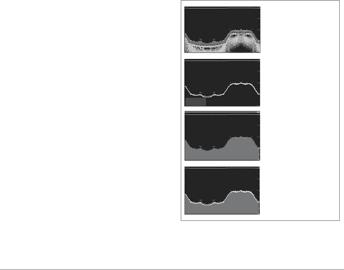
G-Series Reference Manual 108
DSM and transducer setup
Nearby vessels equipped with a fishfinder, or certain physical con-
ditions (like hard seabeds), can affect the DSM. Its setup menus
enable you to change settings to allow for this.
The system automatically adjusts the following settings to optimize
the fishfinder image.
• Operating frequency.
• Gain modes (Gain, Color Gain, TVG).
• Power setting.
Note: The setup options available depend upon the DSM fitted
to your vessel.
Fishfinder settings should not ordinarily require adjustment.
Configure preset frequencies
Change the settings for one or more of the fishfinder presets. The
settings available depend upon the transducer fitted.
Target depth ID
Depth readings for identified targets.
Depth lines
Horizontal lines indicating depth.
White line and bottom fill
Distinguish between echoes from fish near the bottom and from the
bottom itself. (See illustration.)
Color Palette
Choose the color palette to suit your conditions or personal
preference.
75.9
ft
100
75
200 kHz: Auto Gain: Auto High
75.9
ft 100
75
200 kHz: Auto Gain: Auto High
75.9ft
200 kHz: Auto Gain: Auto High
75.9
ft
75
200 kHz: Auto Gain: Auto High
D6833-3
Standard fishfinder image
The standard fishfinder image displays the
bottom as a combination of features (mud,
sand, fish targets etc) with various sonar
signal strengths.
White line
When this feature is applied, a white lIne
is drawn along the bottom (as defined by
the digital depth value) and the detail
below the bottom removed.
Fish near the bottom can now be seen
more easily.
Bottom fill
When this feature is applied, the detail
below the bottom is removed and
replaced by a single contrasting color.
The bottom is now clearly defined and the
fish near the bottom can be seen more
easily.
White line and bottom fill
When both White Line and Bottom Fill
are applied, the bottom is defined by a white
line and the detail below it replaced by a
single contrasting color.
Both the bottom and fish near the bottom
are now clearly defined.

109 Chapter 8: The Fishfinder
Manual Scroll Speed
Specify the speed at which the fishfinder view updates and scrolls.
Select Transducer
When selecting a transducer, the DSM reports to the G-Series
whether it sees a 600W or 2kW transducer. This allows you to
select an appropriate transducer from the list.
Select Speed Transducer
This option is only available if the selected transducer is one that
does not include an integrated speed transducer.
Frequency Calibration
Hides the setup menu and brings up a set of soft keys to tune the
transducer frequencies.
Depth Offset (waterline)
Offset represents the depth of the transducer (relative to the
waterline)
Speed and temperature offsets
Calibrate the speed transducer and thermistor (if fitted).
DSM Reset
Restores all settings to factory default.
Trip Counter Reset
Zero the trip counter.
Interference Rejection
Removes spikes caused by interference from other fishfinder-
enabled vessels.
2nd Echo Interference Rejection
Finely adjust the ping rate according to the 2nd echo level.
Ping Rate Limit (per sec)
Provides a speed limiter. It can be useful to adjust ping rate to suit
local conditions, for example when you are over a hard seabed or
in shallow water.
Ping Enable
Normally enabled, you can disable the ping when appropriate: to
test other equipment, or if there is a diver beneath the vessel, for
example.

G-Series Reference Manual 110

9
Chapter 9: Sirius Weather (US only)
Overview
The weather application superimposes historical, live and forecast weather data onto a world map.
You can use the data to check the weather for your current position or for areas you are planning to visit.
For a basic weather glossary, see the appendix at the back of this manual. For types of warnings, watches
and advisories, refer to the NOAA website at: www.nws.noaa.gov
Chapter contents
• 9.1 Disclaimer on page 112
• 9.2 Weather application pre-requisites on page 112
• 9.3 Weather application setup on page 112
• 9.4 The weather display on page 113
• 9.5 Moving around the weather map on page 113
• 9.6 Placing waypoints on page 113
• 9.7 Weather symbols on page 113
• 9.8 Weather toolbar on page 118
• 9.9 Viewing data for a specific position on page 119
• 9.10 Animated weather graphics on page 120
• 9.11 Viewing weather reports on page 120
• 9.12 Troubleshooting on page 121