Flir BelgiumBA CCTR Low-power (unlicensed) wireless device for leisure User Manual 87070 1 GSeries Install Comm
Raymarine UK Ltd. Low-power (unlicensed) wireless device for leisure 87070 1 GSeries Install Comm
UserManual.wiki
>
Flir BelgiumBA
>
CCTR User Manual
>
Gseries Installation Part 1
Contents
1.
Gseries Reference Part 1
2.
Gseries Reference Part 2
3.
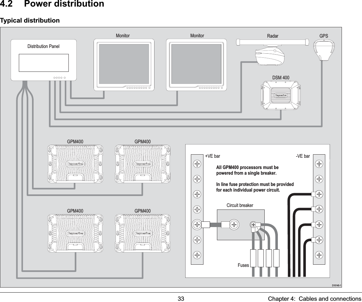
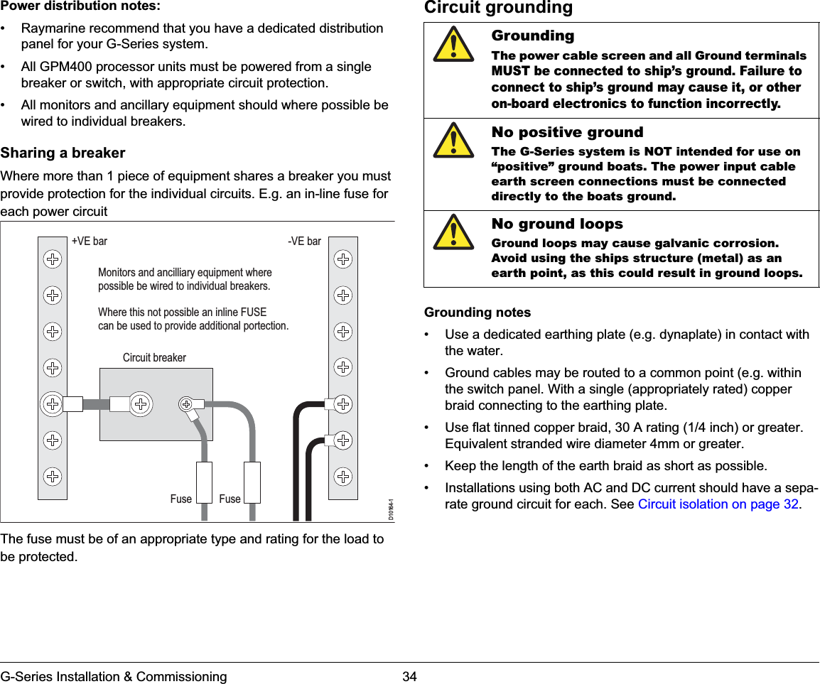
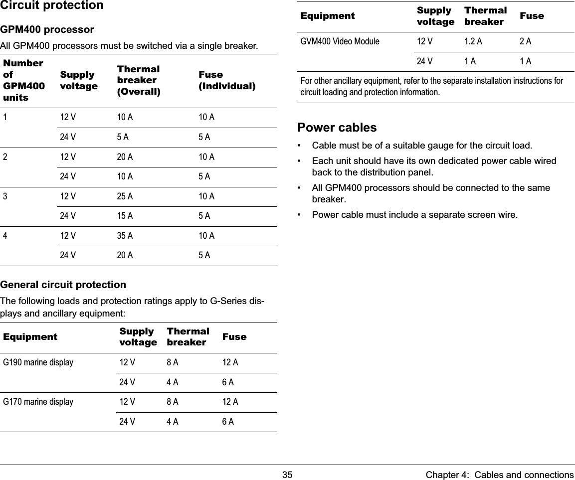
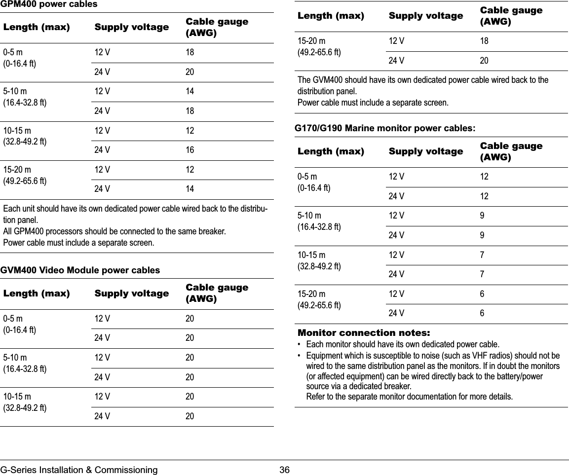
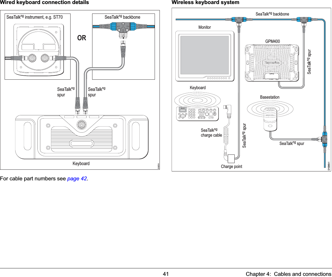
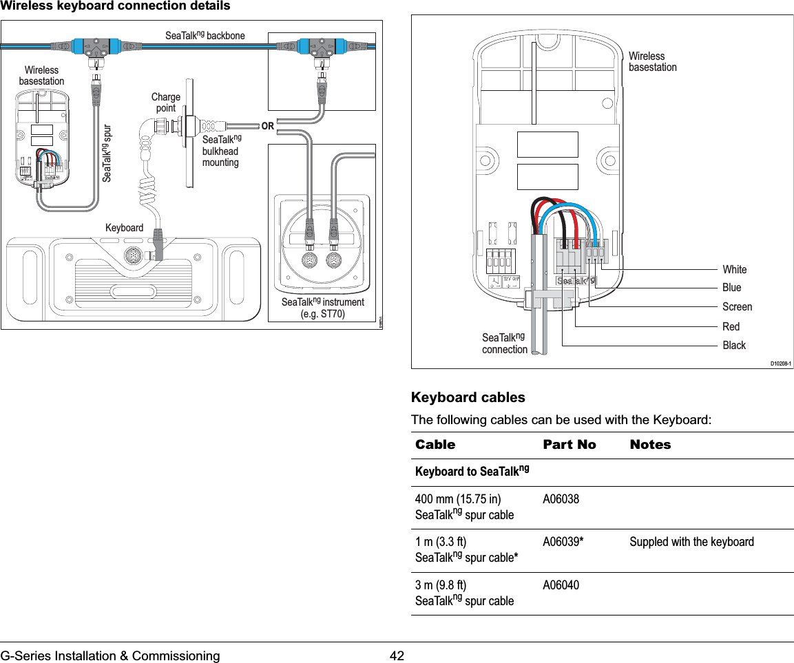
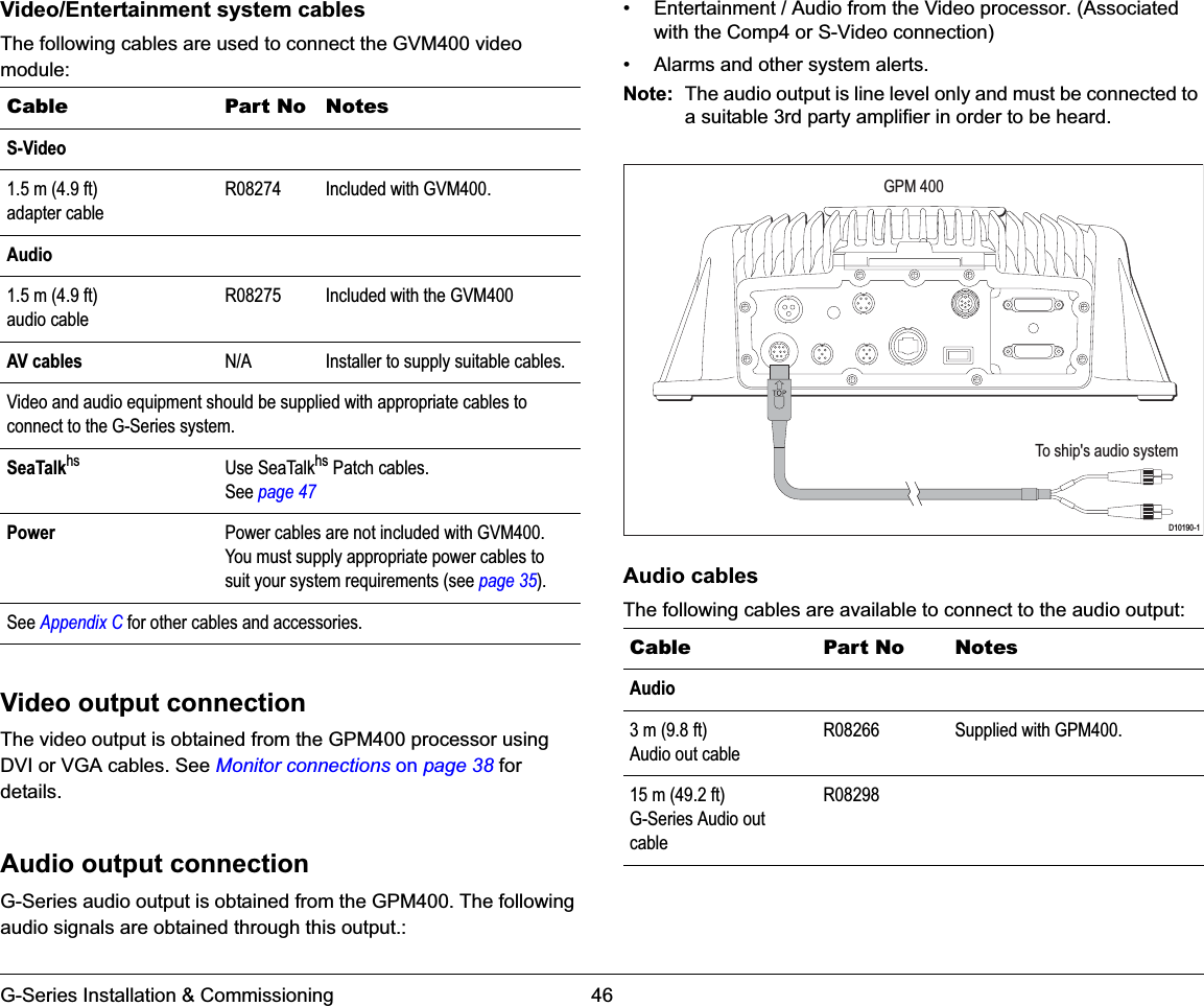
Gseries Installation Part 1
4.
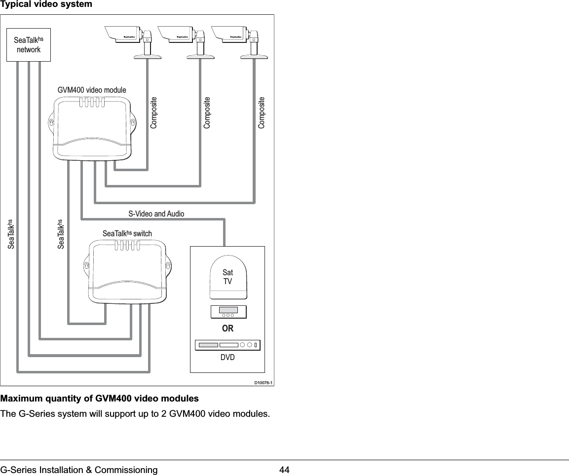
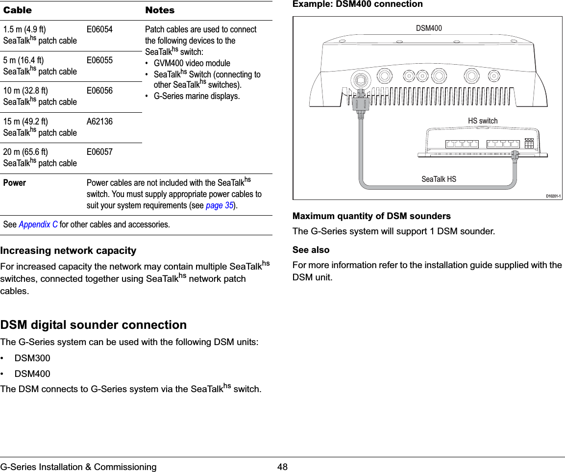
Gseries Installation Part 2
5.
Gseries Command Center
6.
Command Center Compliance
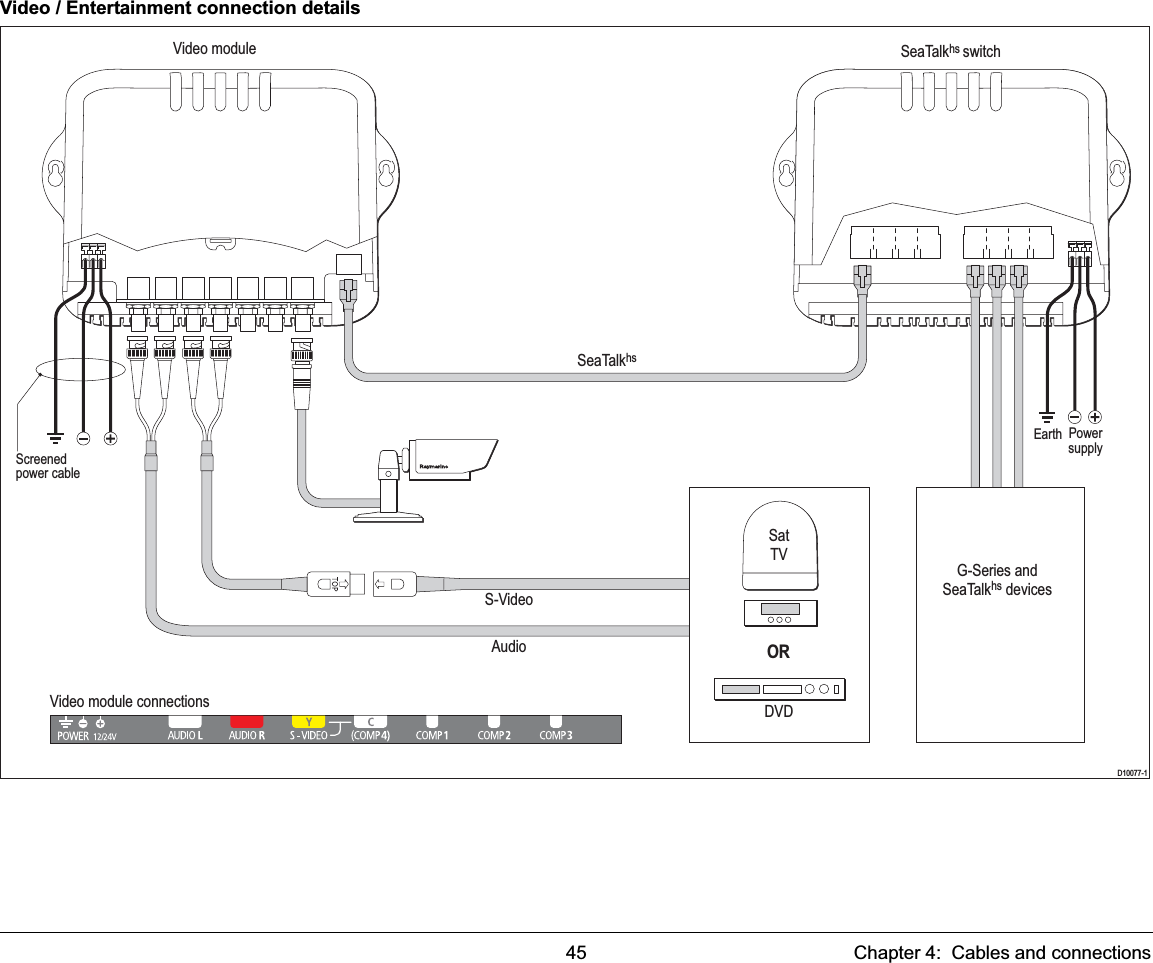
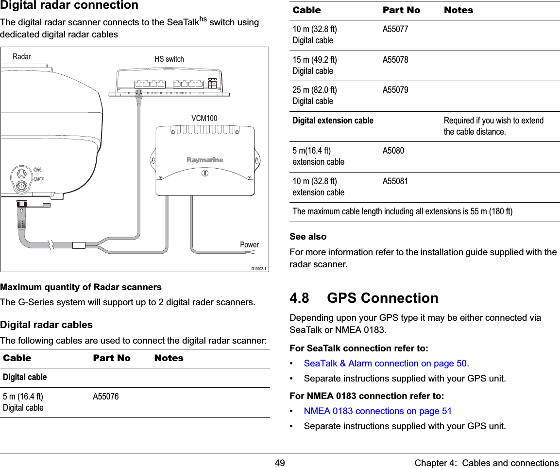
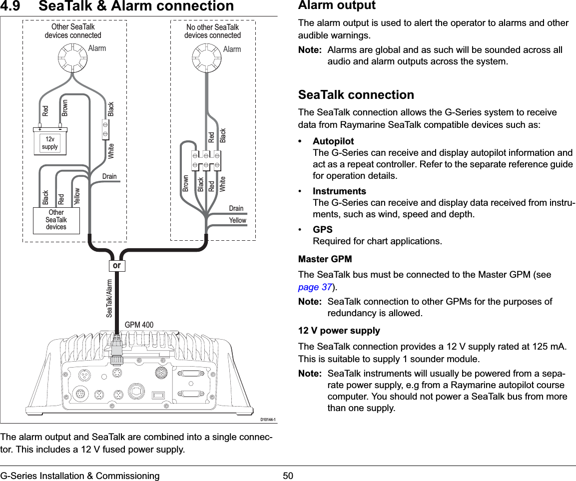
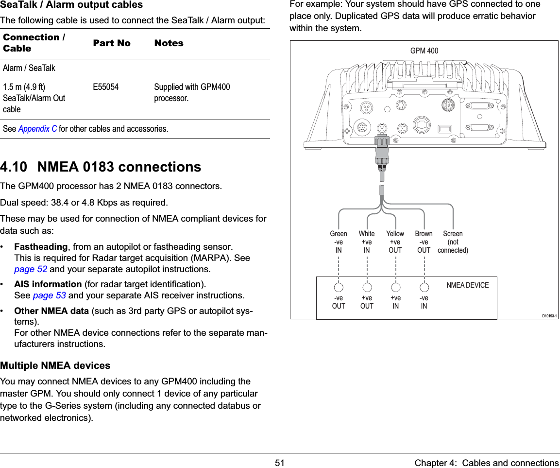
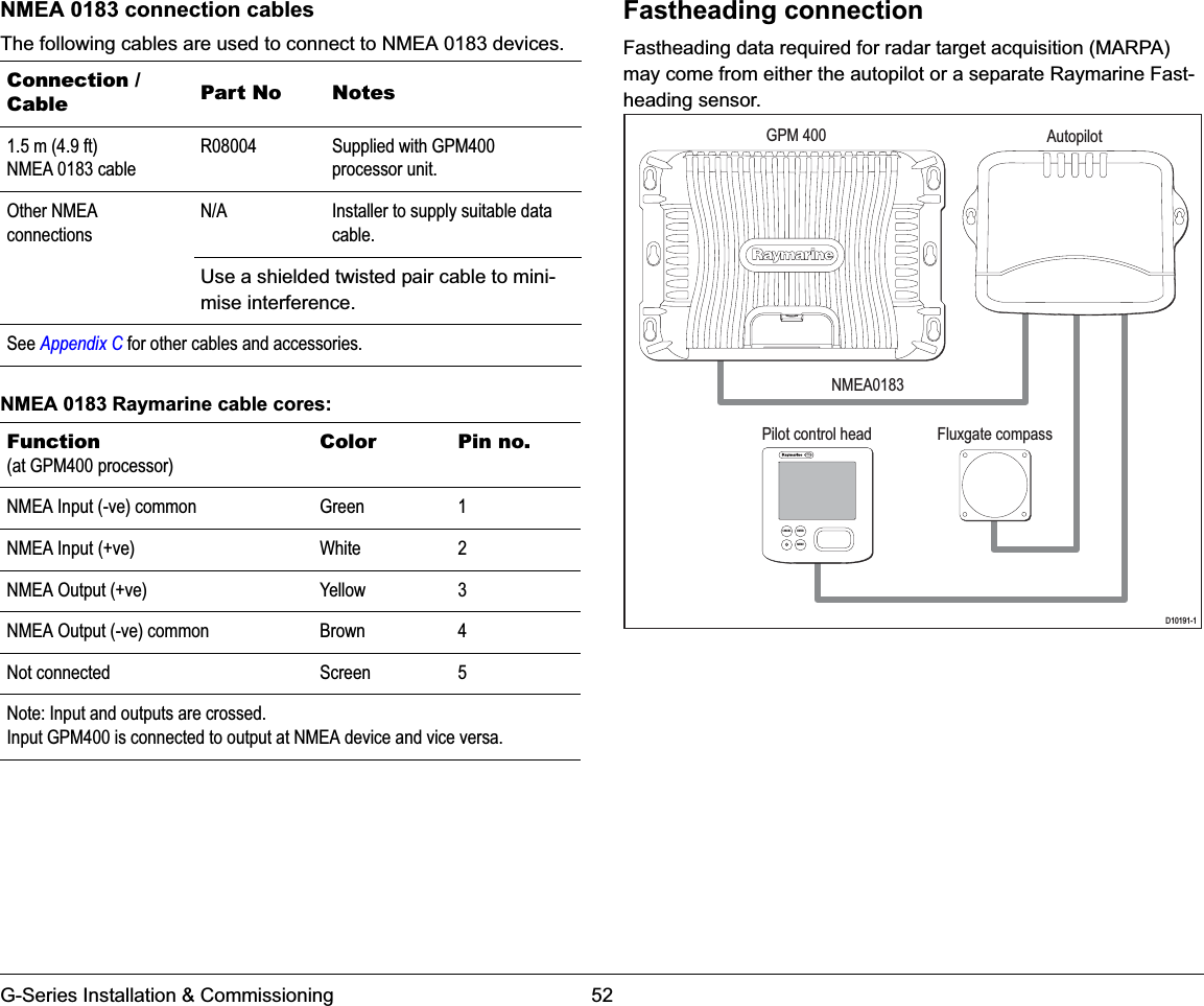
Gseries Installation Part 1
Navigation menu
Upload a User Manual
Namespaces
Wiki Guide
HTML
PDF
Info
Views
User Manual
Discussion / Help
Navigation