Flir BelgiumBA DP12KW Light Marine Navigational Radar User Manual

Raymarine UK Ltd. Light Marine Navigational Radar

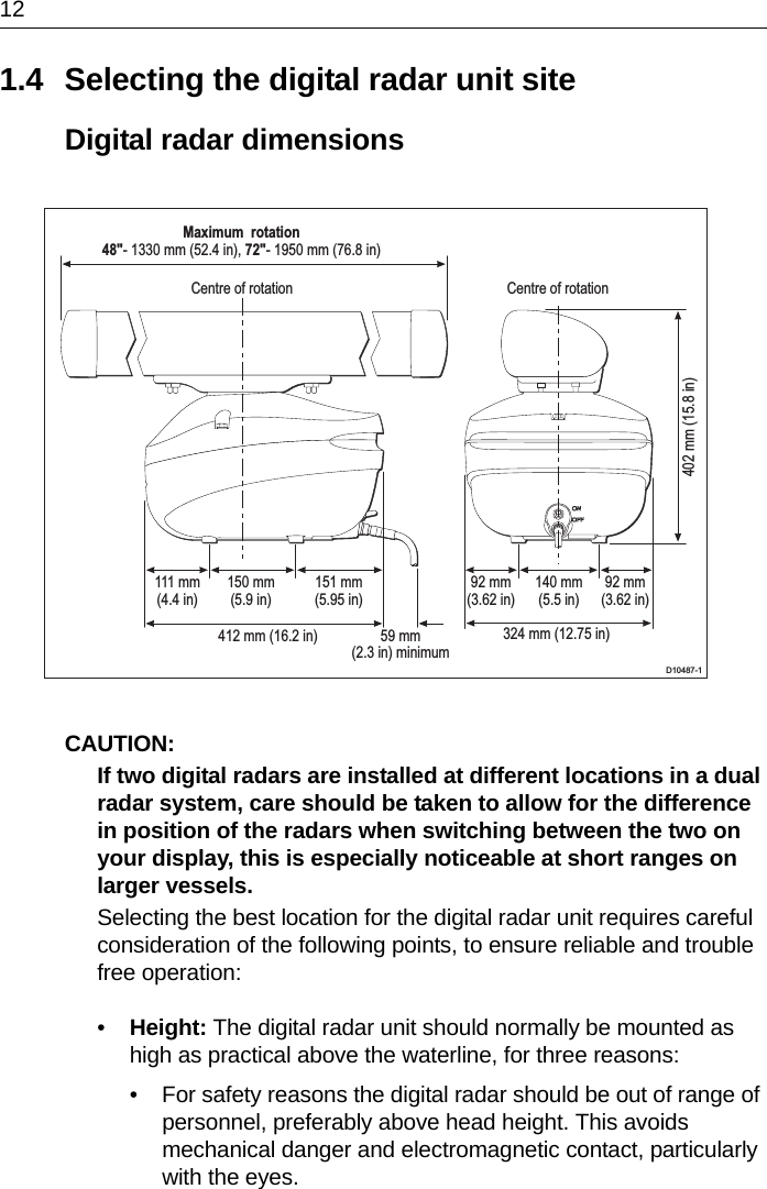
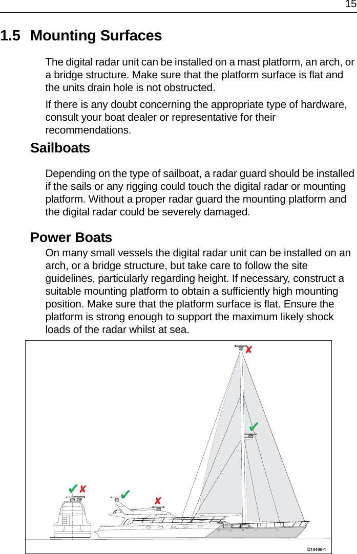
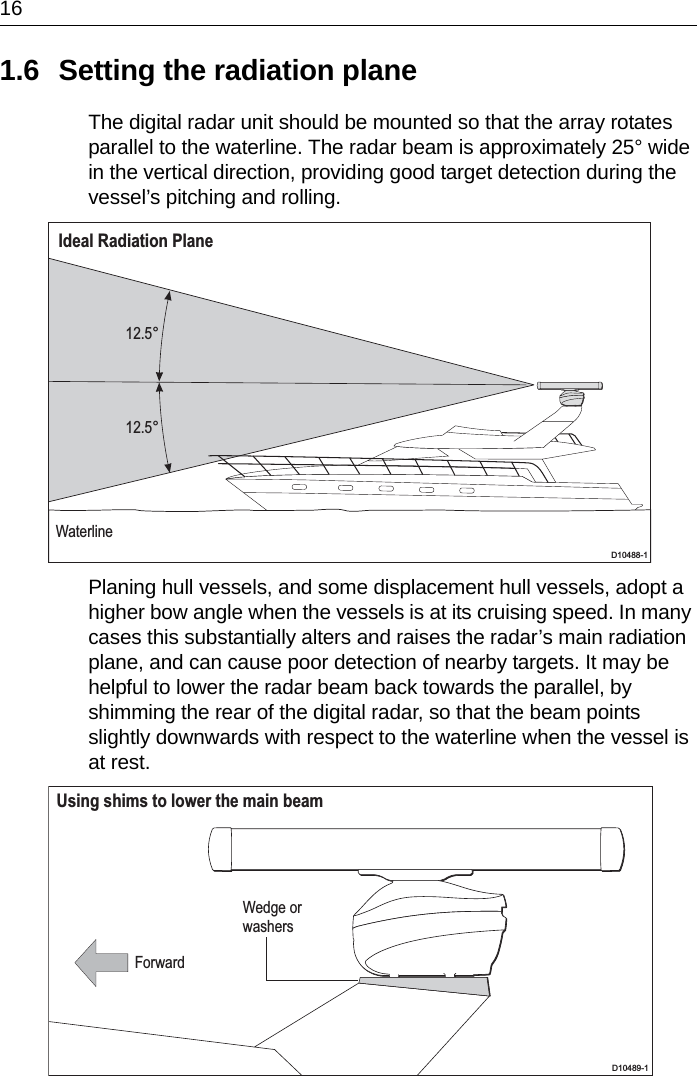
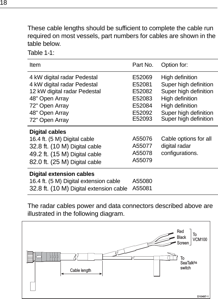
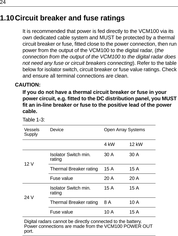
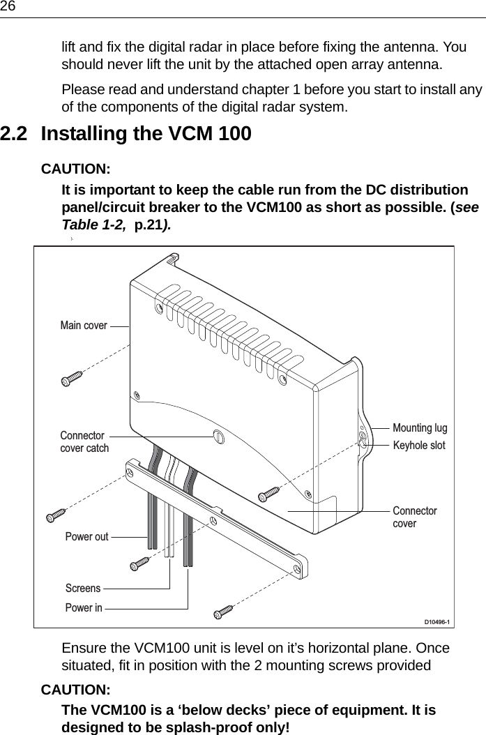
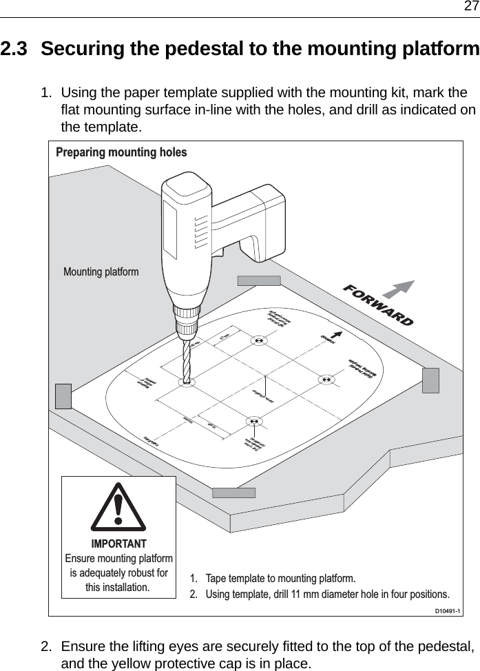
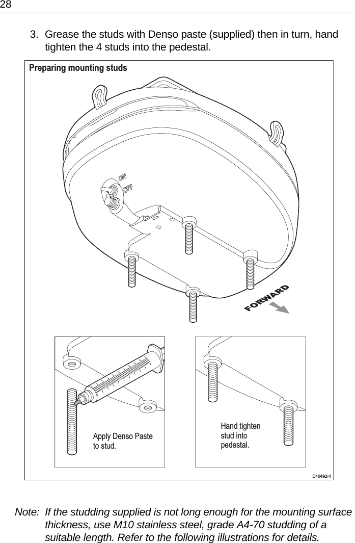
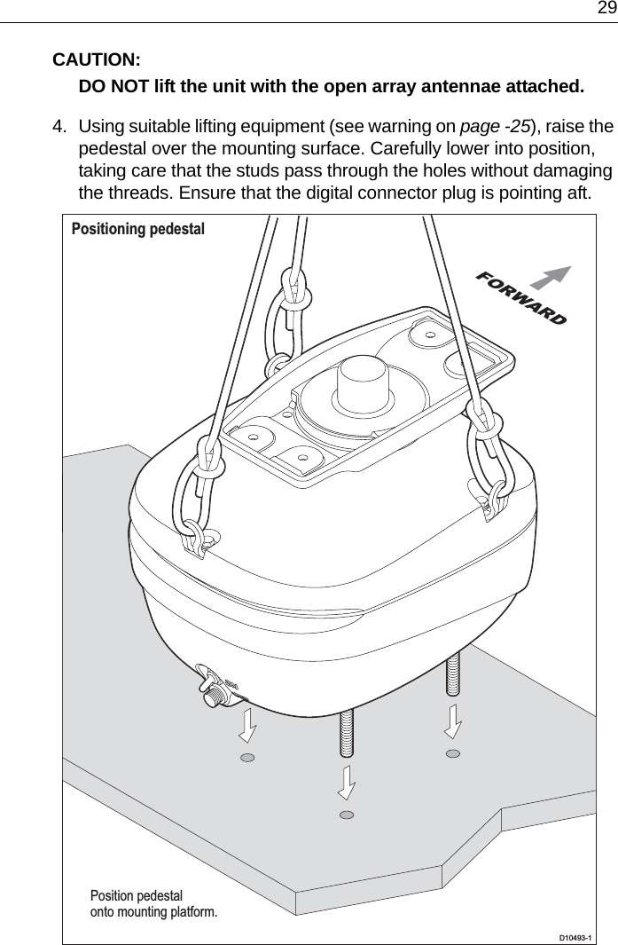
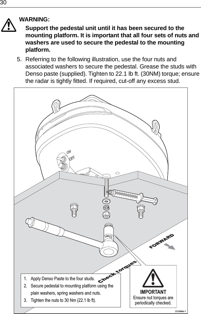
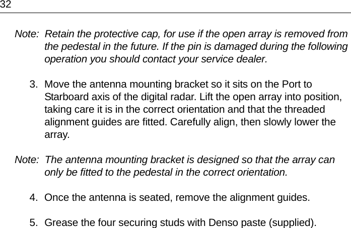
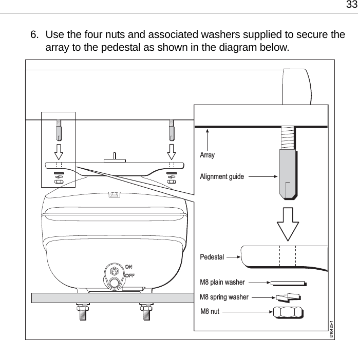
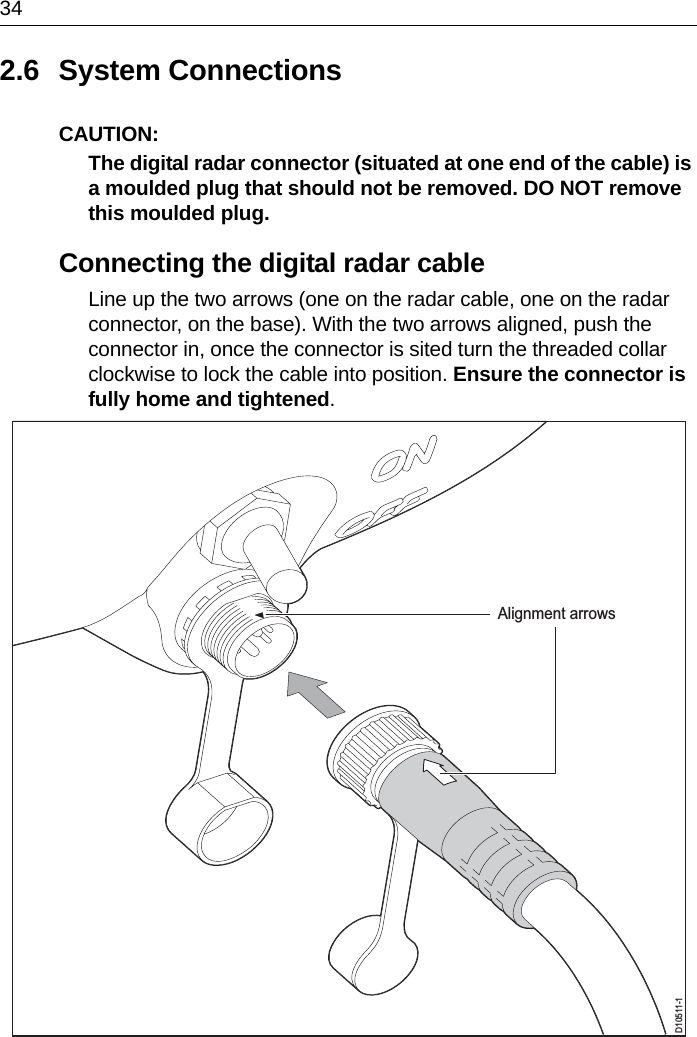
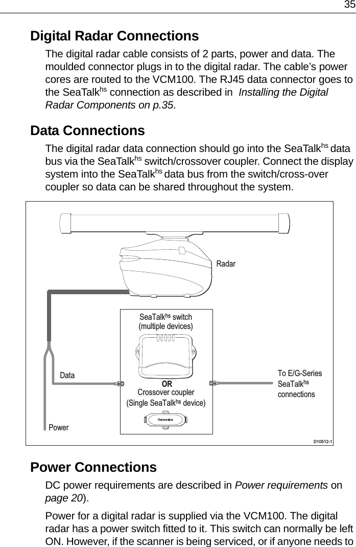
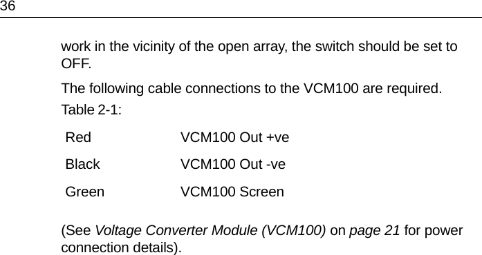
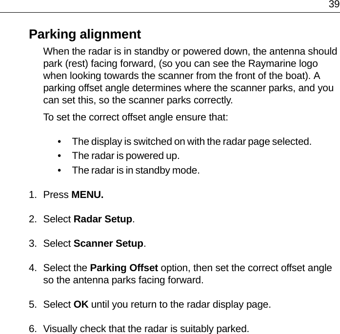
Radar installation manual

Digital Radar Installation ManualDocument number: 87087-2Date: December 2007
  iImportant Information  ...............................................................1Intended use ................................................................................. 1Raymarine Support  ...................................................................... 3System Overview .......................................................................71.1 Introduction  ................................................................................... 7System configuration .................................................................... 81.2 EMC installation guidelines ........................................................... 9Connections to other equipment ................................................. 101.3 Unpacking and inspecting the components  ................................ 11What‘s in the box?  .......................................................................11What tools do I need?  ..................................................................111.4 Selecting the digital radar unit site ............................................... 12Digital radar dimensions ............................................................. 121.5 Mounting Surfaces ...................................................................... 15Sailboats ..................................................................................... 15Power Boats  ............................................................................... 151.6 Setting the radiation plane ........................................................... 161.7 Cable requirements ..................................................................... 17Digital Radar cable  ..................................................................... 171.8 Power requirements .................................................................... 20Voltage Converter Module (VCM100) ......................................... 211.9 Grounding the digital radar system .............................................. 231.10 Circuit breaker and fuse ratings ................................................. 24Installing the Digital Radar Components .................................252.1 Digital radar ................................................................................. 252.2 Installing the VCM 100  ................................................................ 262.3 Securing the pedestal to the mounting platform .......................... 272.4 Removing the lifting eyes  ............................................................ 312.5 Fitting the open array to the pedestal  .......................................... 312.6 System Connections ................................................................... 34Connecting the digital radar cable .............................................. 34Digital Radar Connections .......................................................... 35Data Connections ....................................................................... 35Power Connections  .................................................................... 35Maintenance and Troubleshooting ..........................................373.1 EMC Conformance  ..................................................................... 373.2 System Checks ........................................................................... 373.3 Set up, alignment and timing checks ........................................... 38Switch on and initial set up .......................................................... 38Checking transmission  ............................................................... 38Bearing alignment ....................................................................... 38Display timing adjustment ........................................................... 38
iiParking alignment .......................................................................393.4 Maintenance ...............................................................................  40Routine Checks  ..........................................................................40Servicing and Safety ...................................................................413.5 Problem Solving  .........................................................................  42VCM100 status LED sequence’s ................................................43
1Important InformationDigital Radar Owners HandbookJune 2007Intended useThis product is a radar scanner intended for use within a naviga-tional radar system. The intended application is for leisure marine boats and work boats not covered by IMO/SOLAS carriage requirements.Safety NoticesWARNING:  Electrical safetyEnsure you have the power supply switched and locked off before you start installing/servicing this product.WARNING:  Navigational safetyAlthough we have designed this product to be accurate and reliable, many factors can affect its performance. Therefore, it should serve only as an aid to navigation and should never replace commonsense and navigational judgement. Always maintain a permanent watch so you can respond to situations as they develop.CAUTION:  Before installing the Digital radar system, check that individual components are the correct voltage for your boat’s supply.As correct performance is critical for safety, we STRONGLY RECOMMEND that an Authorized Raymarine Service Representative fits this product. You will only receive full warranty benefits if you can show that an Authorized Raymarine Service Representative has installed or commissioned this product.This radar equipment must be installed, commissioned and operated in accordance with the Raymarine instructions provided. Failure to do so could result in personal injury, damage to your boat and/or poor product performance. In particular1. High Voltage. The scanner unit contains high voltages. Adjust-ments require specialized service procedures and tools only avail-
2able to qualified service technicians – there are no user serviceable parts or adjustments contained in this product. The operator should never remove the digital radar units internal covers, or attempt to service the equipment.2. Radio Frequency Radiation Hazard. The radar antenna emits electromagnetic radio frequency (RF) energy which can be harmful particularly to your eyes. DO NOT look at the antenna at close range. It is important that the radar is turned off whenever personnel are required to come close to the scanner assembly or associated equipment. It is recommended that the radar scanner is mounted out of range of personnel (above head height). Distances from the face of the radar at which RF radiation levels of 100 W/m2 and 10W/m2 exist, are given below.When properly installed and operated, the use of this radar will con-form to the requirements of:• ANSI/IEEE C95.1-2005 Standard for Safety Levels with Respect to Human Exposure to Radio Frequency Electromagnetic Fields, 3 Hz to 300 GHz.• ICNIRP Guidelines 1998 - International Commission on Non-Iro-nising Radiation Protection: Guidelines for limiting exposure to time-varying electric, magnetic and electromagnetic fields (up to 300Ghz) 1998.3. Navigation Aid. This radar unit is only an aid to navigation. Its accuracy can be affected by many factors, including equipment fail-ure or defects, environmental conditions, improper handling, instal-lation or use. It is the user’s responsibility to exercise common prudence and navigational judgements. This radar unit should not be relied upon as a substitute for such prudence and judgement.Model Distance to 100 W/m2 point Distance to 10 W/m2 pointRA1048HD(4 kW) Nil Worst case1.0 MRA1072HD(4kW) Nil Worst case1.0 MRA2048SHD(12 kW) Nil Worst case1.0 MRA3072SHD(12 kW) Nil Worst case1.0 M
3Raymarine SupportRaymarine products are supported by a network of Authorized Service Representatives. For information on Raymarine products and services, contact either of the following:United States Raymarine Inc.21 Manchester StreetMerrimackNH 03054-4801, USATelephone  +1 603 881 5200Fax  +1 603 864 4756www.raymarine.comEurope Raymarine Ltd.Anchorage ParkPortsmouthHampshire PO3 5TDEnglandTelephone  +44 (0)23 9269 3611Fax  +44 (0)23 9269 4642www.raymarine.comCopyright © Raymarine Ltd. 2007The technical and graphical information contained in this handbook, to the best of our knowledge, was correct as it went to press. However, the Raymarine policy of continuous improvement and updating may change product specifications without prior notice. As a result, unavoidable differences between the product and handbook may occur from time to time, for which liability cannot be accepted by Raymarine.SeaTalk is a registered trademark of Raymarine Ltd.
4PrefaceThe handbook contains very important information on the installation and operation of your new equipment. In order to obtain the best results in operation and performance, please read this handbook thoroughly.Raymarine’s Technical Support representatives or your local dealer will be available to answer any questions you may have.This handbook is divided into three chapters as follows:Chapter One provides information to help you plan the digital radar installation.Chapter Two provides detailed instructions on how to mount and electrically connect your digital radar.Chapter Three provides instructions on how to perform the system checks, alignment and adjustments. It also provides information on maintenance and trouble-shooting.WarrantyTo register your new Raymarine product, please fill out the warranty card included in the box or go to: www.raymarine.comIt is important that you complete the owner information and return the card to receive full warranty benefits, including notification of software updates if they are required.Certified Installation Raymarine recommends certified installation by a Raymarine approved installer. A certified installation qualifies for enhanced warranty benefits. Contact your Raymarine dealer for further details and refer to the separate warranty card packed with your product.Servicing Raymarine equipmentThe digital radar contains no user serviceable parts. For any servicing required, see you local authorized Raymarine service agents for information.They will ensure that service procedures and parts will not affect the units performance.
5Waste Electrical and Electronic Equipment (WEEE) DirectiveThe European WEEE Directive requires that waste electrical and electronic equipment is recycled.Products carrying the crossed out wheeled bin symbol (illustrated) must not be disposed of in general waste or landfill, but in accordance with local regulations for such products.Although the WEEE Directive does not apply to all Raymarine products, we support its policy and ask you to be aware of the correct method for disposing of such products.Please contact your local dealer, national distributor or Raymarine Technical Services for information on product disposal.
6EMC ConformanceRaymarine equipment and accessories conform to the appropriate Electromagnetic Compatibility (EMC) regulations for use in the recreational marine environment. Correct installation is required to ensure that EMC performance is not compromised.General informationD10368_1ApprovalsFCC and Industry Canada informationThe 4kW & 12kW Digital Radars comply with US CFR47 part 80 Rules and with IC Standard RSS138. Operation is subject to the following two conditions: (1) these devices may not cause harmful interference and (2) these devices must accept interference received, including interference that may cause undesired operation.Changes or modifications to these devices not expressly approved in writing by Raymarine could violate compliance with FCC or IC rules, and void the user's authority to operate the equipment.Declaration of ConformityRaymarine UK Ltd. hereby declares that the 4kW & 12kW Digital Radars are in compliance with the essential requirements and other relevant provisions of the R&TTE Directive 1999/5/EC.The original Declarations of Conformity may be viewed on the relevant product pages at www.raymarine.com.EU  R&TTE Directive 1999/5/EC    USA  FCC Part 80  FCC ID:  PJ5-DP4KW (4kW)  PJ5-DP12KW (12kW) Industry Canada  RSS138   ID   IC:4069B-DP4KW (4kW)  IC:4069B-DP12KW (12kW)
7Chapter 1: System Overview1.1 IntroductionThis handbook provides instructions to assist you in the installation of the following digital radars:• 4 kW High definition open array digital radar• 4kW Super high definition open array digital radar• 12kW Super high definition open array digital radarEach of the above radars is available with either:• 48” array scanner• 72” array scannerNote:  Digital radars work with G and E-Series systems (for E-Series systems to be compatible with digital radar, software version 4.0 or above is required). For advanced operating procedures please refer to G and E-Series handbooks or contact technical support.
8System configurationExamples of digital radar systems as illustrated below. For more detailed systems please see your individual display Owner’s Handbook.D10430-1GPM400RadarPowerVCM100 DisplaySeaTalkhs switch
91.2 EMC installation guidelinesRaymarine equipment and accessories conform to the appropriate Electromagnetic Compatibility (EMC) regulations. This minimises electromagnetic interference between equipment, which could otherwise affect the performance of your system.Correct installation is required to ensure that EMC performance is not compromised.For optimum EMC performance, we recommend that:• Raymarine equipment and the cables connected to it are:• At least 3 ft (1 m) from any equipment transmitting or cables carrying radio signals e.g. VHF radios, cables and antennas. In the case of SSB radios, the distance should be increased to 7 ft (2 m).D10509-1RadarPowerVCM100SeaTalkhs switchGPSantennaE series displayCANCELOKRANGEINOUTPAGEACTIVEWPTSMOBMENUDATA ORSeaTalkhs crossover coupler(direct from digital radar)
10• More than 7 ft (2 m) from the path of a radar beam. A radar beam can normally be assumed to spread 20 degrees above and below the radiating element.• The product is supplied from a separate battery from that used for engine start. This is important to prevent erratic behavior and data loss, which can occur if the engine start does not have a separate battery.• Raymarine specified cables are used.• Cables are not cut or extended unless doing so is detailed in the installation manual.RememberWhere constraints on the installation prevent any of the above recommendations:• Always allow the maximum separation possible between different items of electrical equipment. This will provide the best conditions for EMC performance for the installation.Suppression ferritesRaymarine cables may be fitted with suppression ferrites. These are important for correct EMC performance. Any ferrite removed to facilitate installation must be replaced in the original position immediately when installation is complete.Use only ferrites of the correct type, supplied by Raymarine authorised dealers.The following illustration shows a typical range of suppression ferrites fitted to Raymarine equipment.Connections to other equipmentIf Raymarine equipment is to be connected to other equipment using a cable not supplied by Raymarine, a suppression ferrite MUST always be fitted to the cable close to the Raymarine unit.D3548-8
111.3 Unpacking and inspecting the componentsUnpack your system carefully, to prevent damage to the equipment. Check that you have all the correct system components.What‘s in the box?What tools do I need?Parts suppliedD10495-1Stud(x4)PedestalTemplatePlainwasher(x4)Springwasher(x4)Nut(x8)Denso paste Drill 11 mmdiameter hole(4 positions)Centre of RotationFORWARDCable Entry140 mm70 mm150 mm57 mmMaximumoutline ofpedestalIMPORTANTSecure pedestalbefore opening lidDigital PedestalMounting TemplateLiftingeye(x3)Tools requiredD10516-1Power drillLargeadjustable spanner 13 mm socket 17 mm socket11 mm drill17 mm spannerTorque wrenchAdhesive tape
121.4 Selecting the digital radar unit siteDigital radar dimensionsCAUTION:  If two digital radars are installed at different locations in a dual radar system, care should be taken to allow for the difference in position of the radars when switching between the two on your display, this is especially noticeable at short ranges on larger vessels.Selecting the best location for the digital radar unit requires careful consideration of the following points, to ensure reliable and trouble free operation:•Height: The digital radar unit should normally be mounted as high as practical above the waterline, for three reasons:• For safety reasons the digital radar should be out of range of personnel, preferably above head height. This avoids mechanical danger and electromagnetic contact, particularly with the eyes.D10487-1Centre of rotation Centre of rotationMaximum  rotation48"- 1330 mm (52.4 in), 72"- 1950 mm (76.8 in)402 mm (15.8 in)324 mm (12.75 in)111 mm(4.4 in)150 mm(5.9 in)151 mm(5.95 in)92 mm(3.62 in)140 mm(5.5 in)92 mm(3.62 in)412 mm (16.2 in) 59 mm(2.3 in) minimum
13• Radar operates at the line-of-sight, so a high mounting position gives better long range performance.• Surrounding large objects, in the same horizontal plane, can interfere with the radar signal and cause blind areas or shadow sectors and false targets on the radar screen (see below in ‘mounting surfaces’).However, do not mount the digital radar so high that it is affected by the pitching and rolling of the vessel. In addition, you may need to lower the digital radar to avoid creating a shadow sector underneath the digital radar’s beam.•Access: The digital radar unit site should be easily accessible to allow maintenance to be carried out safely. Particular attention should be paid to space above the install site to ensure you can open the radar lid fully.•Magnetic compass: Mount the digital radar unit at least 1 m away from a magnetic compass.•Cable run: The maximum length of cable between the battery and the Voltage Converter Module unit (VCM100) should not normally exceed 19.6 ft. (6 M). All power cable lengths should be kept as short as possible. If you need to use a longer cable, power and data cable lengths must be considered, (see 1.8, Power requirements p.20 and Table 1-1  p.18).•Shadow sectors and false echoes: Mount the digital radar away from large structures or equipment, such as large engine stacks, searchlights, horns, or masts. It is particularly important to avoid shadow sectors near the bow. Raising or even lowering the digital radar may help to reduce these effects.In shadow areas beyond the obstruction there will be a reduction of the beam intensity, although not necessarily a complete cut-off; there will be a blind sector if the subtended angle is more than a few degrees. In some shadow sectors the beam intensity may not be sufficient to obtain an echo from a very small object, even at close range, despite the fact that a large vessel can be detected at a much greater range. For this reason the angular width and relative bearing of any shadow sector must be deter-mined at installation. Sometimes shadowing can be seen by increasing the radar gain until noise is present. Dark sectors indi-cate possible shadowed areas. This information should be
14posted near the display unit and operators must be alert for tar-gets in these blind sectors.It should also be noted that wet sails create shadow areas and thus sail boat operators should be aware that radar performance may reduce in rain.If you mount the digital radar on a mast, echoes from the mast may appear on the radar display. These can be minimized by placing absorbing material, such as a block of wood, between the digital radar and mast.•Platform rigidity/stability: The radar platform should not twist (causing bearing errors) or be subject to excessive vibration.•Heat/fumes: Mount the digital radar away from the top of exhaust stacks, since the array and cables can be damaged by excessive heat and the corrosive effects of exhaust gases.•Mounting Platform: The platform must be mechanically secure and capable of supporting the mass and inertia of the open array scanner. The complete digital radar unit (Open array and Pedestal) weighs: 48" scanner - 25 kg (55.1 lb); 72" scanner - 29 kg (63.9 lb).• The site must be clear of ropes and moving rigging.• Sufficient clearance must be allowed to fully open the open array pedestal for maintenance/service (see Digital radar dimensions on page ).
151.5 Mounting SurfacesThe digital radar unit can be installed on a mast platform, an arch, or a bridge structure. Make sure that the platform surface is flat and the units drain hole is not obstructed.If there is any doubt concerning the appropriate type of hardware, consult your boat dealer or representative for their recommendations.SailboatsDepending on the type of sailboat, a radar guard should be installed if the sails or any rigging could touch the digital radar or mounting platform. Without a proper radar guard the mounting platform and the digital radar could be severely damaged.Power BoatsOn many small vessels the digital radar unit can be installed on an arch, or a bridge structure, but take care to follow the site guidelines, particularly regarding height. If necessary, construct a suitable mounting platform to obtain a sufficiently high mounting position. Make sure that the platform surface is flat. Ensure the platform is strong enough to support the maximum likely shock loads of the radar whilst at sea.D10486-1
161.6 Setting the radiation planeThe digital radar unit should be mounted so that the array rotates parallel to the waterline. The radar beam is approximately 25° wide in the vertical direction, providing good target detection during the vessel’s pitching and rolling.Planing hull vessels, and some displacement hull vessels, adopt a higher bow angle when the vessels is at its cruising speed. In many cases this substantially alters and raises the radar’s main radiation plane, and can cause poor detection of nearby targets. It may be helpful to lower the radar beam back towards the parallel, by shimming the rear of the digital radar, so that the beam points slightly downwards with respect to the waterline when the vessel is at rest.12.5°12.5°WaterlineIdeal Radiation PlaneD10488-1Wedge orwashersUsing shims to lower the main beamForwardD10489-1
17The shims may be made from aluminium plate wedges, simple flat washers, or an angled wooden block. For thick shims, you may need longer securing bolts than the M10 studding supplied, (see note in  Installing the Digital Radar Components on p.26).1.7 Cable requirementsThis section provides details on selecting the appropriate cables for your system. Permissible cable lengths depend on the digital radar type and the boat’s power system. Information on the combined inter-unit and power cables is provided in the following sections. You need to consider the following before installing the cables:• You need to connect the digital radar to the SeaTalkhs switch, or SeaTalkhs crossover coupler for data, and the Voltage Converter Module (VCM100) unit for power. The cable required depends on the distance between the digital radar, VCM100 and data connections.• All cables should be adequately clamped and protected from physical damage and exposure to heat - avoid running cables through bilges or doorways, or close to moving or hot objects.• Acute bends in any cable must be avoided. Minimum bend radius = 2.5 inch (60mm).• Where a cable passes through an exposed bulkhead or deckhead, a watertight gland or swan neck tube should be used.• Do not cut and re-join cables.Digital Radar cableThe digital radar cable combines inter-unit data (SeaTalkhs) and power cores. One has a plug for connecting in to the SeaTalkhs network, the other is for connecting to the power output of the VCM100 (see Voltage Converter Module (VCM100) on page ). The digital radar cable connector plug is situated at the rear of the digital radar unit.4 cable lengths and 2 extension cable length’s are available (see Table 1-1  p.18). All figures are for cable lengths between digital radar to VCM100 and SeaTalkhs connections.
18These cable lengths should be sufficient to complete the cable run required on most vessels, part numbers for cables are shown in the table below. The radar cables power and data connectors described above are illustrated in the following diagram.Table 1-1:  Item Part No. Option for:4 kW digital radar Pedestal4 kW digital radar Pedestal12 kW digital radar Pedestal48" Open Array72" Open Array48" Open Array72" Open ArrayE52069E52081E52082E52083E52084E52092E52093High definitionSuper high definitionSuper high definitionHigh definitionHigh definitionSuper high definitionSuper high definitionDigital cables16.4 ft. (5 M) Digital cable32.8 ft. (10 M) Digital cable49.2 ft. (15 M) Digital cable82.0 ft. (25 M) Digital cableA55076A55077A55078A55079Cable options for all digital radar configurations.Digital extension cables16.4 ft. (5 M) Digital extension cable32.8 ft. (10 M) Digital extension cableA55080A55081D10497-1Cable lengthToSeaTalkhsswitchToVCM100RedBlackScreen
19Running the cable to the digital radarCAUTION:  Do not pull the cable through bulkheads using a cord attached to the connector. This could damage the connections.The digital connector plug is at the rear of the digital radar unit. If the unit is mounted on a hollow structure the cable may be run up on the inside and then fed through to the digital radars cable connector. Make sure that the cable does not chafe where it enters and exits the mounting structure.Cable bend requirementsThe minimum bends permitted are:Minimum bend, 2.5 in (60 mm) radiusExtending cablesDataYou should NOT cut and re-join any of the supplied cables. If it is necessary to extend the SeaTalkhs data cable you should use a Raymarine supplied extension cable (see Table 1-1:,  p.18 ). For the SeaTalkhs data cable extensions you must:•G-series: Connect the digital radar cable’s SeaTalkhs data plug to the SeaTalkhs switch. The output of the SeaTalkhs switch should then be connected to the G-series GPM’s SeaTalkhs port for a networked system (see System configuration on page 8).•E-series: If you have a single SeaTalkhs device to connect into your E-series, use a SeaTalkhs cross-over coupler to route to the display as a direct connection of the digital radars data output is not possible (ensure you have 2 SeaTalkhs data cables for either side of the cross-over coupler). If you have multiple SeaTalkhs devices, you should route to your display via a SeaTalkhs switch. Connect the output of the switch to the E-series display for a networked system, (see System configuration on page 9).Note:  Please ensure you have the correct software version in your E-series display for use with the digital radar. For upgrade procedure information and correct software levels, see your E-series
20documentation, display upgrade procedure booklet 81299, or go online at www.raymarine.com.PowerTo extend the power cable (see Table 1-2:,  p.21  for maximum extension lengths), use a splash proof junction box. The junction box should provide a terminal strip with sufficient space for power connections. The terminal strip should be a minimum of 20 Amp rating for power cores. It is essential that both power cores and the screen are connected and that the connection is of very low resistance as considerable power passes through this connection.CAUTION:  The digital radar connector at one end of the cable is a moulded plug that should not be removed. DO NOT remove this moulded plug.1.8 Power requirementsThe digital radar system is intended for use on ships’ DC power systems operating from 12 to 24 Volts DC.12 V and 24 V systemsExtensions to the supplied power cable should be kept to the minimum length possible. Raymarine recommends that the power should be fed directly from the output of the battery isolator switch or DC distribution panel via its own dedicated cable system to the VCM100. It is also recommended that no additional power switch is included in this power cable.All power connections must be of high quality to minimize their re-sistance and to remove the risk of accidental shorts. Recommended total power cable lengths and gauges are given in the table below. These figures relate to the maximum distance of cables from the
21battery isolator switch/DC distribution panel to the VCM100. Do not exceed these lengths as unreliable operation may result.Note:  If the required extensions result in unacceptably large diameter cables, use two or more smaller gauge wires to achieve the required copper wire cross-section. For example, using two pairs of 2 mm2 is equivalent to using two single 4.0 mm2 cables.Voltage Converter Module (VCM100)The VCM100 is exclusively used to convert the ships supply, nominally operating at ranges from 12 to 24 V with a higher voltage output of 42 V to the digital radar. The unit is a below decks unit only and is designed to be splash-proof only!Notes:• Only one digital radar can be powered per VCM100.• For dual digital radar systems, use one digital radar per VCM100.Power inPower from the battery isolator/DC distribution panel goes to the ‘POWER IN’ port, making sure to use the screen port to effectively ground the radar (see Grounding the digital radar system on page 23). Power outThe ‘POWER OUT’ port is used to connect the digital radar power cable to supply the 42 V required, also ensure that the screen port is used.Table 1-2:*Max total distance from power supply to Voltage Converter Module (VCM100)AWG (American Wire Gauge)11 10 8 7Maximum distance (12 V supply) 6.0 M (19.6 ft.) 8.0 M (26.2 ft.) 10.0 M(32.8 ft.) 15.0 M(49.2 ft.)Maximum distance (24V supply) 24.0 M(78.7 ft.) 32.0 M(104.9 ft.) 40.0 M(131.2 ft.) 55.0 M(180.4 ft.)
22VCM100 Status LED’sThe VCM100 has status LED’s fitted (see Table 3-2:,  p.43 for trouble-shooting advice).Emergency stop buttonThe VCM100 unit has an option for an emergency stop button. If this is used, the factory fitted wire link (bridge) should be removed and replaced with the emergency stop button’s connector wires. .CAUTION:  The digital radar has been designed to be used in conjunction with a VCM100 and is NOT compatible with a direct battery connectionD10490-1Ensure either the wire link,or emergency stop button is fitted
231.9 Grounding the digital radar systemIt is important that an effective RF ground is connected to the radar system.You must ground the radar by connecting the drain/screen wire (green) of the power cable to the ground point (screen) of the VCM100, the ship’s RF ground system should be connected to the other screen point on the VCM100 when running the power cables. Refer to your display unit Owner’s Handbook for details.If you need to extend the drain (screen) wire, the extension wire should be an 8 mm braid or AWG 10 (6.0 mm2) multi-stranded cable.If your vessel does not have an RF system, connect the drain wire to the negative battery terminal.The DC system should be either:• Negative grounded, with the negative battery terminal connected to the ship’s ground.• Floating, with neither battery terminal connected to the ship’s ground.CAUTION:  This radar is not intended for use on ‘positive’ ground vessels. The power cable Earth screen connections must be connected to the ship’s ground.
241.10Circuit breaker and fuse ratingsIt is recommended that power is fed directly to the VCM100 via its own dedicated cable system and MUST be protected by a thermal circuit breaker or fuse, fitted close to the power connection, then run power from the output of the VCM100 to the digital radar, (the connection from the output of the VCM100 to the digital radar does not need any fuse or circuit breakers connecting). Refer to the table below for isolator switch, circuit breaker or fuse value ratings. Check and ensure all terminal connections are clean.CAUTION:  If you do not have a thermal circuit breaker or fuse in your power circuit, e.g. fitted to the DC distribution panel, you MUST fit an in-line breaker or fuse to the positive lead of the power cable.Table 1-3:  VesselsSupply Device Open Array Systems4 kW 12 kW12 VIsolator Switch min. rating 30 A 30 AThermal Breaker rating 15 A 15 AFuse value 20 A 20 A24 VIsolator Switch min. rating 15 A 15 AThermal Breaker rating 8 A 10 AFuse value 10 A 15 ADigital radars cannot be directly connected to the battery. Power connections are made from the VCM100 POWER OUT port.
 25Chapter 2: Installing the Digital Radar Components2.1 Digital radarCAUTION:  Correct performance of the boat’s navigation equipment is critical for safety, we STRONGLY RECOMMEND that an Authorized Raymarine Service Representative fits this product.You will only receive full warranty benefits if you can show that an authorized Raymarine service representative has installed or commissioned this product.Installation of the digital radar should only be undertaken by a competent installer. If you have any difficulty with the installation, please contact your local Raymarine dealer or distributor.The digital radar system is supplied in three sections; the pedestal unit, the antenna and the Voltage Converter Module (VCM100). The pedestal unit is secured from below the mounting platform. The open array is then secured to the pedestal, and the VCM100 is fitted where it is accessible Full details for mounting the digital radar are given below. CAUTION:  The pedestal unit has a cap fitted over the open array mounting shaft to protect the delicate protuding co-axial pin. This cap must be left in place until the open array antenna is ready to be fitted and fixed. WARNING:  The digital radar weighs in total (with antenna fitted): 48" Radar - 25 kg (55.1 lb); 72" Radar - 29kg (63.9 lb). For safety reasons it is recommended that the unit is not lifted by one person.The unit is supplied with lifting eyes (maximum SWL = 40 kg) to facilitate the use of standard lifting accessories, e.g. rope, chain or strop. The Safe Working Load (SWL) of the lifting accessories should be a minimum of 150 kg. Suitable lifting equipment could include a crane, hoist, or an appropriate rigid, overhead structure. You should not attach the antenna to the digital radar prior to lifting,
26lift and fix the digital radar in place before fixing the antenna. You should never lift the unit by the attached open array antenna.Please read and understand chapter 1 before you start to install any of the components of the digital radar system.2.2 Installing the VCM 100CAUTION:  It is important to keep the cable run from the DC distribution panel/circuit breaker to the VCM100 as short as possible. (see Table 1-2,  p.21).            ).Ensure the VCM100 unit is level on it’s horizontal plane. Once situated, fit in position with the 2 mounting screws providedCAUTION:  The VCM100 is a ‘below decks’ piece of equipment. It is designed to be splash-proof only! D10496-1Mounting lugKeyhole slotMain coverConnectorcoverConnectorcover catchPower inPower outScreens
 272.3 Securing the pedestal to the mounting platform1. Using the paper template supplied with the mounting kit, mark the flat mounting surface in-line with the holes, and drill as indicated on the template.2. Ensure the lifting eyes are securely fitted to the top of the pedestal, and the yellow protective cap is in place.Preparing mounting holesD10491-1Drill 11 mmdiameter hole(4 positions)Centre of RotationFORWARDCable Entry140 mm70 mm150 mm57 mmMaximumoutline ofpedestalIMPORTANTSecure pedestalbefore opening lidDigital PedestalMounting TemplateFORWARDMounting platform1.  Tape template to mounting platform.2.  Using template, drill 11 mm diameter hole in four positions.IMPORTANTEnsure mounting platform is adequately robust for this installation.
283. Grease the studs with Denso paste (supplied) then in turn, hand tighten the 4 studs into the pedestal.Note:  If the studding supplied is not long enough for the mounting surface thickness, use M10 stainless steel, grade A4-70 studding of a suitable length. Refer to the following illustrations for details.FORWARDPreparing mounting studs D10492-1Apply Denso Pasteto stud.Hand tightenstud intopedestal.
 29CAUTION:  DO NOT lift the unit with the open array antennae attached.4. Using suitable lifting equipment (see warning on page -25), raise the pedestal over the mounting surface. Carefully lower into position, taking care that the studs pass through the holes without damaging the threads. Ensure that the digital connector plug is pointing aft.Positioning pedestalD10493-1 Position pedestalonto mounting platform.FORWARD
30WARNING:  Support the pedestal unit until it has been secured to the mounting platform. It is important that all four sets of nuts and washers are used to secure the pedestal to the mounting platform.5. Referring to the following illustration, use the four nuts and associated washers to secure the pedestal. Grease the studs with Denso paste (supplied). Tighten to 22.1 lb ft. (30NM) torque; ensure the radar is tightly fitted. If required, cut-off any excess stud.FORWARDD10494-1IMPORTANTEnsure nut torques are periodically checked.1.  Apply Denso Paste to the four studs.2.  Secure pedestal to mounting platform using the  plain washers, spring washers and nuts.3.  Tighten the nuts to 30 Nm (22.1 lb ft).Check torques
 312.4 Removing the lifting eyesNote:  Complete this step on each bolt, one by one.1. Loosen the first self retaining bolt securing the lifting eye to the pedestal lid, do this enough to remove the lifting eye.2. Once the lifting eye is removed, re-tighten the bolt to 5.2 lb ft. (7 NM) torque. Move to the next bolt, repeat the steps until all three lifting eyes are removed.2.5 Fitting the open array to the pedestalCAUTION:  Before attaching the open array antenna to the digital radar unit ensure that the pedestal base is securely fixed to the platform. Also ensure the cable is not attached and no power is applied to the display unit or it’s attached system. The digital radars power switch should be in the OFF position.The pedestal unit has a cap fitted over the open array mounting shaft to protect the protuding co-axial pin. This cap must be left in place until you’re ready to fit the open array to the pedestal unit.Important Information: CAUTION:  Extreme caution is required to ensure that the open array antennae does not come into contact with the delicate protruding coaxial pin. This is a critical component and should be treated with caution. Ensure that the alignment guides are used and all instructions below are adhered to!1. Fit the 4 threaded alignment guides to the studs on the underside of the antenna until they bottom out. The alignment guides are essential to help prevent damage to the coaxial pin.2. Remove and retain the protective cap from the open array shaft.
32Note:  Retain the protective cap, for use if the open array is removed from the pedestal in the future. If the pin is damaged during the following operation you should contact your service dealer.3. Move the antenna mounting bracket so it sits on the Port to Starboard axis of the digital radar. Lift the open array into position, taking care it is in the correct orientation and that the threaded alignment guides are fitted. Carefully align, then slowly lower the array.Note:  The antenna mounting bracket is designed so that the array can only be fitted to the pedestal in the correct orientation.4. Once the antenna is seated, remove the alignment guides.5. Grease the four securing studs with Denso paste (supplied).
 336. Use the four nuts and associated washers supplied to secure the array to the pedestal as shown in the diagram below.D10425-1M8 plain washerArrayAlignment guidePedestalM8 spring washerM8 nut
342.6 System ConnectionsCAUTION:  The digital radar connector (situated at one end of the cable) is a moulded plug that should not be removed. DO NOT remove this moulded plug. Connecting the digital radar cableLine up the two arrows (one on the radar cable, one on the radar connector, on the base). With the two arrows aligned, push the connector in, once the connector is sited turn the threaded collar clockwise to lock the cable into position. Ensure the connector is fully home and tightened.D10511-1Alignment arrows
 35Digital Radar ConnectionsThe digital radar cable consists of 2 parts, power and data. The moulded connector plugs in to the digital radar. The cable’s power cores are routed to the VCM100. The RJ45 data connector goes to the SeaTalkhs connection as described in  Installing the Digital Radar Components on p.35.Data ConnectionsThe digital radar data connection should go into the SeaTalkhs data bus via the SeaTalkhs switch/crossover coupler. Connect the display system into the SeaTalkhs data bus from the switch/cross-over coupler so data can be shared throughout the system.Power ConnectionsDC power requirements are described in Power requirements on page 20).Power for a digital radar is supplied via the VCM100. The digital radar has a power switch fitted to it. This switch can normally be left ON. However, if the scanner is being serviced, or if anyone needs to SeaTalkhs switch(multiple devices) ORCrossover coupler(Single SeaTalkhs device)D10512-1RadarPowerData To E/G-Series SeaTalkhs connections
36work in the vicinity of the open array, the switch should be set to OFF. The following cable connections to the VCM100 are required.(See Voltage Converter Module (VCM100) on page 21 for power connection details).Table 2-1:  Red VCM100 Out +veBlack VCM100 Out -veGreen VCM100 Screen
 37Chapter 3: Maintenance and TroubleshootingOnce you have installed your digital radar unit, and made all the connections, you need to check your installation. You can then set up the radar system, align the scanner and check the display timing. In addition, for a 72" open array scanner you need to set the antenna size to ensure the scanner rests in the correct position when rotation stops.Set up, alignment and timing checks are performed from the radar system display unit. The procedures are outlined below; full details are provided in the display unit/system Owner’s Handbook. Reading the relevant Multifunctional display/system Owner’s Handbook will help you to familiarize yourself with the operation of the radar.3.1 EMC ConformanceAlways check the installation before going to sea to make sure that it is not affected by radio transmissions, engine starting etc.To do this:• Turn on all transmitting equipment (radar, VHF radio etc.).• Check that all electronic systems are operating correctly without undue interference or noise.3.2 System ChecksBefore performing the functional test, check the following:• All securing bolts are fully tightened and mechanical locking arrangements as specified are in place• All connections have been made• All connecting wires are secured and protected as necessaryNote:  We recommend that an certified and authorized Raymarine agent checks the installation before going to sea.
383.3 Set up, alignment and timing checksSwitch on and initial set upOn the digital radar, ensure the power switch is set to ON. Switch on the display unit. The magnetron warm-up sequence should start, after which the unit should enter Standby mode. If necessary, adjust the lighting and contrast. If required, change the default language settings.Checking transmissionWARNING:  The radar scanner transmits electromagnetic energy. Ensure that the scanner has been installed according to the recommendations given, and that all personnel are clear of the scanner, before switching to transmit mode.Run through the radar operations described in the display unit Owner’s Handbook and check that all the expected data is displayed. Bearing alignmentWhen the system is correctly installed, you must check the bearing alignment to ensure that targets appear at their correct bearing relative to the ship’s bow, and adjust the alignment if necessary, (see display unit Owner’s Handbook for information on bearing alignment).Display timing adjustmentThe display timing setting can be used to set/change the range accuracy shown on the display, if required. It is possible to check the display timing before using the system for navigation. To fine tune the radar for accuracy if required see your display unit Owner’s Handbook.
 39Parking alignmentWhen the radar is in standby or powered down, the antenna should park (rest) facing forward, (so you can see the Raymarine logo when looking towards the scanner from the front of the boat). A parking offset angle determines where the scanner parks, and you can set this, so the scanner parks correctly.To set the correct offset angle ensure that:• The display is switched on with the radar page selected.• The radar is powered up.• The radar is in standby mode.1. Press MENU.2. Select Radar Setup.3. Select Scanner Setup.4. Select the Parking Offset option, then set the correct offset angle so the antenna parks facing forward.5. Select OK until you return to the radar display page.6. Visually check that the radar is suitably parked.
403.4 MaintenanceWARNING:  HIGH VOLTAGEThe display and digital radar units contain high voltage. Do not remove the rear cover from the display or any covers from the scanner.Adjustments require specialized service procedures and tools only available to qualified service technicians - there are no user serviceable parts or adjustments and the operator should not attempt to service the equipment. Always turn the radar system off before carrying out any routine maintenance on the scanner or nearby equipment. Switch off the display unit before removing the power cord.Suppression ferritesRaymarine cables may be fitted with suppression ferrites. These are important for correct EMC performance. Any ferrite removed for maintenance purposes must be replaced in the original position once the maintenance is complete.Use only ferrites of the correct type, supplied by Raymarine authorized dealers.Routine ChecksThe radar scanners are sealed units. Maintenance procedures are therefore limited to the following periodical checks:• Examine the cables for signs of damage, such as chafing, cuts or nicks.• Check that the cable connectors are firmly attached.• Make sure the scanner and pedestal are still attached securely to the mounting.• Once a year, remove, grease and re-attach the mounting bolts securing the scanner and pedestal.
 41Servicing and Safety• Raymarine equipment should only be serviced only by authorized Raymarine service technicians. They will ensure that service pro-cedures and replacement parts used will not affect performance. There are no user serviceable parts in any Raymarine product.• Some products generate high voltages, so never handle the cables/connectors when power is being supplied to the equip-ment.• Undue noise and interference may be a symptom of an EMC related problem, Always report any EMC-related problem to your nearest Raymarine dealer. We use such information to improve our quality standards.• To minimise any EMC related problems and ensure the best pos-sible performance from your Raymarine equipment, follow the guidelines given in the installation instructions.• In some installations, it may not be possible to prevent the equip-ment from being affected by external influences. In general this will not damage the equipment but it can lead to spurious resetting action, or momentarily may result in faulty operation.
423.5 Problem SolvingAll Raymarine products are subjected to comprehensive test and quality assurance programmes prior to packing and shipping. However, if this radar unit or VCM100 should develop a fault, please refer to the following table’s to identify the most likely cause and the corrective action required to restore normal operation.If you still have a problem after referring to the table below, contact your local dealer, national distributor or Raymarine Product Support Department for further advice.Always quote the product serial numbers. The display unit serial number is printed on the back of the unit, and the digital radar serial number is on the rear of the scanner near the connector socket.Table 3-1:  Problem Correction“No Data Source” mes-sage Check that all the SeaTalkhs cable connections from the digital radar to the SeaTalkhs hub/crossover coupler and from the SeaTalkhs hub/crossover coupler to the display system is firmly attached, and undamaged. Check that the polarity of the cables is cor-rect.Check the The bearing displayed on the radar display is not the same as the actual bearingPerform the bearing alignment proce-dure described in the display unit Owner’s Handbook The 72” antenna stops in the wrong position when I power down or go to standby.Refer to Parking alignment on page 39.
 43VCM100 status LED sequence’sTable 3-2:  LED name Operating color Working condition On Green (solid) Radar operating normallyFault Red (solid) Fault conditionSleep Yellow (flashing) (Radar in Standby)Yellow (solid) Fault condition, self recovers after 20 seconds
44

Navigation menu