Flir BelgiumBA HB2124 Light Marine Navigational Radar with WLAN User Manual Layout 1
Raymarine UK Ltd. Light Marine Navigational Radar with WLAN Layout 1
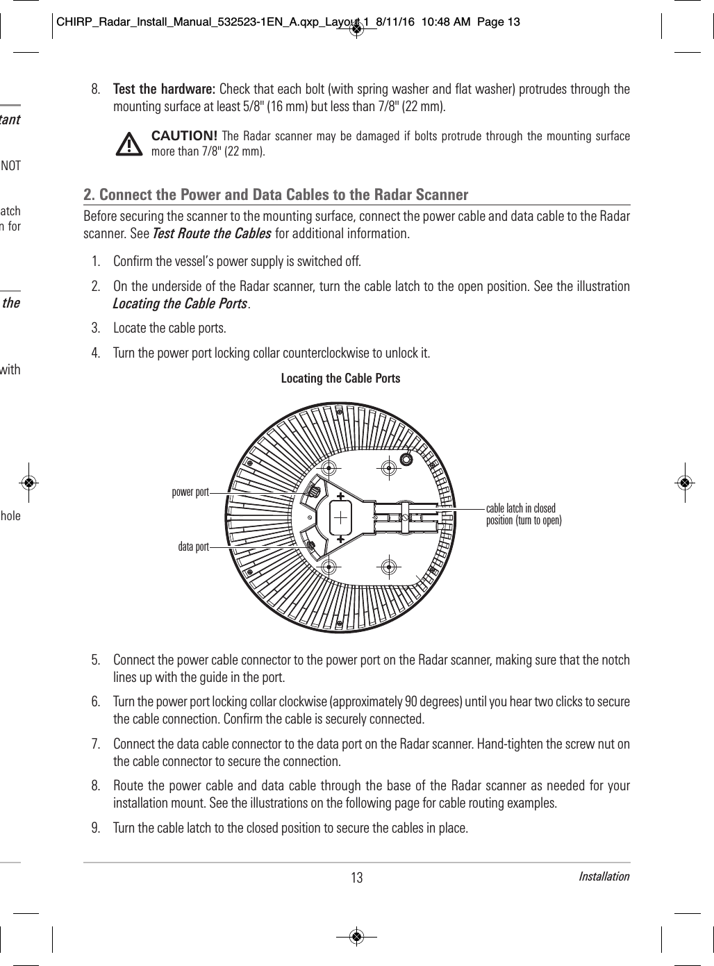
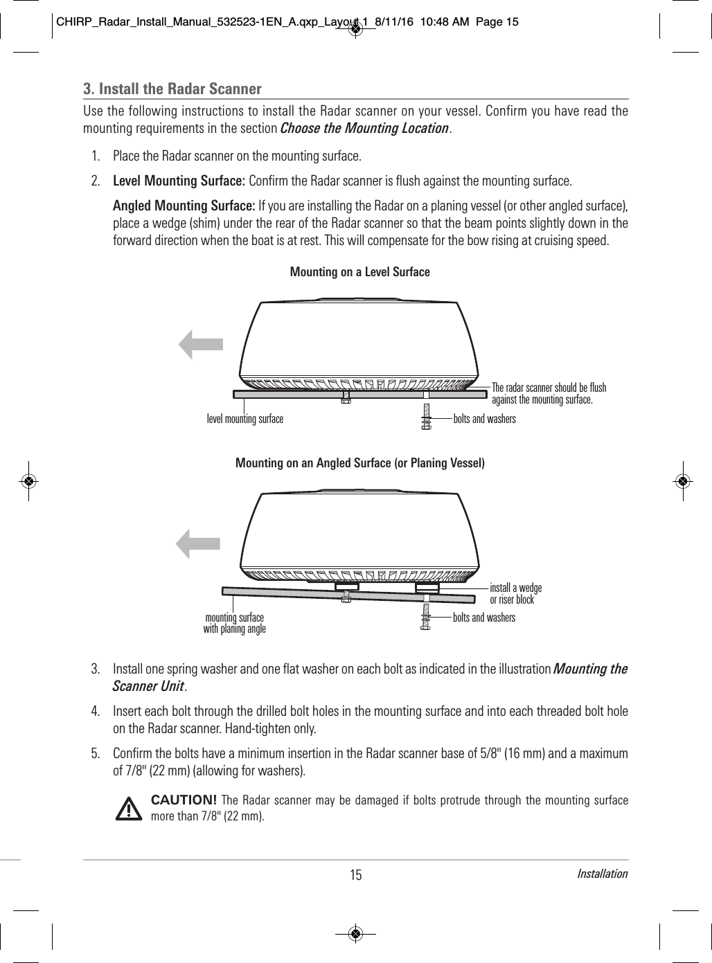
UserManual.wiki
>
Flir BelgiumBA
>
HB2124 User Manual
User manual
Navigation menu
Upload a User Manual
Namespaces
Wiki Guide
HTML
PDF
Info
Views
User Manual
Discussion / Help
Navigation
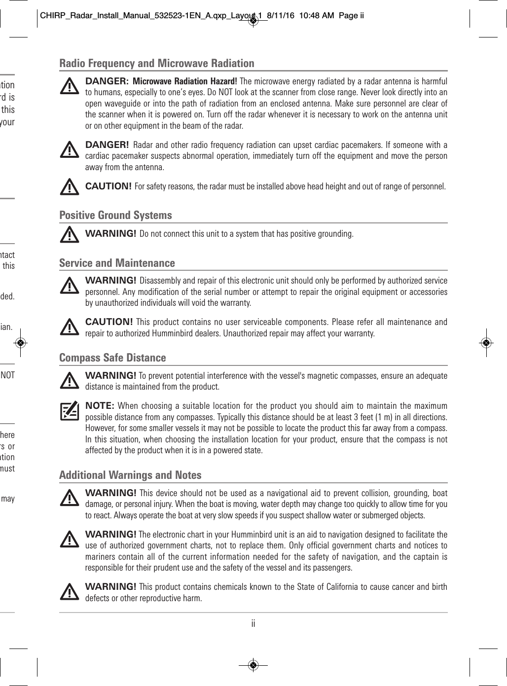
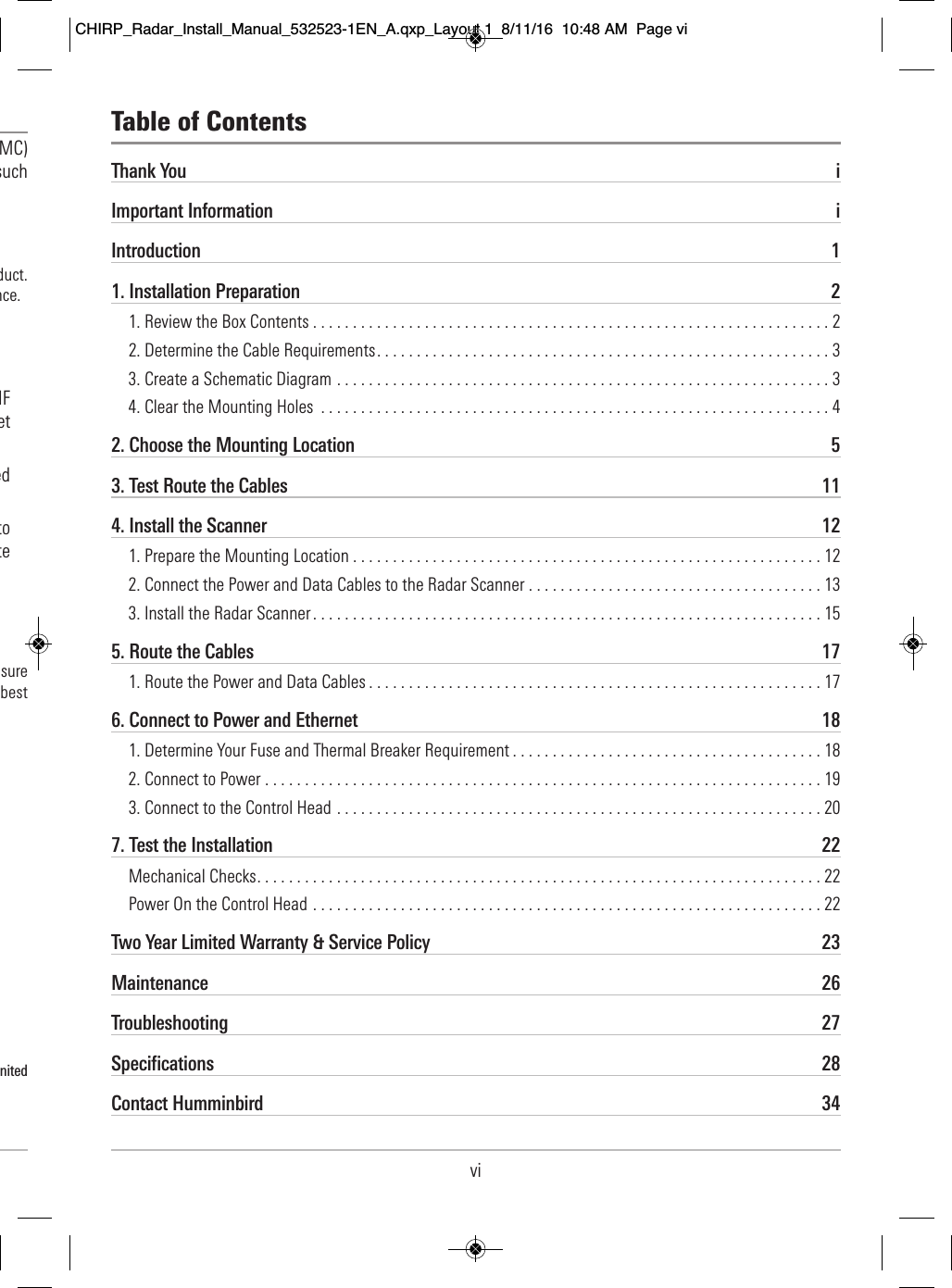
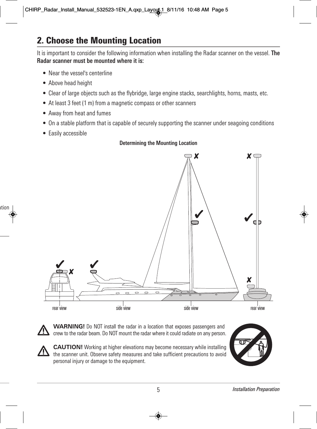
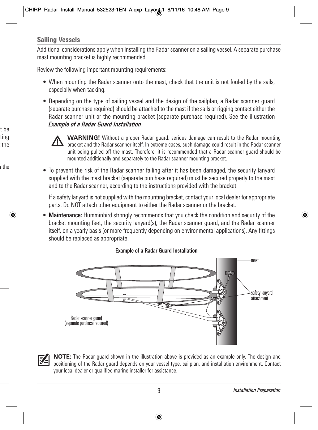
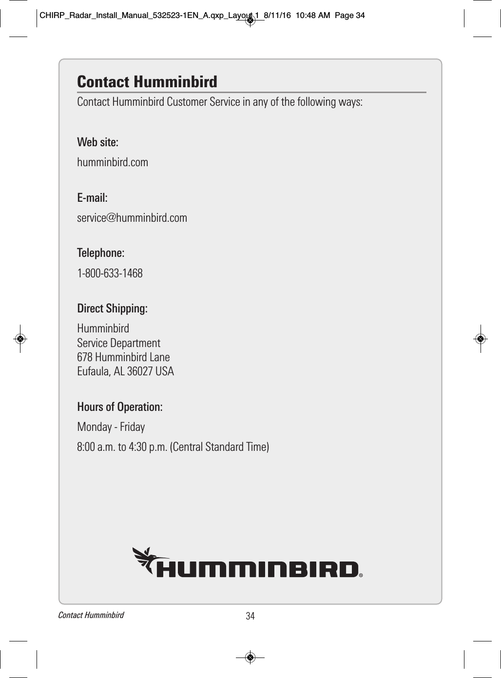
![1. Installation PreparationFollowing are instructions for the installation of this accessory. Before you start installation, we encourageyou to read these instructions carefully in order to get the full benefit from your Humminbird accessory.Supplies: In addition to the hardware included in this box, you will need a separate 12 or 24 VDC powersupply from that used for engine start, adhesive tape, a powered hand drill and various drill bits, varioushand tools, safety glasses, and a dust mask.NOTE: It is important that you have read and understood the warnings and cautions provided in theImportant Information section of this manual before proceeding with the installation.NOTE: A separate 12/24 VDC power supply is required for the Radar scanner installation to prevent erraticbehavior and data loss, which can occur if the engine start does not have a separate power supply.1. Review the Box ContentsAlso, see the Specifications section for additional product information.1. Unpack the box and confirm the contents with the illustration shown below. CAUTION! Do not remove the cover from the unit. There are no connections or adjustments insidethe unit that are needed for installation or operation. NOTE: Product supplies and features are subject to change without notice.Parts Supplied(1) Radar scanner(1) AS EC M12to RM data cable(32.8 ft [10 m])(1) power cable(32.8 ft [10 m])(4) flat washers(4) spring washers(4) M8 mounting bolts2Installation Preparation2. D Dep acce insta Also 3. C A sc or m • • O CHIRP_Radar_Install_Manual_532523-1EN_A.qxp_Layout 1 8/11/16 10:48 AM Page 2](https://usermanual.wiki/Flir-BelgiumBA/HB2124/User-Guide-3136060-Page-10.png)
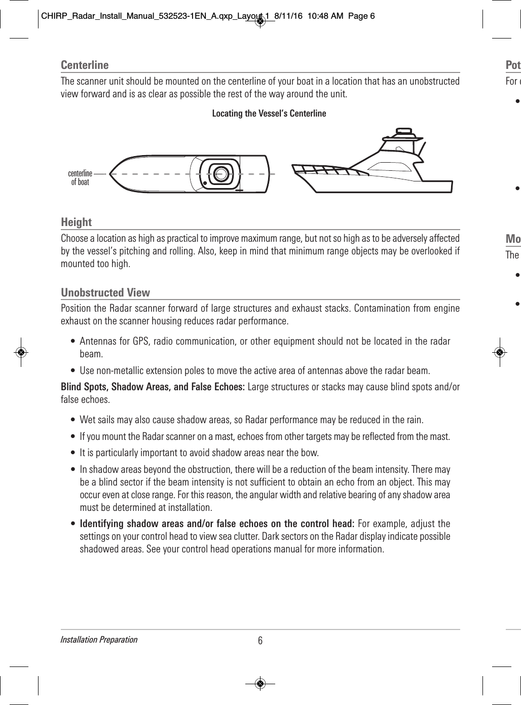
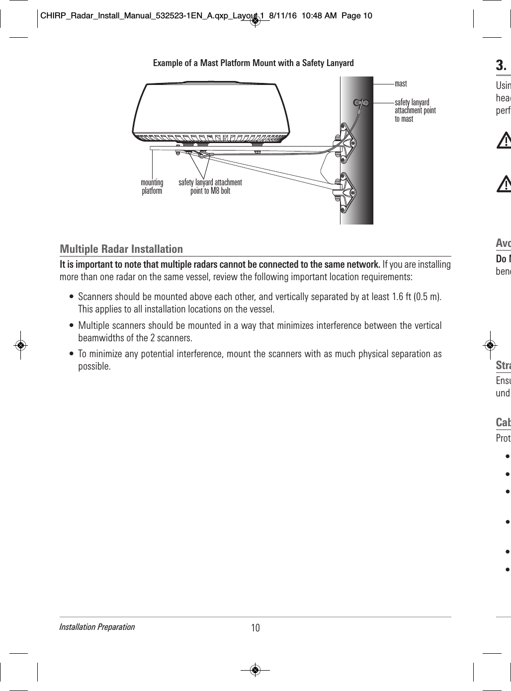
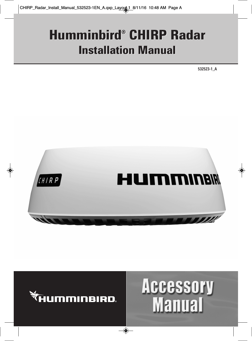
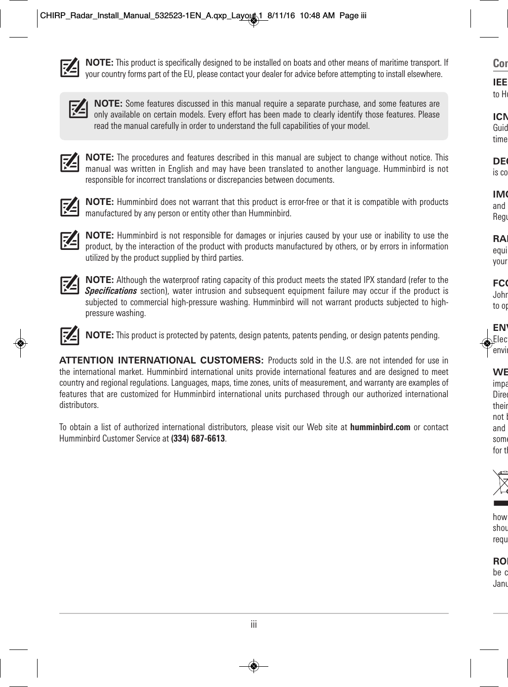
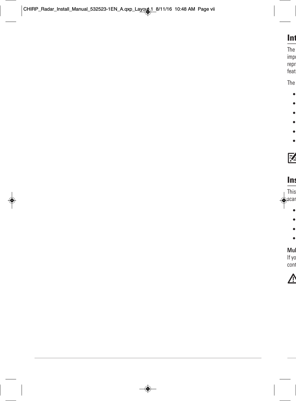
![3Installation Preparation rage y. ower ious the ratic nside s bolts2. Determine the Cable RequirementsDepending on your Humminbird model and network configuration, you may need to purchase additionalaccessories to connect your Radar scanner to your control head or Ethernet network. Before starting theinstallation, determine whether you will need to purchase Ethernet Adapter Cables or extension cables.Also, see Connect to Power and Ethernet for more information.NOTE: To purchase Ethernet Accessory Cables, extension cables, or the Ethernet Switch, visit our Web siteat humminbird.com or call Humminbird Customer Service at 1-800-633-1468.3. Create a Schematic DiagramA schematic diagram is an essential part of planning any installation. It is also useful for any future additionsor maintenance of the system. The diagram should include the following:• Location of all components• Cable types, routes, and lengths.NOTE: Confirm that you have read and understood the warnings and cautions provided in the ImportantInformation section before proceeding with the installation.Hardware Cable Requirement to Connect to Radar Scanner Voltage RequirementsONIX No additional cables required. 12 VDCHELIX Separate purchase AS EC QDE Ethernet AdapterCable is required. 12 VDCEthernet Switch No additional cables required. 12 or 24 VDCExample of a Schematic Diagram with a Direct Connection to the Control HeadRadar scanner control head power cable(6 ft [2 m])Radar scannerpower cable(32.8 ft [10 m])control headpower supplyAS EC M12 to RM data cable (included)(32.8 ft [10 m])ONIX control head separate 12/24 Vpower supplyCHIRP_Radar_Install_Manual_532523-1EN_A.qxp_Layout 1 8/11/16 10:48 AM Page 3](https://usermanual.wiki/Flir-BelgiumBA/HB2124/User-Guide-3136060-Page-11.png)
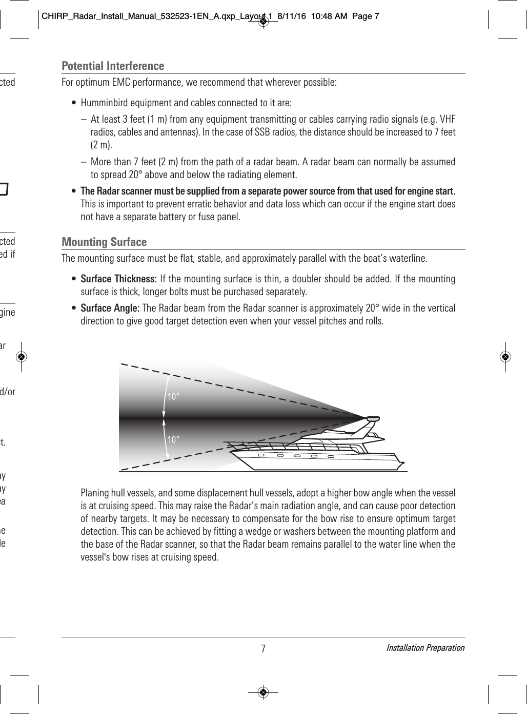
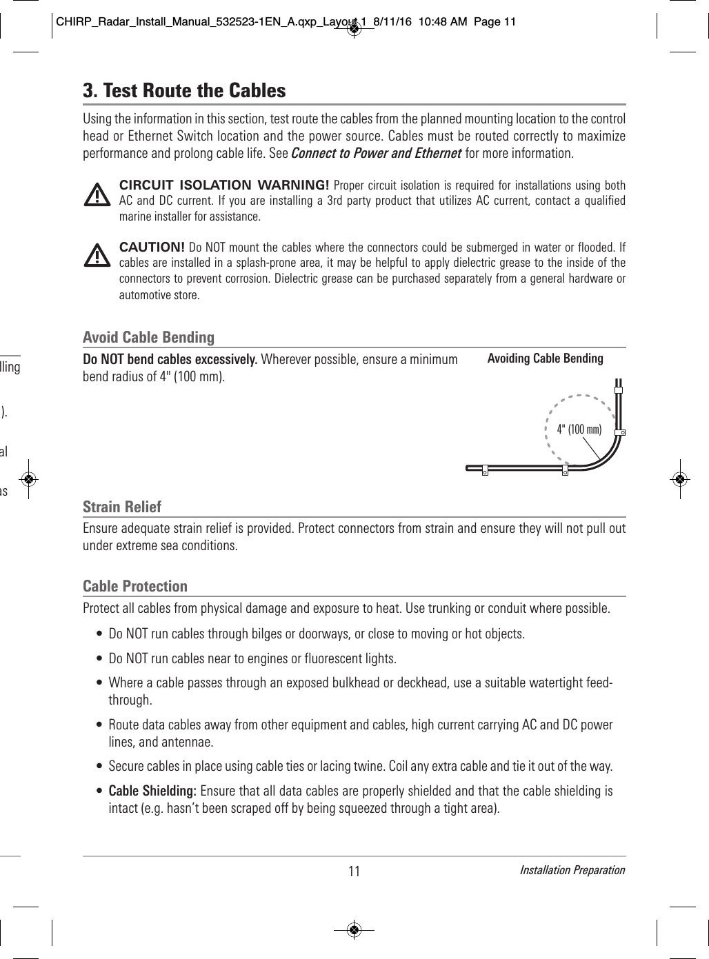
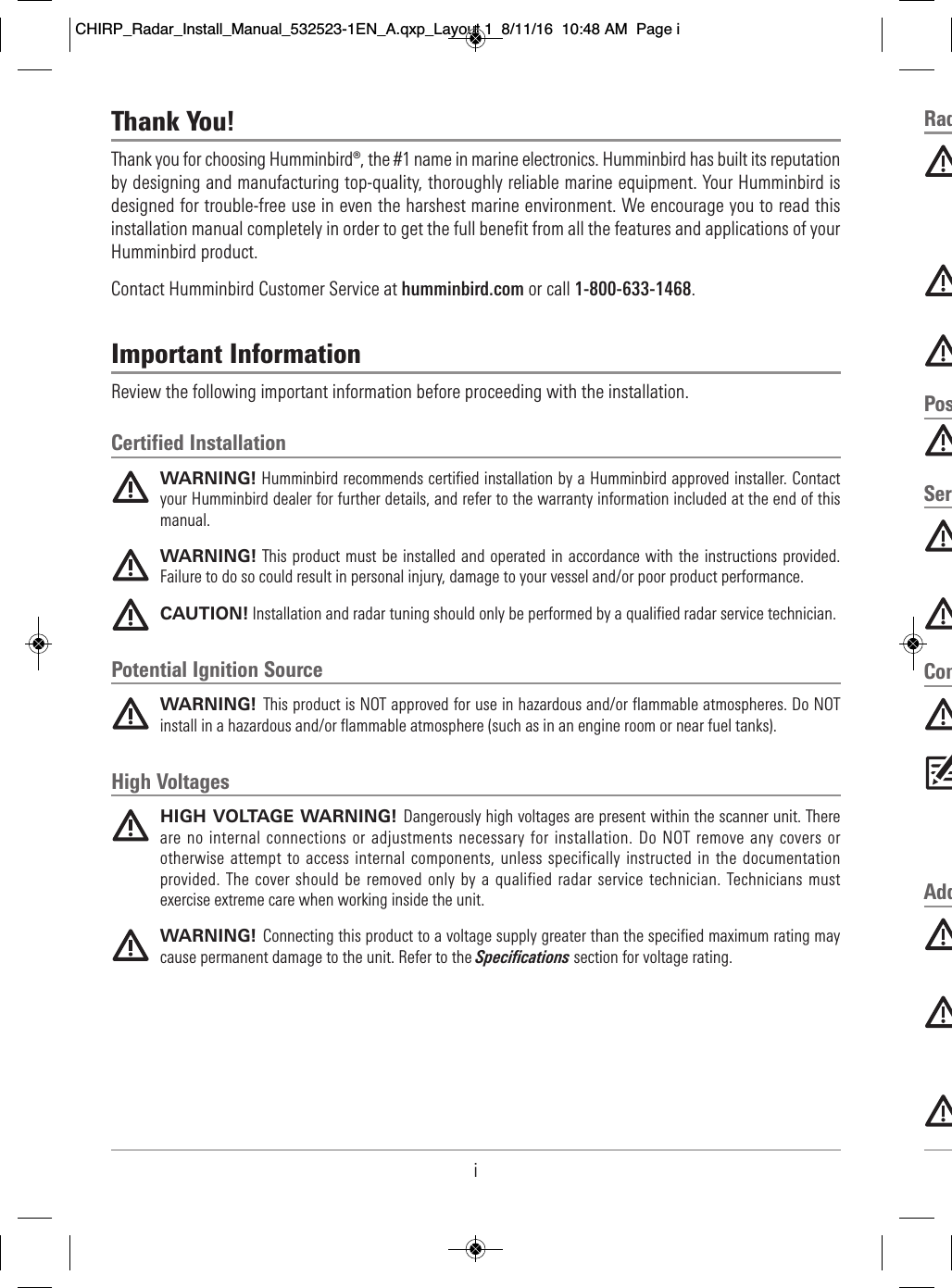
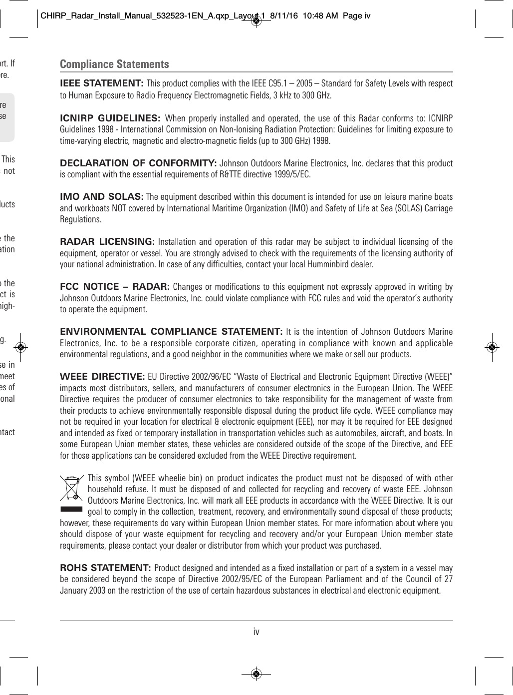
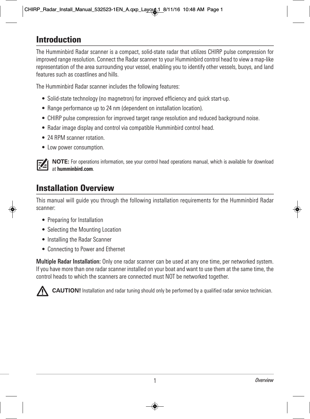
![4Installation Preparation2. It is Rad • • • • • • • NOTE: Cable lengths and power voltage requirements vary per model. Refer to the installationguides included with your products for additional information.4. Clear the Mounting Holes1. Invert the scanner.2. Confirm the four mounting holes are clear so they can accept the bolts.Example of a Schematic Diagram with an Ethernet Switch ConnectionRadar scannercontrol head power cable(lengths vary per model)Radar scanner powercable (32.8 ft [10 m])Ethernet SwitchAS EC M12 to RM data cable(32.8 ft [10 m])AS EC QDE adapter cable (12 in [304.8 mm])(separate purchase required)Ethernet Switchpower supplycontrol headpower supplyEthernet Switchpower cableseparate 12/24 Vpower supplyHELIX control headClearing the Mounting Holes(4) mounting holesCHIRP_Radar_Install_Manual_532523-1EN_A.qxp_Layout 1 8/11/16 10:48 AM Page 4](https://usermanual.wiki/Flir-BelgiumBA/HB2124/User-Guide-3136060-Page-12.png)