Flir BelgiumBA HB2124 Light Marine Navigational Radar with WLAN User Manual Layout 1
Raymarine UK Ltd. Light Marine Navigational Radar with WLAN Layout 1
User manual
532523-1_A
Humminbird®CHIRP Radar
Installation Manual
Humminbird®CHIRP Radar
Installation Manual
CHIRP_Radar_Install_Manual_532523-1EN_A.qxp_Layout 1 8/11/16 10:48 AM Page A

i
Rad
Pos
Ser
Com
Add
Thank You!
Thank you for choosing Humminbird®, the #1 name in marine electronics. Humminbird has built its reputation
by designing and manufacturing top-quality, thoroughly reliable marine equipment. Your Humminbird is
designed for trouble-free use in even the harshest marine environment. We encourage you to read this
installation manual completely in order to get the full benefit from all the features and applications of your
Humminbird product.
Contact Humminbird Customer Service at humminbird.com or call 1-800-633-1468.
Important Information
Review the following important information before proceeding with the installation.
Certified Installation
WARNING! Humminbird recommends certified installation by a Humminbird approved installer. Contact
your Humminbird dealer for further details, and refer to the warranty information included at the end of this
manual.
WARNING! This product must be installed and operated in accordance with the instructions provided.
Failure to do so could result in personal injury, damage to your vessel and/or poor product performance.
CAUTION! Installation and radar tuning should only be performed by a qualified radar service technician.
Potential Ignition Source
WARNING! This product is NOT approved for use in hazardous and/or flammable atmospheres. Do NOT
install in a hazardous and/or flammable atmosphere (such as in an engine room or near fuel tanks).
High Voltages
HIGH VOLTAGE WARNING! Dangerously high voltages are present within the scanner unit. There
are no internal connections or adjustments necessary for installation. Do NOT remove any covers or
otherwise attempt to access internal components, unless specifically instructed in the documentation
provided. The cover should be removed only by a qualified radar service technician. Technicians must
exercise extreme care when working inside the unit.
WARNING! Connecting this product to a voltage supply greater than the specified maximum rating may
cause permanent damage to the unit. Refer to the Specifications section for voltage rating.
CHIRP_Radar_Install_Manual_532523-1EN_A.qxp_Layout 1 8/11/16 10:48 AM Page i
ii
Radio Frequency and Microwave Radiation
DANGER: Microwave Radiation Hazard! The microwave energy radiated by a radar antenna is harmful
to humans, especially to one’s eyes. Do NOT look at the scanner from close range. Never look directly into an
open waveguide or into the path of radiation from an enclosed antenna. Make sure personnel are clear of
the scanner when it is powered on. Turn off the radar whenever it is necessary to work on the antenna unit
or on other equipment in the beam of the radar.
DANGER! Radar and other radio frequency radiation can upset cardiac pacemakers. If someone with a
cardiac pacemaker suspects abnormal operation, immediately turn off the equipment and move the person
away from the antenna.
CAUTION! For safety reasons, the radar must be installed above head height and out of range of personnel.
Positive Ground Systems
WARNING! Do not connect this unit to a system that has positive grounding.
Service and Maintenance
WARNING! Disassembly and repair of this electronic unit should only be performed by authorized service
personnel. Any modification of the serial number or attempt to repair the original equipment or accessories
by unauthorized individuals will void the warranty.
CAUTION! This product contains no user serviceable components. Please refer all maintenance and
repair to authorized Humminbird dealers. Unauthorized repair may affect your warranty.
Compass Safe Distance
WARNING! To prevent potential interference with the vessel's magnetic compasses, ensure an adequate
distance is maintained from the product.
NOTE: When choosing a suitable location for the product you should aim to maintain the maximum
possible distance from any compasses. Typically this distance should be at least 3 feet (1 m) in all directions.
However, for some smaller vessels it may not be possible to locate the product this far away from a compass.
In this situation, when choosing the installation location for your product, ensure that the compass is not
affected by the product when it is in a powered state.
Additional Warnings and Notes
WARNING! This device should not be used as a navigational aid to prevent collision, grounding, boat
damage, or personal injury. When the boat is moving, water depth may change too quickly to allow time for you
to react. Always operate the boat at very slow speeds if you suspect shallow water or submerged objects.
WARNING! The electronic chart in your Humminbird unit is an aid to navigation designed to facilitate the
use of authorized government charts, not to replace them. Only official government charts and notices to
mariners contain all of the current information needed for the safety of navigation, and the captain is
responsible for their prudent use and the safety of the vessel and its passengers.
WARNING! This product contains chemicals known to the State of California to cause cancer and birth
defects or other reproductive harm.
ation
rd is
this
your
ntact
this
ded.
cian.
NOT
here
rs or
ation
must
may
CHIRP_Radar_Install_Manual_532523-1EN_A.qxp_Layout 1 8/11/16 10:48 AM Page ii

Com
IEE
to Hu
ICN
Guid
time
DEC
is co
IMO
and
Regu
RAD
equi
your
FCC
John
to op
ENV
Elect
envir
WE
impa
Direc
their
not b
and
some
for th
how
shou
requ
ROH
be c
Janu
NOTE: This product is specifically designed to be installed on boats and other means of maritime transport. If
your country forms part of the EU, please contact your dealer for advice before attempting to install elsewhere.
NOTE: The procedures and features described in this manual are subject to change without notice. This
manual was written in English and may have been translated to another language. Humminbird is not
responsible for incorrect translations or discrepancies between documents.
NOTE: Humminbird does not warrant that this product is error-free or that it is compatible with products
manufactured by any person or entity other than Humminbird.
NOTE: Humminbird is not responsible for damages or injuries caused by your use or inability to use the
product, by the interaction of the product with products manufactured by others, or by errors in information
utilized by the product supplied by third parties.
NOTE: Although the waterproof rating capacity of this product meets the stated IPX standard (refer to the
Specifications section), water intrusion and subsequent equipment failure may occur if the product is
subjected to commercial high-pressure washing. Humminbird will not warrant products subjected to high-
pressure washing.
NOTE: This product is protected by patents, design patents, patents pending, or design patents pending.
ATTENTION INTERNATIONAL CUSTOMERS: Products sold in the U.S. are not intended for use in
the international market. Humminbird international units provide international features and are designed to meet
country and regional regulations. Languages, maps, time zones, units of measurement, and warranty are examples of
features that are customized for Humminbird international units purchased through our authorized international
distributors.
To obtain a list of authorized international distributors, please visit our Web site at humminbird.com or contact
Humminbird Customer Service at (334) 687-6613.
NOTE: Some features discussed in this manual require a separate purchase, and some features are
only available on certain models. Every effort has been made to clearly identify those features. Please
read the manual carefully in order to understand the full capabilities of your model.
iii
CHIRP_Radar_Install_Manual_532523-1EN_A.qxp_Layout 1 8/11/16 10:48 AM Page iii

Compliance Statements
IEEE STATEMENT: This product complies with the IEEE C95.1 – 2005 – Standard for Safety Levels with respect
to Human Exposure to Radio Frequency Electromagnetic Fields, 3 kHz to 300 GHz.
ICNIRP GUIDELINES: When properly installed and operated, the use of this Radar conforms to: ICNIRP
Guidelines 1998 - International Commission on Non-Ionising Radiation Protection: Guidelines for limiting exposure to
time-varying electric, magnetic and electro-magnetic fields (up to 300 GHz) 1998.
DECLARATION OF CONFORMITY: Johnson Outdoors Marine Electronics, Inc. declares that this product
is compliant with the essential requirements of R&TTE directive 1999/5/EC.
IMO AND SOLAS: The equipment described within this document is intended for use on leisure marine boats
and workboats NOT covered by International Maritime Organization (IMO) and Safety of Life at Sea (SOLAS) Carriage
Regulations.
RADAR LICENSING: Installation and operation of this radar may be subject to individual licensing of the
equipment, operator or vessel. You are strongly advised to check with the requirements of the licensing authority of
your national administration. In case of any difficulties, contact your local Humminbird dealer.
FCC NOTICE – RADAR: Changes or modifications to this equipment not expressly approved in writing by
Johnson Outdoors Marine Electronics, Inc. could violate compliance with FCC rules and void the operator’s authority
to operate the equipment.
ENVIRONMENTAL COMPLIANCE STATEMENT: It is the intention of Johnson Outdoors Marine
Electronics, Inc. to be a responsible corporate citizen, operating in compliance with known and applicable
environmental regulations, and a good neighbor in the communities where we make or sell our products.
WEEE DIRECTIVE: EU Directive 2002/96/EC “Waste of Electrical and Electronic Equipment Directive (WEEE)”
impacts most distributors, sellers, and manufacturers of consumer electronics in the European Union. The WEEE
Directive requires the producer of consumer electronics to take responsibility for the management of waste from
their products to achieve environmentally responsible disposal during the product life cycle. WEEE compliance may
not be required in your location for electrical & electronic equipment (EEE), nor may it be required for EEE designed
and intended as fixed or temporary installation in transportation vehicles such as automobiles, aircraft, and boats. In
some European Union member states, these vehicles are considered outside of the scope of the Directive, and EEE
for those applications can be considered excluded from the WEEE Directive requirement.
This symbol (WEEE wheelie bin) on product indicates the product must not be disposed of with other
household refuse. It must be disposed of and collected for recycling and recovery of waste EEE. Johnson
Outdoors Marine Electronics, Inc. will mark all EEE products in accordance with the WEEE Directive. It is our
goal to comply in the collection, treatment, recovery, and environmentally sound disposal of those products;
however, these requirements do vary within European Union member states. For more information about where you
should dispose of your waste equipment for recycling and recovery and/or your European Union member state
requirements, please contact your dealer or distributor from which your product was purchased.
ROHS STATEMENT: Product designed and intended as a fixed installation or part of a system in a vessel may
be considered beyond the scope of Directive 2002/95/EC of the European Parliament and of the Council of 27
January 2003 on the restriction of the use of certain hazardous substances in electrical and electronic equipment.
iv
ort. If
ere.
This
s not
ducts
e the
ation
o the
ct is
high-
g.
se in
meet
es of
onal
ntact
re
se
CHIRP_Radar_Install_Manual_532523-1EN_A.qxp_Layout 1 8/11/16 10:48 AM Page iv

EMC Installation Guidelines
Humminbird equipment and accessories conform to the appropriate Electromagnetic Compatibility (EMC)
regulations, to minimize electromagnetic interference between equipment and minimize the effect such
interference could have on the performance of your system.
Correct installation is required to ensure that EMC performance is not compromised.
NOTE: In areas of extreme EMC interference, some slight interference may be noticed on the product.
Where this occurs the product and the source of the interference should be separated by a greater distance.
For optimum EMC performance, we recommend that wherever possible:
• Humminbird equipment and cables connected to it are:
– At least 3 feet (1 m) from any equipment transmitting or cables carrying radio signals (e.g. VHF
radios, cables and antennas). In the case of SSB radios, the distance should be increased to 7 feet
(2 m).
– More than 7 feet (2 m) from the path of a radar beam. A radar beam can normally be assumed
to spread 20 degrees above and below the radiating element.
• The product is supplied from a separate battery from that used for engine start. This is important to
prevent erratic behavior and data loss which can occur if the engine start does not have a separate
battery.
• Humminbird specified cables are used.
• Cables are not cut or extended, unless doing so is detailed in the installation manual.
NOTE: Where constraints on the installation prevent any of the above recommendations, always ensure
the maximum possible separation between different items of electrical equipment, to provide the best
conditions for EMC performance throughout the installation.
HELIX™, Humminbird®, and ONIX® are trademarked by or registered trademarks of Johnson Outdoors Marine Electronics, Inc.
Adobe, Acrobat, Adobe PDF, and Reader are either registered trademarks or trademarks of Adobe Systems Incorporated in the United
States and/or other countries.
© 2016 Johnson Outdoors Marine Electronics, Inc. All rights reserved.
v
Than
Imp
Intro
1. In
1.
2.
3.
4.
2. C
3. Te
4. In
1.
2.
3.
5. R
1.
6. C
1.
2.
3.
7. Te
M
Po
Two
Mai
Trou
Spe
Con
Tab
CHIRP_Radar_Install_Manual_532523-1EN_A.qxp_Layout 1 8/11/16 10:48 AM Page v

vi
MC)
such
duct.
nce.
HF
et
ed
to
te
sure
best
nited
Thank You i
Important Information i
Introduction 1
1. Installation Preparation 2
1. Review the Box Contents . . . . . . . . . . . . . . . . . . . . . . . . . . . . . . . . . . . . . . . . . . . . . . . . . . . . . . . . . . . . . . . . . 2
2. Determine the Cable Requirements. . . . . . . . . . . . . . . . . . . . . . . . . . . . . . . . . . . . . . . . . . . . . . . . . . . . . . . . . 3
3. Create a Schematic Diagram . . . . . . . . . . . . . . . . . . . . . . . . . . . . . . . . . . . . . . . . . . . . . . . . . . . . . . . . . . . . . . 3
4. Clear the Mounting Holes . . . . . . . . . . . . . . . . . . . . . . . . . . . . . . . . . . . . . . . . . . . . . . . . . . . . . . . . . . . . . . . . 4
2. Choose the Mounting Location 5
3. Test Route the Cables 11
4. Install the Scanner 12
1. Prepare the Mounting Location . . . . . . . . . . . . . . . . . . . . . . . . . . . . . . . . . . . . . . . . . . . . . . . . . . . . . . . . . . . 12
2. Connect the Power and Data Cables to the Radar Scanner . . . . . . . . . . . . . . . . . . . . . . . . . . . . . . . . . . . . . 13
3. Install the Radar Scanner . . . . . . . . . . . . . . . . . . . . . . . . . . . . . . . . . . . . . . . . . . . . . . . . . . . . . . . . . . . . . . . . 15
5. Route the Cables 17
1. Route the Power and Data Cables . . . . . . . . . . . . . . . . . . . . . . . . . . . . . . . . . . . . . . . . . . . . . . . . . . . . . . . . . 17
6. Connect to Power and Ethernet 18
1. Determine Your Fuse and Thermal Breaker Requirement . . . . . . . . . . . . . . . . . . . . . . . . . . . . . . . . . . . . . . . 18
2. Connect to Power . . . . . . . . . . . . . . . . . . . . . . . . . . . . . . . . . . . . . . . . . . . . . . . . . . . . . . . . . . . . . . . . . . . . . . 19
3. Connect to the Control Head . . . . . . . . . . . . . . . . . . . . . . . . . . . . . . . . . . . . . . . . . . . . . . . . . . . . . . . . . . . . . 20
7. Test the Installation 22
Mechanical Checks. . . . . . . . . . . . . . . . . . . . . . . . . . . . . . . . . . . . . . . . . . . . . . . . . . . . . . . . . . . . . . . . . . . . . . . 22
Power On the Control Head . . . . . . . . . . . . . . . . . . . . . . . . . . . . . . . . . . . . . . . . . . . . . . . . . . . . . . . . . . . . . . . . 22
Two Year Limited Warranty & Service Policy 23
Maintenance 26
Troubleshooting 27
Specifications 28
Contact Humminbird 34
Table of Contents
CHIRP_Radar_Install_Manual_532523-1EN_A.qxp_Layout 1 8/11/16 10:48 AM Page vi

Int
The
impr
repr
feat
The
•
•
•
•
•
•
Ins
This
scan
•
•
•
•
Mul
If yo
cont
CHIRP_Radar_Install_Manual_532523-1EN_A.qxp_Layout 1 8/11/16 10:48 AM Page vii

1Overview
Introduction
The Humminbird Radar scanner is a compact, solid-state radar that utilizes CHIRP pulse compression for
improved range resolution. Connect the Radar scanner to your Humminbird control head to view a map-like
representation of the area surrounding your vessel, enabling you to identify other vessels, buoys, and land
features such as coastlines and hills.
The Humminbird Radar scanner includes the following features:
• Solid-state technology (no magnetron) for improved efficiency and quick start-up.
• Range performance up to 24 nm (dependent on installation location).
• CHIRP pulse compression for improved target range resolution and reduced background noise.
• Radar image display and control via compatible Humminbird control head.
• 24 RPM scanner rotation.
• Low power consumption.
NOTE: For operations information, see your control head operations manual, which is available for download
at humminbird.com.
Installation Overview
This manual will guide you through the following installation requirements for the Humminbird Radar
scanner:
• Preparing for Installation
• Selecting the Mounting Location
• Installing the Radar Scanner
• Connecting to Power and Ethernet
Multiple Radar Installation: Only one radar scanner can be used at any one time, per networked system.
If you have more than one radar scanner installed on your boat and want to use them at the same time, the
control heads to which the scanners are connected must NOT be networked together.
CAUTION! Installation and radar tuning should only be performed by a qualified radar service technician.
CHIRP_Radar_Install_Manual_532523-1EN_A.qxp_Layout 1 8/11/16 10:48 AM Page 1
1. Installation Preparation
Following are instructions for the installation of this accessory. Before you start installation, we encourage
you to read these instructions carefully in order to get the full benefit from your Humminbird accessory.
Supplies: In addition to the hardware included in this box, you will need a separate 12 or 24 VDC power
supply from that used for engine start, adhesive tape, a powered hand drill and various drill bits, various
hand tools, safety glasses, and a dust mask.
NOTE: It is important that you have read and understood the warnings and cautions provided in the
Important Information section of this manual before proceeding with the installation.
NOTE: A separate 12/24 VDC power supply is required for the Radar scanner installation to prevent erratic
behavior and data loss, which can occur if the engine start does not have a separate power supply.
1. Review the Box Contents
Also, see the Specifications section for additional product information.
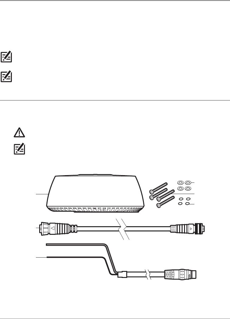
1. Unpack the box and confirm the contents with the illustration shown below.
CAUTION! Do not remove the cover from the unit. There are no connections or adjustments inside
the unit that are needed for installation or operation.
NOTE: Product supplies and features are subject to change without notice.
Parts Supplied
(1) Radar scanner
(1) AS EC M12
to RM data cable
(32.8 ft [10 m])
(1) power cable
(32.8 ft [10 m])
(4) flat washers
(4) spring washers
(4) M8 mounting bolts
2
Installation Preparation
2. D
Dep
acce
insta
Also
3. C
A sc
or m
•
•
O
CHIRP_Radar_Install_Manual_532523-1EN_A.qxp_Layout 1 8/11/16 10:48 AM Page 2
3Installation Preparation
rage
y.
ower
ious
the
ratic
nside
s
bolts
2. Determine the Cable Requirements
Depending on your Humminbird model and network configuration, you may need to purchase additional
accessories to connect your Radar scanner to your control head or Ethernet network. Before starting the
installation, determine whether you will need to purchase Ethernet Adapter Cables or extension cables.
Also, see Connect to Power and Ethernet for more information.
NOTE: To purchase Ethernet Accessory Cables, extension cables, or the Ethernet Switch, visit our Web site
at humminbird.com or call Humminbird Customer Service at 1-800-633-1468.
3. Create a Schematic Diagram
A schematic diagram is an essential part of planning any installation. It is also useful for any future additions
or maintenance of the system. The diagram should include the following:
• Location of all components
• Cable types, routes, and lengths.
NOTE: Confirm that you have read and understood the warnings and cautions provided in the Important
Information section before proceeding with the installation.
Hardware Cable Requirement to Connect to Radar Scanner Voltage Requirements
ONIX No additional cables required. 12 VDC
HELIX Separate purchase AS EC QDE Ethernet Adapter
Cable is required. 12 VDC
Ethernet Switch No additional cables required. 12 or 24 VDC
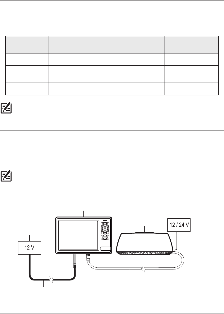
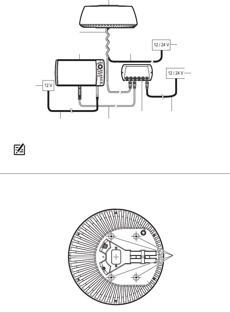
Example of a Schematic Diagram with a Direct Connection to the Control Head
Radar scanner
control head power cable
(6 ft [2 m])
Radar scanner
power cable
(32.8 ft [10 m])
control head
power supply
AS EC M12 to RM data cable (included)
(32.8 ft [10 m])
ONIX control head separate 12/24 V
power supply
CHIRP_Radar_Install_Manual_532523-1EN_A.qxp_Layout 1 8/11/16 10:48 AM Page 3
4
Installation Preparation
2.
It is
Rad
•
•
•
•
•
•
•
NOTE: Cable lengths and power voltage requirements vary per model. Refer to the installation
guides included with your products for additional information.
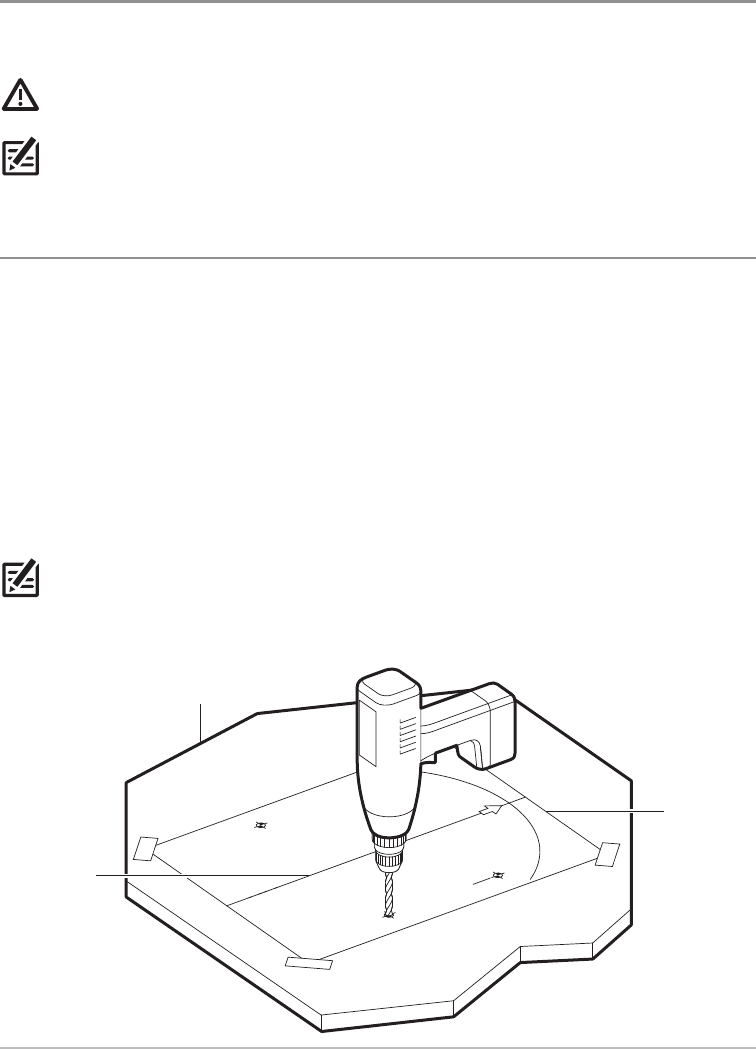
4. Clear the Mounting Holes
1. Invert the scanner.
2. Confirm the four mounting holes are clear so they can accept the bolts.
Example of a Schematic Diagram with an Ethernet Switch Connection
Radar scanner
control head power cable
(lengths vary per model)
Radar scanner power
cable (32.8 ft [10 m])
Ethernet Switch
AS EC M12 to RM data cable
(32.8 ft [10 m])
AS EC QDE adapter cable
(12 in [304.8 mm])
(separate purchase required)
Ethernet Switch
power supply
control head
power supply
Ethernet Switch
power cable
separate 12/24 V
power supply
HELIX control head
Clearing the Mounting Holes
(4) mounting holes
CHIRP_Radar_Install_Manual_532523-1EN_A.qxp_Layout 1 8/11/16 10:48 AM Page 4
5Installation Preparation
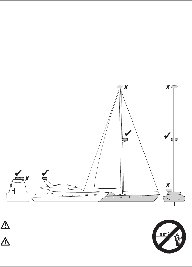
2. Choose the Mounting Location
It is important to consider the following information when installing the Radar scanner on the vessel. The
Radar scanner must be mounted where it is:
• Near the vessel's centerline
• Above head height
• Clear of large objects such as the flybridge, large engine stacks, searchlights, horns, masts, etc.
• At least 3 feet (1 m) from a magnetic compass or other scanners
• Away from heat and fumes
• On a stable platform that is capable of securely supporting the scanner under seagoing conditions
• Easily accessible
WARNING! Do NOT install the radar in a location that exposes passengers and
crew to the radar beam. Do NOT mount the radar where it could radiate on any person.
CAUTION! Working at higher elevations may become necessary while installing
the scanner unit. Observe safety measures and take sufficient precautions to avoid
personal injury or damage to the equipment.
Determining the Mounting Location
rear view side view side view rear view
ation
CHIRP_Radar_Install_Manual_532523-1EN_A.qxp_Layout 1 8/11/16 10:48 AM Page 5
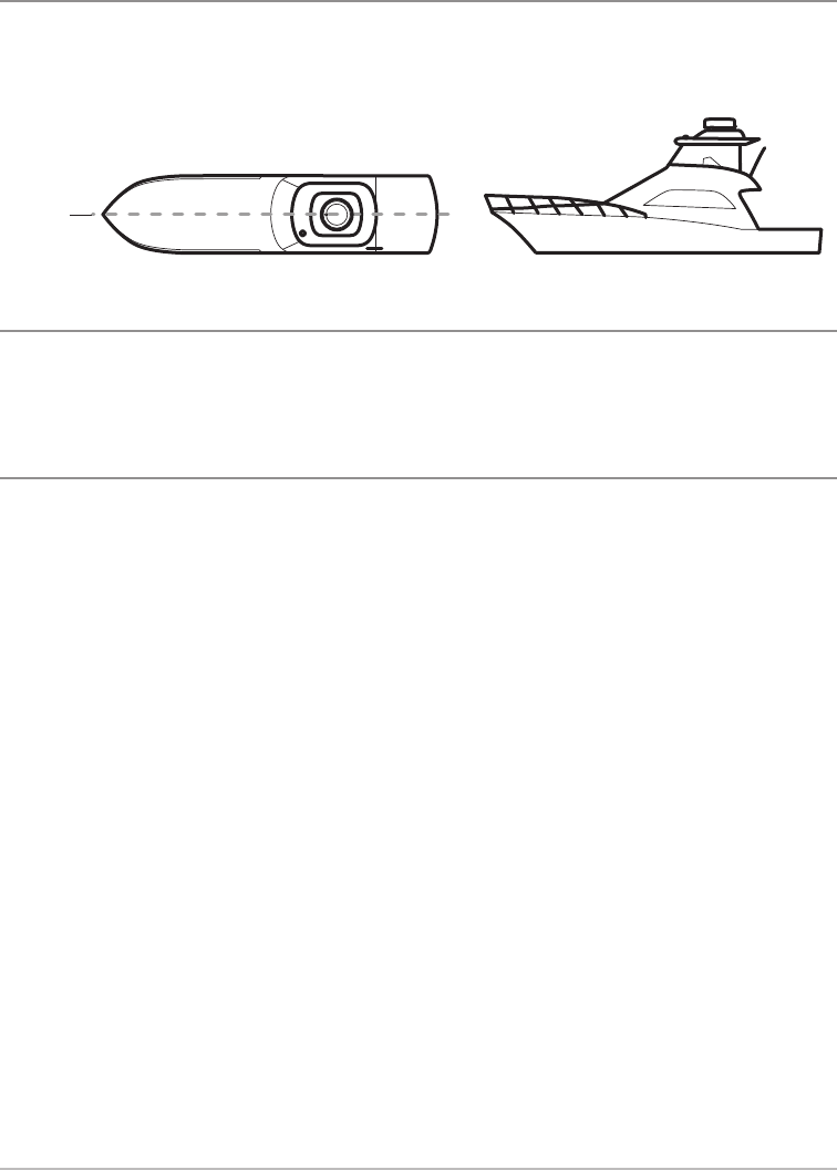
Centerline
The scanner unit should be mounted on the centerline of your boat in a location that has an unobstructed
view forward and is as clear as possible the rest of the way around the unit.
Height
Choose a location as high as practical to improve maximum range, but not so high as to be adversely affected
by the vessel’s pitching and rolling. Also, keep in mind that minimum range objects may be overlooked if
mounted too high.
Unobstructed View
Position the Radar scanner forward of large structures and exhaust stacks. Contamination from engine
exhaust on the scanner housing reduces radar performance.
• Antennas for GPS, radio communication, or other equipment should not be located in the radar
beam.
• Use non-metallic extension poles to move the active area of antennas above the radar beam.
Blind Spots, Shadow Areas, and False Echoes: Large structures or stacks may cause blind spots and/or
false echoes.
• Wet sails may also cause shadow areas, so Radar performance may be reduced in the rain.
• If you mount the Radar scanner on a mast, echoes from other targets may be reflected from the mast.
• It is particularly important to avoid shadow areas near the bow.
• In shadow areas beyond the obstruction, there will be a reduction of the beam intensity. There may
be a blind sector if the beam intensity is not sufficient to obtain an echo from an object. This may
occur even at close range. For this reason, the angular width and relative bearing of any shadow area
must be determined at installation.
•Identifying shadow areas and/or false echoes on the control head: For example, adjust the
settings on your control head to view sea clutter. Dark sectors on the Radar display indicate possible
shadowed areas. See your control head operations manual for more information.
Locating the Vessel’s Centerline
centerline
of boat
6
Installation Preparation
Pot
For o
•
•
Mo
The
•
•
CHIRP_Radar_Install_Manual_532523-1EN_A.qxp_Layout 1 8/11/16 10:48 AM Page 6
7Installation Preparation
cted
cted
ed if
gine
ar
d/or
st.
ay
ay
ea
he
le
Potential Interference
For optimum EMC performance, we recommend that wherever possible:
• Humminbird equipment and cables connected to it are:
– At least 3 feet (1 m) from any equipment transmitting or cables carrying radio signals (e.g. VHF
radios, cables and antennas). In the case of SSB radios, the distance should be increased to 7 feet
(2 m).
– More than 7 feet (2 m) from the path of a radar beam. A radar beam can normally be assumed
to spread 20° above and below the radiating element.
•The Radar scanner must be supplied from a separate power source from that used for engine start.
This is important to prevent erratic behavior and data loss which can occur if the engine start does
not have a separate battery or fuse panel.
Mounting Surface
The mounting surface must be flat, stable, and approximately parallel with the boat’s waterline.
•Surface Thickness: If the mounting surface is thin, a doubler should be added. If the mounting
surface is thick, longer bolts must be purchased separately.
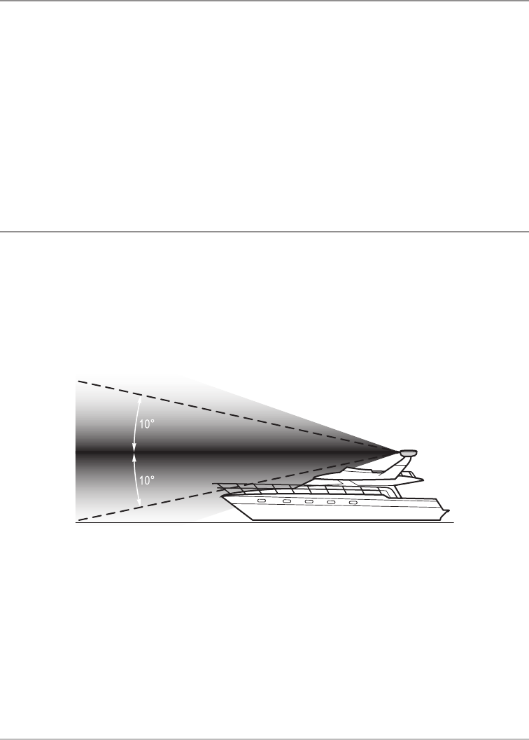
•Surface Angle: The Radar beam from the Radar scanner is approximately 20° wide in the vertical
direction to give good target detection even when your vessel pitches and rolls.
Planing hull vessels, and some displacement hull vessels, adopt a higher bow angle when the vessel
is at cruising speed. This may raise the Radar’s main radiation angle, and can cause poor detection
of nearby targets. It may be necessary to compensate for the bow rise to ensure optimum target
detection. This can be achieved by fitting a wedge or washers between the mounting platform and
the base of the Radar scanner, so that the Radar beam remains parallel to the water line when the
vessel's bow rises at cruising speed.
CHIRP_Radar_Install_Manual_532523-1EN_A.qxp_Layout 1 8/11/16 10:48 AM Page 7
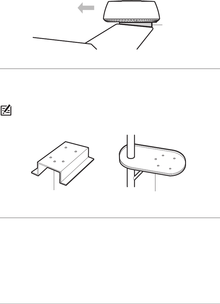
Mounting Base
The Radar scanner can be installed directly to a roof or other flat surface. The mounting location must be
secure enough to support the Radar scanner under seagoing conditions. You can also use a mounting
bracket (separate purchase required). Be certain to keep the water drain tube clear, which is located at the
bottom of the scanner unit.
NOTE: If the mounting bracket or surface has a curvature of more than 5/64" (2 mm), use spacers with the
mounting bolts to prevent stress on the scanner housing.
Access
Access to the under side is required for installation of the mounting bolts.
Compensating for Bow Rise
wedge or washers
Incorrect Mounting Base
Correct Mounting Base
mounting surface is clear and doesn’t trap water Do not mount on a surface with an edge that might trap water.
8
Installation Preparation
Sai
Add
mas
Revi
•
•
•
•
CHIRP_Radar_Install_Manual_532523-1EN_A.qxp_Layout 1 8/11/16 10:48 AM Page 8
9Installation Preparation
t be
ting
t the
h the
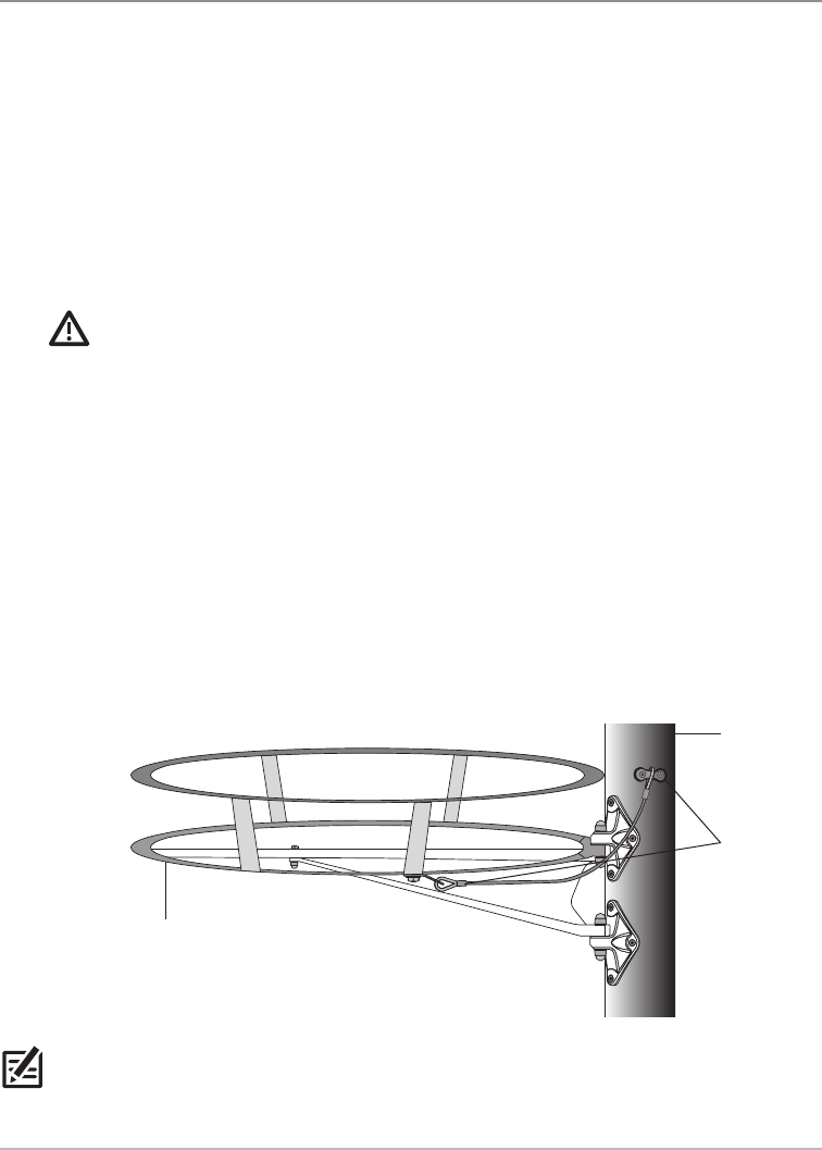
Sailing Vessels
Additional considerations apply when installing the Radar scanner on a sailing vessel. A separate purchase
mast mounting bracket is highly recommended.
Review the following important mounting requirements:
• When mounting the Radar scanner onto the mast, check that the unit is not fouled by the sails,
especially when tacking.
• Depending on the type of sailing vessel and the design of the sailplan, a Radar scanner guard
(separate purchase required) should be attached to the mast if the sails or rigging contact either the
Radar scanner unit or the mounting bracket (separate purchase required). See the illustration
Example of a Radar Guard Installation.
WARNING! Without a proper Radar guard, serious damage can result to the Radar mounting
bracket and the Radar scanner itself. In extreme cases, such damage could result in the Radar scanner
unit being pulled off the mast. Therefore, it is recommended that a Radar scanner guard should be
mounted additionally and separately to the Radar scanner mounting bracket.
• To prevent the risk of the Radar scanner falling after it has been damaged, the security lanyard
supplied with the mast bracket (separate purchase required) must be secured properly to the mast
and to the Radar scanner, according to the instructions provided with the bracket.
If a safety lanyard is not supplied with the mounting bracket, contact your local dealer for appropriate
parts. Do NOT attach other equipment to either the Radar scanner or the bracket.
•Maintenance: Humminbird strongly recommends that you check the condition and security of the
bracket mounting feet, the security lanyard(s), the Radar scanner guard, and the Radar scanner
itself, on a yearly basis (or more frequently depending on environmental applications). Any fittings
should be replaced as appropriate.
NOTE: The Radar guard shown in the illustration above is provided as an example only. The design and
positioning of the Radar guard depends on your vessel type, sailplan, and installation environment. Contact
your local dealer or qualified marine installer for assistance.
Example of a Radar Guard Installation
Radar scanner guard
(separate purchase required)
mast
safety lanyard
attachment
CHIRP_Radar_Install_Manual_532523-1EN_A.qxp_Layout 1 8/11/16 10:48 AM Page 9
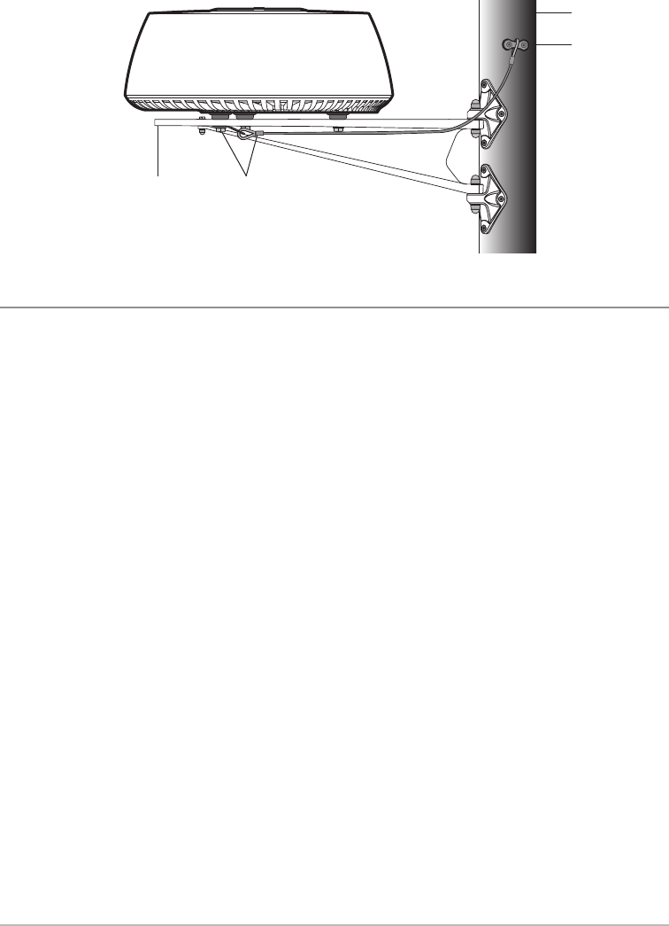
Multiple Radar Installation
It is important to note that multiple radars cannot be connected to the same network. If you are installing
more than one radar on the same vessel, review the following important location requirements:
• Scanners should be mounted above each other, and vertically separated by at least 1.6 ft (0.5 m).
This applies to all installation locations on the vessel.
• Multiple scanners should be mounted in a way that minimizes interference between the vertical
beamwidths of the 2 scanners.
• To minimize any potential interference, mount the scanners with as much physical separation as
possible.
Example of a Mast Platform Mount with a Safety Lanyard
mounting
platform safety lanyard attachment
point to M8 bolt
mast
safety lanyard
attachment point
to mast
10
Installation Preparation
3.
Usin
head
perf
Avo
Do N
bend
Stra
Ensu
und
Cab
Prot
•
•
•
•
•
•
CHIRP_Radar_Install_Manual_532523-1EN_A.qxp_Layout 1 8/11/16 10:48 AM Page 10
11 Installation Preparation
lling
).
al
as
3. Test Route the Cables
Using the information in this section, test route the cables from the planned mounting location to the control
head or Ethernet Switch location and the power source. Cables must be routed correctly to maximize
performance and prolong cable life. See Connect to Power and Ethernet for more information.
CIRCUIT ISOLATION WARNING! Proper circuit isolation is required for installations using both
AC and DC current. If you are installing a 3rd party product that utilizes AC current, contact a qualified
marine installer for assistance.
CAUTION! Do NOT mount the cables where the connectors could be submerged in water or flooded. If
cables are installed in a splash-prone area, it may be helpful to apply dielectric grease to the inside of the
connectors to prevent corrosion. Dielectric grease can be purchased separately from a general hardware or
automotive store.
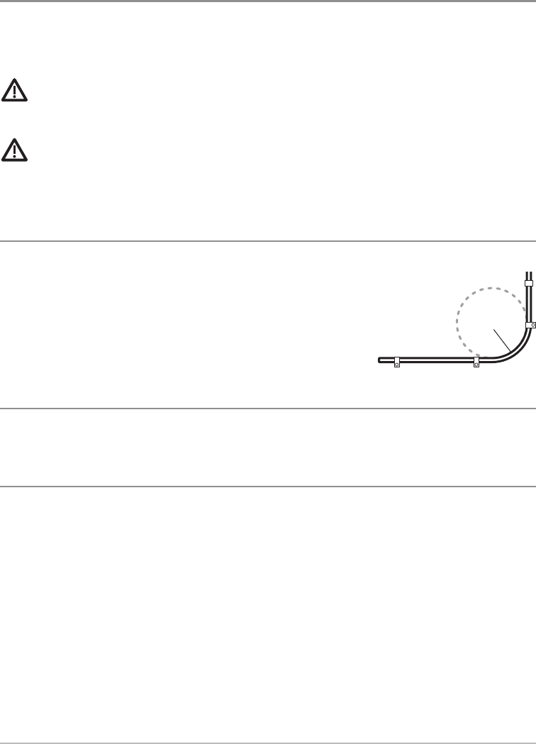
Avoid Cable Bending
Do NOT bend cables excessively. Wherever possible, ensure a minimum
bend radius of 4" (100 mm).
Strain Relief
Ensure adequate strain relief is provided. Protect connectors from strain and ensure they will not pull out
under extreme sea conditions.
Cable Protection
Protect all cables from physical damage and exposure to heat. Use trunking or conduit where possible.
• Do NOT run cables through bilges or doorways, or close to moving or hot objects.
• Do NOT run cables near to engines or fluorescent lights.
• Where a cable passes through an exposed bulkhead or deckhead, use a suitable watertight feed-
through.
• Route data cables away from other equipment and cables, high current carrying AC and DC power
lines, and antennae.
• Secure cables in place using cable ties or lacing twine. Coil any extra cable and tie it out of the way.
•Cable Shielding: Ensure that all data cables are properly shielded and that the cable shielding is
intact (e.g. hasn’t been scraped off by being squeezed through a tight area).
Avoiding Cable Bending
4" (100 mm)
CHIRP_Radar_Install_Manual_532523-1EN_A.qxp_Layout 1 8/11/16 10:48 AM Page 11
12
Installation
8.
2. C
Befo
scan
1.
2.
3.
4.
5.
6.
7.
8.
9.
4. Install the Scanner
Confirm that you have read and understood the warnings and cautions provided in the Important
Information section before proceeding with the installation.
WARNING! Confirm the vessel’s power supply is switched OFF before starting the installation. Do NOT
connect or disconnect equipment with the power switched on.
NOTE: Before proceeding with the installation, check the template to confirm that the dimensions match
the unit. Reproduction and moisture can affect the size of the template. See the Specifications section for
product dimensions.
1. Prepare the Mounting Location
1. Confirm that the mounting location meets the requirements described in the section Choose the
Mounting Location.
2. Clean and dry the mounting surface.
3. Align the included template squarely with the center line of the boat (or chosen mounting location), with
the arrow pointing forward (towards the bow of the vessel).
4. Tape the template to the chosen mounting location.
5. Mark the four mounting holes.
6. Drill four 1/8" (3 mm) pilot holes as indicated on the template.
7. Proceed to drill four 23/64" (9 mm) diameter holes through the mounting surface.
NOTE: For a close fit installation, drill 21/64" (8.5 mm) diameter holes. Do not exceed a mounting hole
diameter of 25/64" (10 mm).
mounting surface
Drilling the Mounting Holes
centerline
template
CHIRP_Radar_Install_Manual_532523-1EN_A.qxp_Layout 1 8/11/16 10:48 AM Page 12
13 Installation
8. Test the hardware: Check that each bolt (with spring washer and flat washer) protrudes through the
mounting surface at least 5/8" (16 mm) but less than 7/8" (22 mm).
CAUTION! The Radar scanner may be damaged if bolts protrude through the mounting surface
more than 7/8" (22 mm).
2. Connect the Power and Data Cables to the Radar Scanner
Before securing the scanner to the mounting surface, connect the power cable and data cable to the Radar
scanner. See Test Route the Cables for additional information.
1. Confirm the vessel’s power supply is switched off.
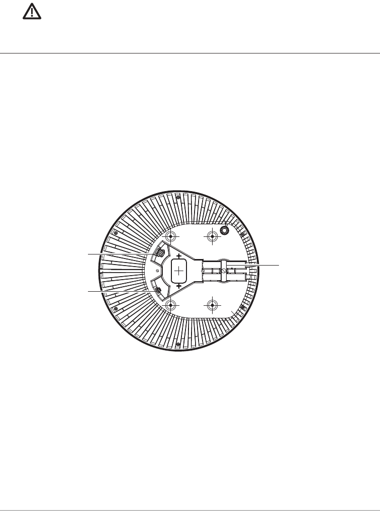
2. On the underside of the Radar scanner, turn the cable latch to the open position. See the illustration
Locating the Cable Ports.
3. Locate the cable ports.
4. Turn the power port locking collar counterclockwise to unlock it.
5. Connect the power cable connector to the power port on the Radar scanner, making sure that the notch
lines up with the guide in the port.
6. Turn the power port locking collar clockwise (approximately 90 degrees) until you hear two clicks to secure
the cable connection. Confirm the cable is securely connected.
7. Connect the data cable connector to the data port on the Radar scanner. Hand-tighten the screw nut on
the cable connector to secure the connection.
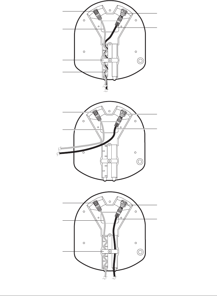
8. Route the power cable and data cable through the base of the Radar scanner as needed for your
installation mount. See the illustrations on the following page for cable routing examples.
9. Turn the cable latch to the closed position to secure the cables in place.
Locating the Cable Ports
cable latch in closed
position (turn to open)
power port
data port
tant
NOT
atch
n for
the
with
hole
CHIRP_Radar_Install_Manual_532523-1EN_A.qxp_Layout 1 8/11/16 10:48 AM Page 13
3. I
Use
mou
1.
2.
3.
4.
5.
14
Installation
cable latch in
closed position
strain relief
data port
data cable
power port
power cable
Cable Routing Examples
cable latch in
closed position
data port
data cable
power port
power cable
data port
data cable
power port
power cable
CHIRP_Radar_Install_Manual_532523-1EN_A.qxp_Layout 1 8/11/16 10:48 AM Page 14
3. Install the Radar Scanner
Use the following instructions to install the Radar scanner on your vessel. Confirm you have read the
mounting requirements in the section Choose the Mounting Location.
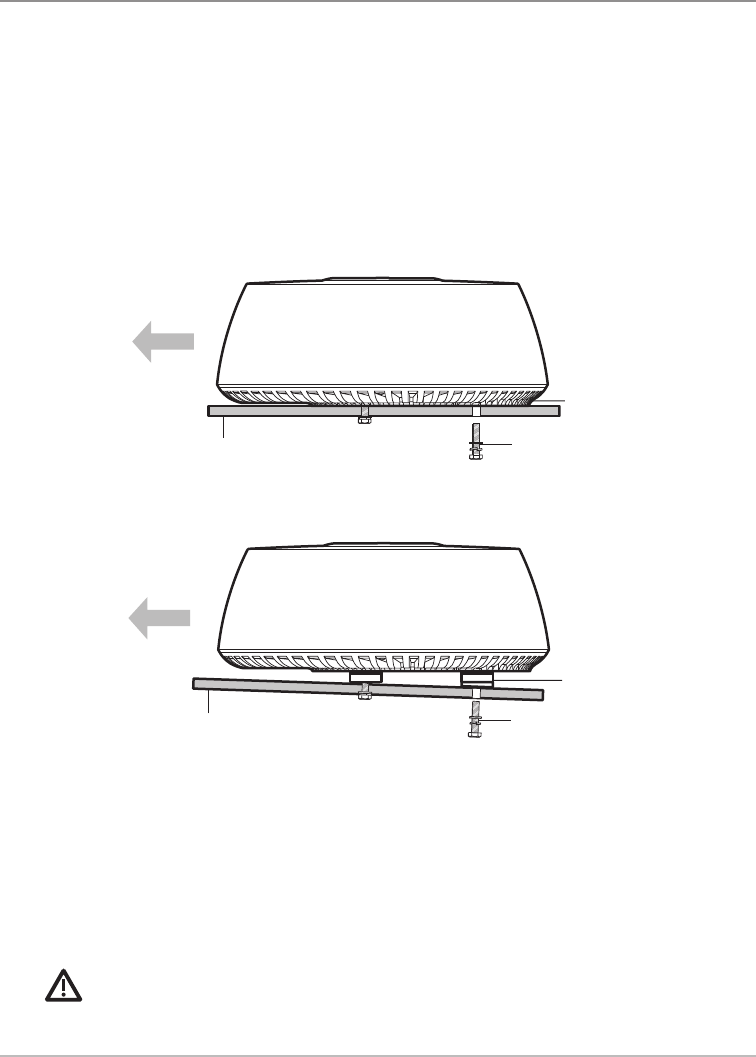
1. Place the Radar scanner on the mounting surface.
2. Level Mounting Surface: Confirm the Radar scanner is flush against the mounting surface.
Angled Mounting Surface: If you are installing the Radar on a planing vessel (or other angled surface),
place a wedge (shim) under the rear of the Radar scanner so that the beam points slightly down in the
forward direction when the boat is at rest. This will compensate for the bow rising at cruising speed.
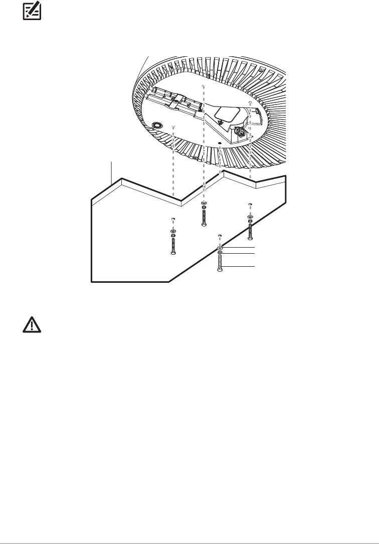
3. Install one spring washer and one flat washer on each bolt as indicated in the illustration Mounting the
Scanner Unit.
4. Insert each bolt through the drilled bolt holes in the mounting surface and into each threaded bolt hole
on the Radar scanner. Hand-tighten only.
5. Confirm the bolts have a minimum insertion in the Radar scanner base of 5/8" (16 mm) and a maximum
of 7/8" (22 mm) (allowing for washers).
CAUTION! The Radar scanner may be damaged if bolts protrude through the mounting surface
more than 7/8" (22 mm).
Mounting on an Angled Surface (or Planing Vessel)
install a wedge
or riser block
bolts and washersmounting surface
with planing angle
bolts and washers
Mounting on a Level Surface
level mounting surface
The radar scanner should be flush
against the mounting surface.
15 Installation
CHIRP_Radar_Install_Manual_532523-1EN_A.qxp_Layout 1 8/11/16 10:48 AM Page 15
5.
Afte
the c
or p
1. R
Rout
You
1.
2.
3.
4.
5.
NOTE: If you need to limit the length of the bolts entering the Radar scanner base, use appropriate
risers (shims) or additional washers.
6. Hand-tighten the bolts to a torque of 11 ft·lbf (15 Nm).
CAUTION! Do not use a high speed driver on this combination of fasteners. Hand-tighten only.
Mounting the Scanner Unit
flat washer
spring washer
bolt
mounting surface
(partial view)
16
Installation
CHIRP_Radar_Install_Manual_532523-1EN_A.qxp_Layout 1 8/11/16 10:48 AM Page 16

5. Route the Cables
After connecting the power cable and data cable to the Radar scanner unit, you must route the cables to
the control head and power source. Cable routing depends on whether you mount the scanner on a platform
or pole.
CAUTION! Confirm that the vessel’s power supply is switched off before proceeding.
CAUTION! Do NOT mount the cables where the connectors could be submerged in water or flooded. If
cables are installed in a splash-prone area, it may be helpful to apply dielectric grease to the inside of the
connectors to prevent corrosion. Dielectric grease can be purchased separately from a general hardware or
automotive store.
1. Route the Power and Data Cables
Route the power cable to the power source and the data cable to the control head or Ethernet Switch location.
You will connect the cables in a later procedure.
1. Confirm the vessel’s power supply is switched off.
2. Route the power cable to the fuse panel or battery.
3. Route the data cable to the control head or Ethernet Switch.
4. Secure the cables near the scanner to support the weight of the cables and prevent strain on the watertight
cable seals.
If the cable is to pass through tubing or a bulkhead, protect the unfinished end.
Make a drip loop and apply sealant at the entry point of an exterior bulkhead.
5. Proceed to Connect to Power and Ethernet.
CAUTION! Do not use the unfinished wires or fabric braid to pull the cable.
17 Route the Cables
riate
CHIRP_Radar_Install_Manual_532523-1EN_A.qxp_Layout 1 8/11/16 10:48 AM Page 17

6. Connect to Power and Ethernet
The power cable must be connected to a separate 12 VDC or 24 VDC power source other than that used for
engine start. Use the instructions in this section to connect the power cable to a battery or fuse panel, and
the data cable to the Humminbird control head or Ethernet Switch.
WARNING: GROUNDING NOT REQUIRED! The Radar scanner power cable is fully insulated and
does not require separate grounding.
WARNING! Humminbird is not responsible for over-voltage or over-current failures. The Radar scanner
must have adequate protection through the proper selection and installation of circuit protection (i.e. fuse,
thermal breaker, etc.).
CAUTION! Only use the power cable supplied with your product. Do not use a power cable designed for,
or supplied with, a different product.
1. Determine Your Fuse and Thermal Breaker Requirement
Ideally, all equipment should be wired to individual suitably-rated thermal breakers or fuses to provide
appropriate circuit protection. Where this is not possible and more than one (1) product shares a breaker,
use individual in-line fuses for each power circuit to provide the necessary protection.
The following in-line fuse and thermal breaker ratings apply to your product:
•In-line fuse rating: 5 Amp
•Thermal breaker rating: 3 Amp (if only connecting one device)
NOTE: The suitable fuse rating for the thermal breaker is dependent on the number of devices you are
connecting.
18
Connect to Power and Ethernet
2. C
The
pow
the
inclu
•
•
1.
Fu
2a
Ba
2b
CHIRP_Radar_Install_Manual_532523-1EN_A.qxp_Layout 1 8/11/16 10:48 AM Page 18
d for
and
and
nner
fuse,
d for,
vide
aker,
u are
19 Connect to Power and Ethernet
2. Connect to Power
The power cable can be connected to a fuse panel (usually located near the console) or to a battery. The
power cable for each unit in your system should be run as a separate, single length of 2-wire cable from
the unit to the vessel’s battery or fuse panel. Review the following information before connecting the
included power cable to the power supply:
• You may shorten or lengthen the power cable using a minimum wire gauge of 14 AWG (2.08 mm²).
You must also ensure there is a continuous suitable operating voltage at the product’s power
connector.
• The following power density levels do NOT occur at any point: 10 W/m2, 100 W/m2
NOTE: The power cable can also be connected to a factory-fitted power distribution point. The distribution
point should be fed from the vessel’s primary power source by a minimum 8 AWG (8.36 mm²) cable.
1. Route the power cable to the fuse panel or battery (12 VDC or 24 VDC
required). Make sure that the data cable connector can reach the
control head or Ethernet Switch location.
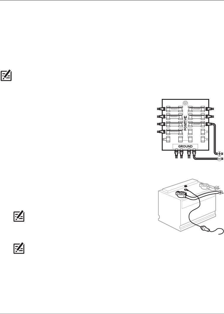
Fuse Terminal Connection
2a. Use crimp-on type electrical connectors (not included) that match
the terminal on the fuse panel. Attach the black wire to ground (–),
and the red wire to positive (+) 12 VDC or 24 VDC power. Install a 5
Amp fuse (not included) for protection of the unit.
OR
Battery Switch Connection
2b. Install the battery switch (not included) using the instructions
provided with it. You will also need to install an inline fuse holder
and a 5 Amp fuse (not included) for protection of the unit. Attach the
black wire to (–) ground, and the red wire to (+) 12 VDC or 24 VDC
power.
NOTE: The in-line fuse rating for the power cable is 5 Amp. The
thermal breaker rating is 3 Amp (if only connecting one device).
The suitable fuse rating for the thermal breaker is dependent on
the number of devices you connect.
NOTE: Humminbird recommends that best practice is observed in all vessel electrical installations,
as detailed in the following standards:
• BMEA Code of Practice for Electrical and Electronic Installations in Boats
• NMEA 0400 Installation Standard
• ABYC E-11 AC & DC Electrical Systems on Boats
• ABYC A-31 Battery chargers and Inverters
• ABYC TE-4 Lightning Protection
Fuse Terminal Connection
Battery Switch Connection
CHIRP_Radar_Install_Manual_532523-1EN_A.qxp_Layout 1 8/11/16 10:48 AM Page 19
3. Connect to the Control Head
Refer to your control head installation guide for additional information and instructions about connecting
cables.
Connect to ONIX
1. Insert the data cable connector into the Ethernet port on the control head.
2. Hand-tighten the screw nut on the cable to secure the connection.
3. Confirm there is enough cable slack to allow for the control head to pivot through its full tilt range and for
connecting or disconnecting the cables.
Connect to HELIX
To connect the Radar scanner to a HELIX control head, a separate purchase AS EC QDE Ethernet Adapter
Cable is required.
1. Connect the data cable connector to the AS EC QDE adapter cable connector. Hand-tighten the screw nut
on the cable to secure the connection.
2. Insert the AS EC QDE adapter cable connector into the Ethernet port on the control head.
3. Confirm there is enough cable slack to allow for the control head to pivot through its full tilt range and for
connecting or disconnecting the cables.
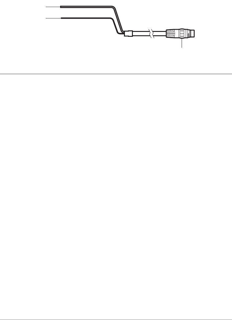
Radar Scanner Power Cable
red cable (positive)
black cable (negative)
cable connector
20
Connect to Power and Ethernet
Con
Use
insta
1.
2.
3.
4.
5.
CHIRP_Radar_Install_Manual_532523-1EN_A.qxp_Layout 1 8/11/16 10:48 AM Page 20

21 Connect to Power and Ethernet
ting
d for
pter
w nut
d for
Connect to an Ethernet Switch
Use the following instructions to connect the data cable to an Ethernet Switch. See the Ethernet Switch
installation guide for information about connecting cables.
1. Connect the data cable connector to an available port on the Ethernet Switch. Hand-tighten the screw nut
on the cable to secure the connection.
2. Connect an Ethernet cable to an available port on the Ethernet Switch.
3. Insert the Ethernet cable connector into the Ethernet port on the control head.
4. If the cable connector has a screw nut, hand-tighten the screw nut to secure the connection.
5. Confirm there is enough cable slack to allow for the control head to pivot through its full tilt range and for
connecting or disconnecting the cables.
NOTE: If the cables are too short for your application, extension cables are available. Visit our Web site at
humminbird.com.
CHIRP_Radar_Install_Manual_532523-1EN_A.qxp_Layout 1 8/11/16 10:48 AM Page 21

Tw
Reg
As y
keep
•
•
•
Hum
We
from
reta
or r
Hum
has
the
This
•
•
•
•
Plea
serv
THIS
ON T
ANY
DUR
HUM
ANY
Som
dam
state
22
7. Test the Installation
Perform the following tasks before using the product on the water:
• Mechanical checks
• Power on and initial setup
Mechanical Checks
Before powering on the product, perform the following mechanical checks:
1. Confirm that all securing bolts are fully tightened and the appropriate mechanical locking washers are in
place.
2. Confirm all connections are secure.
3. Confirm all connecting cables and wires are secured and protected as necessary.
Power On the Control Head
See your Humminbird operations manual to configure the radar and start transmission.
Test the Installation
CHIRP_Radar_Install_Manual_532523-1EN_A.qxp_Layout 1 8/11/16 10:48 AM Page 22

Two Year Limited Warranty & Service Policy
Registering Your Product
As you build your Humminbird network, it is important to register your control heads and accessories and
keep the software up to date.
• Go to humminbird.com and select My Humminbird to sign in or set up a new account.
•Software Updates: Under each registered product, click Downloads. Review the instructions in your
control head operations guide before proceeding with the update.
• Operations manuals for your control heads and accessories are available for download at
humminbird.com.
Humminbird 2 Year Limited Warranty
We warrant the original retail purchaser that products made by Humminbird have been manufactured free
from defects in materials and workmanship. This warranty is effective for two years from the date of original
retail purchase. Humminbird products found to be defective and covered by this warranty will be repaired
or replaced free of charge at Humminbird’s option and returned to the customer freight prepaid.
Humminbird’s sole responsibility under this warranty is limited to the repair or replacement of a product that
has been deemed defective by Humminbird. Humminbird is not responsible for charges connected with
the removal of such product or reinstallation of replaced or repaired parts.
This warranty does not apply to a product that has been:
• Improperly installed;
• Used in an installation other than that recom mended in the product installation and operation
instructions;
• Damaged or has failed because of an accident or abnormal operation;
• Repaired or modified by entities other than Humminbird.
Please retain your original receipt as a proof of the purchase date. This will be required for in-warranty
service.
THIS WARRANTY IS EXPRESSLY IN LIEU OF ANY OTHER WARRANTIES, OBLIGATIONS OR LIABILITIES
ON THE PART OF HUMMINBIRD AND WILL BE THE CUSTOMER’S EXCLUSIVE REMEDY, EXCEPT FOR
ANY APPLICABLE IMPLIED WARRANTIES UNDER STATE LAW WHICH ARE HEREBY LIMITED IN
DURATION TO TWO YEARS FROM THE DATE OF ORIGINAL PURCHASE. IN NO EVENT WILL
HUMMINBIRD BE LIABLE FOR ANY INCIDENTAL OR CONSEQUENTIAL DAMAGES FOR BREACH OF
ANY EXPRESS OR IMPLIED WARRANTY RELATING TO THE PRODUCTS.
Some states do not allow limitations on an implied warranty, or the exclusion of incidental or consequential
damages, so the above exclusions may not apply to you. You may also have other rights, which vary from
state to state
23 Warranty & Service Policy
re in
CHIRP_Radar_Install_Manual_532523-1EN_A.qxp_Layout 1 8/11/16 10:48 AM Page 23

Ret
Befo
Repa
Plea
the
Req
Auth
For
For
Humminbird Service Policy
Even though you’ll probably never need to take advantage of our incredible service policy, it’s good to know
that we back our products this confidently. We do it because you deserve the best. We will make every
effort to repair your unit within three business days from the receipt of your unit at our factory. This does
not include shipping time to and from our factory. Units received on Friday are typically shipped by the
following Wednesday, units received Monday are typically shipped by Thursday, etc.
All repair work is performed by factory-trained technicians to meet exacting factory specifications. Factory-
serviced units go through the same rigorous testing and quality control inspections as new production units.
After the original warranty period, a standard flat rate service charge will be assessed for each repair
(physical damage and missing parts are not included). Any repairs made after the original warranty will be
warranted for an additional 90 days after service has been performed by our factory technicians. You can
contact Humminbird Customer Service or visit our Web site to verify the flat rate repair fee for your product
(visit the Product Support section):
http://www.humminbird.com
We reserve the right to deem any product unserviceable when replacement parts are no longer available
or impossible to obtain. This Service Policy is valid in the United States only. This applies only to Humminbird
products returned to our factory in Eufaula, Alabama. This Service Policy is subject to change without notice.
DOMESTIC (USA) CUSTOMERS:
PLEASE DO NOT RETURN THIS PRODUCT TO THE STORE FOR SERVICE
For all technical issues please call 1-800-633-1468
or visit humminbird.com, click SUPPORT.
Please reference the product serial number and
model number when contacting Humminbird.
24
Warranty & Service Policy
CHIRP_Radar_Install_Manual_532523-1EN_A.qxp_Layout 1 8/11/16 10:48 AM Page 24

Returning your Unit for Service
Before sending your unit in for repair, please contact the factory, either by phone or by e-mail, to obtain a
Repair Authorization Number for your unit.
NOTE: Please do not return your Humminbird to the store for service.
Please have your product model name and serial number available before calling the factory. If you contact
the factory by e-mail, please include your product model name and serial number in the e-mail, and use
Request for Repair Authorization Number for your e-mail subject header. You should include your Repair
Authorization Number in all subsequent communications about your unit.
For IN-WARRANTY service, complete the following steps:
• Obtain a Repair Authorization Number from Humminbird Customer Service.
• Tag product with your name, street address, phone number, and your assigned Repair
Authorization Number.
• Include a brief written description of the problem.
• Include a copy of your receipt (to show proof and date of purchase).
• Return product freight prepaid to Humminbird, using an insured carrier with delivery confirmation.
For OUT-OF-WARRANTY service, complete the following steps:
• Obtain a Repair Authorization Number from Humminbird Customer Service.
• Include payment in the form of credit card number and expiration date, or a money order. Please
do not send cash.
• Tag product with your name, street address, phone number, and your assigned Repair
Authorization Number.
• Include a brief written description of the problem.
• Return product freight prepaid to Humminbird, using an insured carrier with delivery confirmation.
25 Warranty & Service Policy
now
very
does
the
tory-
nits.
pair
ll be
can
duct
able
bird
tice.
CHIRP_Radar_Install_Manual_532523-1EN_A.qxp_Layout 1 8/11/16 10:48 AM Page 25

Tro
Befo
revie
ther
No
•
•
•
•
•
•
Dis
Refe
Noi
If yo
Maintenance
Use the following procedures to ensure your Humminbird product continues to deliver top performance.
HIGH VOLTAGES WARNING! This product may contain high voltages. Do NOT remove any covers
or otherwise attempt to access internal components.
Recommended Yearly Maintenance Tasks
Clean the Hardware
1. Power off the Radar scanner.
2. Remove one of the bolts and associated washers.
3. Clean the bolt and washers.
4. Replace the bolt and washers.
5. Repeat steps 2 through 4 for all bolts.
6. Tighten all antenna-securing bolts to a torque of 11 ft·lbf (15 Nm).
Check the Cable Connections
1. Power off the Radar scanner.
2. Check that all connected cables are in good condition and securely attached.
3. Examine all cables for signs of chafing, cuts or other damage.
Check the Radar Scanner
1. Power off the Radar scanner.
2. Ensure the Radar scanner is firmly attached to the mounting surface.
Cleaning the Radar Scanner
The Radar scanner does not require regular cleaning. However, if you find it necessary to clean the unit,
please follow the steps below:
1. Power off the Radar scanner.
2. Wipe the unit clean with a damp cloth.
3. If necessary, use a mild detergent solution to remove grease marks.
Storage Requirements
Store upright, making sure you do not block the vents on the underside of the Radar scanner.
26
Maintenance
CHIRP_Radar_Install_Manual_532523-1EN_A.qxp_Layout 1 8/11/16 10:48 AM Page 26

Troubleshooting
Before contacting Humminbird Customer Service, please read the following section. Taking the time to
review these troubleshooting guidelines may allow you to solve a performance problem yourself, and
therefore avoid sending your unit back for repair.
No Connection to the Radar Scanner
• Check the cable connections. Confirm the adapter cable (if used) is connected at both ends and is
in good condition.
• Ensure the power supply thermal breaker has not tripped or fuse has not blown. If necessary, reset
breaker or replace fuse (one time only). If breaker keeps tripping or fuse keeps blowing, contact a
Humminbird authorized dealer for assistance.
• Ensure power supply maintains the correct voltage when the system is switched on.
• Ensure all products in the system have the correct software. Refer to your account at
humminbird.com for the latest software updates and the software update procedure for your
product.
• If the Radar scanner is connected to the control head via an Ethernet Switch, ensure that:
• All relevant equipment is correctly connected to the Ethernet Switch.
• The Ethernet Switch power supply is satisfactory.
• The Ethernet Switch is in good condition.
• Ethernet cables are securely connected and in good condition.
•Entire System Restart: Power off the control head and all connected equipment. Wait 10 seconds,
and then power on all equipment.
Displayed Bearing is Different to the True Bearing
Refer to the bearing alignment procedure detailed in your control head operations manual.
Noise
If you are experiencing noise or other interference, contact a NMEA approved technician for assistance.
27 Troubleshooting
ce.
overs
unit,
CHIRP_Radar_Install_Manual_532523-1EN_A.qxp_Layout 1 8/11/16 10:48 AM Page 27

Rec
IF B
Nois
Ant
Type
Peak
Tran
Bea
Pola
Rota
Specifications
Approvals
USA . . . . . . . . . . . . . . . . . . . . . . . . . . . . . . . . . . . . . . . . . 47CFR FCC Part 2 & Part 80 Certificate of Approval
Canada . . . . . . . . . . . . . . . . . . . . . . . . . . . . . . . . . . . . . . . . . RSS238 Iss. 1 Technical Acceptance Certificate
European Union & EFTA . . . . . . . . . . . . . . . . . . . . . . . R & TTE Directive 1999/05/EC Certificate of Opinion
Australia & New Zealand . . . . . . . . . . . . . . . . . . . . . ACMA Declaration of Conformity Compliance level 3
General
Voltage Supply . . . . . . . . . . . . . . . . . . . . . . . . . . . 12 or 24 VDC (minimum: 10.8 VDC, maximum: 31.2 VDC)
Power Consumption . . . . . . . . . . . . . . . . . . . . . . . . . . . . . . . . . . . . . . . . Transmit Mode (maximum): 17 W
Standby Mode: 7 W
Operating Temperature Range . . . . . . . . . . . . . . . . . . . . . . . . . . . . . . . . . . . . . 14 to 131° F (-10 to + 55° C)
Storage Temperature Range . . . . . . . . . . . . . . . . . . . . . . . . . . . . . . . . . . . . . . -13 to 158° F (-25 to + 70° C)
Wind Force . . . . . . . . . . . . . . . . . . . . . . . . . . . . . . . . . . . . . . . . . . . . . . up to 95% at 95° F (35° C) 100 Knots
Range Scales . . . . . . . . . . . . 1/16, 1/8, 1/4, 3/8, 1/2, 3/4, 1, 1.5, 2, 3, 4, 6, 8, 12, 16, and 24 nautical miles
Water Resistance . . . . . . . . . . . . . . . . . . . . . . . . . . . . . . . . . . . . . . . . . . . . . . . . . . . . . . . . . . . IPX6 (IEC 529)
Weight . . . . . . . . . . . . . . . . . . . . . . . . . . . . . . . . . . . . . . . . . . . . . . . . . . . . . . . . . . . . . . . 12.3 pounds (5.6 kg)
Power Cable Length . . . . . . . . . . . . . . . . . . . . . . . . . . . . . . . . . . . . . . . . . . . . . . . . . . . . . . . 32.8 feet (10 m)
Transmitter
Type . . . . . . . . . . . . . . . . . . . . . . . . . . . . X-band solid-state transmitter with pulse compression technology
Transmit Frequency . . . . . . . . . . . . . . . . . . . . . . . . . . . . . . . . . . . . . . . . . . . . . . . . . . . . . . 9354 to 9446 MHz
Peak Power Output . . . . . . . . . . . . . . . . . . . . . . . . . . . . . . . . . . . . . . . . . . . . . . . . . . . . . . . . . . . . . . . . . 20 W
Duplexer . . . . . . . . . . . . . . . . . . . . . . . . . . . . . . . . . . . . . . . . . . . . . . . . . . . . . . . . . . . . . . . . . . . . . . Circulator
Pulse Widths (3 dB) . . . . . . . . . . . . . . . . . . . . . . . . . . . . . . . . . . . . . . . . . . . . . . . . . . . . . . . . 40 ns to 14.7
μ
s
CHIRP Lengths . . . . . . . . . . . . . . . . . . . . . . . . . . . . . . . . . . . . . . . . . . . . . . . . . . . . . . . . . . . . 400 ns to 22
μ
s
Pulse Repetition Frequency . . . . . . . . . . . . . . . . . . . . . . . . . . . . . . . . . . . . . . . . . . . . . . 2083 Hz to 4167 Hz
CHIRP Bandwidth . . . . . . . . . . . . . . . . . . . . . . . . . . . . . . . . . . . . . . . . . . . . . . . . . . . . . . . . . . . Up to 32 MHz
Standby Mode . . . . . . . . . . . . . . . . . . . . . . . . . . . . . . . . . . . . . . . . . . . . . . . . . . . . . . . Scanner rotation - OFF
Scanner transmission - OFF
28
Specifications
CHIRP_Radar_Install_Manual_532523-1EN_A.qxp_Layout 1 8/11/16 10:48 AM Page 28

Receiver
IF Bandwidth . . . . . . . . . . . . . . . . . . . . . . . . . . . . . . . . . . . . . . . . . . . . . . . . . . . . . . . . . . . . . . . . . . . . 26 MHz
Noise Figure . . . . . . . . . . . . . . . . . . . . . . . . . . . . . . . . . . . . . . . . . . . . . . . . . . . . . . . . . . . . . . . . 4.0 dB or less
Antenna
Type . . . . . . . . . . . . . . . . . . . . . . . . . . . . . . . . . . . . . . . . . . . . . . . . . . . . . . . . . . . . . . . . . . . . . . . . Patch Array
Peak Power Output . . . . . . . . . . . . . . . . . . . . . . . . . . . . . . . . . . . . . . . . . . . . . . . . . . . . . . . . . . . . . . . . . 20 W
Transmit Frequency . . . . . . . . . . . . . . . . . . . . . . . . . . . . . . . . . . . . . . . . . . . . . . . . . . . . . . 9354 to 9446 MHz
Beamwidth (nominal) . . . . . . . . . . . . . . . . . . . . . . . . . . . . . . . . . . . . . . . . . . . . . . . . . . . . . . Horizontal: 4.9°
Vertical: 20°
Polarization . . . . . . . . . . . . . . . . . . . . . . . . . . . . . . . . . . . . . . . . . . . . . . . . . . . . . . . . . . . . . . . . . . . Horizontal
Rotation Speed . . . . . . . . . . . . . . . . . . . . . . . . . . . . . . . . . . . . . . . . . . . . . . . . . . . . . . . . . . . . 24 rpm nominal
NOTE: Product specifications and features are subject to change without notice.
29 Specifications
oval
cate
nion
vel 3
VDC)
7 W
7 W
° C)
° C)
nots
miles
529)
6 kg)
0 m)
ogy
MHz
0 W
ator
7
μ
s
2
μ
s
7 Hz
MHz
OFF
OFF
CHIRP_Radar_Install_Manual_532523-1EN_A.qxp_Layout 1 8/11/16 10:48 AM Page 29
Radar Scanner Dimensions
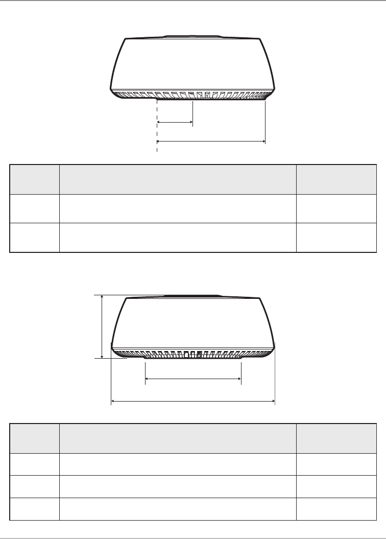
Radar Scanner Dimensions - Side View
A
B
Dimension Description Measurement
ADistance from the centerline of the Radar scanner to the front
of the mounting base. 4.57 in (116 mm)
BDistance from the rear of the mounting base to the front of the
mounting base. 13.95 in (355 mm)
Radar Scanner Dimensions - Rear View
C
D
E
Dimension Description Measurement
CHeight of Radar scanner. 8.25 in (209.5 mm)
DMounting base width (rear of unit). 12.58 in (319.5 mm)
EWidth of Radar scanner. 21.30 in (541 mm)
30
Specifications
CHIRP_Radar_Install_Manual_532523-1EN_A.qxp_Layout 1 8/11/16 10:48 AM Page 30
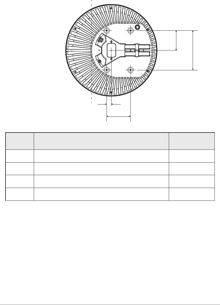
Radar Scanner Dimensions - Underside View
F
G
H
I
Dimension Description Measurement
FDistance from the centerline to the rear mounting hole. 4.59 in (116.5 mm)
GDistance between mounting holes. 9.17 in (233 mm)
HDistance from the centerline to the front mounting hole. 1.08 in (27.5 mm)
IDistance between front and rear mounting holes. 5.57 in (141.5 mm)
31 Specifications
CHIRP_Radar_Install_Manual_532523-1EN_A.qxp_Layout 1 8/11/16 10:48 AM Page 31
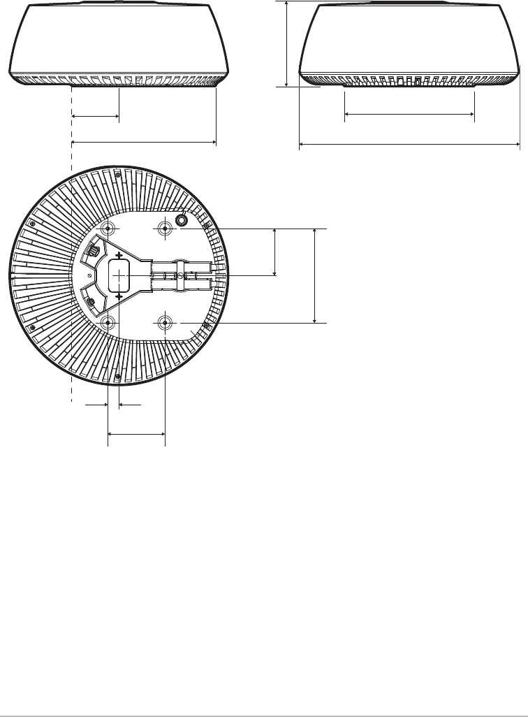
No
Radar Scanner Dimensions
4.57 in
(116 mm)
13.98 in (355 mm)
8.25 in
(209.5 mm)
12.58 in (319.5 mm)
21.3 in (541 mm)
4.59 in
(116.5 mm)
9.17 in
(233 mm)
1.08 in
(27.5 mm)
5.57 in
(141.5 mm)
32
Specifications
CHIRP_Radar_Install_Manual_532523-1EN_A.qxp_Layout 1 8/11/16 10:48 AM Page 32

Notes
33
CHIRP_Radar_Install_Manual_532523-1EN_A.qxp_Layout 1 8/11/16 10:48 AM Page 33

Contact Humminbird
Contact Humminbird Customer Service in any of the following ways:
Web site:
humminbird.com
E-mail:
service@humminbird.com
Telephone:
1-800-633-1468
Direct Shipping:
Humminbird
Service Department
678 Humminbird Lane
Eufaula, AL 36027 USA
Hours of Operation:
Monday - Friday
8:00 a.m. to 4:30 p.m. (Central Standard Time)
34
Contact Humminbird
CHIRP_Radar_Install_Manual_532523-1EN_A.qxp_Layout 1 8/11/16 10:48 AM Page 34