Flir BelgiumBA RAY54 VHF/FM marine transceiver with class D DSC User Manual 81231 1
Raymarine UK Ltd. VHF/FM marine transceiver with class D DSC 81231 1
Contents
- 1. Owner handbook 1
- 2. Owner handbook 2
- 3. Owner handbook 3
Owner handbook 3
Chapter 6: Menu Settings 73
Chapter 6: Menu Settings
6.1 Menu Function
The radio’s setup functions are accessed through the Menu mode. Menu
mode selections are as follows.
Item Description
PHONEBOOK A list of frequently-called DSC stations that you can select for making an
individual call. Up to 20 Phonebook entries can be stored.
LOCAL/DIST LOCAL mode eliminates noise, but degrades receiver sensitivity.
DISTANT mode enables normal receiver sensitivity.
BACKLIGHTING Selects the backlight levels for the LCD, base station keypad and micro-
phone keypad.
CONTRAST Selects the LCD contrast setting.
GPS/TIME Used to manually set latitude/longitude position and UTC time for a DSC
distress message. Also selects how the data is displayed on the LCD.
RADIO SETUP Selects four separate radio settings:
a) BAND – Frequency Group (US, International, Canadian)
b) CH NAME – Descriptive name for each channel (up to 11 characters)
c) RING VOLUME – Alarm tone volume (LOUD or SOFT)
d) KEY BEEP – Key beep volume (LOUD, SOFT or OFF)
DSC SETUP Selects the following DSC settings:
a) MY MMSI ID – Used for one-time entry of the MMSI number required for
DSC functions. If already programmed, displays the
saved MMSI ID number.
b) GROUP SETUP – Stores up to 3 Group MMSI IDs and associated Names
c) POS REPLY – Selects how Position Request data is transmitted
d) AUTO CH CHG – Selects whether your radio automatically switches to
the requested working channel when DSC Calls are
received.
RESET Enables a return to factory default settings.
81231_1.book Page 73 Thursday, April 22, 2004 5:21 PM
74 Ray54 VHF Radio
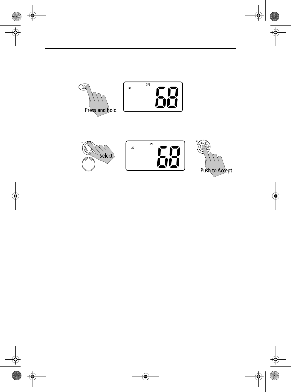
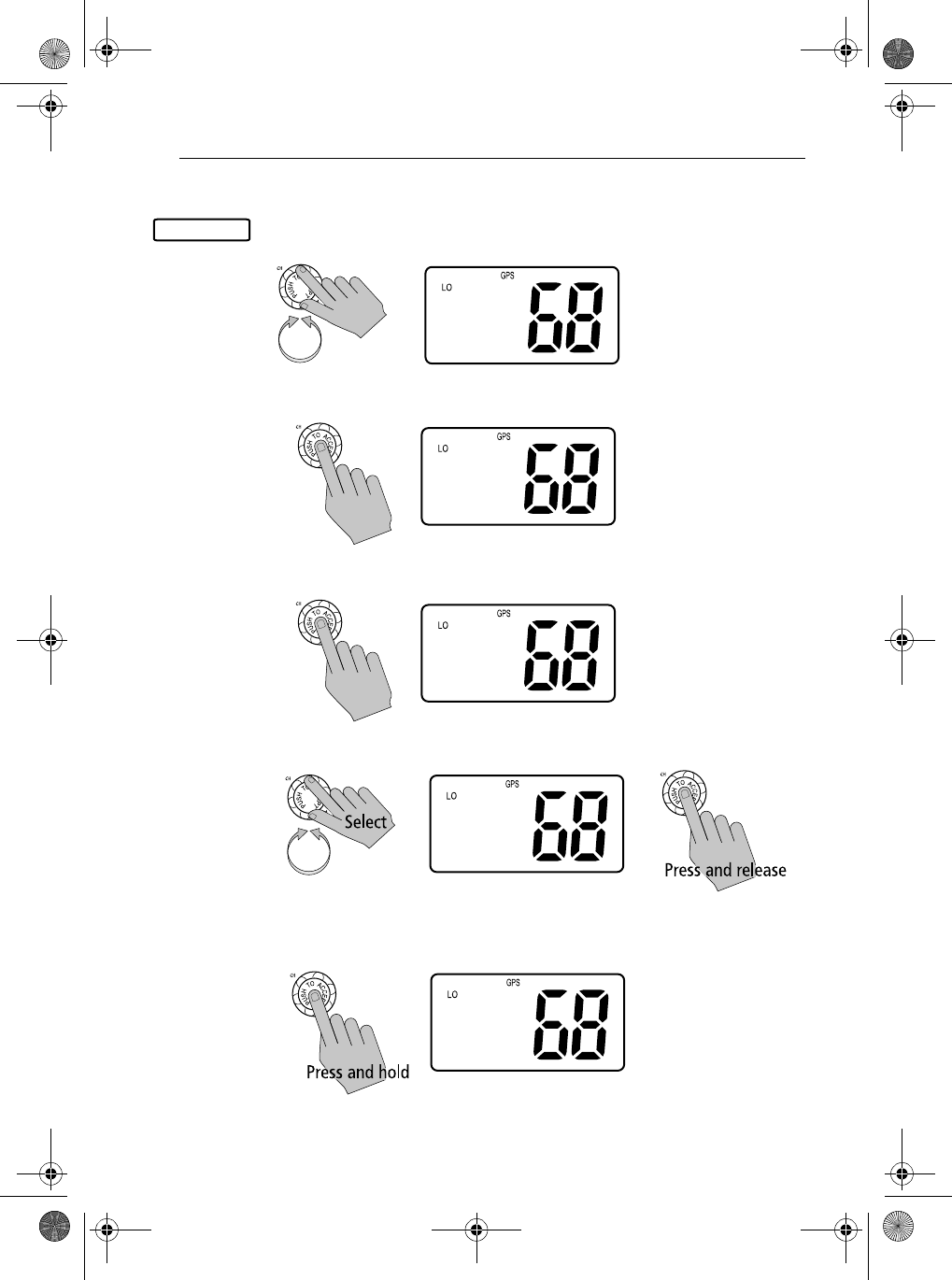
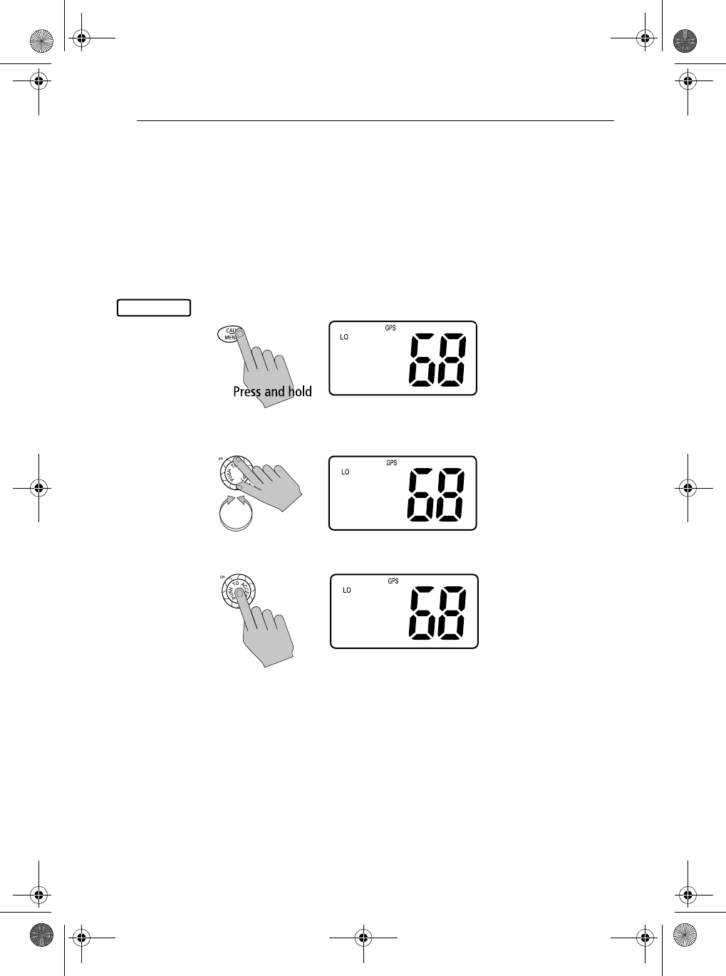
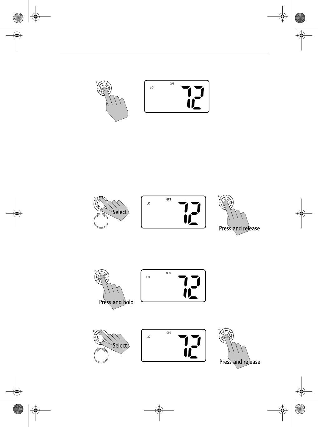
➤To access the Menu Mode:
1. Press and hold the CALL/MENU key to enter menu mode. The list of
available functions appear on the dot matrix display.
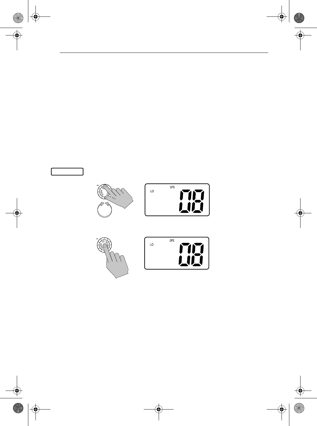
2. Rotate the CH knob to scroll down the list until the arrow points to the
desired function. Push the CH knob to accept.
To exit the Menu mode or sub-mode, press the 16/9 or CLEAR/WX keys, or
else select the EXIT option from the menu.
>PHONEBOOK
LOCAL/DIST
BACKLIGHT
CONTRAST
>RADIO SETUP
DSC SETUP
RESET
EXIT
81231_1.book Page 74 Thursday, April 22, 2004 5:21 PM
Chapter 6: Menu Settings 75
6.2 DSC Phonebook
The Phonebook stores up to 20 preprogrammed MMSI numbers that you can
select for making an individual call. The numbers are stored by name and
contain the station’s MMSI number. You can add, edit and delete entries from
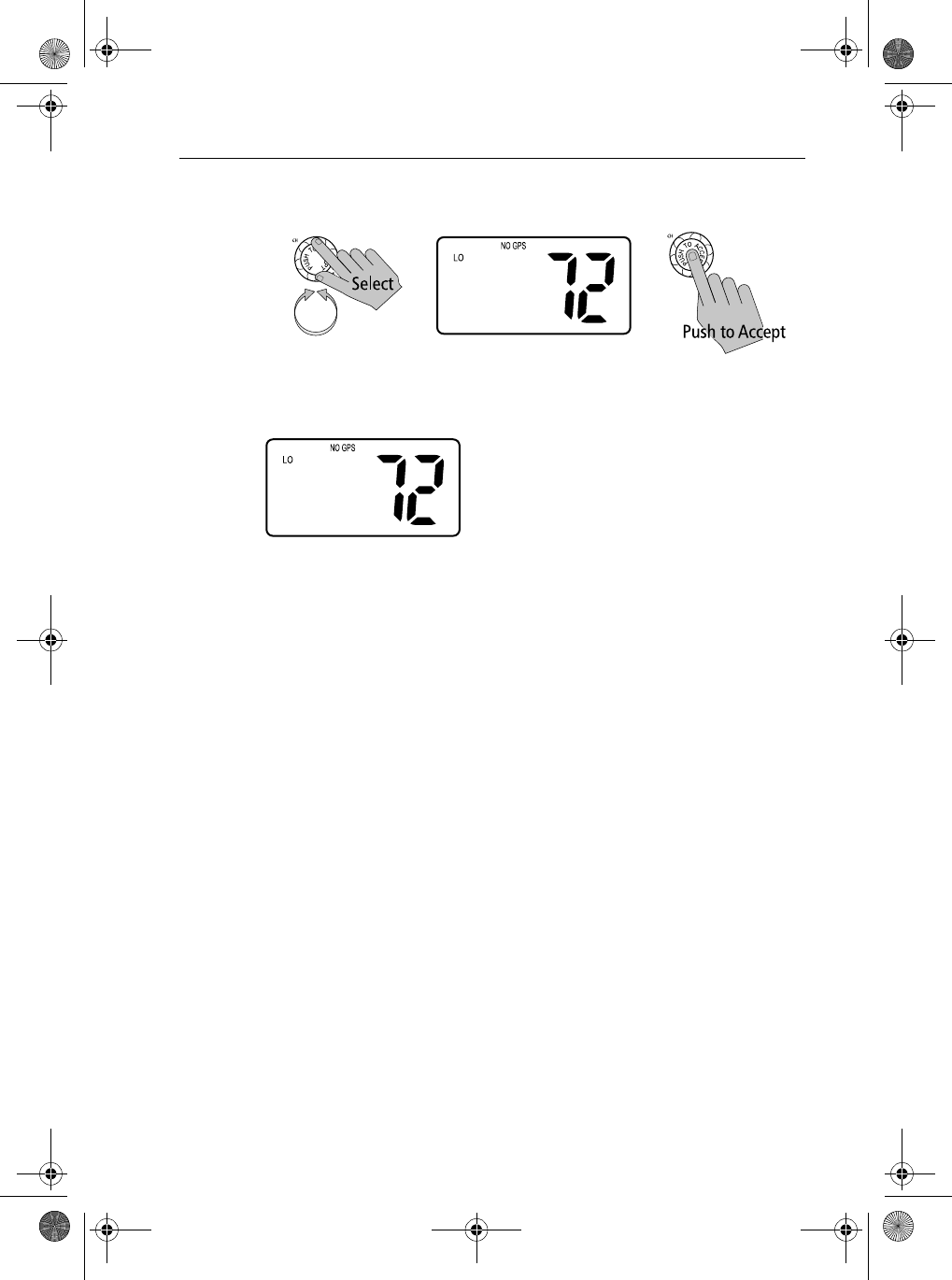
the Phonebook, much as you would on a cellular telephone. Rotate the CH
knob to make an item appear on the dot matrix display and then press in the
CH knob to select that item.
Note: The following examples demonstrate making calls to other ships. You
may also make DSC calls to shore stations. Shore MMSI numbers start with
“00”.
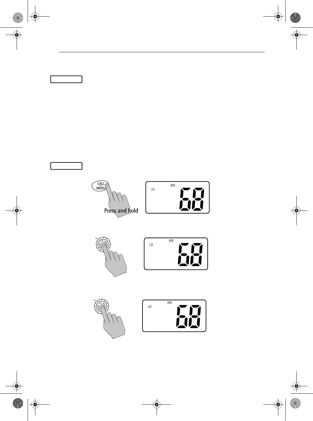
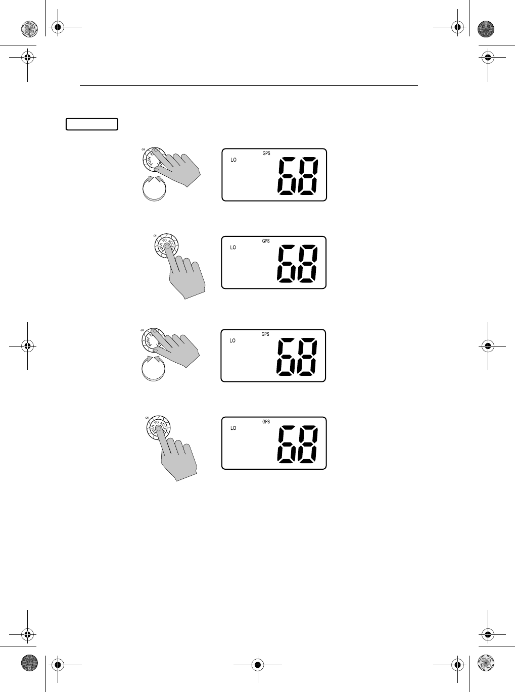
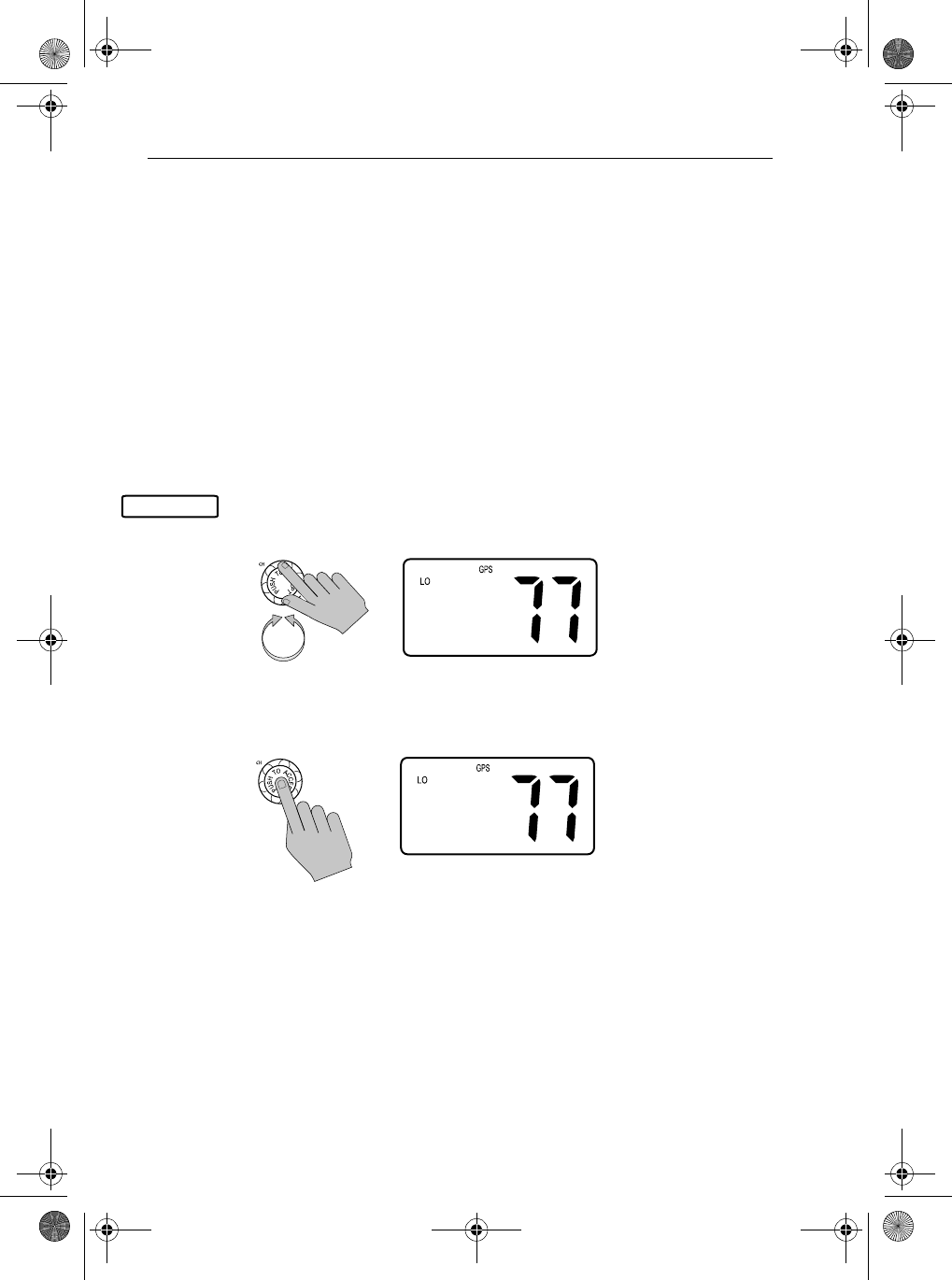
Adding an Entry
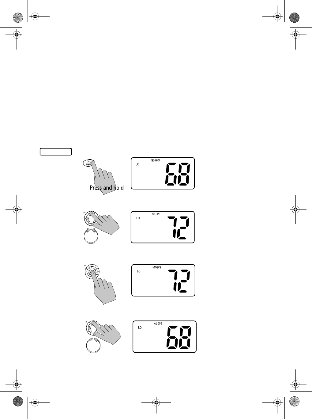
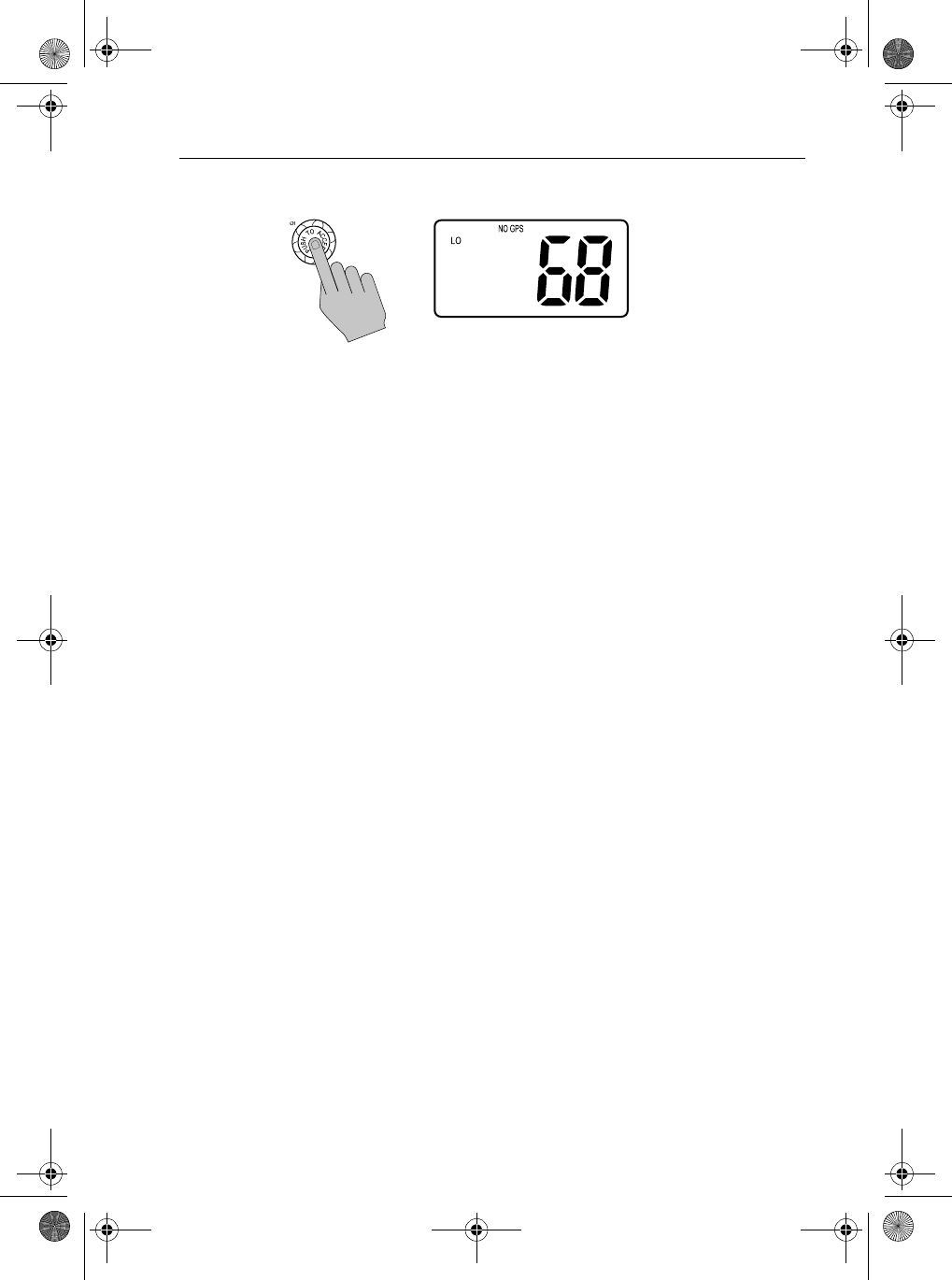
1. Press and hold the CALL/MENU knob. The Menu screen appears on the
dot matrix display.
2. Press the CH knob to select Phonebook. The Phonebook screen appears.
3. Press and release the CH knob to select <NEW ENTRY>.
PHONEBOOK
PHONEBOOK
>PHONEBOOK
LOCAL/DIST
BACKLIGHT
CONTRAST
><NEW ENTRY>
CALL ME AL
FINTASTIC
OCEANEER
ENTER NAME:
____________
ENTER MMSI:
_________
81231_1.book Page 75 Thursday, April 22, 2004 5:21 PM
76 Ray54 VHF Radio
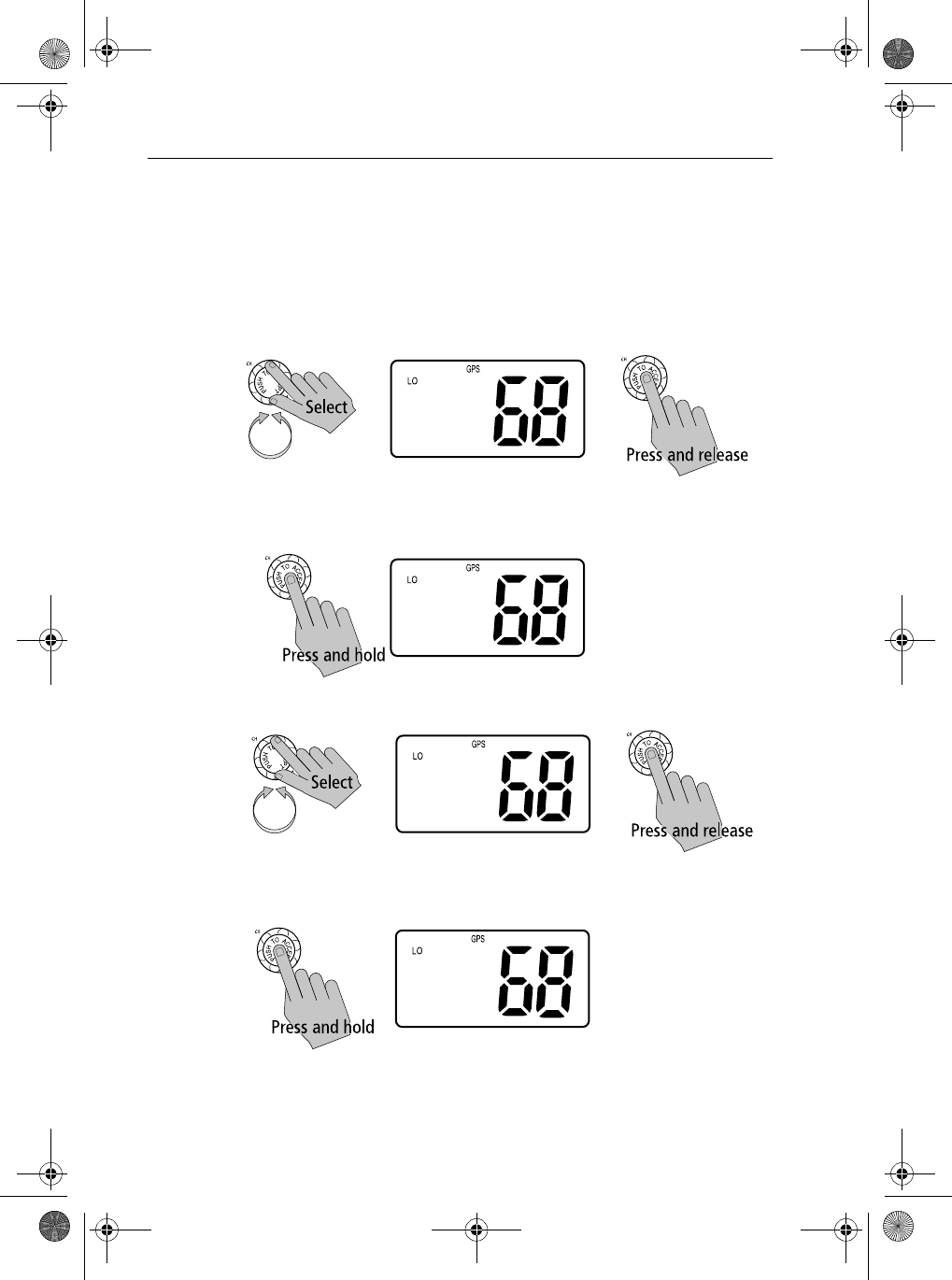
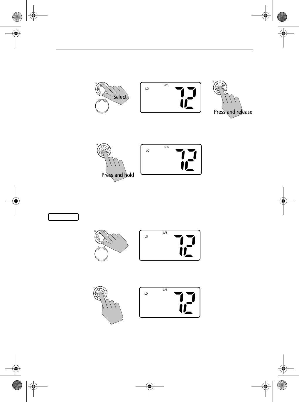
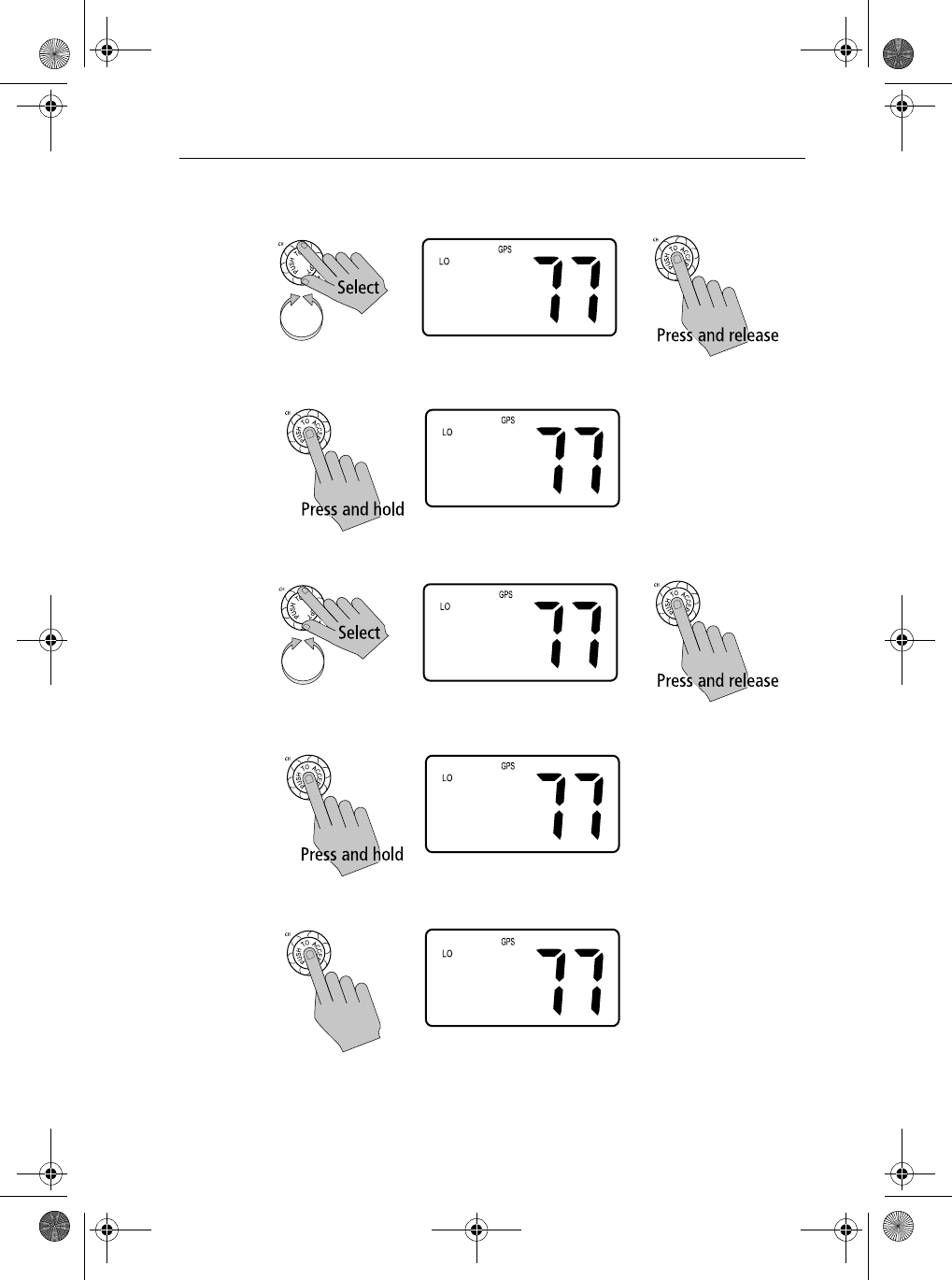
4. Rotate the CH knob to scroll through values for the first character in the
NAME field.
All alpha and numeric characters are available. The first available char-
acter is a blank (space). The final available character is an arrow, which
serves as a backspace. A total of 12 character spaces are available.
When the desired character appears, press and release the CH knob to
accept it. The next position is ready to be selected.
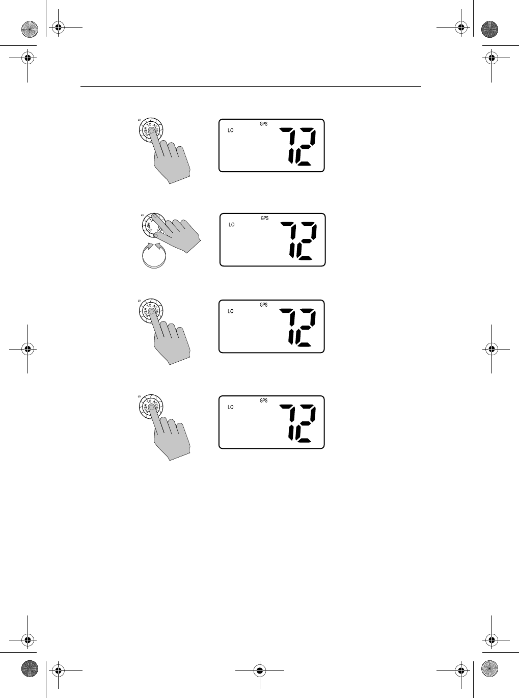
5. Continue this process until all NAME characters are selected. Press and
hold the CH knob to accept the name and move on to the MMSI ID.
6. Use same procedure to enter the MMSI characters.
7. When all characters have been selected, press and hold the CH knob to
accept. The new entry appears in the Phonebook.
ENTER NAME:
B___________
ENTER MMSI:
_________
ENTER NAME:
BAHAMA MAMA_
ENTER MMSI:
_________
ENTER NAME:
BAHAMA MAMA
ENTER MMSI:
8669823__
<NEW ENTRY>
>BAHAMA MAMA
CALL ME AL
FINTASTIC
81231_1.book Page 76 Thursday, April 22, 2004 5:21 PM
Chapter 6: Menu Settings 77
Editing an Existing Entry
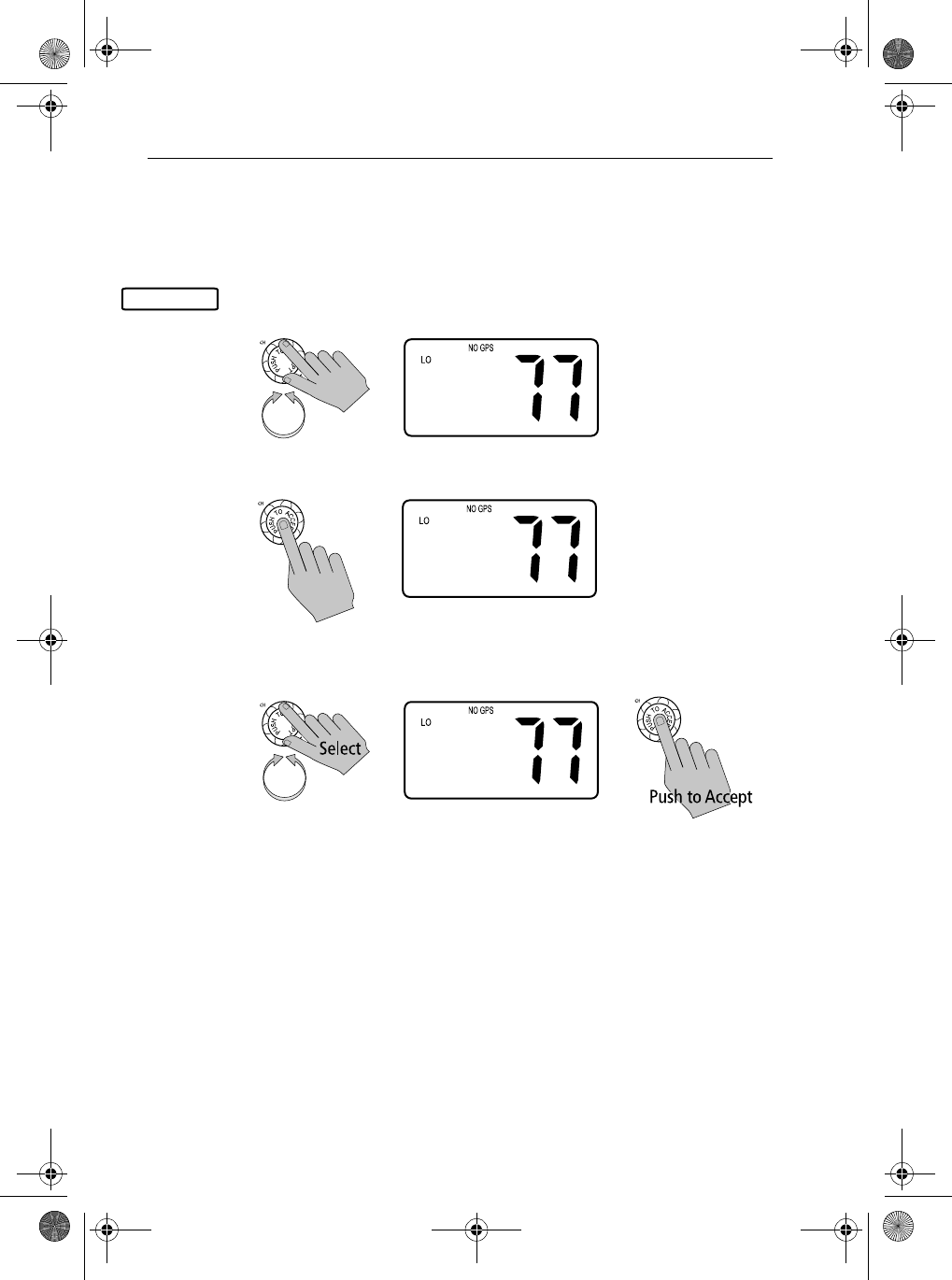
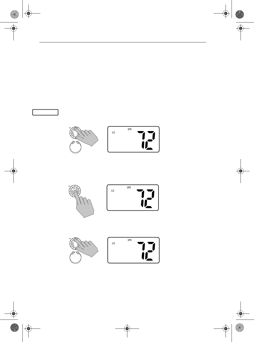
1. From the Phonebook, rotate the CH knob until the arrow on the dot matrix
display points to entry you wish to edit.
2. Push in the CH knob to select the name.
3. Push the CH knob again to select EDIT.
4. Make your changes, using the CH knob.
5. When finished, press and hold the CH knob to accept. The revised name
appears in the list.
PHONEBOOK
<NEW ENTRY>
FINTASTIC
>OCEANEER
SLIM JIM
ID523556232
>EDIT
DELETE
EXIT
NAME:
OCEANEER
MMSI ID:
ID523556232
NAME:
OCEAN_ER
MMSI ID:
ID523556232
<NEW ENTRY>
FINTASTIC
>OCEAN EAR
SLIM JIM
81231_1.book Page 77 Thursday, April 22, 2004 5:21 PM
78 Ray54 VHF Radio
Deleting an Existing Entry
1. From the Phonebook, rotate the CH knob until the arrow on the dot matrix
display points to entry you wish to delete.
2. Push the CH knob to select the name.
3. Rotate the CH knob until the arrow is pointing to DELETE.
4. Push the CH knob. The entry is removed.
6.3 Local / Distant
This mode toggles between full receiver sensitivity (Distant mode) and
attenuated receiver sensitivity (Local mode). Local mode is used is used to
decrease unwanted reception (noise). Local Mode is commonly used in areas
where interference, usually from shore based paging systems, is high.
PHONEBOOK
<NEW ENTRY>
FINTASTIC
>OCEAN EAR
SLIM JIM
ID523556232
>EDIT
DELETE
EXIT
ID523556232
EDIT
>DELETE
EXIT
><NEW ENTRY>
CALL ME AL
FINTASTIC
SLIM JIM
81231_1.book Page 78 Thursday, April 22, 2004 5:21 PM
Chapter 6: Menu Settings 79
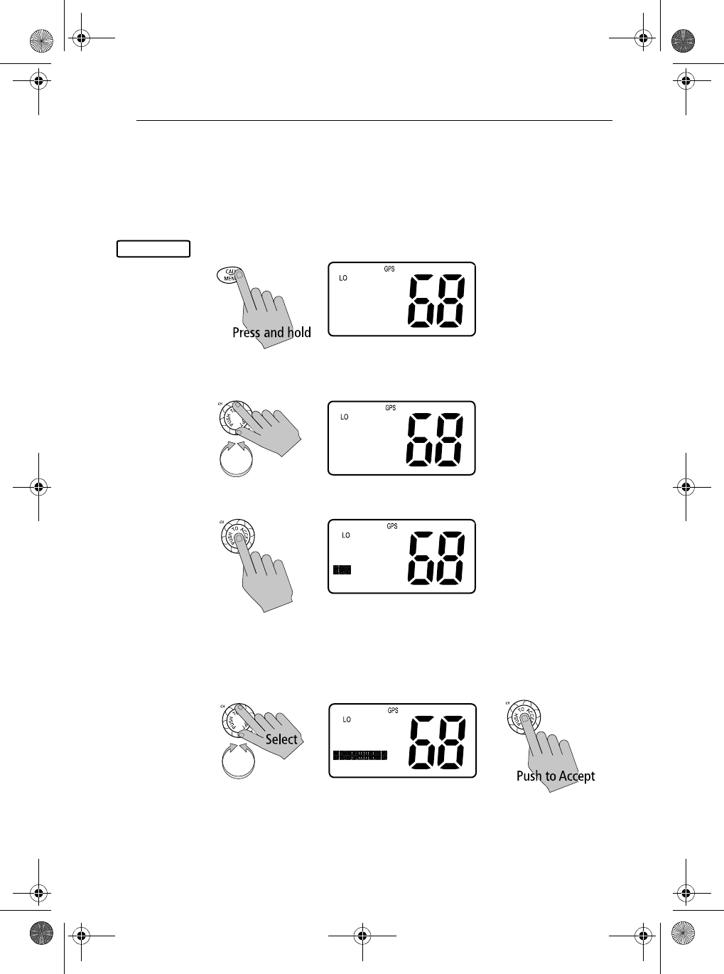
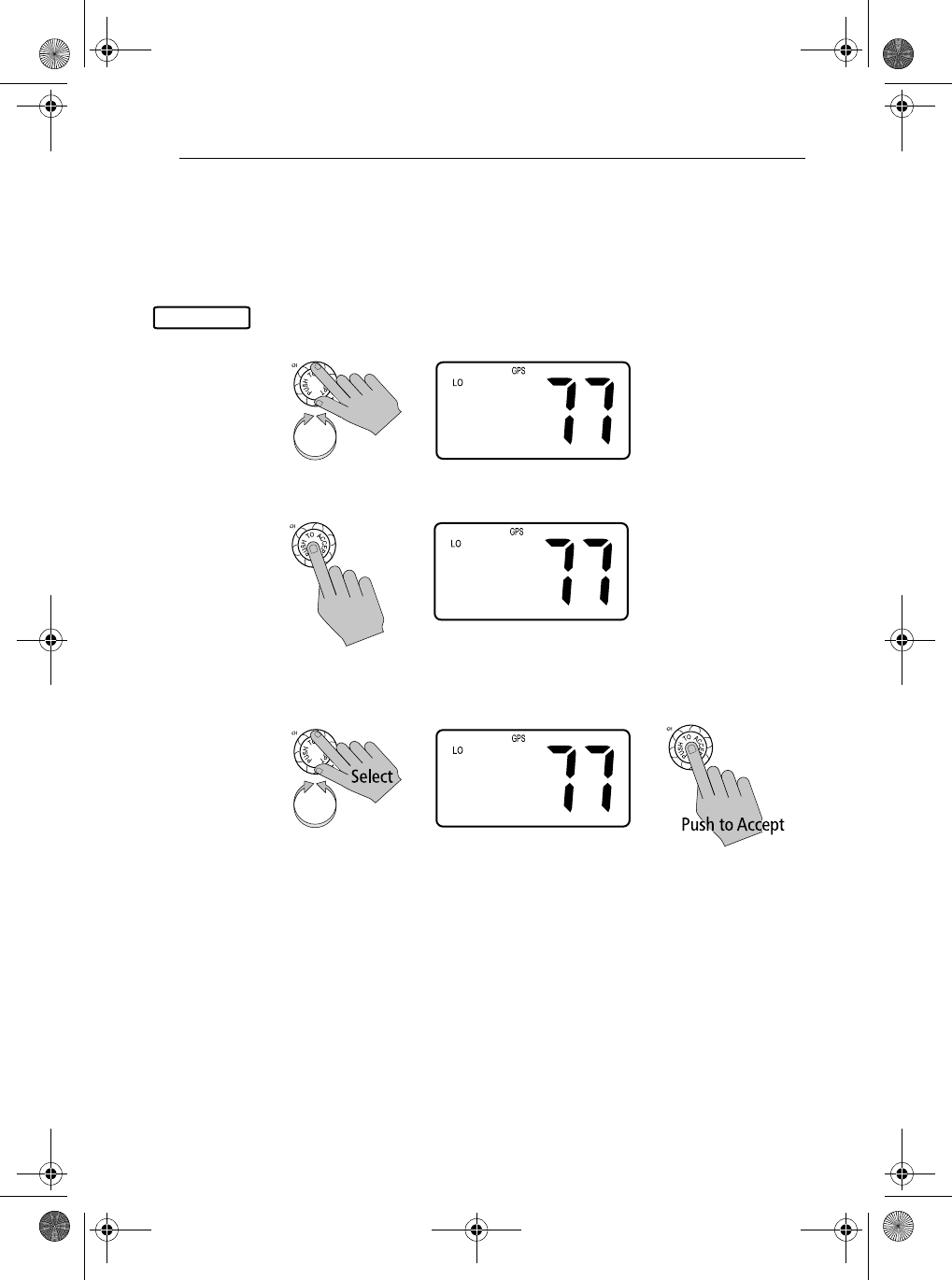
➤To select the sensitivity setting:
1. Press and hold the CALL/MENU key to enter Menu mode.
2. Rotate the CH knob to scroll down the list until the arrow points to LOCAL/
DIST.
3. Push the CH knob to accept. The LOCAL/DIST screen appears.
4. Rotate the CH knob until the arrow points to the desired mode: LOCAL or
DISTANT. Push the CH knob to accept. While in local mode, the LOCAL
indicator appears in the LCD display.
To exit this sub-mode, press the 16/9 or CLEAR/WX keys, or else select the
BACK option from the menu.
LOCAL/DIST
>PHONEBOOK
LOCAL/DIST
BACKLIGHT
CONTRAST
>LOCAL/DIST
BACKLIGHT
CONTRAST
GPS/TIME
>DISTANT
LOCAL
BACK
DISTANT
>LOCAL
BACK
81231_1.book Page 79 Thursday, April 22, 2004 5:21 PM
80 Ray54 VHF Radio
6.4 Backlight Adjustment
This setting adjusts the backlight brightness of the LCD, microphone keypad
and base station keypad.
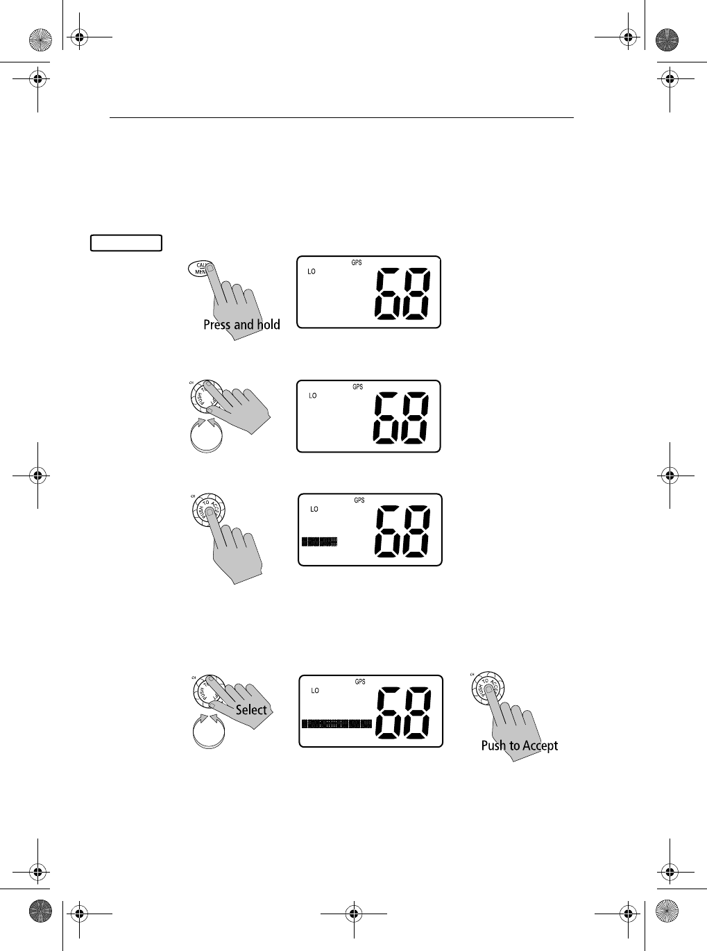
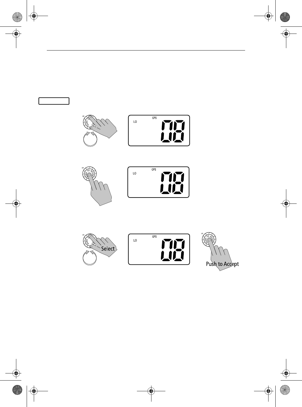
➤To adjust the backlight setting:
1. Press and hold the CALL/MENU key to enter Menu mode.
2. Rotate the CH knob until the arrow points to BACKLIGHT.
3. Push the CH knob to accept. The Backlight screen appears.
4. Rotate the CH knob to select the desired backlight level. The number of
blocks illuminated on line 3 of the dot matrix display indicate the level:
For HI all blocks are illuminated; for LOW only half are illuminated; for
OFF none are illuminated. Push the CH knob to accept.
The Distress key backlighting is never turned OFF. When the selection is
made the radio returns to the previous Menu Selection.
To exit this sub-mode, press the 16/9 or CLEAR/WX keys.
BACKLIGHT
>PHONEBOOK
LOCAL/DIST
BACKLIGHT
CONTRAST
>BACKLIGHT
CONTRAST
GPS/TIME
RADIO SETUP
BACKLIGHT
OFF HI
PRESS ACCEPT
BACKLIGHT
OFF HI
PRESS ACCEPT
81231_1.book Page 80 Thursday, April 22, 2004 5:21 PM
Chapter 6: Menu Settings 81
6.5 Contrast Adjustment
This setting adjusts the four levels of LCD contrast. A larger number of
blocks indicate a darker LCD.
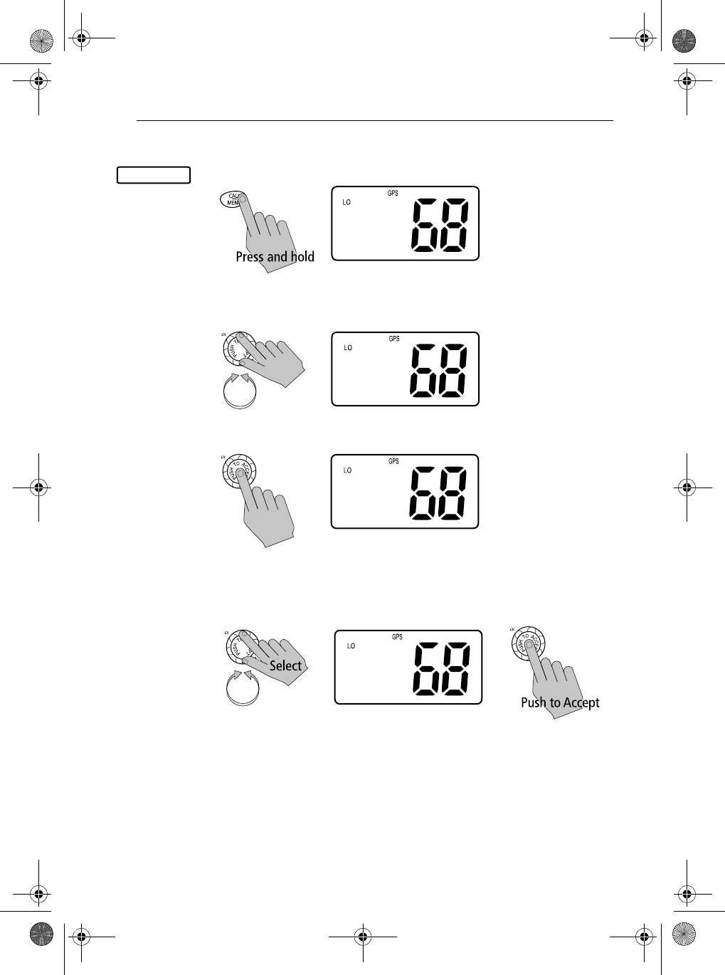
➤To adjust the contrast setting:
1. Press and hold the CALL/MENU key to enter Menu mode.
2. Rotate the CH knob to scroll down the list until the arrow points to CON-
TRAST.
3. Push the CH knob to accept. The Contrast screen appears.
4. Rotate the CH knob to select the desired contrast level. The number of
blocks illuminated on line 3 of the dot matrix display indicate the level:
For HI all blocks are illuminated; for LO none are illuminated. Push the CH
knob to accept your selection.
When the selection is made the radio returns to the previous Menu Selection.
To exit this sub-mode, press the 16/9 or CLEAR/WX keys.
CONTRAST
>PHONEBOOK
LOCAL/DIST
BACKLIGHT
CONTRAST
>CONTRAST
GPS/TIME
RADIO SETUP
DSC SETUP
CONTRAST
LO HI
PRESS ACCEPT
CONTRAST
LO HI
PRESS ACCEPT
81231_1.book Page 81 Thursday, April 22, 2004 5:21 PM
82 Ray54 VHF Radio
6.6 GPS/Time Setup
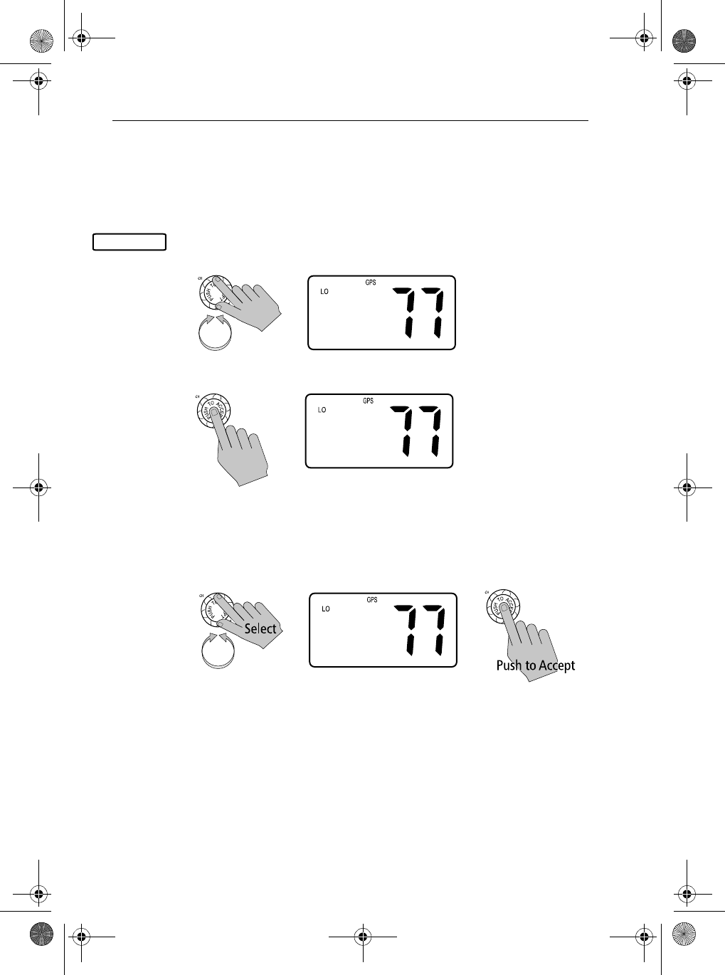
By default, the Ray54 auto-detects NMEA strings and decodes appropriate
latitude/longitude position and time. If the GPS navigation receiver is not
connected on or is not functional, a manual latitude/longitude position and
UTC time can be entered and used in the DSC distress transmitted message.
When valid Lat/Lon information is detected, the GPS icon is displayed on the
LCD. When there is no valid position information, NO GPS appears.
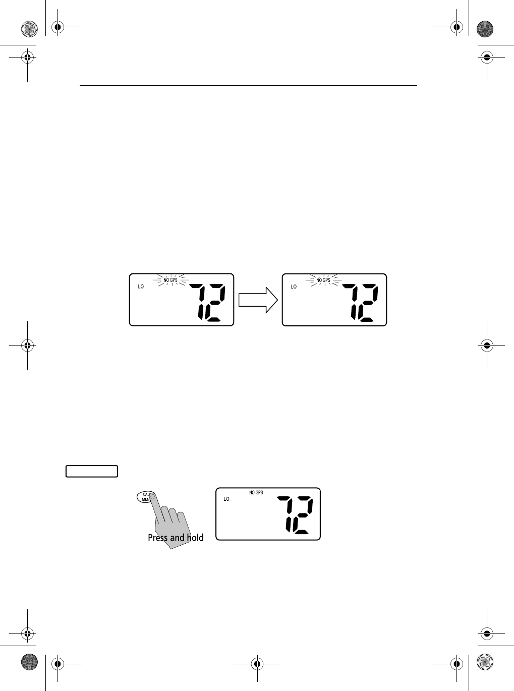
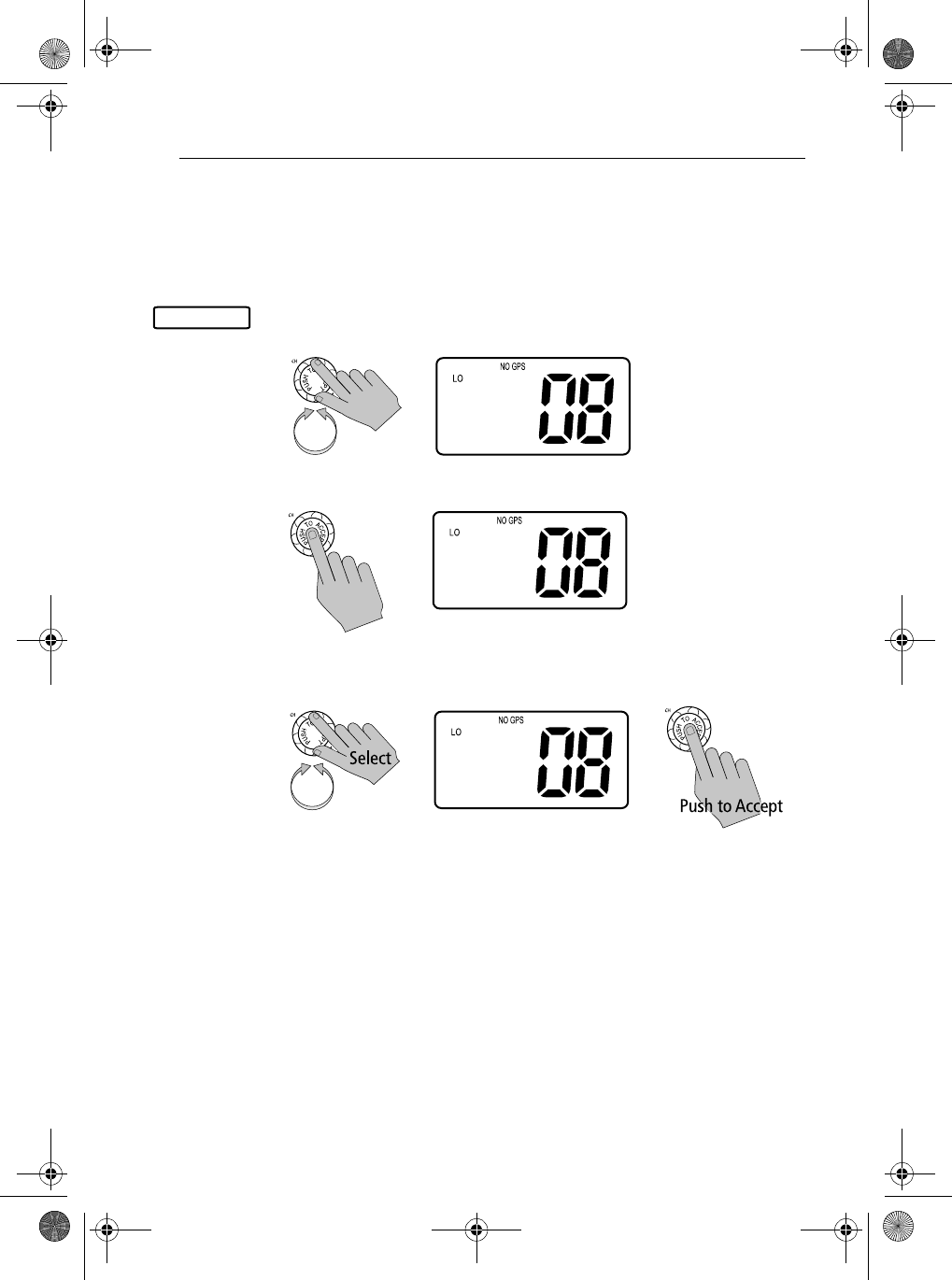
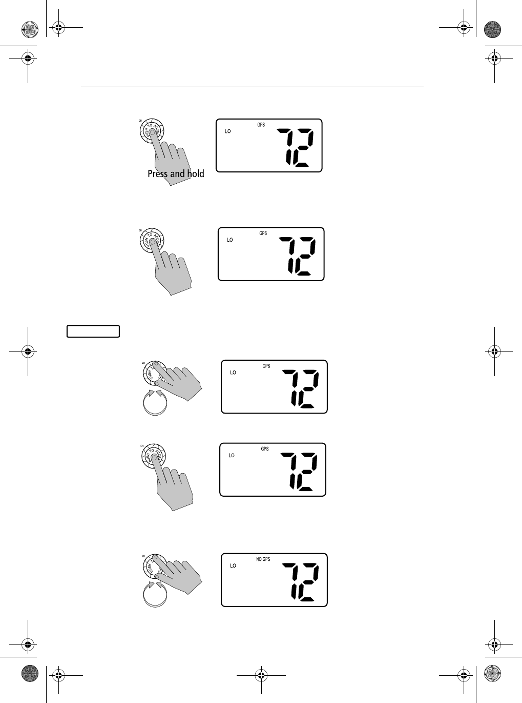
When GPS Information Not Available
If no GPS data is available, the NO GPS icon appears, POS DATA REQ is
displayed on the dot matrix display, followed by NO POS DATA. An alarm
sounds for 5 seconds or until you acknowledge by pressing any key.
The position (lat/lon) fields are set to all 9’s and time field is set to all 8’s. The
alert repeats every four hours as long as no position information has been
entered manually.
If position data is entered manually but has not been updated during the
previous 23.5 hours, all the position fields are set to 9’s and the display reverts
to NO POS DATA.
Note: The Manual Lat/Lon function is valid only when your radio is not con-
nected to a GPS receiver.
➤To manually set the GPS position and time settings:
1. Press and hold the CALL/MENU key to enter Menu mode.
SHIP TO SHIP
POS DATA REQ
SHIP TO SHIP
NO POS DATA
GPS/TIME
>PHONEBOOK
LOCAL/DIST
BACKLIGHT
CONTRAST
81231_1.book Page 82 Thursday, April 22, 2004 5:21 PM
Chapter 6: Menu Settings 83
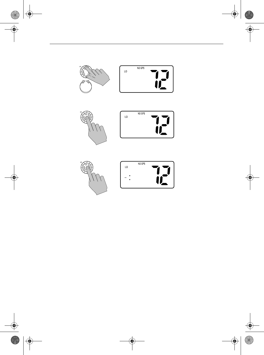
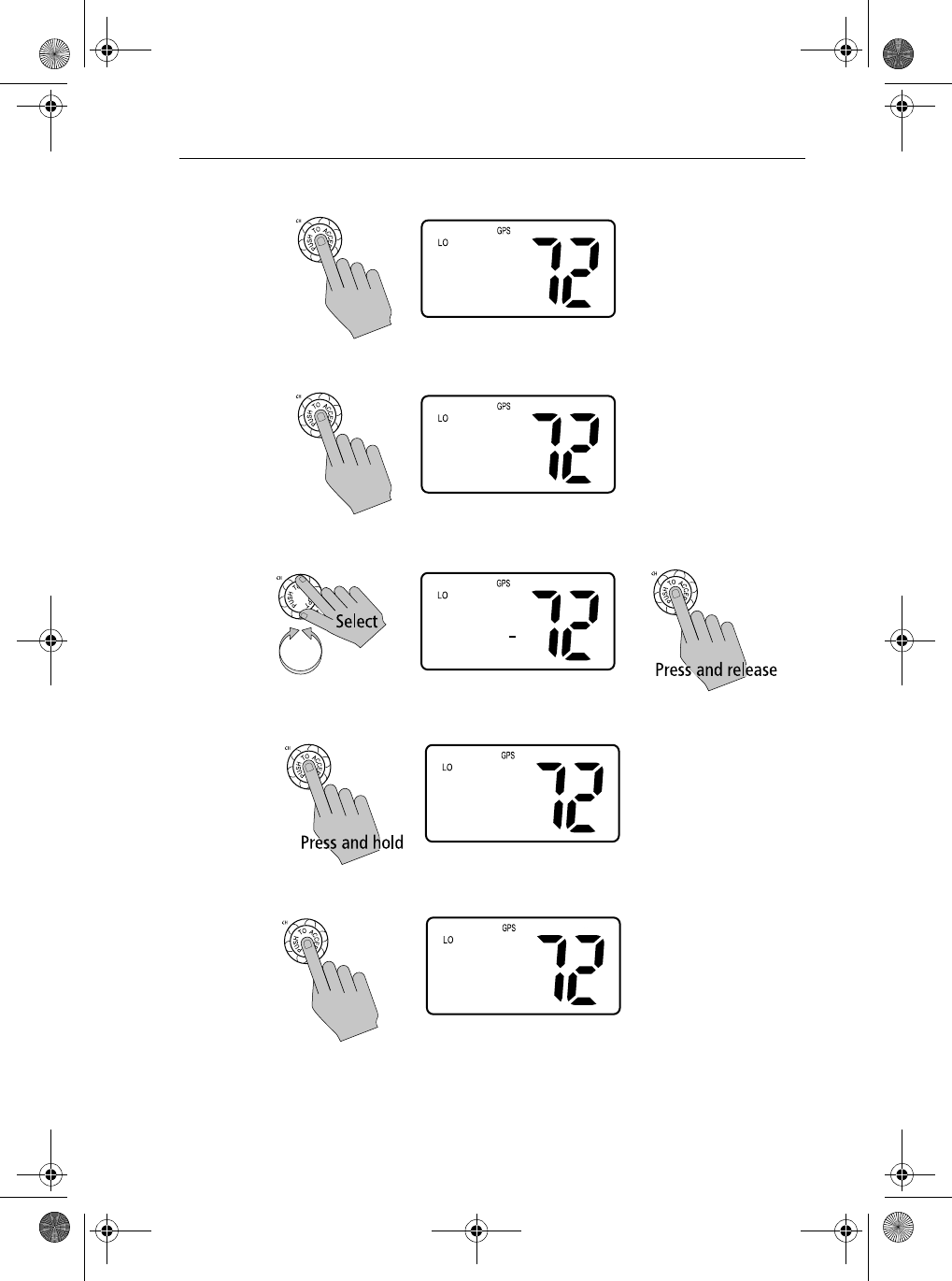
2. Rotate the CH knob to scroll down the list until the arrow points to GPS/
TIME.
3. Push in the CH knob. The arrow is pointing to MANUAL POS.
4. Push CH again to accept. The Manual Position screen appears.
5. Using the CH knob, fill in the numerical latitude information, one charac-
ter at a time:
i. Rotate the CH knob to scroll through the selections.
Note: The last selection in each field is a caret (<), which represents
a BACKSPACE. Accepting the caret returns the current character to
its default value and moves you back to the previous position.
ii. When the desired character appears, push in the CH knob to accept it.
The next position is ready to be selected.
Note: The next character to be filled in sequence is underlined (_).
>GPS/TIME
RADIO SETUP
DSC SETUP
RESET
>MANUAL POS
SETTINGS
BACK
MANUAL POS
-- --.----N
--- --.----E
--:-- UTC
81231_1.book Page 83 Thursday, April 22, 2004 5:21 PM
84 Ray54 VHF Radio
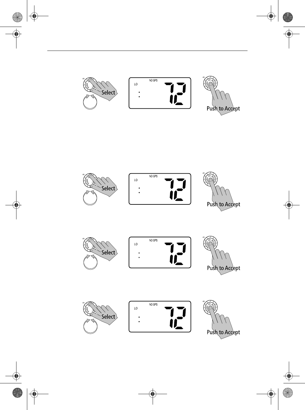
iii. Continue this process until all longitude numerical characters have
been selected.
Note: Pressing and holding the CH knob indicates you have com-
pleted editing the current line and forwards you to the first position of
the next line. This eliminates the need to accept each character indi-
vidually.
6. Next, select the latitude direction. Rotate the CH knob to scroll between N
and S. When the desired value appears, push the CH knob to accept.
7. Push the CH knob to accept the longitude and move on to the latitude
numerical data. Continue the process until all digits have been selected.
8. Next, select the longitude direction. Rotate the CH knob to scroll between
E and W. When the desired value appears, push the CH knob to accept.
9. Push in the CH knob to accept the latitude data and move onto UTC time.
Continue the process until all time characters have been selected.
MANUAL POS
27 34.1251N
--- --.----E
--:-- UTC
-
MANUAL POS
27 34.1251N
0-- --.----E
--:-- UTC
-
MANUAL POS
27 34.1251N
112 55.5623E
--:-- UTC -
MANUAL POS
27 34.1251N
112 55.5623W
0-:-- UTC
-
81231_1.book Page 84 Thursday, April 22, 2004 5:21 PM
Chapter 6: Menu Settings 85
Note: You must enter the TIME parameter in UTC time and not in local time.
When time data is entered manually, the NO GPS indicator remains
illuminated and the UTC designator appears following the time.
Note: When the final selection is made the radio returns to the previous
Menu Selection. To exit this sub-mode, select BACK or else press the 16/9 or
CLEAR/WX keys.
MANUAL POS
27°34.1251N
112°55.5623W
11:56 UTC
SHIP TO SHIP
27°34.1251N
112°55.5623W
11:56 UTC
81231_1.book Page 85 Thursday, April 22, 2004 5:21 PM
86 Ray54 VHF Radio
6.7 Settings
You can also set how some time and position information is displayed on the
screen:
•whether Lat/Lon data is displayed
•whether the Time is displayed
•whether a Time Zone Offset is used
•how the Time data is formatted
•whether COG/SOG data is displayed
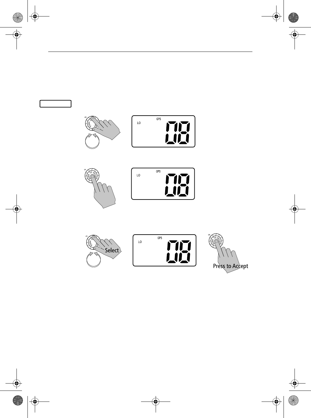
➤To adjust these Settings:
1. Press and hold the CALL/MENU key to enter Menu mode.
2. Rotate the CH knob until the arrow points to GPS/TIME.
3. Push the CH knob to accept. The GPS/Time screen appears.
4. Rotate the CH knob and scroll down the list to SETTINGS.
GPS/TIME
>PHONEBOOK
LOCAL/DIST
BACKLIGHT
CONTRAST
>GPS/TIME
RADIO SETUP
DSC SETUP
RESET
>MANUAL POS
SETTINGS
BACK
MANUAL POS
>SETTINGS
BACK
81231_1.book Page 86 Thursday, April 22, 2004 5:21 PM
Chapter 6: Menu Settings 87
5. Push the CH knob to accept.
Make your selection from the options on the list, which are described as
follows.
>LL DISPLY
TIME DISPLY
TIME OFFSET
TIME FORMAT
81231_1.book Page 87 Thursday, April 22, 2004 5:21 PM
88 Ray54 VHF Radio
Latitude/Longitude Display
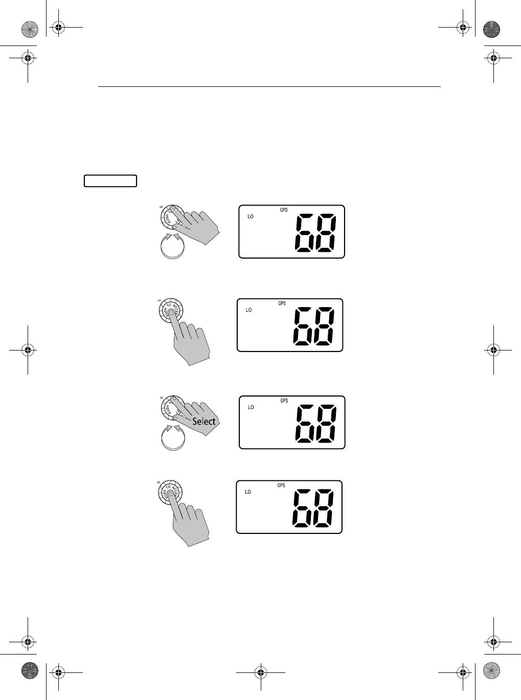
The LL/DISPLY setting indicates whether Latitude and Longitude position data
are displayed on the screen in normal mode.
1. From the GPS/TIME/SETTINGS menu item, rotate the CH knob until the
arrow points to LL DISPLY.
2. Push the CH knob to accept.
3. Rotate the CH knob to select whether you wish lat/lon data display to be
set ON or OFF. Push the CH knob to accept.
SETTINGS
>LL DISPLY
TIME DISPLY
TIME OFFSET
TIME FORMAT
LL DISPLY
>ON
OFF
LL DISPLY
ON
>OFF
81231_1.book Page 88 Thursday, April 22, 2004 5:21 PM
Chapter 6: Menu Settings 89
Time Display
The TIME DISPLY setting indicates whether time information is displayed on
the screen in normal mode.
➤To adjust the Time Display setting:
1. From the GPS/TIME/SETTINGS menu item, rotate the CH knob until the
arrow points to TIME DISPLY.
2. Push the CH knob to accept.
3. Rotate the CH knob to select whether you wish time data display to be set
ON or OFF. Push the CH knob to accept.
SETTINGS
>TIME DISPLY
TIME OFFSET
TIME FORMAT
COG/SOG
TIME DISPLY
>ON
OFF
TIME DISPLY
ON
>OFF
81231_1.book Page 89 Thursday, April 22, 2004 5:21 PM
90 Ray54 VHF Radio
Time Offset
The TIME OFFSET setting indicates the amount of time to add or subtract from
UTC time to equal your local time.
➤To adjust the Time Offset setting:
1. From the GPS/TIME/SETTINGS menu item, rotate the CH knob until the
arrow points to TIME OFFSET.
2. Push the CH knob to accept.
3. Rotate the CH knob until the desired offset time appears. The offset
changes in 0.5 hour increments.
Push the CH knob to accept. LOC appears following the time, indicating
local time is being displayed.
Note: The Time Offset setting is only available when valid GPS data is avail-
able. When manual time is used, it is always displayed as UTC time.
SETTINGS
>TIME OFFSET
TIME FORMAT
COG/SOG
BACK
TIME OFFSET
+ 0.0 HRS
06:56AM
PRESS ACCEPT
TIME OFFSET
+ 6.0 HRS
12:56PM LOC
PRESS ACCEPT
81231_1.book Page 90 Thursday, April 22, 2004 5:21 PM
Chapter 6: Menu Settings 91
Time Format
The TIME FORMAT setting indicates whether the time is displayed in 12 hour
or 24 hour format.
➤To adjust the Time Format setting:
1. From the GPS/TIME/SETTINGS menu item, rotate the CH knob until the
arrow points to TIME FORMAT.
2. Push in the CH knob to accept.
3. Rotate the CH knob until the arrow points to the desired time format.
4. Push CH again knob to accept.
To exit this sub-mode, press the 16/9 or CLEAR/WX keys, or else select the
BACK option from the menu.
SETTINGS
TIME OFFSET
>TIME FORMAT
COG/SOG
BACK
TIME FORMAT
12 HR
>24 HR
22:26 LOC
TIME FORMAT
>12 HR
24 HR
22:26 LOC
TIME FORMAT
>12 HR
24 HR
10:26PM LOC
81231_1.book Page 91 Thursday, April 22, 2004 5:21 PM
92 Ray54 VHF Radio
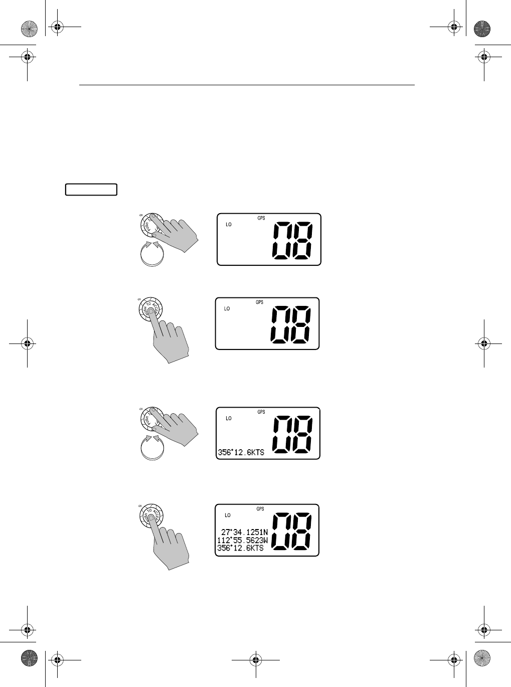
COG/SOG Display
This setting determines whether COG/SOG data is displayed on the display. If
COG/SOG is set ON, TIME DISPLY is automatically set to OFF; only one of
these two settings can be displayed at a time.
➤To adjust the COG/SOG setting:
1. From the GPS/TIME/SETTINGS menu item, rotate the CH knob until the
arrow points to COG/SOG.
2. Push in the CH knob to accept.
3. Rotate the CH knob to select whether you wish COG/SOG data display to
be set ON or OFF.
4. Push CH again to accept. COG/SOG data appears on the last line of the
dot matrix display.
To exit this sub-mode, press the 16/9 or CLEAR/WX keys, or else select the
BACK option from the menu.
GPS/TIMESETTINGS
TIME OFFSET
TIME FORMAT
>COG/SOG
BACK
COG/SOG
ON
>OFF
COG/SOG
>ON
OFF
81231_1.book Page 92 Thursday, April 22, 2004 5:21 PM
Chapter 6: Menu Settings 93
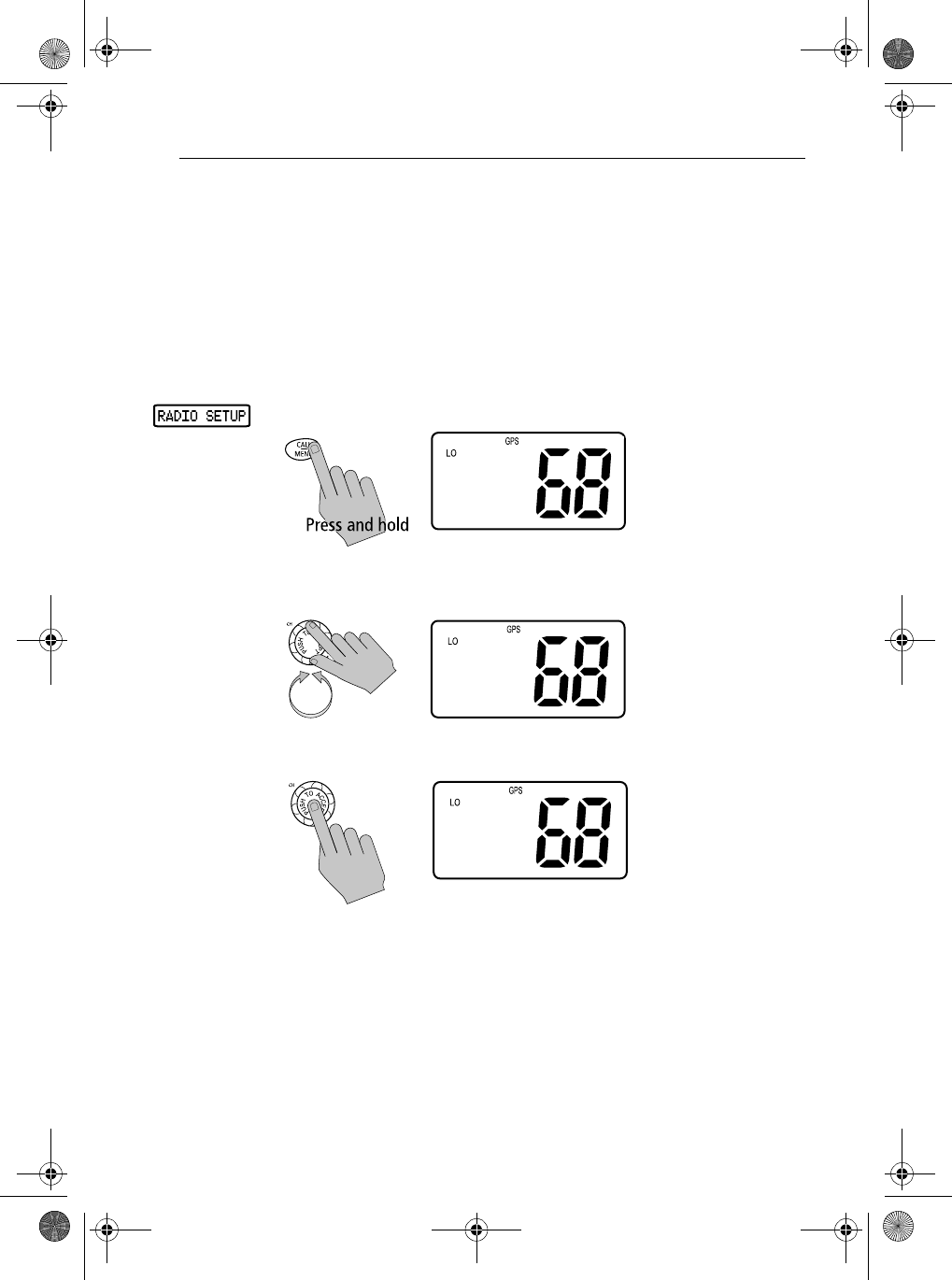
6.8 Radio Setup
The Radio Setup menu item is used to determine four separate settings:
•Frequency Band
•Channel Name
•Ring Volume
•Key Beep
➤To adjust these settings:
1. Press and hold the CALL/MENU key to enter Menu mode.
2. Rotate the CH knob to scroll down the list until the arrow points to RADIO
SETUP.
3. Push the CH knob to accept. The Radio Setup screen appears.
Make your selection from the options on the list, which are described as
follows.
>PHONEBOOK
LOCAL/DIST
BACKLIGHT
CONTRAST
>RADIO SETUP
DSC SETUP
RESET
EXIT
>BAND
CH NAME
RING VOLUME
KEY BEEP
81231_1.book Page 93 Thursday, April 22, 2004 5:21 PM
94 Ray54 VHF Radio
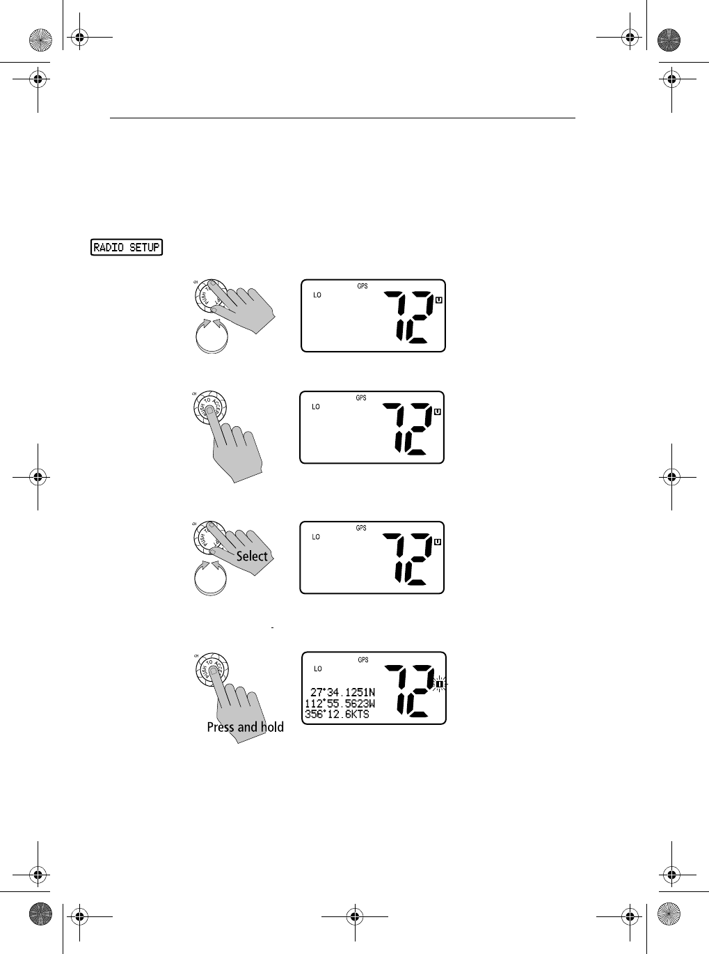
Frequency Band
The Ray54 can transmit and receive all USA, International and Canadian
frequencies. This setting determines which channel set is being used. he
appropriate indicator is illuminated in the LCD: U for US, I for International,
or C for Canadian channel sets.
1. From the RADIO SETUP menu item described on Radio Setup on page 6-
93, rotate the CH knob until the arrow points to BAND.
2. Push the CH knob to accept.
3. Rotate the CH knob until the arrow points to the desired frequency band.
4. Press and hold the CH knob to accept. The new corresponding Band icon
illuminates on the LCD.
To exit this sub-mode, press the 16/9 or CLEAR/WX keys, or else select the
BACK option from the menu.
>BAND
CH NAME
RING VOLUME
KEY BEEP
>USA
INT
CANADA
PRESS ACCEPT
USA
>INT
CANADA
PRESS ACCEPT
81231_1.book Page 94 Thursday, April 22, 2004 5:21 PM
Chapter 6: Menu Settings 95
Displaying the Channel Name
By default, the Ray54 lists a descriptive name in the dot matrix display for
each channel. You can toggle this Channel Name ON or OFF.
1. From the RADIO SETUP menu item described on page 93, rotate the CH
knob until the arrow points to CH NAME.
2. Push the CH knob to accept. The arrow points to DISPLAY NAME.
3. Push the CH knob to accept.
Note: The CH INFO option is used to edit the Channel Name. This is de-
scribed in the following Section , Editing an Existing Entry.
4. Rotate the CH knob until the arrow points to the desired setting: ON or
OFF. Push the CH knob to accept.
CH NAME
>CH NAME
RING VOLUME
KEY BEEP
BACK
CH NAME
>DISPLY NAME
CH INFO
BACK
DISPLY NAME
>ON
OFF
DISPLY NAME
ON
>OFF
81231_1.book Page 95 Thursday, April 22, 2004 5:21 PM
96 Ray54 VHF Radio
Editing a Channel Name Entry
Using this feature you can change the Channel Names from the default.
1. From the CH NAME menu item, rotate the CH knob until the arrow on the
dot matrix display points to CH INFO.
2. Push in the CH knob to select. The currently assigned channel name
appears.
3. Push the CH knob to display your options.
4. Push CH again to select EDIT.
5. Rotate the CH knob to scroll through values for the first character in the
NAME field. The character field you are editing is blinking.
All alpha and numeric characters are available. The first available char-
acter is a blank (space). The final available character is an arrow, which
serves as a backspace. A total of 11 character spaces are available.
CH NAME
CH NAME
DISPLY NAME
>CH INFO
BACK
CH NAME:
>SHIP TO SHIP
PRESS ACCEPT
FOR OPTIONS
CH NAME:
>EDIT
CLEAR
BACK
CH NAME:
>_
HOLD ACCEPT
TO FINALIZE
81231_1.book Page 96 Thursday, April 22, 2004 5:21 PM
Chapter 6: Menu Settings 97
When the desired character appears, press and release the CH knob to
accept it. The next position begins to blink, indicating it is ready to be
selected.
6. When you have completed the name, press and hold the CH knob to
accept. The new entry appears on the LCD.
Deleting a Channel Name Entry
Using this feature you can delete a Channel Name from the list.
1. From the CH NAME menu item, rotate the CH knob until the arrow on the
dot matrix display points to CH INFO.
2. Push the CH knob to select. The currently assigned channel name
appears.
CH NAME:
>F_
HOLD ACCEPT
TO FINALIZE
CH NAME:
>FISHING
PRESS ACCEPT
FOR OPTIONS
CH NAME
CH NAME
DISPLY NAME
>CH INFO
BACK
CH NAME:
>FISHING
PRESS ACCEPT
FOR OPTIONS
81231_1.book Page 97 Thursday, April 22, 2004 5:21 PM
98 Ray54 VHF Radio
3. Push CH again to display your options.
4. Rotate the CH knob to select CLEAR.
5. Push the CH knob to accept.
6. Push CH again. The name is cleared.
CH NAME:
>EDIT
CLEAR
BACK
CH NAME:
EDIT
>CLEAR
BACK
CLEAR NAME:
FISHING
>YES
NO
CH NAME:
>
PRESS ACCEPT
FOR OPTIONS
81231_1.book Page 98 Thursday, April 22, 2004 5:21 PM
Chapter 6: Menu Settings 99
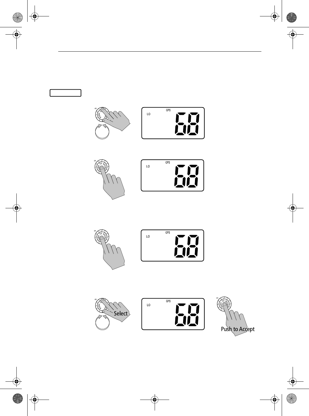
Ring Volume
This setting is used to set the volume of the ring that is sounded when an
incoming call is received.
➤To set the Ring volume:
1. From the RADIO SETUP menu item described on page 93, rotate the CH
knob until the arrow points to RING VOLUME.
2. Push the CH knob to accept.
3. Rotate the CH knob until the arrow points to the desired setting: HIGH or
LOW. Push the CH knob to accept.
SETTINGS
CH NAME
>RING VOLUME
KEY BEEP
BACK
RING VOLUME
>HIGH
LOW
RING VOLUME
HIGH
>LOW
81231_1.book Page 99 Thursday, April 22, 2004 5:21 PM
100 Ray54 VHF Radio
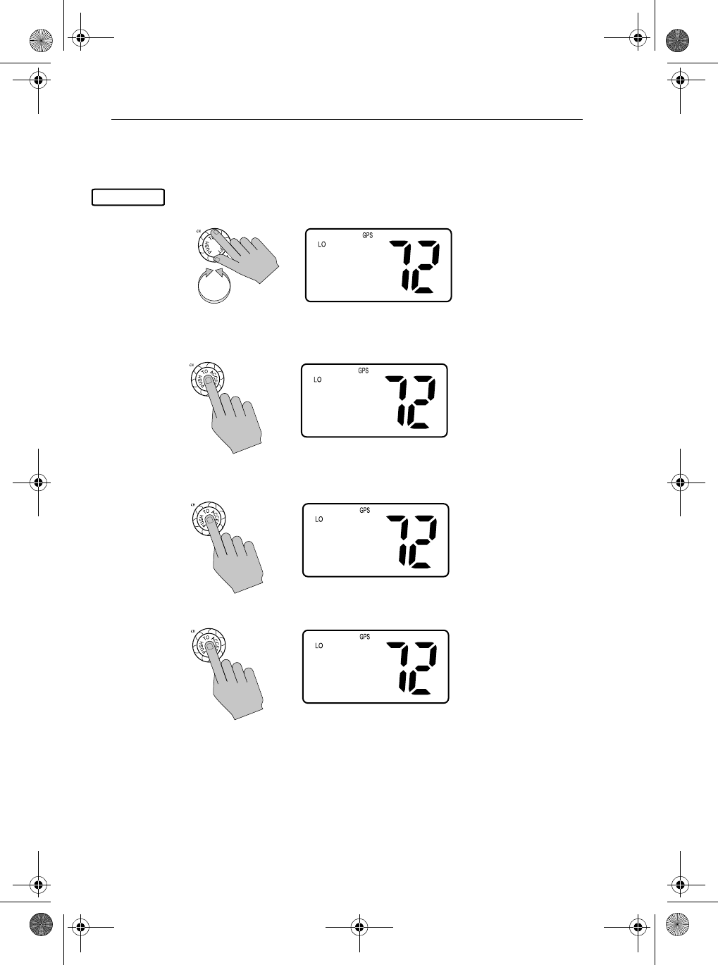
Key Beep
This setting is used to set the volume of the beep that sounds when a key is
pressed.
➤To set the Key Beep volume:
1. From the RADIO SETUP menu item described on page 93, rotate the CH
knob until the arrow points to KEY BEEP.
2. Push the CH knob to accept.
3. Rotate the CH knob until the arrow points to the desired setting: HIGH,
LOW or OFF. Push the CH knob to accept.
SETTINGS
CH NAME
RING VOLUME
>KEY BEEP
BACK
KEY BEEP
>HIGH
LOW
OFF
KEY BEEP
HIGH
>LOW
OFF
81231_1.book Page 100 Thursday, April 22, 2004 5:21 PM
Chapter 6: Menu Settings 101
6.9 DSC Setup
The DSC Setup menu item is used to determine these four functions:
•the radio’s MMSI ID number
•the radio’s Group MMSI ID number
•how your radio responds to a Position Reply request
•whether your radio automatically changes channels for DSC Calls
➤To adjust the DSC Settings:
1. Press and hold the CALL/MENU key to enter Menu mode.
2. Rotate the CH knob to scroll down the list until the arrow points to DSC
SETUP.
3. Push the CH knob to accept. The DSC Setup screen appears.
Make your selection from the following options:
•MY MMSI ID
•GROUP SETUP
•POS RPLY
•AUTO CH CHG
DSC SETUP
>PHONEBOOK
LOCAL/DIST
BACKLIGHT
CONTRAST
RADIO SETUP
>DSC SETUP
RESET
EXIT
DSC SETUP
>MY MMSI ID
GROUP SETUP
POS REPLY
81231_1.book Page 101 Thursday, April 22, 2004 5:21 PM
102 Ray54 VHF Radio
My MMSI ID
This operation stores the MMSI number required for DSC communications,
including distress calls.
If you try to access a DSC function before the MMSI number has been
entered, an error message appears and you are prompted to enter the MMSI
ID.
This is a one time operation. After the MMSI number has been programmed:
•you will not be able to change it
•only your dealer/distributor can change it
•accessing this menu item will display the programmed MMSI number
➤To enter or view the MMSI ID number:
1. From the DSC SETUP menu item described on page 101, rotate the CH
knob until the arrow points to MY MMSI ID.
2. Push the CH knob to accept. If an existing MMSI ID is stored, the value
appears. If the MMSI ID is blank, dashes appear, indicated that one has
yet to be entered.
3. To enter the MMSI ID number, rotate the CH knob or use the microphone
UP/ DOWN keys to scroll through the digits for entry into the MMSI ID
field. The final available character is an arrow, which serves as a back-
space. The character field you are editing is blinking.
DSC SETUP
DSC SETUP
>MY MMSI ID
GROUP SETUP
POS REPLY
INPUT MMSI
NUMBER
>_________
HOLD ACCEPT
81231_1.book Page 102 Thursday, April 22, 2004 5:21 PM
Chapter 6: Menu Settings 103
When the desired character appears, press and release the CH knob to
accept it. The next position begins to blink.
4. When all digits are selected, press and hold the CH knob to accept.
5. Re-enter all nine MMSI digits.
6. When complete, press and hold the CH knob to accept.
7. Press the CH knob one last time to save the MMSI ID number.
If the second entry does not match the first entry, the radio exits MY MMSI
ID and returns to the previous menu.
INPUT MMSI:
NUMBER
>7369596__
HOLD ACCEPT
INPUT MMSI:
ID AGAIN
>_________
HOLD ACCEPT
INPUT MMSI:
ID AGAIN
>736959651
HOLD ACCEPT
MY MMSI:
ID 736959651
>SAVE
CANCEL
MY MMSI:
ID 736959651
SAVED
81231_1.book Page 103 Thursday, April 22, 2004 5:21 PM
104 Ray54 VHF Radio
Group MMSI Setup
This operation sets up the MMSI number, which is used for DSC Group calls
between radios that share a common Group MMSI number.
You can program up to three Group MMSI ID numbers and associated Group
names, which can be up to 11 characters long. Group MMSI ID numbers
always begin with a zero (0). You only enter the last 8 digits of the Group I D
number; the initial “0” is automatically entered for you.
Adding a New Group
1. From the DSC SETUP menu item described on page page 101, rotate the
CH knob until the arrow points to GROUP SETUP.
2. Press the CH knob to accept. If an existing Group name and MMSI ID
number are already stored, those values appear. If blank, <EMPTY 1>,
<EMPTY 2>, and <EMPTY 3> are shown to indicate that the Group IDs
have not yet been programmed into the radio.
3. Rotate the CH knob until the arrow points to the first available empty
group location.
DSC SETUP
DSC SETUP
MY MMSI ID
>GROUP SETUP
POS REPLY
MY GROUP
>SEAWATCH
<EMPTY 2>
<EMPTY 3>
MY GROUP
SEAWATCH
><EMPTY 2>
<EMPTY 3>
81231_1.book Page 104 Thursday, April 22, 2004 5:21 PM
Chapter 6: Menu Settings 105
4. Press the CH knob to accept. The first field for you to enter data is the
Group Name. The initial character position is blinking.
5. Rotate the CH knob to scroll through values for the first character in the
NAME field.
All alpha and numeric characters are available. The first available char-
acter is a blank (space). The final available character is an arrow, which
serves as a backspace. A total of 11 character spaces are available.
When the desired character appears, press and release the CH knob to
accept it. The next position begins to blink, indicating it is ready to be
selected.
6. Continue this process until all GROUP NAME characters have been
entered. Press and hold the CH knob to accept the name and move on to
the GROUP ID.
7. Use the same procedure to enter the GROUP ID numbers.
GROUP NAME
>___________
GROUP ID:
ID0--------
GROUP NAME:
>RAYM_______
GROUP ID:
ID0________
GROUP NAME
>RAYMARINE
GROUP ID:
ID0--------
GROUP NAME:
>RAYMARINE
GROUP ID:
ID0876_____
81231_1.book Page 105 Thursday, April 22, 2004 5:21 PM
106 Ray54 VHF Radio
8. Press and hold the CH knob to accept.
9. Press the CH knob one more time to save. The new entry appears in the
list.
Editing an Existing Entry
1. From the DSC SETUP menu item described on page page 101, rotate the
CH knob until the arrow points to GROUP SETUP.
2. Press the CH knob to accept.
3. Rotate the CH knob until the arrow points to the group location you wish
to edit.
RAYMARINE
ID087654263
>SAVE
CANCEL
MY GROUP
SEAWATCH
>RAYMARINE
BACK
DSC SETUP
DSC SETUP
MY MMSI ID
>GROUP SETUP
POS REPLY
MY GROUP
>SEAWATCH
<EMPTY 2>
<EMPTY 3>
MY GROUP
SEAWATCH
>RAYMARINE
<EMPTY 3>
81231_1.book Page 106 Thursday, April 22, 2004 5:21 PM
Chapter 6: Menu Settings 107
4. Press the CH knob to select that Group.
5. Press the CH knob again to select EDIT.
6. Make your changes, using the CH knob.
7. Press and hold the CH knob to accept your changes.
8. Press the CH knob to save. The revised entry appears in the list.
RAYMARINE
>EDIT
CLEAR
BACK
GROUP NAME:
>RAYMARINE_
GROUP ID:
ID087654263
GROUP NAME:
>RAYMARINER
GROUP ID:
ID087654263
RAYMARINER
ID087654263
>SAVE
CANCEL
MY GROUP
SEAWATCH
>RAYMARINER
BACK
81231_1.book Page 107 Thursday, April 22, 2004 5:21 PM
108 Ray54 VHF Radio
Position Reply
This option enables you to determine how your radio responds to a request
for your GPS position information (lat/lon) from another station.
➤To enable/disable Position Reply:
1. From the DSC SETUP menu item described on page page 101, rotate the
CH knob until the arrow points to POS REPLY.
2. Press the CH knob to accept.
3. Rotate the CH knob to select the desired setting. Press the CH knob to
accept.
AUTOMATIC sends out your vessel’s position data as soon as it is requested.
MANUAL sends out the data only after you respond to the request.
OFF will not send position data under any circumstances.
The default setting is MANUAL.
Note: The Position Reply function is only available when a working GPS is
connected to the radio.
DSC SETUP
DSC SETUP
MY ATIS ID
ATIS FUNC
>POS REPLY
POS REPLY
AUTOMATIC
>MANUAL
OFF
POS REPLY
>AUTOMATIC
MANUAL
OFF
81231_1.book Page 108 Thursday, April 22, 2004 5:21 PM
Chapter 6: Menu Settings 109
Automatic Channel Changing of DSC Calls
DSC calls have encoded within them the working channel on which the
caller wishes to converse once the call is received. This option determines
whether you want your radio automatically switched to the indicated channel
or instead to be prompted to receive or decline the incoming DSC call.
This feature is useful for preventing your radio from automatically switching
channels while you are, for example, maintaining a continous watch on a
certain channel (say, in a VTS controlled area) or working with other vessels
(say, for towage).
By regulation, this feature cannot disable the automatic switching of
Individual Distress and Individual Urgency Alerts.
➤To enable/disable Channel Change:
1. From the DSC SETUP menu item described on page page 101, rotate the
CH knob until the arrow points to AUTO CH CHG.
2. Press the CH knob to accept.
Procedure When Enabled
If you accept ENABLE, your Ray54 automatically changes to the channel
indicated in the received DSC call.
The default setting is ENABLE.
Procedure When Disabled
If you accept DISABLE, on receipt of a DSC call you are presented with brief
details of the call and advised that a channel change has been requested. You
can either accept the channel change by pressing ACCEPT (CH knob) or
DSC SETUP
DSC SETUP
GROUP SETUP
POS REPLY
>AUTO CH CHG
AUTO CH CHG
>ENABLE
DISABLE
81231_1.book Page 109 Thursday, April 22, 2004 5:21 PM
110 Ray54 VHF Radio
decline by pressing CLEAR and thus remain monitoring the originally chosen
channel.
If you ignore the call, after 5 minutes the radio declines the call, records the
call in the Call Log and maintains normal operation.
If you accept the call, the Distress call is received, a tone sounds and the radio
is changed to channel 16. Pressing any key disables the alarm. When position
and time data is included in the signal, it is displayed in the text area of the
LCD. If invalid GPS or Time data is received, the lat/lon position shows 9s in
all digits and all 8s for the time. The two alternating pages of data are
recorded in the Distress Call Log.
DISTRESS
736959651
26°04.2172N
080°09.0933W
DISTRESS
736959651
SINKING
12:45PM LOC
CH CHANGE
REQUESTED
PRESS ACCEPT
OR PRESS CLR
CHANNEL HAS
BEEN CHANGED
736959651
26°04.2172N
080°09.0933W
18:21 PM LOC
PRESS
ACCPEPT
5 SECS
81231_1.book Page 110 Thursday, April 22, 2004 5:21 PM
Chapter 6: Menu Settings 111
6.10 Resetting Factory Defaults
This feature resets all radio settings back to their factory defaults, except MY
MMSI ID number and the PHONEBOOK list.
➤To perform the reset:
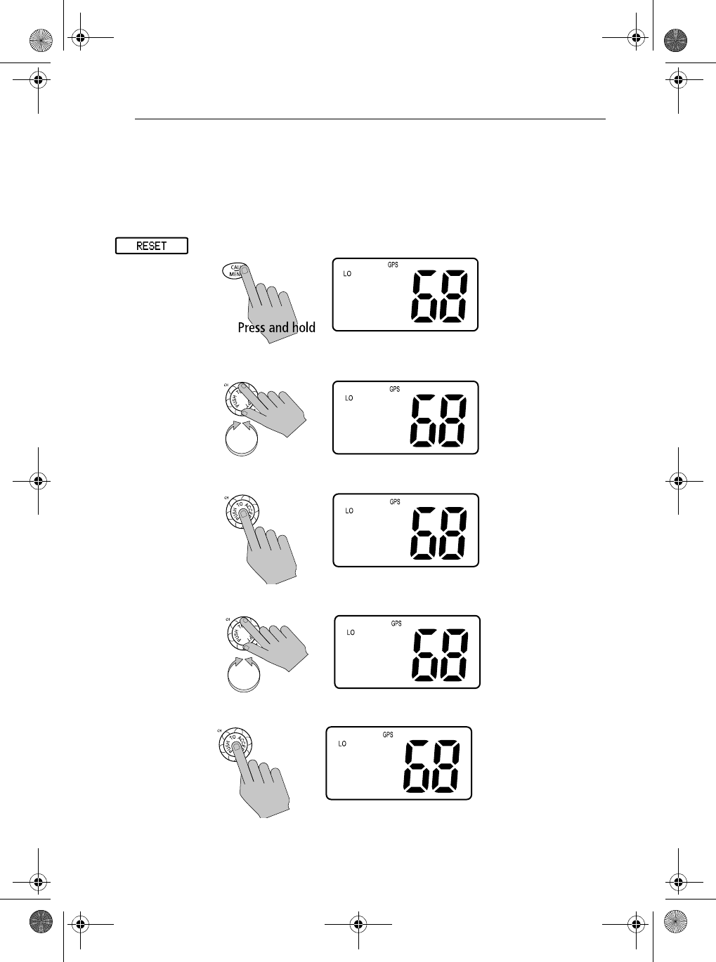
1. Press and hold the CALL/MENU key to enter Menu mode.
2. Rotate the CH knob to scroll down the list until the arrow points to RESET.
3. Press the CH knob to accept. The Reset screen appears.
4. Rotate the CH knob until arrow points to YES.
5. Press the CH knob to accept.
>PHONEBOOK
LOCAL/DIST
BACKLIGHT
CONTRAST
RADIO SETUP
DSC SETUP
>RESET
EXIT
RESET TO
DEFAULTS
>NO
YES
RESET TO
DEFAULTS
NO
>YES
ALL SETTINGS
RESTORED
TO FACTORY
DEFAULTS
81231_1.book Page 111 Thursday, April 22, 2004 5:21 PM

112 Ray54 VHF Radio
81231_1.book Page 112 Thursday, April 22, 2004 5:21 PM
Appendix A: Specifications 113
Appendix A: Specifications
General
Receiver
Size (H x W x D) 3.11” (79 mm) x 6.57” (167 mm) x 6.73” (171mm)
Weight 2.87 lbs (1.3kg)
Mounting Bracket or flush mount
Power 13.6 VDC ±15%
Environmental:
Operating Range:
Storage Range:
Humidity:
Waterproof to IPX7
–15°C to +55°C
–20°C to +70°C
up to 95%
Frequency Range:
Transmit
Receive
156.050 To 157.425 MHz
156.050 To 163.275 MHz
Channels All available US, Canadian and International VHF Marine
Band.
Frequency Range 156.025 to 157.425MHz
Oscillate Mode PLL
Modulation FM(16F3)
Channel Spacing 25 kHz Increments
Frequency Stability +/- 10PPM (+/- 0.001%)
Intermediate Frequency:
1st
2nd
MHz
455 KHz
Sensitivity 12dB SINAD = 0 (EMF) db µV
Squelch Sensitivity 3 db µV at Tight
Spurious Response Rejection Ratio 70 dB
Adjacent Channel Selectivity 70 dB
Intermodulation Rejection Ratio 68dB
S/N at 3KHz Dev. 40 dB
81231_1.book Page 113 Thursday, April 22, 2004 5:21 PM
114 Ray54 VHF Radio
Transmitter
Audio Output Power At THD 10% 2 W
Audio Distortion 10%
Audio Response EIA STANDARD dB
Current Drain at:
Max Audio Power
Stand-By
1.5 A
0.5 A
RF Power:
Hi Mode
Lo Mode
23 ±2 W
0.8 ± 0.1 W
Maximum Deviation ±5 KHz
S/N at 3KHz Dev 35 dB
Modulation Distortion 3KHz </= 7%
Audio Response 1KHz EIA STANDARD dB
Spurious/Harmonic Emissions:
Hi Power
Lo Power
__ dB
__ dB
Modulation Sensitivity </= 12mv
Current Drain At 13.8V DC:
Hi Power
Lo Power
</= 6 A
</= 1.5A
81231_1.book Page 114 Thursday, April 22, 2004 5:21 PM
Appendix B: Channel List 115
Appendix B: Channel List
U.S. VHF Marine Radio Channels and Frequencies
CH.
No
XMIT
Freq
RCV
Freq
Single
Freq Use
01A 156.050 156.050 x Port Operations and Commercial, VTS.
Available only in New Orleans / Lower Mississippi area.1
03A 156.150 156.150 x U.S. Government only
05A 156.250 156.250 x Port Operations or VTS in the Houston, New Orleans and Seattle
areas.
06 156.300 156.300 x Intership Safety
07A 156.350 156.350 x Commercial
08 156.400 156.400 x Commercial (Intership only)
09 156.450 156.450 x Boater Calling. Commercial and Non-Commercial.
10 156.500 156.500 x Commercial
11 156.550 156.550 x Commercial. VTS in selected areas.
12 156.600 156.600 x Port Operations. VTS in selected areas.
13 156.650 156.650 x Intership Navigation Safety (Bridge-to-bridge). Ships >20meters in
length maintain a listening watch on this channel in US waters.2
14 156.700 156.700 x Port Operations. VTS in selected areas.
15 –156.750 x Environmental (Receive only). Used by Class ‘C’ EPIRBs.
16 156.800 156.800 x International Distress, Safety and Calling. Ships required to carry
radio, USCG, and most coast stations maintain a listening watch on
this channel.3 HAILING
17 156.850 156.850 x State Control
18A 156.900 156.900 x Commercial
19A 156.950 156.950 x Commercial
20 157.000 161.600 Port Operations (duplex)
20A 157.000 157.000 x Port Operations
21A 157.050 157.050 x U.S. Coast Guard only
81231_1.book Page 115 Thursday, April 22, 2004 5:21 PM
116 Ray54 VHF Radio
22A 157.100 157.100 x Coast Guard Liaison and Maritime Safety Information Broadcasts.
Broadcasts announced on channel 16.
23A 157.150 157.150 x U.S. Coast Guard only
24 157.200 161.800 Public Correspondence (Marine Operator)
25 157.250 161.850 Public Correspondence (Marine Operator)
26 157.300 161.900 Public Correspondence (Marine Operator)
27 157.350 161.950 Public Correspondence (Marine Operator)
28 157.400 162.000 Public Correspondence (Marine Operator)
61A 156.075 156.075 x U.S. Government only
63A 156.175 156.175 x Port Operations and Commercial, VTS. Available only in New
Orleans / Lower Mississippi area.
64A 156.225 156.225 x U.S. Coast Guard only
65A 156.275 156.275 x Port Operations
66A 156.325 156.325 x Port Operations
67 156.375 156.375 x Commercial. Used for Bridge-to-bridge communications in lower
Mississippi River. Intership only.
68 156.425 156.425 x Non-Commercial
69 156.475 156.475 x Non-Commercial
71 156.575 156.575 x Non-Commercial
72 156.625 156.625 x Non-Commercial (Intership only)
73 156.675 156.675 x Port Operations
74 156.725 156.725 x Port Operations
77 156.875 156.875 x Port Operations (Intership only)
78A 156.925 156.925 x Non-Commercial
79A 156.975 156.975 x Commercial. Non-Commercial in Great Lakes only.
80A 157.025 157.025 x Commercial. Non-Commercial in Great Lakes only
81A 157.075 157.075 x U.S. Government only – Environmental protection operations.
CH.
No
XMIT
Freq
RCV
Freq
Single
Freq Use
81231_1.book Page 116 Thursday, April 22, 2004 5:21 PM
Appendix B: Channel List 117
•Boaters should normally use channels listed as Non-Commercial.
•Channel 70 is used exclusively for Digital Selective Calling (DSC) and is not avail-
able for regular voice communications.
•Channels 75 and 76 are reserved as guard bands for Channel 16 and are not available
for regular voice communications.
Notes:
1. The letter “A” following a channel number indicates simplex use of the ship station
transmit side of an international duplex channel. Operations are different from that
of international operations on that channel.
2. Channel 13 should be used to contact a ship when there is danger of collision. All
ships of length 20 meters or greater are required to guard VHF channel 13, in addi-
tion to VHF channel 16, when operating within U.S. territorial waters.
3. Channel 16 is used to hail other stations or for distress alerting.
82A 157.125 157.125 x U.S. Government only
83A 157.175 157.175 x U.S. Coast Guard only
84 157.225 161.825 Public Correspondence (Marine Operator)
85 157.275 161.875 Public Correspondence (Marine Operator)
86 157.325 161.925 Public Correspondence (Marine Operator)
87 157.375 161.975 Public Correspondence Marine Operator)
88 157.425 162.025 Public Correspondence only near Canadian border
88A 157.425 157.425 x Commercial, Intership only
CH.
No
XMIT
Freq
RCV
Freq
Single
Freq Use
81231_1.book Page 117 Thursday, April 22, 2004 5:21 PM
118 Ray54 VHF Radio
Canadian VHF Marine Radio Channels and Frequencies
CH
No.
XMIT
Freq
RCV
Freq
Area of
Operation Use
01 156.050 160.650 PC Public Correspondence
02 156.100 160.700 PC Public Correspondence
03 156.150 160.750 PC Public Correspondence
04A 156.200 156.200 PC Intership, Ship/Shore and Safety:
Canadian Coast Guard search and rescue1
04A 156.200 156.200 EC Intership, Ship/Shore and Commercial:
Commercial fishing only
05A 156.250 156.250 Ship Movement
06 156.300 156.300 All areas Intership, Commercial, Non-commercial and Safety:
May be used for search and rescue communications between
ships and aircraft.
07A 156.350 156.350 All areas Intership, Ship/Shore, Commercial
08 156.400 156.400 WC, EC Intership, Commercial and Safety:
Also assigned for operations in the Lake Winnipeg area.
09 156.450 156.450 AC Intership, Ship/Shore, Commercial, Non-commercial and Ship
Movement: May be used to communicate with aircraft and
helicopters in predominantly maritime support operations.
10 156.500 156.500 AC, GL Intership, Ship/Shore, Commercial, Non-commercial, Safety
and Ship Movement: May also be used for communications
with aircraft engaged in coordinated search and rescue and
antipollution operations.
11 156.550 156.550 PC, AC, GL Intership, Ship/Shore, Commercial, Non-commercial and Ship
Movement: Also used for pilotage purposes.
12 156.600 156.600 WC, AC, GL Intership, Ship/Shore, Commercial, Non-commercial and Ship
Movement: Port operations and pilot information and mes-
sages.
13 156.650 156.650 All areas Intership, Commercial, Non-commercial and Ship Movement:
Exclusively for bridge-to-bridge navigational traffic.
14 156.700 156.700 AC, GL Intership, Ship/Shore, Commercial, Non-commercial and Ship
Movement: Port operations and pilot information and mes-
sages.
81231_1.book Page 118 Thursday, April 22, 2004 5:21 PM
Appendix B: Channel List 119
15 156.750 156.750 All areas Intership, Ship/Shore, Commercial, Non-commercial and Ship
Movement: All operations limited to 1-watt maximum power.
May also be used for on-board communications.
16 156.800 156.800 All areas International Distress, Safety and Calling2
17 156.850 156.850 All areas Intership, Ship/Shore, Commercial, Non-commercial and Ship
Movement: All operations limited to 1-watt maximum power.
May also be used for on-board communications.
18A 156.900 156.900 All areas Intership, Ship/Shore and Commercial:
Towing on the Pacific Coast.
19A 156.950 156.950 All areas
except PC
Intership and Ship/Shore:
Canadian Coast Guard only.
19A 156.950 156.950 PC Intership and Ship/Shore:
Various Government departments.
20 157.000 161.600 All areas Ship/Shore, Safety and Ship Movement:
Port operations only with 1-watt maximum power.
21A 157.050 157.050 All areas Intership and Ship/Shore:
Canadian Coast Guard only.
21B - 161.650 All areas Safety: Continuous Marine Broadcast (CMB) service.3
22A 157.100 157.100 All areas Intership, Ship/Shore, Commercial and Non-commercial:
For communications between Canadian Coast Guard and non-
Canadian Coast Guard stations only.
23 157.150 161.750 PC Ship/Shore and Public Correspondence:
Also in the inland waters of British Columbia and the Yukon.
24 157.200 161.800 All areas Ship/Shore and Public Correspondence
25 157.250 161.850 PC Ship/Shore and Public Correspondence: Also assigned for
operations in the Lake Winnipeg area.
25B - 161.850 AC Safety: Continuous Marine Broadcast (CMB) service.
26 157.300 161.900 All areas Ship/Shore, Safety and Public Correspondence
27 157.350 161.950 AC, GL, PC Ship/Shore and Public Correspondence
28 157.400 162.000 PC Ship/Shore, Safety and Public Correspondence
28B - 162.000 AC Safety: Continuous Marine Broadcast (CMB) service.
CH
No.
XMIT
Freq
RCV
Freq
Area of
Operation Use
81231_1.book Page 119 Thursday, April 22, 2004 5:21 PM
120 Ray54 VHF Radio
60 156.025 160.625 PC Ship/Shore and Public Correspondence
61A 156.075 156.075 PC Intership and Ship/Shore:
Canadian Coast Guard only.
61A 156.075 156.075 EC Intership, Ship/Shore and Commercial:
Commercial fishing only.
62A 156.125 156.125 PC Intership and Ship/Shore:
Canadian Coast Guard only.
62A 156.125 156.125 EC Intership, Ship/Shore and Commercial:
Commercial fishing only.
64 156.225 160.825 PC Ship/Shore and Public Correspondence
64A 156.225 156.225 EC Intership, Ship/Shore and Commercial:
Commercial fishing only.
65A 156.275 156.275 Intership, Ship/Shore, Commercial, Non-commercial, Safety:
Search & rescue and antipollution operations on the Great
Lakes. Towing on the Pacific Coast. Port operations only in the
St. Lawrence River areas with 1W maximum power. Pleasure
craft in the inland waters of Alberta, Saskatchewan and Mani-
toba (excluding Lake Winnipeg and the Red River).
66A 156.325 156.325 Intership, Ship/Shore, Commercial, Non-commercial, Safety
and Ship Movement: Port operations only in the St.Lawrence
River/Great Lakes Areas with 1-watt maximum power.
67 156.375 156.375 EC Intership, Ship/Shore and Commercial:
Commercial fishing only.
67 156.375 156.375 All areas
except EC
Intership, Ship/Shore, Commercial, Non-commercial, Safety:
May also be used for communications with aircraft engaged in
coordinated search and rescue and antipollution operations.
68 156.425 156.425 All areas Intership, Ship/Shore and Non-commercial:
For marinas and yacht clubs.
69 156.475 156.475 All areas
except EC
Intership, Ship/Shore, Commercial and Non-commercial
69 156.475 156.475 EC Intership, Ship/Shore and Commercial:
Commercial fishing only.
71 156.575 156.575 PC Intership, Ship/Shore, Commercial, Non-commercial, Safety
and Ship Movement
CH
No.
XMIT
Freq
RCV
Freq
Area of
Operation Use
81231_1.book Page 120 Thursday, April 22, 2004 5:21 PM

Appendix B: Channel List 121
71 156.575 156.575 Intership, Ship/Shore and Non-commercial: For marinas and
yacht clubs on the East Coast and on Lake Winnipeg.
72 156.625 156.625 EC, PC Intership, Commercial and Non-commercial:
May be used to communicate with aircraft and helicopters in
predominantly maritime support operations.
73 156.675 156.675 EC Intership, Ship/Shore and Commercial:
Commercial fishing only
73 156.675 156.675 All areas
except EC
Intership, Ship/Shore, Commercial, Non-commercial, Safety:
May also be used for communications with aircraft engaged in
coordinated search and rescue and antipollution operations.
74 156.725 156.725 EC, PC Intership, Ship/Shore, Commercial, Non-commercial and Ship
Movement.
77 156.875 156.875 Intership, Ship/Shore, Safety and Ship Movement:
Pilotage on Pacific Coast. Port operations only in the St.
Lawrence River/Great Lakes areas with 1W maximum power.
78A 156.925 156.925 EC, PC Intership, Ship/Shore and Commercial
79A 156.975 156.975 EC, PC Intership, Ship/Shore and Commercial
80A 157.025 157.025 EC, PC Intership, Ship/Shore and Commercial
81A 157.075 157.075 Intership and Ship/Shore: Canadian Coast Guard use only in
the St. Lawrence River/Great Lakes areas.
81A 157.075 157.075 PC Intership, Ship/Shore and Safety:
Canadian Coast Guard antipollution.
82A 157.125 157.125 PC Intership, Ship/Shore and Safety:
Canadian Coast Guard use only.
82A 157.125 157.125 Intership and Ship/Shore: Canadian Coast Guard use only in
the St. Lawrence River/Great Lakes areas.
83 157.175 161.775 PC Ship/Shore and Safety:
Canadian Coast Guard use only.
83A 157.175 157.175 EC Intership and Ship/Shore:
Canadian Coast Guard and other Government agencies.
83B - 161.775 AC, GL Safety: Continuous Marine Broadcast (CMB) Service.
84 157.225 161.825 PC Ship/Shore and Public Correspondence
CH
No.
XMIT
Freq
RCV
Freq
Area of
Operation Use
81231_1.book Page 121 Thursday, April 22, 2004 5:21 PM
122 Ray54 VHF Radio
Area of Operation
AC: Atlantic Coast, Gulf and St. Lawrence River up to and including Montreal
EC (East Coast): includes NL, AC, GL and Eastern Arctic areas
GL: Great Lakes (including St. Lawrence above Montreal)
NL: Newfoundland and Labrador
PC: Pacific Coast
WC (West Coast): Pacific Coast, Western Arctic and Athabasca-Mackenzie Watershed areas
All areas: includes East and West Coast areas
Notes:
1. The letter “A” following a channel number indicates simplex use of the ship station transmit
side of an international duplex channel. Operations are different from that of international
operations on that channel.
2. Channel 16 is used for calling other stations or for distress alerting.
3. The letter “B” following a channel number indicates simplex use of the coast station transmit
side of an international duplex channel. That is, the channel is Receive Only.
4. Channel 70 is used exclusively for Digital Selective Calling (DSC) and is not available for
regular voice communications.
5. Channels 75 and 76 are reserved as guard bands for Channel 16 and are not available for reg-
ular voice communications.
85 157.275 161.875 AC, GL, NL Ship/Shore and Public Correspondence
86 157.325 161.925 PC Ship/Shore and Public Correspondence
87 157.375 161.975 AC, GL, NL Ship/Shore and Public Correspondence
88 157.425 162.025 AC, GL, NL Ship/Shore and Public Correspondence
CH
No.
XMIT
Freq
RCV
Freq
Area of
Operation Use
81231_1.book Page 122 Thursday, April 22, 2004 5:21 PM
Appendix B: Channel List 123
International VHF Marine Radio Channels & Frequencies
CH
No.
XMIT
Freq
RCV
Freq
Single
Freq Use
01 156.050 160.650 Public Correspondence, Port Operations and Ship Movement
02 156.100 160.700 Public Correspondence, Port Operations and Ship Movement
03 156.150 160.750 Public Correspondence, Port Operations and Ship Movement
04 156.200 160.800 Public Correspondence, Port Operations and Ship Movement
05 156.250 160.850 Public Correspondence, Port Operations and Ship Movement
06 156.300 156.300 x Intership 1
07 156.350 160.950 Public Correspondence, Port Operations and Ship Movement
08 156.400 156.400 x Intership
09 156.450 156.450 x Intership, Port Operations and Ship Movement
10 156.500 156.500 x Intership, Port Operations and Ship Movement 2
11 156.550 156.550 x Port Operations and Ship Movement
12 156.600 156.600 x Port Operations and Ship Movement
13 156.650 156.650 x Intership Safety, Port Operations and Ship Movement 3
14 156.700 156.700 x Port Operations and Ship Movement
15 156.750 156.750 x Intership and On-board Communications at 1W only 4
16 156.800 156.800 x Distress, Safety and Calling
17 156.850 156.850 x Intership and On-board Communications at 1W only 4
18 156.900 161.500 Public Correspondence
19 156.950 161.550 Public Correspondence, Port Operations and Ship Movement
20 157.000 161.600 Public Correspondence, Port Operations and Ship Movement
21 157.050 161.650 Public Correspondence, Port Operations and Ship Movement
22 157.100 161.700 Public Correspondence, Port Operations and Ship Movement
23 157.150 161.750 Public Correspondence, Port Operations and Ship Movement
24 157.200 161.800 Public Correspondence, Port Operations and Ship Movement
81231_1.book Page 123 Thursday, April 22, 2004 5:21 PM
124 Ray54 VHF Radio
25 157.250 161.850 Public Correspondence, Port Operations and Ship Movement
26 157.300 161.900 Public Correspondence, Port Operations and Ship Movement
27 157.350 161.950 Public Correspondence, Port Operations and Ship Movement
28 157.400 162.000 Public Correspondence, Port Operations and Ship Movement
60 156.025 160.625 Public Correspondence, Port Operations and Ship Movement
61 156.075 160.675 Public Correspondence, Port Operations and Ship Movement
62 156.125 160.725 Public Correspondence, Port Operations and Ship Movement
63 156.175 160.775 Public Correspondence, Port Operations and Ship Movement
64 156.225 160.825 Public Correspondence, Port Operations and Ship Movement
65 156.275 160.875 Public Correspondence, Port Operations and Ship Movement
66 156.325 160.925 Public Correspondence, Port Operations and Ship Movement
67 156.375 156.375 x Intership, Port Operations and Ship Movement
68 156.425 156.425 x Port Operations and Ship Movement
69 156.475 156.475 x Port Operations and Ship Movement
71 156.575 156.575 x Port Operations and Ship Movement
72 156.625 156.625 x Intership
73 156.675 156.675 x Intership 2
74 156.725 156.725 x Port operations and Ship movement
75 156.775 156.775 x See Note 5
76 156.825 156.825 x See Note 5
77 156.875 156.875 x Intership
78 156.925 161.525 Public correspondence, Port Operations and Ship Movement
79 156.975 161.575 Public correspondence, Port Operations and Ship Movement
80 157.025 161.625 Public correspondence, Port Operations and Ship Movement
81 157.075 161.675 Public correspondence, Port Operations and Ship Movement
82 157.125 161.725 x Public correspondence, Port Operations and Ship Movement
CH
No.
XMIT
Freq
RCV
Freq
Single
Freq Use
81231_1.book Page 124 Thursday, April 22, 2004 5:21 PM
Appendix B: Channel List 125
•Intership channels are for communications between ship stations. Intership commu-
nications should be restricted to Channels 6, 8, 72 and 77. If these are not available,
the other channels marked for Intership may be used.
•Channels 10, 67 and 73 should be avoided within VHF range of coastal areas in
Europe and Canada.
•Channel 70 is used exclusively for Digital Selective Calling (DSC) and is not avail-
able for regular voice communications.
Notes:
1. Channel 06 may also be used for communications between ship stations and aircraft
engaged in coordinated search and rescue operations. Ship stations should avoid
harmful interference to such communications on channel 06 as well as to communi-
cations between aircraft stations, ice breakers and assisted ships during ice seasons.
2. Channels 10 or 73 (depending on location) are also used for the broadcast of Marine
Safety Information by the Maritime and Coast Guard Agency in the UK only.
3. Channel 13 is designated for use on a worldwide basis as a navigation safety com-
munication channel, primarily for intership navigation safety communications.
4. Channels 15 and 17 may also be used for on-board communications provided the
effective radiated power does not exceed 1 Watt.
5. The use of Channels 75 and 76 should be restricted to navigation related communi-
cation only and all precautions should be taken to avoid harmful interference to
channel 16. Transmit power is limited to 1 Watt.
83 157.175 161.775 x Public correspondence, Port Operations and Ship Movement
84 157.225 161.825 x Public correspondence, Port Operations and Ship Movement
85 157.275 161.875 x Public correspondence, Port Operations and Ship Movement
86 157.325 161.925 x Public correspondence, Port Operations and Ship Movement
87 157.375 157.375 Port Operations and Ship Movement
88 157.425 157.425 Port Operations and Ship Movement
CH
No.
XMIT
Freq
RCV
Freq
Single
Freq Use
81231_1.book Page 125 Thursday, April 22, 2004 5:21 PM
126 Ray54 VHF Radio
WX Channels (North America only)
Weather
Channel
Frequency
in MHz
WX 1 162.550
WX 2 162.400
WX 3 162.475
WX 4 162.425
WX 5 162.450
WX 6 162.500
WX 7 162.525
WX 8 161.650
WX 9 161.775
WX 10 163.275
81231_1.book Page 126 Thursday, April 22, 2004 5:21 PM
Appendix C: Glossary 127
Appendix C: Glossary
Term Meaning
All Scan A feature that scans all channels.
Canadian Channels Channel designator as defined by Industry Canada.
CH Channel selection key
DSC Digital Selective Calling
Dual Watch A feature that monitors the Priority Channel 16 while working on
another channel.
Duplex Transmit and receive on different frequencies
FCC Federal Communications Commission (US)
International Channels Channel designator as defined by the ITU
ITU International Telecommunications Union (EU)
LCD Liquid Crystal Display
MMSI Maritime Mobile Service Identity; a number issued by each country
to identify maritime stations
NOAA National Oceanographic and Atmospheric Administration (USA)
Priority Channel Channel 16 or 9
Priority Scan (PSCAN) A feature that alternates monitoring the Priority Channel 16 with
each of the regular channels
PTT switch Microphone push-to-talk switch
RF Radio Frequency
RX Receive
Saved Scan Scans only user-selected memory channels
Simplex Transmit and receive on the same frequency
Squelch A circuit that sets the threshold for cutting off the receiver when the
signal is too weak for reception of anything but noise.
TX Transmit
Tri Watch A function that monitors the Priority Channel and the Secondary
Priority Channel while working on another channel.
US Channels Channel designations as defined by the FCC.
81231_1.book Page 127 Thursday, April 22, 2004 5:21 PM
128 Ray54 VHF Radio
VOL Volume key
VHF Very High Frequency (30MHz to 300MHz)
Weather (WX) Channels Channels for routine and emergency weather information
broadcast by NOAA (USA).
WX Weather Band key
Working Channel The currently-selected (non-priority, non-WX) channel.
Term Meaning
81231_1.book Page 128 Thursday, April 22, 2004 5:21 PM

129
Index
Symbols
"A" indicator 18
"B" indicator 18
"C" indicator 18
"I" indicator 18
"U" indicator 18
Numerics
16/9 key 13, 16
A
Add channels to memory 32
Adding channels to memory 32
All Scan function 28
All Ships Calls 50
Receiving 53
Safety 50
Urgency 52
B
Backlight adjustment 80
Battery Low 18
C
Call Mode
All Ships Calls 50
Distress Calls 55
Group Calls 46
Individual Calls 39
CALL/MENU key 14, 38, 73
Canada iii
Canadian channels 118
CH indicator 18
Channel List
Canadian frequencies 118
International frequencies 123
US frequencies 115
WX frequencies 126
Channel Name 95
Deleting entries 97
Editing entries 96
Channel setting 21
Channel UP/DOWN key 13
CLEAR key 16
COG/SOG Display 92
Contrast adjustment 81
Conventions i
D
Delete channels from memory 32
Distant Mode 78
Distress Calls 55
Receiving 60
Receiving Acknowledgement 61
Receiving Distress Relay 61
Sending a Designated call 58
Sending an Undesignated (QUICK)
call 56
Distress key 16
DSC Calls 38
DSC Phonebook 75
DSC Settings
Group MMSI Setup 104
My MMSI ID 102
Position Reply 108, 109
Dual Watch 13, 33
DW/TRI key 13
F
Features 1
Frequency Band 94
Frequency settings
Canadian channels 118
International channels 123
US channels 115
WX channels 126
G
Glossary 127
GPS
Installing 7
Position Reply 108, 109
setup 82
Group Calls 46
Receiving 48
Transmitting 46
Group MMSI Setup 104
81231_1.book Page 129 Thursday, April 22, 2004 5:21 PM
130 Ray54 VHF Radio
H
HI/LO
indicator 17
key 13
power selection 15, 20
HL/USER key 15
I
Index 129
Individual Calls 39
Receiving 45
Sent manually 42
Sent using the Phonebook 40
Installation 3
International channels 123
K
Key Beep 100
Keylock indicator 18
Keypad 11
L
Last Received Position Request 64
Latitude/Longitude Display 88
LCD display 17
Local Mode 78
Local Time (LOC) 90
M
Memory
Adding channels 32
Menu 14
Menu Mode 73
Backlight adjustment 80
Contrast adjustment 81
Distant Mode 78
DSC Setup 101
GPS/Time Setup 82
Local Mode 78
Phonebook 75
Adding entries 75
Deleting entries 78
Editing entries 77
Radio Setup 93
Reset 111
Settings 86
MMSI 102
Monitor Mode 33
Dual Watch 33
Tri Watch 34
My MMSI ID 102
O
Optional equipment 3
P
Phonebook 75
Adding entries 75
Deleting entries 78
Editing entries 77
Position Reply 108, 109
Position Request 62
from Phonebook 62
Manual entry 64
Retrieving Last Received 64
Power 13
ON/OFF 19
selection 20
Priority Channel 24
Priority Saved Scan function 31
Priority Scan function 30
PTT key 13, 27
Push-to-Talk key 27
PWR/VOL key 13
R
Radio Setup 93
Channel Name 95
Frequency Band 94
Key Beep 100
Ring Volume 99
Reset 111
Ring Volume 99
RX indicator 17
S
Save 15
SAVED indicator 18
Saved Scan function 29
Scan Mode 27
All Scan 28
Priority All Scan 30
Priority Saved Scan 31
Saved Scan 29
81231_1.book Page 130 Thursday, April 22, 2004 5:21 PM
131
SCAN/SAVE key 15
Secondary Priority Channel 25
Settings 86, 101
COG/SOG Display 92
Latitude/Longitude Display 88
Time Display 89
Time Format 91
Time Offset 90
Specifications 113
SQ key 13
Squelch 13, 20
Standard equipment 3
T
Time Display 89
Time Format 91
Time Offset 90
Time Setup 82
Transmitting 27
Tri Watch 13, 34
TX 27
TX indicator 17
U
US channels 115
USER Channel Mode 13, 15, 35
USER indicator 17, 18
UTC time setup 82
V
Vo l u m e 13, 19
W
Warning v
Warranty i
Weather Channels 22
WX 22
channels 126
indicator 18
WX indicator 18
WX key 16
81231_1.book Page 131 Thursday, April 22, 2004 5:21 PM

132 Ray54 VHF Radio
81231_1.book Page 132 Thursday, April 22, 2004 5:21 PM