Flir BelgiumBA RAY60 Fixed Mount VHF marine radio User Manual
Raymarine UK Ltd. Fixed Mount VHF marine radio
UserManual.wiki
>
Flir BelgiumBA
>
RAY60 User Manual
User Manual
Navigation menu
Upload a User Manual
Namespaces
Wiki Guide
HTML
PDF
Info
Views
User Manual
Discussion / Help
Navigation
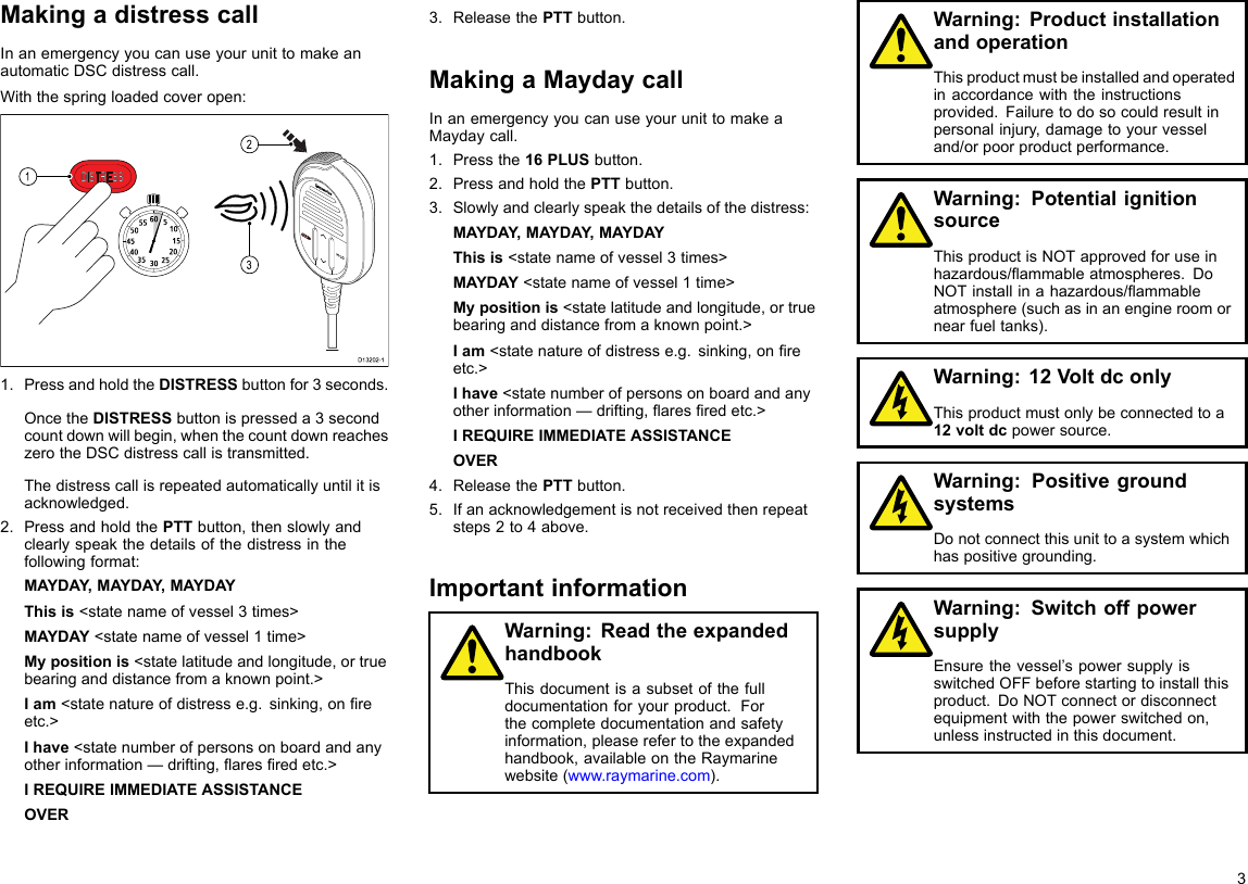
![Mypositionis<statelatitudeandlongitude,ortruebearinganddistancefromaknownpoint.>Iam<statenatureofdistresse.g.sinking,onreetc.>Ihave<statenumberofpersonsonboardandanyotherinformation—drifting,aresredetc.>IREQUIREIMMEDIATEASSISTANCEOVER3.ReleasethePTTbutton.MakingaMaydaycallInanemergencyyoucanuseyourunittomakeaMaydaycall.1.Pressthe16PLUSbutton.2.PressandholdthePTTbutton.3.Slowlyandclearlyspeakthedetailsofthedistress:MAYDAY,MAYDAY ,MAYDAYThisis<statenameofvessel3times>MAYDAY<statenameofvessel1time>Mypositionis<statelatitudeandlongitude,ortruebearinganddistancefromaknownpoint.>Iam<statenatureofdistresse.g.sinking,onreetc.>Ihave<statenumberofpersonsonboardandanyotherinformation—drifting,aresredetc.>IREQUIREIMMEDIATEASSISTANCEOVER4.ReleasethePTTbutton.5.Ifanacknowledgementisnotreceivedthenrepeatsteps2to4above.CancellingadistresscallbeforetransmissionTocanceladistresscallbeforeitistransmittedfollowthestepsbelow:1.ReleasetheDISTRESSbuttonbeforethecountdowntimercompletes.Whenthebuttonisreleasedyouwillbereturnedtonormaloperation.CancellingadistresscallaftertransmissionAdistresscallcanbecancelledafterithasbeentransmitted.D13229-141231.SelectOptions.2.SelectCanceldistress.3.SelectYestoconrmcancellation.4.SelectOK.5.PressandholdthePTTbuttonandmakeabroadcasttoallstationsgivingyourvessel’sname,callsignandMMSInumberandcancelthefalsedistressalertExample:“All,Stations,AllStations,AllStations.Thisis<NAME>,<CALLSIGN>,<MMSIID>,<POSITION>.Cancelmydistressalertof<DATE>,<TIME>,<NAME>,<CALLSIGN>”D13230-16.Repeatthebroadcastdescribedinstep5.ReceivingadistresscallItisexpectedthatonlyaCoastRadioStation(CRS)willacknowledgeDSCdistresscallsandwillactasthecoordinatorfortherescueoperation.WhenadistresscallisreceivedanalarmissoundedatfullvolumeandtheLCDdisplaysinformationrelatingtothedistress.DISTRESS CALLShow infoSinkingMMSI 12345678900:04Accept - Ch16 [10]22Ray50/Ray60/Ray70](https://usermanual.wiki/Flir-BelgiumBA/RAY60/User-Guide-2523170-Page-22.png)