Flow Numatics 2004 Control Valve 1505490996 User Manual
Numatics 2004 Control Valve-1505490996 NUMATICS_2004_CONTROL_VALVE-1505490996
2017-10-06
User Manual: Flow Numatics 2004 Control Valve-1505490996
Open the PDF directly: View PDF ![]() .
.
Page Count: 25
2004 Series
Solenoid Pilot Actuated Valves
www.numatics.com

Table of Contents
2004 Series
25 Pin Sub-D and Terminal Strip Options 3
Electronic Interface and I/O Module options 4
Technical Data 5
How to Order 6-8
Single Station Valve Manifold Assembly 9
FlexiBlok® Assembly 10-11
Sandwich Pressure Regulators 12
Valve Regulator / Speed Control Plug-in Assembly 13
Regulator Kits & Service Parts 13
Sandwich Pressure Regulator 14
Manifolds 15
Solenoid Assembly 16
Blank Station Plate Kit 16
Speed Control Kit 16
Mid-Station Supply and Exhaust Block 17
Sandwich Pressure Block 17
DIN Rail Clamp Kit 18
Blocking Discs 18
Internal Pilot Plug Assembly 18
End Plate Assembly Kit - Threaded Parts List 19
Sandwich Pressure Block Parts List 19
Sub-D Kit Parts List 20
Terminal Block Kit Parts List 20
Valve Service Kits and Parts 21-24
Information subject to change without notice. For ordering information or regarding your local sales office visit www.numatics.com.
3
2004
SERIES
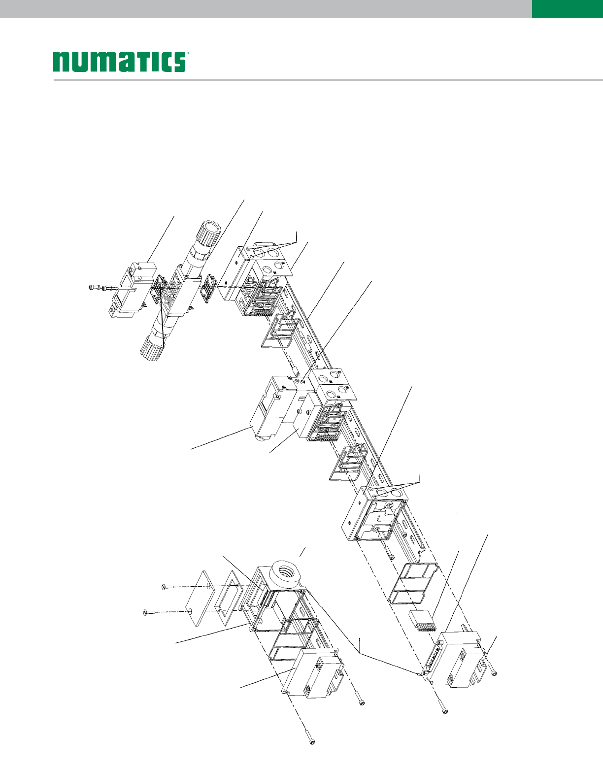
Blank Station
Plate
Left End
Mounting
Bracket
Assembly
DIN Rail
Mounting Clip
Terminal Strip
Housing Assembly
Can be used
interchangeably
Phoenix Quick
Connect
Terminal Strip
Speed Control
Assembly
External Pilot
Supply & Exhaust
Transfer Connector
25 Pin Sub-D Housing Assembly
Left End Mounting Bracket
Left End Plate Assembly
(Supply & Exhaust)
Plug-In
Manifold
Assembly
DIN Rail Compatible
2004 Direct Acting Single
Solenoid
Valve Unit
2004 Double Solenoid
Air Pilot Valve Unit
External Pilot
Supply &
Exhaust
Right End
Plate Assembly
(supply & exhaust)
Dual
Sandwich
Pressure
Regulator
(single regulator
also available)
1/2” Conduit
Connection
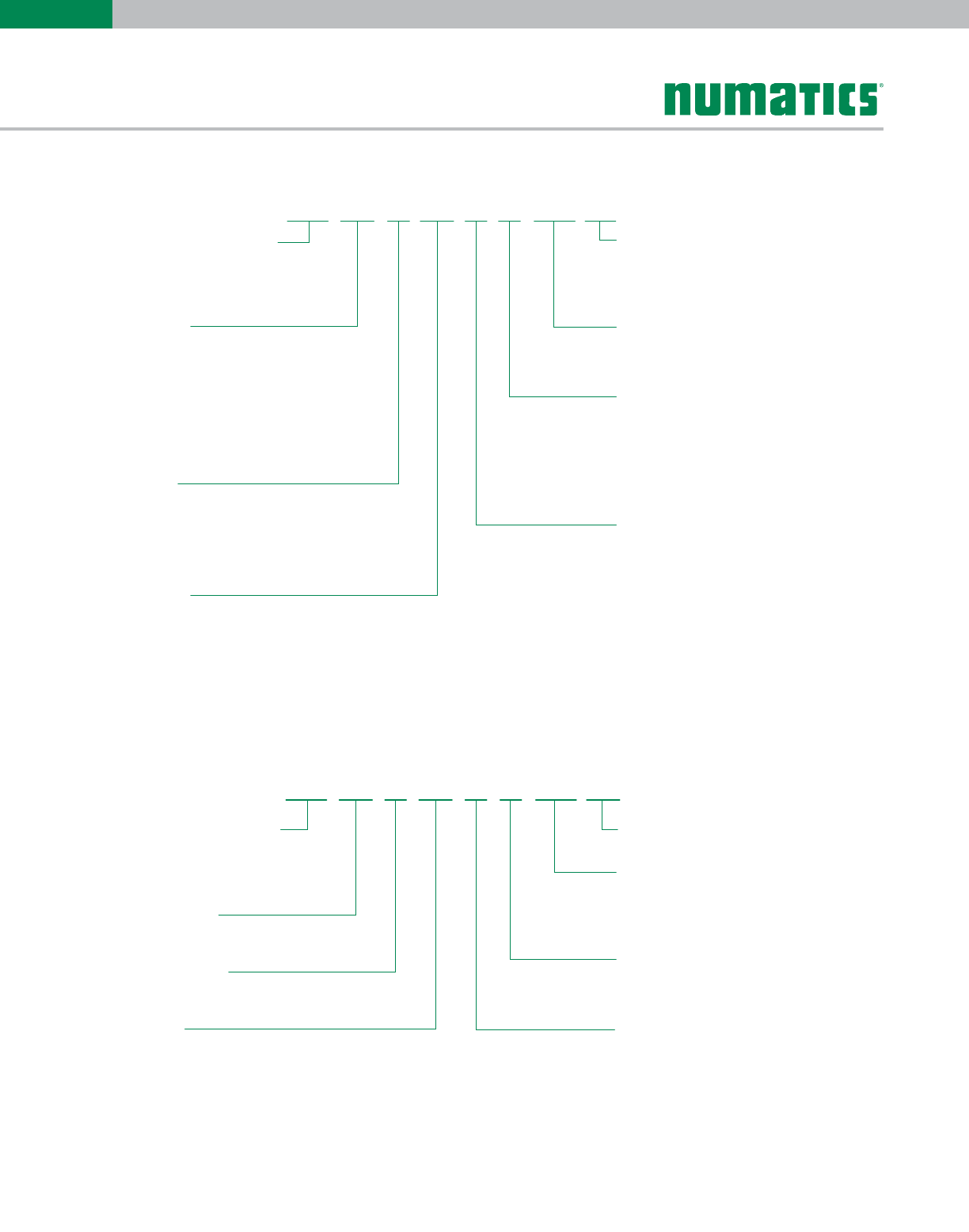
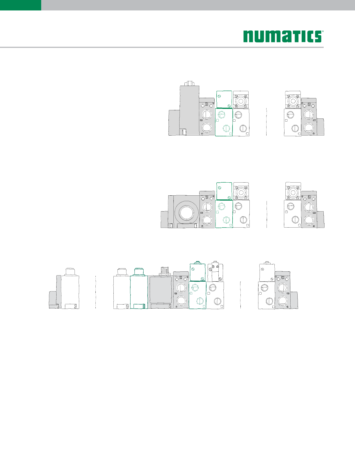
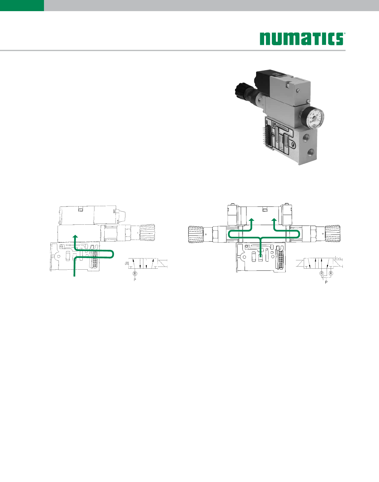
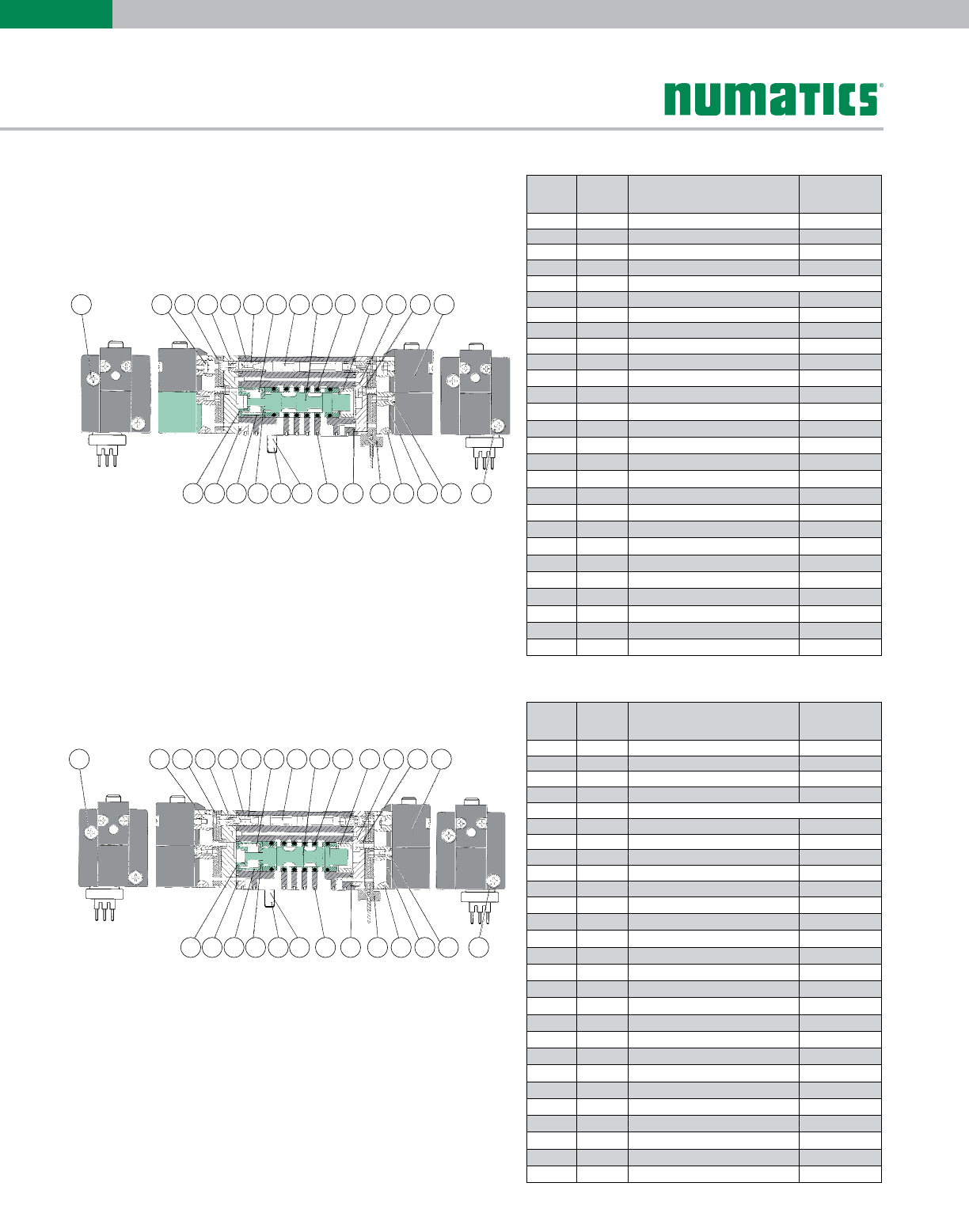
Manifold and Wiring Architecture
25 Pin Sub-D and Terminal Strip Options
(expanded view)
Sub-D Option
Terminal Strip Option
Information subject to change without notice. For ordering information or regarding your local sales office visit www.numatics.com.
4
2004
SERIES
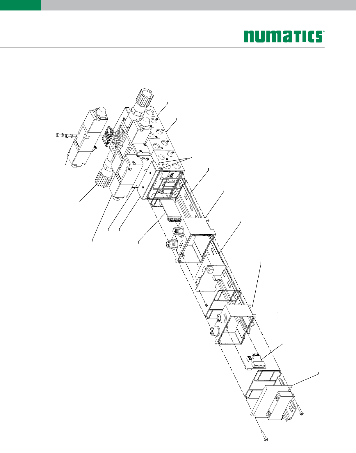
Manifold and Wiring Architecture
Electronic Interface and I/O Module options
(expanded view)
Direct Acting Single Solenoid Valve Unit
Dual Sandwich Pressure Regulator
(single regulator also available)
Left End Plate
Speed Control
Transfer Board
External Pilot Supply & Exhaust
DIN Rail Compatible
Electronic interface
Housing Assembly
Bus Electronic
Interface
Master I/O
Housing Assembly
Master I/O Electronic
Interface
Left End Mounting
Bracket Assembly
Plug-In Manifold
Assembly
Right End Plate
Direct acting double
solenoid valve unit
Information subject to change without notice. For ordering information or regarding your local sales office visit www.numatics.com.
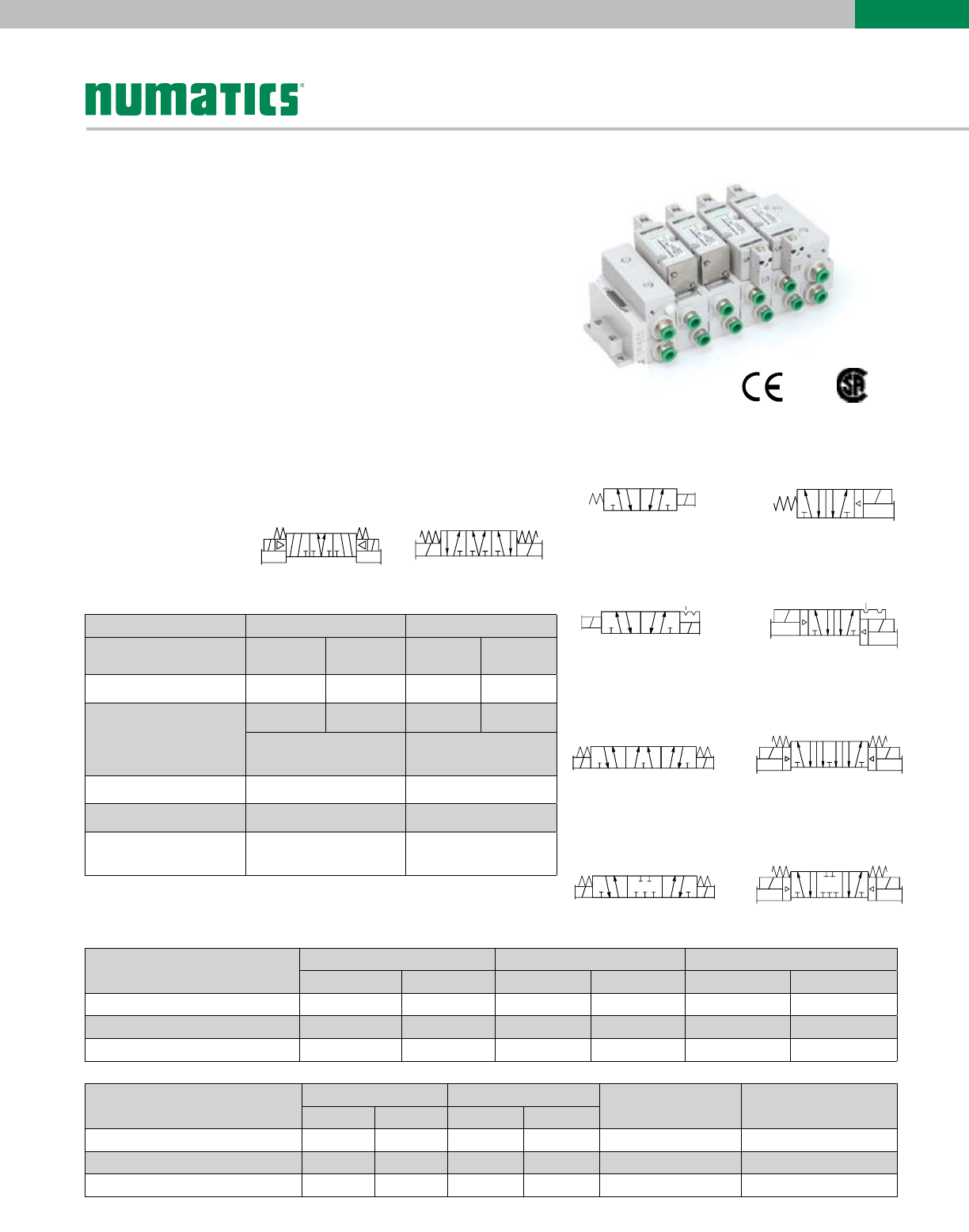
5
2004
SERIES
double solenoid pilot
3 Position 4-Way (5/3),
open to 4 (A) and
2 (B) in center
4 2
5 1 3
14 12
P
EB
EA
double solenoid
3 Position 4-Way (5/3),
open to 4 (A) and
2 (B) in center
(2)(4)
B A
A
(14)
B
(12)
(3) (1) (5)
• All internal wiring eliminated
• True plug together flexibility/expandability
• Designed to meet NEMA 4 specifications
• Compact plug together bus interface module
• 25 pin sub-D connector option
• Terminal strip option (Phoenix style)
• Plug together modular Inputs/Outputs
• Plug-in speed control sandwich with adjustments on
one side
• Plug-in single and dual pressure regulators
Valve Data NPTF G Tap
Direct Solenoid Air
Pilot
Direct Solenoid Air
Pilot
Cv 0.35 0.40 0.25 0.40
Flow Capacity 16 SCFM 18 SCFM 345 NI/m 394 IN/m
flow to atm @ 80 PSIG flow @ 6 Bar upstream &
5 Bar downstream
Operating Pressure Range: 28" Hg. to 150 PSIG Vacuum to 10 bar
Pilot Pressure Range 20 to 115 PSIG 2.5 to 8 bar
Temperature Range
(Ambient) -10˚F to +115˚F ambient -23˚C to +46˚C
(2) (4)
B A
(2) (4)
B A
EB PEA
(3)(1) (5)
EB PEA
(3)(1) (5)
(2) (4)
B A
(2) (4)
B A
EB PEAEB PEA
(3)(1) (5)
(2)(4)
B A
(2)(4)
B A
EBPEAEBPEA
(3)(1) (5)
(2) (4)
B A
(2)(4)
B A
A
(14)
A
(14)
B
(12)
A
(14)
B
(12)
A
(14)
A
(14)
B
(12)
A
(14)
B
(12)
B
(12)
A
(14)
B
(12)
B
(12)
A
(14)
B
(12)
EB PEA
(3) (1) (5) EB PEA
(3) (1) (5)
(2)(4)
(2)(4)
B A
EB PEA
(3) (1) (5)
(2)(4)
(2)(4)
B A
EB PEA
EB PEA
(3) (1) (5)
(2)(4)
(2)(4)
B A
EB PEA
EB PEA
(3) (1) (5)
double solenoid
3 position 4-way
open center
double solenoid air pilot
3 position 4 way
open center
double solenoid
3 position 4-way
closed center
double solenoid air pilot
3 position 4-way
closed center
single solenoid
2 position 4-way
single solenoid air pilot
2 position 4-way
double solenoid
2 position 4-way
double solenoid air pilot
2 position 4-way
Technical Data
Operating Data
All Solenoids Are Continuous Duty
Rated
24 VDC 12 VDC Direct Solenoid Only
Direct Solenoid Pilot Direct Solenoid Pilot 115 VAC/50Hz 120 VAC/60Hz
Power (Watts) 6.0W 0.5W 6.0W 0.5W 5.4 4.1
Holding Current (Amps.) 0.25 0.02 0.25 0.02 0.063 0.052
Inrush Current (Amps.) N/A N/A N/A N/A 0.093 0.090
Response Time in Seconds Energize De-Energize Energize De-Energize
Direct Sol. Pilot Direct Sol. Pilot
2-Position, Single, Spring Return 0.012 0.014 0.008 0.028 0.008 0.012
2-Position, Double, Detented 0.012 0.014 N/A N/A 0.008 N/A
3-Position, Spring Centered 0.012 0.014 0.008 0.028 0.008 0.012
Information subject to change without notice. For ordering information or regarding your local sales office visit www.numatics.com.
6
2004
SERIES
M041 BA Z1
Valve Series & Port Size
041 = 1/8
042 = 1/4
04D =4 mm (5/32)
04F =6 mm
Valve Type
BA = Single Solenoid Air Pilot w/Flush
Non-locking Override
BB = Double Solenoid Air Pilot w/Flush
Non-locking Override
SA = Single Solenoid w/Flush
Non-locking Override
SS = Double Solenoid w/Flush
00 = Manifold w/no Valve
Non-locking Override
Function
4 = 2 Position, 4-Way
5 = 3 Position, 4-Way Open Center
6 = 3 Position, 4-Way Blocked Center
7=3 Position 4-Way (5/3), Pressure Center
P=Indicates Blank Station Plate
Open to 4 (A) and 2 (B) in Center
Mounting
Z1 = Side and Bottom Ports,
Single Solenoid Z-Board
Z2 = Side and Bottom Ports,
00 =Valve Unit Only
Double Solenoid Z-Board
Z3 = Side Ports only, Single Solenoid Z-Board
Z4 = Side Ports only, Double Solenoid Z-Board
Z5 = Z1 with Speed Control
Z6 = Z2 with Speed Control
Z7 = Z3 with Speed Control
Z8 = Z4 with Speed Control
Voltage
20 = 24/50 - 60 VAC
30 = 110-120/50-60 VAC
60 = 12 VDC
61 = 24 VDC
Options
000 = Standard
11B = Flush Locking Override
14X = External Pilot
Port Type
G = G Tap (AC)
K= Push-in Fitting (DC)
L= Push-in Fitting (AC)
N = NPTF (AC)
P= NPTF or Valve Unit Only (DC)
Q= G Tap (DC)
0=
=
=
=
=
=Valve Unit Only (AC)
Wiring Option
K = Plug-in AC w/Light
M = Plug-in DC w/Light
4P000 61
J041 RS Z1
Valve Series & Port Size
041 = 1/8
042 = 1/4
04D =4 mm (5/32)
04F =6 mm
Regulator Type
RS = Single Pressure to Port P (1)
RD = Dual Pressure to Ports EB (3) & EA (5)
Pressure Range
3 = 3-30 PSIG Regulator
7=0-100 PSIG Regulator
Mounting
Z1 = Side and Bottom Ports,
Single Solenoid Z-Board
Z2 = Side and Bottom Ports,
00 = Regulator Unit Only
Double Solenoid Z-Board
Z3 = Side Ports only, Single Solenoid Z-Board
Z4 = Side Ports only, Double Solenoid Z-Board
Z5 = Z1 with Speed Control
Z6 = Z2 with Speed Control
Z7 = Z3 with Speed Control
Z8 = Z4 with Speed Control
Voltage
00 = Not Applicable
Options
000 = Standard
14X = External Pilot
16N = Jumper on 14 End
16P = Jumper on 12 End
Port Type
G =G Tap
L=Push-in Fitting
N = NPTF
Wiring Option
J = Plug-in Receptacle Assembly
3N000 00
How to Order

Information subject to change without notice. For ordering information or regarding your local sales office visit www.numatics.com.
7
2004
SERIES
DRM0000AK
Electrical/Electronics
Type & Location
F = Terminal Strip
J = 25 Pin Sub-D
C= Fieldbus Electronics,
See Electronics Section
Valve Line
D = 2004 Series
*Number of Va lve Stations
A1 =9
B2 = 10
C3 =11
D4 =12
E5 =13
F6 =14
G7 =15
H
=
=
=
=
=
=
=
=8
I
J
K
L
M
N
O
P=16
Options
STD = Standard
DRM = DIN Rail Mounting (Std .35mm)
MUF = Muffler in End Plates
DWM = DIN Rail with MUF
Port Type
GG Tap
L Push-In
N
=
=
= NPTF
End Plate Port Size
2 1/4
F6 mm (Push-In only)
H
=
=
= 8mm (Push-In only)
DFH 2L
The electrical connection type.
– Sub-D (AK“J”) 16 maximum solenoid outputs
– Terminal Strip (AK“F”) 16 maximum solenoid outputs
How to Order
Manifold Assembly
Information subject to change without notice. For ordering information or regarding your local sales office visit www.numatics.com.
8
2004
SERIES
• Shaded components described by Assembly Kit (AK)
model number designation (see electronics section), with
the exception of the Serial/Bus module and number of I/O
stations that are described by Electronic Interface (NXD)
model number designation. (see electronics section)
• Each valve manifold station is listed in sequential order
from left to right when facing the port side of the manifold
as indicated.
• Each discrete I/O station is listed in sequential order from
RIGHT to LEFT starting from the Serial/Bus module as
indicated.
Example order:
AKCDD0000HLSTD
valve station 1 042BA4Z3MK00061
valve station 2 042BA4Z3MK00061
valve station 3 042BB4Z4MK00061
valve station 4 042BB4Z4MK00061
NXDDN0808DFE02
I/O station 1 239-1802 Input Master Kit
I/O station 2 239-1803 Input Slave Kit
I/O station 3 239-1803 Input Slave Kit
I/O station 4 239-1803 Input Slave Kit
I/O station 5 239-1800 Output Master Kit
I/O station 6 239-1801 Output Slave Kit
I/O station 7 239-1801 Output Slave Kit
I/O station 8 239-1801 Output Slave Kit
ASSEMBLED
NOTE: I/O station #1 must always be a MASTER KIT (see electronics section).
NOTE: Total of 16 solenoid outputs available. Either 16 single solenoid valves or 8 double solenoid valves or any combination of singles or doubles,
not to exceed 16 solenoid outputs.
valve
stations:
I/O
stations:
Serial Bus
Module NXD
1 2 ....... 16
{
{
2 1
{
{
{
{
{
.......8
{
{
{
valve
stations: 1 2 ....... 16
{
{
{
{
{
valve
stations: 1 2 ....... 16
{
{
{
{
{
Manifold Assembly Example
AKJ 25 Pin Sub-D
• Shaded components described by Assembly Kit
(AK) model number designation (pg. 7).
• Each valve manifold station is listed in sequential
order from left to right when facing the port side of
the manifold as indicated.
Example Order:
AKJDD00002NSTD
valve station 1 042SA4Z3KL00030
valve station 2 042SA4Z3KL00030
valve station 3 042SS4Z4KL00030
valve station 4 042SS4Z4KL00030
ASSEMBLED
AKF Terminal Strip
• Ordered using the same method as for 25 Pin
Sub-D
Example Order:
AKFDD0000FLSTD
valve station 1 042SA4Z4KL00030
valve station 2 042SA4Z4KL00030
valve station 3 042SS4Z4KL00030
valve station 4 042SS4Z4KL00030
ASSEMBLED
AKC Serial/Bus
Information subject to change without notice. For ordering information or regarding your local sales office visit www.numatics.com.
9
2004
SERIES
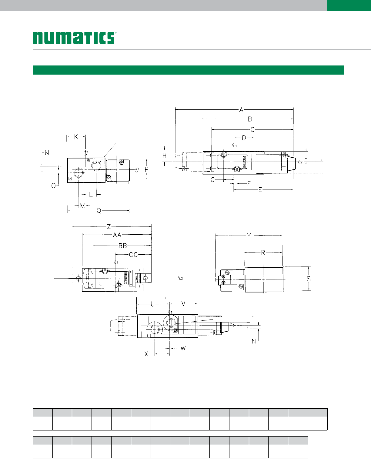
SOLENOID AIR PILOT
Port Options:
1/8 NPTF, 1/8 push-in,
5/32 (4mm) push-in,
1/4 push-in
1/8 NPTF
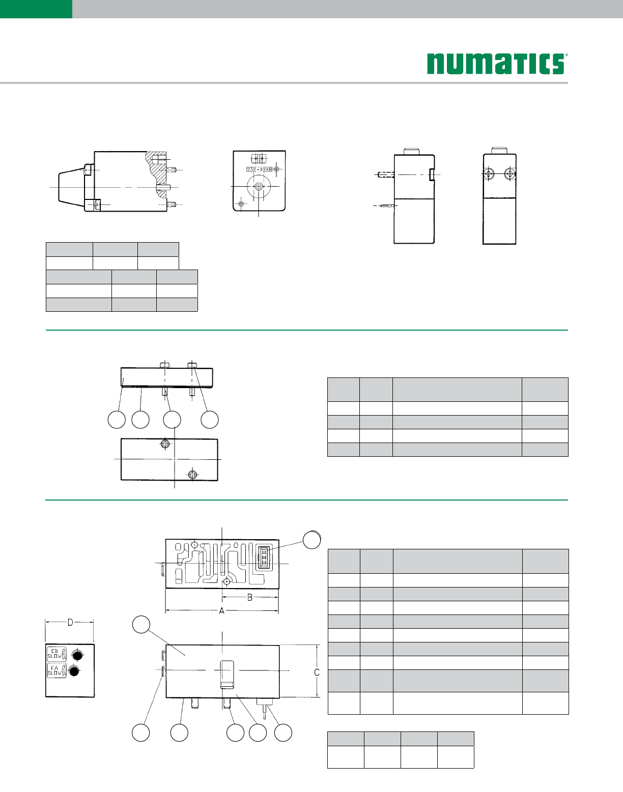
Single Station valve Manifold Assembly
direct solenoid and solenoid air pilot
Dimensions: Inches (mm)
A B C D E F G H I J K L M N O
5.10
(129.6)
3.98
(101.2)
3.52
(89.3)
0.87
(22.0)
2.55
(64.8)
0.13
(3.4)
0.44
(11.3)
0.52
(13.1)
0.48
(12.3)
0.44
(11.1)
0.78
(19.8)
0.43
(11.0)
0.30
(7.6)
0.16
(4.0)
0.13
(3.2)
P Q R S T U V W X Y Z AA BB CC
0.88
(22.2)
2.57
(65.3)
1.56
(39.7)
1.00
(25.4)
2.64
(67.0)
1.43
(36.4)
1.21
(30.6)
0.06
(1.6)
0.65
(16.4)
2.75
(69.9)
3.45
(87.6)
3.22
(81.6)
2.55
(64.8)
1.58
(40.1)

Information subject to change without notice. For ordering information or regarding your local sales office visit www.numatics.com.
10
2004
SERIES
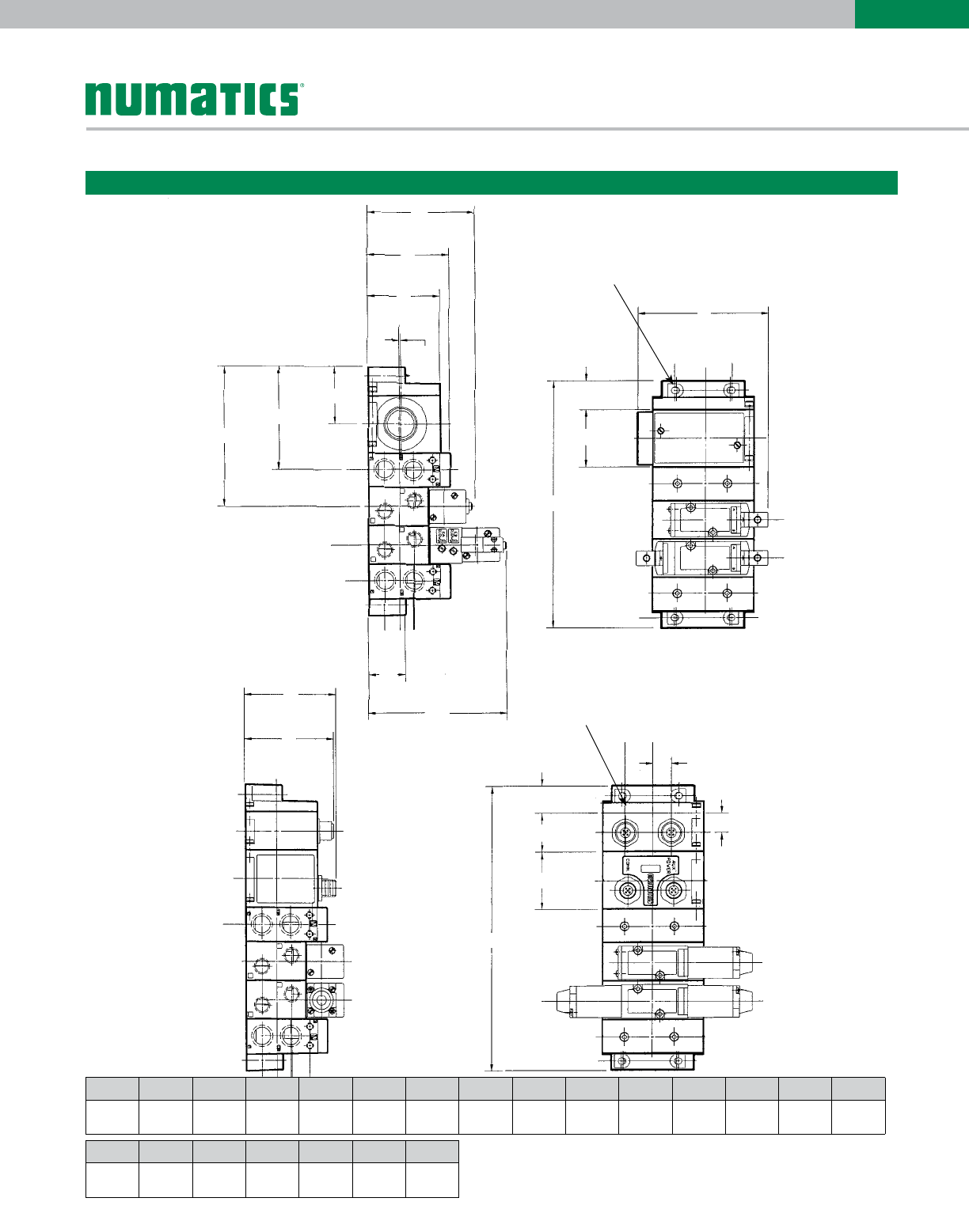
1/4 NPTF or 8mm &
1/4 push-in fittings
(4 places)
1/8 NPTF
Port Options: 1/8 NPTF, 1/8 push-in,
5/32 (4mm) push-in, 1/4 push-in
#10-32 TAP
(4 Places)
Clearance for M4 Screw
4 places
Clearance for M4 Screw
4 places
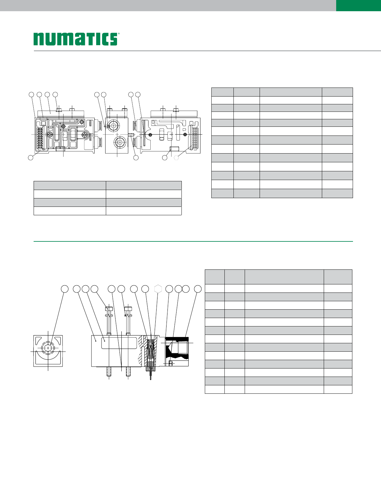
FlexiBlok® Assembly
25 pin sub-D Housing Assembly
Dimensions: Inches (mm)
A B C D E F G H I J K L M N O
1.21
(30.6)
1.43
(36.4)
0.86
(21.8)
0.83
(21.1)
0.36
(9.1)
0.39
(9.9)
1.88
(47.8)
1.62
(41.2)
2.58
(65.5)
0.44
(11.2)
0.25
(6.2)
0.96
(24.4)
2.13
(54.1)
3.51
(89.2)
2.64
(67.0)
Q R S T U V W
1.33
(33.7)
0.87
(22.2)
1.50
(38.1)
0.63
(15.9)
0.25
(6.5)
0.88
(22.4)
1.18
(30.0)
Information subject to change without notice. For ordering information or regarding your local sales office visit www.numatics.com.
11
2004
SERIES
TERMINAL STRIP
HOUSING ASSEMBLY
E
Clearance for M4 Screw
4 Places
U
V
F
G
H
I
J
K
A
B
C
D
P
Q
R
S
N
O
T
M
L
Clearance for M4 Screw
4 Places
FlexiBlok® Assembly
Bus Electronic Interface
I/O Housing Assembly
Dimensions: Inches (mm)
P Q R S T U V
0.71
(18.1)
1.00
(25.4)
1.50
(38.1)
7.42
(188.5)
0.50
(12.7)
2.38
(60.5)
2.32
(59.0)
A B C D E F G H I J K L M N O
3.41
(86.6)
0.75
(19.1)
1.50
(38.1)
6.46
(164.1)
2.81
(71.4)
2.13
(54.1)
1.88
(47.8)
0.06
(1.6)
1.50
(38.1)
2.69
(68.3)
3.65
(92.7)
0.96
(24.4)
3.61
(91.7)
0.73
(18.5)
0.49
(12.5)
Information subject to change without notice. For ordering information or regarding your local sales office visit www.numatics.com.
12
2004
SERIES
P
SUPPLY
P
P
SUPPLY
EB EA
Single pressure from a single supply. Dual pressure from a single supply.
Sandwich Pressure Regulators
Types: RS / RD
When ordering a valve plus regulator mounted on a manifold, list the
valve unit-only model number and include the mounting requirements
within the regulator model selection. Specify “Assembled.”
Example orders: TYPE RS TYPE RD
Valve unit only: 041SA407K000030 (AC) 041BB407MP00061 (DC)
Regulator 041RS3Z1JN000000 041RD3Z2JN000000
+ mounting ASSEMBLED ASSEMBLED
Type RS Type RD
Information subject to change without notice. For ordering information or regarding your local sales office visit www.numatics.com.
13
2004
SERIES
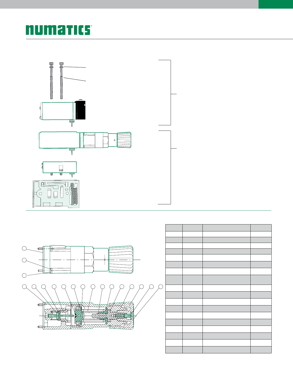
Valve Regulator / Speed Control Plug-in Assembly
041BA407MP00061
2004 single solenoid valve unit with
plug-in assembly and extra long mount-
ing screws for use with
regulator and speed control
042RS3Z7JL00000
Single pressure regulator Type RS +
speed control sandwich mounted on a
1/4 inch manifold with side ports and
push-in fittings.
lockwasher (2)
#128-192
screw (2)
#127-798
EXAMPLE
Example order:
Valve: 041BA400M000061
Regulator: 042RS3Z7JL00000
ASSEMBLED
Regulator Kits & Service Parts
Regulator Service Kit 239-708
123456710 11 12 13 14 15
16
17
18
88
Parts List
* (2) Required for RD
** (8) Required for RD
Det. No. No. Req'd Part Name Part No.
1 1 Regulator Body 101-706
2* 1 Spring 115-226
3* 1Poppet Assembly 221-168
4 1 Poppet Seat 124-148
5* 1 O-Ring 126-336
6* 1Seal U-Packing 124-383
7 1 Piston 125-618
8 1 Spring 0-30 PSIG
0-100 PSIG
115-352
115-342
9 1 Metering Screw 118-187
10 1Spring Guide 112-369
11* 1 Bearing 125-617
12 1 Bonnet 125-623
13 1 Knob 125-624
14* 1 Screw 127-706
15 1 Label 122-992
16* 1 Gasket 113-472
17 4 Screw 127-380
18 4 Lockwasher 128-172
Information subject to change without notice. For ordering information or regarding your local sales office visit www.numatics.com.
14
2004
SERIES
36
4
9
25
1
A
B
C
E
D
7
8
36
4
9
25
1
A
B
C
E
D
7
8
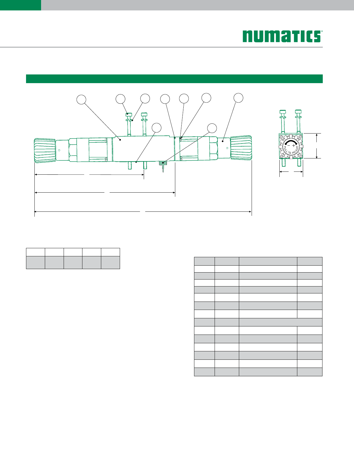
* (1) Required for RS
** (4) Required for RS
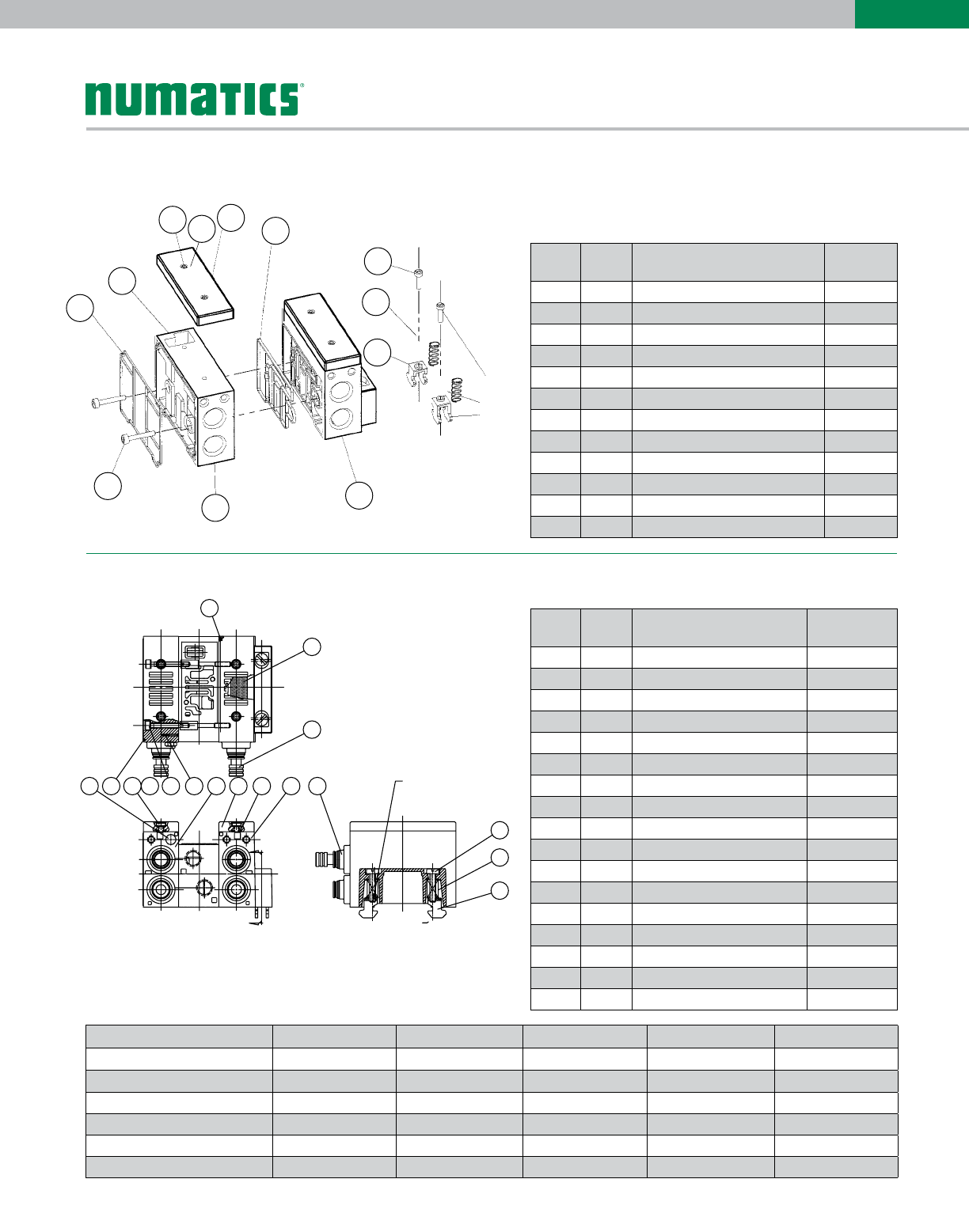
Sandwich Pressure Regulator
Dimensions: Inches (mm)
A B C D E
4.08
(103.7)
5.24
(133.0)
8.17
(207.4)
0.94
(23.9)
0.87
(22.1)
Parts List
Det. No. No. Req'd Part Name Part No.
1 1 Regulator Block (RD) 125-716
1 1 Regulator Block (RD) 125-715
2 2 Regulator Block (RD) 127-798
3 2 Lockwasher 128-192
4* 2 Gasket 113-472
5** 8 Lockwasher 128-172
6** 8 Screw 127-380
7** 2Regulator Assembly (not sold separately)
8 1 J Plug Board Encap. 230-835
9 1 Gasket 113-499
not shown 1Retaining Shroud 125-717
not shown 1 Shroud 125-718
Pressure Gauge 0-150 PSIG 214-209
Pressure Gauge 0-60 PSIG 214-216
Information subject to change without notice. For ordering information or regarding your local sales office visit www.numatics.com.
15
2004
SERIES
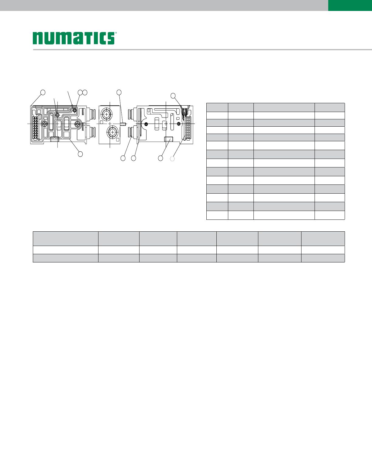
Manifolds
Stud
#127-792
PORT N
PORT X
B
A
124
5
6
7
3
9
10
8
NOTE: For direct acting applications, factory will install plug into the N-port.
For SPA applications, factory will install plug into the X-port.
For manifolds ordered individually, pilot plugs will be packaged separately.
If using internal pilot supply (Port N), the X-port in the left end plate must be plugged.
Parts List
Det. No. No. Req'd Part Name Part No.
1 1 Manifold not sold separately
2 1 Blocking Disk 125-730
3 1 O'Ring Seal 126-427
4 2 Stud 127-792
5 1 Retaining Shroud 125-717
6 1 Manifold Board ASS'Y not sold separately
7 1 Pipe Plug (1/8 NPTF) 129-100
8 1 Fitting Clip 125-1136
9 2 1/4 Slip-In Cartridge 134-518
1/8 Slip-In Cartridge 134-500
4MM Slip-In Cartridge 134-498
8MM Slip-In Cartridge 134-499
10 1 Gasket 113-504
Manifold Assembly Kits 1/8 NPTF G 1/8 1/8 Push-In 5/32 - 4mm
Push-In 1/4 Push-In 6mm Push-In
Single “Z-Board”™ 239-935 239-1036 239-2346 239-2348 239-2345 239-2347
Double “Z-Board”™ 239-934 239-1035 239-2350 239-2352 239-2349 239-2351
Information subject to change without notice. For ordering information or regarding your local sales office visit www.numatics.com.
16
2004
SERIES
Solenoid Assembly
Direct Solenoid Solenoid Air Pilot 236-565
VDC 2 Pos. 3 Pos.
24 236-319 236-337
VDC 2 Pos. 3 Pos.
110-120/50-60 237-1018 237-1015
24/50-60 237-1019 237-1017
1 2 3 4
Det.
No.
No.
Req'd Part Name Part No.
1 1 Blank Station Plate 104-638
2 1 Gasket 113-505
3 2 Screw 127-536
4 2 Lockwasher 128-192
Blank Station Plate Kit
239-915 Parts List
7
1
6 5 3 4 2
Parts List
Speed Control Kit
239-916
Det.
No.
No.
Req'd Part Name Part No.
1 1 Speed Control (not sold separately)
2 1 J Plug Board Encap. 230-835
3 2 Screw 127-795
4 2 Lockwasher 128-192
5 1 Gasket 113-499
6 2 Metering Screw 118-198
7 1 Retaining Screw 125-717
not
shown 1 Shroud 125-718
not
shown 2Nylon Rod (for metering screw) 125-259
A B C D
2.04
(51.8)
1.02
(25.9)
0.94
(23.8)
0.87
(22.1)
Information subject to change without notice. For ordering information or regarding your local sales office visit www.numatics.com.
17
2004
SERIES
P
E
1
9101112
65
23
47
8
Mid-Station Supply and Exhaust Block
234 5789 13
61
011121
Sandwich Pressure Block
239-2519
1/8 NPTF Det.
No.
No.
Req'd Part Name Part No.
1 1 Pipe Plug 129-100
2 1 Riser Block 125-715
3 1 Nameplate 122-242
4 2 Screw 127-798
5 1 Gasket 113-499
6 2 Lockwasher 128-192
7 1 Retaining Shroud 125-717
8 1 Shroud 125-718
9 1 J Plug Board Encap. 230-835
10 1 Gasket 113-290
11 4 Screw 127-260
12 4 Lockwasher 128-172
13 1 Adapter 119-737
Parts List
Det. No. No. Req'd Part Name Part No.
1 1 Mid Station Plate 125-1143
2 1 Gasket 113-505
3 1 Blank Station Plate 104-638
4 2 Screw Ass'Y 127-570
5 1 Blocking Plug 125-730
6 1 O-Ring 126-427
7 2 Tube Cartridge 134-499
8 1 Fitting Clip 125-1136
9 1 Transfer Board Ass'Y 256-717
10 1Pipe Plug 129-100
11 2 Stud 127-792
12 1 Gasket 113-504
Port Type Part. No.
1/8 239-1419
G 1/8 239-1616
6mm Push-in 239-2344
Information subject to change without notice. For ordering information or regarding your local sales office visit www.numatics.com.
18
2004
SERIES
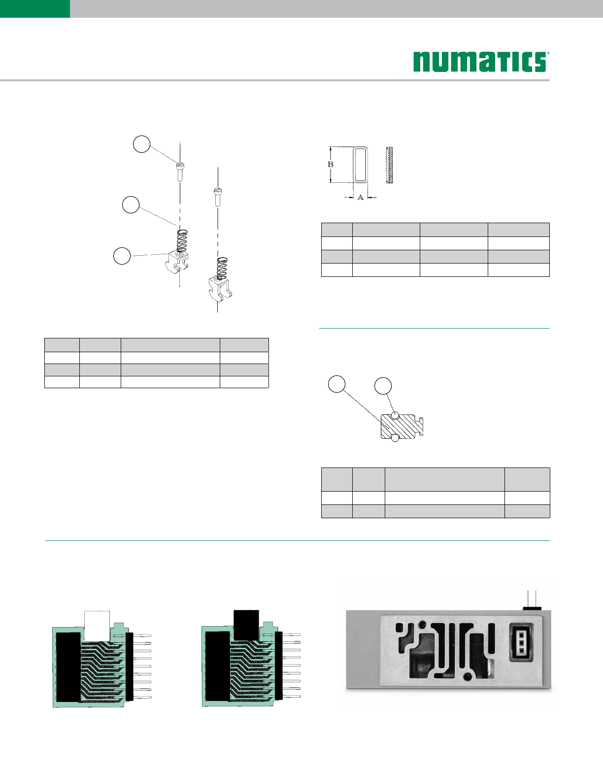
DIN Rail Clamp Kit 239-980 Blocking Discs
“Z-Boards”™
white black
Plug color visible from top of manifold block.
Double Single
Internal Pilot Plug Assembly 213-492
1
2
3
12
Parts List
Det. No. No. Req'd Part Name Part No.
1 4 Screw 127-472
2 4 Spring 115-355
3 4 Clamp 125-720
Parts List
Det.
No.
No.
Req'd Part Name Part No.
1 1 Blocking Plug 125-730
2 1 O-Ring 126-427
Port Part No. A B
P124-307 0.27 0.70
EA 124-308 0.19 0.73
EB 124-309 0.24 0.54
Information subject to change without notice. For ordering information or regarding your local sales office visit www.numatics.com.
19
2004
SERIES
End Plate Assembly Kit - Threaded
DIN
rail
option
only
End Plate Assembly Kit - Push-In
B
A
PLT
EXH
PLT
EXH
EXH
P
P
EXH
12
13
14
15
1235 78 9106411
16
17
10
11
12
9
8
7
1
2
3456Parts List
Parts List
Det.
No.
No.
Req'd Part Name Part No.
1 1 Gasket 113-503
2 2 Gasket 113-500
3 4 Screw 127-795
4 4 Lockwasher 128-192
5 2 End Plate Cover 105-377
6 1 Gasket 113-504
7 2 Screw Assembly 127-563
8 1 LH End Plate See Chart
9 1 RH End Plate See Chart
10 2 Screw 127-472
11 2 Spring 115-355
12 2 Clamp 125-720
Det.
No.
No.
Req'd Part Name Part No.
1 1 Plug 129-138
2 1 Gasket 113-503
3 4 Screw 127-795
4 4 Lockwasher 128-192
5 2 Screw Ass'y 127-563
6 2 Retaining Clip 125-1137
7 1 LH End Plate 104-813
8 2 End Plate Cover 105-412
9 2 Gasket 113-500
10 1 RH End Plate 104-814
11 4 1/4 Fitting Cartridge 134-502
12 2 Screw 127-472
13 2 Spring 115-355
14 2 Clamp 125-720
15 1 Gasket 113-504
16 2 Muffler 125-846
17 2 Plug IN118-104-000
Fitting Type 1/4 NPTF ISO228/1-G1/4 1/4 Push-In 6mm Push-In 8mm Push-In
LH End Plate 104-610 104-633 104-813 104-813 104-813
RH End Plate 104-611 104-631 104-814 104-814 104-814
Kit Number without DIN Rail 239-943 239-945 239-2338 239-2336 239-2340
Kit Number with DIN Rail 239-950 239-952 239-2337 239-2335 239-2339
Kit Number with Muffler N/A N/A 239-2360 239-2359 239-2361
Kit Number with Muffler & DIN Rail N/A N/A 239-2363 239-2362 239-2364
Information subject to change without notice. For ordering information or regarding your local sales office visit www.numatics.com.
20
2004
SERIES
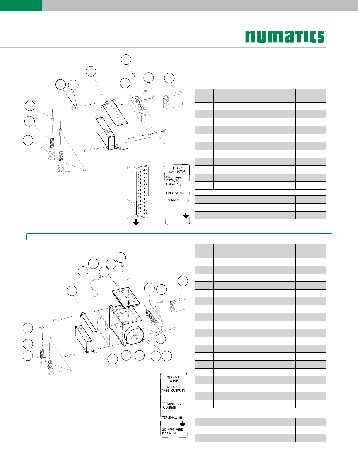
Sub-D Kit
Terminal Block Kit
DIN rail option only
SUB-D CONNECTOR
SHELL SIZE 3 25 POSITION
PINS 1-16
OUTPUTS
PINS 23-24
COMMON
PIN 25
EARTH
GROUND
PIN 25
EARTH
GROUND
EARTH
GROUND
DIN rail
option only
11
10
9
78
1
3
5
42
10
11
12
7
14
98
1513
2
6
5
4
3
1
17
18
19
Parts List
Parts List
Det.
No.
No.
Req'd Part Name Part No.
1 1 LH DIN Rail Mtg. Cover 105-381
2 1 Gasket 113-503
3 1 Cover Strap 125-772
4 1 Stick Screw 127-180
5 1 Cover 105-384
6 1 Gasket 113-508
7 2 Screw 127-826
8 4 Screw 127-795
9 6 Lockwasher 128-192
10 1 Transfer Connector 140-672
11 3 Screw 127-794
12 1 Terminal Strip Board 256-560
13 1 Housing 125-765
14 1 Gasket 113-509
15 1 Adaptor 1/2" NPTF 119-598
16* 2 Adaptor Mtg. Screw 127-827
17 2 Screw 127-472
18 2 Spring 115-355
19 2 Clamp 125-720
Det.
No.
No.
Req'd Part Name Part No.
1 1 Housing 105-379
2 1 Transfer Connector 140-672
3 2 Hex Screw 127-825
4 1 Gasket 113-507
5 2 Screw 127-794
6 1 Sub-D Board Assembly 256-532
7 2 Screw 127-499
8 2 Lockwasher 128-192
9 2 Screw 127-472
10 2 Spring 115-355
11 2 Clamp 125-720
Sub-D Housing Kits Part No.
With DIN Rail 239-1023
Without DIN Rail 239-1022
Sub-D Housing Kits Part No.
With DIN Rail 239-972
Without DIN Rail 239-968
* Indicates parts included in kit.
Information subject to change without notice. For ordering information or regarding your local sales office visit www.numatics.com.
21
2004
SERIES
2 3 5 6
9 10 12 13 14 11
1 4 7 8
15
1 2 3 5 6
4
7 8 9 10 12 13 14 11 15 16
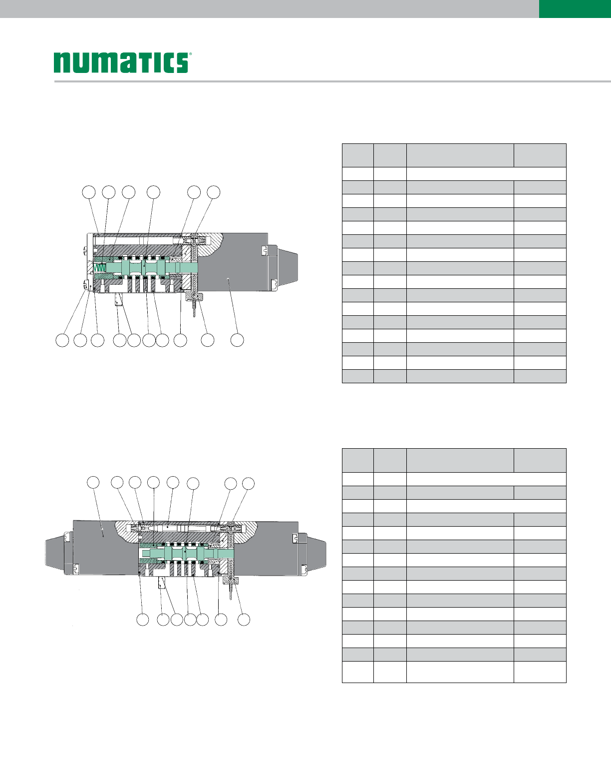
Valve Service Kits and Parts
Direct Acting
Kit No. MK4-K1*
(For Models 041SA4, 042SA4, 04DSA4)
Kit No. MK4-K1*
(For Models 041SS4, 042SS4, 04DSS4)
* Indicates parts included in kit.
* Indicates parts included in kit.
Parts List
Parts List
Det.
No.
No.
Req'd Part Name Part No.
1 1 Valve Body (not sold separately)
2* 1 Spring 115-203
3* 1 Bumper 114-183
4 1 Sleeve Assembly with Seals 209-547
5* 1 Detent Body 110-109
6 1 Spacer 116-496
7 2 Screw 127-797
8 1 Spring Cover 104-609
9* 1 Gasket 113-502
10 2 Screw 127-797
11 2 Lockwasher 128-192
12* 6 Seal 126-133
13* 1 Gasket 113-499
14* 1 Gasket 113-501
15 1 Solenoid Board Encap. 230-1134
16 1 Solenoid Capsule
Det.
No.
No.
Req'd Part Name Part No.
1 2 Solenoid Capsule
2 1 Duck Bill Housing 125-719
3 1 Valve Body (not sold separately)
4* 1 Bumper 114-183
5 1 A-B Recept. Encap. 230-834
6 1 Sleeve Assembly with Seals 209-547
7* 1 Detent Body 210-111
8 1 Spacer 116-496
9* 1 Gasket 113-502
10 2 Screw 127-797
11 2 Lockwasher 128-192
12* 6 Seal 126-133
13* 1 Gasket 113-499
14* 1 Gasket 113-501
14 1 Solenoid Board Encap. 230-1134
Information subject to change without notice. For ordering information or regarding your local sales office visit www.numatics.com.
22
2004
SERIES
2 3 47 8
9 10 12 13 14
11 15 16 17
15 6
18
2 3 47 8
9 10 12 13 1411 15 16 17
15 6
18
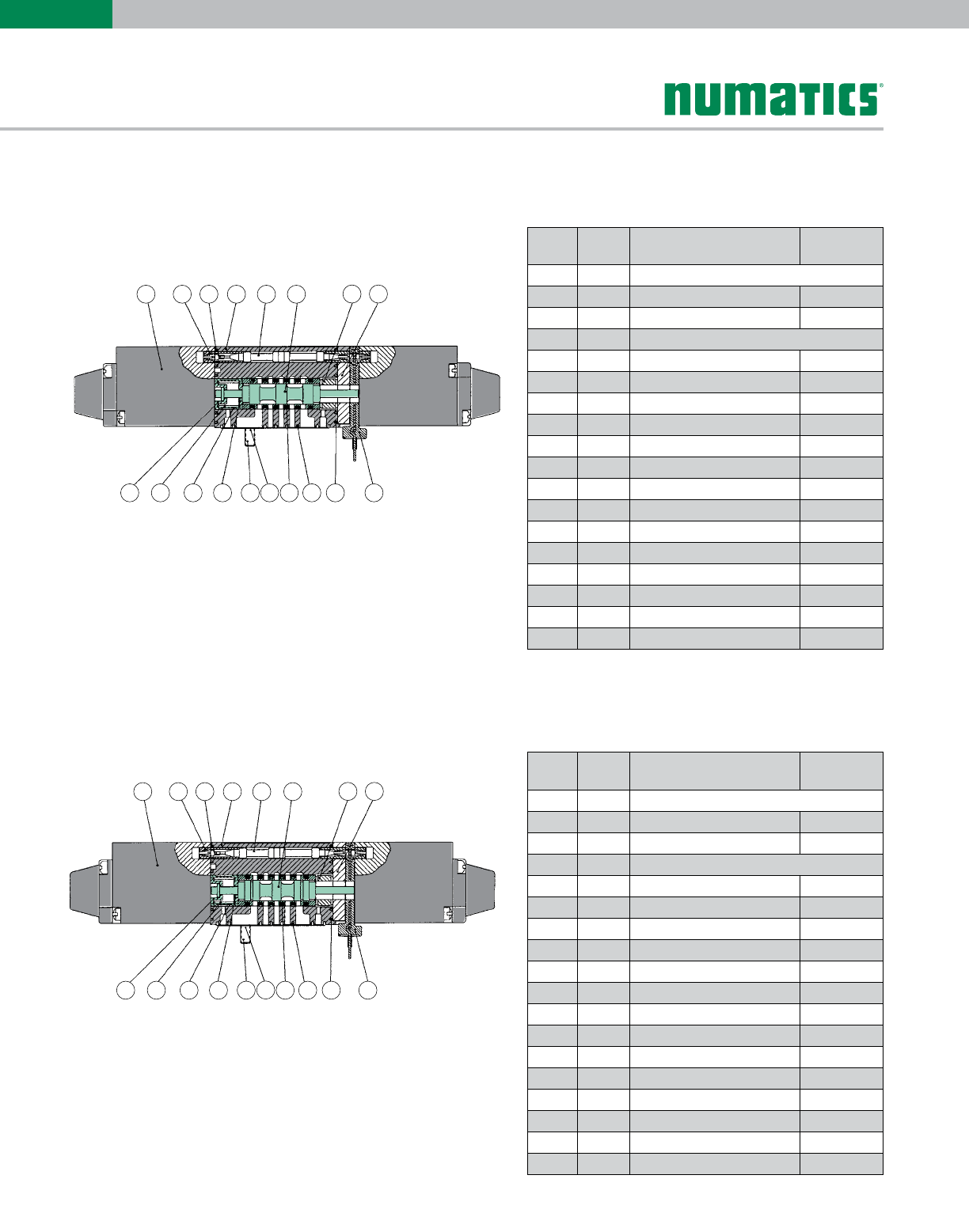
Valve Service Kits and Parts
Direct Acting
Kit No. MK4-K3*
(For Models 041SS5, 042SS5, 04DSS5)
Kit No. MK4-K3*
(For Models 041SS6, 042SS6, 04DSS6)
Parts List
Parts List
Det.
No.
No.
Req'd Part Name Part No.
1 2 Solenoid Capsule
2 1 Duck Bill Housing 125-719
3* 1* Gasket 113-502
4 1 Valve Body (not sold separately)
5 1 A-B Recept. Encap. 230-834
6 1 Sleeve Assembly with Seals 209-548
7* 1 Bumper 114-171
8 1 Spacer 116-496
9* 1 Spring Retainer 116-396
10 1 Spring 115-291
11* 1 Spacer 116-397
12* 1 Spring Retainer 116-395
13 2 Screw 127-797
14 2 Lockwasher 128-192
15* 6 Seals 126-133
16* 1 Gasket 113-499
17* 1 Gasket 113-501
18 1 Solenoid Board Encap. 230-1134
Det.
No.
No.
Req'd Part Name Part No.
1 2 Solenoid Capsule
2 1 Duck Bill Housing 125-719
3* 1 Gasket 113-502
4 1 Valve Body (not sold separately)
5 1 A-B Recept. Encap. 230-834
6 1 Sleeve Assembly with Seals 209-549
7* 1 Bumper 114-171
8 1 Spacer 116-496
9* 1 Spring Retainer 116-396
10* 1 Spring 115-291
11* 1 Spacer 116-397
12* 1 Spring Retainer 116-395
13 2 Screw 127-797
14 2 Lockwasher 128-192
15* 6 Seals 126-133
16* 1 Gasket 113-499
17* 1 Gasket 113-501
18 1 Solenoid Board Encap. 230-1134
* Indicates parts included in kit.
* Indicates parts included in kit.
Information subject to change without notice. For ordering information or regarding your local sales office visit www.numatics.com.
23
2004
SERIES
12 73 5 6
11 12 19 22
89
13 14 15 16 17 20 21
18
10
4
12 73 5 6
11 12 19 22
89
13 14 15 16 17 20 21
18
10
4
1
16 17 18
2 74 5 6 10 12 13
15 19 21 22 23 24
38911 14
20
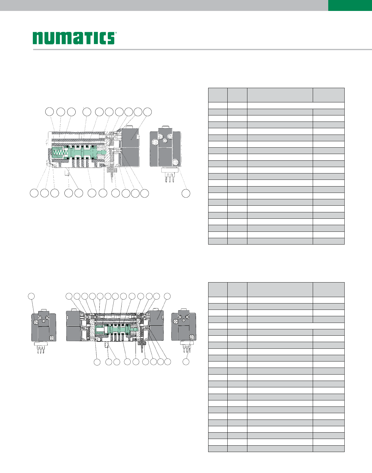
Valve Service Kits and Parts
Solenoid Air Pilot
Kit No. SPA4-K1*
(For Models 041BA4, 042BA4, 04DBA4)
Kit No. SPA4-K1*
(For Models 041BB4, 042BB4, 04DBB4)
Parts List
Parts List
* Indicates parts included in kit.
* Indicates parts included in kit.
Det.
No.
No.
Req'd Part Name Part No.
1 1 Body (not sold separately)
2* 1 Spring 115-356
3* 1 Spring Retainer 116-502
4 1 Sleeve Assembly with Seals 209-555
5* 6 Seals 126-133
6 1 Detent Body 110-117
7 1 Spacer 116-500
8* 2 Gasket 113-512
9 2 M1.6 Hex Jam Nut 128-320
10 1 Solenoid Capsule Assembly See p. 16
11 2 Screw 127-260
12 1 Spring Cover 104-609
13* 1 Gasket 113-502
14 2 Screw 127-797
15 2 Lockwasher 128-192
16* 1 Gasket 113-499
17* 1 Gasket 113-501
18 1 Solenoid Board Encap. 230-1135
19 2 3/64 Ball 121-142
20 1 Pilot Adaptor 119-601
21* 1 Gasket 113-513
22 2 M2 x 8mm Screw 127-829
Det.
No.
No.
Req'd Part Name Part No.
1 2 M2 x 14mm Screw 127-828
2 4 M1.6 Hex Jam Nut 128-320
3 1 Solenoid Board Encap. 230-854
4 1 Spacer 116-501
5 1 Body (not sold separately)
6 1 Duck Bill Housing 125-719
7* 1 Spring Retainer 116-502
8 1 A-B Recept. Encap. 230-834
9 1 Sleeve Assembly with Seals 209-555
10* 6 Seals 126-133
11* 6 Detent Assembly 210-122
12 1 Spacer 116-500
13 1 Gasket 113-512
14 2 Solenoid Capsule Assembly See p. 16
15* 1 Gasket 113-502
16 2 Screw 127-797
17 2 Lockwasher 128-192
18* 1 Gasket 113-499
19* 1 Gasket 113-501
20 1 Solenoid Board Encap. 230-1135
21 4 3/64 Ball 121-142
22 2 Pilot Adaptor 119-601
23* 1 Gasket 113-513
24 2 M2 x 8mm Screw 127-829
Information subject to change without notice. For ordering information or regarding your local sales office visit www.numatics.com.
24
2004
SERIES
1 2 3 4 5 6 7 8 9 10 11 12 13 14
15 16 17 18 19 20 21 22 23 24 25 26 27
1 2 3 4 5 6 7 8 9 10 11 12 13 14
15 16 17 18 19 20 21 22 23 24 25 26 27
Valve Service Kits and Parts
Solenoid Air Pilot
Kit No. SPA4-K3*
(For Models 041BB5, 042BB5, 04DBB5)
Kit No. SPA4-K3*
(For Models 041BB6, 042BB6, 04DBB6)
Parts List
* Indicates parts included in kit.
Parts List
* Indicates parts included in kit.
Det.
No.
No.
Req'd Part Name Part No.
1 2 Screw 127-828
2 4 Hex. Nut 128-320
3 1 Solenoid Board Encap. 230-854
4 1 Spacer 116-501
5 1 Body (not sold separately)
6 1 Duck Bill Housing 125-719
7* 1 Spring 115-291
8 1 A-B Recept Encap. 230-834
9 1 Sleeve Assembly with Seals 209-557
10* 6 Seals 126-133
11* 1 Bumper 114-171
12 1 Spacer 116-500
13* 2 Gasket 113-512
14 2 Solenoid Capsule Assembly See p. 16
15* 1 Spring Retainer 116-396
16* 1 Gasket 113-502
17* 1 Spacer 116-397
18* 1 Spring Retainer 116-395
19 2 Screw 127-797
20 2 Lockwasher 128-192
21* 1 Gasket 113-499
22* 1 Gasket 113-501
23 1 Solenoid Board Encap. 230-1135
24 4 3/64 Ball 121-142
25 2 Pilot Adaptor 119-601
26 2 Gasket 113-513
27 2 Screw 127-829
Det.
No.
No.
Req'd Part Name Part No.
1 2 Screw 127-828
2 4 Hex. Nut 128-320
3 1 Solenoid Board Encap. 230-854
4 1 Spacer 116-501
5 1 Body (not sold separately)
6 1 Duck Bill Housing 125-719
7* 1 Spring 115-291
8 1 A-B Recept Encap. 230-834
9 1 Sleeve Assembly with Seals 209-556
10* 6 Seals 126-133
11* 1 Bumper 114-171
12 1 Spacer 116-500
13* 2 Gasket 113-512
14 2 Solenoid Capsule Assembly See p. 16
15* 1 Spring Retainer 116-396
16* 1 Gasket 113-502
17* 1 Spacer 116-397
18* 1 Spring Retainer 116-395
19 2 Screw 127-797
20 2 Lockwasher 128-192
21* 1 Gasket 113-499
22* 1 Gasket 113-501
23 1 Solenoid Board Encap. 230-1135
24 4 3/64 Ball 121-142
25 2 Pilot Adaptor 119-601
26 2 Gasket 113-513
27 2 Screw 127-829

World Class Supplier of Pneumatic Components
World Headquarters
Numatics, Inc. | Tel (248) 596.3200 | www.numatics.com | email: insidesales@numatics.com
LT-2004Series Rev 03/12
2.5M-TGI-10/09
© Numatics Inc. 2009 - 2013
Numatics® is registered in the United States and elsewhere
USA Numatics, Incorporated
46280 Dylan Drive
Novi, Michigan 48377
P: 248-596-3200
F: 248-596-3201
Canada Numatics, Ltd
P: 519-758-2700
F: 519-758-5540
Brazil Ascoval Ind.e Comercio Ltda
P: (55) 11-4208-1700
F: (55) 11-4195-3970
México - Ascomatica SA de CV
P: 52 55 58 09 56 40 (DF y Area metropolitana)
P: 01 800 000 ASCO (2726) (Interior de la República)
F: 52 55 58 09 56 60
