Flow Numatics 503 Zoned Safety Control Valve 1505491576 User Manual
Numatics 503 Zoned Safety Control Valve-1505491576 NUMATICS_503_ZONED_SAFETY_CONTROL_VALVE-1505491576
2017-10-06
User Manual: Flow Numatics 503 Zoned Safety Control Valve-1505491576
Open the PDF directly: View PDF ![]() .
.
Page Count: 56

www.asco.com
503 Series | Zoned Safety Manifold
Solenoid Pilot Actuated Valves
Today Numatics is proud to be
a part of Emerson Electric Co.
Emerson (NYSE:EMR), based
in St. Louis, Missouri (USA),
is a global leader in bringing
technology and engineering
together to provide innovative
solutions for customers in
industrial, commercial, and
consumer markets through
its network power, process
management, industrial
automation, climate technologies,
and appliance and tools
businesses. For more information,
visit www.Emerson.com.
Numatics, Inc. is a leading manufacturer of pneumatic products and motion control
products.
Our broad spectrum of standard, custom developed products and application components,
have made a significant impact on pneumatic innovation as well as pneumatic and motion control
technology. Our company has an extensive history of generating innovative concepts and technological
breakthroughs. Many of today’s standard features in pneumatic technology were industry firsts from
Numatics. We continue our innovative approach to product development by developing electric motion
control solutions and enhancing our embedded Fieldbus and I/O products to continually meet and solve
our customer’s application requirements.
Information subject to change without notice. For ordering information or regarding your local sales office visit www.asco.com.
ii
SERIES
503
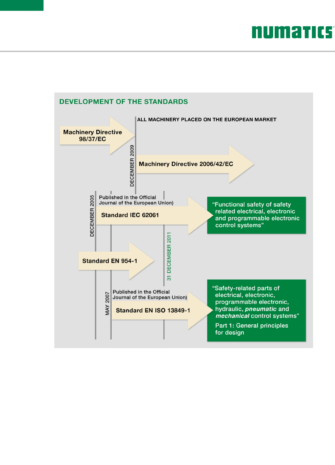
Three key concepts for the design of machinery and their safety functions have emerged from the
implementation of the new Machinery Directive 2006/42/EC:
• A risk analysis prior to design
• A particular consideration of the quantitative aspect of the safety functions in addition to the qualitative
approach
• The use of performance levels (PL)
Principle of the Safety of Machinery:
To guarantee the safety and health of persons exposed to the installation, operation, adjustment and maintenance
of machinery.
Risk Evaluation:
The manufacturer or supplier of a machine must see to it that a risk evaluation is conducted to determine the health
and safety requirements for persons involved in its operation. The machine must then be designed and constructed in
accordance with the results of the risk evaluation.
SAFETY OF
MACHINERY
Information subject to change without notice. For ordering information or regarding your local sales office visit www.asco.com. iii
SERIES
503
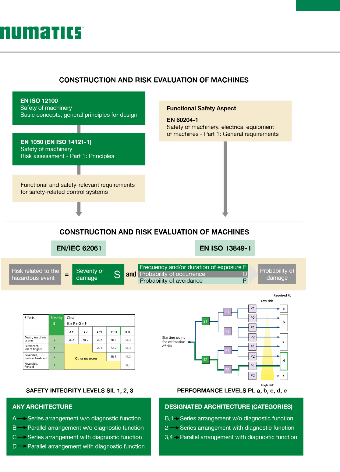
“Good engineering practice + probabilistic calculations”
RISK EVALUATION
Information subject to change without notice. For ordering information or regarding your local sales office visit www.asco.com.
iv
SERIES
503
RELIABILIT Y DATA
for components from manufacturers,
standards, databases etc.
MTTFd: Mean time to dangerous failure–
Value expressed in years
MTTFd
Rating for each channel
Low 3 years < MTTFd < 10 years
Medium 10 years < MTTFd < 30 years
High 30 years < MTTFd < 100 years
B10d
: Number of cycles after which 10% of a random sample of wearing components fail dangerously –
Value expressed in number of cycles.
DC
: Diagnostic Coverage
CCF
: Common Cause Failure. Measures to be taken to prevent a given cause (and its effect) from concurrently
disabling the multiple channels of a safety circuit.
Mission time T10
: In line with “good engineering practice” as recommended in EN ISO 13849-1, components
attaining this value must be replaced (precautionary principle).
DIAGNOSTIC COVERAGE
None Low Medium High
DC < 60% 60% < DC < 90% 90% < DC < 99% 99% < DC
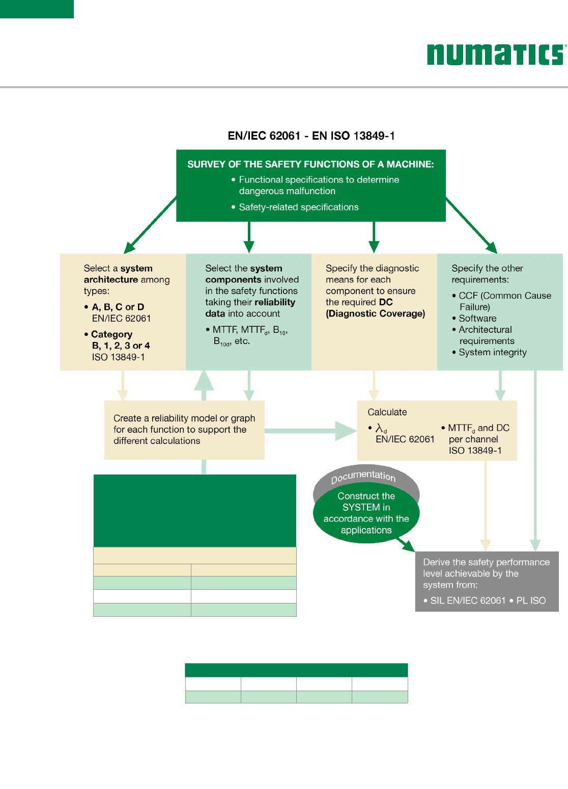
EN/IEC 62061 - EN ISO 13849-1
DESIGN PROCESS
Information subject to change without notice. For ordering information or regarding your local sales office visit www.asco.com. v
SERIES
503
Only the pneumatic part is described in the form of a subsystem in these examples. Other safety-related components
(e.g. protective devices, electrical logic elements) must be added to ensure the safety function is complete.
The examples shown here only relate to the stopping of hazardous movements. In pneumatics, safety measures
concerning the interruption of energy sources, the evacuation of potential energy (pressure contained in a part of
the circuit), and a “progressive” start-up after an unexpected shutdown should not be omitted.
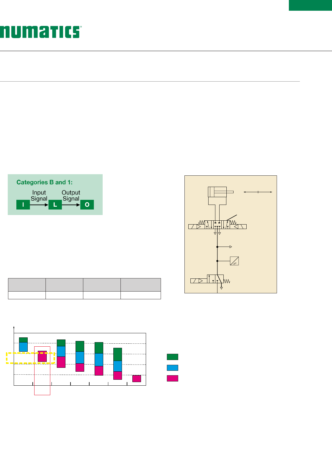
To attain a PL = c, category 1 architecture
• Safety function: Stopping of the potentially hazardous movement of cylinder 1A.
• Functional description:
Input ‘I’: not represented, movable guard or light barrier, etc.
Logic element ‘L’: not represented, PLC
• Calculation of the probability of dangerous failure:
Safety
function
Working
hours / day
Working
days / year Cycles / year
1 cycle = 5 s 16 h 240 days 2,764,800 cycles
B10d (1V1A – series 520) = 130,000,000 cycles, i.e. an operating time of 47 years, MTTFd=470 years “high”
By limiting the valve’s operating time to 47 years, this corresponds to a PL = c
PL
a
b
c
d
e
Category B
DCavg none Category 1
DCavg none
Category 2
DCavg low
Category 2
DCavg medium
Category 3
DCavg low
Category 3
DCavg medium
Category 4
DCavg high
PL Performance Levels
MTTFd rating for each channel = low
MTTFd rating for each channel = medium
MTTFd rating for each channel = high
Dangerous
movement
Solenoid valve
selected to ensure
safety compliance
Other consumers
and control systems
1A
1V 1A
0V 1A
0S1 P
FOR YOUR SAFETY
Information subject to change without notice. For ordering information or regarding your local sales office visit www.asco.com.
vi
SERIES
503
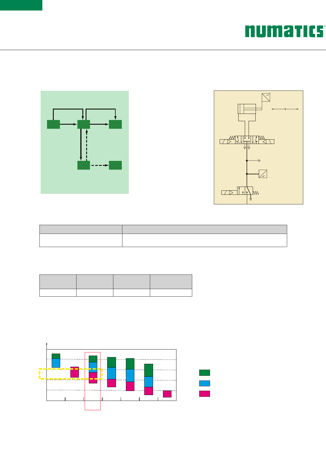
To attain a PL = c, category 2 architecture
• Safety function: Stopping of the potentially hazardous movement of cylinder 1A.
• Functional description:
Input ‘I’: not represented, movable guard or light barrier, etc.
Logic element ‘L’: not represented, PLC
Stop of cylinder ensured by: Diagnostics ensured by:
Output O: Valve 1V1B Cross-monitoring in L1 of the supply status coherence of coils 1V1Ba and 1V1Bb
and the limit switches 1S1
0V1: Energy isolating valve: ensures the system is exhausted in case of loop failure.
• Calculation of the probability of dangerous failure:
Safety
function
Working
hours / day
Working
days / year Cycles / year
1 cycle = 5 s 16 h 240 days 2,764,800 cycles
B10d (valve 1V1B - series 542)
= 44,912,670 cycles, i.e. an operating time of 16.2 ans,
MTTFd
= 162 years “high”
MTTFd (sensors 1S1)
= 45,000,000h, i.e. 11,718 years “high”
The case study shows: DC (Diagnostic Coverage) = 60% “low”
By limiting the valve’s operating time to 16.2 years
, this corresponds to a PL = c for the safety loop.
Category 2:
OTETE
I OL
Diagnostics
Diagnostics
Diagnostics
Diagnostics
Input
Signal
Output
Signal
Output
Signal
TE : Test equipment
OTE : Output of test equipment
PL
a
b
c
d
e
Category B
DCavg none Category 1
DCavg none
Category 2
DCavg low
Category 2
DCavg medium
Category 3
DCavg low
Category 3
DCavg medium
Category 4
DCavg high
PL Performance Levels
MTTFd rating for each channel = low
MTTFd rating for each channel = medium
MTTFd rating for each channel = high
1A
1S1 GDangerous
movement
Other consumers
and control systems
0V 1B
0S1 P
1V 1B
ab
FUNCTIONS
Information subject to change without notice. For ordering information or regarding your local sales office visit www.asco.com. vii
SERIES
503
FOR YOUR SAFETY
PL
a
b
c
d
e
Category B
DCavg none Category 1
DCavg none
Category 2
DCavg low
Category 2
DCavg medium
Category 3
DCavg low
Category 3
DCavg medium
Category 4
DCavg high
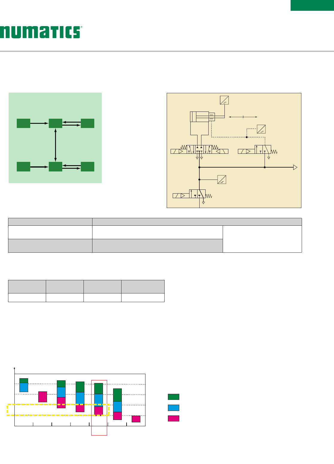
To attain a PL = d, category 3 architecture
• Safety function: Stopping of the potentially hazardous movement of cylinder 1A.
• Functional description:
Inputs ‘I1’ and ‘I2’: not represented, movable guard
or light barrier, etc.
Logic elements ‘L1’ and ‘L2’: not represented, PLC
Stop of cylinder ensured by:
Output O: Valve 1V1B Cross-monitoring in L1 of the supply status coherence of coils
1V1Ba and 1V1Bb and the limit switches 1S1 Cross-monitoring of L1/L2 status
coherence within the PLC
Output O2: Valve 2V1 controlling the
rod lock 2Z1 Pressure switch 2S1 for transmission of signal to L2
0V1B: Energy isolating valve: ensures the system is exhausted.
• Calculation of the probability of dangerous failure:
Safety
function
Working
hours / day
Working
days / year Cycles / year
1 cycle = 10 s 16 h 240 days 1,382,400 cycles
PL Performance Levels
MTTFd rating for each channel = low
MTTFd rating for each channel = medium
MTTFd rating for each channel = high
By limiting the operating time of the pressure switch and rod lock to 2.89 years
, this corresponds to
a PL = d for the safety loop.
B10d (valve 1V1B - series 542)
= 44,912,670 cycles, i.e. an operating time of 32.4 years, MTTFd = 324 years “high”
B10d (valve 2V1 - series 520)
= 20,000,000 cycles, i.e. an operating time of 14.5 years, MTTFd = 145 years “high”
B10d (pressure switch 2S1, dynamic rod lock 2Z1)
= 4,000,000 cycles, i.e. a mission time of T10 = 2.89 years,
MTTFd = 28.9 years “medium”
MTTFd (sensors 1S1)
= 45,000,000 h, i.e. 11,718 years “high”
The case study shows
: DC (Diagnostic Coverage) = 60% “low”, DC (2V1) = 99% “high”, DC* (2Z1) = 75%
i.e. for channel O2, DC = 78% “low”
1A
1S1
G
Dangerous
movement
Other consumers
and control systems
0V 1B
0S1 P
P
1V 1B
a b
2Z1
2V1
S21
Categories 3 and 4:
I1
I2
L1 O1
L2 O2
Diagnostics
Diagnostics
Input
Signal
Input
Signal
Output
Signal
Output
Signal
Cross-checking
diagnostics
* “ Good engineering practice” methods associate this type of component
with a low-to-medium DC to cover any of the component’s drift failures.
Information subject to change without notice. For ordering information or regarding your local sales office visit www.asco.com.
viii
SERIES
503 FUNCTIONS
1A
1S1 GDangerous
movement
Other consumers
and control systems
0V 1B
0S1 P
1V 1B
ab
PL
a
b
c
d
e
Category B
DCavg none Category 1
DCavg none
Category 2
DCavg low
Category 2
DCavg medium
Category 3
DCavg low
Category 3
DCavg medium
Category 4
DCavg high
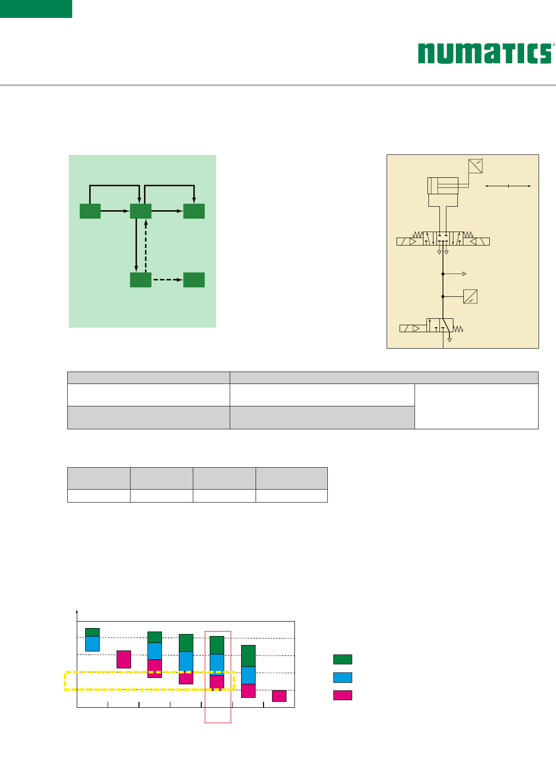
To attain a PL = d, category 3 architecture
• Safety function: Stopping of the potentially hazardous movement of cylinder 1A.
• Functional description:
Inputs ‘I1’ and ‘I2’: not represented, movable guard or light barrier, etc.
Logic elements ‘L1’ and ‘L2’: not represented, PLC
Stop of cylinder ensured by:
Output O: Valve 1V1B Comparison in L1 of the supply status of coils 1V1Ba
and 1V1Bb and the limit switches 1S1 Cross-monitoring of L1/L2 status
coherence within the PLC
Output O2: Valve 2V1 controlling the two 2/2
"cylinder stop" valves used as braking units Pressure switch 2S1 for transmission of signal to L2
0V1B: Energy isolating valve: ensures the system is exhausted.
• Calculation of the probability of dangerous failure:
Safety
function
Working
hours / day
Working
days / year Cycles / year
1 cycle = 10 s 16 h 240 days 1,382,400 cycles
By limiting the operating time of the pressure switch and rod lock to 2.89 years, this corresponds to
a PL = d for the safety loop.
Category 2:
OTETE
I OL
Diagnostics
Diagnostics
Diagnostics
Diagnostics
Input
Signal
Output
Signal
Output
Signal
TE : Test equipment
OTE : Output of test equipment
B10d (valve 1V1B - series 542) = 44,912,670 cycles, i.e. an operating time of 32.4 years, MTTFd = 324 years “high”
B10d (valve 2V1 - series 520) = 20,000,000 cycles, i.e. an operating time of 14.5 years, MTTFd = 145 years “high”
B10d (pressure switch 2S1, dynamic rod lock 2Z1) = 4,000,000 cycles, i.e. a mission time of T10 = 2.89 years,
MTTFd = 28.9 years “medium”
B10d (2/2 cylinder stop valves 2V3, 2V2) = 60,000,000 cycles, i.e. MTTFd = 434 years “high”
The case study shows: DC (1V1B)=60% “low”, DC (2V1)=99% “high”, DC* (2V3, 2V2)=60%, i.e. for channel O2,
DC = 78% “low”. * “ Good engineering practice” methods associate this type of component
with a low-to-medium DC to cover any of the component’s drift failures.
PL Performance Levels
MTTFd rating for each channel = low
MTTFd rating for each channel = medium
MTTFd rating for each channel = high

Table of Contents
503 Series
Technical and Operating Data 2
How to Order 3
Sandwich Pressure Regulators 4
Valve Regulator/Speed Control Plug-in Assembly 5
Regulator Service Kits and Parts 5
Sandwich Pressure Regulator Dimensions 6
Manifold Assembly 7
Valve on Manifold Block 7
Sandwich Port 4 Supply Block 11
Sandwich Pilot Supply Block 12
Sandwich Pressure Block 13
Sandwich Exhaust Block 13
Blank Station Plate Kit 14
Speed Control Kit 14
DIN Rail Clamp Kit 15
Blocking Discs 15
End Plate Kits 15
Manifold Assembly Dimensions 16
Internal/External Pilot Selection 17
Internal Muffler 17
G3 Electronics
Features and Benefits 19
Ethernet 21
PROFINET® 22
Ethernet POWERLINK® 23
Ether CAT® 24
EtherNet/IP™ DLR 25
CC-Link IE Field™ 26
I/O Modules 27
Miscellaneous Modules & Accessories 30
G3 Fieldbus Communication Assembly Dimensions 32
How to Order G3 Assembly Kit & G3 Electronics 33
How to Order Complete G3 Manifold Assemblies 34
Cables & Connectors 35
PROFINET® Cables & Connectors 38
Ethernet POWERLINK® Cables & Connectors 39
Ether CAT® Cables & Connectors 40
Ethernet Cables & Connectors 41
I/O Cables & Connectors 42

Information subject to change without notice. For ordering information or regarding your local sales office visit www.asco.com.
2
SERIES
503
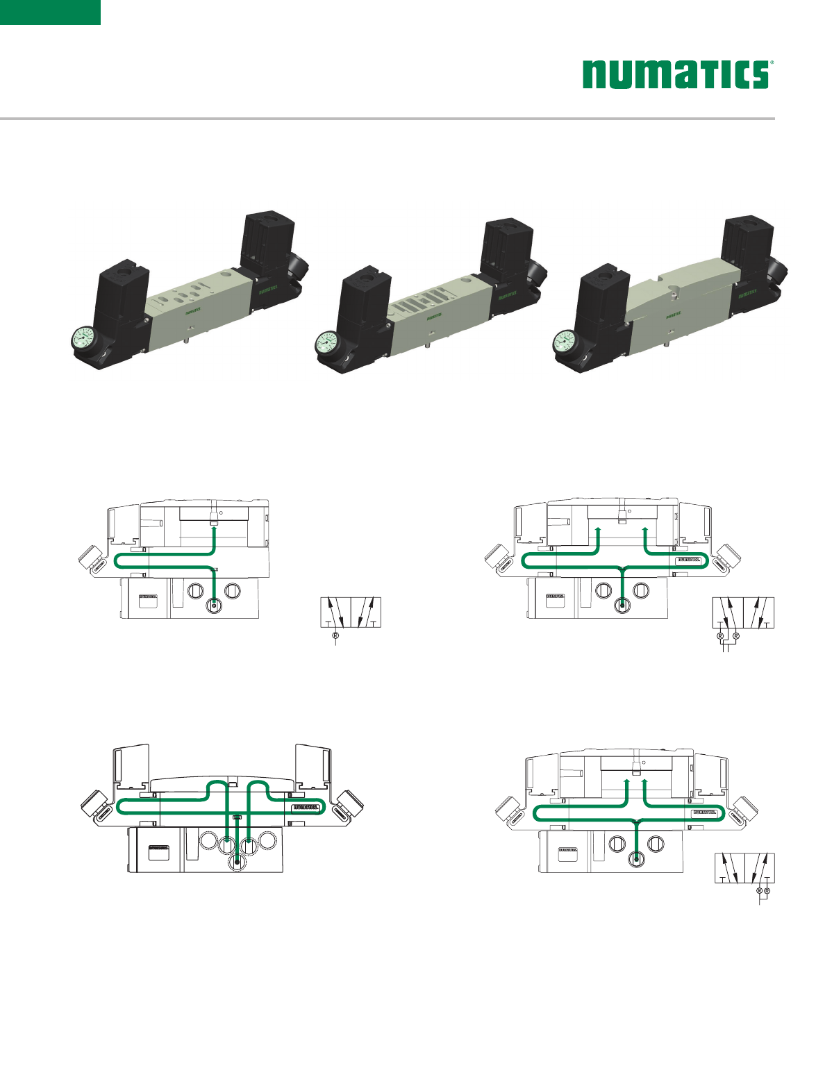
14
12
3 1 5
2 4
14
12
3 1 5
2 4
14
12
3 1 5
2 4
14
12
3 1 5
2 4
1214 2
4
315
single solenoid air pilot
2 position 4-way
double solenoid air pilot
2 position 4-way
double solenoid air pilot
3 position 4-way
open center
double solenoid air pilot
3 position 4-way
closed center
double solenoid air pilot
3 position 4-way
pressure center
12
14
24
31 5
12
14
24
31 5
double solenoid
2 position dual 3-way
“14” & “12” NO
double solenoid
2 position dual 3-way
“14” & “12” NC
(Spool & Sleeve)
Response Time (ms) Spool & Sleeve Rubber Seal
Energize Deenergize Energize Deenergize
5/2, Single Solenoid, Spring Return 20 60 20 60
5/2, Double Solenoid 15 N/A 20 N/A
5/3 Spring Centered – – 15 20
2x3/2 NC – – 15 25
2 X3/2 NO – – 15 20
Operating Data
All Solenoids Are Continuous Duty Rated 24 VDC
Power (Watts) 1.7
Holding Current (Amps) 0.071
ISO Proprietary
Valve Flow Data Cv NL/m
(6 - 5 Bar) Cv NL/m
(6 - 5 Bar)
5/2, Double Solenoid & Single Solenoid,
Spring Return (Spool & Sleeve) 1.1 110 0 1.2 1200
5/2, Double Solenoid & Single Solenoid,
Spring Return (Rubber Seal) 1.2 1200 1.4 1400
2X 3/2 NC-NC 0.9 900 1.0 1000
2X 3/2 NO-NO 0.9 900 1.0 1000
Double Solenoid, 3 pos. 4 way, Spring
Centered- Open to 4 and 2 in center 0.6 600 0.6 600
Double Solenoid, 3 pos. 4 way, Spring
Centered - Open Center 1.1 110 0 1.3 1300
Double Solenoid, 3 pos. 4 way, Spring
Centered - Closed Center 1.2 1200 1.4 1400
Performance Data
Valve Data Min. Max.
Pilot Pressure Range 29 PSI (2 Bar) 115 PSI (8 Bar)
Valve Operating Pressure Range 28" HG Vacuum 115 PSI (8 Bar)
Ambient Temperature Range -10 °C (-14 °F) 50 °C (122 °F)
5 Ported, 2 and 3 position, 4-way, Spool & Sleeve and Rubber
Seal, Cv: 1.2 - 1.4
• Solenoid air pilot actuated
• Low wattage – 1.7 watt for DC application
• DC solenoids polarity insensitive with surge suppression
Plug together circuit boards eliminate internal wiring
• Integral recessed gaskets
• IN Fittings to accommodate various tube sizes
• Simple conversion from internal to external pilot
• G3 Fieldbus electronics
• IP65 Certified
503 SERIES

Information subject to change without notice. For ordering information or regarding your local sales office visit www.asco.com. 3
SERIES
503
* For Regulator Type "E" must select "0" wiring option + "0" interface
Gauge Type
1 = PSI
2 = bar
Wiring Options
J = Plug-in, Receptacle Assembly
0 = Non Plug-in*
Options
A00 = Standard (No Options)
16N = Jumper for Supply Pressure
to Valve, 14 End
16P = Jumper for Supply Pressure
to Valve, 12 End
Interface
1 = Proprietary
2 = ISO 15407-2
0 = No Interface*
Reserved
Pressure Range
1 = 10 - 130 PSIG (0.7 - 9 bar)
3 = 3 - 30 PSIG (0.2 - 2 bar)
4 = 5 - 60 PSIG (0.3 - 4.1 bar)
Regulator Type
S = Single Reg. - Pressure to Port 1
D = Double Reg. - Pressure to Ports 5 & 3
E = Double Reg. - Pressure to Ports 4 & 2, w/o Valve*
T = Double Reg. - Pressure to Ports 1 & 3, 2
Pressure Selector
Product Type
R = Regulator
Revision
A = Initial Release
Product Series
503 = 26mm Valve
R 503 A R S 1 1 J A00 1 0
Regulator
* Spool and Sleeve not available with Functions 6, A, D, and N
Port Size
0 = No Port Size
Electrical
M = Plug-in, w/ Light, VDC
N = M12 Connector Pin#1 =
unused, #2 = Coil 12, #3 =
Common, #4 = Coil 14
Options
A00 = Standard (No Options)
11B = Flush Locking Manual
Override
11M = Without Manual Override
11Z = With push-button type
maintained manual operator
Voltage
F1 = 24 DC
Function
1 = 2 Position 4-Way (5/2), Spring Return
4 = 2 Position 4-Way (5/2), Dual Solenoid
5 = 3 Position 4-Way (5/3), Open Center, Dual Pressure
6 = 3 Position 4-Way (5/3), Blocked Center
7 = 3 Position 4-way (5/3), Open to A & B in Center
A = Dual 3-way, A normally open - B normally open
D = Dual 3-way, A normally closed - B normally closed
N = Differential Air Return w/o Spring
Actuation
B = Solenoid Pilot with Flush Non-Locking Override
Valve Type
1 = Spool and Sleeve*
2 = Rubber Packed
Revision
A = Initial Release
Product Series
503 = 26mm Valve
R 503 A 2 B 4 0 M A00 F1
How to Order
Valve
Information subject to change without notice. For ordering information or regarding your local sales office visit www.asco.com.
4
SERIES
503
1
2
3
4
5
1
SUPPLY
13
Two-pressure selector used for multi-pressure
applications.
1
SUPPLY
24 35
External outlet regulator used with jumper plate
for single or dual pressure.
Type RE Type RT
5
13
24
Dual pressure from a single supply.
1
SUPPLY
3
5
1
2
3
4
5
1
SUPPLY
1
Single pressure from a single supply.
Type RS Type RD
External Outlet RegulatorProprietary InterfaceISO 15407-2 Interface
Sandwich Pressure Regulators
Types: RS / RD / RE / RT
SANDWICH PRESSURE
REGULATORS
Information subject to change without notice. For ordering information or regarding your local sales office visit www.asco.com. 5
SERIES
503
Part Number Description
M503AR428759001 3-30 PSIG Regulator Kit
M503AR428759002 5-60 PSIG Regulator Kit
M503AR428759003 10-130 PSIG Regulator Kit
M503AR428759004 0.2-2.0 Bar Regulator Kit
M503AR428759005 0.3-4.0 Bar Regulator Kit
M503AR428759006 0.7-9.0 Bar Regulator Kit
Regulator Unit Kits
(includes regulator assembly, gaskets, screws)
Regulator Kits and Service Parts
Regulator Service Kit
MOUNTING 8503AMM22MA0010
SPEED CONTROL R503AS425575002
REGULATOR R503ARS11JA0010
VALVE R503A2B10MA00F1
Valve Regulator / Speed Control Plug-in Assembly
VALVE REGULATOR/
SPEED CONTROL
PLUG-IN ASSEMBLY
Information subject to change without notice. For ordering information or regarding your local sales office visit www.asco.com.
6
SERIES
503
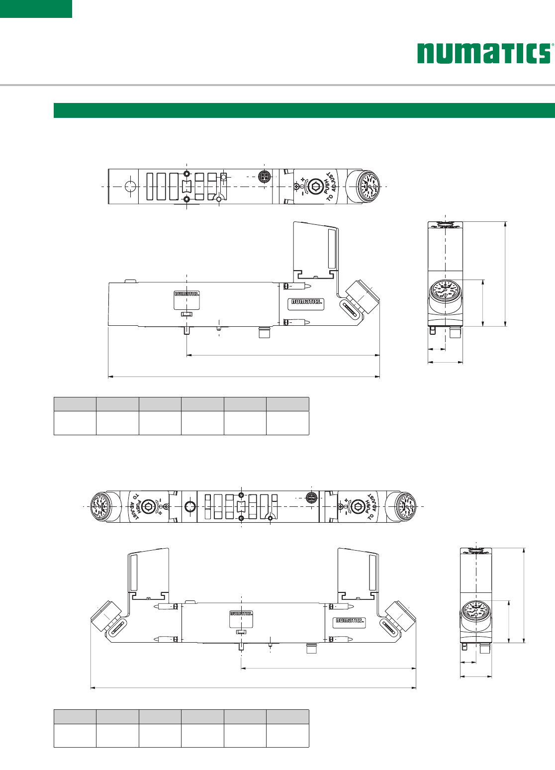
A
B
C
D
F
E
A
B
C
D
F
E
A B C D E F
268.2
(10.56)
144.1
(5.673)
78.2
(3.08)
34.8
(1.37)
26
(1.02)
13
(0.51)
Double Regulator
A B C D E F
202.7
( 7. 9 8)
144.1
(5.673)
78.2
(3.08)
34.8
(1.37)
26
(1.02)
13
(0.51)
Single Regulator
Dimensional Drawing - Sandwich Pressure Regulator
Dimensions: mm (inches)
Information subject to change without notice. For ordering information or regarding your local sales office visit www.asco.com. 7
SERIES
503
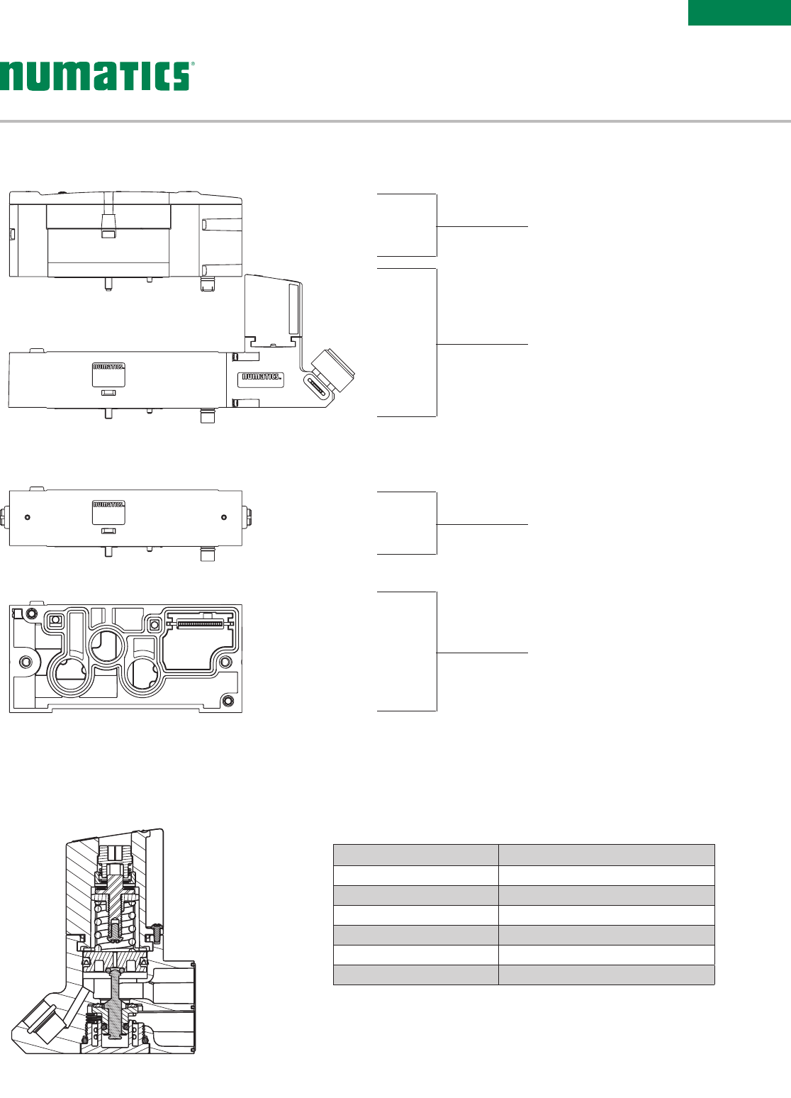
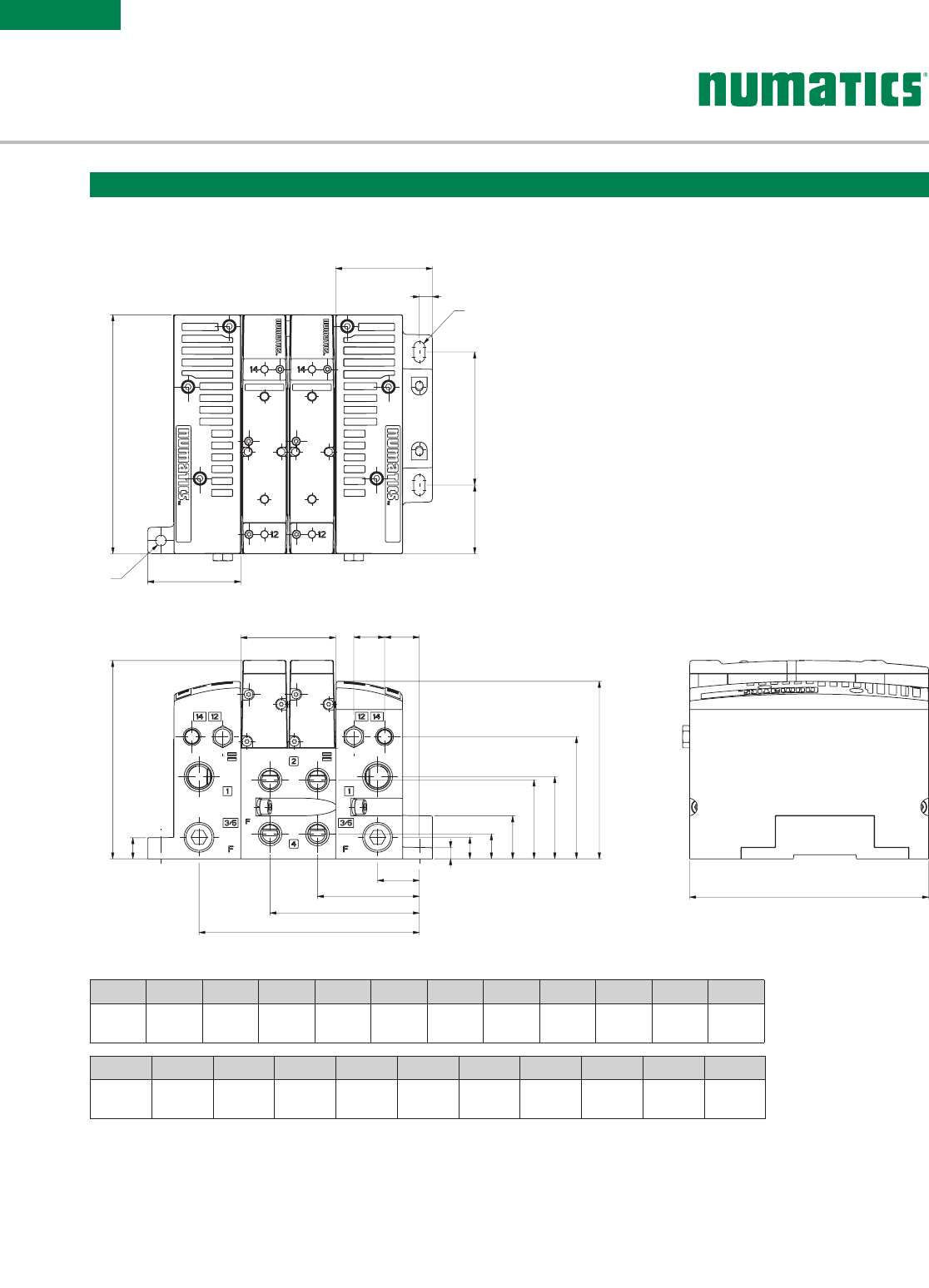
Dimensional Drawing - Plug-in Valve Mounted
Dimensions: mm (inches)
G
F
E
D
H
A
B
C
A B C D E F G H
112.9
(4.445)
44.9
(1.768)
14.2
(0.56)
54
(2.13)
43.7
(1.72)
16.7
(0.66)
53.3
(2.098)
136
(5.35)
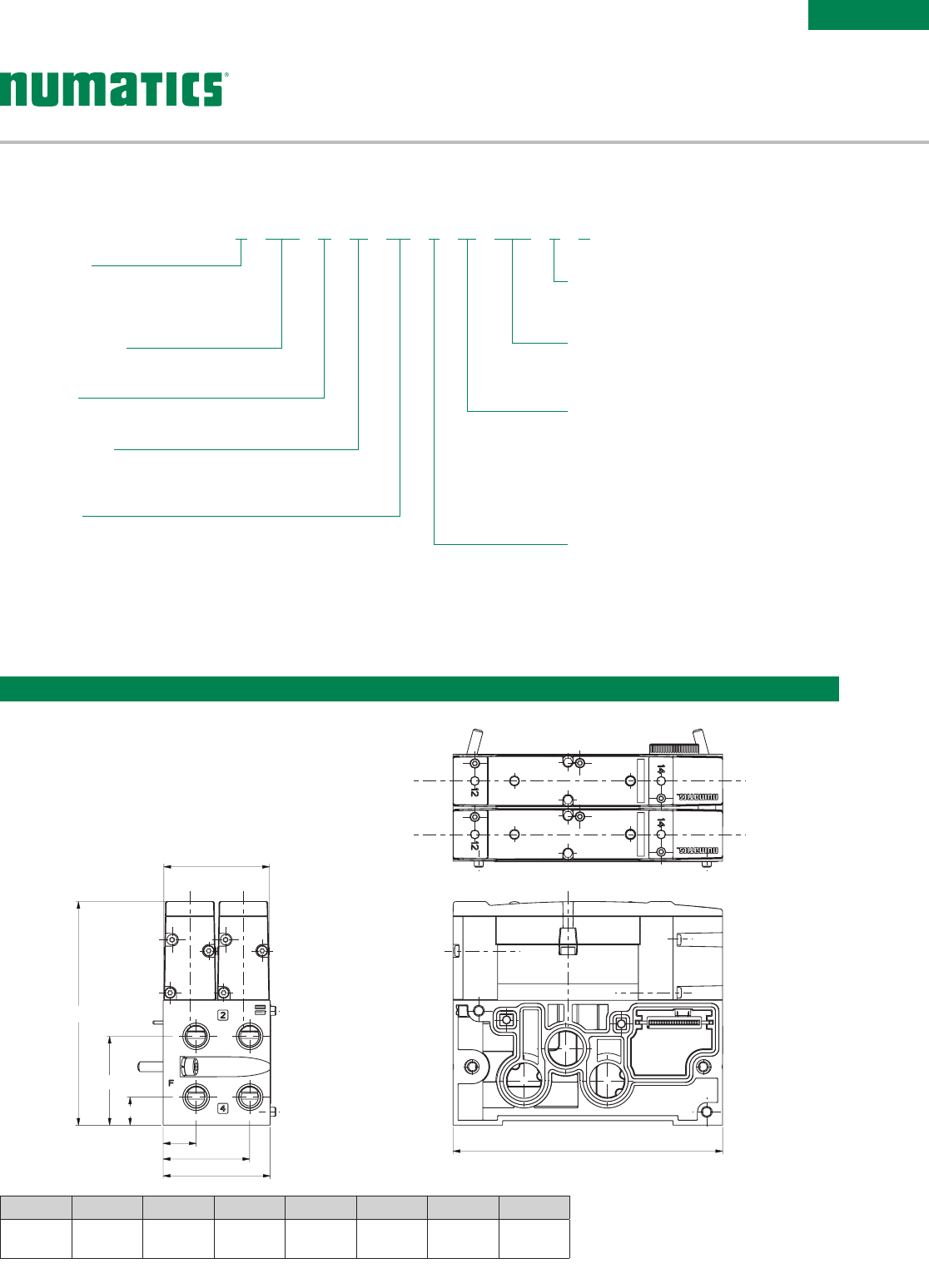
1 Port Type '8' and 'G' only available with Port Size '2'
2 Only available with 'M' Wiring and 'M2' Mounting
3 Only available with 'X' Wiring
4 Only available with Product Type 'M' and 'S2' Mounting
5 Only available with Product Type 'M' and 'M2' Mounting
Port Size
2 = 1/4
3 = 3/8
H = 8mm
K = 10mm
Wiring Options
M = Plug-in, Receptacle Assembly
0 = Non-Plug-in
U = M12 Connectors w/Pass Thru
Communication Pin 1 = Coil 14,
Pin 2 = Not Used, Pin 3 = Common,
Pin 4 = Not Used4
X = 0 & 24 VDC Separation at First Station
of a Safety Zone5
Options
A00 = Standard (No Options)
83H = Pilot Separation for Station 13
Interface
1 = Proprietary
2 = ISO15407-2
Mounting
S2 = Manifold Subbase, 2 Stations, Side Ports,
Single Z-Board
M2 = Manifold Subbase, 2 Stations, Side Ports,
Double Z-Board
Product Type
M = Manifold Subbase
Z = Mid-Station Supply2
Revision
A = Initial Release
Product Series
503 = 26mm Valve
Port Type
8 = NPTF1
G = ISO228/1-G1
K = Push-in Fittings
8 503 A M S2 2 M A00 1 0
How to Order
Manifolds
MANIFOLD
ASS EMBLY
Information subject to change without notice. For ordering information or regarding your local sales office visit www.asco.com.
8
SERIES
503
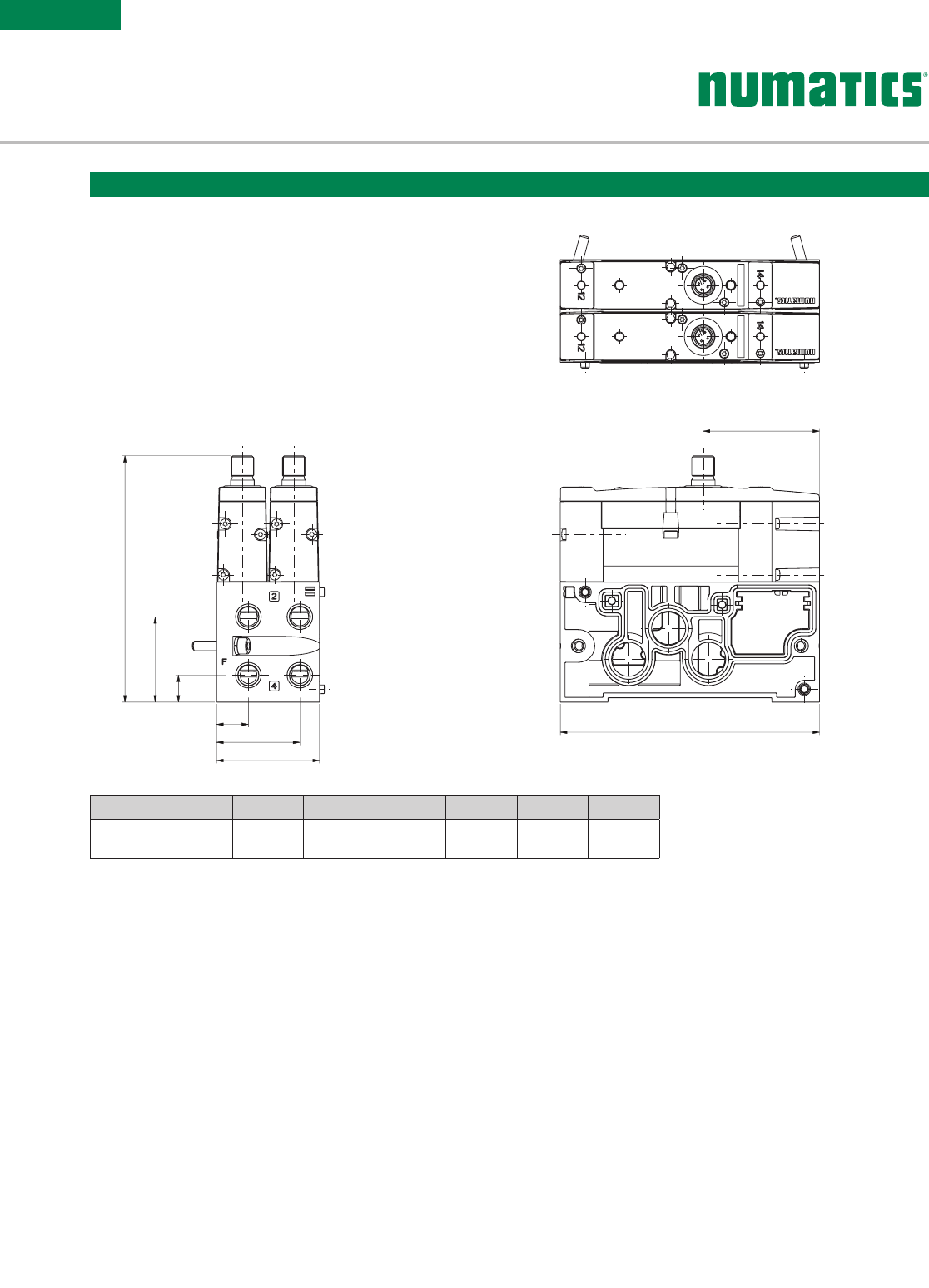
A B C D E F H J
129.4
(5.094)
44.9
(1.768)
14.2
(0.56)
54
(2.13)
43.7
(1.72)
16.7
(0.66)
136
(5.35)
61
(2.4)
A
B
C
F
E
D
H
J
Dimensional Drawing - M12 Valve Mounted
Dimensions: mm (inches)
Information subject to change without notice. For ordering information or regarding your local sales office visit www.asco.com. 9
SERIES
503
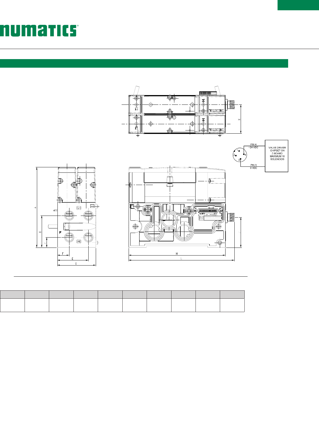
Dimensional Drawing - Plug-in Valve Mounted (X Wiring Option)
Dimensions: mm (inches)
A B C D E F G H J K
112.9
(4.445)
44.85
(1.766)
14.15
(0.557)
54
(2.126)
43.65
(1.719)
16.65
(0.656)
148.654
(5.853)
136
(5.354)
42.5
(1.673)
40.5
(1.594)
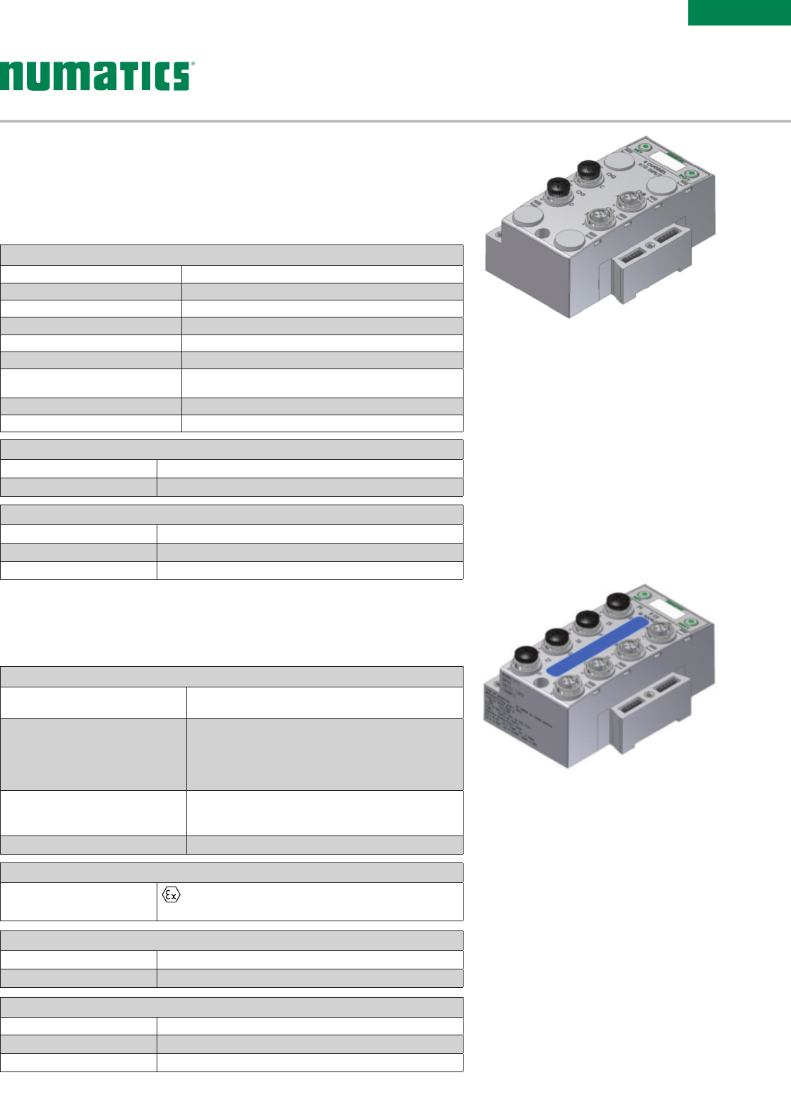
Zoned Power Manifold Base (“X” Wiring”)
• Via M12 Connector supplies power to up to 16 valve solenoid coils
• All valve solenoid coils are controlled via the attached G3 node
• When M12 connector is externally supplied by a Safety Relay or Safety Output via a Safety PLC the
valves within the Safety zone become one of the redundant channels of a Category 3 or 4 circuit
Information subject to change without notice. For ordering information or regarding your local sales office visit www.asco.com.
10
SERIES
503
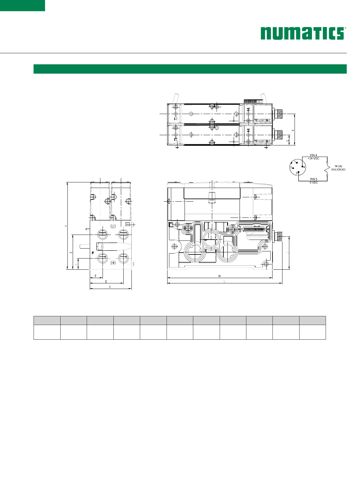
Dimensional Drawing - Plug-in Valve Mounted (U Wiring Option)
Dimensions: mm (inches)
A B C D E F G H J K L
112.9
(4.445)
44.85
(1.766)
14.15
(0.557)
54
(2.126)
43.65
(1.719)
16.65
(0.656)
148.654
(5.853)
136
(5.354)
42.5
(1.673)
40.5
(1.594)
13.5
(0.531)
Pilot Valve Manifold Base (“U” Wiring)
• Allows mounted pilot valves to be electrically controlled via M12 connector; isolated from the connected
G3 node
• When M12 connector is externally supplied by a Safety Relay or Safety Output via a Safety PLC the pilot
valves become one of the redundant channels of a Category 3 or 4 circuit
• Pilot supply valves when used to supply Pilot Operated Check Valves, Rod-Locks, Pilot Operated Spring
Return Valves etc provide one of the channels required for Category 3 & 4 circuits
Information subject to change without notice. For ordering information or regarding your local sales office visit www.asco.com. 11
SERIES
503
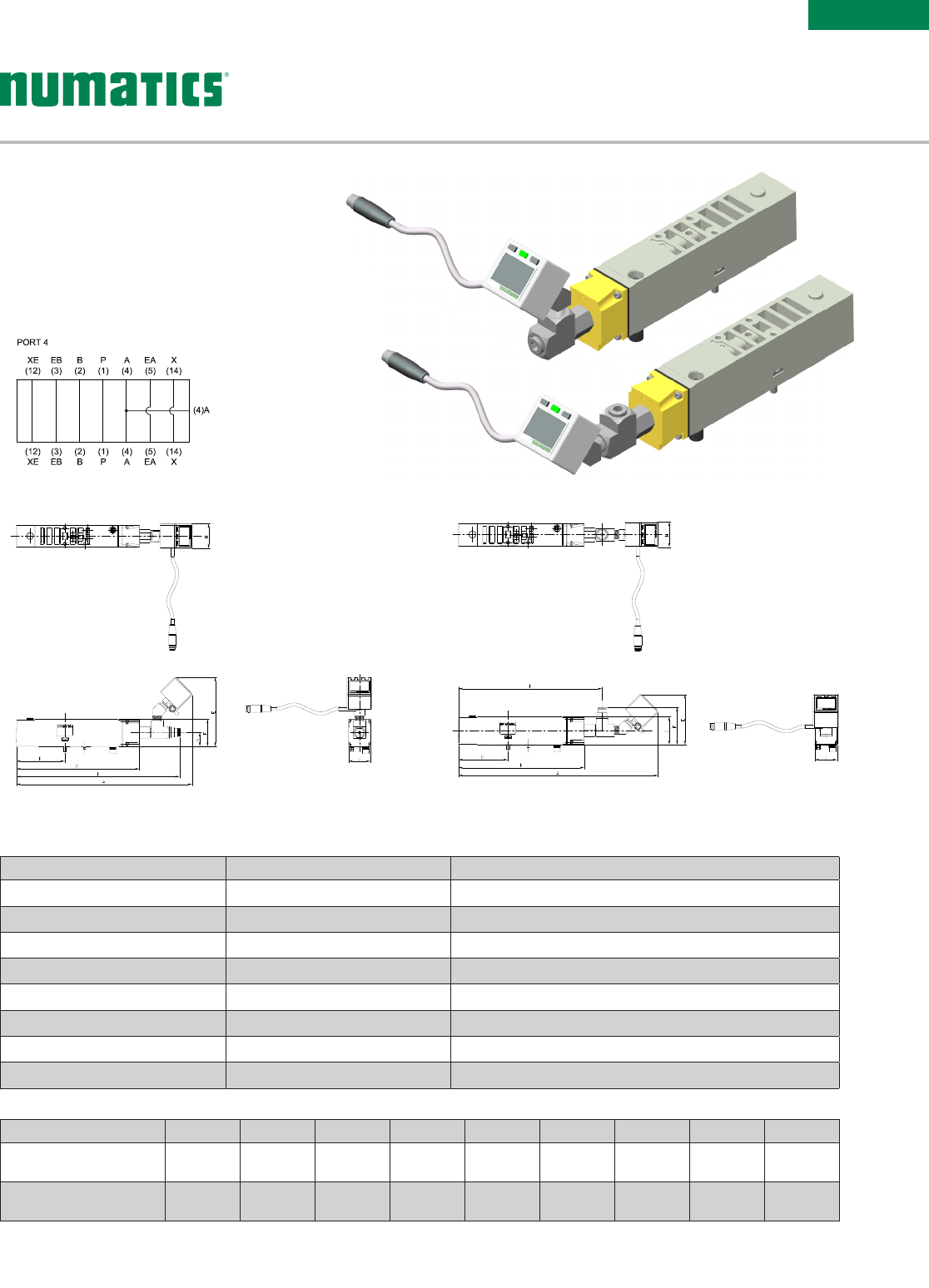
HorizontalVertical
A B C D E F G H J
w/Vertical DPS280 212.48
(8.365)
19 7. 21
( 7.76 4)
148.78
(5.857)
58.58
(2.306)
83.55
(3.289)
33
(1.299)
17
(0.669)
30
(1.181)
26.5
(1.043)
w/Horizontal DPS280 236.02
(9.292)
148.78
(5.857)
58.58
(2.306)
169.98
(6.692)
5951
(2.343)
44.23
(1.741)
33
(1.299)
30
(1.18 4)
26.5
(1.043)
Part Number Port for Pilot Supply Description
8503AU516663005 Plugged Proprietary Port 4 supply block with Vertical DPS280
8503AU516663009 Plugged Proprietary Port 4 supply block with Horizontal DPS280
K503AU516663006 5/32 (4mm) Push-In Fitting Proprietary Port 4 supply block with Vertical DPS280
K503AU516663010 5/32 (4mm) Push-In Fitting Proprietary Port 4 supply block with Horizontal DPS280
8503AU516663003 Plugged ISO15407-2 Port 4 supply block with Vertical DPS280
8503AU516663007 Plugged ISO15407-2 Port 4 supply block with Horizontal DPS280
K503AU516663004 5/32 (4mm) Push-In Fitting ISO15407-2 Port 4 supply block with Vertical DPS280
K503AU516663008 5/32 (4mm) Push-In Fitting ISO15407-2 Port 4 supply block with Horizontal DPS280
• Monitors pressure to external devices by
DPS280 Pressure Switch
• Can be use to supply pressure from Port 4 of
valve to pilot Safety zone of manifold via Pilot
Separation Pilot block
• Vertical and Horizontal orientation of DPS 280
allows for mounting on adjacent stations
SANDWICH PORT 4
SUPPLY BLOCK
Information subject to change without notice. For ordering information or regarding your local sales office visit www.asco.com.
12
SERIES
503
A B C D E F
161
(6.350)
148.78
(5.857)
58.58
(2.306)
33
(1.299)
17
(0.669)
26.5
(1.043)
Part Number Port for Pilot Supply Description
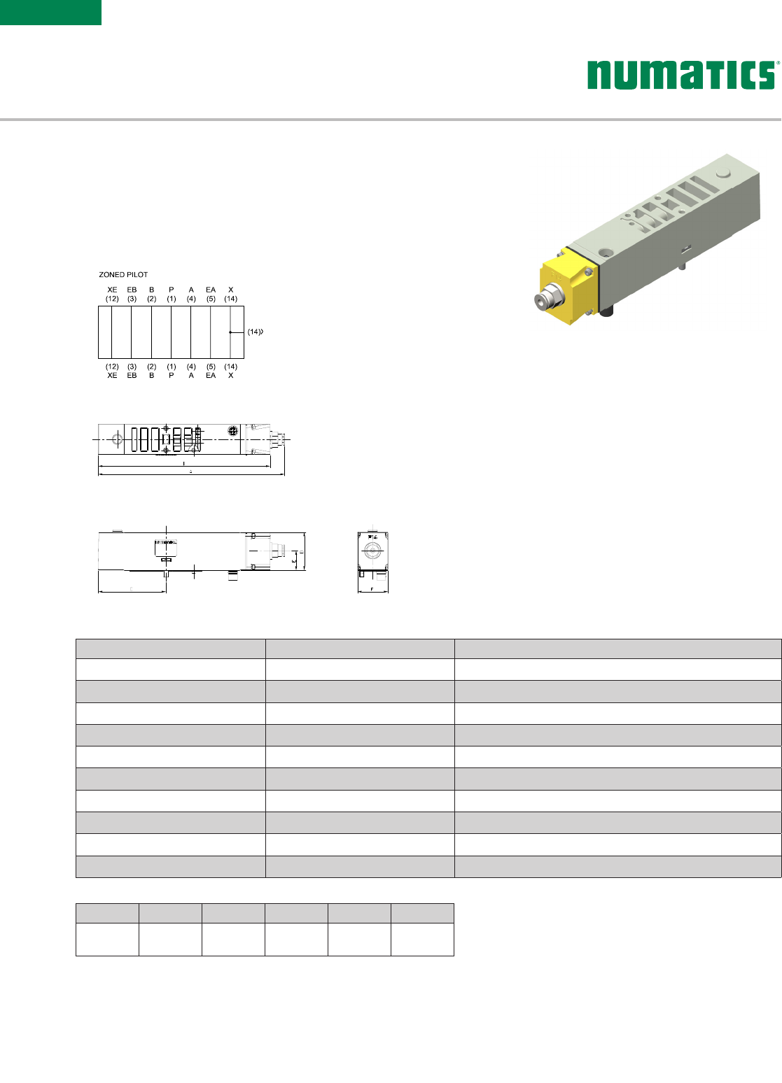
8503AP428300008 1/4 NPTF Proprietary Zoned Pilot Supply Block
G503AP428300008 G 1/4 Proprietary Zoned Pilot Supply Block
K503AP428300010 5/32 (4mm) Push-In Fitting Proprietary Zoned Pilot Supply Block
8503AP428300007 1/4 NPTF ISO15407-2 Zoned Pilot Supply Block
G503AP428300007 G 1/4 ISO15407-2 Zoned Pilot Supply Block
K503AP428300009 5/32 (4mm) Push-In Fitting ISO15407-2 Zoned Pilot Supply Block
8503AP428300006 1/4 NPTF Proprietary Independent Pilot Supply Block
G503AP428300006 G 1/4 Proprietary Independent Pilot Supply Block
8503AP428300005 1/4 NPTF ISO15407-2 Independent Pilot Supply Block
G503AP428300005 G 1/4 ISO15407-2 Independent Pilot Supply Block
• Allows for introduction of secondary pilot supply to either an
individual valve or zone of valves on manifold. Supply to zone of
manifold requires selection of Manifold Block and End Plates with
Pilot Separation option
• Pilot Supply air can be from either an external valve or integrated
into the manifold via the Port 4 Supply Block
SANDWICH PILOT
SUPPLY BLOCK
Information subject to change without notice. For ordering information or regarding your local sales office visit www.asco.com. 13
SERIES
503
A
1
C
B
D
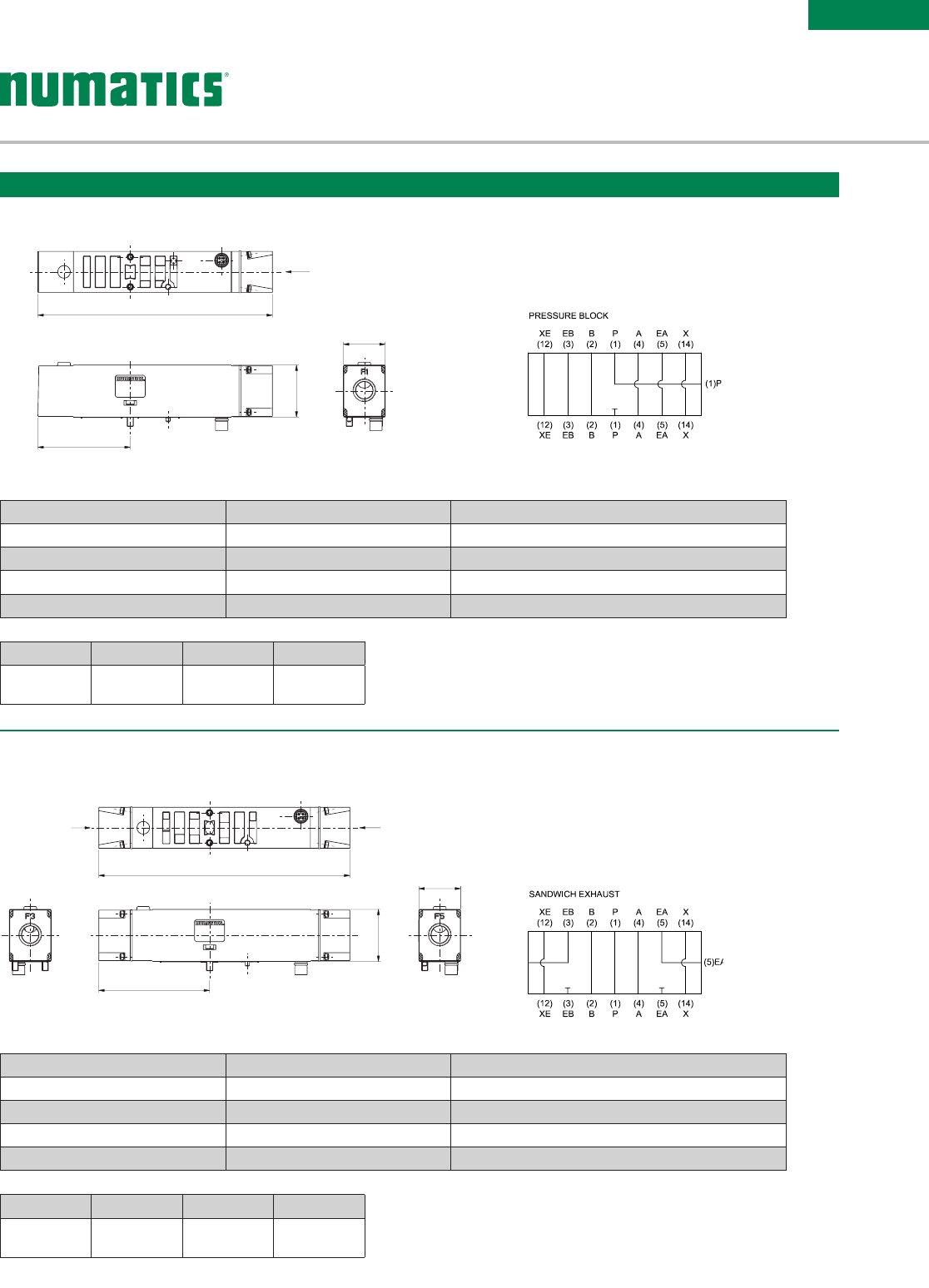
• Used to supply a separate pressure to a single
valve station without needing blocking disks
A B C D
159.2
(6.268)
70.2
(2.764)
33
(1.3)
26.5
(1.04)
Part Number Port Type Description
8503AX428300002 1/4 NPTF Proprietary Sandwich Exhaust Block
G503AX428300002 G 1/4 Proprietary Sandwich Exhaust Block
8503AX428300001 1/4 NPTF ISO 15407-2 Sandwich Exhaust Block
G503AX428300001 G 1/4 ISO 15407-2 Sandwich Exhaust Block
Sandwich Exhaust Block Kit
• Used to isolate the exhaust of a single valve
station from the manifold
• Allows faster exhaust response by re-routing
exhaust externally to the manifold
Sandwich Exhaust Block
A
B
C
D
53
Dimensional Drawing - Sandwich Pressure Block
Dimensions: mm (inches)
A B C D
148.8
(5.858)
58.6
(2.307)
33
(1.3)
26.5
(1.04)
Part Number Port Type Description
8503AW428300004 1/4 NPTF Proprietary Sandwich Pressure Block
G503AW428300004 G 1/4 Proprietary Sandwich Pressure Block
8503AW428300003 1/4 NPTF ISO 15407-2 Sandwich Pressure Block
G503AW428300003 G 1/4 ISO 15407-2 Sandwich Pressure Block
Sandwich Pressure Block Kit
Information subject to change without notice. For ordering information or regarding your local sales office visit www.asco.com.
14
SERIES
503
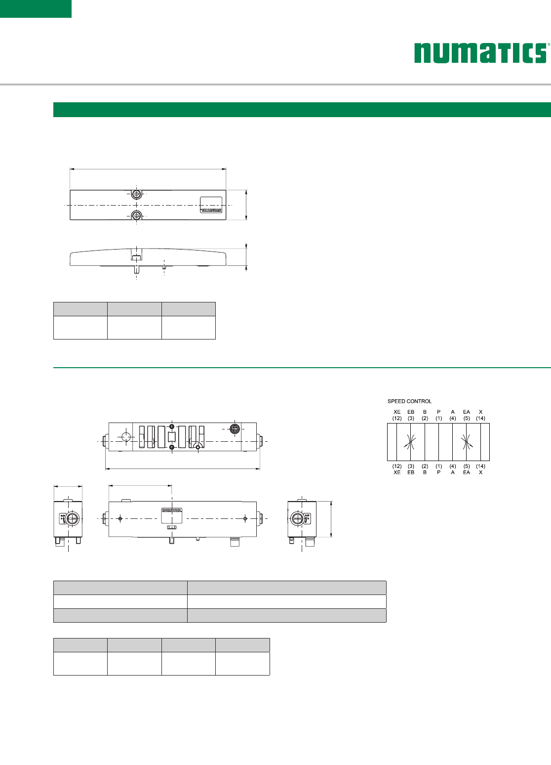
A B C D
142
(5.591)
58
(2.283)
33
(1.3)
26
(1.02)
Part Number Description
R503AS425575002 Proprietary Sandwich Speed Control
R503AS425575001 ISO 15407-2 Sandwich Speed Control
A
DB
C
• Used to block off a manifold station block for
future use
A
B
C
Speed Control Kit
Dimensional Drawing - Blank Station Plate Kit
P503AB428359001
Dimensions: mm (inches)
A B C
136
(5.354)
26
(1.024)
14.8
(0.58)
Information subject to change without notice. For ordering information or regarding your local sales office visit www.asco.com. 15
SERIES
503
PORT TYPE NPTF GPUSH-IN PUSH-IN PUSH-IN PUSH-IN
Port Type
13/5 12/14 13/5 12/14 13/5 12/14 13/5 12/14 13/5 12 /14 13/5 12/14
Port Size
3/8 3/8 1/8 3/8 3/8 1/8 3/8 3/8 1/8 1/2 1/2 1/8 10mm 10mm 6mm 12mm 12mm 6mm
Vertical w/o mufer,
w/o DIN 8503AK428327001 G503AK428327013 K503AK428327003 K503AK428327005 K503AK428327015 K503AK428327017
Vertical w/o mufer,
w/DIN 8503AK428327002 G503AK428327014 K503AK428327004 K503AK428327006 K503AK428327016 K503AK428327018
Vertical w/mufer,
w/o DIN 8503AK428327007 G503AK428327019 K503AK428327009 K503AK428327011 K503AK428327021 K503AK428327023
Verical w/mufer,
w/DIN 8503AK428327008 G503AK428327020 K503AK428327010 K503AK428327012 K503AK428327022 K503AK428327024
Vertical w/o mufer,
w/o DIN, w/Pilot
Separation
8503AK428327025 G503AK428327037 K503AK428327027 K503AK428327029 K503AK428327039 K503AK428327041
Vertical w/o mufer,
w/DIN, w/Pilot
Separation
8503AK428327026 G503AK428327038 K503AK428327028 K503AK428327030 K503AK428327040 K503AK428327042
Vertical w/mufer,
w/o DIN, w/Pilot
Separation
8503AK428327031 G503AK428327043 K503AK428327033 K503AK428327035 K503AK428327045 K503AK428327047
Verical w/mufer,
w/DIN, w/Pilot
Separation
8503AK428327032 G503AK428327044 K503AK428327034 K503AK428327036 K503AK428327046 K503AK428327048
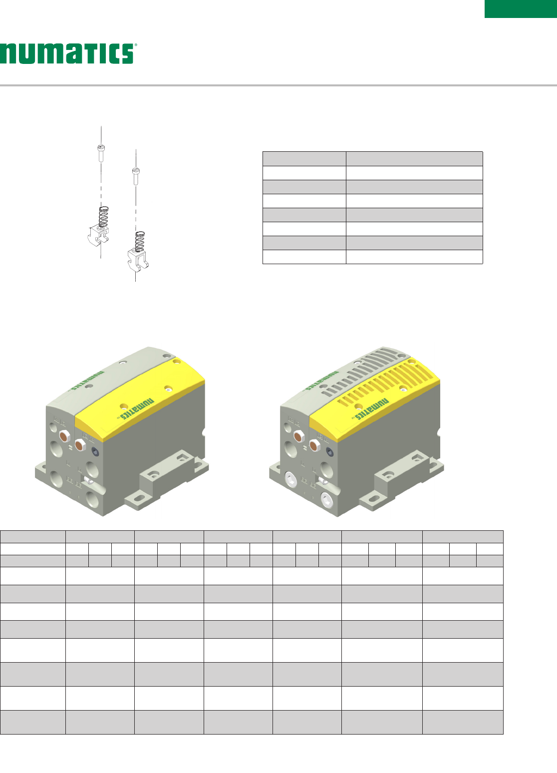
Zoned Safety End Plate Kit - Threaded
Ports Part
1P 50 3 A D 43119 10 0 1
3P503AD431191002
5P503AD431191003
1 + 3 P503AD431191004
1 + 5 P503AD431191005
3 + 5 P5 0 3A D 4 311910 0 6
1, 3, 5 P 50 3 A D 43119 10 0 7
Blocking Disc Kits
(Includes tag to label ports blocked)
DIN Rail Clamp Kit
239-980
Information subject to change without notice. For ordering information or regarding your local sales office visit www.asco.com.
16
SERIES
503
A
B
J
G
H
Y
X
W
V
UTSR
QP
N
M
A Ref.
KL
Ø6.4
F
E
D
6.3 Wide Slot
(2) Places
C
A B C D E F G H J K L M
136
(5.354)
53
(2.087)
55.1
(2.17 )
7. 5
(0.3)
75.8
(2.98)
39.1
(1.54)
112.9
(4.445)
12
(0.47)
54
(2.13)
17. 5
(0.69)
19.8
(0.78)
101.1
(3.98)
N P Q R S T U V W X Y
69.5
(2.74)
46.8
(1.843)
44.9
(1.77)
24.4
(0.96)
14.2
(0.56)
12.3
(0.48)
6.4
(0.25)
23.8
(0.94)
58
(2.28)
85
(3.346)
125.4
(4.937)
Dimensional Drawing - Manifold Assembly
Dimensions: mm (inches)
Information subject to change without notice. For ordering information or regarding your local sales office visit www.asco.com. 17
SERIES
503
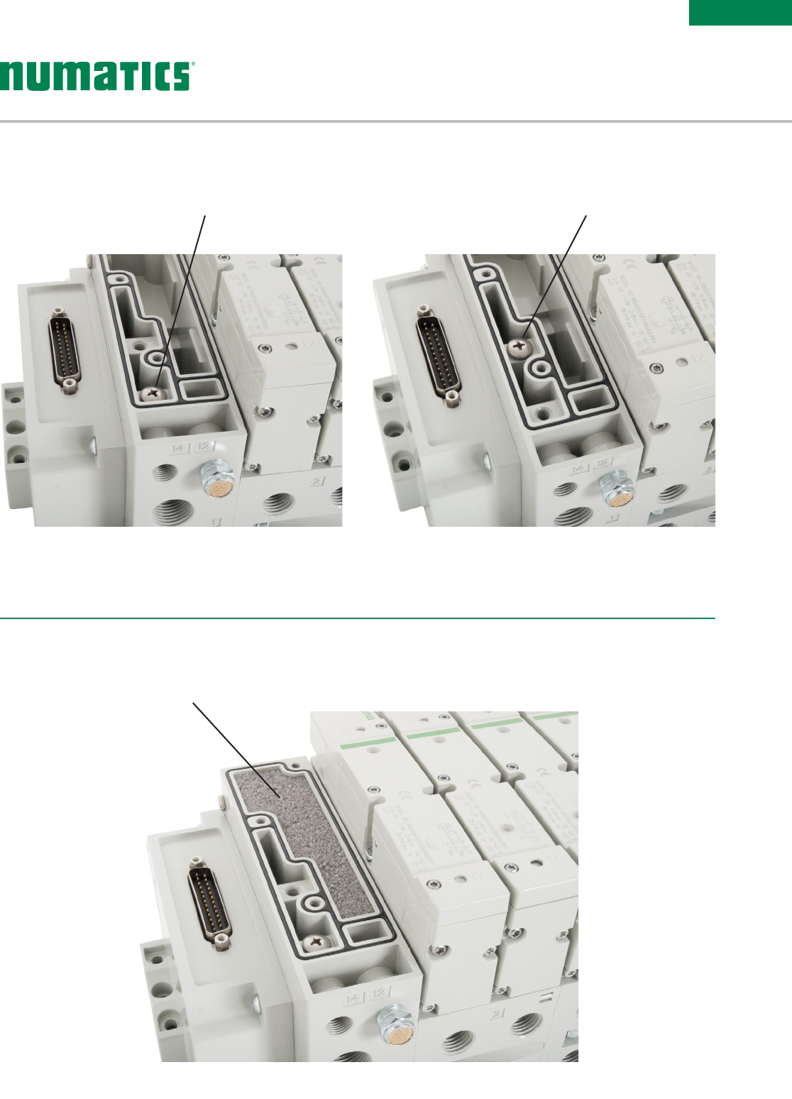
Muffler
Internal Pilot
Supply Plug Location
Internal Muffler
Internal Pilot External Pilot
For External Pilot
Supply Plug Location
• Pilot selection can only be made at the left hand end plate when the manifold has pilot separation

Table of Contents
Section 1
Features and Benefits 19
Ethernet 21
PROFINET® 22
Ethernet POWERLINK® 23
Ether CAT® 24
EtherNet/IP™ DLR 25
CC-Link IE Field™ 26
I/O Modules 27
Miscellaneous Modules & Accessories 30
G3 Fieldbus Communication Assembly Dimensions 32
Section 2 - How to Configure & Order G3 Electronics
How to Order G3 Assembly Kit & G3 Electronics 33
How to Order Complete G3 Manifold Assemblies 34
Cables & Connectors 35
PROFINET® Cables & Connectors 38
Ethernet POWERLINK® Cables & Connectors 39
Ether CAT® Cables & Connectors 40
Ethernet Cables & Connectors 41
I/O Cables & Connectors 42
G3 | Communication Node and I/O
Fieldbus Electronics
Information subject to change without notice. For ordering information or regarding your local sales office visit www.asco.com. 19
ELECTRONICS
G3 Fieldbus
PROFINET is a registered trademark of Profibus Nutzerorganisation e.V.
Ethernet POWERLINK is a registered trademark of Bernecker + Rainer Industrie – Elektronik Ges.m.b.H.
CC-Link is a registered trademark and CC-Link IE Field is a trademark of the CC-Link Partner Association.
*
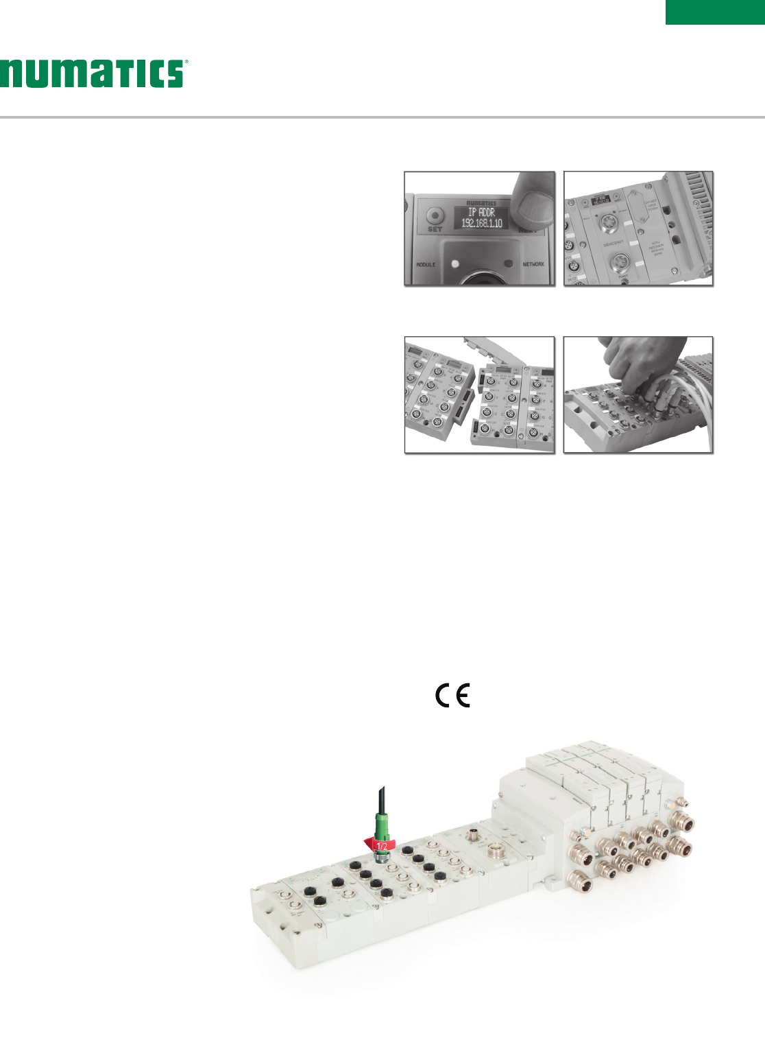
Easy, Robust ConnectionsHighly Distributable
Auto Recovery ModuleGraphic Display for
Conguration & Diagnostics
• 1/2 turn for faster I/O connections
• Backwards compatible with standard
M12 cables/connectors
• Meets the same IP/NEMA standards
as M12/Micro cables/connectors
• Same cost as standard M12/Micro
cables/connectors
• See pages 42 & 43 for cables with
SPEEDCON® connector technology.
*Numatics I/O with
SPEEDCON® technology
Supported Protocols
• Ethernet
• PROFINET®
• Ethernet POWERLINK®
• EtherCAT®
• EtherNet/IP™ DLR
w/QuickConnect™
• CC-Link IE Field™
G3 Fieldbus Communications Electronics
Why use Numatics Fieldbus communication electronics?
Modular Reality...
No internal wiring simplifies assembly
• SPEEDCON M12 connector technology allows for fast and
efficient ½ turn I/O connector attachment
• Power connector allows output power to be removed while
inputs and communication are left active
• IP65 protection
• Up to 1200 Input/1200 Output capability with one
communication node! (Present physical I/O combinations allows
1200 I/544 O)
• 32 valve solenoids per manifold up to 17 manifolds per
communication node!
• One node supports 16 I/O modules – Analog I/O, Digital I/O
(NPN & PNP) and Specialty
• Innovative clip design allows easy module removal/replacement
without dismantling manifold
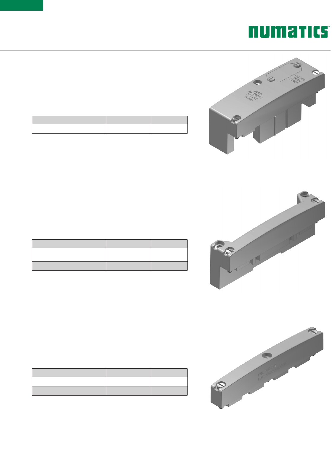
• Auto Recovery Module (ARM) protects configuration information
during a critical failure. Allows configuration information to be
saved and reloaded to replacement module automatically
Commissioning Capabilities
• Set network address (including
IP & Subnet mask for Ethernet)
• Set baud rate
• Set auto or manual I/O sizes
• Set fault/idle output states
• Set brightness
• Set factory defaults
• Visual diagnostics
• Shorted and open load
detection
• Shorted sensor/cable detection
• Low & missing power detection
• Missing module detection
• Self-test activation
• Log of network errors
• Distribution errors
G3 Fieldbus - Electronics Made Easy!
Innovative Graphic Display is used for easy commissioning, visual
status & diagnostics.
Information subject to change without notice. For ordering information or regarding your local sales office visit www.asco.com.
20
ELECTRONICS
G3 Fieldbus
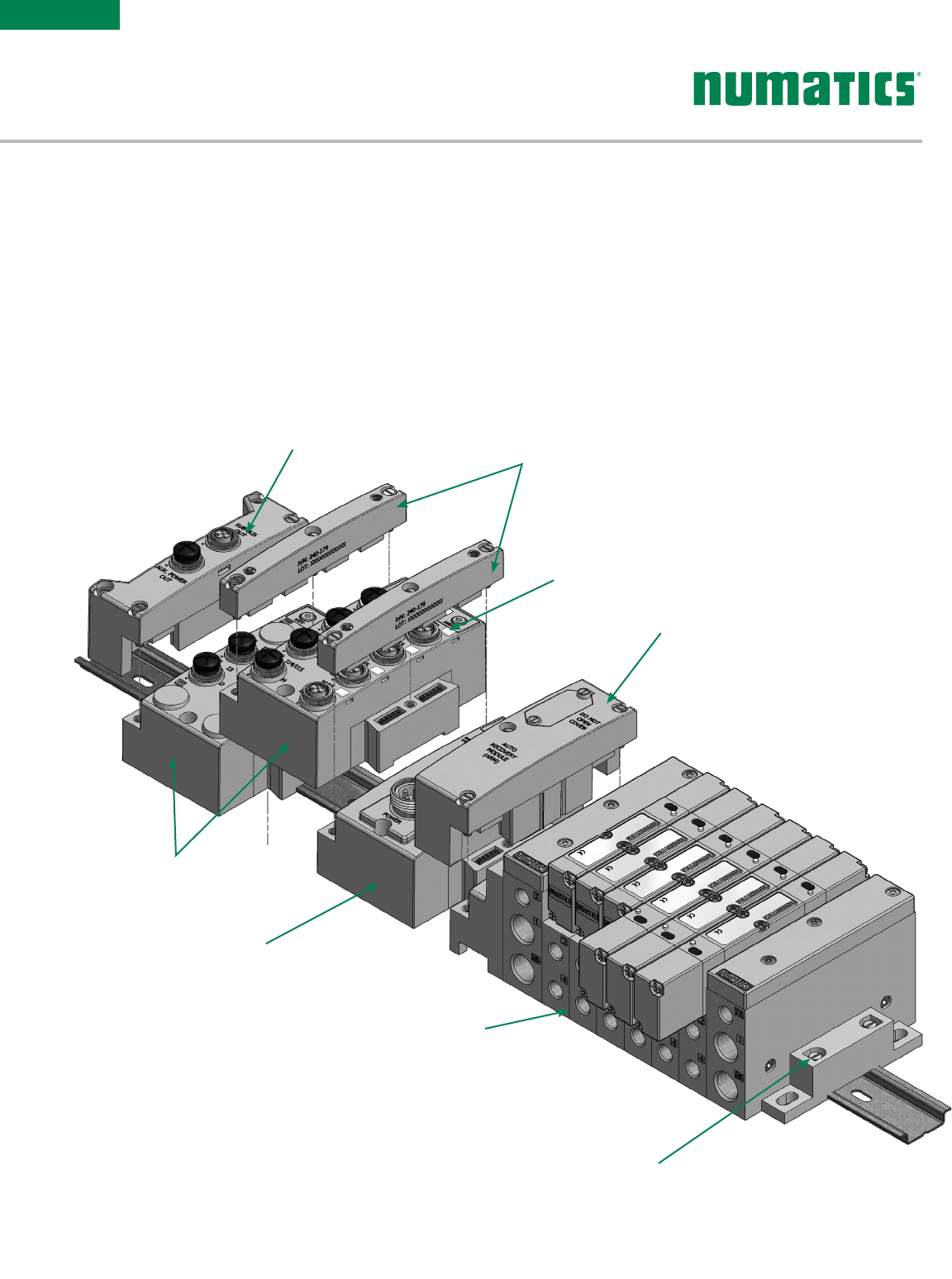
DIN Rail Mounting Option
Valve Manifold Assembly
501, 502, 503, 2002, 2005,
2012, 2035, ISO15407-2 &
ISO 5599/2 Series Valves
Communication
Module (Node)
I/O Modules-
Analog or Digital
NPN or PNP
Auto Recovery Module (ARM)
I/O Labels
Jumper Clips
Sub-Bus Out or
Terminator Module
Discrete I/O
The G3 Series product line is a completely modular system. All of the G3 electronic modules plug together, via
mechanical clips, allowing easy assembly and field changes. This makes the system highly distributable. Additional
flexibility is incorporated because the same modules can be used in either centralized or distributed applications.
The G3 electronics interfaces with the highly modular Numatics 500 Series, generation 2000 Series, ISO 5599/2
and ISO 15407-2 Series valve lines to further enhance the modularity and flexibility of the entire system.
G3 Electronics Modularity
Information subject to change without notice. For ordering information or regarding your local sales office visit www.asco.com. 21
ELECTRONICS
G3 Fieldbus
Weight
Ethernet Communications Module 255g/9 oz.
Network Data
Supported Baud Rates 10 Mbit/100 Mbit
Bus Connector D-coded 5 pin M12 type (female)
Diagnostics Power, short, open load conditions and module health are monitored
Special Features Integrated web server, fail-safe device settings, HTTP, FTP, and UNICAST (for EtherNet/IP™)
Conguration Data
Graphic Display Display used for setting IP Address, Subnet mask, Fault/Idle Actions, DHCP/BootP and all other system
settings
ARM (Auto Recovery Module) Optional module that contains automatic recovery of system setting in the event
of total or partial system failure
Maximum Valve-Solenoid Outputs 32
Maximum Addressable I/O Points Various combinations of 1200 outputs and 1200 inputs
Operating Data
Temperature Range (ambient) -23 ºC to 50 ºC (-10 ºF to 115 ºF)
Humidity 95% relative humidity, non-condensing
Vibration/Shock IEC 60068-2-27, IEC60068-2-6
Moisture Protection IP65 (with appropriate assembly and termination)
Electrical Data Voltage Current
Node Power at Max. Brightness 24 VDC +/- 10% .091 Amps
Valves & Discrete I/O 24 VDC +/- 10% 8 Amps maximum
Power Connector Single key 4 pin 7/8" MINI type (male)
Communication Connector D-coded 4 pin M12 type (female)
LEDs Module Status, Network Status and Activity/Link
Technical Data
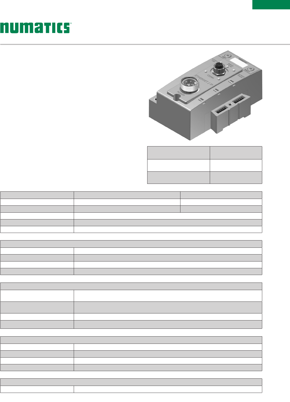
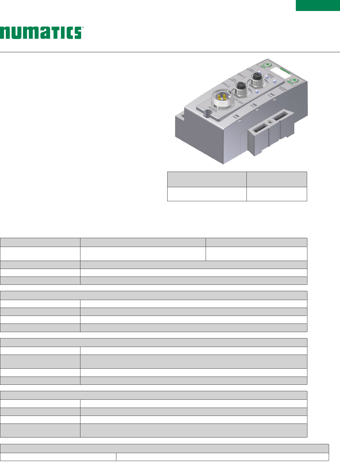
Ethernet (EtherNet/IP™ & Modbus TCP/IP)
Ethernet used throughout the world to network millions of PCs
has now evolved into a viable industrial network. Ethernet is
an open architecture high-level communication network that
meets the demands of today’s industrial applications requiring
high-speed (10/100 Mbit/s), high-throughput and flexibility.
Additionally, Ethernet technology can integrate an on-board
web server, which can make the node readily accessible to
any standard web browser for configuration, testing and even
retrieval of technical documentation.
Numatics’ G3 nodes for Ethernet have an integrated graphic
display and are capable of addressing combinations of up to
1200 outputs and 1200 inputs.
The G3 EtherNet/IP™ nodes have been tested and approved
for conformance by the ODVA.
More information about EtherNet/IP™ and the ODVA can be
obtained from the following website: www.odva.org.
Description Replacement Part
Number
EtherNet/IP™ communications
module (node) 240-181
Modbus TCP/IP communications
module (node) 240-292
Information subject to change without notice. For ordering information or regarding your local sales office visit www.asco.com.
22
ELECTRONICS
G3 Fieldbus
Weight
PROFINET® Communications Module 227g/8 oz.
Network Data
Supported Baud Rates 10 Mbit/100 Mbit
Bus Connector Two D-coded 4 pin M12 type (2-Female)
Diagnostics Power, short, open load conditions and module health and conguration are monitored
Special Features Integrated web server, Integrated 2 port switch, fail-safe device settings, and FSU
Conguration Data
Graphic Display Display used for setting IP Address, Subnet Mask, Fault/Idle Actions, and all other system settings
ARM (Auto Recovery Module) Optional module that contains automatic recovery of system setting in the event of
total or partial system failure
Maximum Valve-Solenoid Outputs 32
Maximum Addressable I/O Points Various combinations of 1200 outputs and 1200 inputs
Operating Data
Temperature Range (ambient) -23 ºC to 50 ºC (-10 ºF to 115 ºF)
Humidity 95% relative humidity, non-condensing
Vibration/Shock IEC 60068-2-27, IEC60068-2-6
Moisture Protection IP65 (with appropriate assembly and termination)
Electrical Data Voltage Current
Node Power at Max. Brightness 24 VDC +/- 10%
Valves & Discrete I/O 24 VDC +/- 10% 8 Amps Maximum
Power Connector Single key 5 pin 7/8” MINI type (male)
Communication Connector Two D-coded 4 pin M12 type (female)
LEDs Module Status, Network Status and Activity/Link
Technical Data
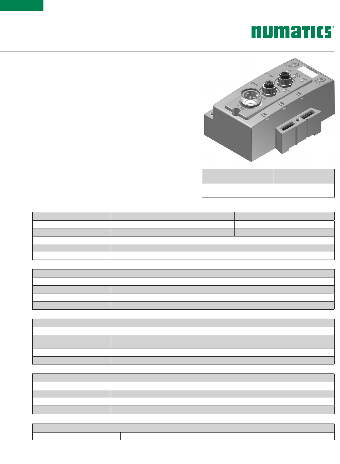
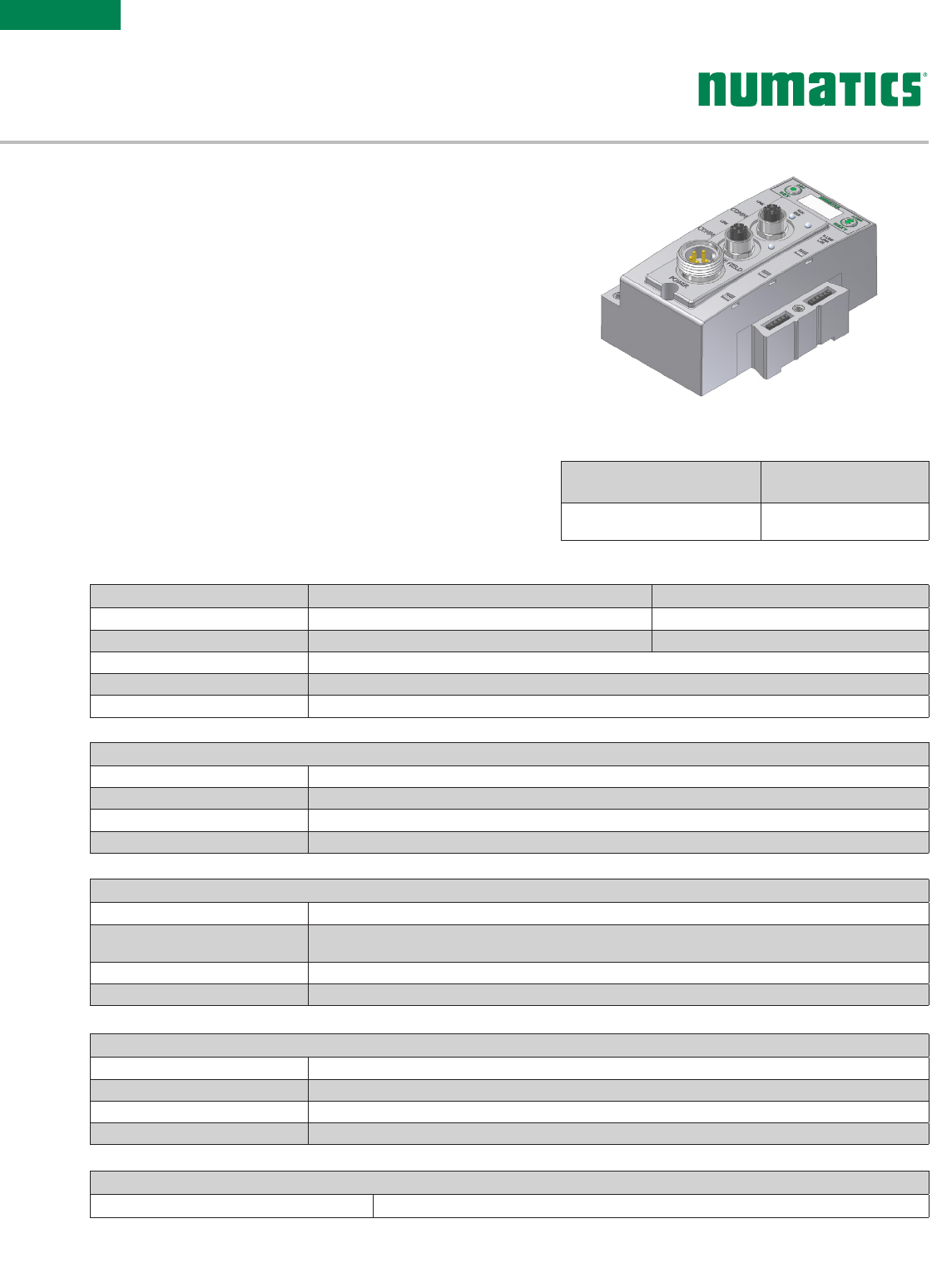
PROFINET®
PROFINET
®
is the innovative open standard for Industrial
Ethernet, developed by Siemens and the PROFIBUS
®
User
Organization (PNO). PROFINET
®
complies to IEC 61158 and IEC
61784 standards. PROFINET
®
products are certified by the PNO
user organization, guaranteeing worldwide compatibility.
Numatics’ G3 nodes for PROFINET
®
IO (PROFINET
®
RT) have
an integrated graphic display and are capable of addressing
combinations of up to 1200 outputs and 1200 inputs.
PROFINET
®
is based on Ethernet and uses TCP/IP and IT
standards and complements them with specific protocols and
mechanisms to achieve Real Time performance.
More information regarding PROFINET
®
can be obtained from
the following website: www.profibus.com.
Description Replacement Part
Number
PROFINET® communications
module (node) 240-240
Information subject to change without notice. For ordering information or regarding your local sales office visit www.asco.com. 23
ELECTRONICS
G3 Fieldbus
Weight
POWERLINK® Communications Module 227g/8 oz.
Network Data
Supported Baud Rates 10 Mbit/100 Mbit
Bus Connector Two D-coded 4 pin M12 type (2-Female)
Diagnostics Power, short, open load conditions and module health and conguration are monitored
Special Features Integrated web server, Integrated 2 port switch and fail-safe device settings
Conguration Data
Graphic Display Display used for setting IP Address, Subnet Mask, Fault/Idle Actions, and all other system settings
ARM (Auto Recovery Module) Optional module that contains automatic recovery of system setting in the event of
total or partial system failure
Maximum Valve-Solenoid Outputs 32
Maximum Addressable I/O Points Various combinations of 1200 outputs and 1200 inputs
Operating Data
Temperature Range (ambient) -23 ºC to 50 ºC (10 ºF to 115 ºF)
Humidity 95% relative humidity, non-condensing
Vibration/Shock IEC 60068-2-27, IEC60068-2-6
Moisture Protection IP65 (with appropriate assembly and termination)
Electrical Data Voltage Current
Node Power at Max. Brightness 24 VDC +/- 10%
Valves & Discrete I/O 24 VDC +/- 10% 8 Amps maximum
Power Connector Single key 5 pin 7/8” MINI type (male)
Communication Connector Two D-coded 4 pin M12 type (female)
LEDs Module Status, Network Status and Activity/Link
Technical Data
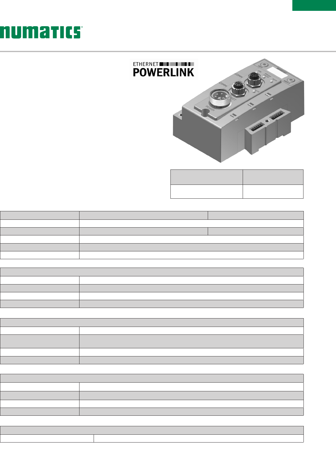
Ethernet POWERLINK®
Ethernet POWERLINK
®
is an open fieldbus
protocol designed by B&R for communication
between automation control systems and distributed I/O at the
device level.
Numatics' G3 Ethernet POWERLINK
®
nodes have an integrated
graphic display and are capable of addressing combinations of
up to 1200 outputs and 1200 inputs.
The G3 Ethernet POWERLINK
®
nodes have been designed and
tested to conform to the Ethernet POWERLINK
®
specifications
available at EPSG group (Ethernet Powerlink
®
Standardization
Group). The certification process ensures interoperability for all
Ethernet POWERLINK
®
devices and compatible with B&R systems.
More information regarding Ethernet POWERLINK
®
can be
obtained from the following website:
www.ethernet-powerlink.org.
®
Description Replacement Part
Number
POWERLINK® communications
module (node) 240-309
Description Replacement Part
Number
POWERLINK® communications
module (node) 240-309
Information subject to change without notice. For ordering information or regarding your local sales office visit www.asco.com.
24
ELECTRONICS
G3 Fieldbus
Weight
EtherCAT® Communications Module 227g /8 oz.
Network Data
Supported Baud Rates 10 Mbit/100 Mbit
Bus Connector Two D-coded 4 pin M12 type (female)
Diagnostics Power, short, open load conditions and module health and conguration are monitored
Special Features Integrated web server, fail-safe device settings
Conguration Data
Graphic Display Display used for setting IP address, Subnet Mask, Fault/Idle Actions, and all other system settings
ARM (Auto Recovery Module) Optional module that contains automatic recovery of system settings in the event of
total or partial system failure
Maximum Valve Solenoid Outputs 32
Maximum Sub-Bus I/O Points Various combinations of 1200 outputs and 1200 inputs
Operating Data
Temperature Range -23 ºC to 50 ºC (-10 ºF to 115º F)
Humidity 95% relative humidity, non-condensing
Vibration/Shock IEC 60068-2-27, IEC 60068-2-6
Moisture IP65 (with appropriate assembly and termination)
Electrical Data Voltage Current
Node Power at Max. Brightness
Valves and Discrete I/O
24 VDC +/- 10%
24 VDC +/- 10% 8 Amps Maximum
Power Connector Single key 5 pin 7/8” MINI type (male)
Communication Connector Two D-coded 4 pin M12 type (female)
LEDs Module Status, Network Status and Activity/Link
Technical Data
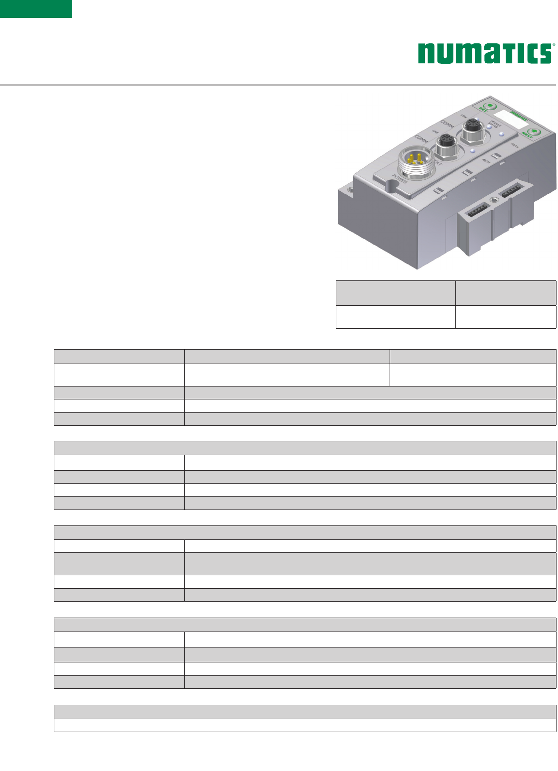
EtherCAT®
Ether CAT
®
is an open ethernet-based fieldbus protocol
developed by Beckhoff. EtherCAT
®
sets new standards
for real-time performance and topology flexibility with short
data update/cycle times and low communication jitter.
Numatics’ G3 EtherCAT
®
node has an integrated graphic
display for simplified commissioning and diagnostics. It is
capable of addressing combinations of up to 1200 outputs
and 1200 inputs.
The G3 nodes for EtherCAT
®
have been designed and
tested to conform with EtherCAT
®
specifications set forth
by the ETG.
More information regarding EtherCAT
®
can be obtained
from the following website: www.ethercat.org.
Description Replacement Part
Number
EtherCAT® communications
module (node) 240-310
Information subject to change without notice. For ordering information or regarding your local sales office visit www.asco.com. 25
ELECTRONICS
G3 Fieldbus
Weight
EtherNet/IP™ DLR Communications Module 227g/8 oz.
Network Data
Supported Baud Rates 10 Mbit/100 Mbit
Bus Connector Two D-coded 4 pin M12 type (female)
Diagnostics Power, short, open load conditions and module health and conguration are monitored
Special Features Embedded two port switch, Device Level Ring (DLR) compatibility, Linear network topology, QuickConnect™
capability, fail-safe device settings, integrated web server, HTTP, TFTP, UNICAST
Conguration Data
Graphic Display Display used for setting IP address, Subnet Mask, Fault/Idle Actions, and all other system settings
ARM (Auto Recovery Module) Optional module that contains automatic recovery of system settings in the event of
total or partial system failure
Maximum Valve Solenoid Outputs 32
Maximum Sub-Bus I/O Points Various combinations of 1200 outputs and 1200 inputs
Operating Data
Temperature Range -23 ˚C to 50 ˚C (-10 ˚F to 115˚ F)
Humidity 95% relative humidity, non-condensing
Vibration/Shock IEC 60068-2-27, IEC 60068-2-6
Moisture IP65, IP67 (with appropriate assembly and termination)
Electrical Data Voltage Current
Node Power at Max. Brightness
Valves and Discrete I/O
24 VDC +/- 10%
24 VDC +/- 10% 8 Amps Maximum
Power Connector Single key 4 pin 7/8” MINI type (male)
Communication Connector Two D-coded 4 pin M12 type (female)
LEDs Module Status, Network Status and Activity/Link
Technical Data
EtherNet/IP™ DLR
EtherNet/IP™ used throughout the world to network millions of PCs has now evolved
into a viable industry network. EtherNet/IP™ is an open architecture high-level
communication network that meets the demands of today’s industrial applications
requiring high-speed (10/100 Mbit/s), high-throughput and flexibility.
Additionally, EtherNet/IP™ technology can integrate an on-board web
server, which can make the node readily accessible to any standard
web browser for configuration, testing and even retrieval of technical
documentation.
Numatics’ G3 EtherNet/IP™ DLR (Device Level Ring) node with
integrated display has an embedded switch which allows the unit to
be used in simplified networks with linear topology configurations (daisy
chain). This technology alleviates the need for an external Ethernet switch
device in a single subnet configuration. Additionally, the DLR compatibility allows
the node to be used in a fault tolerant “ring” network, when using appropriate EtherNet/
IP™ DLR scanners. DLR configuration allows communication
recovery from a single point failure on the network ring (e.g. failed
network connection or cable).
Numatics G3 EtherNet/IP™ nodes are capable of addressing
combinations of up to 1200 outputs and 1200 inputs.
The G3 EtherNet/IP™ nodes have been tested and approved for conformance by the ODVA.
More information about EtherNet/IP™ and the ODVA can be obtained from the following website: www.odva.org.
Description Replacement Part
Number
EtherNet/IP™ DLR communications
module (node) 240-325
Information subject to change without notice. For ordering information or regarding your local sales office visit www.asco.com.
26
ELECTRONICS
G3 Fieldbus
Weight
CC-Link IE Field™ Communications Module 269g/9.5 oz.
Network Data
Supported Baud Rates 1 Gbps
Bus Connector Two D-coded 8 pin M12 type (2-Female)
Diagnostics Power, short, open load conditions and module health and conguration are monitored
Special Features Integrated 2 port switch, fail-safe device settings
Conguration Data
Graphic Display Display used for setting Node Number, Network Number, Fault/Idle Actions, and all other system settings
ARM (Auto Recovery Module) Optional module that contains automatic recovery of system setting in the event of
total or partial system failure
Maximum Valve-Solenoid Outputs 32
Maximum Addressable I/O Points Various combinations of 1200 outputs and 1200 inputs
Operating Data
Temperature Range (ambient) -23 ºC to 50 ºC (-10 ºF to 115 ºF)
Humidity 95% relative humidity, non-condensing
Vibration/Shock IEC 60068-2-27, IEC60068-2-6
Moisture Protection IP65 (with appropriate assembly and termination)
Electrical Data Voltage Current
Node Power at Max. Brightness 24 VDC +/- 10%
Valves & Discrete I/O 24 VDC +/- 10% 8 Amps Maximum
Power Connector Single key 5 pin 7/8” MINI type (male)
Communication Connector Two X-coded 8 pin M12 type (female)
LEDs Run, ERR, Link, D Link, L.ERR, L.ER
Technical Data
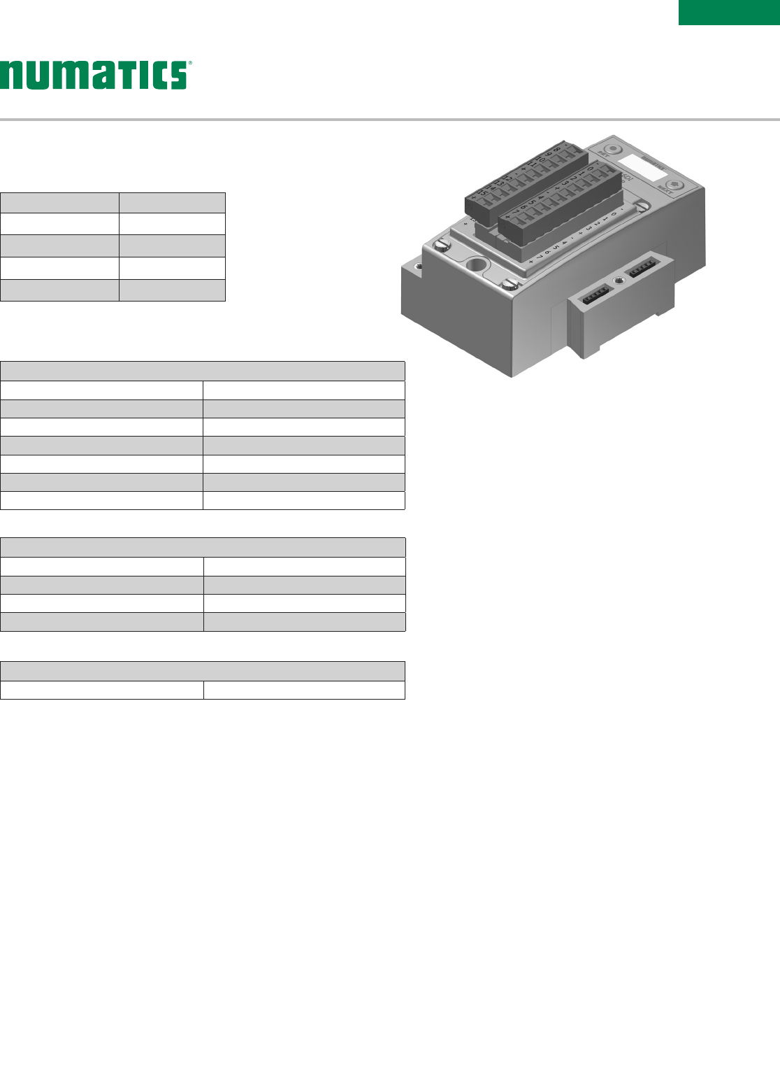
CC-Link IE Field™
CC-Link IE Field
™
is an open standard 1 Gbps Ethernet
Manufacturing network that enables seamless data
communication from the plant-level enterprise network to the
production floor network. The CC-Link Partner Association
(CLPA) oversees and manages CC-Link
®
specifications.
Numatics’ G3 nodes for CC-Link IE Field
™
have an integrated
graphic display and are capable of addressing combinations of
up to 1200 outputs and 1200 inputs.
CC-Link IE Field
™
is based on 1 Gbps Ethernet standards and
complements them with specific protocols and mechanisms to
achieve real time performance.
More information regarding CC-Link IE Field
™
can be obtained
from the following website: www.CCLinkAmerica.org
Description Replacement Part
Number
CC-Link IE Field™
communications module (node) 240-362
Information subject to change without notice. For ordering information or regarding your local sales office visit www.asco.com. 27
ELECTRONICS
G3 Fieldbus
Weight
Input Module 292g/10.3 oz.
Spare Parts
Replacement Terminal Strip (I/O 0-7) 140 -1073
Replacement Terminal Strip (I/O 8-15) 14 0 -1074
Keying Element for terminal strip 140 -1076
Keying Element for Module 140 -1077
Operating Data
Temperature Range (ambient) -23 ºC to 50 ºC (-10 ºF to 115 ºF)
Humidity 95% relative humidity, non-condensing
Vibration/Shock IEC 60068-2-27, IEC60068-2-6
Wire Range 12 to 24 AWG
Strip Length 7mm
Tightening Torque 0.5 Nm
Ingress Protection IP20
Technical Data
Description Part Number
16 PNP Inputs 240-203
16 NPN Inputs 240-204
8 PNP Inputs 240-316
16 PNP outputs 240-330
I/O Modules
Digital Inputs - Terminal Strip Modules
Information subject to change without notice. For ordering information or regarding your local sales office visit www.asco.com.
28
ELECTRONICS
G3 Fieldbus
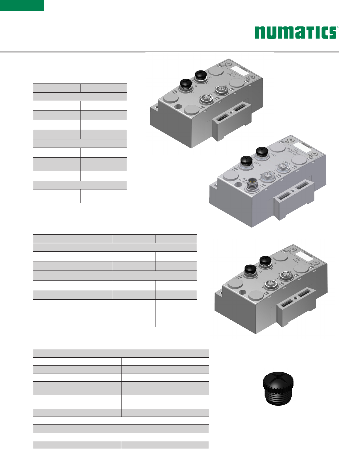
Dust Cover -
M12 Male 230-647
Figure A
Weight
I/O Module-Analog 244g/8.6 oz.
I/O Module-Digital 274 g /9.7 o z.
Operating Data
Temperature Range (ambient) -23 ºC to 50 ºC (-10 ºF to 115 ºF)
Humidity 95% relative humidity, non-condensing
Vibration/Shock IEC 60068-2-27, IEC60068-2-6
Ingress Protection IP65, IP67 (with appropriate assembly
and termination)
Connector M12 4 Pin Female, Speedcon
(Compatible with 5 Pin)
Resolution 16 bit
Technical Data
Description Signal Type Part Number
Inputs
4 Analog Inputs 0-10 VDC 240-212
4 Analog Inputs 4-20 mA 240-214
Inputs and Outputs
2 Analog Inputs & 2 Analog Outputs 0-10VD C 240-213
2 Analog Inputs & 2 Analog Outputs 4-20 mA 240-215
2 Analog Inputs & 2 Analog Outputs
High Current (Figure A Only) 0-10 VD C 240-307
4 Analog Inputs & 4 Analog Outputs
High Current (Figure A Only) 4-20 mA 240-363
Analog I/O with settable high and low alarms
5-pin M12 Modules
Description Part Number
Inputs
8 PNP Inputs 240-206
8 NPN Inputs 240-210
16 PNP Inputs 240-205
16 NPN Inputs 240-209
Outputs
8 PNP Outputs 240-208
8 PNP High Current
Outputs (Fig. A Only) 240-300
16 PNP Outputs 240-207
Inputs and Outputs
8 PNP Inputs and
8 PNP Outputs 24 0 -211
I/O Modules
Digital I/O 5-pin M12 Modules
Information subject to change without notice. For ordering information or regarding your local sales office visit www.asco.com. 29
ELECTRONICS
G3 Fieldbus
Operating Data
Temperature Range Ambient -23 ºC to 46 ºC (-10 ºF to 115 ºF)
Humidity 95% relative humidity: non-condensing
Ingress Protection IP65 (with appropriate assembly and terminations)
Mechanical Data
I/O Connector M12 4 Pin Female Speedcon (Compatible with 5 Pin)
Mass 284g/10.0 oz.
Certication
Module Marking (ATEX) II(1)GD
[Ex ia Ga] IIC [Ex ia Da] IIIC
Electrical Data
Voltage 24 VDC Module Supply
Sensor Supply = 8.2 VDC Nominal
Input Type
NC (Normally Closed)
NAMUR
Signal Current (0) ≥ 2.1 mA
Signal Current (1) ≤ 1.2 mA
Short Circuit Monitoring < 100 Ω
Open/Broken Wire Detection < 0.05 mA
Safety Parameter Output Maximums
Uo ≤ 9.6 V
Io ≤ 13 mA
Po ≤ 31 mW
Diagnostics Open (broken wire) and Short Circuit
Technical Data
240- 320 G3 [Ex ia] NAMUR Input Module
The [Ex ia] module is for use with NAMUR certified intrinsically safe (IS) sensors.
Operating Data
Temperature Range Ambient -23 ºC to 46 ºC (-10 ºF to 115 ºF )
Humidity 95% relative humidity: non-condensing
Ingress Protection IP65 (with appropriate assembly and terminations)
Mechanical Data
I/O Connector M12 4 Pin Female. Speedcon (Compatible with 5 Pin)
Mass 247g/8.7 oz.
Electrical Data
Voltage 24 VDC Module Supply (Via G3 System Aux. Power Connection)
Input Type RTD (Resistive Temperature Detector), 4 per Module
Supported Sensor Type Pt100, Pt200, Pt500, Pt1000, Ni100, Ni1000
Supported Temperature Coefcients .00385; .00392; ….Ω/Ω/°C
Resolution 15 bits plus sign
Data Format Signed Integer
Calibration Factory Calibrated Field Calibration w/high tolerance (± .005%)
100 ohm and 350 ohm resistors
Input Update (lter) Rate Adjustable (5-20mS), factory default: 5ms
Accuracy 0.1% of full scale @ 25° C
Technical Data
G3 RTD Temperature Module 240-311
The RTD module is for use with RTD (Resistive Temperature Detectors), supporting
up to four RTD devices simultaneously. The module supports various RTD types
including: Pt100, Pt200, Pt500, Pt1000, Ni100 and Ni1000.
Information subject to change without notice. For ordering information or regarding your local sales office visit www.asco.com.
30
ELECTRONICS
G3 Fieldbus
Description Part Number Weight
Jumper Clip 240 -179 45g/1.6 oz.
Jumper Clip for Intrinsically Safe 240-317 65g/2.3 oz.
Jumper Clip
Provides electrical connections between modules.
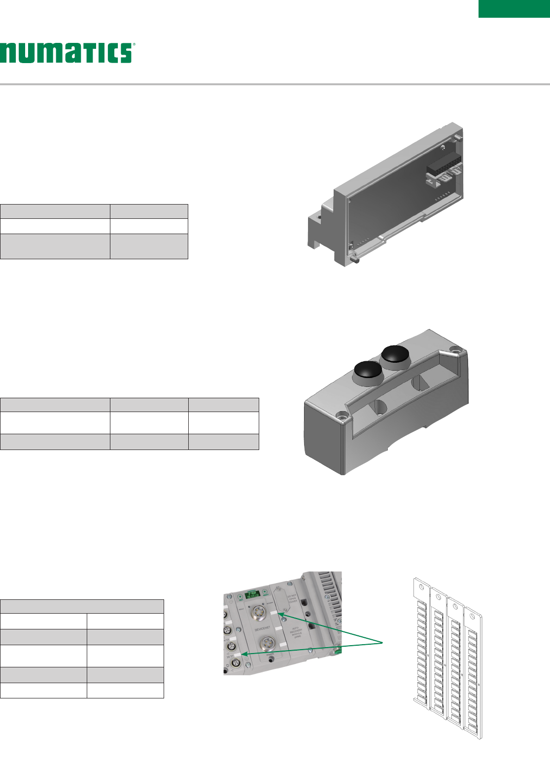
Description Part Number Weight
Terminator Module
w/DIN Rail Clips 240-245 102g/3.6 oz.
Terminator Module 24 0-184 91g/ 3.2 oz.
Terminator Module
Provides termination for the Sub-Bus. Must be installed
after the last I/O module or after the communications
module if there are no I/O modules installed.
Description Part Number Weight
ARM Module 240 -182 127g /4.5 oz.
Auto Recovery Module (ARM)
Protects configuration information during a critical failure.
Allows configuration information to be saved and reloaded
to replacement module automatically.
Miscellaneous Modules
Information subject to change without notice. For ordering information or regarding your local sales office visit www.asco.com. 31
ELECTRONICS
G3 Fieldbus
{
Technical Data
Material Polycarbonate (PC)
Color White
Temperature Range -40 ºC to 140 ºC
(-40 ºF to 284 ºF)
Label Dimensions 0.19" x 0.39"
Label - Printable Area 0.19" x 0.39"
Labels - 122-1251
Accessories
For use with Murrplastik
©
Type 20 Software.
Description Part Number Weight
Right Hand Mounting Cover
w/DIN Rail Clips 240-290 82g/2.9 oz.
Right Hand Mounting Cover 240-255 71g/2.5 oz.
* Not for use in combination with ARM Module
Right Hand Mounting Cover*
Used when a communications module is used without local
valves installed.
Description Part Number
Valve Driver Module P599AE508827001
Valve Driver Module
w/DIN Rail Clips P599AE508827002
501, 502 and 503 Series Valves
Valve Driver Module
Provides connections between the communication module or
Sub-Bus valve module and the valve manifold.
Miscellaneous Modules
Information subject to change without notice. For ordering information or regarding your local sales office visit www.asco.com.
32
ELECTRONICS
G3 Fieldbus
G
W
STR
U
V
X
YZAA
H
AD
BA
ML
N
P
Q
AB
AC
C
D
E
FJK
6.3 Wide Slot
(2) Places
Ø5.4
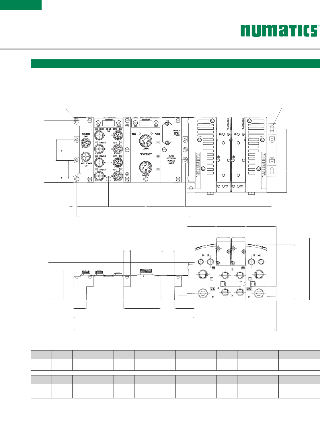
A B C D E F G H J K L M N P
105.5
(4.154)
6.3
(0.248)
38
(1.5)
52.8
(2.08)
33.8
(1.33)
7
(0.28)
5 7. 5
(2.264)
6 7. 5
(2.66)
71.7
(2.82) –3 9.1
(1.54)
75.8
(2.984)
68 .1
(2.68)
56.3
(2.217)
Q R S T U V W X Y Z*AA AB AC AD
54
(2.13)
24.8
(0.98)
6 7. 5
(2.66)
36.9
(1.45)
221.3
(8.713)
368.6
(14.51)
12.5
(0.49)
24.8
(0.976)
53
(2.087) –55.1
(2.17 )
101.1
(3.98)
112.9
(4.445)
207
(8.2)
* For valve manifold dimensions refer to Valve Series product catalogs.
503 Series Valve Manifold Assembly with G3 Electronics and Sub-Bus Output
Dimensional Drawing - G3 Fieldbus Manifold Assembly
Dimensions: mm (Inches)

Information subject to change without notice. For ordering information or regarding your local sales office visit www.asco.com. 33
ELECTRONICS
G3 Fieldbus
* Port Type '8' and 'G' only available in Port Size '3'
End Plate Port Size
3 = 3/8
4 = 1/2
K = 10mm
M = 12mm
Second Valve Series
0 = No Second Valve Series
End Plate Style
V = Vertical
Options
A00 = Standard (No Options)
MUF = Muffler in End Plates
DRM = DIN Rail Mount
DWM = DIN Rail with MUF
14X = External Pilot Supply from Port # 14
D12 = (14X) External Pilot Supply from Port #14 and (MUF)
Muffler in End Plates
D14 = (14X) External Pilot Supply from Port #14 and
(DRM) DIN Rail Mount
F06 = (14X) External Pilot Supply from Port #14, (MUF)
Muffler in End Plates, and (DRM) DIN Rail Mount
A45 = Zoned Pilot for End Plate Assembly Kit
D47 = A45 + MUF
D48 = A45 + DRM
D49 = 14X
F21 = A45 + DRM + MUF
F22 = A45 + 14X + MUF
F23 = A45 + 14X + DRM
K30 = A45 + 14X + DRM + MUF
Electronics
3 = G3 Fieldbus Electronics
Product Type
V = Valve Manifold Assembly
Revision
A = Initial Release
Product Series
503 = 26mm Valve
Port Type
8 = NPTF
*
G = ISO228/1-G
*
K = Push-in Fittings
8 503 A V 3 B 3 0 0 V A00
How to Order
Manifold Assembly
Number of Valve Stations
B = 2
D = 4
F = 6
H = 8
J = 10
L = 12
N = 14
P = 16
R = 18
T = 20
V = 22
X = 24
Z = 26
3 = 28
5 = 30
7 = 32
G3 Electronics
Left Mounting
R = w/Terminating Resistor
Modification
0 = Initial Release
Options
STD = Standard
DRM = DIN Rail Mounting
E40 = Auto Recovery Module (ARM)
G32 = E40 + DRM
Number of I/O Modules
00 = 0
01 = 1
02 = 2
03 = 3
04 = 4
05 = 5
06 = 6
07 = 7
08 = 8
09 = 9
10 = 10
11 = 11
12 = 12
13 = 13
14 = 14
15 = 15
16 = 16
Electronics Protocol
CC1 = CC-Link IE Field
EC1 = EtherCAT
ED1 = EtherNet/IP DLR
EM1 = Ethernet Modbus - TCP
EP1 = EtherNet/IP
PL1 = Ethernet POWERLINK
PN1 = PROFINET
Series
G3 = G3 Electronics
G3 EP1 00 R 0 STD
Information subject to change without notice. For ordering information or regarding your local sales office visit www.asco.com.
34
ELECTRONICS
G3 Fieldbus
Zone #2Zone #1Pilot ValvesStandard
Z
O
N
E
#
2
Z
O
N
E
#
1
P
I
L
O
T
V
A
L
V
E
S
S
T
A
N
D
A
R
D
Example Order - 503 Shown
Assembly Kit 8503AV3L300VA45
Valve Station #1 R503A2B40MA00F1
Valve Station #2 R503A2B40MA00F1
Mounting #1 8503AMM22MA0010
Valve Station #3 R503A2B10M11MF1
Accessory Station #3 K503AU516663006
Valve Station #4 R503A2B10M11MF1
Accessory Station #4 K503AU516663010
Mounting #2 8503AMS22UA010
Valve Station #5 R503A2B40MA00F1
Accessory Station #5 K503AP48330010
Valve Station #6 R503A2B40MA00F1
Mounting #3 8503AMM22X83H10
Valve Station #7 R503A2B40MA00F1
Valve Station #8 R503A2B40MA00F1
Mounting #4 8503AMM22MA0010
Valve Station #9 R503A2B40MA00F1
Accessory Station #9 K503AP48330010
Valve Station #10 R503A2B40MA00F1
Mounting #5 8503AMM22X83H10
Valve Station #11 R503A2B40MA00F1
Valve Station #12 R503A2B40MA00F1
Mounting #6 8503AMM22MA0010
Electronics G3EP100R0STD
ASSEMBLED
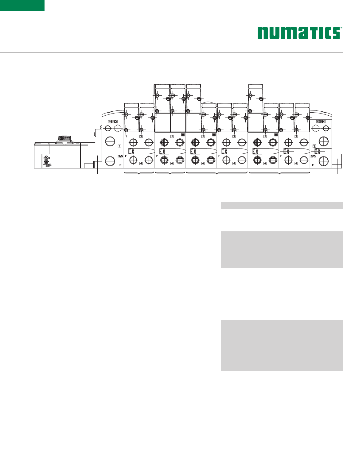
Zoned Safety manifolds can be configured with a combination of
valves for non safety related applications and up to 3 independent
safety zones. Within each safety zone both power and pilot air to
the valves can be isolated.
• Any valves that are not part of the safety related functions must be
configured starting @ Station 1
• The “U” Wiring block is the beginning of the safety zone. Only 5/2
Single Solenoid /Spring return valves without override may be used.
Each valve corresponds to a safety zone. A manifold with 2 Safety
zones will have 2 valves with the “U” Wiring
• The “X” wiring block allows 0 and +24 VDC separation for a section of
the manifold while the remainder of the manifold remains operational.
Each “X” wiring block controls up to 16 solenoids
• If Pilot Zoning is required, must select “Zoned Pilot for End Plate
Assembly Kit” in the Valve Assembly number and option “83H” Pilot
Separation for Station 1 in the Manifold Assembly Kit
• Refer to the How to Order example to the right
Ordering Zoned Safety Manifolds with G3 Electronics and 503 Valves
Information subject to change without notice. For ordering information or regarding your local sales office visit www.asco.com. 35
G3
Electronics
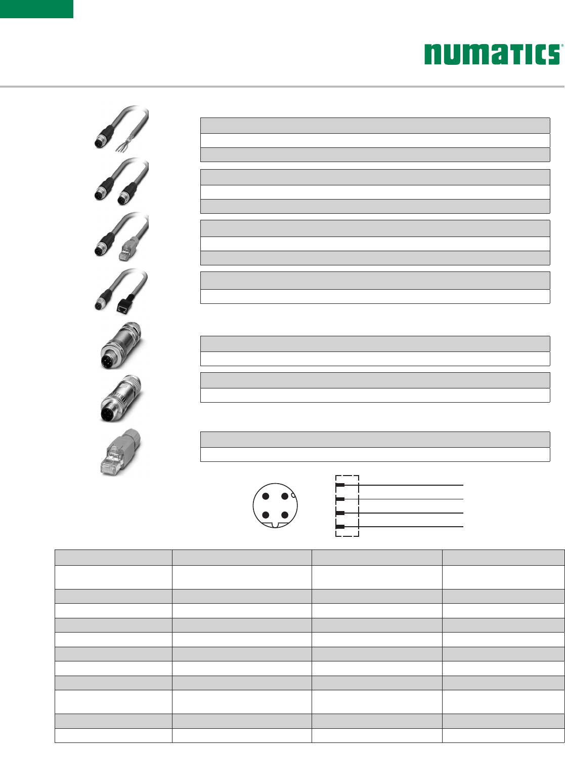
5 Pin Cables for PROFIBUS® DP, PROFINET®,
POWERLINK®, and EtherCAT®
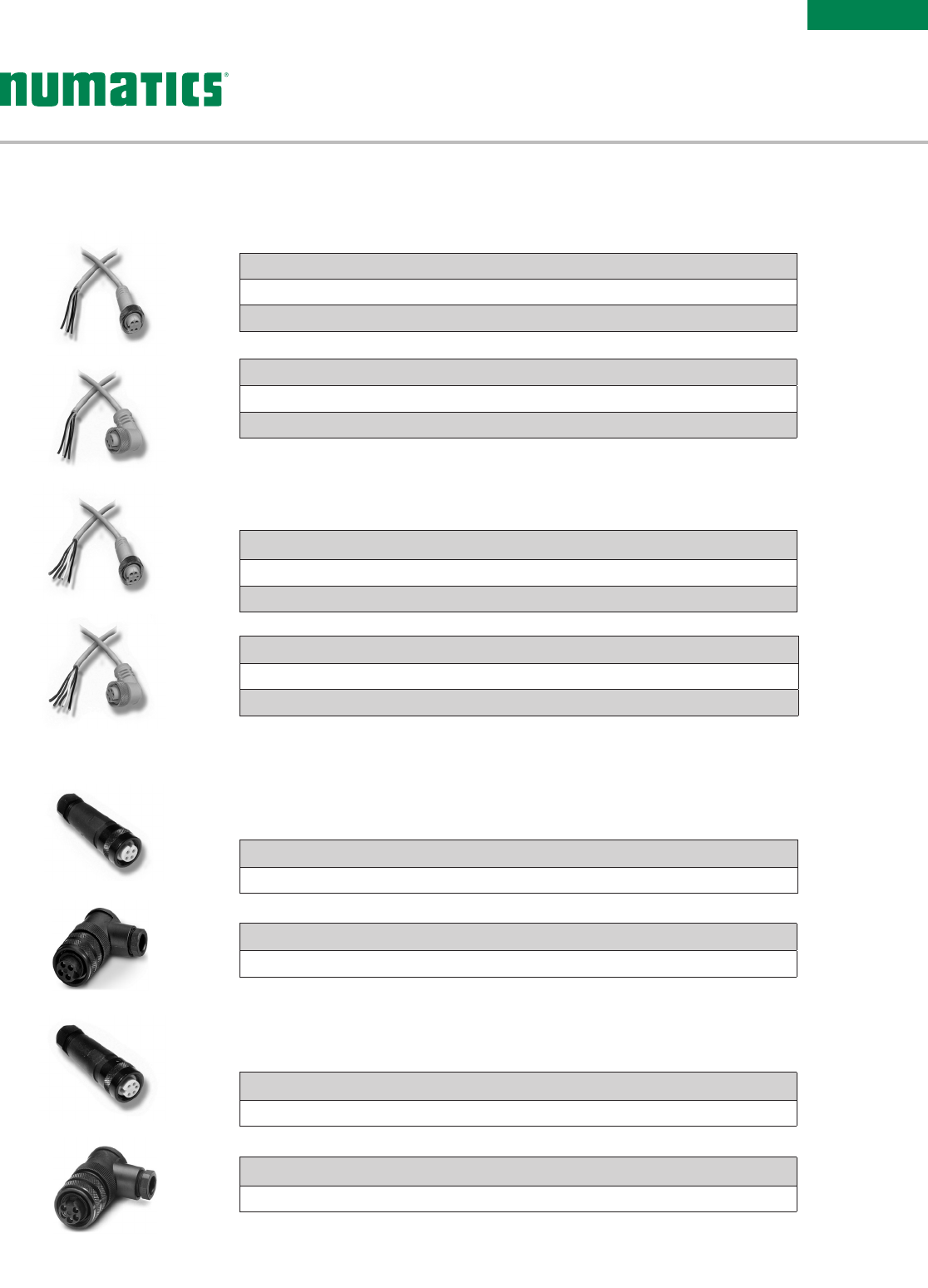
7/8" MINI 90° 5 Pin Female Field Wireable Connector
MD05F20000000000 – PG 9 Cable Gland
7/8" MINI Straight 5 Pin Female Field Wireable Connector
MC05F90000000000 – Cable Gland – One size ts all
5 Pin Connectors for PROFIBUS® DP, PROFINET® and
POWERLINK®, and EtherCAT®
7/8" MINI 90° 4 Pin Female Field Wireable Connector
MD04F20000000000 – PG 9 Cable Gland
7/8" MINI Straight 4 Pin Female Field Wireable Connector
MC04F90000000000 –Cable Gland – One size ts all
4 Pin Connectors for DeviceNet™, DeviceLogix™, Ethernet,
Modbus TCP/IP, CANopen®, and Sub-Bus
7/8" MINI Field Wireable Connectors
7/8" MINI 90° 5 Pin Female Single Ended Cable, Euro Color Code
MD0505MAG0000000 – 5 Meter
MD0510MAG0000000 – 10 Meter
7/8" MINI Straight 5 Pin Female Single Ended Cable, Euro Color Code
MC0505MAG0000000 – 5 Meter
MC0510MAG0000000 – 10 Meter
7/8" MINI 90° 4 Pin Female Single Ended Cable, Euro Color Code
MD0405MAC0000000 – 5 Meter
MD0410MAC0000000 – 10 Meter
7/8" MINI Straight 4 Pin Female Single Ended Cable, Euro Color Code
MC0405MAC0000000 – 5 Meter
MC0410MAC0000000 – 10 Meter
4 Pin Cables for DeviceNet™, DeviceLogix™, Ethernet,
Modbus TCP/IP, CANopen®, and Sub-Bus
7/8" MINI Cables
G3 POWER
CABLES & CONNECTORS
Information subject to change without notice. For ordering information or regarding your local sales office visit www.asco.com.
36
G3
Electronics
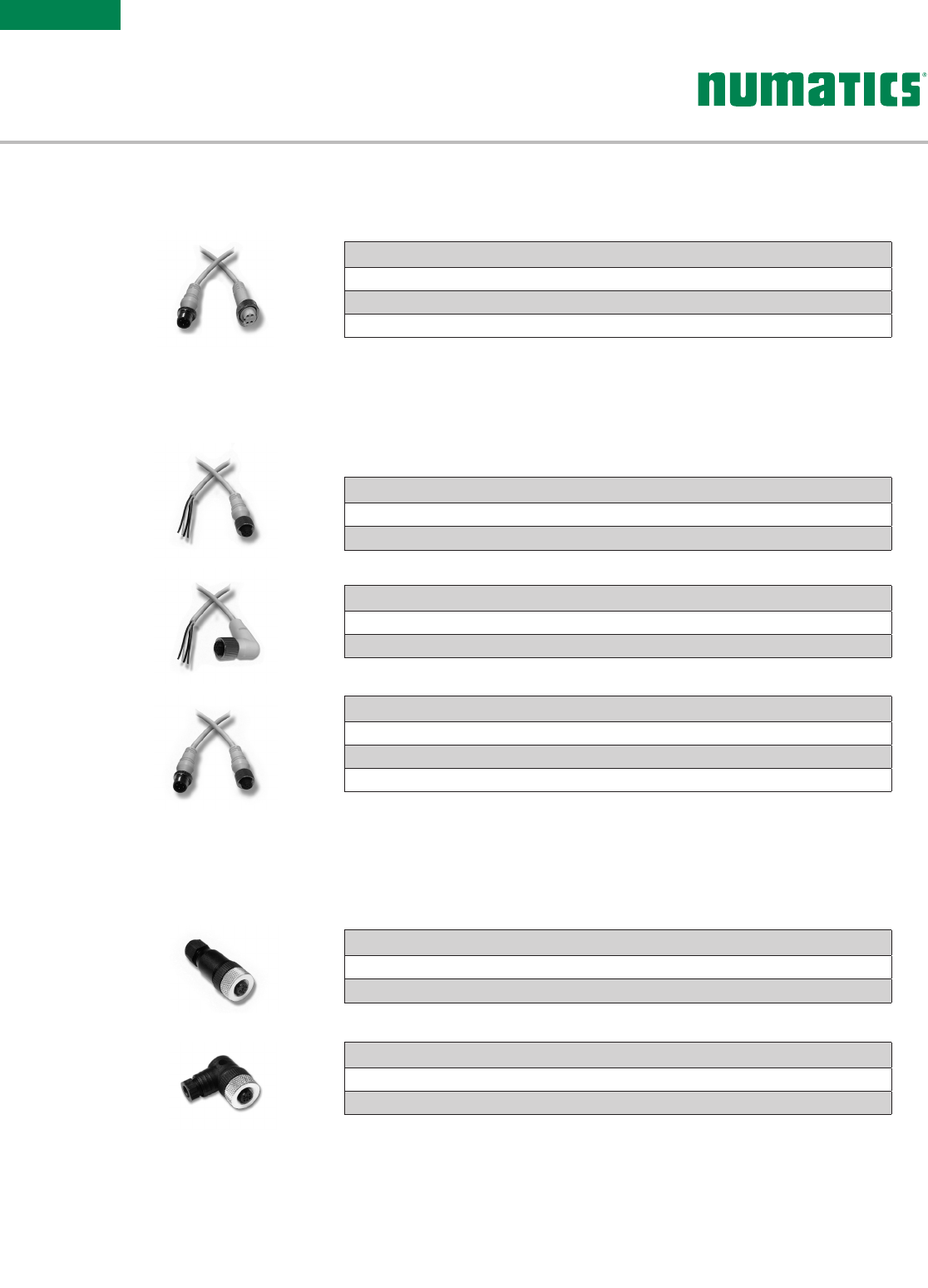
M12 90° 4 Pin Female Field Wireable Connector
TD04F10000000000 – PG 7 Cable Gland
TD04F20000000000 – PG 9 Cable Gland
M12 Straight 4 Pin Female Field Wireable Connector
TC04F10000000000 – PG 7 Cable Gland
TC04F20000000000 – PG 9 Cable Gland
4 Pin Connectors for Sub-Bus Power
M12 Field Wireable Connectors
M12 Straight 4 Pin Male to Female Cable Extension
TC0401MAETA04000 – 1 Meter
TC0405MAETA04000 – 5 Meter
TC0410MAETA04000 – 10 Meter
M12 90° 4 Pin Female Single Ended Cable, Euro Color Code
TD0405MAE0000000 – 5 Meter
TD0410MAE0000000 – 10 Meter
M12 Straight 4 Pin Female Single Ended Cable, Euro Color Code
TC0405MAE0000000 – 5 Meter
TC0410MAE0000000 – 10 Meter
4 Pin Cables for Sub-Bus Power
M12 Cables
M12 Straight 4 Pin Male to 7/8" MINI 4 Pin Female Extension
TA0401MA0MC0471T – 1 Meter
TA0405MA0MC0471T – 5 Meter
TA0410MA0MC0471T – 10 Meter
4 Pin Cable for Sub-Bus Power
M12 to 7/8" MINI Cable
Information subject to change without notice. For ordering information or regarding your local sales office visit www.asco.com. 37
G3
Electronics
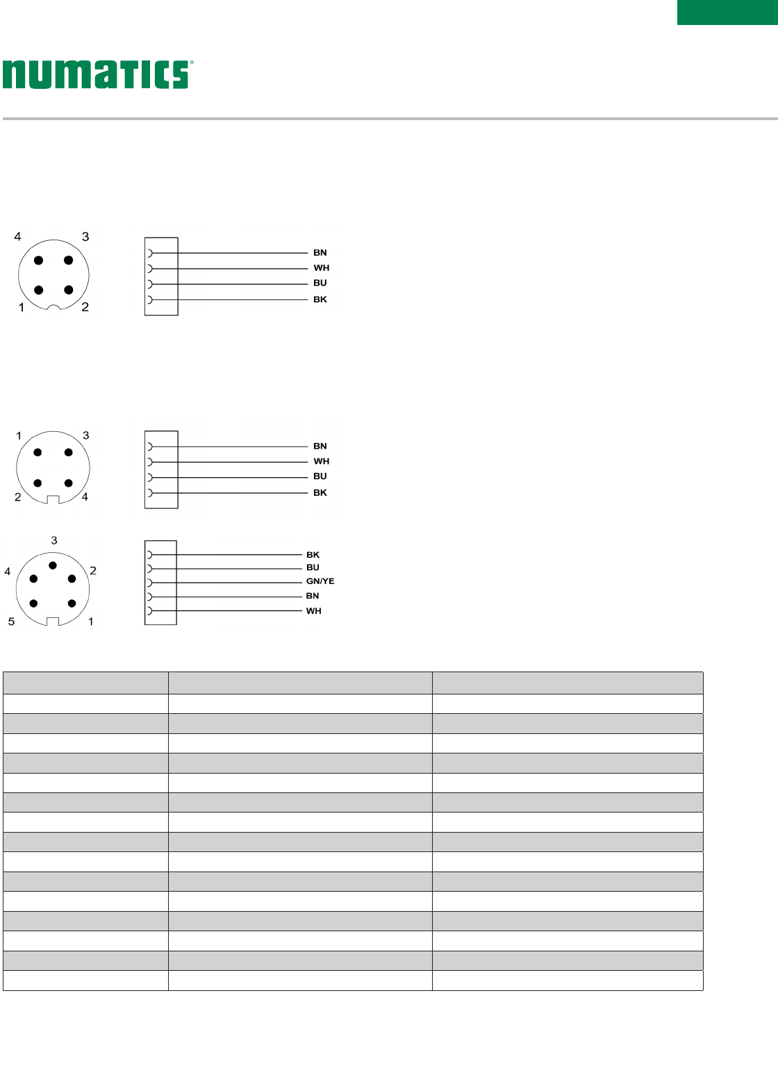
1
2
3
4
5
1
2
3
4
1
2
3
4
Technical Data M12 7/8" MINI
Molded Body/Insert Cable = PVC Field Wireable = Polyamide Cable = PVC Field Wireable = Polyamide or PBT
Coupling Nut Nickel Copper Alloy Black Anodized Aluminum/Die Cast Zinc
Cable Jacket Material PVC PVC
Cable O.D. 7. 4 m m 7.4mm (4 Pin & 5 Pin)
Voltage Rating (Nominal) 250 V Max. @ 105 °C (221 °F) 250 V Max. @ 105 °C (221 °F)
Current Rating Cables = 4.0 Amps Field Wireable = 4.0 Amps Cables = 5.5 Amps Field Wireable = 8.0 Amps
Degree of Protection IP67 (mated) IP67 (mated)
Operating Temperature -25 °C to 85 °C (-13 °F to 185 °F) -40 °C to 85 °C (-40 °F to 185 °F)
Conductor Gauge Cable = 18 AWG Cable = 18 AWG
Bend Radius Cable = 74mm Cable = 74mm (4 Pin & 5 Pin)
Maximum Wire AWG Field Wireable = 18 AWG Field Wireable = 16 AWG
Wire Connection Field Wireable = Screw Terminal Field Wireable = Screw Terminal
PG 7 Range 4-6mm N/A
PG 9 Range 6-8mm 5-13mm – One size ts all
PG 13.5 Range N/A 5-13mm – One size ts all
(Male View)
7/8" MINI Cable - Pin Out/Euro Color Code
(Male View)
M12 Cable - Pin Out/Euro Color Code
Pin Out and Technical Data
Information subject to change without notice. For ordering information or regarding your local sales office visit www.asco.com.
38
G3
Electronics
YE
WH
OG
BU
2
1
4
3
43
12
Technical Data Cable RJ45 Field Attachable M12 Field Attachable
Molded Body/Insert TPU Housing = PA Carrier = PC Body = Nickel Plated Zinc
Insert = PA 66
Coupling Nut Nickel Plated Zinc N/A Nickel Plated Brass
Cable Jacket Material PVC N/A N/A
Cable O.D. 6.5 to 7.4mm Accepts 4.5 to 8.0mm Accepts 6.0 to 8mm
Voltage Rating (Nominal) 250 Volts N/A 60 Volts
Current Rating 4.0 Amps 1.75 Amps Screw 4.0 Amps IDC 1.75 Amps
Degree of Protection IP65 (mated), RJ45 – IP20 IP20 IP 65 (mated)
Operating Temperature -25 °C to 60 °C (-13 °F to 140 °F) -10 °C to 60 °C (14 °F to 140 °F) -40 °C to 85 °C (-40 °F to 185 °F)
Conductor Gauge 22 & 24 AWG 22 AWG Solid/Stranded Screw 24-18 AWG
IDC 26-22 AWG
Bend Radius Minimum 19.5mm (xed) 45.5mm (Flexible) N/A N/A
Wire Connection NA IDC Screw Terminal, IDC
(Male View)
M12 D-Coded Cable -
Pin Out/Color Code
RJ45 Field Wireable Connector with IDC
VA08F200R000071N – PG 9 Cable Gland
RJ45 Field Attachable CONNECTOR
M12 Straight 4 Pin Male D-Coded Field Wireable Connector W/IDC
QA04F200R000071N – PG 9 Cable Gland – IDC
M12 Straight 4 Pin Male D-Coded Field Wireable Connector
QA04F20000000000 – PG 9 Cable Gland – Screw Terminal
M12 D-Coded Field Attachable CONNECTORS
M12 Straight 4 Pin Male D-Coded to RJ45 Female Socket Convertor
QA04D2MK0VC04000 – 0.2 Meter
M12 Straight 4 Pin Male D-Coded to Male RJ45 Cable
QA0405MR0VA04000 – 5 Meter
QA0410MR0VA04000 – 10 Meter
M12 Straight 4 Pin Male D-Coded Double Ended Cable
QA0405MR0QA04000 – 5 Meter
QA0410MR0QA04000 – 10 Meter
M12 Straight 4 Pin Male D-Coded Single Ended Cable
QA0405MR00000000 – 5 Meter
QA0410MR00000000 – 10 Meter
M12 D-Coded Cables
G3 PROFINET®
CABLES & CONNECTORS
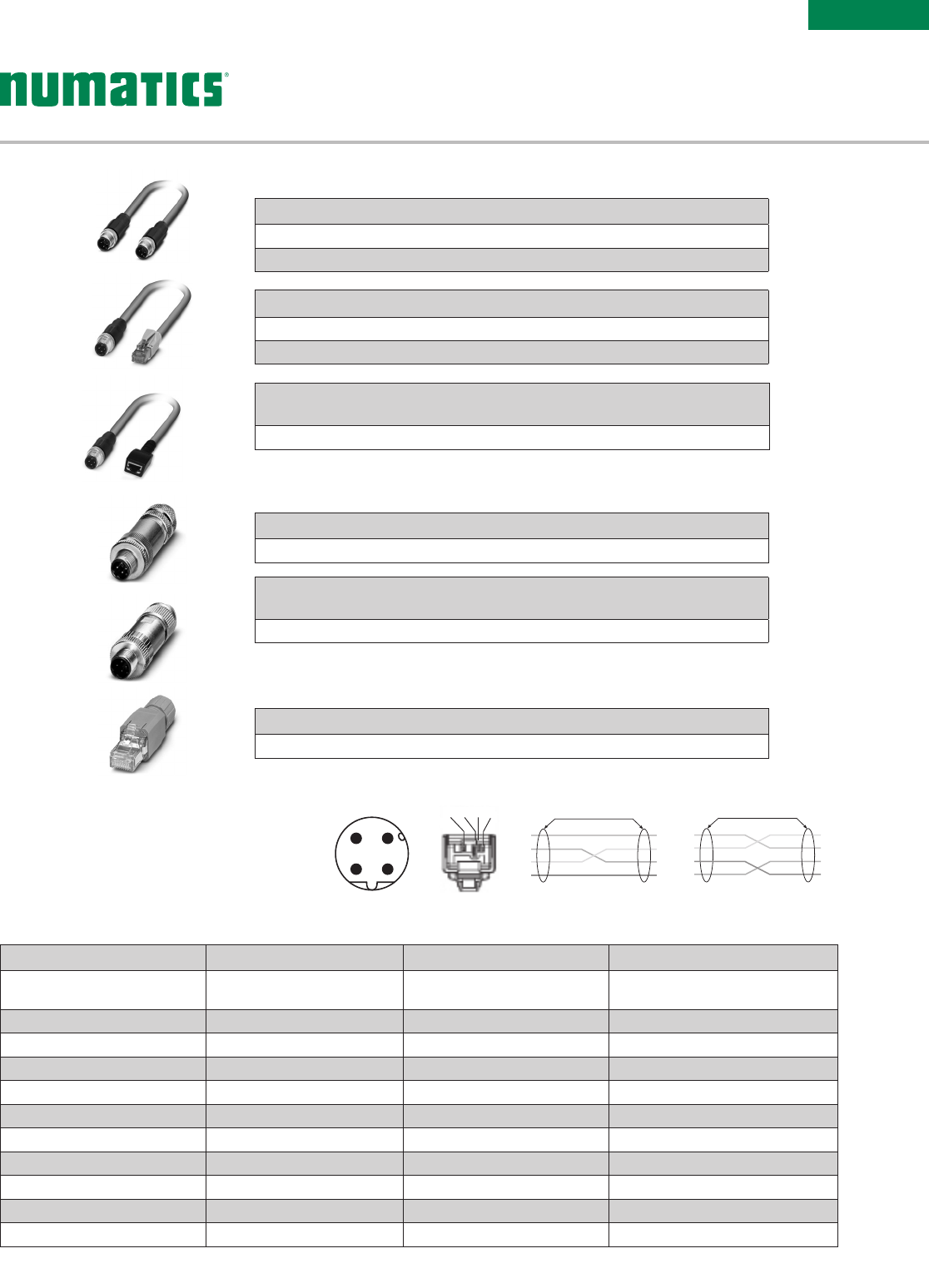
Information subject to change without notice. For ordering information or regarding your local sales office visit www.asco.com. 39
G3
Electronics
M12 to M12
1
2
3
4
1
yellow
shield
orange
white
blue
2
3
4
RJ45 to M12
1
2
3
4
1
yellow
shield
orange
white
blue
2
3
4
1234
43
12
Technical Data Cable RJ45 Field Attachable M12 Field Attachable
Molded Body/Insert N/A Housing = PA Carrier = PC Body = Nickel Plated Zinc
Insert = PA 66
Coupling Nut Nickel Plated Zinc or Brass N/A Nickel Plated Brass
Cable Jacket Material PUR N/A N/A
Cable O.D. 6.5mm Accepts 4.5 to 8.0mm Accepts 6.0 to 8mm
Voltage Rating (Nominal) N/A N/A 60 Volts
Current Rating N/A 1.75 Amps Screw 4.0 Amps IDC 1.75 Amps
Degree of Protection IP65 (mated), RJ45 – IP20 IP20 IP 65 (mated)
Operating Temperature -25 °C to 60 °C (-13 °F to 140 °F) -10 °C to 60 °C (14 °F to 140 °F) -40 °C to 85 °C (-40 °F to 185 °F)
Conductor Gauge 22 AWG 22 AWG Solid/Stranded Screw 24-18 AWG IDC 26-22 AWG
Bend Radius Minimum 45.5mm N/A N/A
Wire Connection N/A IDC Screw Terminal, IDC
(Male View)
M12 D-Coded Cable & RJ45
Pin Out/Color Code
RJ45 Field Wireable Connector with IDC
VA08F200R000071N – PG 9 Cable Gland
RJ45 Field Attachable CONNECTOR
M12 Straight 4 Pin Male D-Coded Field Wireable Connector W/
IDC
QA04F200R000071N – PG 9 Cable Gland – IDC
M12 Straight 4 Pin Male D-Coded Field Wireable Connector
QA04F20000000000 – PG 9 Cable Gland – Screw Terminal
M12 D-Coded Field Attachable CONNECTORS
M12 Straight 4 Pin Male D-Coded to RJ45 Female Socket
Converter
QA04D2MK0VC04000 – 0.2 Meter
M12 Straight 4 Pin Male D-Coded to Male RJ45 Cable
QA0405MS0VA04000 – 5 Meter
QA0410MS0VA04000 – 10 Meter
M12 Straight 4 Pin Male D-Coded Double Ended Cable
QA0405MS0QA04000 – 5 Meter
QA0410MS0QA04000 – 10 Meter
M12 D-Coded Cables
G3 POWERLINK®
CABLES & CONNECTORS
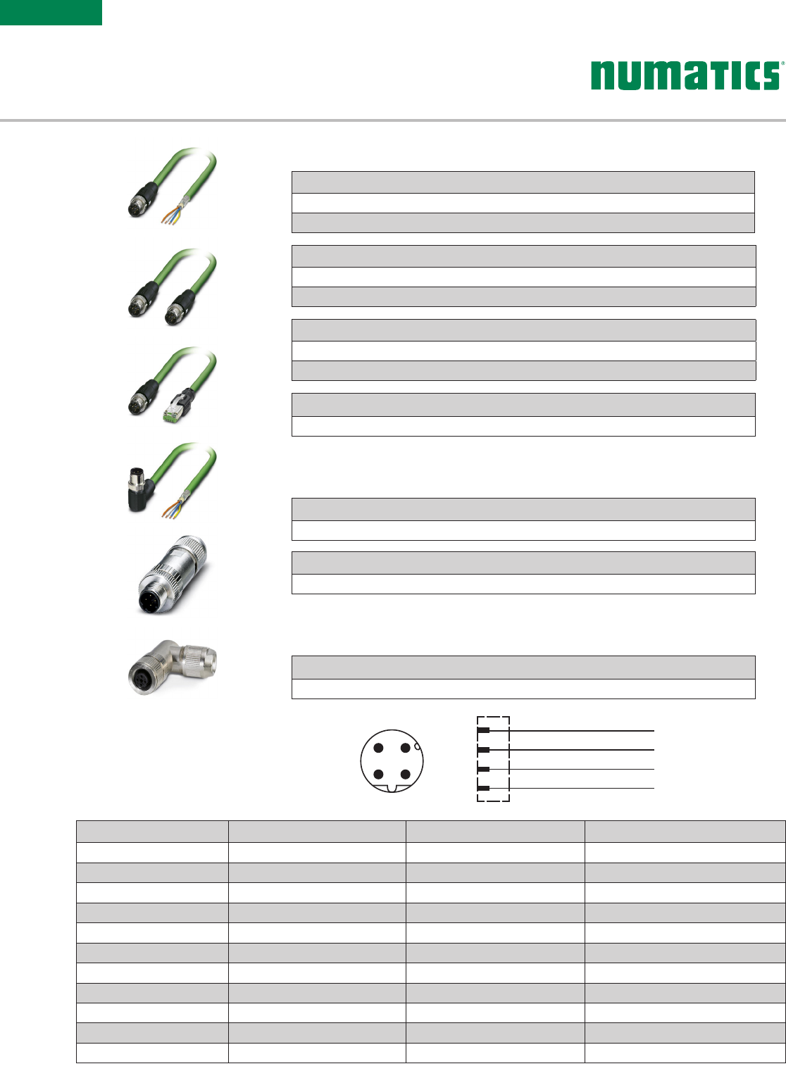
Information subject to change without notice. For ordering information or regarding your local sales office visit www.asco.com.
40
G3
Electronics
YE
WH
OG
BU
2
1
4
3
43
12
Technical Data Cable RJ45 Field Wireable M12 Field Attachable
Molded Body/Insert TPU/PE Housing = PA Carrier = PC Nickel Plated Zinc/PA 66
Coupling Nut Nickel Plated Zinc NA Nickel Plated Brass
Cable Jacket Material PVC NA NA
Cable O.D. 6.5mm Accepts 4.5 to 8.0mm Accepts 4.0 to 8mm
Voltage Rating (Nominal) 250 Volts NA 60 Volts
Current Rating 4.0 Amps 1.75 Amps Screw 4.0 Amps IDC 1.75 Amps
Degree of Protection IP65 (mated), RJ45 – IP20 IP20 IP 65 (mated)
Operating Temperature -40 °C to 70 °C (-40 °F to 158 °F) -10 °C to 60 °C (14 °F to 140 °F) -40 °C to 85 °C (-40 °F to 185 °F)
Conductor Gauge 22 & 24 AWG 22 AWG Solid/Stranded Screw 24-18 AWG IDC 26-22 AWG
Bend Radius Minimum 19.5mm (xed) 45.5mm (Flexible) NA NA
Wire Connection NA IDC Screw Terminal, IDC
(Male View)
M12 D-Coded Cable -
Pin Out/Color Code
RJ45 Field Wireable Connector with IDC
VA08F200R000071N – PG 9 Cable Gland (1658435)
RJ45 Field Attachable Connector
M12 Straight 4 Pin Male D-Coded Field Wireable Connector W/IDC
QA04F200R000071N – PG 9 Cable Gland – IDC
M12 Straight 4 Pin Male D-Coded Field Wireable Connector
QA04F20000000000 – PG 9 Cable Gland – Screw Terminal
M12 D-Coded Field Attachable Connectors
M12 Straight 4 Pin Male D-Coded to RJ45 Female Socket Convertor
QA04D2MK0VC04000 – 0.2 Meter
M12 Straight 4 Pin Male D-Coded to Male RJ45 Cable
QA0405MT0VA04000 – 5 Meter
QA0410MT0VA04000 – 10 Meter
M12 Straight 4 Pin Male D-Coded Double Ended Cable
QA0405MT0QA04000 – 5 Meter
QA0410MT0QA04000 – 10 Meter
M12 Straight 4 Pin Male D-Coded Single Ended Cable
QA0405MT00000000 – 5 Meter
QA0410MT00000000 – 10 Meter
M12 D-Coded Cables
G3 ETHERCAT® CABLES
& CONNECTORS
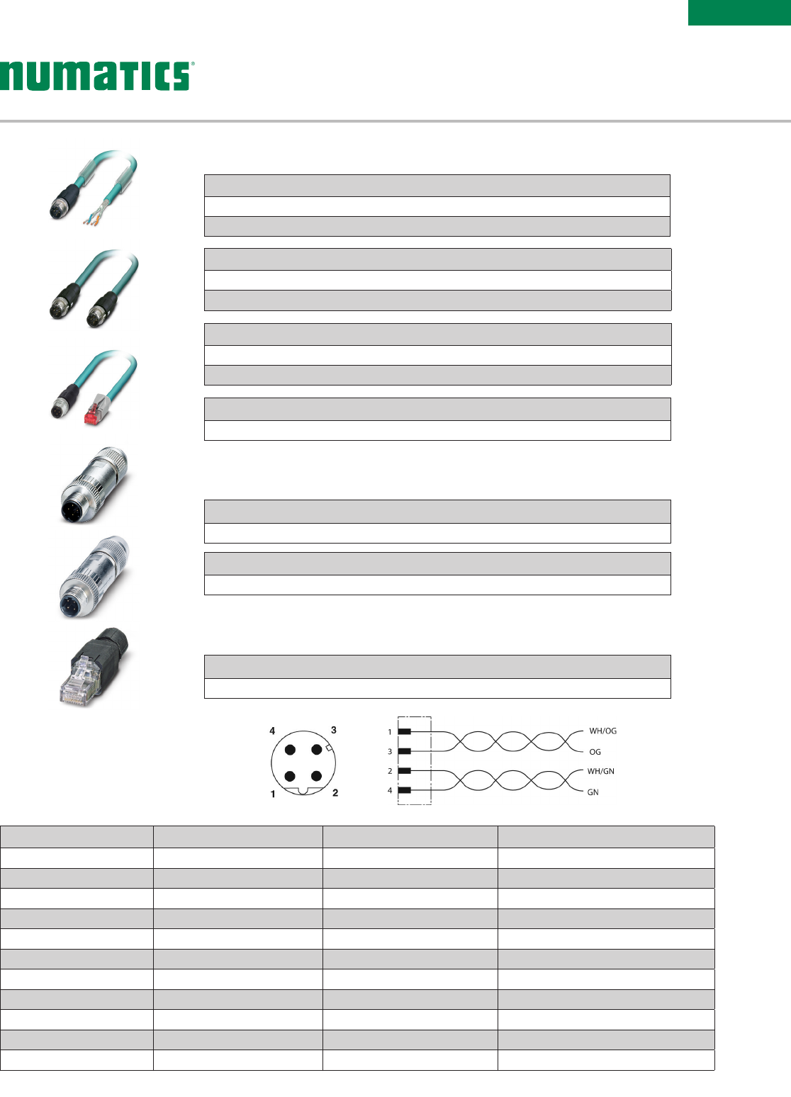
Information subject to change without notice. For ordering information or regarding your local sales office visit www.asco.com. 41
G3
Electronics
Technical Data Cable RJ45 Field Wireable M12 Field Attachable
Molded Body/Insert TPU, PA, PA66 Housing = PA Carrier = PC Body = Nickel Plated Zinc Insert = PA 66
Coupling Nut Nickel Plated Zinc or Brass NA Nickel Plated Brass
Cable Jacket Material PUR or PVC NA NA
Cable O.D. 0.67 to 8.0mm 4.5 to 8.0mm 6.0 to 8.0mm
Voltage Rating (Nominal) 42 Volts NA 60 Volts
Current Rating 1.5 Amps 1.75 Amps Screw 4.0 Amps IDC 1.75 Amps
Degree of Protection IP65 (mated) IP20 IP 65 (mated)
Operating Temperature -20 °C to 60 °C (-4 °F to 140 °F) -20 °C to 70 °C (-4 °F to 158 °F) -40 °C to 85 °C (-40 °F to 185 °F)
Conductor Gauge 26 & 24 AWG 26-22 AWG Solid/Stranded Screw 24-18 AWG IDC 26-22 AWG
Bend Radius 40mm NA NA
Wire Connection NA IDC IDC, Screw Terminal
(Male View)
M12 D-Coded Cable -
Pin Out/Color Code
RJ45 Field Wireable Connector with IDC
VA08F2000000071N – PG 9 Cable Gland
RJ45 Field Wireable Connector
M12 Straight 4 Pin Male D-Coded Field Wireable Connector
QA04F20000000000 – PG 9 Cable Gland – Screw Terminal
M12 Straight 4 Pin Male D-Coded Field Wireable Connector W/IDC
QA04F2000000071N – PG 9 Cable Gland – Screw Terminal
M12 D-Coded Field Wireable Connectors
M12 Straight 4 Pin Male D-Coded to RJ45 Female Socket Convertor
QA04D2MK0VC04000 – 0.2 Meter
M12 Straight 4 Pin Male D-Coded to Male RJ45 Cable
QA0405MK0VA04000 – 5 Meter
QA0410MK0VA04000 – 10 Meter
M12 Straight 4 Pin Male D-Coded Double Ended Cable
QA0405MK0QA04000 – 5 Meter
QA0410MK0QA04000 – 10 Meter
M12 Straight 4 Pin Male D-Coded Single Ended Cable
QA0405MK00000000 – 5 Meter
QA0410MK00000000 – 10 Meter
M12 D-Coded Cables
G3 ETHERNET/IP™-
ETHERNET/IP™ DLR &
MODBUS TCP/IP CABLES
& CONNECTORS
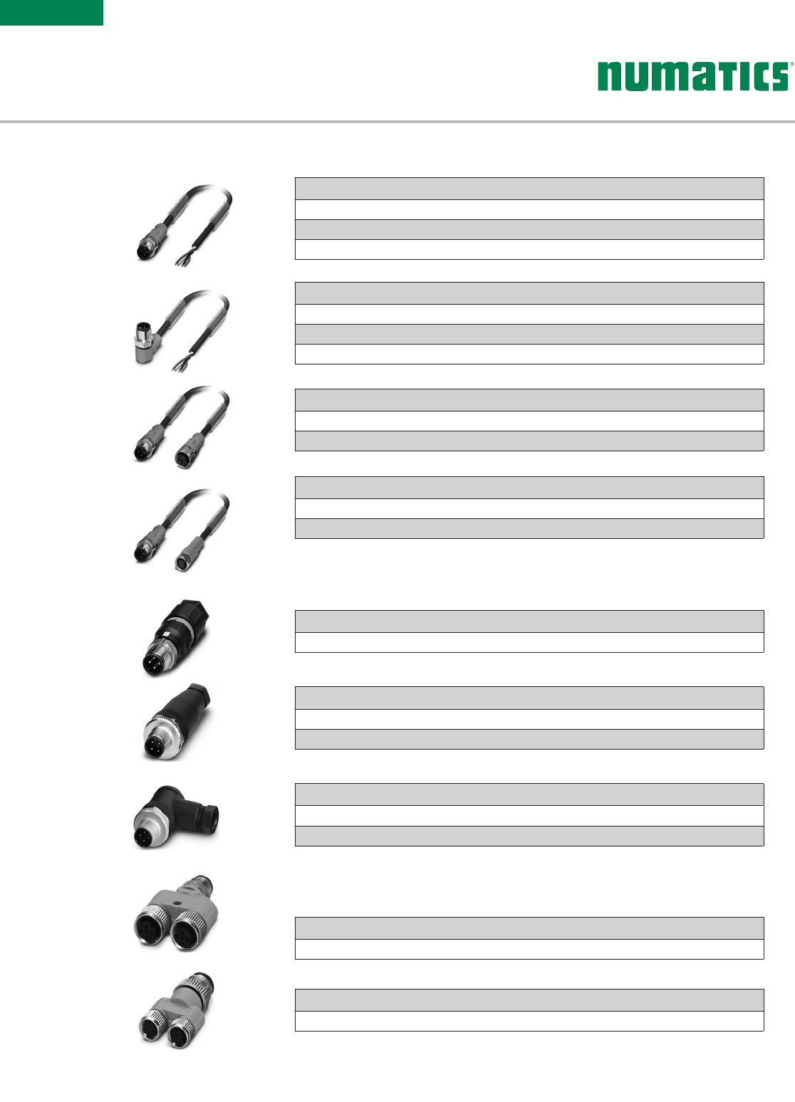
Information subject to change without notice. For ordering information or regarding your local sales office visit www.asco.com.
42
G3
Electronics
M12 to M8 “Y” Splitter
TA0400000KC03000
M12 to M12 “Y” Splitter, 21mm Spacing
TA0500000JC05000
I/O Splitters
M12 90° 4 Pin Male Field Wireable Connector, Screw Terminal
TB04F10000000000 – PG 7 Cable Gland
TB04F20000000000 – PG 9 Cable Gland
M12 Straight 4 Pin Male Field Wireable Connector, Screw Terminal
TA04F10000000000 – PG 7 Cable Gland
TA04F20000000000 – PG 9 Cable Gland
M12 Straight 4 Pin Male Field Wireable Connector, IDC Connection
TA04F2000000081E – PG 9 Cable Gland w/SPEEDCON® connector technology
I/O Connectors
M12 Straight 3 Pin Male to M8 3 Pin Straight Female Extension
TC03E5MIEPA0371P – 1.5 Meter
TC0303MIEPA0371P – 3 Meter
M12 Straight 4 Pin Male to Female Cable Extension
TC04E5MIETA0471P – 1.5 Meter
TC0403MIETA0471P – 3 Meter
M12 90° 4 Pin Male Single Ended Cable, Euro Color Code
TB04E5MIE000071P – 1.5 Meter
TB0403MIE000071P – 3 Meter
TB0405MIE000071P – 5 Meter
M12 Straight 4 Pin Male Single Ended Cable, Euro Color Code
TA04E5MIE000071P – 1.5 Meter
TA0403MIE000071P – 3 Meter
TA0405MIE000071P – 5 Meter
I/O Cables with SPEEDCON® Connector Technology
G3 I/O CABLES
& CONNECTORS
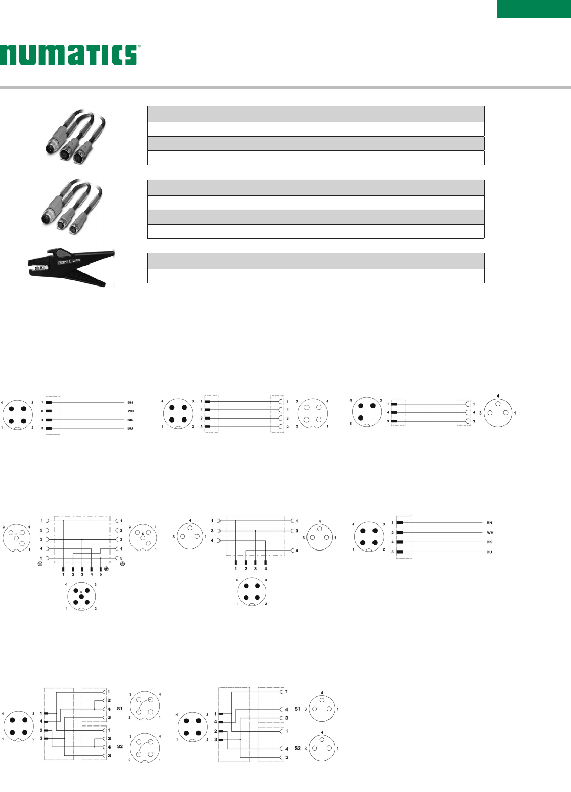
Information subject to change without notice. For ordering information or regarding your local sales office visit www.asco.com. 43
G3
Electronics
NOTE:
XX denotes allowable length.
See pages 42 & 43.
M12 to M8 Cable Splitter - Pin Out
TA04XXMIEKC03000
(Male to Female View)
M12 to M12 Cable Splitter - Pin Out
TA04XXMIEJC04000
(Male to Female View)
M12 Field Wireable (IDC) - Pin Out
TA04F2000000081E (SPEEDCON
®
)
(Male View)
M12 to M8 "Y" Splitter - Pin Out
TA0400000KC03000
(Male to Female View)
M12 to M12 "Y" Splitter - Pin Out
TA0500000JC05000
(Male to Female View)
M12 Cable - Pin Out/Color Code
TC03XXMIEPA0371P
(Male to Female View)
M12 Cable - Pin Out/Color Code
TC03XXMIEPA0371P
(Male to Female View)
M12 Cable - Pin Out/Color Code
TA04XXMIE0000000,
TB04XXMIE0000000
(Male View)
I/O Cable Connector Pin Out Diagrams
Wire Stripper Tool
140 -10 97
M12 Cable Splitter, 2 Straight M8 Female Connectors
TA04D3MIEKC03000 – 0.3 Meter
TA04E5MIEKC03000 – 1.5 Meter
TA0403MIEKC03000 – 3.0 Meter
M12 Cable Splitter, 2 Straight M12 Female Connectors
TA04D3MIEJC04000 – 0.3 Meter
TA04E5MIEJC04000 – 1.5 Meter
TA0403MIEJC04000 – 3.0 Meter

Information subject to change without notice. For ordering information or regarding your local sales office visit www.asco.com.
44
G3
Electronics
Technical Data Wire Stripper
Use with PVC Insulation
Stripping Range 28 AWG to 10 AWG
Cutting Range (Flexible) 10 AWG
Cutting Range (Rigid) 12 AWG
Technical Data I/O "Y" Splitter I/O Cable Splitter
Molded Body/Insert TPU TPU
Coupling Nut Nickel Plated Zinc Nickel Plated Zinc
Cable Jacket Material NA PUR
Cable O.D. NA 4.40mm
Voltage Rating 60 Volts 60 Volts
Current Rating (Cond.) 3.0 Amps 3.0 Amps
Degree of Protection IP67 (mated) IP67 (mated)
Operating Temperature -25 ºC to 90 ºC (-13 °F to 194 °F) -25 ºC to 80 ºC (-13 °F to 176 °F)
Conductor Gauge NA 22 AWG or 24 AWG
Bend Radius NA 44mm
Technical Data M12 Cables M12/M8 Cables M12 Connectors
Molded Body/Insert TPU TPU Polyamide (or) PA 66
Coupling Nut Nickel Plated Zinc Nickel Plated Zinc Nickel Plated Zinc
Cable Jacket Material PUR PUR NA
Cable O.D. 4.70mm 4.70mm PG7 4.0 to 6.0mm
PG9 4.0 to 8.0mm
Voltage Rating 250 Volts 60 Volts 50 Volts
Current Rating (Cond.) 4.0 Amps 3.0 Amps 4.0 Amps
Degree of Protection IP65 (mated) IP65 (mated) IP67 (mated)
Operating Temperature -25 ºC to 80 ºC (-13 °F to 176 °F)
(xed instl.)
-25 ºC to 80 ºC (-13 °F to 176 °F)
(xed instl.) -25 ºC to 80 ºC (-13 °F to 176 °F)
Conductor Gauge 22 AWG 22 AWG 22 AWG Min. 18 AWG Max.
Bend Radius 47mm 47mm NA
Cable and Connector Technical Data

Information subject to change without notice. For ordering information or regarding your local sales office visit www.asco.com. 45
NOTES
SERIES
503

Information subject to change without notice. For ordering information or regarding your local sales office visit www.asco.com.
46
NOTES
SERIES
503

Numatics® is registered in the United States and elsewhere
LT-503ZSeries Rev 05/16
10M-Walsworth-09/12
© Numatics Inc. 2012-2016
Numatics, Inc. | Tel (248) 596-3200 | www.asco.com | email: an.insidesales@emerson.com
Brazil - Ascoval Ind.e Comercio Ltda
P: (55) 11-4208-1700
F: (55) 11-4195-3970
México - Ascomatica SA de CV
P: 52 55 58 09 56 40 (DF y Area metropolitana)
P: 01 800 000 2726 (Interior de la República)
F: 52 55 58 09 56 60
Canada - Numatics, Ltd
P: 519-758-2700
F: 519-758-5540
USA - Numatics, Incorporated
46280 Dylan Drive
Novi, Michigan 48377
P: 248-596-3200
F: 248-596-3201
World Headquarters
