Flow Numatics E Series Specialty Cylinder 1505482699 User Manual
Numatics E Series Specialty Cylinder-1505482699 NUMATICS_E_SERIES_SPECIALTY_CYLINDER-1505482699
2017-10-06
User Manual: Flow Numatics E Series Specialty Cylinder-1505482699
Open the PDF directly: View PDF ![]() .
.
Page Count: 26
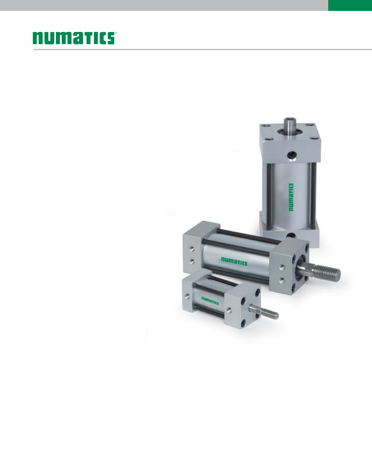
E Series
Economic Tie-Rod Cylinder Line
www.numatics.com

E Series
Features and Benefits 3
How to Order 4
Basic E-Series Cylinders 5
Cushioned Cylinders 5
Basic E-Series Dimensions 5
E-Series Rod Ends 6
Piston Rod Ends 6
Standard and Optional Rod Ends 7
E-Series Double Rod Dimensions 7
Bottom Tapped Mount 8-9
Clevis and Eye Mounts 10
End Lug Mount 11
Trunnion Mounts 12
Accessories 13
How to Order - E Series Piston Rod Assembly 14
How to Order - E Series Repair Kit 15
How to Order - E Series Seal Kit 15
Piston Rod Assembly Kit Installation Instructions 16
Seal Installation Guide 16
Diagrams 17
Repair Kit Removal/Installation Instructions 18
Seal Kit Removal/Installation Instructions 19
World Switches 20-21
Specialty Cylinders 21
Sensing Part Numbers 22-24
Quick Disconnect Cables 25
Table of Contents
Information subject to change without notice. For ordering information or regarding your local sales office visit www.numatics.com.
3
E
SERIES
The E Series is a cost-efficient cylinder line that is ideal for a variety of OEM applications, providing long-lasting and reliable service.
Tube
The file hard (60RC) high strength aluminum alloy tube provides a
smooth corrosion free sealing surface and excellent abrasion resistance.
End Caps
The end caps are accurately machined from (6061-T6) solid
aluminum bar stock. They are anodized for corrosion resistance.
Additionally, a recess on the piston-mating surface (at both ends) enables
the air to work on a larger piston area for effortless breakaway.
Rod Bushing
The cast iron rod bushing provides maximum load bearing support. This
graphite filled material offers the best bearing surface with hard chrome
plated piston rod.
Rod seal and wiper
The rod seal and wiper are made from a highly durable material for
long-lasting service.
Piston rod
High strength steel piston rod has a ground, polished and hard chrome
plated surface providing maximum life of bushing and seals.
Bushing retainer
The bushing retainer allows cartridge removal without disassembly.
Tie Rods
Tie rods are 100,000 psi minimum yield steel for maximum holding
power. Tie rod threads are rolled for strength and engagement.
Piston seals
The piston seals are a Buna-N lip seals that provides smoother
breakaway.
Wear band
The extra wide wear band is provided to support maximum loading.
Piston
The solid aluminum alloy piston is strong and lightweight.
Tube seals
The tube seals are compression type and reusable.
The floating cushion seal design gives the fastest stroke reversal possible
by providing instantaneous full flow to piston. Each cushion has a flush,
retained adjustment needle.
Information subject to change without notice. For ordering information or regarding your local sales office visit www.numatics.com.
4
E
SERIES
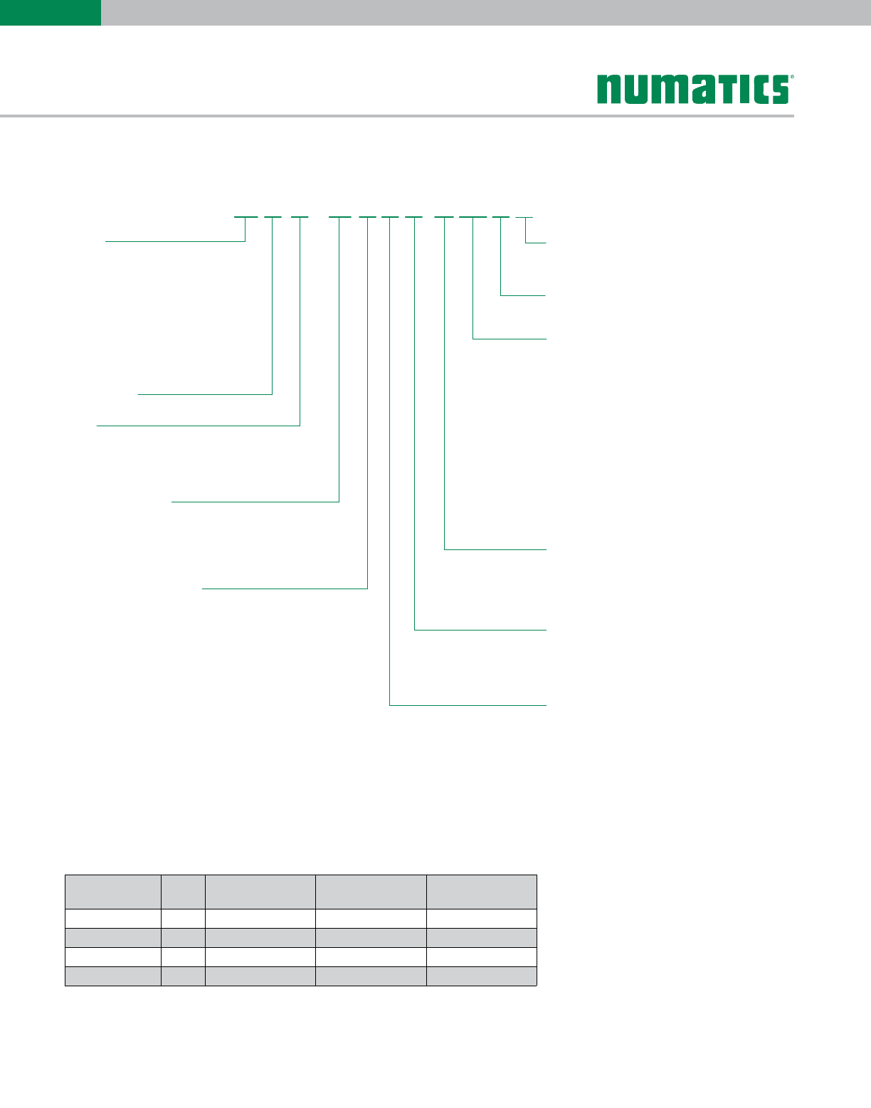
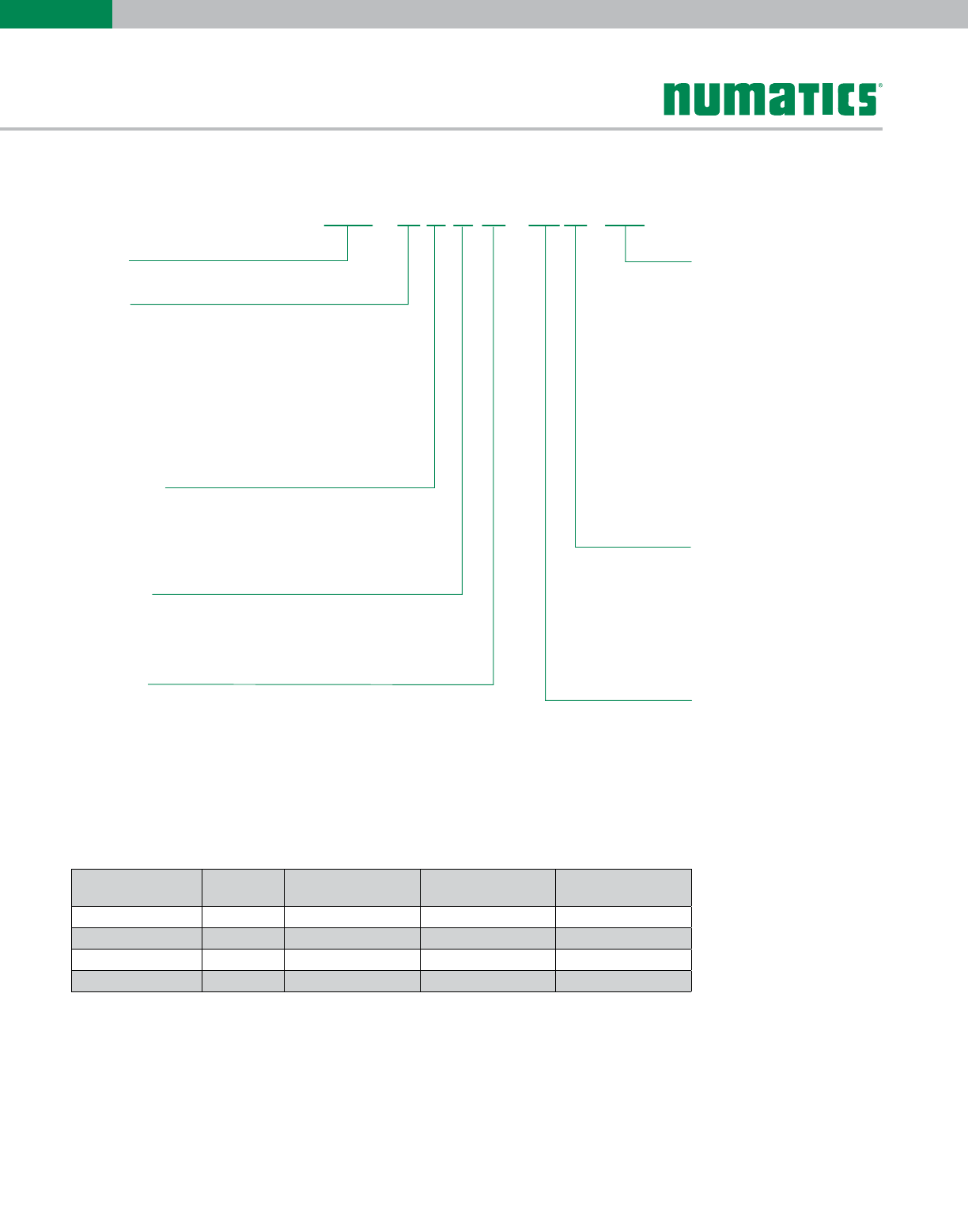
E Series Cylinder - How to Order
Mount
F1 =Front Flange
F2 = Rear Flange
P2 = Detachable Clevis
P4 = Detachable Eye
P7 = P2 and S4 Mount Combination
S4 = Bottom Tapped
S7 = End Lug
T1 = Head Trunnion
T2 = Cap Trunnion
T4* = Mid Trunnion Fixed
X0=No Mount
*Specify "XI" length.
Cylinder Type
EType "E" Cylinder
Bore
F 1-1/4"
I 1-3/4"
L2"
M
=
=
=
=
= 2-1/2"
N3"=
Q 3-1/2"
S 4-1/2"
T5"
U
=
=
=
=6"
W8"=
Full Inches of Stroke
00 = 0" Stroke
01 = 1" Stroke
02 = 2" Stroke
03 = 3" Stroke
99 = 99" Stroke
Fractional Inches of Stroke
A0"I1/2"
B 1/16" J 9/16"
C 1/8" K 5/8"
D 3/16" L 11/16"
E 1/4" M 3/4"
F 5/16" N 13/16"
G 3/8" O 7/8"
H
=
=
=
=
=
=
=
= 7/16" P
=
=
=
=
=
=
=
= 15/16"
P2 EL A1CCAA 0
04
Magnet
0 No Magnet
2
=
= Reed Magnet
Options
AA = No Options
BA**= Bumpers, Both Ends
BC**= Bumpered Cap End
BH**= Bumpered Head End
KA = Stroke Adjuster
DA = Double Rod End
MA = Metallic Rod Scraper
NA = Nickel Plated Cylinder
SA = Stainless Steel Rods
ST = Stainless Steel Rods and Tie Rods
VA = FKM Seals
1A* = Rod Extension
2A* = Thread Extension
3A = Studded Rod End
4A* = Stop Tube
**Bumpers add .062" to OAL (per bumper)
*Must specify length.
Cushions
Position 1234
No Cushion AAAA
Head and Cap BCDE
Head Only FG J
Cap Only KL
H
MN
Ports
Position 1/8" 1/4" 3/8"
1C
2I
3
B
H
NO
4TU
D
J
P
V
1/2" 3/4"
E
K
Q
W
F
L
R
X
Rod End Codes
1 Style #1 Standard Rod Diameter
2 Style #2 Standard Rod Diameter
3 Style #3 Standard Rod Diameter
4=Special Threads, Standard Rod Diameter
(must specify threads)
=
=
=
-- B
Port Modifications (Only on 1-1/4" Bore)
B = Port Modified
Note: Leave Blank if
No Port Modifications
Piston Rod Ends
Bore Rod
Dia.
Style #1
(Male Thread)
Style #2
(Male Thread)
Style #3
(Female Thread)
1-1/4 0.375 3/8-16 1/4-20 1/4-20
1-3/4, 2, 2-1/2, 3 0.750 3/4-10 1/2-13 1/2-13
3-1/2, 4-1/2, 5 1.000 1-8 3/4-10 3/4-10
6, 8 1.500 1 1/4-12 1-8 1 1/4-12
Example order:
Part Number: P2EL-04A1C-CAA0
Information subject to change without notice. For ordering information or regarding your local sales office visit www.numatics.com.
5
E
SERIES
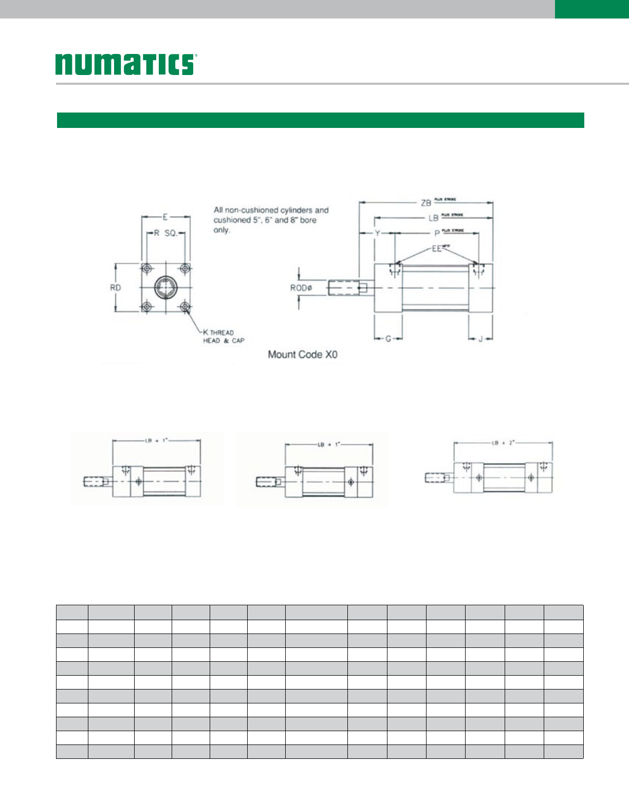
Basic E-Series Cylinders
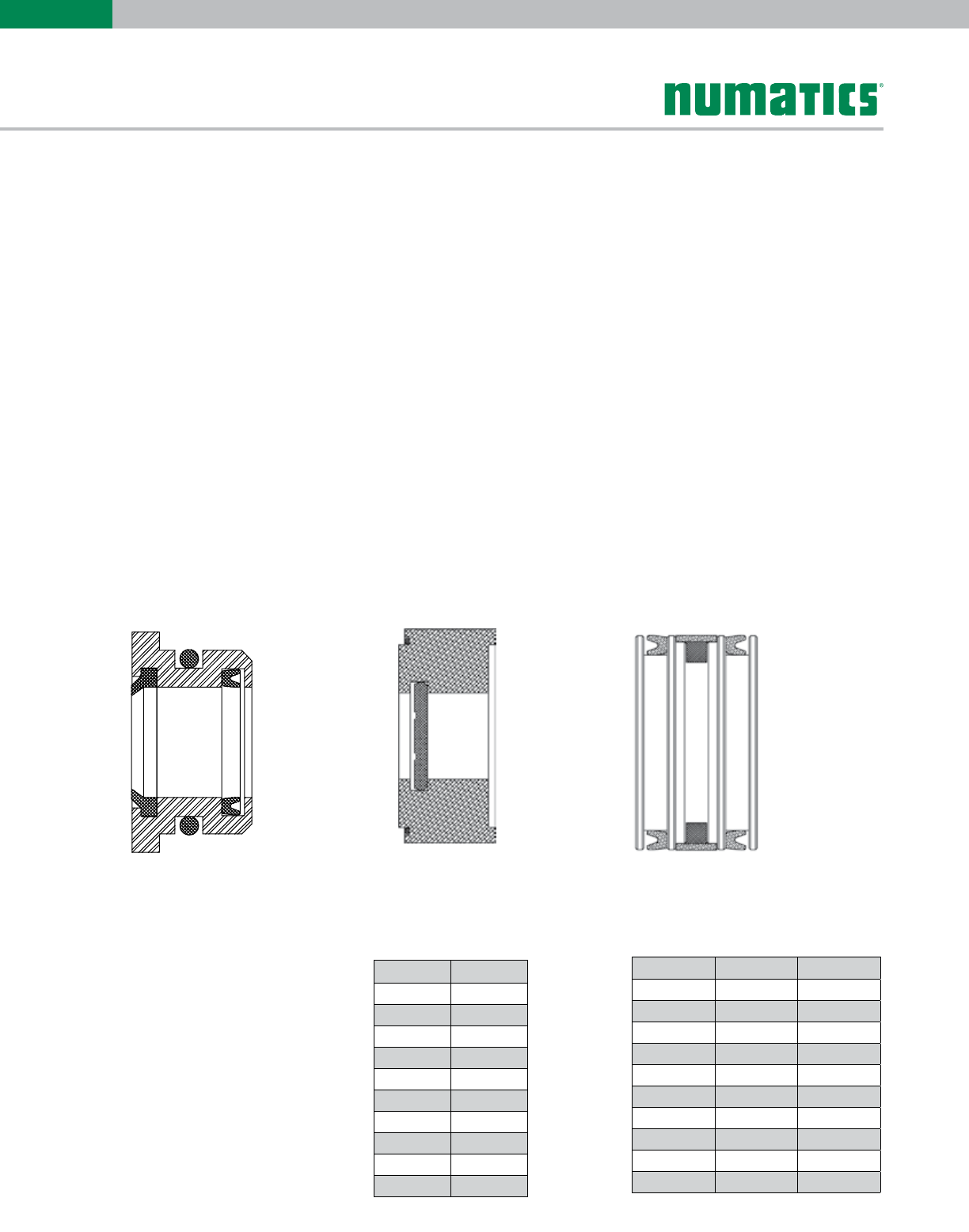
Cushioned Cylinders 1-1/4" through 4-1/2" bore only: Add 1" for each cushion
5", 6" and 8" bore only: No change in length for cushions
Head Cushion Only
Up to 4-1/2" Bore
Cap Cushion Only
Up to 4-1/2" Bore
Head and Cap Cushioned
Up to 4-1/2" Bore
Basic E-Series Dimensions
Bore Rod Dia. E EE G J K LB P R RD Y ZB
1-1/4 0.375 1.813 1/8 1.125 0.750 1/4-28 X 0.38 2.906 2.063 1.281 1.813 1.125 3.531
1-3/4 0.750 2.375 1/4 1.437 1.235 5/16-24 X 0.50 3.797 2.362 1.718 2.375 1.500 4.547
2 0.750 2.375 1/4 1.437 1.235 1/4-28 X 0.38 3.797 2.362 1.875 2.375 1.500 4.547
2-1/2 0.750 2.875 3/8 1.437 1.235 5/16-24 X 0.50 3.797 2.425 2.203 2.875 1.438 4.547
3 0.750 3.375 3/8 1.437 1.235 5/16-24 X 0.50 3.797 2.425 2.625 3.375 1.438 4.547
3-1/2 1.000 4.000 1/2 2.000 1.250 3/8-24 X 0.63 4.545 3.076 3.219 4.125 1.844 5.545
4-1/2 1.000 5.000 1/2 2.000 1.250 1/2-20 X 0.63 4.545 3.076 4.031 5.125 1.844 5.545
5 1.000 5.500 1/2 2.000 1.250 1/2-20 X 0.63 4.797 3.328 4.100 5.500 1.844 5.797
6 1.500 6.500 3/4 2.000 1.500 1/2-20 X 0.63 5.3750 3.750 4.875 6.500 2.125 6.625
8 1.500 8.500 3/4 2.000 1.500 5/8-18 X 0.75 5.750 3.750 6.440 8.500 2.125 6.625
Dimensions: Inches
Information subject to change without notice. For ordering information or regarding your local sales office visit www.numatics.com.
6
E
SERIES
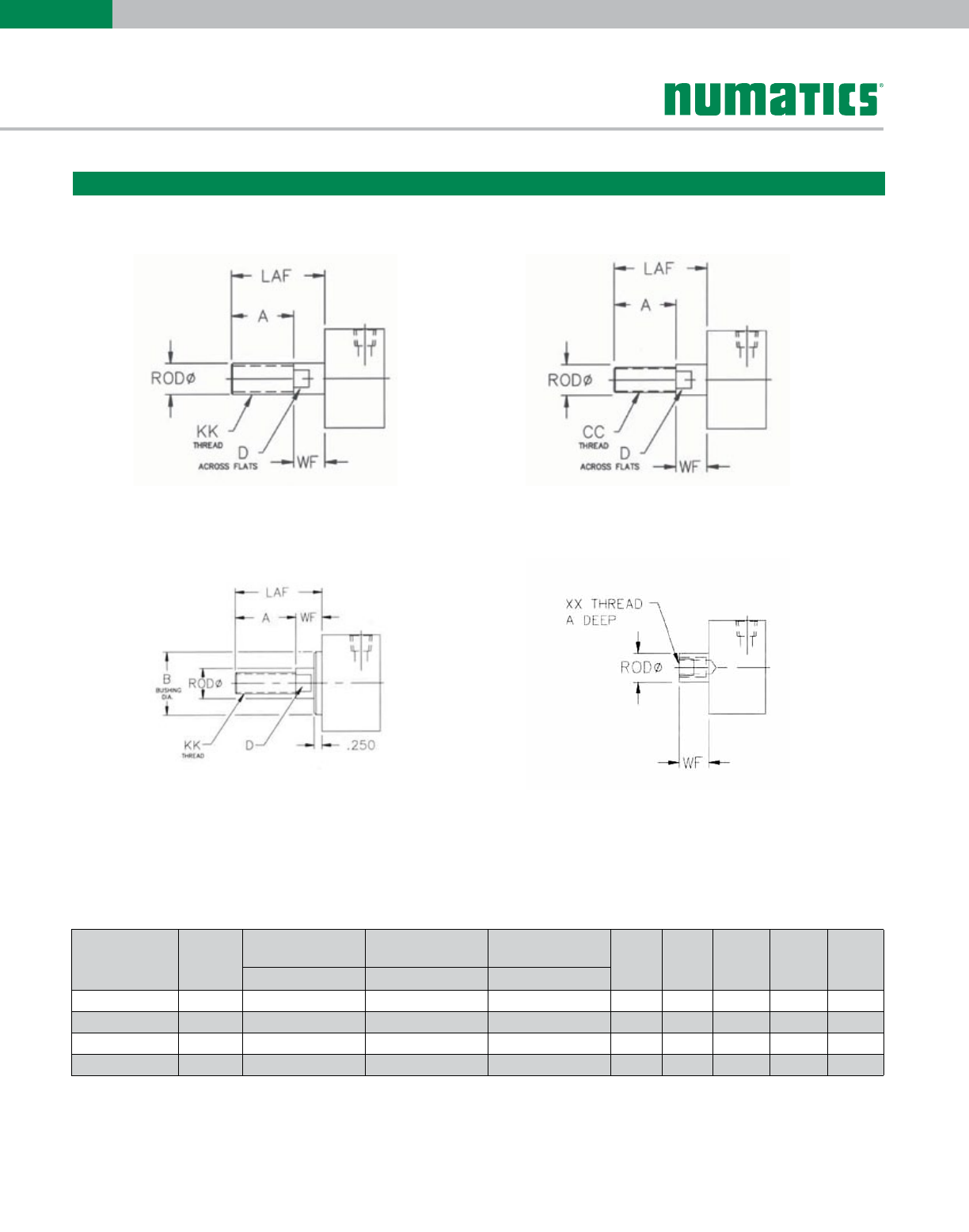
Style 1
1-1/4" Through 5" Bore Only
E-Series Rod Ends
Piston Rod Ends
Style 2
Style 1
6" and 8" Bore Only
Style 3
Bore Rod Dia.
Style #1
(Male Thread)
Style #2
(Male Thread)
Style #3
(Female Thread) A B D LAF WF
KK CC XX
1-1/4 0.375 3/8-16 1/4-20 1/4-20 1.000 N/A 0.312 1.625 0.625
1-3/4, 2, 2-1/2, 3 0.750 3/4-10 1/2-13 1/2-13 1.500 N/A 0.625 2.250 0.750
3-1/2, 4-1/2, 5 1.000 1-8 3/4-10 3/4-10 1.625 N/A 0.875 2.625 1.000
6, 8 1.500 1 1/4-12 1-8 1 1/4-12 1.625 2.00 1.313 2.500 0.875
Dimensions: Inches
Information subject to change without notice. For ordering information or regarding your local sales office visit www.numatics.com.
7
E
SERIES
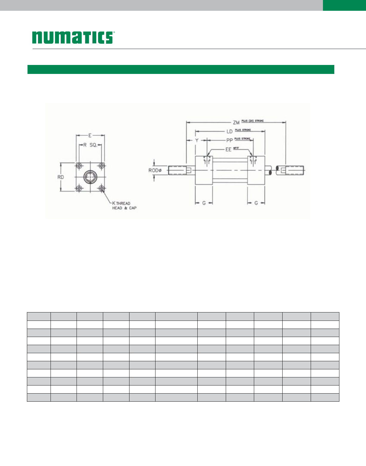
Standard and Optional Rod Ends
Double Rod
Order as "DA" Option
E-Series Double Rod Dimensions
Bore Rod Dia. E EE G K LD PP RD Y ZM
1-1/4 0.375 1.813 1/8 1.125 1/4-28 X 0.38 3.281 2.281 1.813 1.125 4.531
1-3/4 0.750 2.375 1/4 1.437 5/16-24 X 0.50 4.000 2.500 2.375 1.500 5.600
2 0.750 2.375 1/4 1.437 1/4-28 X 0.38 4.000 2.500 2.375 1.500 5.500
2-1/2 0.750 2.875 3/8 1.437 5/16-24 X 0.50 4.000 2.625 2.875 1.438 5.500
3 0.750 3.375 3/8 1.437 5/16-24 X 0.50 4.000 2.625 3.375 1.438 5.500
3-1/2 1.000 4.000 1/2 2.000 3/8-24 X 0.63 5.295 3.607 4.125 1.844 7.295
4-1/2 1.000 5.000 1/2 2.000 1/2-20 X 0.63 5.295 3.607 5.125 1.844 7.296
5 1.000 5.500 1/2 2.000 1/2-20 X 0.63 5.547 3.859 5.500 1.844 7.547
6 1.500 6.500 3/4 2.000 1/2-20 X 0.63 6.250 3.750 6.500 2.125 8.000
8 1.500 8.500 3/4 2.000 5/8-18 X 0.75 6.250 3.750 8.500 2.125 8.000
Dimensions: Inches
Information subject to change without notice. For ordering information or regarding your local sales office visit www.numatics.com.
8
E
SERIES
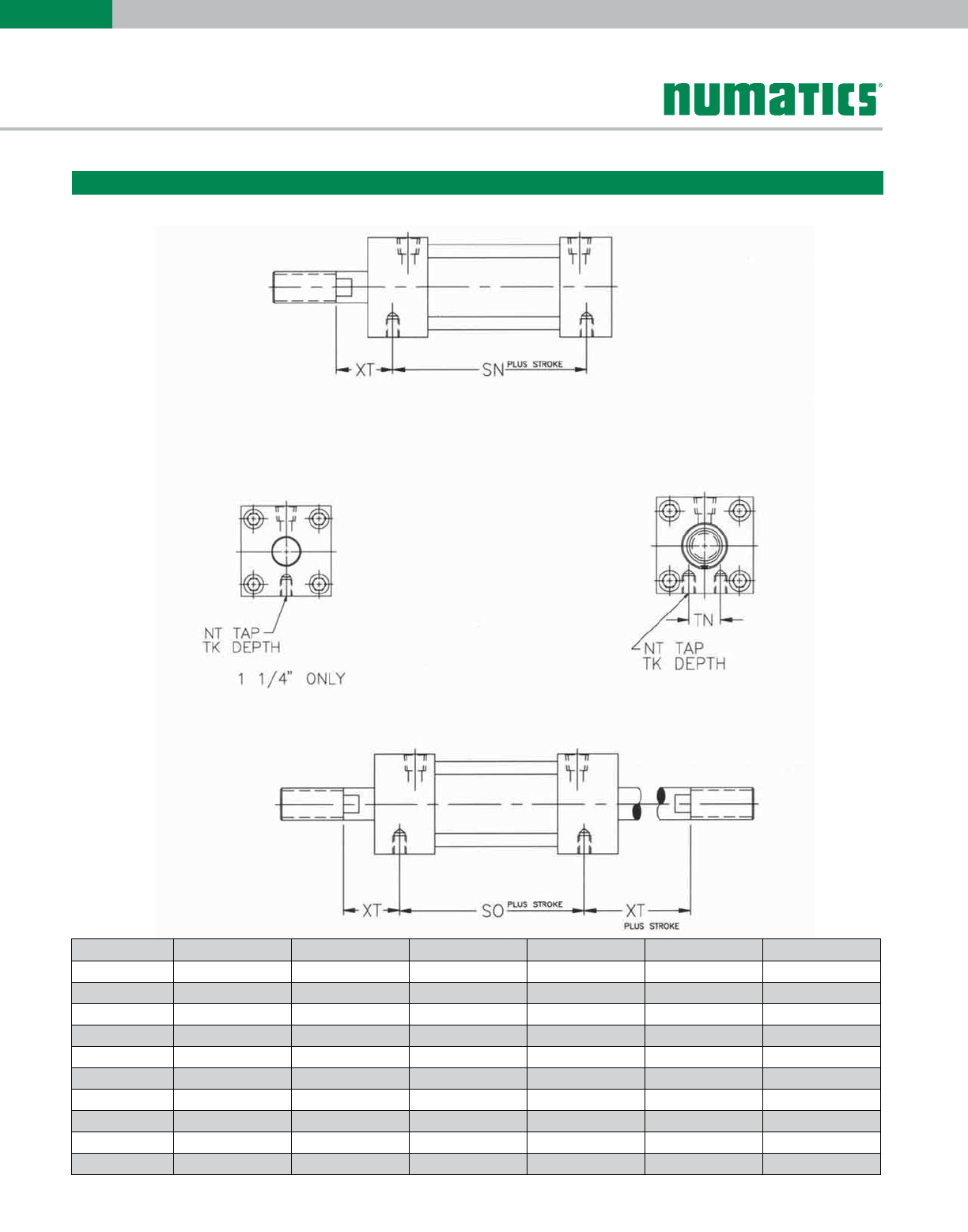
Bore NT TK SN SO TN XT
1-1/4 1/4-28 0.313 2.03 2.41 N/A 1.06
1-3/4 5/16-24 0.438 2.61 2.81 0.78 1.34
2 5/16-24 0.438 2.61 2.81 0.78 1.34
2-1/2 5/16-24 0.563 2.61 2.81 1.25 1.34
3 5/16-24 0.563 2.61 2.81 1.25 1.34
3-1/2 3/4-24 0.688 3.11 3.73 1.84 1.72
4-1/2 1/2-20 0.688 3.11 3.73 2.50 1.72
5 1/2-20 0.688 3.30 4.05 2.69 1.75
6 1/2-20 0.625 3.75 3.75 3.25 2.12
8 5/8-18 0.750 3.75 3.75 4.50 2.12
Bottom Tapped Mount
Dimensions: Inches
Information subject to change without notice. For ordering information or regarding your local sales office visit www.numatics.com.
9
E
SERIES
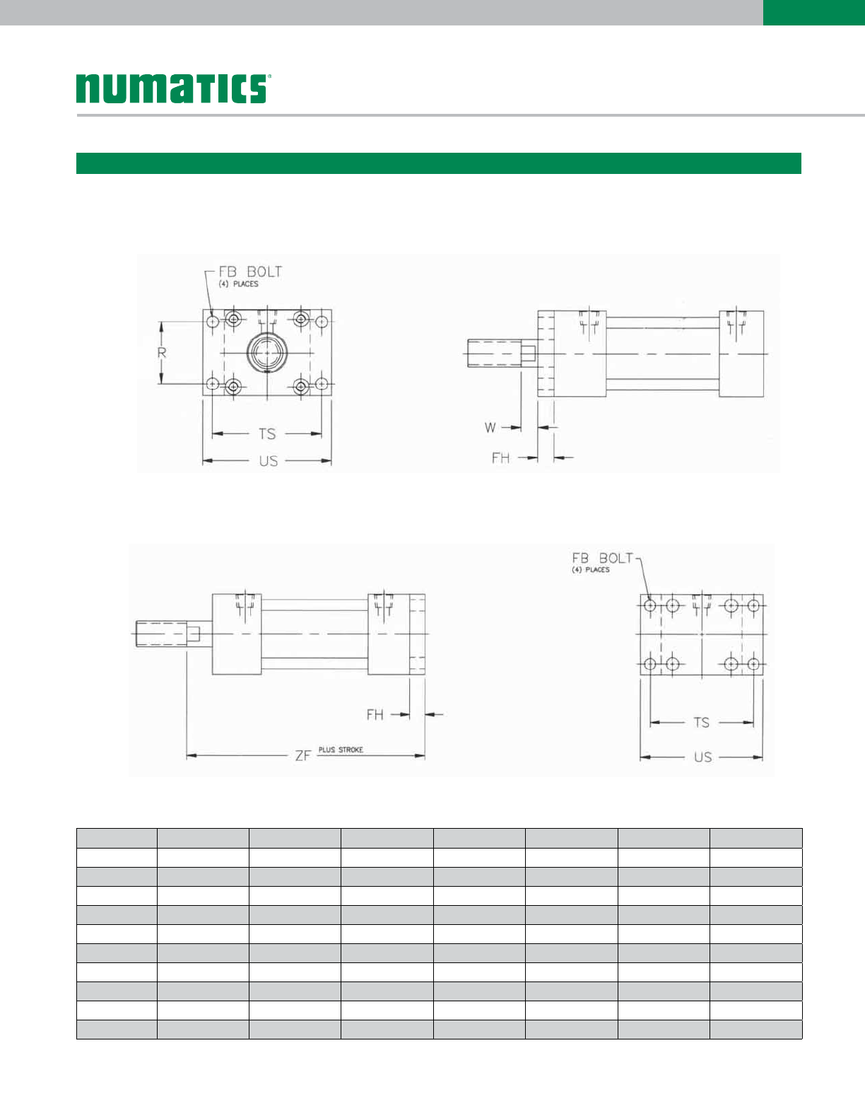
Flange Mounts
Mount Code F1
Mount Code F2
Bore FB FH R TS US W ZF
1-1/4 0.250 0.375 1.281 2.312 2.750 0.250 3.906
1-3/4 0.313 0.438 1.718 3.031 3.594 0.313 4.984
2 0.313 0.438 1.875 3.031 3.625 0.313 4.984
2-1/2 0.313 0.438 2.203 3.437 4.000 0.313 4.984
3 0.313 0.438 2.625 3.875 4.500 0.313 4.984
3-1/2 0.375 0.625 3.219 5.062 5.937 0.375 6.170
4-1/2 0.500 0.625 4.031 6.062 7.000 0.375 6.170
5 0.500 0.625 4.100 6.562 7.500 0.375 6.422
6 0.500 0.750 4.875 7.625 8.500 0.125 7.375
8 0.625 0.875 6.440 10.000 11.250 0 7.500
Dimensions: Inches
Information subject to change without notice. For ordering information or regarding your local sales office visit www.numatics.com.
10
E
SERIES
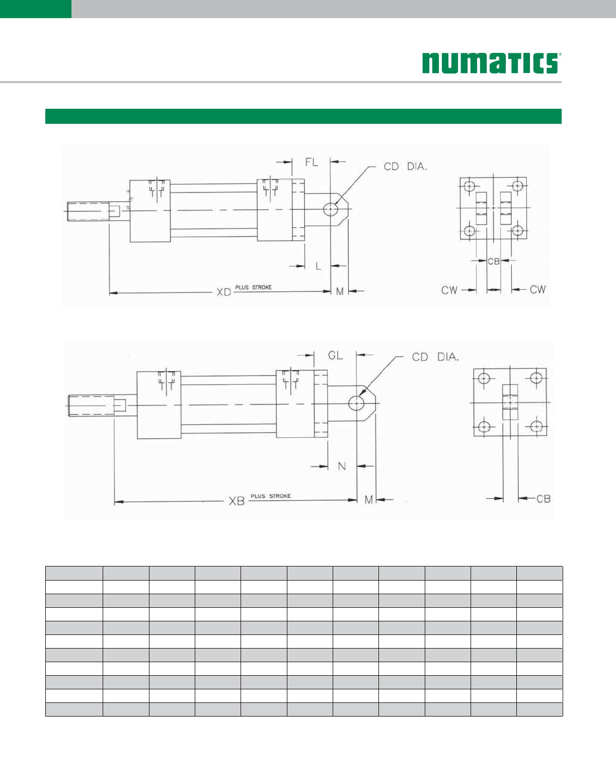
Mount Code P2
Mount Code P4
Clevis and Eye Mounts
Bore L M N CB CD CW FL GL XB XD
1-1/4 0.750 0.438 1.250 0.250 0.375 0.250 1.000 1.500 5.031 4.531
1-3/4 1.000 0.625 1.500 0.500 0.500 0.375 1.375 1.875 6.422 5.922
2 1.000 0.625 1.500 0.500 0.500 0.375 1.375 1.875 6.422 4.922
2-1/2 1.125 0.813 1.750 0.500 0.625 0.375 1.500 2.125 6.675 6.047
3 1.750 0.816 1.750 0.500 0.625 0.375 2.125 2.125 6.675 6.672
3-1/2 1.563 1.000 2.500 0.500 0.750 0.500 2.063 3.000 8.545 7.608
4-1/2 1.875 1.125 3.000 0.500 0.750 0.500 2.375 2.500 9.297 8.172
5 1.875 1.125 3.000 0.500 0.750 0.500 2.375 3.500 9.297 8.172
6 1.625 1.125 1.625 1.500 1.000 0.750 2.250 2.250 8.875 8.875
8 1.625 1.125 1.625 1.500 1.000 0.750 .250 2.250 8.875 8.875
Dimensions: Inches
Information subject to change without notice. For ordering information or regarding your local sales office visit www.numatics.com.
11
E
SERIES
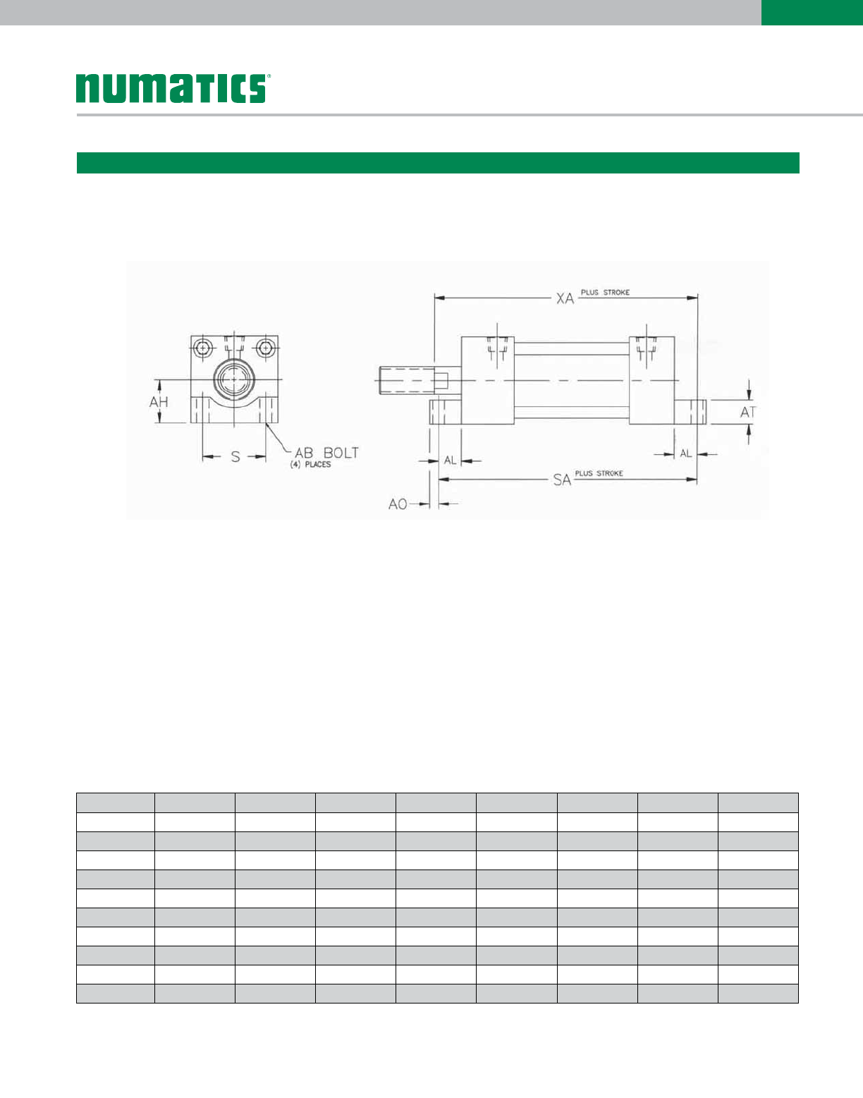
End Lug Mount
Mount Code S7
Bore AB AH AL AO AT S SA XA
1-1/4 1/4 0.906 0.500 0.250 0.625 1.281 3.906 4.031
1-3/4 5/16 1.188 0.625 0.250 0.875 1.781 5.047 5.173
2 1/4 1.188 0.500 0.250 0.625 1.875 4.797 5.048
2-1/2 5/16 1.438 0.625 0.250 0.875 2.203 5.047 5.173
3 5/16 1.688 0.625 0.250 0.875 2.625 5.047 5.173
3-1/2 1/2 2.063 1.000 0.375 1.375 3.219 6.545 6.546
4-1/2 1/2 2.563 1.000 0.375 1.375 4.031 6.545 6.545
5 1/2 2.750 1.000 0.375 1.375 4.100 6.797 6.797
6 1/2 3.250 1.000 0.375 1.375 4.875 7.750 7.625
8 1/2 4.250 1.250 0.750 2.000 6.440 8.250 7.875
Dimensions: Inches
Information subject to change without notice. For ordering information or regarding your local sales office visit www.numatics.com.
12
E
SERIES
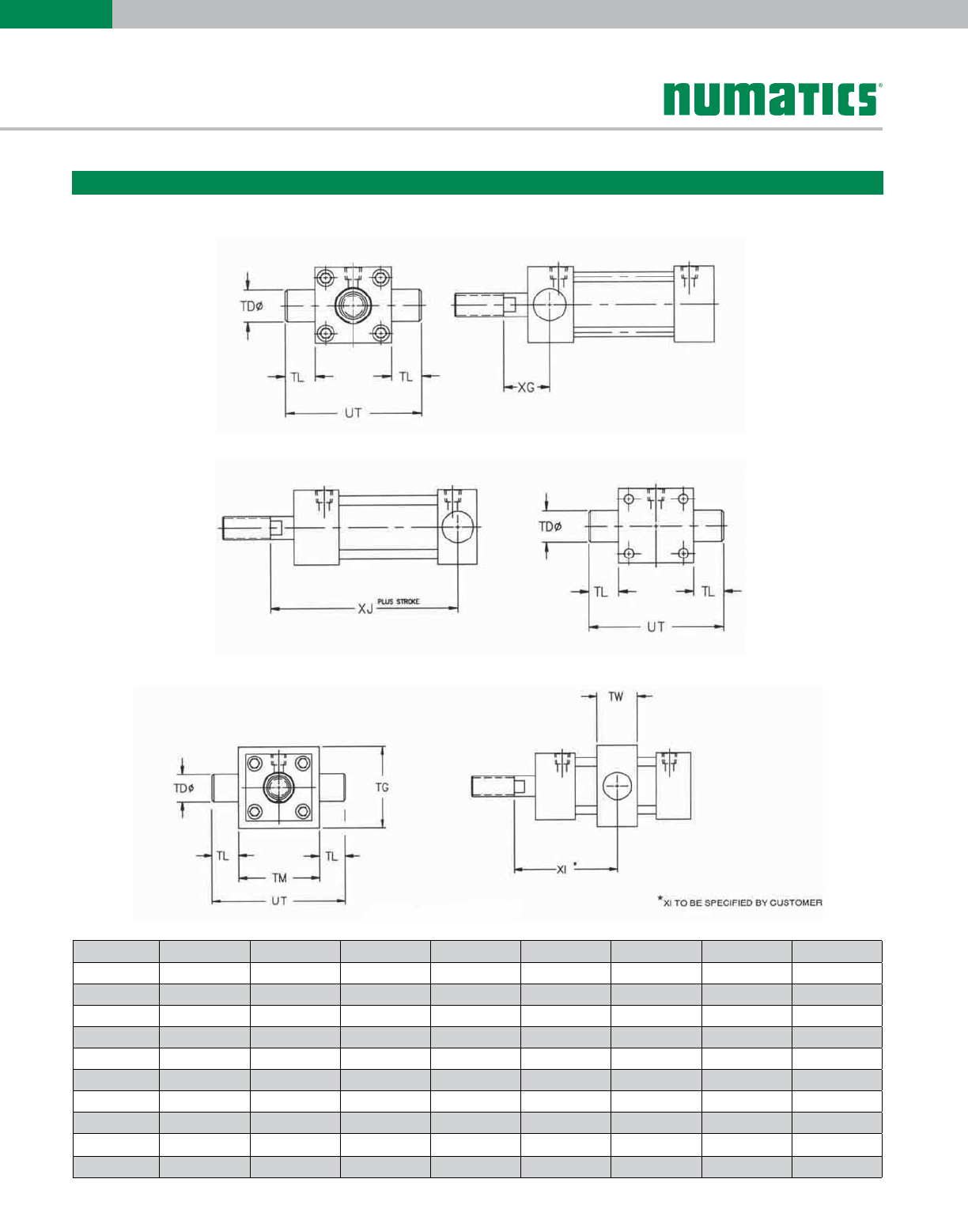
Trunnion Mounts
Mount Code T2
Mount Code T2
Mount Code T1
Bore TD TG TL TM TW UT XG XJ
1-1/4 0.375 2.375 0.438 2.375 1.250 2.688 1.156 3.188
1-3/4 1.000 2.875 0.938 2.875 1.438 4.250 1.438 3.959
2 1.000 2.875 0.938 2.875 1.438 4.250 1.438 3.959
2-1/2 1.000 3.375 0.938 3.375 1.438 4.750 1.438 3.959
3 1.000 4.125 0.938 4.000 1.438 5.250 1.438 3.959
3-1/2 1.000 5.125 0.938 5.000 2.000 5.875 1.953 4.967
4-1/2 1.000 5.500 0.938 5.500 2.000 6.875 1.953 4.967
5 1.000 6.500 0.938 6.500 2.000 7.375 1.953 5.219
6 1.375 8.500 1.375 8.500 2.000 9.250 1.830 5.922
8 1.375 N/A 1.375 N/A N/A 11.250 1.830 5.922
Dimensions: Inches
Information subject to change without notice. For ordering information or regarding your local sales office visit www.numatics.com.
13
E
SERIES
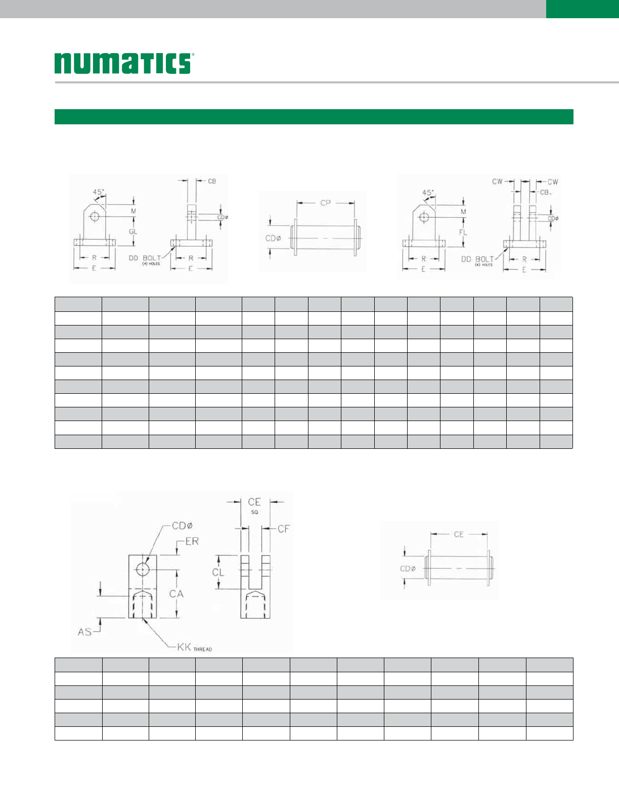
Accessories
Detachable Eye Pivot Pin for Detachable Clevis Detachable Clevis
Bore Clevis PIN Eye CB CD CP CW DD E FL GL M R
1-1/4 E500-001 E500-401 E500-101 0.250 0.375 0.750 0.250 1/4 1.813 1.000 1.500 0.438 1.281
1-3/4 E500-002 E500-402 E500-102 0.500 0.500 1.250 0.375 5/16 2.375 1.375 1.875 0.625 1.718
2 E500-003 E500-402 E500-103 0.500 0.500 1.250 0.375 5/16 2.375 1.375 1.875 0.625 1.875
2-1/2 E500-304 E500-403 E500-104 0.500 0.625 1.250 0.375 5/16 2.875 1.500 2.125 0.813 2.203
3 E500-305 E500-403 E500-105 0.500 0.625 1.250 0.375 5/16 3.375 2.125 2.125 0.813 4.625
3-1/2 E500-006 E500-404 E500-106 0.500 0.750 1.500 0.500 3/8 4.000 2.063 3.000 1.000 3.219
4-1/2 E500-007 E500-404 E500-107 0.500 0.750 1.500 0.500 1/2 5.000 2.375 3.500 1.125 4.031
5 E500-008 E500-404 E500-108 0.500 0.750 1.500 0.500 1/2 5.500 2.375 3.500 1.125 4.100
6 E500-009 E500-405 E500-109 1.500 1.000 3.000 0.750 1/2 6.500 2.250 2.250 1.125 4.875
8 E500-010 E500-405 E500-110 1.500 1.000 3.000 0.750 5/8 8.500 2.250 2.250 1.125 6.440
Rod Clevis Pivot Pin for Rod Clevis
Bore Clevis PIN AS CA CD CE CF CL ER KK
1-1/4 E500-301 E500-401 0.875 1.344 0.375 0.750 0.250 0.906 0.375 3/8-16
1-3/4, 2 E500-302 E500-406 1.000 1.875 0.500 1.125 0.500 1.313 0.563 3/4-10
2-1/2, 3 E500-303 E500-407 1.000 2.063 0.625 1.125 0.500 1.500 0.563 3/4-10
2-1/2 E500-304 E500-404 1.000 2.313 0.750 1.500 0.500 1.875 0.750 1-8
3 E500-305 E500-408 1.625 3.000 1.000 2.000 1.000 2.000 1.000 1 1/4-12
Dimensions: Inches
Information subject to change without notice. For ordering information or regarding your local sales office visit www.numatics.com.
14
E
SERIES
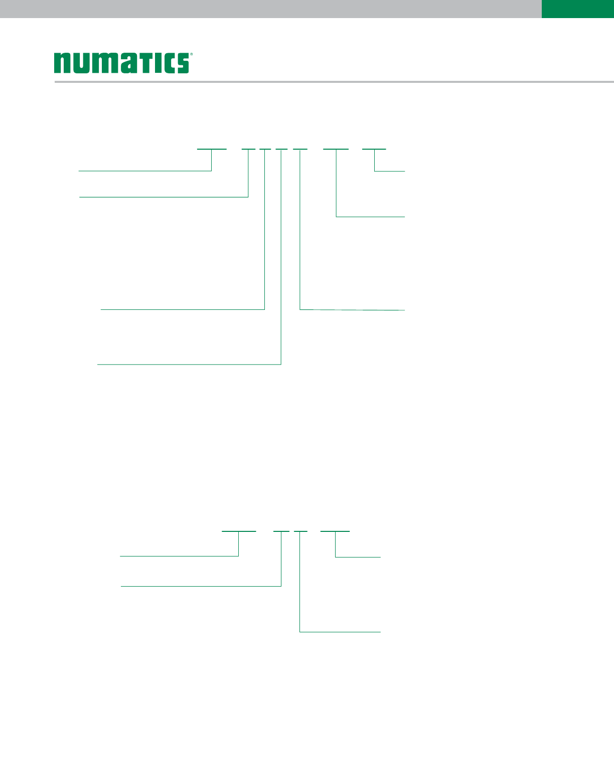
How to Order - E Series Piston Rod Assembly
Type
E92 =E Series Piston Rod Assembly
Bore
F= 1-1/4"
I = 1 3/4"
L = 2"
M = 2-1/2"
N = 3"
Q = 3-1/2"
S = 4-1/2"
T = 5"
U = 6"
W = 8"
Rod Code
1 = Style #1 Standard Rod Diameter
2 = Style #2 Standard Rod Diameter
3 = Style #3 Standard Rod Diameter
4= Special Threads, Standard Rod Diameter
(must specify threads)
Cushion
N = No Cushion
B = Both Ends Cushioned
H = Head End Cushioned
C = Cap End Cushioned
Magnet
0 = No Magnet
2 = Reed Magnet
N0 AA
Option
AA = No Option
BC = Bumpered Cap End
BH = Bumpered Head End
DA = Double Rod
JN = Jam Nut
KA = Stroke Adjust
NA = Nickel Plated
SA = Stainless Rod
VA = FKM Seals
1A* = Rod Extension
1B* = Rear Rod Extension
2A* = Thread Extension
2B* = Rear Thr
ead Extension
3A = Rod Stud
3B = Rear Rod Stud
4A* = Stop Tube
* Must specify length
Fractional Inches of Stroke
A0"I1/2"
B 1/16" J 9/16"
C 1/8" K 5/8"
D 3/16" L 11/16"
E 1/4" M 3/4"
F 5/16" N 13/16"
G 3/8" O 7/8"
H
=
=
=
=
=
=
=
= 7/16" P
=
=
=
=
=
=
=
= 15/16"
Full Inch of Stroke
00 = 0" Stroke
01 = 1" Stroke
02 = 2" Stroke
03 = 3" Stroke
04 = 4" Stroke
99 = 99" Stroke
E92 ---01F1 A
Note: Options listed are ones that apply to a piston rod assembly only.
Model number is set up to use option code supplied with original cylinder or with any above.
Bore Rod Dia. Style #1
(Male Thread)
Style #2
(Male Thread)
Style #3
(Female Thread)
1-1/4" 0.375 3/8-16 1/4-20 1/4-20
1-3/4", 2", 2-1/2", 3" 0.750 3/4-10 1/2-13 1/2-13
3-1/2", 4-1/2", 5" 1.000 1-8 3/4-10 3/4-10
6", 8" 1.500 1 1/4-12 1-8 1 1/4-12
Rod End Styles, Diameters and Threads
Information subject to change without notice. For ordering information or regarding your local sales office visit www.numatics.com.
15
E
SERIES
How to Order - E Series Repair Kit
Type
E98 = E Series Repair Kit
Bore
F = 1-1/4"
I = 1-3/4"
L = 2"
M = 2-1/2"
N = 3"
Q = 3-1/2"
S = 4-1/2"
T = 5"
U = 6"
W = 8"
Cushion
N = No Cushion
B = Both Ends Cushioned
H = Head End Cushioned
C = Cap End Cushioned
Mount
0* = All bores except 1-1/4"
1-1/4" bore only
1 = S4 & P7
2 = T1
3 = F1, F2, P2, P4,S7, T2, T4, X0
* 1-1/4" bore has pressed in bushing.
1B B
Port Modifications (Only on 1-1/4" Bore)rt
B = Port Modified
Note: Leave Blank if
No Port Modifications
Option
AA = No Option
BC = Bumpered Cap End
BH = Bumpered Head End
DA = Double Rod
MA = Metallic Rod Scraper
MB = Rear Metallic Rod Scraper
NA = Nickel Plated
VA = FKM Seals
* Port
All Bores Except 1-1/4"
1-1/4" bore only
B = 1/8" Port Position 1
H = 1/8" Port Position 2
N = 1/8" Port Position 3
T = 1/8" Port Position 4
C = 1/4" Port Position 1
I = 1/4" Port Position 2
O = 1/4" Port Position 3
U = 1/4" Port Position 4
E98 ---AAFN
Note: Options listed are ones that apply to a repair kit only.
Model number is set up to use option code supplied with original cylinder or with any above.
How to Order - E Series Seal Kit
Type
Bore
Option
AA = No Option
DA = Double Rod
MA = Metallic Rod Scraper
MB = Rear Metallic Rod Scraper
VA = FKM Seals
Cushion
N = No Cushion
B = Both Ends Cushioned
H = Head End Cushioned
C = Cap End Cushioned
E97 -AA-FN
E97 = E Series Seal Kit
F = 1-1/4"
I = 1-3/4"
L = 2"
M = 2-1/2"
N = 3"
Q = 3-1/2"
S = 4-1/2"
T = 5"
U = 6"
W = 8"
Note: Options listed are ones that apply to a seal kit only.
Model number is set up to use option code supplied with original cylinder or with any above.
Information subject to change without notice. For ordering information or regarding your local sales office visit www.numatics.com.
16
E
SERIES
Piston Rod Assembly Removal/Installation Instructions
1. Loosen 4 Sleeve Nuts (Part #8) to remove Piston/Rod Assembly (Part #16 & #19)
2. Carefully remove old seals. (Part #13 & #15) Any damage to the seal grooves may result in leakage.
3. Lubricate piston seals (Part #13) and wearband (Part #15) with supplied Numatics’ Lube. Examine seals before installing for
any contamination. Contamination may cause leakage.
4. Install Piston Seal (Part #13). Make sure the piston seal is not twisted inside groove. See Seal Installation Guide.
5. Install lubricated Wearband (Part #15) onto piston. Sink piston/rod assembly into sinker tube.
6. Apply lube inside the cylinder tube.
7. Sink piston/rod assembly into cylinder tube.
8. Press piston/rod assembly flush with the cylinder tube. Wipe off any lube from the face of the piston.
9. Examine seals after installing for any contamination. Contamination may cause leakage.
10. Lightly grease Rod Seal (Part #3) and Bushing O-ring (Part #2). This will ease the installation of the rod bushing over the rod
and into the head.
11. Reassemble cylinder. Loosely torque Sleeve Nuts to allow head and cap to rotate slightly.
12. Before final torque, place cylinder on level surface to square head and cap. Torque Sleeve Nuts in a crisscross pattern. Use
the following charts for torque tolerances for Sleeve Nuts.
13. Stroke cylinder by hand. This will enable detection of any binding. If binding does occur, repeat steps 11-13.
Tie Rod Torque Tolerances
(lbs-ft) Part #8
Bore Min. Max.
1-1/4" 8 10
1-3/4" 8 10
2" 8 10
2-1/2" 15 18
3" 15 18
3-1/2" 23 30
4-1/2" 50 60
5" 50 60
6" 50 60
8" 80 90
Sinker Tube Part
Numbers
Bore Part #
1-1/4" E06-F91
1-3/4" E06-I91
2" A06-L91
2-1/2" A06-M91
3" C06-N91
3-1/2" E06-Q91
4-1/2" E06-S01
5" A06-T91
6" A06-U91
8" A06-W91
Note: Sinker Tubes are not included
in kits. They can be ordered using
the part numbers from the provided
chart.
Loaded Bushing
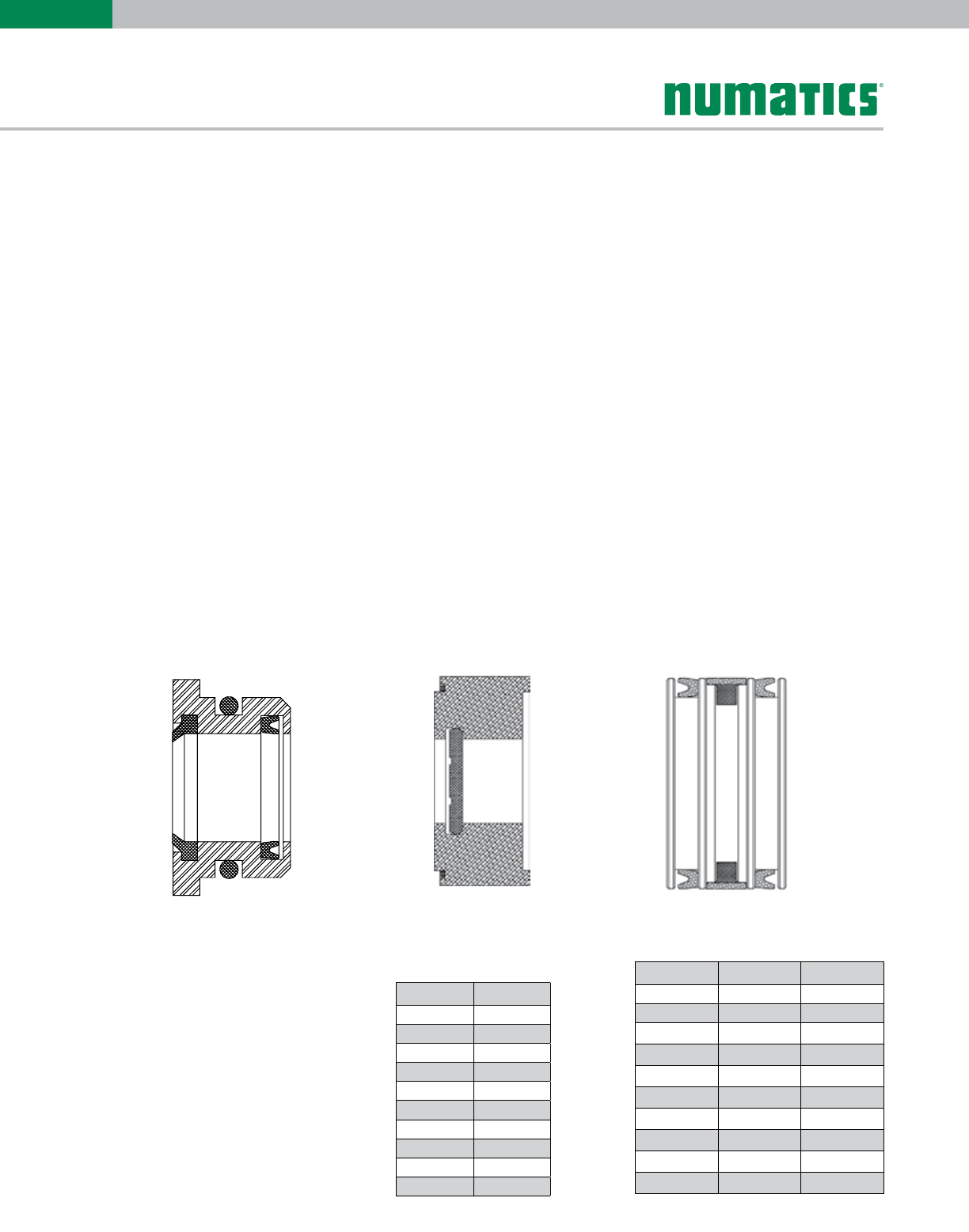
Seal Installation Guide
Head or Cap Cushion Block Piston
Information subject to change without notice. For ordering information or regarding your local sales office visit www.numatics.com.
17
E
SERIES
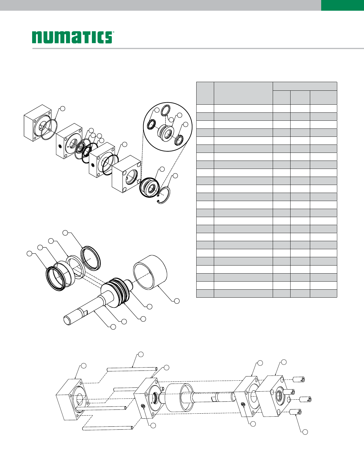
E Series
Part # Description
Parts included in:
Seal
Kit
Repair
Kit
Piston/Rod
Assembly
1 Rod Wiper X
2 Bushing O-ring X
3 Rod Seal X
4 Bushing
5 Loaded Bushing Assembly X
6 Cap
7 Cushion Needle
8 Sleeve Nuts
9 Tube End Seals X X
10 Bushing Snap Ring
11 Head
12 Head Cushion Seal X X
13 Piston Seals X X
14 Magnet X
15 Wearband X X
16 Rod X
17 Head Cushion Spear X
18 Cap Cushion Spear X
19 Piston X
20 Tube
21 Tie Rods
22 Head Cushion Block
23 Cap Cushion Block
24 Cap Cushion Seal X X
2
3
9
24
912
9
9
5
10
4
1
6
21
23
22 11
77
8
Head, Cap, and Bushing Assembly
Piston/Rod Assembly
13
15
14
13
16
17
19
18
20
Cylinder Assembly and Tie Rod Torque
Diagrams
Pneumatic Service Temperatures:
Nitrile Seals: -10˚F (-23˚C) to 165˚F (74˚C)
FKM Seals: 0˚F (-17˚C) to 400˚F (204˚C)
Information subject to change without notice. For ordering information or regarding your local sales office visit www.numatics.com.
18
E
SERIES
Repair Kit Removal/Installation Instructions
1. Remove Snap Ring (Part #10) to remove old Loaded Bushing (Part # 5)
2. Loosen 4 Sleeve Nuts (Part #8) to remove Piston/Rod Assembly (Part #16 & #19)
3. Carefully remove old seals. (Part #9, #12*, #13, #15, & #24) Any damage to the seal grooves may result in leakage.
4. Lubricate new seals with supplied Numatics’ Lube. Examine seals before installing for any contamination. Contamination
may cause leakage.
5. Install Piston Seal (Part #13). Make sure the piston seal is not twisted inside groove. See Seal Installation Guide.
6. Install lubricated Wearband (Part #15) onto piston. Sink piston/rod assembly into sinker tube.
7. Apply lube inside the cylinder tube.
8. Sink piston/rod assembly into cylinder tube.
9. Press piston/rod assembly flush with the cylinder tube. Wipe off any lube from the face of the piston.
10. Place Tube End Seals (Part #9) into head and cap seal grooves. If cylinder is cushioned, the kit will have additional tube end
seals for the cushion block tube end seal grooves. Examine seals after installing for any contamination. Contamination may
cause leakage.
11. Lightly grease Rod Seal (Part #3) and Bushing O-ring (Part #2) on the supplied loaded bushing. This will ease the
installation of the rod bushing over the rod and into the head.
12. Reassemble cylinder except for loaded bushing. First, loosely torque Sleeve Nuts to allow head and cap to rotate slightly.
Carefully place bushing over the rod until getting interference. With a twisting motion, slide the bushing down onto the rod and
into the bushing pocket on the head.
13. Make sure loaded bushing is pressed below snap ring groove. Replace snap ring into the groove. Visually check to see if
snap ring is fully seated in the groove.
14. Before final torque, place cylinder on level surface to square head and cap. Torque Sleeve Nuts in a crisscross pattern. Use
the following charts for torque tolerances for Sleeve Nuts.
15. Stroke cylinder by hand. This will enable detection of any binding. If binding does occur, repeat steps 12-15.
Tie Rod Torque Tolerances
(lbs-ft) Part #8
Bore Min. Max.
1-1/4" 8 10
1-3/4" 8 10
2" 8 10
2-1/2" 15 18
3" 15 18
3-1/2" 23 30
4-1/2" 50 60
5" 50 60
6" 50 60
8" 80 90
Note: Sinker Tubes are not included
in kits. They can be ordered using
the part numbers from the provided
chart.
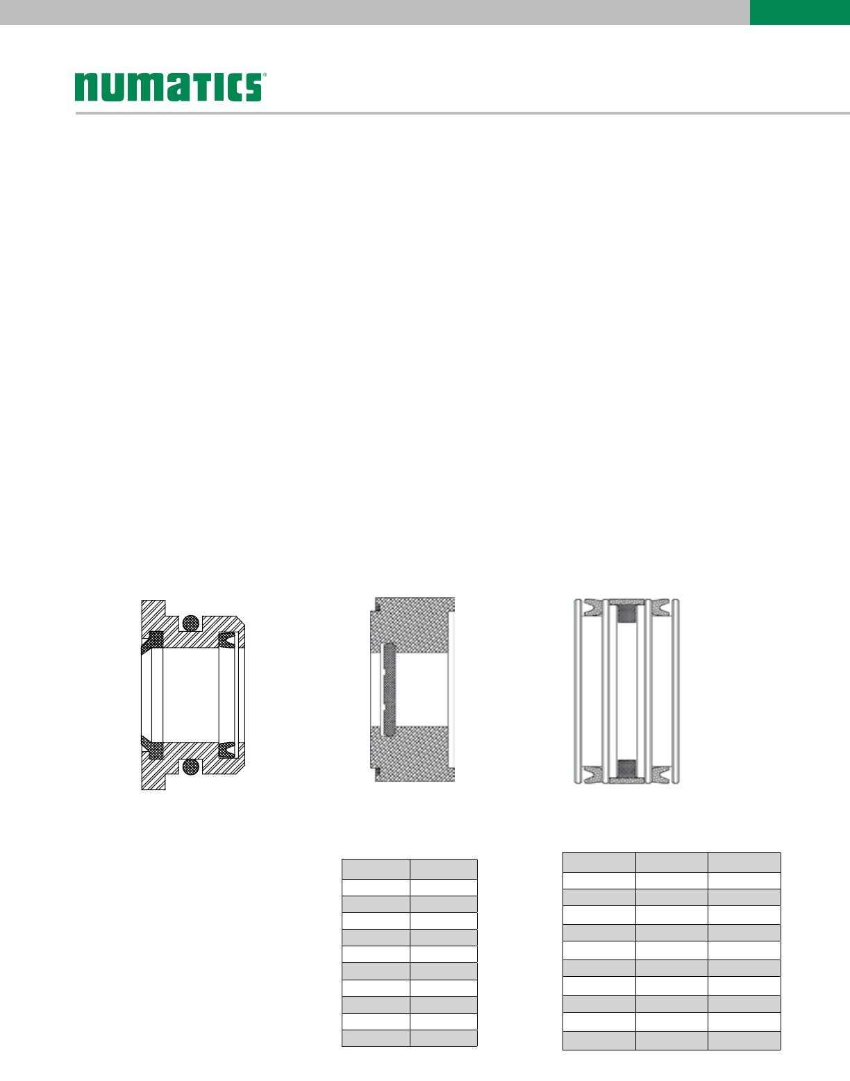
Loaded Bushing
Seal Installation Guide
Head or Cap Cushion Block Piston
Sinker Tube Part
Numbers
Bore Part #
1-1/4" E06-F91
1-3/4" E06-I91
2" A06-L91
2-1/2" A06-M91
3" C06-N91
3-1/2" E06-Q91
4-1/2" E06-S01
5" A06-T91
6" A06-U91
8" A06-W91
Information subject to change without notice. For ordering information or regarding your local sales office visit www.numatics.com.
19
E
SERIES
Seal Kit Removal/Installation Instructions
1. Remove Snap Ring (Part #10) to remove Loaded Bushing (Part # 5)
2. Loosen 4 Sleeve Nuts (Part #8) to remove Piston/Rod Assembly (Part #16 & #19)
3. Carefully remove old seals. (Part #1, #2, #3, #9, #12, #13, #15, & #24) Any damage to the seal grooves may result in
leakage.
4. Lubricate new seals with supplied Numatics’ Lube. Examine seals before installing for any contamination. Contamination may
cause leakage.
5. Install Piston Seal (Part #13). Make sure the piston seal is not twisted inside groove. See Seal Installation Guide.
6. Install lubricated Wearband (Part #15) onto piston. Sink piston/rod assembly into sinker tube.
7. Apply lube inside the cylinder tube.
8. Sink piston/rod assembly into cylinder tube.
9. Press piston/rod assembly flush with the cylinder tube. Wipe off any lube from the face of the piston.
10. Place Tube End Seals (Part #9) into head and cap seal grooves. If cylinder is cushioned, the kit will have additional tube end
seals for the cushion block tube end seal grooves. Examine seals after installing for any contamination. Contamination may cause
leakage.
11. Install Rod Wiper (Part #1), Bushing O-ring (Part #2), and Rod Seal (Part #3) into bushing. Lightly grease Rod Seal and
Bushing O-ring after installation. This will ease the installation of the rod bushing over the rod and into the head.
12. Reassemble cylinder except for loaded bushing. First, loosely torque Sleeve Nuts to allow head and cap to rotate slightly.
Carefully place bushing over the rod until getting interference. With a twisting motion, slide the bushing down onto the rod and into
the bushing pocket on the head.
13. Make sure loaded bushing is pressed below snap ring groove. Replace snap ring into the groove. Visually check to see if
snap ring is fully seated in the groove.
14. Before final torque, place cylinder on level surface to square head and cap. Torque Sleeve Nuts in a crisscross pattern. Use
the following charts for torque tolerances for Sleeve Nuts.
15. Stroke cylinder by hand. This will enable detection of any binding. If binding does occur, repeat steps 12-15.
Note: Sinker Tubes are not included
in kits. They can be ordered using
the part numbers from the provided
chart.
Loaded Bushing
Seal Installation Guide
Head or Cap Cushion Block Piston
Torque Tolerances (lbs-ft)
Part #8
Bore Min. Max.
1-1/4" 8 10
1-3/4" 8 10
2" 8 10
2-1/2" 15 18
3" 15 18
3-1/2" 23 30
4-1/2" 50 60
5" 50 60
6" 50 60
8" 80 90
Sinker Tube Part
Numbers
Bore Part #
1-1/4" E06-F91
1-3/4" E06-I91
2" A06-L91
2-1/2" A06-M91
3" C06-N91
3-1/2" E06-Q91
4-1/2" E06-S01
5" A06-T91
6" A06-U91
8" A06-W91
Information subject to change without notice. For ordering information or regarding your local sales office visit www.numatics.com.
20
E
SERIES
E Series World Switch Bracket
Cylinders Bore Part Number
E series Tie Rod 1 1/4”-2” Bore SB6-K01
E series Tie Rod 1 3/4”-3” Bore SB6-L01
E series Tie Rod 3 1/2”-4” Bore SB6-P01
E series Tie Rod 4 1/2”-6” SB6-T01
E series Tie Rod 8” Bore SB6-W01
1
2
3
4
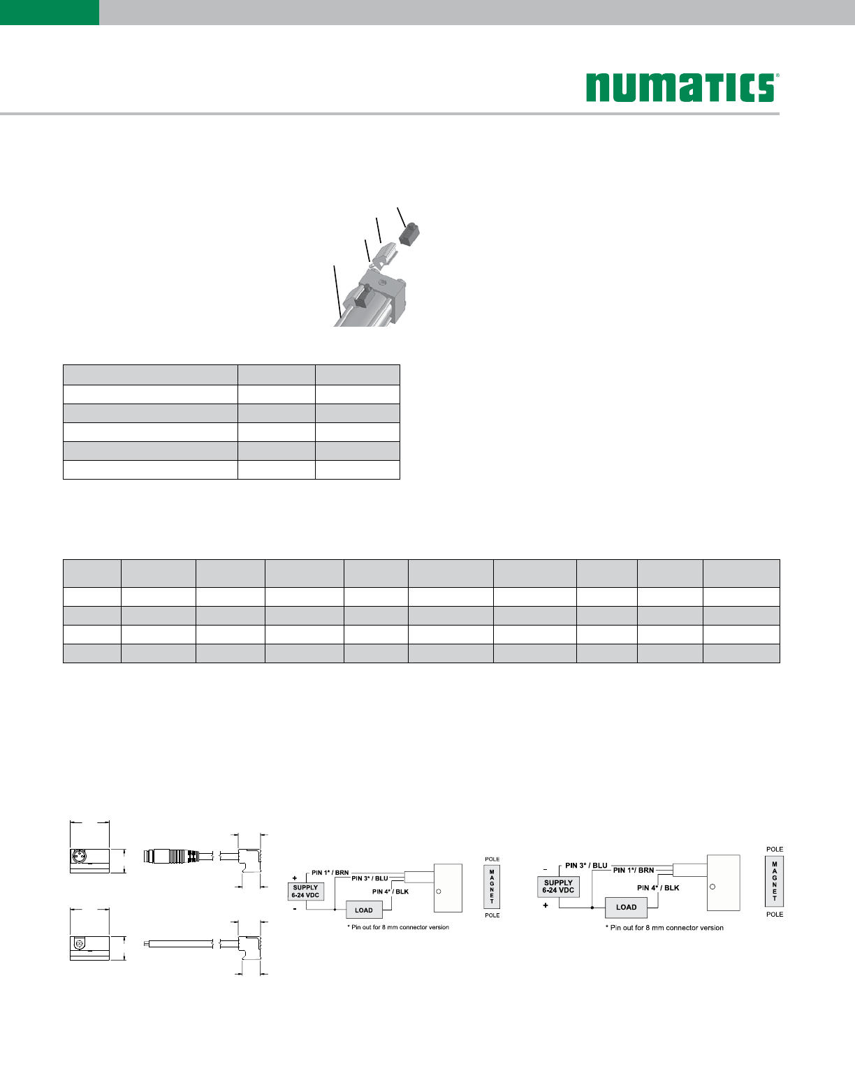
E series World Switch application Detail
Round Tube and Tie Rod Detail
1. World Switch
2. Tie Rod Bracket
3. Adjustment Screw
4. Cylinder Tie Rod
.921
.559
.531
.433
.921
.559
.531
.433
Hall Effect Switch
PNP Sourcing NPN Sinking
P/N Switch Style Electrical
Design Output Operating
Voltage Current Rating Switching
Power
Voltage
Drop
NEMA IP
Rating
Temperature
Rating
SH6-031 Flying Lead DC PNP Normally Open 6-24 VDC 0.3 Amps Max. 7.2 Watts Max. .5 Volts NEMA 6 -25º to +75º C
SH6-032 Flying Lead DC PNP Normally Open 6-24 VDC 0.3 Amps Max. 7.2 Watts Max. .5 Volts NEMA 6 -25º to +75º C
SH6-021 M8 Connector DC NPN Normally Open 6-24 VDC 0.3 Amps Max. 7.2 Watts Max. .5 Volts NEMA 6 -25º to +75º C
SH6-022 M8 Connector DC NPN Normally Open 6-24 VDC 0.3 Amps Max. 7.2 Watts Max. .5 Volts NEMA 6 -25º to +75º C
E Series World Switch Hall Effect Part Numbers
Information subject to change without notice. For ordering information or regarding your local sales office visit www.numatics.com.
21
E
SERIES
.921
.559
.531
.433
.921
.559
.531
.433
Reed Switch - Normally Open Type SR6
Specialty Cylinders
P/N Switch Style Electrical
Design Output Operating
Voltage Current Rating Switching
Power
Voltage
Drop
NEMA IP
Rating
Temperature
Rating
SR6-002 Flying Lead AC/DC REED Normally Open 5-120 VAC/DC 0.025 Amps Max.
0.001 Amps Min. 3 Watts Max. 3.5 Volts NEMA 6 -25º to +75º C
SR6-004 Flying Lead AC/DC REED Normally Open 5-120 VAC/DC 0.5 Amps Max.
0.005 Amps Min. 10 Watts Max. 3.0 Volts NEMA 6 -25º to +75º C
SR6-022 M8 Connector AC/DC REED Normally Open 5-50 VAC
5-60 VDC
0.025 Amps Max.
0.001 Amps Min. 3 Watts Max. .5 Volts NEMA 6 -25º to +75º C
SR6-024 M8 Connector AC/DC REED Normally Open 5-50 VAC
5-60 VDC
0.5 Amps Max.
0.005 Amps Min. 10 Watts Max. 3.0 Volts NEMA 6 -25º to +75º C
E Series World Switch Reed Switch Part Numbers
Sensor
Description
Standard Cord
Set Quick Disconnect
Reed Switch REED-FL2-00 REED-QDS-M8U
Hall PNP PNP-FL2-00-U PNP-QDS-M8-U
Hall NPN NPN-FL2-00-U NPN-QDS-M8-U
E Series (Tie Rod)
Bore Bracket P/N
1 1/4" N99-1181
1 3/4" N99-1182
2" N99-1181
2 1/2" N99-1182
3" N99-1182
3 1/2" N99-1183
4 1/2" N99-1184
5" N99-1184
6" N99-1184
8" N99-1184
See page 22, 23, & 24 for sensor specifications
Information subject to change without notice. For ordering information or regarding your local sales office visit www.numatics.com.
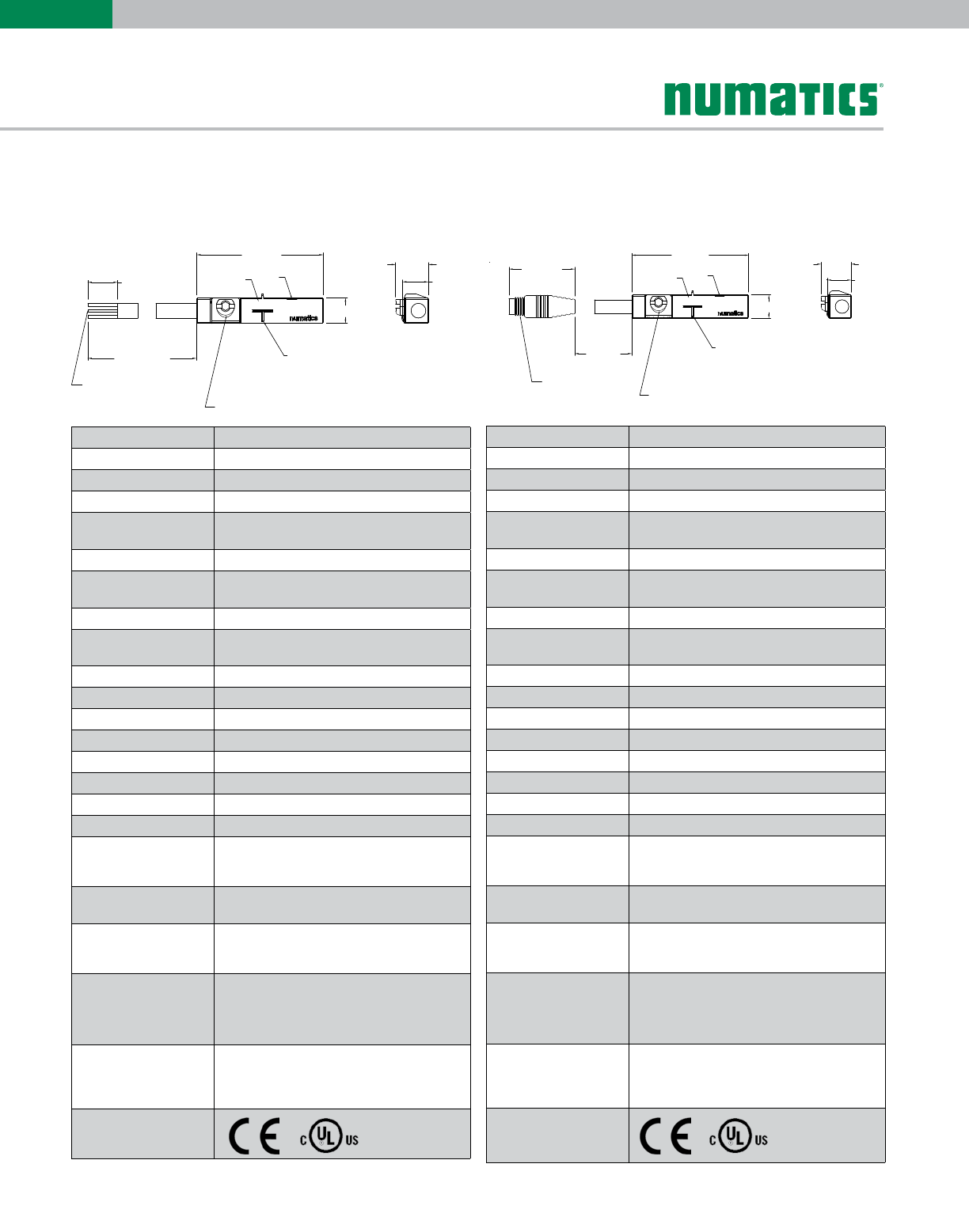
22
E
SERIES
ELECTRICAL DESIGN DC PNP
OUTPUT Normally Open
OPERATING VOLTAGE 10-30 VDC
CURRENT RATING 100 mA
SHORT-CIRCUIT
PROTECTION Yes
OVERLOAD PROTECTION Yes
REVERSE POLARITY
PROTECTION Yes
VOLTAGE DROP < 2.5 V
CURRENT CONSUMPTION < 12 mA
REPEATABILITY < .2mm
POWER-ON DELAY TIME < 30 ms
SWITCH FREQUENCY > 3000 Hz
AMBIENT TEMPERATURE -25ºC to 85ºC
PROTECTION IP 67, III
HYSTERESIS 1.0mm
MAGNETIC SENSITIVITY 2.0 mT
TRAVEL SPEED > 10 m/s
HOUSING MATERIAL PA (Polyamide) Black; Fastening Clamp:
Stainless Steel
FUNCTION DISPLAY
SWITCHING STATUS Yellow LED
CONNECTION Flying Leads, Pur Cable (2m Long, 3 x26 Gauge
Wire)
REMARKS
Clamping Screw with Combined Slot/Hexagon
Socket Head AF 1.5
cULus - Class 2 Source Required
ACCESSORIES Rubber Placehold, Cable Clip, and Cut Sheet
To Be Provided with Every Switch
AGENCY APPROVALS
ELECTRICAL DESIGN DC PNP
OUTPUT Normally Open
OPERATING VOLTAGE 10-30 VDC
CURRENT RATING 100 mA
SHORT-CIRCUIT
PROTECTION Yes
OVERLOAD PROTECTION Yes
REVERSE POLARITY
PROTECTION Yes
VOLTAGE DROP < 2.5 V
CURRENT CONSUMPTION < 12 mA
REPEATABILITY < .2mm
POWER-ON DELAY TIME < 30 ms
SWITCH FREQUENCY > 3000 Hz
AMBIENT TEMPERATURE -25ºC to 85ºC
PROTECTION IP 67, III
HYSTERESIS 1.0mm
MAGNETIC SENSITIVITY 2.0 mT
TRAVEL SPEED > 10 m/s
HOUSING MATERIAL PA (Polyamide) Black; Fastening Clamp:
Stainless Steel
FUNCTION DISPLAY
SWITCHING STATUS Yellow LED
CONNECTION M8 Connector (Snap Fit) , Pur Cable (.3 m)
REMARKS
Clamping Screw with Combined Slot/Hexagon
Socket Head AF 1.5
cULus - Class 2 Source Required
ACCESSORIES Rubber Placehold, Cable Clip, and Cut Sheet
To Be Provided with Every Switch
AGENCY APPROVALS
.98 [25.0]
.20 [5.0]
SENSING FACE
LED
PNP-QDS-M8-U
.25 [6.4]
.20 [5.1]
11.81 [300.0]
1.46 [37.0]
M8 x 1.0
PAR T
NUMBER
FASTENING CLAMP
.98 [25.0]
.20 [5.0]
FASTENING CLAMP
SENSING FACE
LED
PNP-FL2-00-U
.25 [6.4]
.20 [5.1]
PAR T
NUMBER
78.74 [2000.0]
1.50 [38.1]
BLUE (-)
BLACK (OUTPUT)
BROWN (+)
26 GAUGE WIRES
PNP-FL2-00-U PNP-QDS-M8-U
RoHS RoHS
Sensing Part Numbers
*Switches are not designed for wet environments. Please see your distributor for additional information.
Information subject to change without notice. For ordering information or regarding your local sales office visit www.numatics.com.
23
E
SERIES
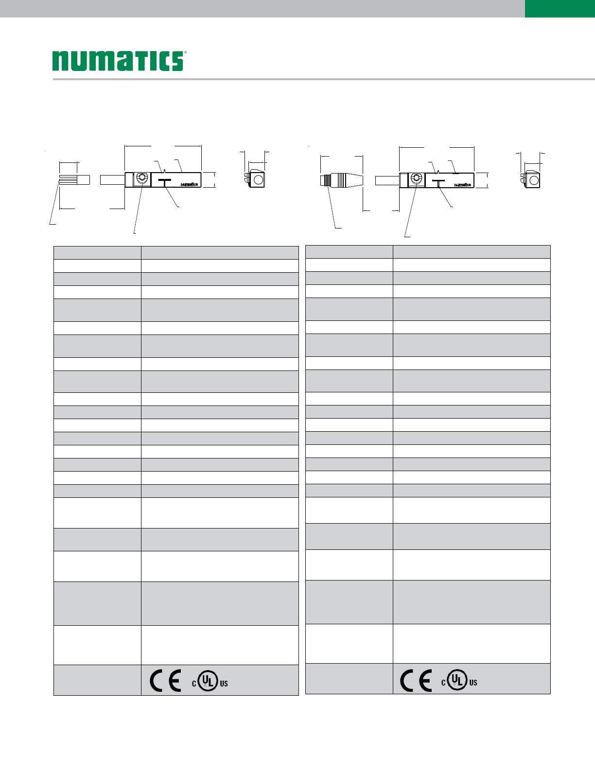
*Switches are not designed for wet environments. Please see your distributor for additional information.
ELECTRICAL DESIGN DC NPN
OUTPUT Normally Open
OPERATING VOLTAGE 10-30 VDC
CURRENT RATING 100 mA
SHORT-CIRCUIT
PROTECTION Yes
OVERLOAD PROTECTION Yes
REVERSE POLARITY
PROTECTION Yes
VOLTAGE DROP < 2.5 V
CURRENT CONSUMPTION < 12 mA
REPEATABILITY < .2mm
POWER-ON DELAY TIME < 30 ms
SWITCH FREQUENCY > 3000 Hz
AMBIENT TEMPERATURE -25ºC to 85ºC
PROTECTION IP 67, III
HYSTERESIS 1.0mm
MAGNETIC SENSITIVITY 2.0 mT
TRAVEL SPEED > 10 m/s
HOUSING MATERIAL PA (Polyamide) Black; Fastening Clamp:
Stainless Steel
FUNCTION DISPLAY
SWITCHING STATUS Yellow LED
CONNECTION M8 Connector (Snap Fit) , Pur Cable (.3 m)
REMARKS
Clamping Screw with Combined Slot/Hexagon
Socket Head AF 1.5
cULus - Class 2 Source Required
ACCESSORIES Rubber Placehold, Cable Clip, and Cut Sheet
To Be Provided with Every Switch
AGENCY APPROVALS
.98 [25.0]
.20 [5.0]
SENSING FACE
LED
NPN-QDS-M8-U
.25 [6.4]
.20 [5.1]
11.81 [300.0]
1.46 [37.0]
M8 x 1.0
PAR T
NUMBER
FASTENING CLAMP
ELECTRICAL DESIGN DC NPN
OUTPUT Normally Open
OPERATING VOLTAGE 10-30 VDC
CURRENT RATING 100 mA
SHORT-CIRCUIT
PROTECTION Yes
OVERLOAD PROTECTION Yes
REVERSE POLARITY
PROTECTION Yes
VOLTAGE DROP < 2.5 V
CURRENT CONSUMPTION < 12 mA
REPEATABILITY < .2mm
POWER-ON DELAY TIME < 30 ms
SWITCH FREQUENCY > 3000 Hz
AMBIENT TEMPERATURE -25ºC to 85ºC
PROTECTION IP 67, III
HYSTERESIS 1.0mm
MAGNETIC SENSITIVITY 2.0 mT
TRAVEL SPEED > 10 m/s
HOUSING MATERIAL PA (Polyamide) Black; Fastening Clamp:
Stainless Steel
FUNCTION DISPLAY
SWITCHING STATUS Yellow LED
CONNECTION Flying Leads, Pur Cable
(2m Long, 3 x26 Gauge Wire)
REMARKS
Clamping Screw with Combined Slot/Hexagon
Socket Head AF 1.5
cULus - Class 2 Source Required
ACCESSORIES Rubber Placehold, Cable Clip, and Cut Sheet
To Be Provided with Every Switch
AGENCY APPROVALS
.98 [25.0]
.20 [5.0]
SENSING FACE
LED
NPN-FL2-00-U
.25 [6.4]
.20 [5.1]
PAR T
NUMBER
78.74 [2000.0]
1.50 [38.1]
BLUE (-)
BLACK (OUTPUT)
BROWN (+)
26 GAUGE WIRES
FASTENING CLAMP
NPN-FL2-00-U NPN-QDS-M8-U
RoHS RoHS
Sensing Part Numbers
Information subject to change without notice. For ordering information or regarding your local sales office visit www.numatics.com.
24
E
SERIES
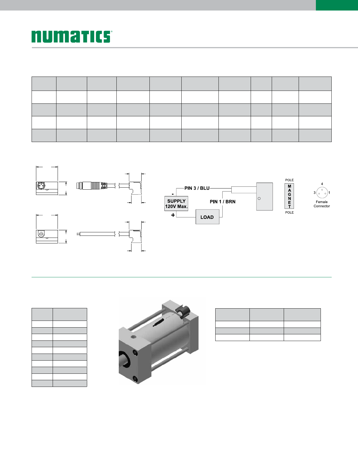
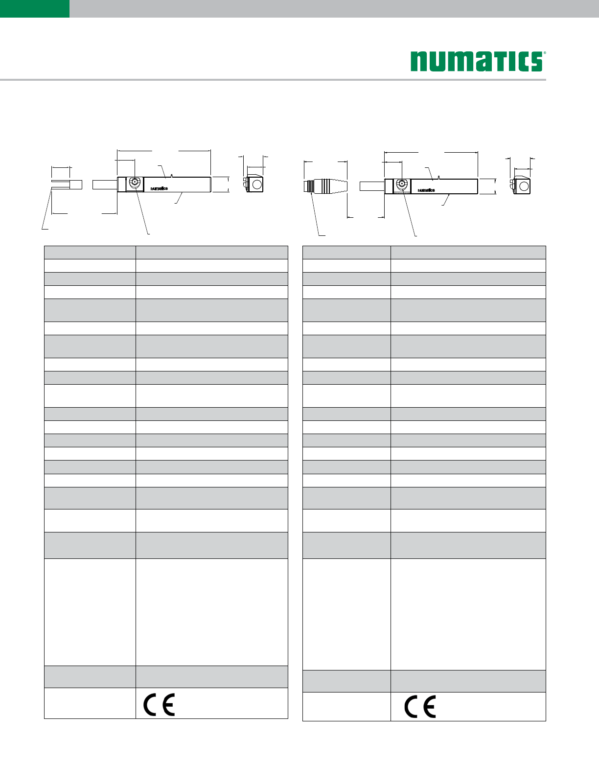
ELECTRICAL DESIGN AC/DC REED
OUTPUT Normally Open
OPERATING VOLTAGE 5-120 VAC/DC
CURRENT RATING 100 mA*
SHORT-CIRCUIT
PROTECTION No
OVERLOAD PROTECTION No
REVERSE POLARITY
PROTECTION Yes
VOLTAGE DROP < 5 V
REPEATABILITY ± .2mm
MAKETIME INCLUDING
BOUNCE < .6 ms
BREAKTIME < .1 ms
SWITCHING POWER (MAX) 5 W
SWITCH FREQUENCY 1000 Hz
AMBIENT TEMPERATURE -25ºC to 70ºC
PROTECTION IP 67, II
HYSTERESIS .9mm
HOUSING MATERIAL PA (Polyamide) Black; Fastening Clamp:
Stainless Steel
FUNCTION DISPLAY
SWITCHING STATUS Yellow LED
CONNECTION Flying Leads, Pur Cable
(2m Long, 2 x26 Gauge Wire)
REMARKS
*External Protective Circuit for Inductive Load
(Valve, Contactor, Etc..) Necessary.
Conforms to 2008 NEC Section 725 III,
Class 2 Circuits
Clamping Screw with Combined Slot/Hexagon
Socket Head AF 1.5.
No LED Function in case of Polarity in DC
Operation
ACCESSORIES Rubber Placehold, Cable Clip, and Cut Sheet
To Be Provided with Every Switch
AGENCY APPROVALS
ELECTRICAL DESIGN AC/DC REED
OUTPUT Normally Open
OPERATING VOLTAGE *5-60 VDC / 5-50 VAC
CURRENT RATING 100 mA
SHORT-CIRCUIT
PROTECTION No
OVERLOAD PROTECTION No
REVERSE POLARITY
PROTECTION Yes
VOLTAGE DROP < 5 V
REPEATABILITY ± .2mm
MAKETIME INCLUDING
BOUNCE < .6 ms
BREAKTIME < .1 ms
SWITCHING POWER (MAX) 5 W
SWITCH FREQUENCY 1000 Hz
AMBIENT TEMPERATURE -25ºC to 70ºC
PROTECTION IP 67, II
HYSTERESIS .9mm
HOUSING MATERIAL PA (Polyamide) Black; Fastening Clamp:
Stainless Steel
FUNCTION DISPLAY
SWITCHING STATUS Yellow LED
CONNECTION M8 Connector (Snap Fit), Pur Cable (.3m)
REMARKS *External Protective Circuit for Inductive Load
(Valve, Contactor, Etc..) Necessary.
Conforms to 2008 NEC Section 725 III,
Class 2 Circuits
M8 Connector voltage limited to 5-60 vdc / 5-50
vac to conform with 2008 IEC 61076-2-104
Clamping Screw with Combined Slot/Hexagon
Socket Head AF 1.5.
No LED Function in case of Polarity in DC
Operation
ACCESSORIES Rubber Placehold, Cable Clip, and Cut Sheet
To Be Provided with Every Switch
AGENCY APPROVALS
.25 [6.4]
.20 [5.1]
11.81 [300.0]
1.46 [37.0]
M8 x 1.0
1.20 [30.5]
.20 [5.0]
LED
REED-QDS-M8U
T AA
0809
PAR T
NUMBER
.22 [5.7]
FASTENING CLAMP
.25 [6.4]
.20 [5.1]
1.20 [30.5]
.20 [5.0]
LED
REED-FL2-00
T AA
0809
PAR T
NUMBER
.22 [5.7]
FASTENING CLAMP
78.74 [2000.0]
1.50 [38.1]
BLUE (-)
BROWN (+)
26 GAUGE WIRES
REED-FL2-00 REED-QDS-M8U
RoHS RoHS
Sensing Part Numbers
*Switches are not designed for wet environments. Please see your distributor for additional information.
Information subject to change without notice. For ordering information or regarding your local sales office visit www.numatics.com.
25
E
SERIES
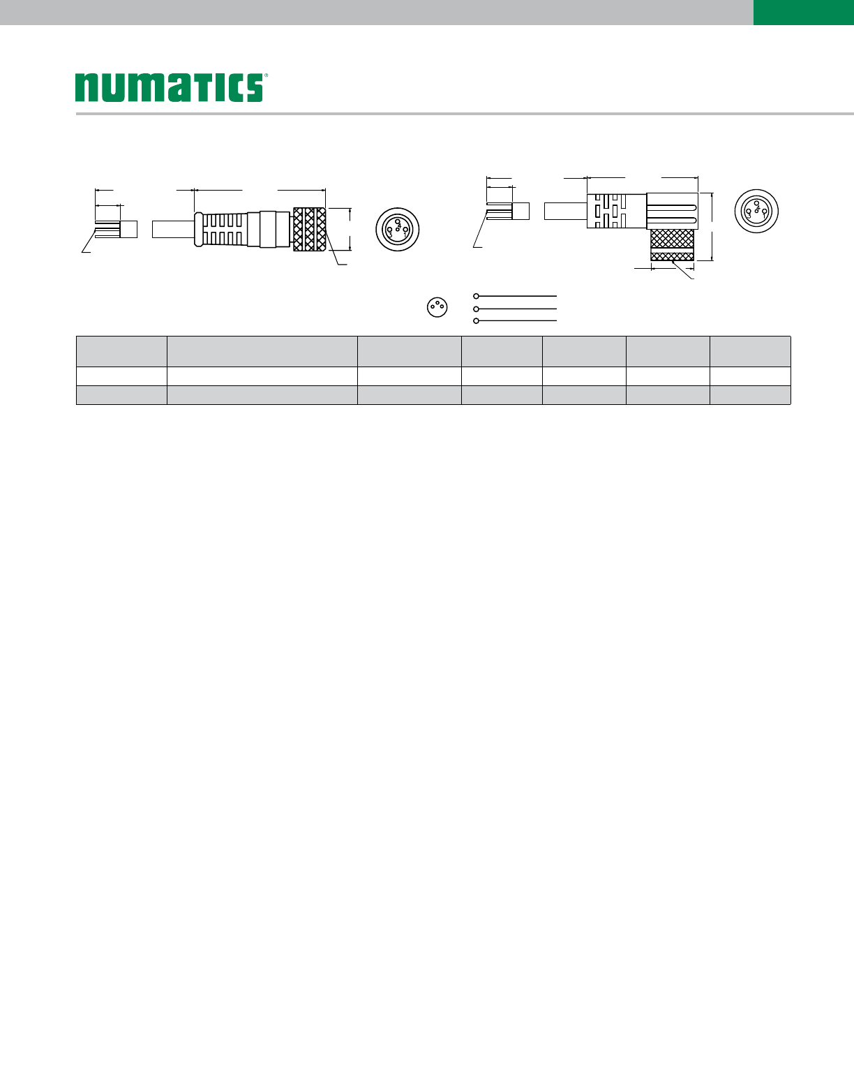
196.85 [5000]
BLUE (–)
BROWN (+)
BLACK (OUTPUT)
26 GAUGE WIRES
1.50 [38.1]
1.2 [31]
ø.4 [10]
M8 x 1
PXCST
Quick Disconnect Cables
Order Code Type Operating Voltage Current Rating Cable Material Protection Connector
PXCST Straight 5 m Cable (3 x 26 Gauge wire) 60 AC/75 DC 3 A PUR IP 68, III M8
PXC90 90° 5 m Cable (3 x 26 Gauge wire) 60 AC/75 DC 3 A PUR IP 68, III M8
BLUE (–)
BROWN (+)
BLACK (OUTPUT)
26 GAUGE WIRES
196.85 [5000] 1.06 [27]
.71 [18]
M8 x 1
ø.4 [10]
1.50 [38.1]
PXC90
Wiring
Core colors
BK black
BN brown
BU blue 13
4
1B
N
BU
BK
3
4

World Class Supplier of Pneumatic Components
World Headquarters
Numatics, Inc. | Tel (248) 596-3200 | www.numatics.com | email: insidesales@numatics.com
LT-ESeriesCatalog Rev 11/12
10M-IPC-1/09
© Numatics Inc. 2009 - 2012
Numatics® is registered in the United States and elsewhere
USA Numatics, Incorporated
46280 Dylan Drive
Novi, Michigan 48377
P: 248-596-3200
F: 248-596-3201
Canada Numatics, Ltd
P: 519-758-2700
F: 519-758-5540
Brazil Ascoval Ind.e Comercio Ltda
P: (55) 11-4208-1700
F: (55) 11-4195-3970
México - Ascomatica SA de CV
P: 52 55 58 09 56 40 (DF y Area metropolitana)
P: 01 800 000 ASCO (2726) (Interior de la República)
F: 52 55 58 09 56 60
