Flow Numatics G2 2 Fieldbus 1505490683 User Manual
Numatics G2-2 Fieldbus-1505490683 NUMATICS_G2-2_FIELDBUS-1505490683
Numatics Fieldbus-1505490641 NUMATICS_FIELDBUS-1505490641
Numatics Fieldbus-1505490641 NUMATICS_FIELDBUS-1505490641 NUMATICS_FIELDBUS-1505490641 NUMATICS FIELDBUS Fieldbus & IO s production assets-flotronics
2017-10-06
User Manual: Flow Numatics G2-2 Fieldbus-1505490683
Open the PDF directly: View PDF ![]() .
.
Page Count: 48
- Front Cover
- Table of Contents
- G2-1 Fieldbus Communications Electronics
- FlexiBlok® Manifold with Fieldbus Electronics Dimensional Drawing
- 25 Pin Female Sub-D Discrete Output and I/O Module
- I/O Modules Assemblies I/O Module Kit with Input LED Indicator (2 I/O per module)
- Manual Configuration Module (MCM)
- Fieldbus Communication Module and Manual Configuration Module Assemblies Communication Module
- LH Mounting Cover Kit
- AKC Communication Module
- How to Order
- Discrete I/O Modules
- Profibus DP (1.5 MBps & 12 MBps)
- Allen Bradley 1771 Remote I/O
- DeviceNet
- G2-2 Fieldbus Communications Electronics
- Outputs Distribution Boxes and I/O D-Boxes without Cable
- Input Distribution Boxes
- I/O Cables, Splitters and Accessories continued
- I/O Cables, Splitters and Accessories
- Sub-D Cables continued
- Sub-D Cables
- 12 and 26 Pole Cables and Connectors
- DeviceNet Trunk Cables, Drop Cables and Accessories continued
- DeviceNet Trunk Cables, Drop Cables and Accessories continued
- DeviceNet Trunk Cables, Drop Cables and Accessories
- 4 Pole Micro Power Cables for G2-1 Electronics
- Profibus Cables and Accessories (Reverse Key)
- Field Attachable Connectors 3, 4, and 5 Pole continued
- Field Attachable Connectors 3, 4, and 5 Pole
- 4 Pole Mini Power Cables for G2-2 Electronics
- Dimensional Drawing G2-2 Fieldbus Communication Assembly
- Right Mounting Cover Assembly
- Left Mounting Cover Assembly
- Dual 15 Pin Sub-D Output Module
- Single 25 Pin Sub-D Output Module
- Valve Side Sub-D Output Modules Dual 25 Pin Sub-D Output Module
- Dual 25 Pin Sub-D Connector Output Module with Aux. Power Connector
- 25 Pin Sub-D Connector Output Module w/Aux. Power Connector
- Dual 15 Pin Sub-D Connector Input
- 25 Pin Sub-D Connector Input
- I/O Block Assemblies
- Manual Configuration Module (MCM) Kit
- Fieldbus Communication Module and Manual Configuration Module Assemblies Communication Module Kit
- When Ordering: AKV Manifold Assembly Kit with Fieldbus Electronics Mark 8, 15 and 55 Series
- When Ordering: AKE ISO 5599/2 Series Manifold Assembly Kit with Fieldbus Electronics
- When Ordering: AKC Manifold Assembly Kit with Fieldbus Electronics 2005 and 2012 Series and ISO 15407-2 Series
- How to Order continued
- How to Order
- Discrete I/O Modules
- Profibus DP (1.5 MBps & 12 MBps)
- Interbus - S
- Ethernet
- DeviceLogix
- Allen Bradley 1771 Remote I/O
- ControlNet
- DeviceNet
- Back Cover


2Information subject to change without notice. For ordering information or regarding your local sales office visit www.numatics.com.
Fieldbus Electronics and I/O . . . . . . . . . . . . . . . . . . . . . . . . . . . . . . . . . . . . . . . . . . . . . . . . . .3-47
G2-1 Electronics . . . . . . . . . . . . . . . . . . . . . . . . . . . . . . . . . . . . . . . . . . . . . . . . . . . . . . . . . . . . . . . . . . . . .3-12
Features and Benefits . . . . . . . . . . . . . . . . . . . . . . . . . . . . . . . . . . . . . . . . . . . . . . . . . . . . . . . . . . . . . . . . . . . . . . . . . . . . . .3
Communication Protocols . . . . . . . . . . . . . . . . . . . . . . . . . . . . . . . . . . . . . . . . . . . . . . . . . . . . . . . . . . . . . . . . . . . . . . . . .4-7
How to Order . . . . . . . . . . . . . . . . . . . . . . . . . . . . . . . . . . . . . . . . . . . . . . . . . . . . . . . . . . . . . . . . . . . . . . . . . . . . . . . . . . .8-9
LH Mounting Cover Kit . . . . . . . . . . . . . . . . . . . . . . . . . . . . . . . . . . . . . . . . . . . . . . . . . . . . . . . . . . . . . . . . . . . . . . . . . . . . .9
Fieldbus Communication Module . . . . . . . . . . . . . . . . . . . . . . . . . . . . . . . . . . . . . . . . . . . . . . . . . . . . . . . . . . . . . . . . . . . . .10
Manual Configuration Module . . . . . . . . . . . . . . . . . . . . . . . . . . . . . . . . . . . . . . . . . . . . . . . . . . . . . . . . . . . . . . . . . . . . . . .10
I/O Module Assemblies . . . . . . . . . . . . . . . . . . . . . . . . . . . . . . . . . . . . . . . . . . . . . . . . . . . . . . . . . . . . . . . . . . . . . . . . . . . .11
Dimensional Drawing . . . . . . . . . . . . . . . . . . . . . . . . . . . . . . . . . . . . . . . . . . . . . . . . . . . . . . . . . . . . . . . . . . . . . . . . . . . . .12
G2-2 Electronics . . . . . . . . . . . . . . . . . . . . . . . . . . . . . . . . . . . . . . . . . . . . . . . . . . . . . . . . . . . . . . . . . . . .13-33
Features and Benefits . . . . . . . . . . . . . . . . . . . . . . . . . . . . . . . . . . . . . . . . . . . . . . . . . . . . . . . . . . . . . . . . . . . . . . . . . . . . .13
Communication Protocols . . . . . . . . . . . . . . . . . . . . . . . . . . . . . . . . . . . . . . . . . . . . . . . . . . . . . . . . . . . . . . . . . . . . . . . .14-20
Discrete I/O Modules . . . . . . . . . . . . . . . . . . . . . . . . . . . . . . . . . . . . . . . . . . . . . . . . . . . . . . . . . . . . . . . . . . . . . . . . . . . . .21
How to Order . . . . . . . . . . . . . . . . . . . . . . . . . . . . . . . . . . . . . . . . . . . . . . . . . . . . . . . . . . . . . . . . . . . . . . . . . . . . . . . . .22-26
Fieldbus Communication Module . . . . . . . . . . . . . . . . . . . . . . . . . . . . . . . . . . . . . . . . . . . . . . . . . . . . . . . . . . . . . . . . . . . . .27
Manual Configuration Module . . . . . . . . . . . . . . . . . . . . . . . . . . . . . . . . . . . . . . . . . . . . . . . . . . . . . . . . . . . . . . . . . . . . . . .27
I/O Block Assemblies . . . . . . . . . . . . . . . . . . . . . . . . . . . . . . . . . . . . . . . . . . . . . . . . . . . . . . . . . . . . . . . . . . . . . . . . . . . . .28
25 Pin Sub-D Connector Input . . . . . . . . . . . . . . . . . . . . . . . . . . . . . . . . . . . . . . . . . . . . . . . . . . . . . . . . . . . . . . . . . . . . . .29
Dual 15 Pin Sub-D Connector Input . . . . . . . . . . . . . . . . . . . . . . . . . . . . . . . . . . . . . . . . . . . . . . . . . . . . . . . . . . . . . . . . . .29
25 Pin Sub-D Connector Output Module . . . . . . . . . . . . . . . . . . . . . . . . . . . . . . . . . . . . . . . . . . . . . . . . . . . . . . . . . . . . . . .30
Dual 25 Pin Sub-D Connector Output Module . . . . . . . . . . . . . . . . . . . . . . . . . . . . . . . . . . . . . . . . . . . . . . . . . . . . . . . . . . .30
Valve Side Sub-D Output Modules . . . . . . . . . . . . . . . . . . . . . . . . . . . . . . . . . . . . . . . . . . . . . . . . . . . . . . . . . . . . . . . . . . .31
Mounting Cover Assemblies . . . . . . . . . . . . . . . . . . . . . . . . . . . . . . . . . . . . . . . . . . . . . . . . . . . . . . . . . . . . . . . . . . . . . . . .32
Dimensional Drawing . . . . . . . . . . . . . . . . . . . . . . . . . . . . . . . . . . . . . . . . . . . . . . . . . . . . . . . . . . . . . . . . . . . . . . . . . . . . .33
Cables and Accessories . . . . . . . . . . . . . . . . . . . . . . . . . . . . . . . . . . . . . . . . . . . . . . . . . . . . . . . . . .34-47
©Numatics 2004
Rev. 2/04
G2-1 Electronics
3
Information subject to change without notice. For ordering information or regarding your local sales office visit www.numatics.com.
G2-1 Fieldbus Communications Electronics
Why use Numatics Fieldbus communication
electronics? Modular Reality...
• No internal wiring
• Up to 40 valve solenoids
• Discrete I/O status with short circuit protection
• Software or manual configuration
• Plug-together flexibility
• Conformance tested
• Shorted and open load diagnostics
• Universal input technology allows
NPN or PNP sensor types with same input module.
• NEMA4/IP65
• Up to 16 discrete output points and
16 input points per communication node
• Low cost distribution options
• Used with 2002 Series
Supported Protocols:
• DeviceNet
• Allen Bradley 1771 Remote I/O
• Profibus DP 1.5 MBps & 12MBps
• DeviceLogix
• CANopen - Consult Factory
G2-1 Electronics
4Information subject to change without notice. For ordering information or regarding your local sales office visit www.numatics.com.
DeviceNet
DeviceNet is an open protocol bus communication
system developed by Allen-Bradley based on
Controller Area Network (CAN) technology. The gov-
erning body for DeviceNet is the Open DeviceNet
Vender Association (ODVA). The ODVA controls the
DeviceNet specification and oversees product con-
formance testing.
Numatics G2-1 DeviceNet modes have been tested
and approved for conformance by the ODVA.
More information about DeviceNet and the ODVA
can be obtained from the following WEB site:
Open DeviceNet Vendors Association (ODVA)
www.odva.org
Technical Data
ELECTRICAL DATA VOLTAGE CURRENT
BUS Power 11-25 VDC 0.025 amps.
Valve & Discrete I/O 24 VDC +/- 10% 4 amps. maximum
OPERATING DATA
Temperature Range +32˚ to +115˚ F (0˚ to +46˚ C)
Humidity 95% relative humidity, non-condensing
Moisture Designed to meet NEMA 4 / IP65 requirements
Maximum Valve Solenoid Outputs 24
CONFIGURATION DATA
Communication Module Contains all communication electronics as well as short circuit protected driver circuitry for up to
24 valve solenoids. Supports auto-baud detection and auto-device replacement (ADR) feature.
Manual Configuration Module (MCM) Optional module for use when a manual configuration method is
preferred.
Electronic Data Sheet (EDS) file and technical manuals are available in the download section of the Numatics, Inc.
web site at: www.numatics.com/fieldbus
Maximum Discrete I/O Points 16
Aux Power Connector Single key way 4 pole 12mm (Micro) connector
LED’s Module status, Network status, Ext fault & Aux power
Communication Connector Single key way 5 pole 12 mm (Micro) connector
Numatics’ DeviceNet modules features polled, change of state (COS), cyclic and combinations message capability.
G2-1 Electronics
5
Information subject to change without notice. For ordering information or regarding your local sales office visit www.numatics.com.
Allen Bradley 1771 Remote I/O
Allen-Bradley 1771 Remote I/O is a
proprietary protocol based on a
patented chipset.
This chipset is obtained from
Allen-Bradley and incorporated into
the Numatics RIO module.
Technical Data
ELECTRICAL DATA VOLTAGE CURRENT
Valve & Discrete I/O 24 VDC +/- 10% 4 amps. maximum
OPERATING DATA
Temperature Range +32˚ to +115˚ F (0˚ to +46˚ C)
Humidity 95% relative humidity, non-condensing
Moisture Designed to meet NEMA 4 / IP65 requirements
Maximum Valve Solenoid Outputs 24
CONFIGURATION DATA
Communication Module Contains all communication electronics as well as short circuit protected driver circuitry
for up to 24 valve solenoids.
Rack Size Rack size set automatically to 1/4 rack
Manual Configuration Module (MCM) Module contains DIP and rotary switches for setting device configuration data
Maximum Discrete I/O Points 16
Aux Power Connector Single key way 4 & 5 pole 12mm (Micro) connector
Communication Connector Single key way 5 pole 12 mm (Micro) connector, Bus in and out
LED’s Communications status, ext. fault and auxiliary power
This product incorporates technology which is licensed by Allen- Bradley Company, Inc. Allen-Bradley
has not technically approved, nor does it warrant or support this product. All warranty and support for
this product and its application is provided solely by Numatics, Incorporated.
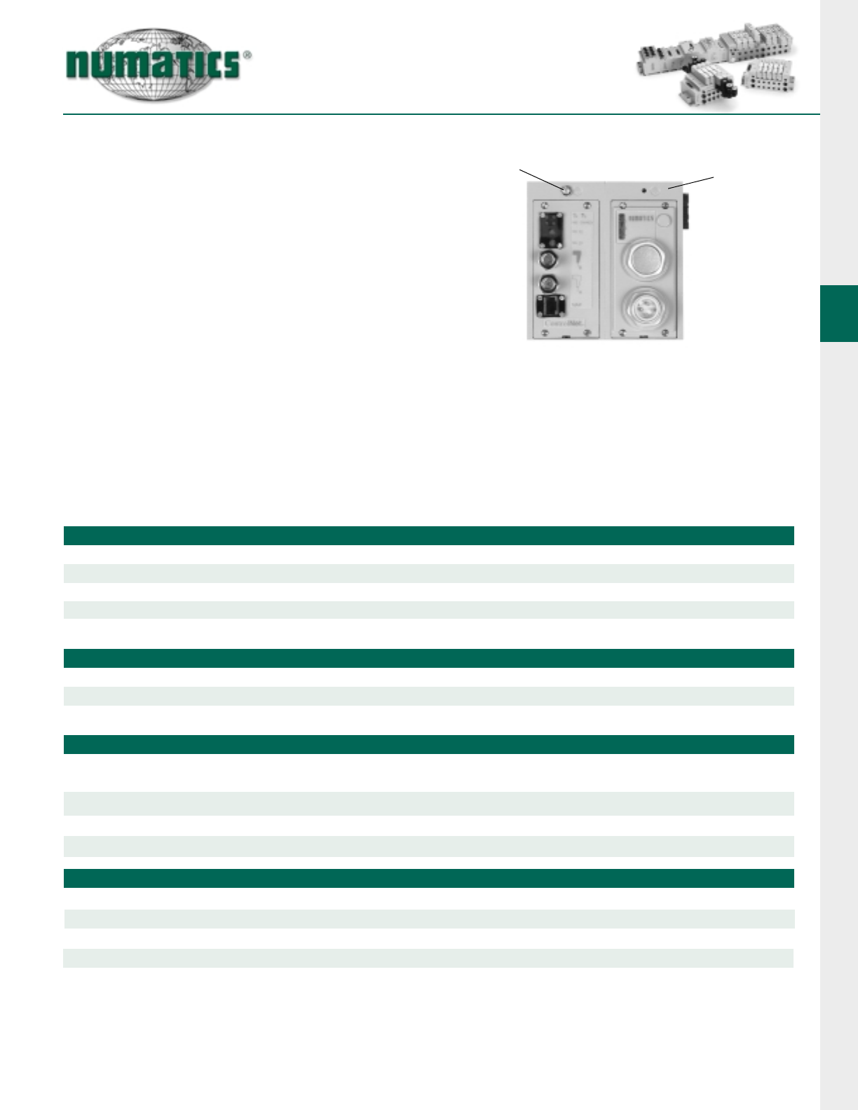
Communication
Module
Manual Configuration Module
(MCM) (Required)
G2-1 Electronics
6Information subject to change without notice. For ordering information or regarding your local sales office visit www.numatics.com.
Technical Data
ELECTRICAL DATA VOLTAGE CURRENT
Valve & Discrete I/O 24 VDC +/- 10% 4 amps. maximum
LED’s Module status, Network status, Ext fault and Auxiliary power
OPERATING DATA
Temperature Range +32˚ to +115˚ F (0˚ to +46˚ C)
Humidity 95% relative humidity, non-condensing
Moisture Designed to meet NEMA 4 / IP65 requirements
Maximum Valve Solenoid Outputs 24
CONFIGURATION DATA
Communication Module Contains all communication electronics as well as short circuit protected driver circuitry
for up to 24 valve solenoids.
Manual Configuration Module (MCM) Module containing DIP and rotary switches for setting device configuration data.
Aux. Power Connectors 1.5 MBps Single key way 4 pole 12 mm (Micro) connector
12 MBps Single key way 4 pole 12 mm (Micro) connector
Communication Connector 1.5 MBps 5 pole 12 mm (Micro) connector
12 MBps 5 pole reverse key female (Micro) connector
Maximum Discrete I/O Points 16, available with 12mm (micro) connectors or 25 pin sub-D styles
Profibus DP (1.5 MBps & 12 MBps)
Profibus-DP is a vendor-independent, open
fieldbus designed for communication between
automation control systems and distributed I/O
at the device level.
The 2002 Series - Profibus product is designed
to conform to the Profibus standard EN50170.
Certification is by the Profibus Interface Center
(PIC) according to the guidelines determined by
the Profibus Trade Organization (PTO). The cer-
tification process ensures interoperability for all
Profibus devices.
More information about Profibus can be
obtained at the following web sites:
Profibus Interface Center
www.aut.sea.siemens.com/pic/index.htm
Profibus Trade Organization
www.profibus.com Communication Module
Manual Configuration Module
(MCM) (Not required with Class II Master)
(GSD) File and technical manuals are available in the download section of the Numatics, Inc.
website at: www.numatics.com/fieldbus.
G2-1 Electronics
7
Information subject to change without notice. For ordering information or regarding your local sales office visit www.numatics.com.
The maximum number of modules connected to the discrete I/O side is 8. A fully configured manifold assembly would require 2 master modules with 6 slaves.
Discrete I/O Modules
Discrete I/O modules are used to connect addi-
tional I/O devices to the valve manifold
node. This provides for more efficient use of
system resources when configuring a communi-
cation system.
Universal input modules feature technology that
allows the same module to automatically recog-
nize PNP or NPN type sensors without the need
to add external pull-up resistors or manually
select sensor type.
Input and output modules have two 12mm
(micro) connectors. Each can be used individual-
ly (i.e. 1 I/O point per connector) or can be used
for double point (i.e. connector 1 has two points
of I/O). This standard feature further simplifies
external I/O wiring.
Sub-D output module can be used to drive 16
additional coils on a separate manifold or 16 dis-
crete output points.
Sub-D I/O module can be used for inputs and or
up to a total of 16 I/O points.
Discrete I/O
Technical Data
ELECTRICAL DATA
Inputs:
Supply Voltage 24 VDC ± 10%
Type Sourcing (PNP), Sinking (NPN) or contact closure (universal input technology)
LED Indicator Input status
Outputs:
Voltage 24 VDC +/- 10%
Current 0.5 amperes per output (4A max. per manifold)
Type Sinking (NPN)
LED Indicator Output status
OPERATING DATA
Temperature Range +32˚ to +115˚ F (0˚ to +46˚ C)
Humidity 95% relative humidity, non-condensing
Moisture Designed to meet NEMA 4 / IP65 requirements
Connectors Single keyway 5 pole female 12mm (micro) connector or 25 pin sub-D female
CONFIGURATION DATA
Sub-D I/O
E02
6
Electrical / Electronic
Type & Location
C = Communication Module
Valve Series
6 = 2002 Series
Number of Valve Stations*
A=1
B=2
C=3
D=4
E=5
F=6
G=7
H=8
AKC 0 0
Options
STD = Standard
DRM = DIN Rail Mounting (Std. 35mm)
MUF = Muffler in End Plates
DWM= DIN Rail with MUF
A01 = 25 Pin Sub-D 16 Discrete
Outputs Sinking (NPN)
D01 = A01 + DRM
D03 = A01 + MUF
F01 = A01 + DRM + MUF
A17 = 25 Pin Sub-D 16 I/O Points
Inputs Sourcing (PNP)
Outputs Sinking (NPN)
D18 = A17 + DRM
D19 = A17 + MUF
F07 = A17 + DRM + MUF
00
I = 9
J=10
K=11
L=12
M= 13
N=14
O= 15
P=16
Q= 17
R=18
S=19
T=20
U=21
V=22
W= 23
X=24
End Plate
Port Size
2 = 1/4
H = 8mm (5/16)
Port Type
L = Push In
D = Barbed Fitting
DF
Fieldbus Protocols
DN = DeviceNet™
AB = Allen Bradley RIO
PB = Profibus DP 1.5 MBps
PT = Profibus DP 12 MBps
DL = DeviceLogix
Number of
Discrete Inputs**
Number of
Discrete Outputs**
NX6
Options
E02 = Separate Power
(Valve and I/O)
G08 = With MCM if Not Standard
STD = Standard
Voltage
F = 24 VDC
I/O Type
D = Digital
G2-1 Electronics
8Information subject to change without notice. For ordering information or regarding your local sales office visit www.numatics.com.
* Maximum number of valve stations is determined by the combination of single
and double Z-Boards types installed in the manifold sub-bases. All G2-1 communication
modules support 24 output drivers for valve solenoid coils.
2) Valve Model Number Selection
Valve model number with plug-in manifold base and “G” wiring option.
3) Electronic Interface
How to Order
1) Assembly Kit Selection
**4) I/O Per I/O Station – Electronic Interface Option Only (See I/O table below)
When ordering up to eight (8) I/O you must order one (1) Master I/O (which contains two (2) points I/O
itself). The balance required is made up of Slaves, two (2) points per I/O station (total 3 Slave modules). A
maximum of sixteen (16) I/O points can be configured by using two (2) Master modules and six (6) Slave
modules. Total number of discrete inputs plus total number of discrete outputs must be less than or equal
to 16. (See I/O table below).
Input master modules can be used with Output Slave Modules.
Output master Modules can be used with Input Slave Modules.
Sub-D outputs and I/O types do not require additional master modules when used alone
I/O Table: Note 2 I/O per station
HOUSING TYPE SINKING (NPN) OUTPUT SINKING (NPN) or
SOURCING (PNP) INPUT
Master Kit No.
Slave Kit No.
239-1800 239-1802
239-1801 239-1803
G2-1 Electronics
9
Information subject to change without notice. For ordering information or regarding your local sales office visit www.numatics.com.
AKC Communication Module
LH Mounting Cover Kit
• Shaded components described by Assembly Kit (AK) model number designation (see #1, pg. 8), with the exception
of the Communication module and number of I/O stations that are described by Electronic Interface (NX6) model
number designation. (see #3, pg. 8)
• Each valve manifold station is listed in sequential order from left to right when facing the port side of the manifold
as indicated.
• Each discrete I/O station is listed in sequential order from RIGHT to LEFT starting from the Communication mod-
ule as indicated.
NOTE: I/O stations #1 and #5 (if required) must always be a MASTER KIT. (see #4, pg. 8)
Stations 2,3,4,6,7 and 8 must be either input or output Slave kits.
NOTE: Total of 24 solenoid outputs available. Either 24 single solenoid valves or 12 double solenoid valves or any
combination of singles or doubles, not to exceed 24 solenoid outputs for AKC Serial/Bus are allowed.
valve
stations:
I/O
stations:
Serial Bus
Module NX6 12
.... 24
21
...........
8
Example order: AKC6D00002LSTD
021BW4Z3GL00061
021BW4Z3GL00061
021BB4Z4GL00061
021BB4Z4GL00061
NX6DN0808DFE02
I/O station 1 239-1802 Input Master Sinking (NPN) Kit
I/O station 2 239-1803 Input Slave Sinking (NPN) Kit
I/O station 3 239-1803 Input Slave Sourcing (PNP) Kit
I/O station 4 239-1803 Input Slave Sourcing (PNP) Kit
I/O station 5 239-1800 Output Master Sinking (NPN) Kit
I/O station 6 239-1801 Output Slave Sinking (NPN) Kit
I/O station 7 239-1801 Output Slave Sinking (NPN) Kit
I/O station 8 239-1801 Output Slave Sinking (NPN) Kit
ASSEMBLED
DET.
NO. NO.
REQ’D PART NAME PART NO.
1
2
3
4
5
6
1
2
2
2
2
2
LH DIN Rail Mtg Cover
Screw
Lockwasher
Screw
Spring
Clamp
127-844
128-192
127-472
115-355
125-720
105-381
LH MOUNTING COVER KIT
With DIN Rail
Without DIN Rail
PART NO.
239-1819
239-1820
G2-1 Electronics
10 Information subject to change without notice. For ordering information or regarding your local sales office visit www.numatics.com.
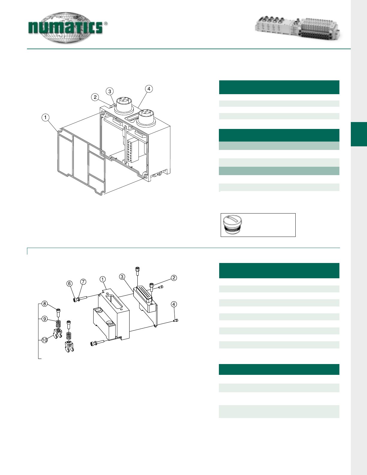
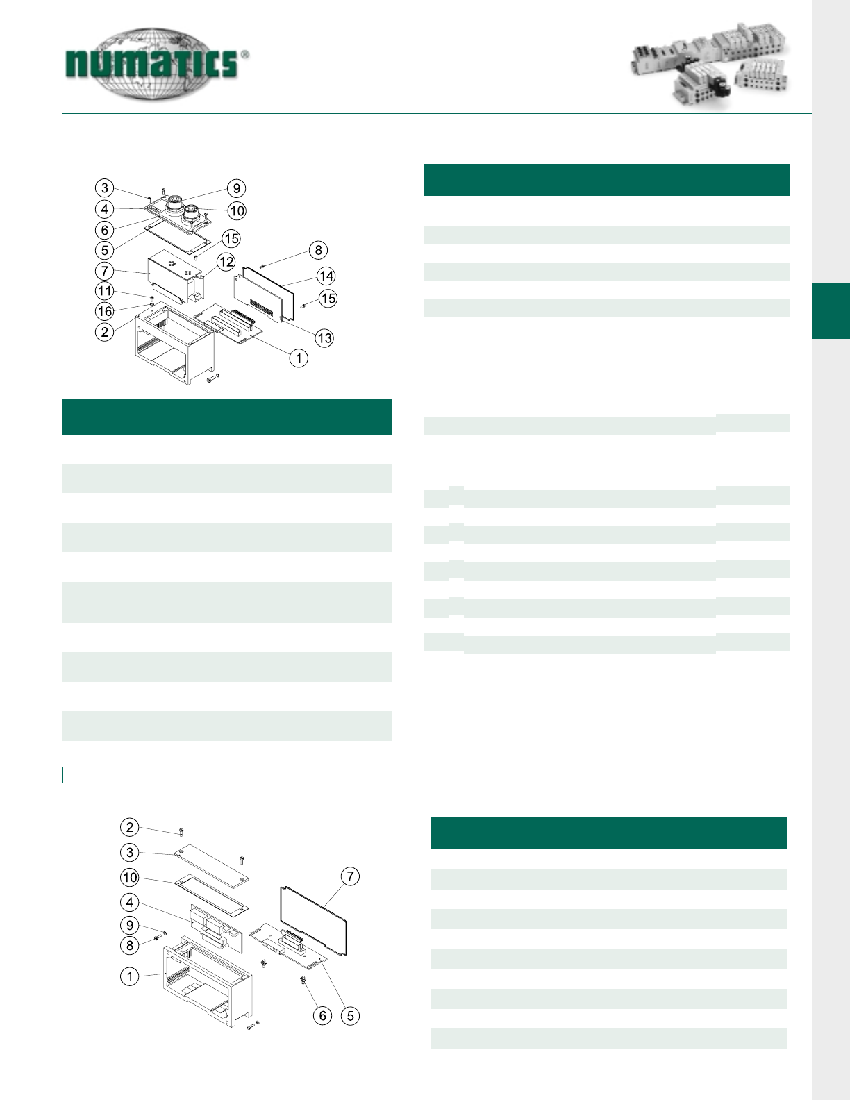
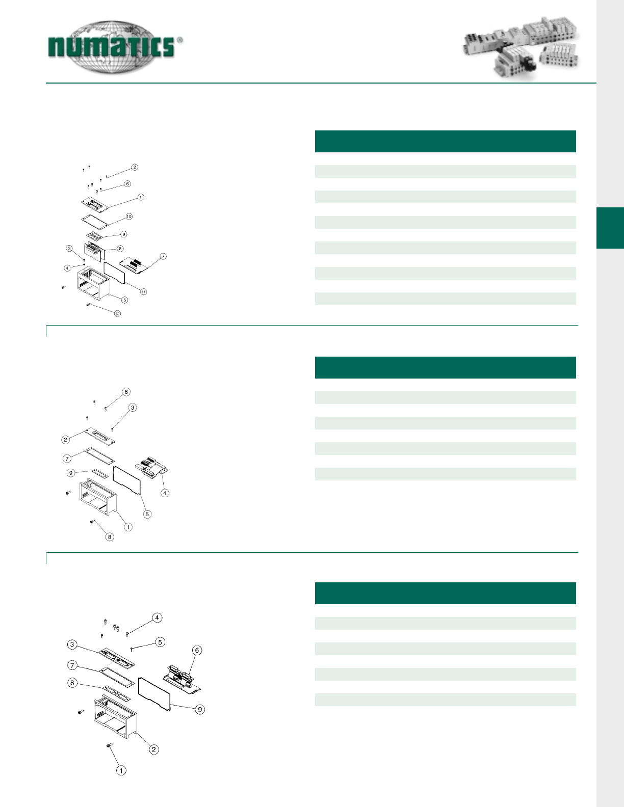
Fieldbus Communication Module and Manual Configuration Module Assemblies
Communication Module
123
4510
8976
Optional Bus Out Connector
(A-B 1771 RIO only)
Manual Configuration Module (MCM)
Manual Configuration Module Kits
(w/o End Plates)
Communication Module Kits
(w/o End Plates)
DET.
NO. NO.
REQ’D PART NAME PART NO.
1
2
3
3
3
4
5
6
7
8
1
3
1
1
1
2
2
1
1
1
Gasket
Screw
Nameplate (DeviceNet)
Nameplate (Profibus)
Nameplate (Allen Bradley RIO)
Screw
Lockwasher
Housing
Nameplate
Screw
127-794
122-1122
122-1123
122-1124
127-795
128-192
125-1017
122-1058
127-176
113-503
DET.
NO. NO.
REQ’D PART NAME PART NO.
1
2
5
6
7
8
1
4
2
1
1
1
Switch Housing w/ conn.
Screw
Screw
Cover w/ conn.
Gasket w/conn.
Gasket
127-794
127-852
105-399
113-529
113-503
125-800
10 1Cover Strap 125-772
12 2Screw 127-795
14 1
Nameplate (Conn Ver. Only)
122-1058
9
13
1Screw 127-172
2 Lockwasher 126-192
DESCRIPTION PART NO.
With Connector (A-B 1771 RIO only)
Without Connector 239-1813
239-1812
9
10
1
1
Cup Washer
Transfer Board
128-162
256-589
DESCRIPTION PART NO.
DeviceNet
Remote I/O
Profibus 1.5 Mbps
Profibus 12 Mbps
239-1804
239-1805
239-1806
239-1794
1 1
Switch Housing w/o conn.
125-1038
6 1 Cover w/o conn.
7 1 Gasket w/o conn.
105-384
113-508
DeviceLogix 239-2108
CANopen Consult Factory
G2-1 Electronics
11
Information subject to change without notice. For ordering information or regarding your local sales office visit www.numatics.com.
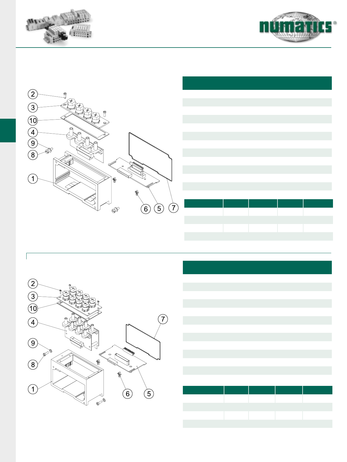
I/O Modules Assemblies
I/O Module Kit with Input LED Indicator (2 I/O per module)
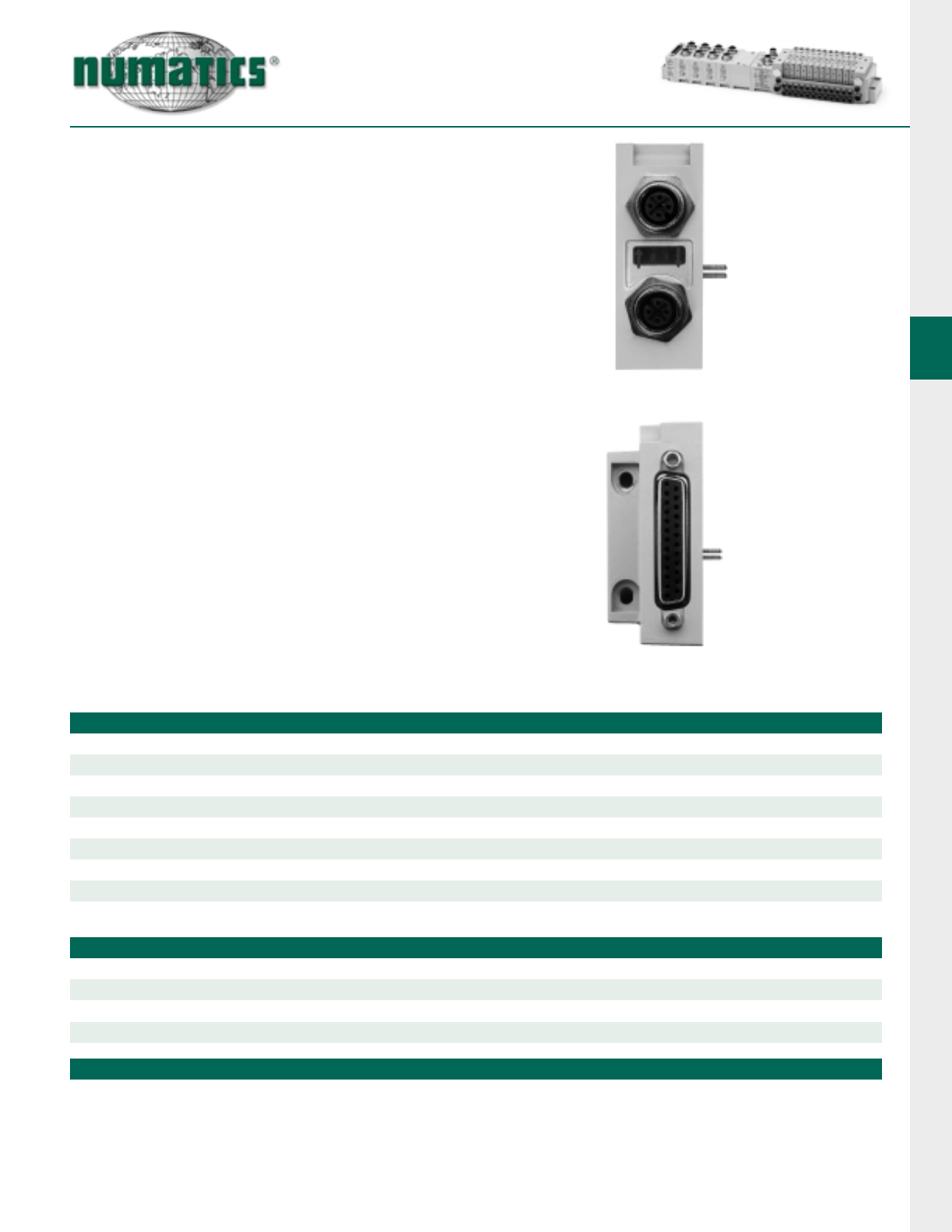
Discrete output and I/O Module Kit
25 Pin Female Sub-D Discrete Output and I/O Module
DIN RAIL OPTION ONLY
Dust cover available
for connectors:
PART NO. 230-647
DET.
NO. NO.
REQ’D PART NAME PART NO.
1
2
3
4
1
2
2
1
Gasket
Screw
Lockwasher
Housing
127-795
128-192
125-807
113-503
DET.
NO. NO.
REQ’D PART NAME PART NO.
1
2
3
4
6
7
8
9
10
1
2
1
2
1
2
2
2
2
Housing
Hex Screw
Gasket
Screw
Nameplate
Screw
Lockwasher
Screw (w/DIN)
Spring (w/DIN)
127-825
113-507
127-794
122-1057
127-499
128-192
127-472
115-355
105-379
11 2Clamp (w/DIN) 125-720
DESCRIPTION PART NO.
16 pt. Output Sinking (NPN) with DIN Rail
16 pt. Output Sinking (NPN) w/o DIN Rail 239-1221
239-1225
16 pt. Input Sourcing (PNP) and/or Output
Sinking (NPN) with DIN Rail
16 pt. Input Sourcing (PNP) and/or Output
Sinking (NPN) w/o DIN Rail
239-1866
239-1865
HOUSING TYPE OUTPUT
Output - Sinking (NPN) 239-1800
Slave Kit No.
Output - Sinking (NPN)
Input - Sinking (NPN) or Sourcing (PNP)
239-1801
239-1803
Connector Type
I/O 12 mm (Micro) 5 Pin Female
Note: When ordering this module in an assembled
manifold “AK” use the corresponding option code in the
“AK” model number. Do not list the module part number
under the Electronic Interface model number “NX”.
Master Kit No.
Input - Sinking (NPN) or Sourcing (PNP) 239-1802
G2-1 Electronics
12 Information subject to change without notice. For ordering information or regarding your local sales office visit www.numatics.com.
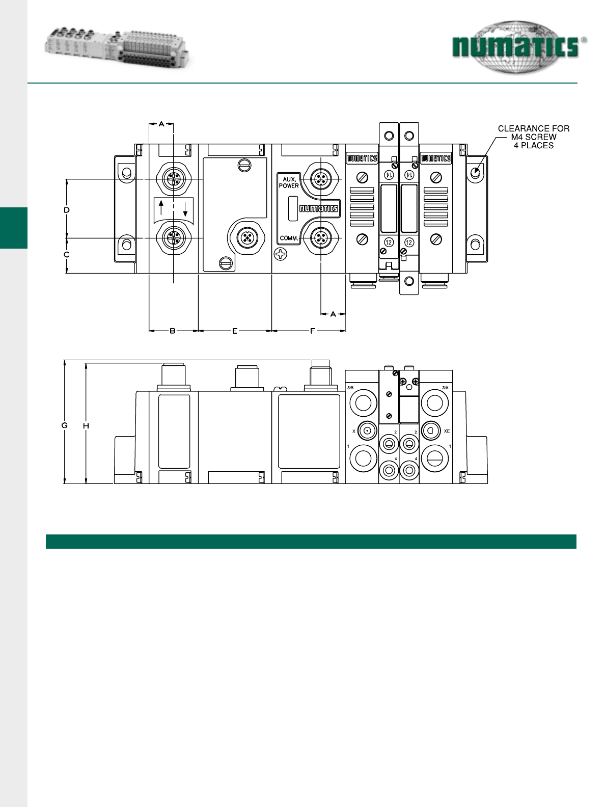
FlexiBlok®Manifold with Fieldbus Electronics Dimensional Drawing
A B C D E F G H
0.50
(12.7) 1.00
(25.4) 0.72
(18.3) 1.20
(30.5) 1.50
(38.1) 1.50
(38.1) 2.38
(60.5) 2.32
(59.0)
Dimensions
top dimensions = inches
bottom dimensions (in parenthesis) = millimeters
G2-2 Electronics
13
Information subject to change without notice. For ordering information or regarding your local sales office visit www.numatics.com.
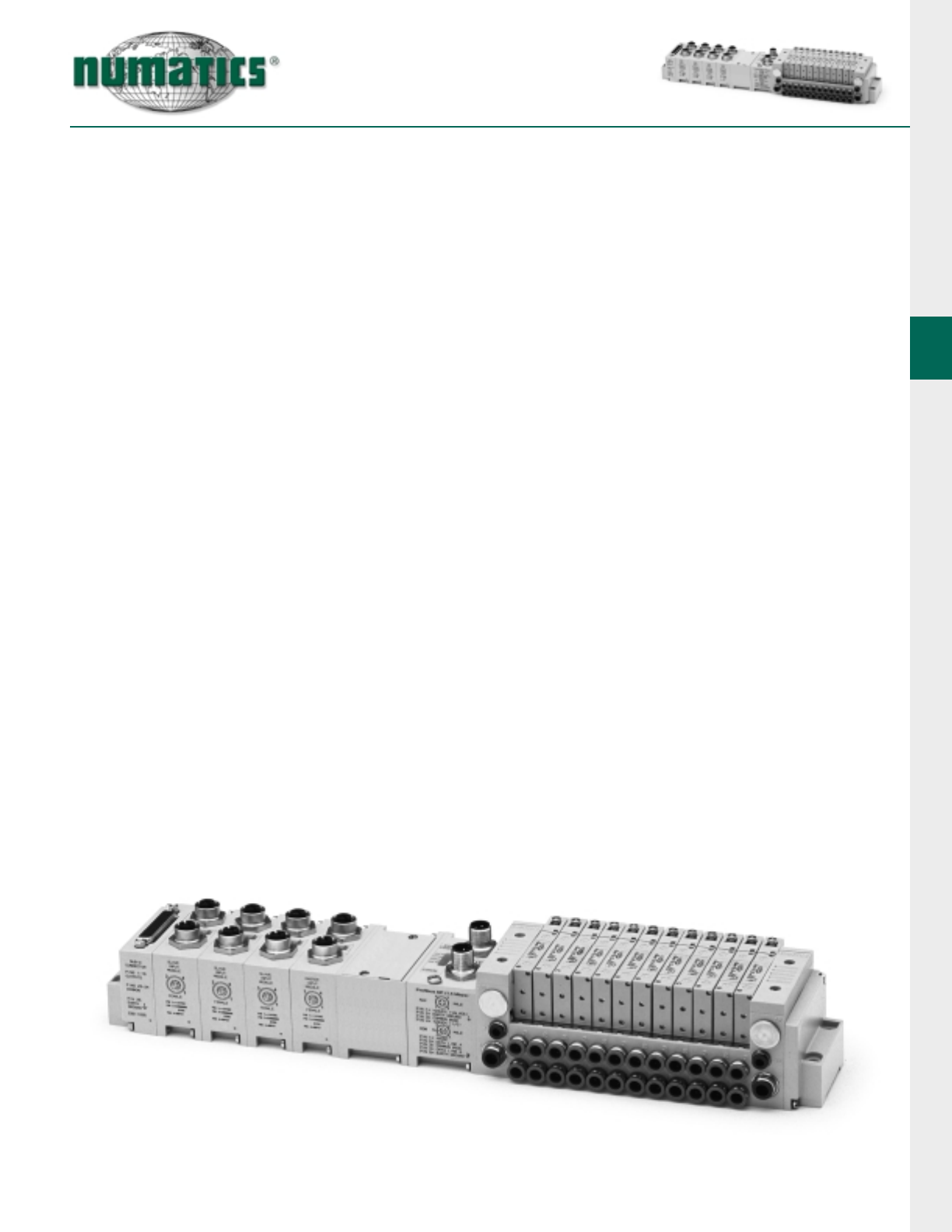
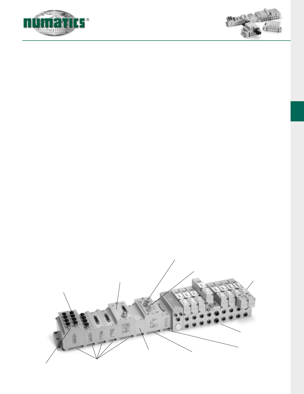
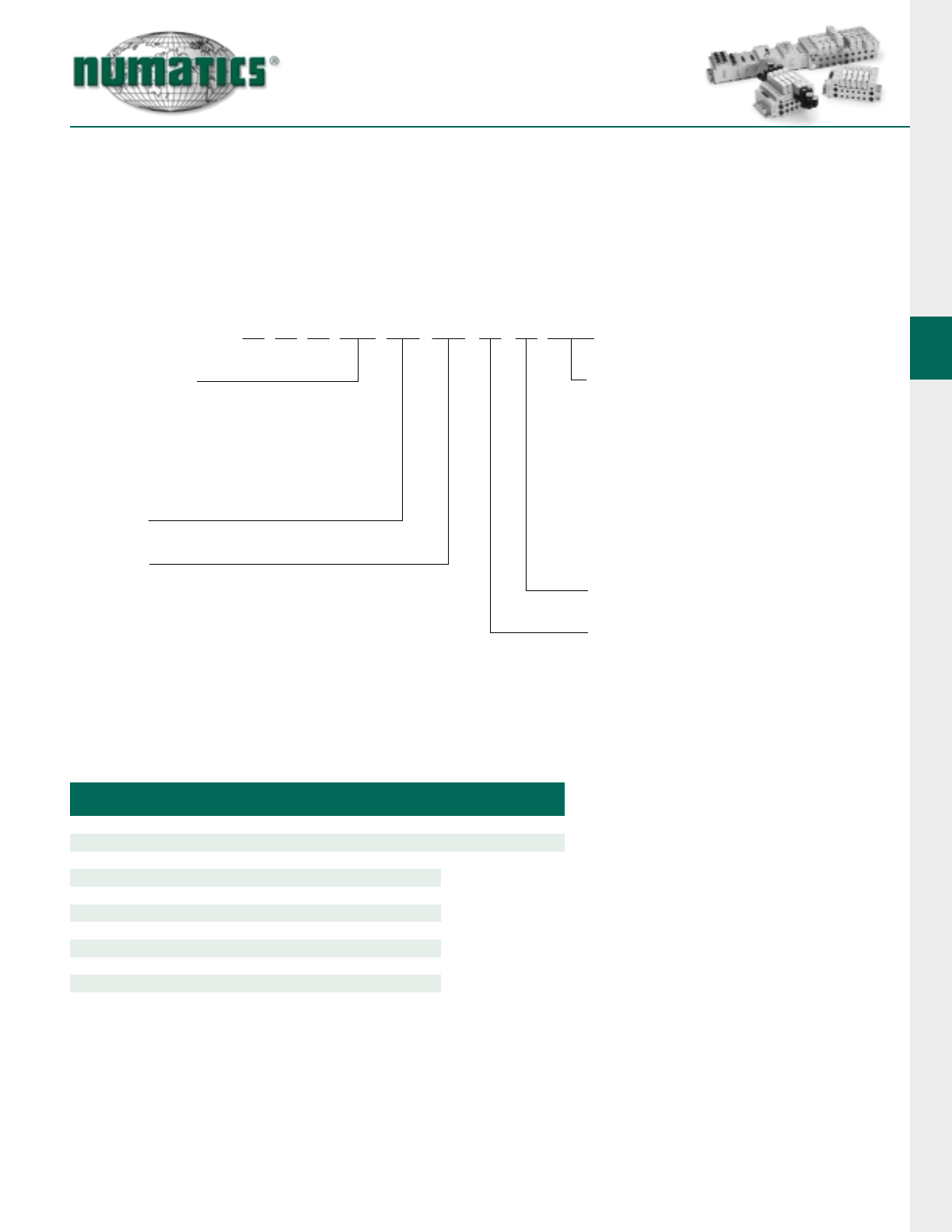
G2-2 Fieldbus Communications Electronics
Why use Numatics Fieldbus communication electronics? Modular Reality
• No internal wiring simplifies assembly
• Up to 192 discrete output points and 32 valve solenoids and
96 input points per communication mode
• Enhanced diagnostics include discrete I/O status with short circuit protection
• Software or manual configuration simplifies commissioning
• Plug-together flexibility
• Backplane technology allows fast maintenance
• Conformance tested ensures compatibility
• Shorted and open load diagnostics
• NPN and PNP discrete I/O modules
• NEMA 4/IP65 protected against water splash
• Low cost distribution options provide economic solutions for applications
• DIN rail mountable
Supported Protocols:
• Allen Bradley 1771 Remote I/O
• ControlNet
• DeviceNet
• DeviceNet with DeviceLogix
• Ethernet
• Interbus-S
• Profibus DP 1.5 MBps & 12MBps
• ASI - Consult Factory
Auxiliary Power Connector
Mid-Station
Supply & Exhaust
Block
Valve Manifold
Assembly
Discrete
I/O Connectors
Single or Double Point
LED Status Indicator
Communication
Connector
25 Pin Sub-D
Connector Output
Module w/ Auxiliary
Power Connector
Communication
Module
Manual
Configuration
Module
Discrete I/O Modules
Valve Side Sub-D
Output Module
G2-2 Electronics
14 Information subject to change without notice. For ordering information or regarding your local sales office visit www.numatics.com.
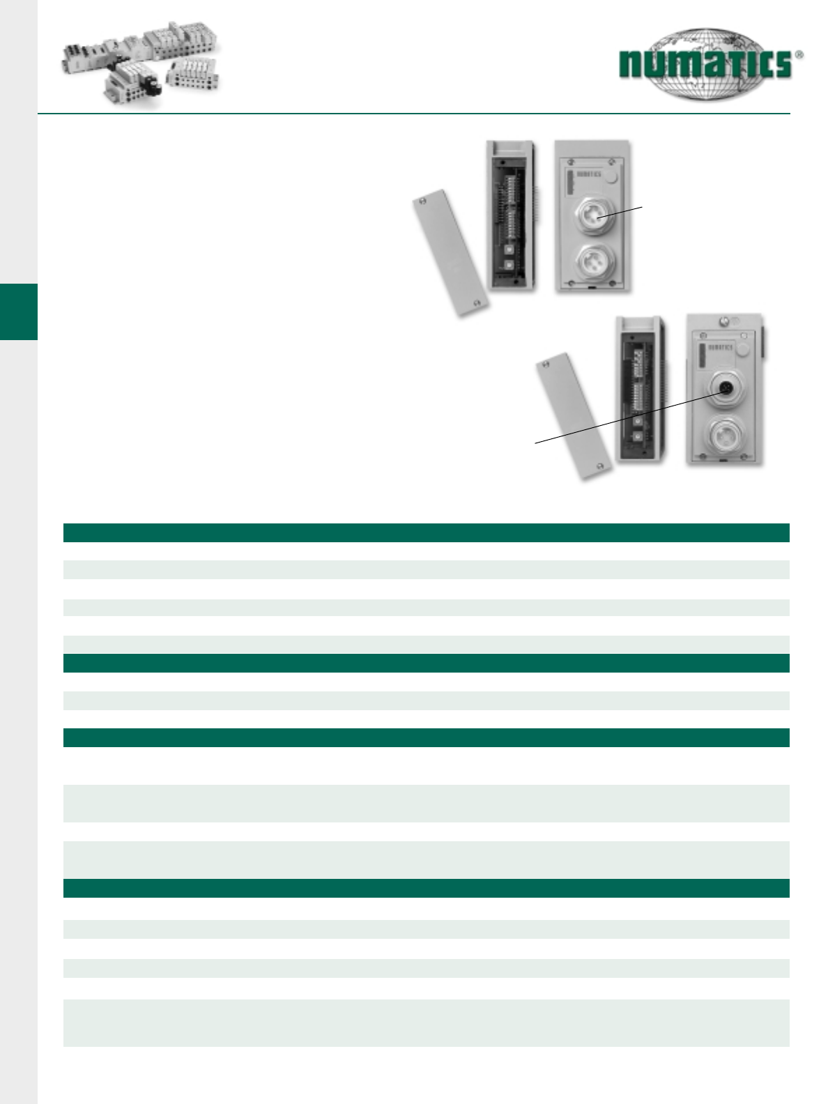
DeviceNet
DeviceNet is an open protocol bus communica-
tion system developed by Allen-Bradley based
on Controller Area Network (CAN) technology.
The governing body for DeviceNet is the Open
DeviceNet Vendors Association (ODVA). The
ODVA controls the DeviceNet specification and
oversees product conformance testing.
Numatics G2-2 DeviceNet nodes are capable of
addressing up to 192 output/96 input. They have
been tested and approved for conformance by
the ODVA.
More information about DeviceNet and the
ODVA can be obtained from the following WEB
site:
Open DeviceNet Vendors Association (ODVA)
www.odva.org
Technical Data
ELECTRICAL DATA VOLTAGE CURRENT
BUS Power 11-25 VDC 0.025 amps.
Valve & Discrete I/O 24 VDC +/- 10% 8 amps. maximum
OPERATING DATA
Temperature Range -10˚ to +115˚ F (-23˚ to +46˚ C)
Humidity 95% relative humidity, non-condensing
Moisture Designed to meet NEMA 4 / IP65 requirements
Maximum Valve Solenoid Outputs 32
CONFIGURATION DATA
Communication Module Contains all communication electronics as well as short circuit protected driver circuitry
for up to 32 valve solenoids.
Manual Configuration Module (MCM) Optional module containing DIP and rotary switches for setting device configuration data.
Note: Use option “G08” in “NX” model number
NETWORK DATA
Electronic Data Sheet (EDS) file and technical manuals are available in the download section of the Numatics, Inc.
web site at: www.numatics.com/fieldbus
Maximum Discrete I/O Points Software configurable (standard): Various combinations of 192 outputs & 96 inputs
With optional manual configuration module: Various combinations of 160 outputs & 80 inputs
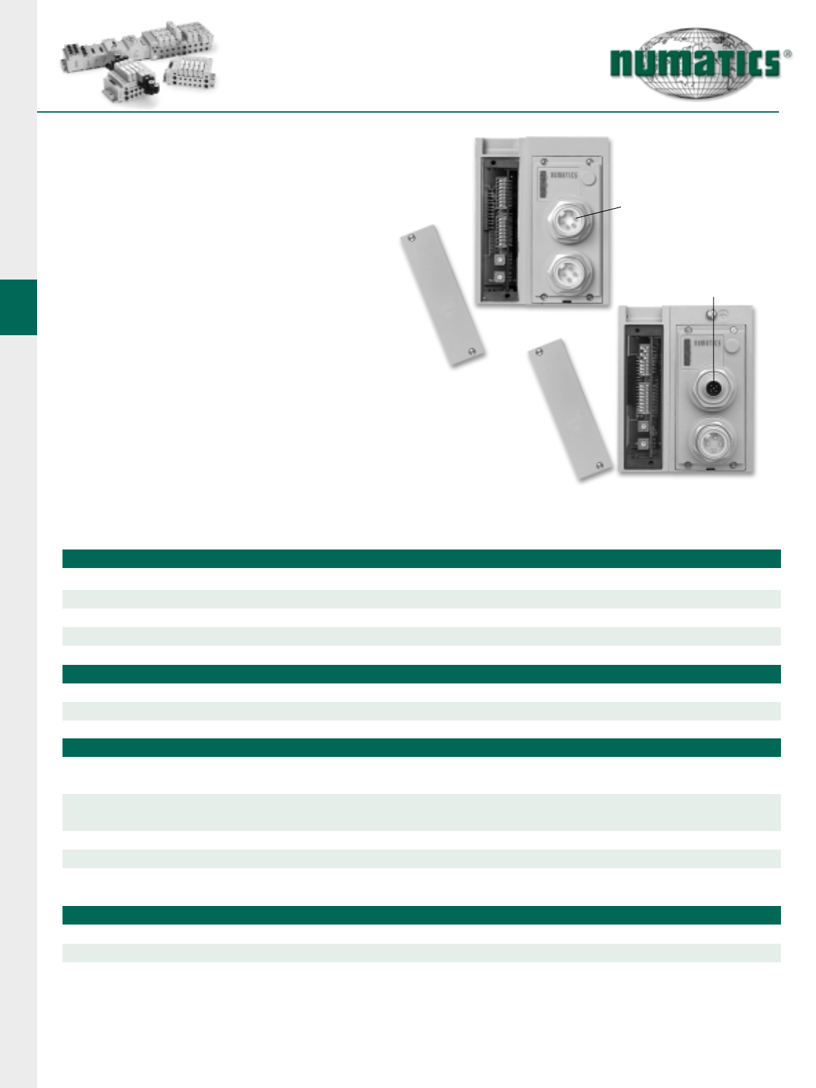
Manual
Configuration
Module
(optional)
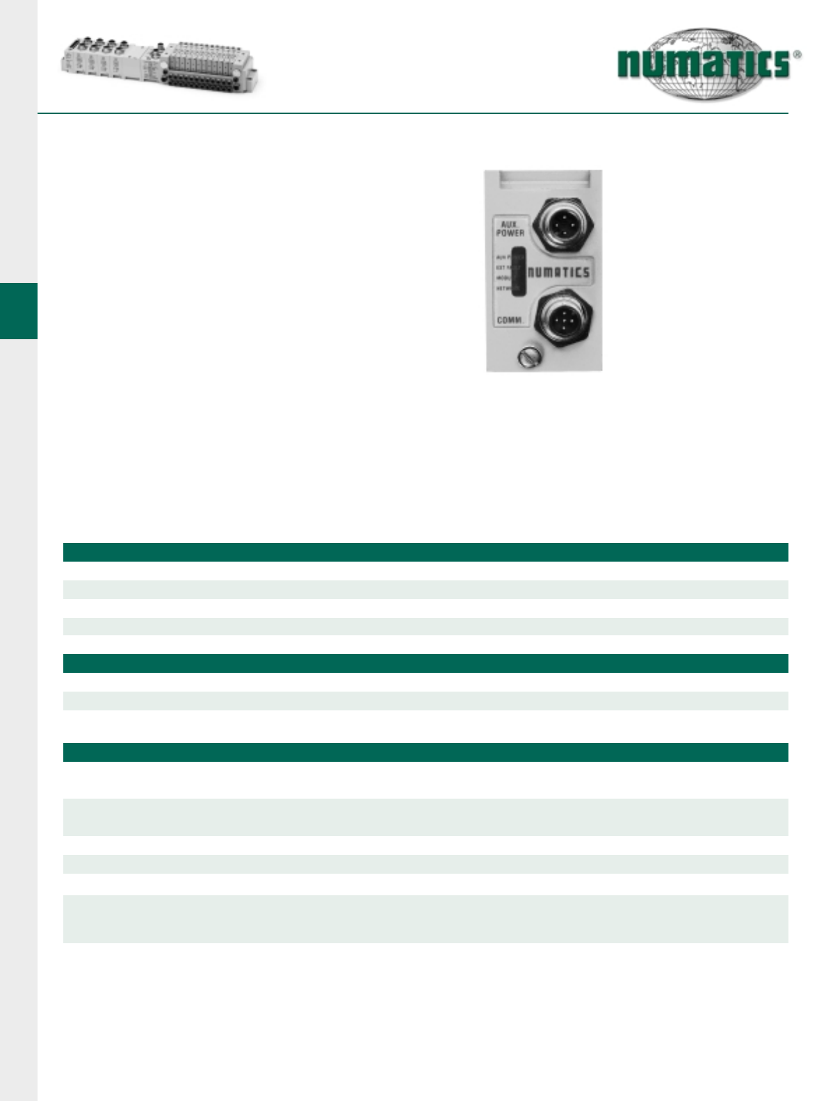
Communication
Module
Node Power 24V ± 10% 0.040 amps.
Aux Power Connector Single key way 4 pin mini type (male)
Communication Connector Single key way 5 pole (Mini or Micro type) male
LED’s Module status, network status, fuse integrity & aux power status
Supported Baud Rates 125 K Baud, 250 K Baud, 500 K Baud with Auto-Baud detection
Supported Connection Types Polled, cyclic & change of state (COS)
Bus Connector Single keyway 5 pin mini or 12mm micro types (male)
Diagnostics Shorts & open load conditions from valve solenoid coils & outputs are monitored
Special Features Supports Auto-Device Replacement (ADR)
Bus Connector
5 Pin Mini
(Standard)
Bus Connector
5 Pin 12mm Micro
(Optional consult factory)
G2-2 Electronics
15
Information subject to change without notice. For ordering information or regarding your local sales office visit www.numatics.com.
ControlNet
ControlNet is an open network that meets the
demands of today’s industrial applications requir-
ing high speed (5 MBIT/sec.), high throughput with
predictable and repeatable transfers of mission
critical data.
Originally developed by Allen-Bradley, it is based
on the Control and Information Protocol (CIP)
technology. The governing body for the ControlNet
technology is ControlNet International LTD.
More information about ControlNet can be
obtained from the following website:
www.controlnet.org
Technical Data
ELECTRICAL DATA VOLTAGE CURRENT
Valve & Discrete I/O 24 VDC +/- 10% 8 amps. maximum
OPERATING DATA
Temperature Range -10˚ to +115˚ F (-23˚ to +46˚ C)
Humidity 95% relative humidity, non-condensing
Moisture Designed to meet NEMA 4 / IP65 requirements with proper connector hoods
Maximum Valve Solenoid Outputs 32
CONFIGURATION DATA
Power Module Contains power interface electronics as well as short circuit protected driver circuitry
for up to 32 valve solenoids.
Comm. Interface Module Contains communication interface electronics and network address (MAC ID) configuration hardware.
NETWORK DATA
Electronic Data Sheet (EDS) file and technical manuals are available in the download section of the Numatics, Inc.
web site at: www.numatics.com/fieldbus
Maximum Discrete I/O Points Various combinations of 192 outputs & 96 inputs
Node Power 24V ± 10% 0.097 amps.
Aux Power Connector Single key way 4 pin mini type (male)
LED’s Module owned, module status, channel A & B, fuse integrity & aux power status
Communication Connector BNC Type
Supported Baud Rates 5 MBIT/sec
Connectors BNC type for network; RJ-45 for Network Access Point (NAP)
Diagnostics Shorts & open load conditions from valve solenoid coils & outputs are monitored
Special Features Support for redundant media via 2 BNC connectors
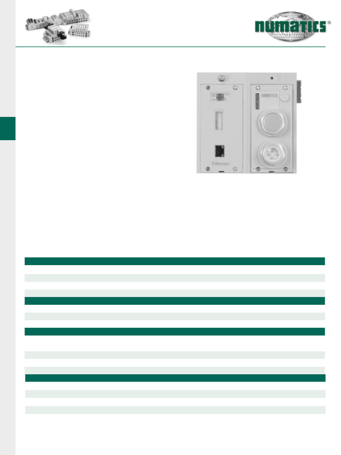
Power Module
Communications
Interface Module
G2-2 Electronics
16 Information subject to change without notice. For ordering information or regarding your local sales office visit www.numatics.com.
Technical Data
ELECTRICAL DATA VOLTAGE CURRENT
Valve & Discrete I/O 24 VDC +/- 10% 8 amps. maximum
Communication Connector Single key 5 pole (Mini or Micro type) male
LED’s Communications status, fuse integrity and aux. power status
OPERATING DATA
Temperature Range -10˚ to +115˚ F (-23˚ to +46˚ C)
Humidity 95% relative humidity, non-condensing
Moisture Designed to meet NEMA 4 / IP65 requirements
Maximum Valve Solenoid Outputs 32
CONFIGURATION DATA
Communication Module Contains all communication electronics as well as short circuit protected driver circuitry
for up to 32 valve solenoids.
Manual Configuration Module (MCM) Module containing DIP and rotary switches for setting device
configuration data.
Aux Power Connector Single keyway 4 pin mini type
Rack Size: Rack size set automatically to 1/4, 1/2, 3/4, or full rack based on
the I/O modules installed on the manifold assembly.
Maximum Discrete I/O Points Various combinations of 110 outputs & 80 inputs
Allen Bradley 1771 Remote I/O
Allen-Bradley 1771 Remote I/O is a propri-
etary protocol based on a patented chipset.
This chipset is obtained from Allen-Bradley
and incorporated into the Numatics RIO
module.
Numatics G2-2 Communications Node is
capable of addressing up to 1 full rack of I/O.
This product incorporates technology which is licensed by Allen- Bradley Company, Inc. Allen-Bradley
has not technically approved, nor does it warrant or support this product. All warranty and support for
this product and its application is provided solely by Numatics, Incorporated.
Node Power 24 VDC ± 0.065 amps.
NETWORK DATA
Supported Baud Rates 57.6 K Baud, 115.2 K Baud and 230.4 K Baud
Bus Connector Single keyway 5 pin mini or 12mm micro type
Special Features Support for processor restart/lockout and hold last state
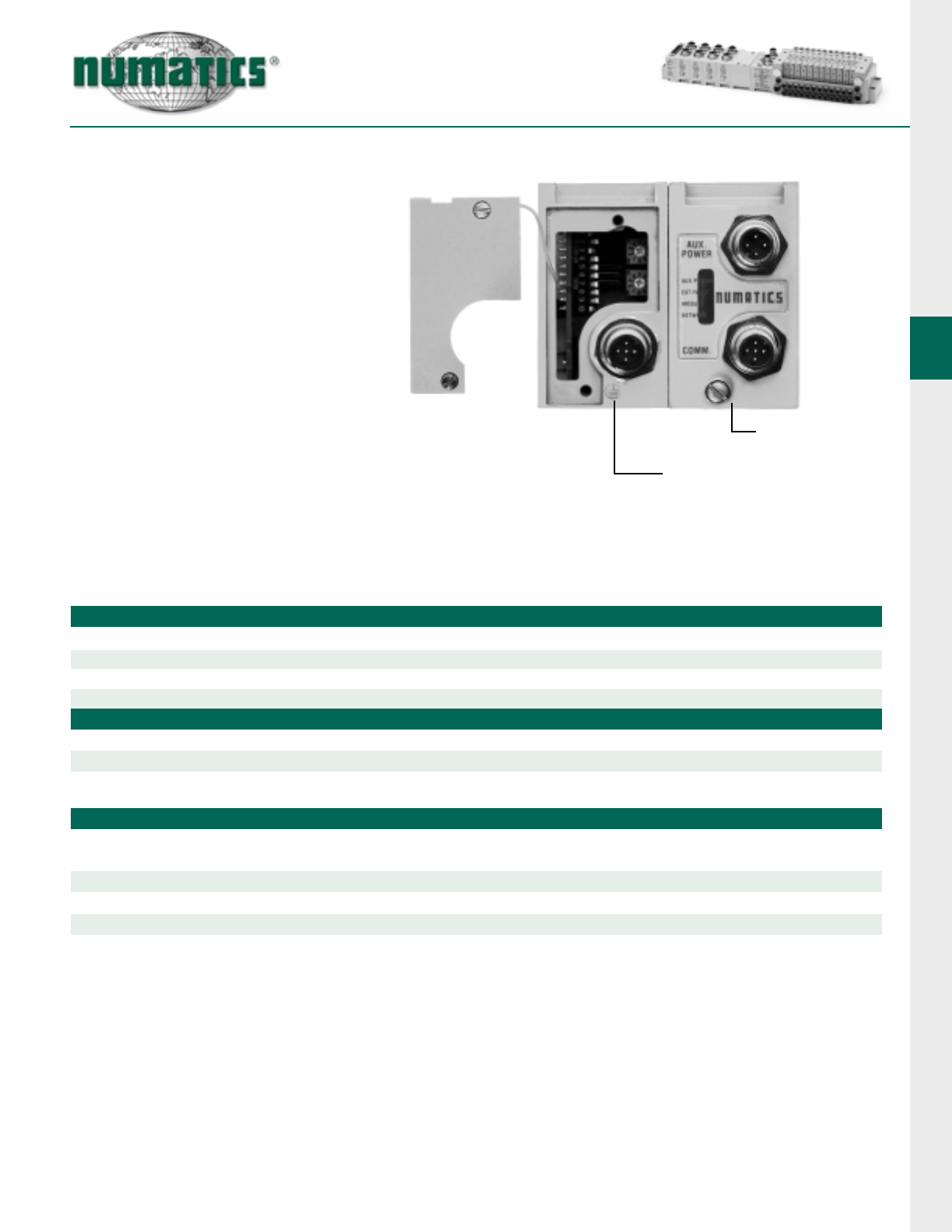
Manual
Configuration
Module
Communication
Module
Bus Connector
5 Pin Mini
(Standard)
Bus Connector
5 Pin 12mm Micro
(Optional consult factory)
G2-2 Electronics
17
Information subject to change without notice. For ordering information or regarding your local sales office visit www.numatics.com.
DeviceLogix
DeviceLogix is a Rockwell Automation technology that allows a
DeviceNet node to be programmed to execute a sequence independ-
ently from the control for the main PLC/IPC. A DeviceLogix enabled
DeviceNet node can be used in conjunction with a standard DeviceNet
network, providing simple distributed control functionality. Additionally, it
can also be used in a standalone application, without a network con-
nection, to sequence pneumatic valves and control I/O. Numatics has
integrated this license technology into its DeviceNet compatible valve
manifold series, which combine the functionality of a modular
pneumatic valve system with integrated I/O.
Programming of the DeviceLogix enabled node is done using the
industry standard DeviceNet commissioning software tool RSNetworx
for DeviceNet for Rockwell Automation. The programming environment
features an easily understandable graphics environment where the
users can simply “drag and drop” logic function blocks (i.e. AND,
NAND, OR, NOR, XOR, XNOR, RS LATCHES, COUNTERS and
TIMERS) onto a page and interconnect them to develop the required
sequence. The programmed sequence is downloaded to the node via
the standard DeviceNet communication connection, thus multiple
nodes can be programmed simultaneously on the same network.
Technical Data
ELECTRICAL DATA VOLTAGE CURRENT
Valve & Discrete I/O 24 VDC +/- 10% 8 amps. maximum
LED’s Module status, network status, auxiliary power status, fuse integrity and logic enabled.
OPERATING DATA
Temperature Range -10˚ to +115˚F (-23˚ to +46˚C)
Humidity 95% relative humidity, non-condensing
Moisture Designed to meet NEMA 4 / IP65 requirements
Maximum Valve Solenoid Outputs 32
CONFIGURATION DATA
Comm. Interface Module Contains all communication and control electronics as well as short circuit protected
driver circuitry for up to 32 valve solenoids
Aux Power Connector Single key way 4 pin mini type (male)
Communication Connector Single key way 5 pole (Mini type) male
Bus Power 11-25 VDC 0.025 amps
Maximum Discrete I/O Points Various combinations of up to 196 outputs & 96 inputs; logical limit of 72 function block
Node Power 24 VDC +/- 10%
NETWORK DATA
Supported Baud Rates 125 K Baud, 250 K Baud and 500 K Baud with auto-baud detection
Connectors Single keyway 5 pin mini or 12mm micro type (male)
Diagnostics Shorts and open load conditions from valve solenoid coils and outputs are monitored
Special Features Does not require a network connection for stand-alone applications
Electronic Data Sheet (EDS) file and technical manuals are available in the download section of the Numatics, Inc.
web site at: www.numatics.com/fieldbus
G2-2 Electronics
18 Information subject to change without notice. For ordering information or regarding your local sales office visit www.numatics.com.
Ethernet
Ethernet, used throughout the world to network
millions of PC’s has now evolved into a viable
industrial network. Ethernet is an open architec-
ture high-level communication network that
meets the demands of today’s industrial
applications requiring high-speed (10/100 Mbit/s),
high-throughput and flexibility. Various application
layers for this protocol include TCP/IP,
EtherNet/IP, and Modbus TCP/IP. Additionally,
Ethernet technology can integrate an on-board
Web Server, which can make the node readily
accessible to any standard Web browser for
configuration, testing and even retrieval of techni-
cal documentation. E-mail capability allows the
manifold to send e-mails that are triggered from
specific events ranging from diagnostic informa-
tion to automatic Preventative Maintenance
scheduling. Numatics has integrated this technol-
ogy into the G2-2 series of fieldbus manifolds,
which combines the functionality of a scalable
modular I/O system with a modular pneumatic
valve manifold.
Technical Data
ELECTRICAL DATA VOLTAGE CURRENT
Valve & Discrete I/O 24 VDC +/- 10%
LED’s Module status, link, active, net status, auxiliary power status and fuse integrity
OPERATING DATA
Temperature Range -10˚ to +115˚F (-23˚ to +46˚C)
Humidity 95% relative humidity, non-condensing
Moisture Designed to meet NEMA 4 / IP65 requirements
Maximum Valve Solenoid Outputs 32
CONFIGURATION DATA
Comm. Interface Module Contains all communication interfaced electronics
Power Module Contains all power interface electronics as well as short circuit protected
driver circuitry for up to 32 valve solenoids
Aux Power Connector Single keyway 4 pin mini type (male)
Maximum Discrete I/O Points Various combinations of up to 192 outputs & 96 inputs
Node Power 24 VDC +/- 10%
NETWORK DATA
Supported Baud Rates 10 Mbit / 100 Mbit
Connectors RJ45 or 8 Pin 12 mm
Diagnostics Shorts and open load conditions from valve solenoid coils and outputs are monitored
Special Features Integrated web server and e-mail capabilities
G2-2 Electronics
19
Information subject to change without notice. For ordering information or regarding your local sales office visit www.numatics.com.
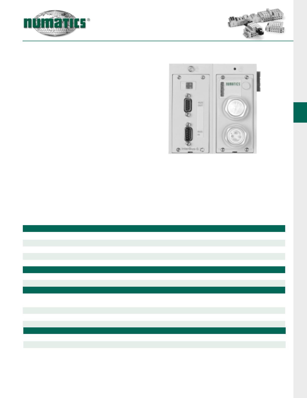
Interbus - S
Interbus-S is an open architecture, high per-
forming, ring based fieldbus system used in
many of today’s industrial network applica-
tions. I/O data is transmitted in frames that
provide simultaneous and predictable
updates to all devices on the network.
More Information about Interbus-S can be
obtained at the following Interbus-S Club
web site: www.ibsclub.com.
Technical Data
ELECTRICAL DATA VOLTAGE CURRENT
Valve & Discrete I/O 24 VDC +/- 10%
LED’s TR, CC, RBDA, BA, auxiliary power status and fuse integrity
OPERATING DATA
Temperature Range -10˚ to +115˚ F (-23˚ to +46˚ C)
Humidity 95% relative humidity, non-condensing
Maximum Valve Solenoid Outputs 32
CONFIGURATION DATA
Comm. Interface Module Contains all communication interfaced electronics
Power Module Contains all power interface electronics as well as short circuit protected
driver circuitry for up to 32 valve solenoids
Aux Power Connector Single keyway 4 pin mini type (male)
Communication Connector 9 pin Sub-D, in and out
Maximum Discrete I/O Points Various combinations of up to 160 outputs & 96 inputs
Node Power 24 VDC +/- 10%
NETWORK DATA
Supported Baud Rates 500 Kbit/s & 2 Mbit/s
Connectors Two 9 pin sub-d (1 male and 1 female)
Diagnostics Shorts and open load conditions from valve solenoid coils and outputs are monitored
G2-2 Electronics
20 Information subject to change without notice. For ordering information or regarding your local sales office visit www.numatics.com.
Technical Data
ELECTRICAL DATA VOLTAGE CURRENT
Valve & Discrete I/O 24 VDC +/- 10% 8 amps. maximum
LED’s Processor status, network status, fuse integrity & aux power status
OPERATING DATA
Temperature Range -10˚ to +115˚ F (-23˚ to +46˚ C)
Humidity 95% relative humidity, non-condensing
Moisture Designed to meet NEMA 4 / IP65 requirements
Maximum Valve Solenoid Outputs 32
CONFIGURATION DATA
Communication Module Contains all communication electronics as well as short circuit protected driver circuitry
for up to 32 valve solenoids.
Manual Configuration Module (MCM) Module containing DIP and rotary switches for setting device configuration data. To order without MCM,
use option G20 in NX model number. Optional only when using a Class 2 Profibus DP Master. (Note: see
electronic interface options page 27)
Aux. Power Connectors 1.5 MBps Single key way 4 pole 12 mm (Micro) connector
12 MBps Single key way 4 pole 12 mm (Micro) connector
Communication Connector 1.5 MBps 5 pole 12 mm (Micro) connector
12 MBps 5 pole reverse key female (Micro) connector
Maximum Discrete I/O Points Manual configurable with MCM (standard): Various combinations of 160 outputs & 96 Inputs
Software configurable (optional): Various combination of 192 outputs and 96 inputs
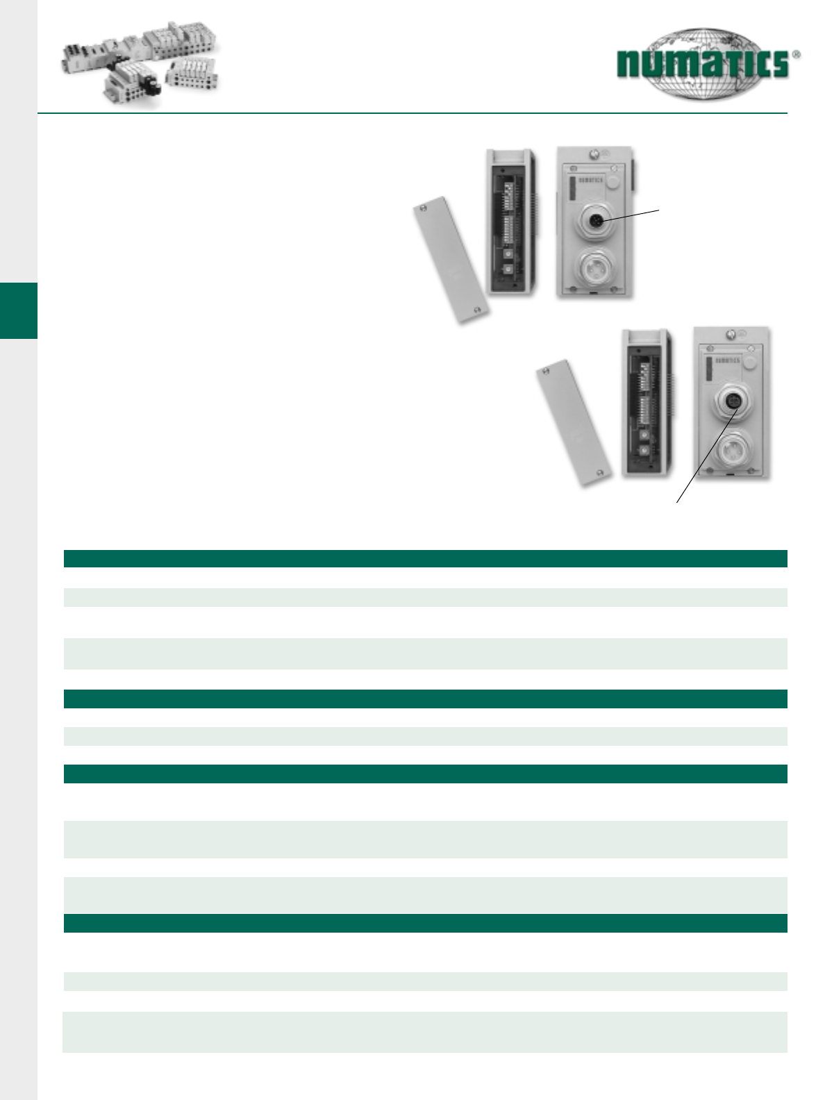
Profibus DP (1.5 MBps & 12 MBps)
Profibus DP is a vendor-independent, open field-
bus protocol designed for communication
between automation control systems and distrib-
uted I/O at the device level.
Numatics’ G2-2 Profibus DP nodes are capable
of addressing up to 164 outputs/96 inputs. They
are designed and tested to conform to the
Profibus standard EN50170. Certification is by
the Profibus Interface Center (PIC) according to
the guidelines determined by the Profibus Trade
Organization (PTO). The certification process
ensures interoperability for all Profibus devices.
More information about Profibus DP can be
obtained at the following web site:
Profibus Trade Organization (PTO)
www.profibus.com/
Node Power 24 VDC +/- 10% 0.120 amps.
NETWORK DATA
Bus Connector 1.5 MBPS: Single keyway 5 pin 12mm micro type (male)
1.5 to 12 MBPS: Single reverse key 5 pin 12mm micro (female)
Diagnostics Shorts & open load conditions from valve solenoid coils & discrete outputs are monitored
Special Features Supports Class 2 Profibus DP Master with auto-configuration, a fail-safe device
(GSD) file and technical manuals are available in the download section of the Numatics, Inc.
web site at: www.numatics.com/fieldbus
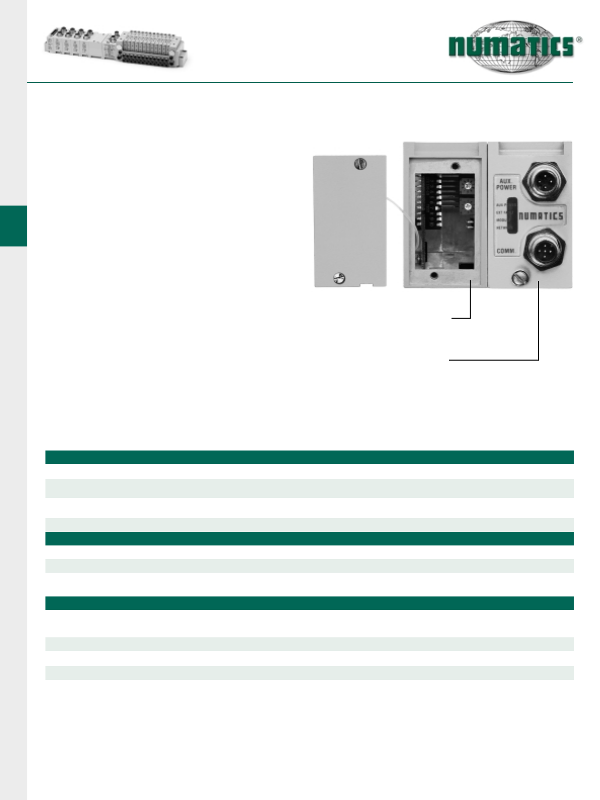
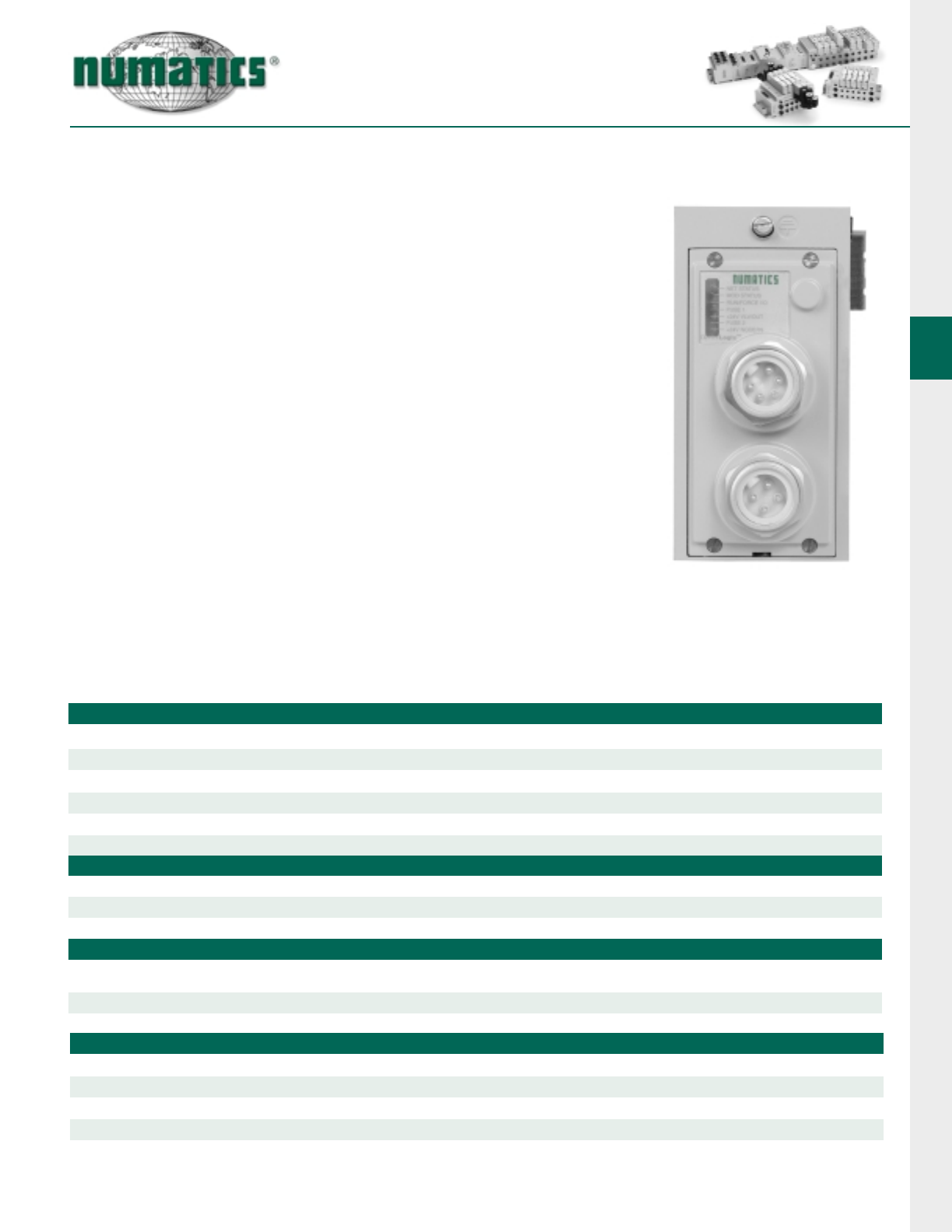
Manual
Configuration
Module
Communication
Module
Bus Connector
5 Pin 12mm Micro
Single Keyway
(1.5 MBPS)
Bus Connector, 5 Pin 12mm Micro
Reverse Keyway (12 MBPS)
G2-2 Electronics
21
Information subject to change without notice. For ordering information or regarding your local sales office visit www.numatics.com.
Technical Data
ELECTRICAL DATA
Inputs:
Voltage 24 VDC
Type NPN, PNP or contact closure
LED Indicator Input status
Outputs:
Voltage 24 VDC +/- 10%
Current 0.5 amperes per output with short circuit protection
(consult factory for higher current requirements)
Type Sinking (NPN) & Sourcing (PNP)
LED Indicator Output status
OPERATING DATA
Temperature Range -10˚ to +115˚ F (-23˚ to +46˚ C)
Humidity 95% relative humidity, non-condensing
Moisture Designed to meet NEMA 4 / IP65 requirements
Connectors Single key way 4 pin female 12mm micro and 25 & 15 pin Sub-D connectors
CONFIGURATION DATA
The physical limitation of the discrete I/O section is 6 modules including the manual configuration module.
Connectors per Block
I/O Points per Connector
Total I/O points
The maximum number of modules connected to the discrete I/O side is 6. A fully configured manifold assembly would require 6 Wide Profile Modules with double
capacity per connector (i.e. 16 I/O points per module times 6 modules equals 96 I/O points). If a Manual Configuration Module is used (standard with A-B 1771 RIO
& Profibus-DP), a maximum of five I/O modules may be installed and the maximum number of discrete I/O points is 80.
NARROW HOUSING WIDE HOUSING
44128812
1 2 16 8 1 2 22 16
4 8 16 16 8 16 22 32
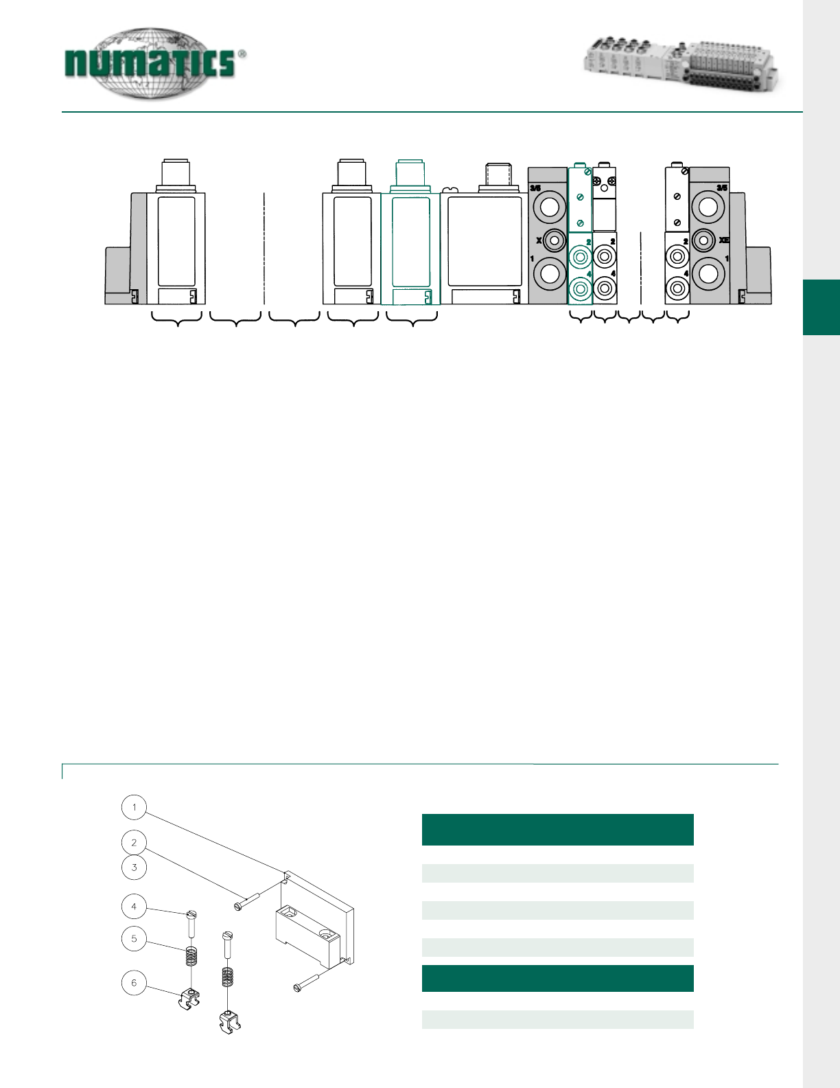
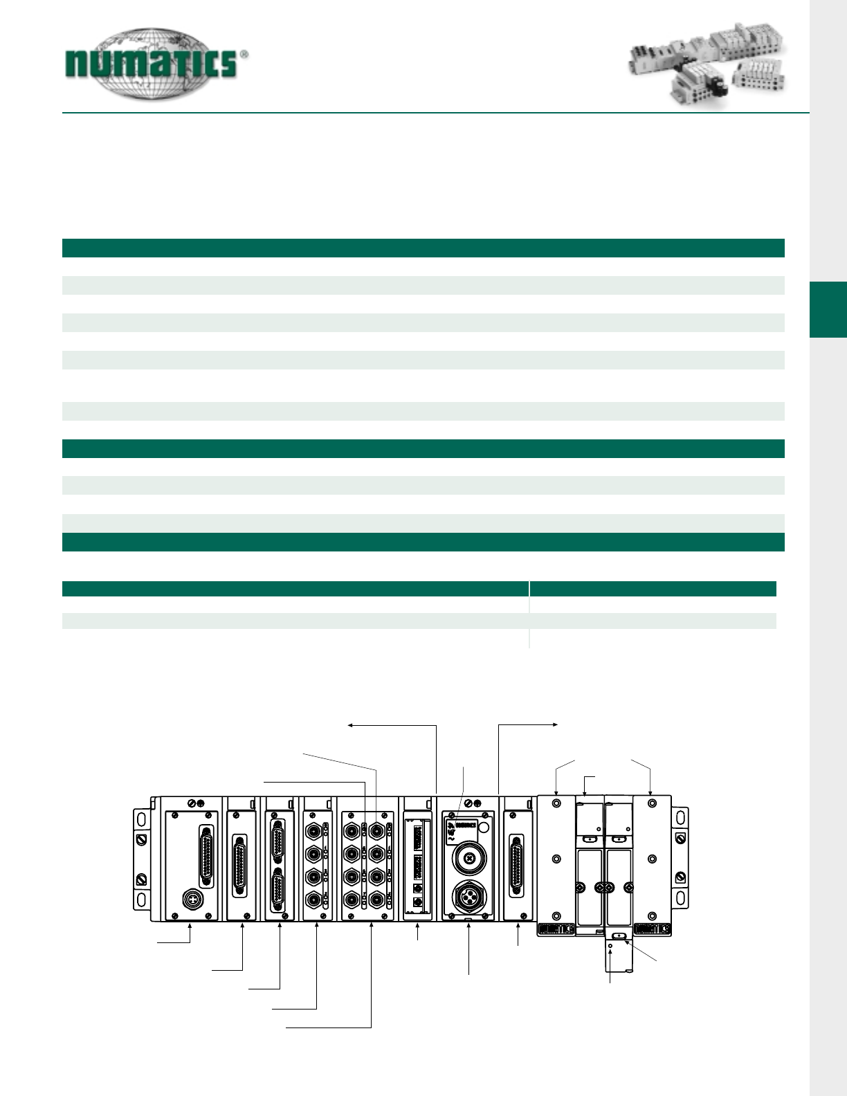
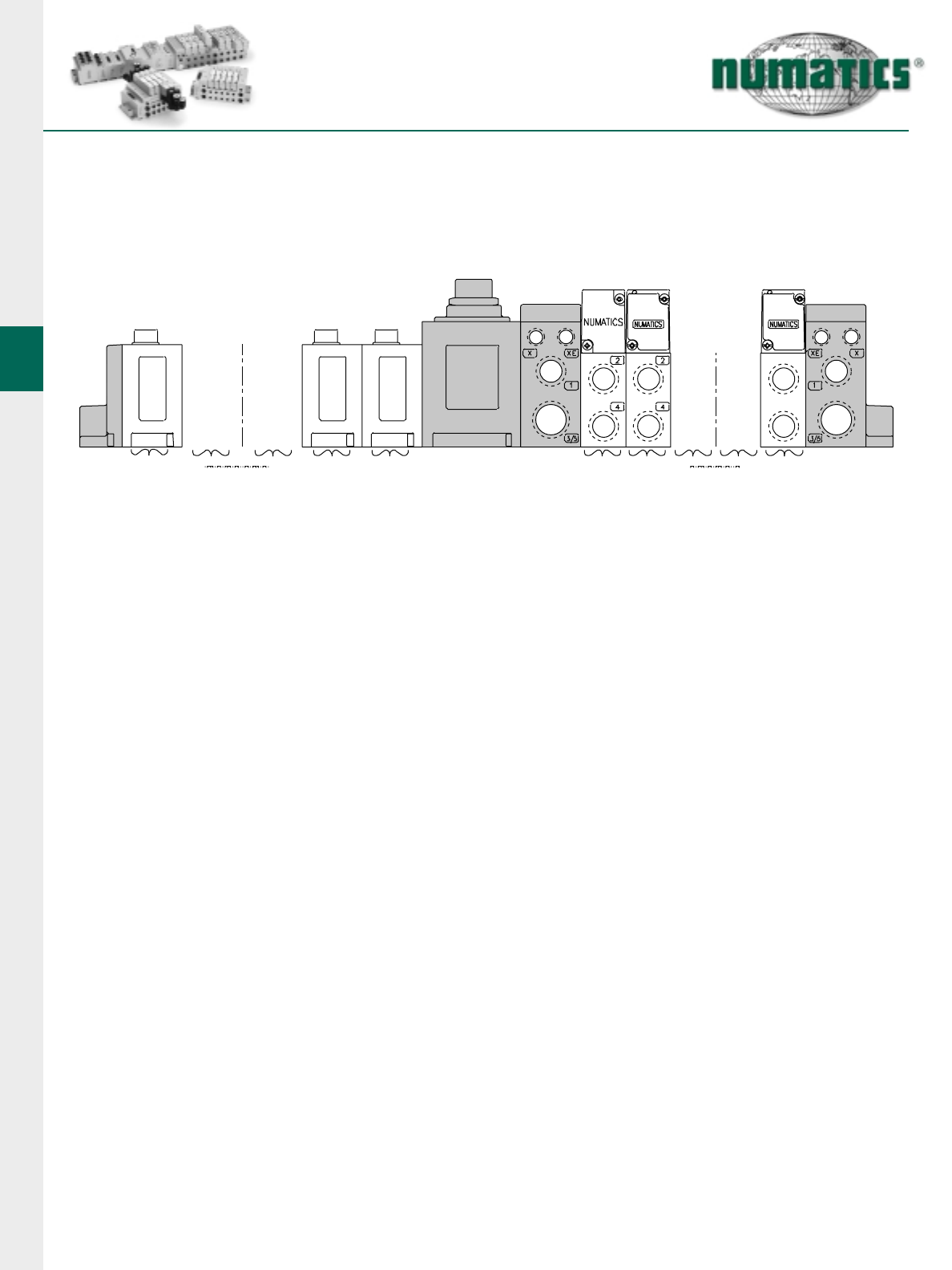
Discrete I/O Modules
Discrete I/O modules are used to connect additional I/O devices to the valve manifold node. This provides
for more efficient use of system resources when configuring a communication system.
VALVE
VALVE
END PLATES
VALVE SIDE
(maximum of 32 Solenoids)
MODULE
STATUS LED
DISCRETE I/O SIDE
(maximum of 6 Modules)
DISCRETE I/O
CONNECTORS
I/O POINT LED
STATUS INDICATOR(S)
25 PIN SUB-D
w/ LOCAL
AUX POWER
25 PIN SUB-D INPUT
DUAL 15 PIN SUB-D INPUT
4 CONNECTOR I/O MODULE
8 CONNECTOR I/O MODULE
MANUAL
CONFIGURATION
MODULE (MCM)
COMMUNICATIONS
MODULE
VALVE SIDE
SUB-D
SOLENOID LED
STATUS INDICATORS
MANUAL
OVERRIDE
G2-2 Electronics
22 Information subject to change without notice. For ordering information or regarding your local sales office visit www.numatics.com.
*Maximum number of valve stations is determined by the combination of sin-
gle and double Z-Boards types installed in the manifold sub-bases. All G2-2
communication modules support 32 output drivers for valve solenoid coils.
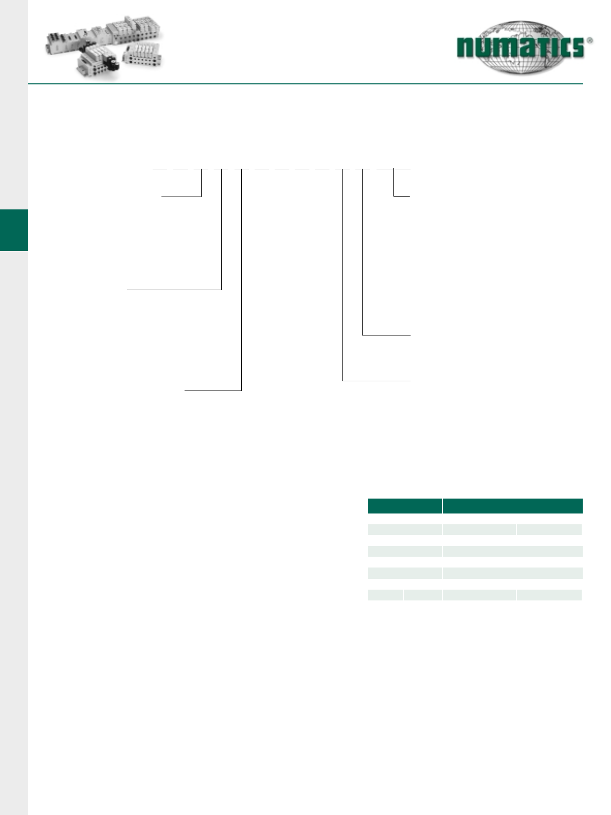
How to Order
1) Assembly Kit Selection
Each valve station must specify valve type and configuration.
E
Electrical / Electronic
Type & Location
C = Communication Module
2005 & 2012 Series
or ISO 15407-2
E = Communication Module
ISO 1, 2 & 3 Series
V = Communication Module
Mark 8, 15 & 55 Series
Valve Series
E = 2005 or ISO 15407-2 18 mm
G = 2012or ISO 15407-2 26 mm
H = Mark 8
J = Mark 15
M = Mark 55 Compact
P = Mark 55 Fullsize
Q = ISO 5599/2 Size 1
R = ISO 5599/2 Size 2
S = ISO 5599/2 Size 3
Number of Valve Stations*
A=1
B=2
C=3
D=4
E=5
F=6
G=7
H=8
AKC 0 0
Options
STD = Standard
DRM = DIN Rail Mounting
MUF = Muffler in End Plates
DWM= DIN Rail with MUF
A06 = End plate with ports on left
end only, mounting plate
only on right end
D10 = A06 w/DIN Rail Mounting
D11 = A06 w/Muffler in End Plates
F05 = A06 w/DIN Rail with MUF
14X = External Pilot
A05 = All Stations Wired as Doubles
(AKV only)
Port Type
L = Push In (2005 or 2012 only)
N = NPTF
G = Metric
End Plate Port Size
2 = 2012
3 = Same (2012, 2005, Mark 8,
ISO 5599/2 Size 1)
4 = Used with Mark 15 or
ISO 5599/2 Size 2
5 = Used with Mark 55 Compact
6 = Used with ISO 5599/2 Size 3
7 = Used with Mark 55 Fullsize
H = 2012 (2005 or 2012)
K = Same (2005 or 2012)
00
I=9
J=10
K=11
L=12
M= 13
N=14
O= 15
P=16
Q= 17
R=18
S=19
T=20
U=21
V=22
W= 23
X=24
Y=25
Z=26
2=27
3=28
4=29
5=30
6=31
7=32
D 3 L STD
3 = 3/8
K = 10mm tube
3 = Port Type G, N, or L
Port 1 = 3/8 Port 3/5 = 1/2
2 = Port Type L Only
Port 1 = 1/4 Port 3/5 = 3/8
H = Port Type L Only
Port 1 = 8mm Port 3/5 = 12mm
K = Port Type L Only
Port 1 = 10mm Port 3/5 = 14mm
2005 2012
G2-2 Electronics
23
Information subject to change without notice. For ordering information or regarding your local sales office visit www.numatics.com.
3.) Discrete I/O Table for I/O In Excess of 99
4) Discrete I/O Station Selection (see pages 23-31).
E02DF
Fieldbus Protocols
AB = Allen Bradley RIO
CN = ControlNet
DL = DeviceLogix
DN = DeviceNet™
EN = Ethernet
IS = Interbus-S
PB = Profibus DP1.5 MBps
PT = Profibus DP12 MBps
Number of
Discrete Inputs (See chart below if in excess of 99)
Number of
Discrete Outputs (See chart below if in excess of 99)
NXG
Options
E02 = Separate power standard
(valve and I/O)
G08 = With Manual Configuration Module
(if not standard) & E02
G10 = 12mm (Micro) Connector for
Communications if Not Standard
G15 = Required for Mark 8, 15, 55 Series
G18 = Valve side Sub-D NPN ouput module
G20 = Without Manual Configuration Module
G22 = Dual 15 Pin Sub-D output module
J03 = G15 plus Manual Configuration Module
valve side
J18 = Dual 25 Pin Sub-D output module
valve side
Voltage
F = 24 VDC
I/O Type
D = Digital
A = Analog
B = Analog and Digital
0816DN
I/O
CODE NUMBER
OF I/0
A0 100
A4
A1
A2
A3
A5
A6
A7
A8
A9
101
102
103
104
105
106
107
108
109
I/O
CODE I/O
CODE I/O
CODE
NUMBER
OF I/0 NUMBER
OF I/0 NUMBER
OF I/0
B0
B1
B2
B3
B4
B5
B6
B7
B8
B9
C0
C1
C2
C3
C4
C5
C6
C7
C8
C9
D0
D1
D2
110
111
112
113
114
115
116
117
118
119
120
121
122
123
124
125
126
127
128
129
130
131
132
How to Order continued
2) Fieldbus Electronics
Valve model number with plug-in manifold base (see model selection tables for the valve type).
G2-2 Electronics
24 Information subject to change without notice. For ordering information or regarding your local sales office visit www.numatics.com.
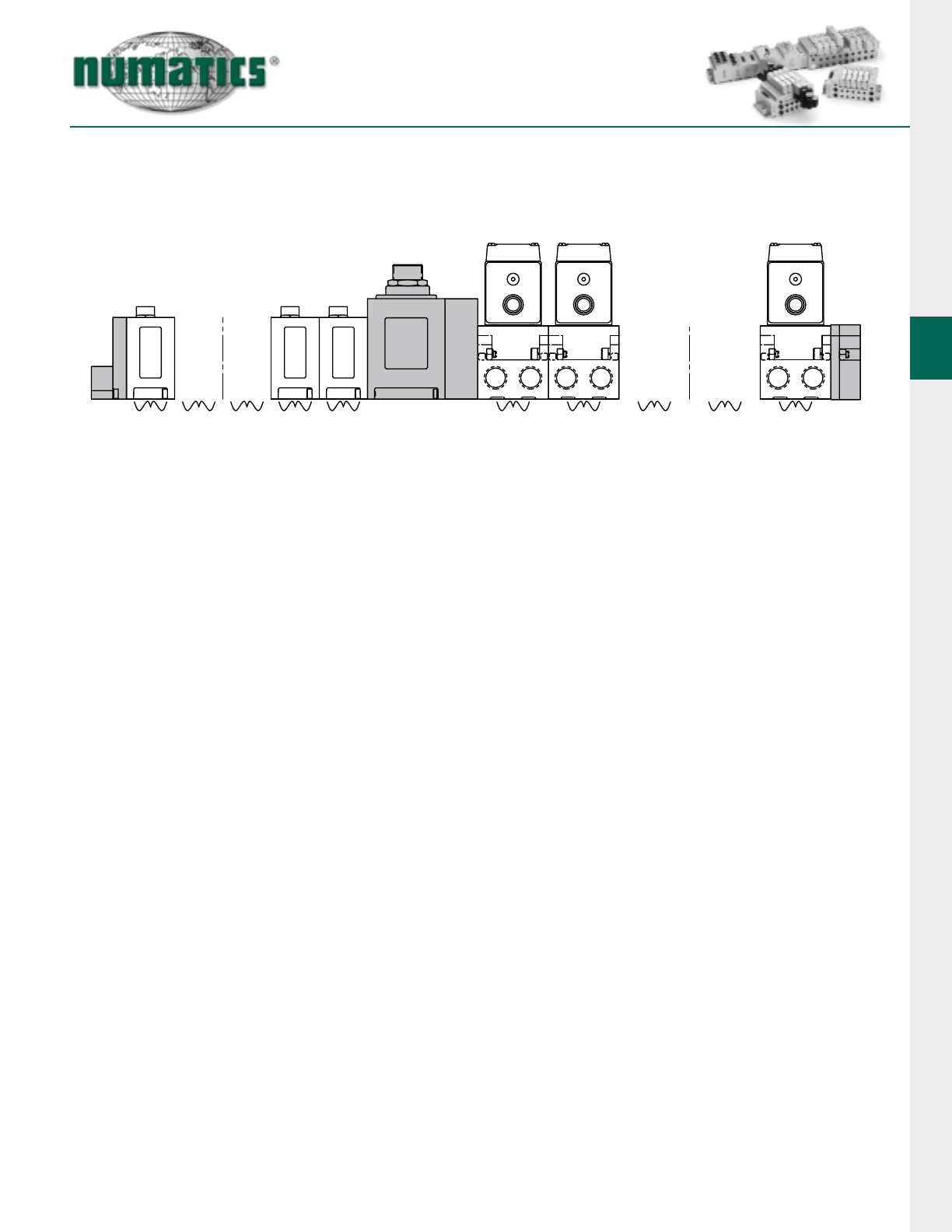
When Ordering:
AKC Manifold Assembly Kit with Fieldbus Electronics
2005 and 2012 Series and ISO 15407-2 Series
• Shaded components described by Assembly Kit (AK)
model number designation (see #1, pg. 22), with the
exception of the communication module and number of
I/O stations that are described by Electronic Interface
(NXG) model number
designation. (see #3, pg. 23)
• Each valve manifold station is listed in sequential order
form left to right when facing the port side of the
manifold as indicated.
• Each discrete I/O station is listed in sequential order
from RIGHT to LEFT starting from the communication
module as indicated.
NOTE:
1. Total of 32 solenoid outputs available. Either 32 single
solenoid valves or 16 double solenoid valves or any
combination of singles or doubles, not to exceed 32
solenoid outputs.
2. When ordering a manifold assembly that exceeds
16 solenoids, the model number of the valve station
containing the 17th solenoid MUST use a selection
for the 7th and 8th digits from the model selection table for
the valve type.
3. For manifold assemblies that exceed 16 solenoids, the
assembly MUST be configured so an even number of
solenoids are utilized prior to the station using the ribbon
cable feature. The 16th & 17th solenoid cannot be on the
same valve.
Example Order: (2005)
AKCEP00003NSTD
valve station 1 051BB4Z2MN00061
valve station 2 051BB4Z2MN00061
valve station 3 051BB4Z2MN00061
valve station 4 051BB4Z2MN00061
valve station 5 051BB4Z2MN00061
valve station 6 051BB4Z2MN00061
valve station 7 051BB4Z2MN00061
valve station 8 051BB4Z2MN00061
valve station 9 051BB4R2MN00061
valve station 10 051BB4Z2MN00061
valve station 11 051BB4Z2MN00061
valve station 12 051BB4Z2MN00061
valve station 13 051BB4Z2MN00061
valve station 14 051BB4Z2MN00061
valve station 15 051BB4Z2MN00061
valve station 16 051BB4Z2MN00061
NXGDN6438DFE02
I/O station 1 239-1317
I/O station 2 239-1317
I/O station 3 239-1319
I/O station 4 239-1467
I/O station 5 239-1480
I/O station 6 239-1460
ASSEMBLED
I/O
STATIONS 621FIELDBUS
COMMUNICATION
MODULE
NXG
VALVE
STATIONS 12 32
G2-2 Electronics
25
Information subject to change without notice. For ordering information or regarding your local sales office visit www.numatics.com.
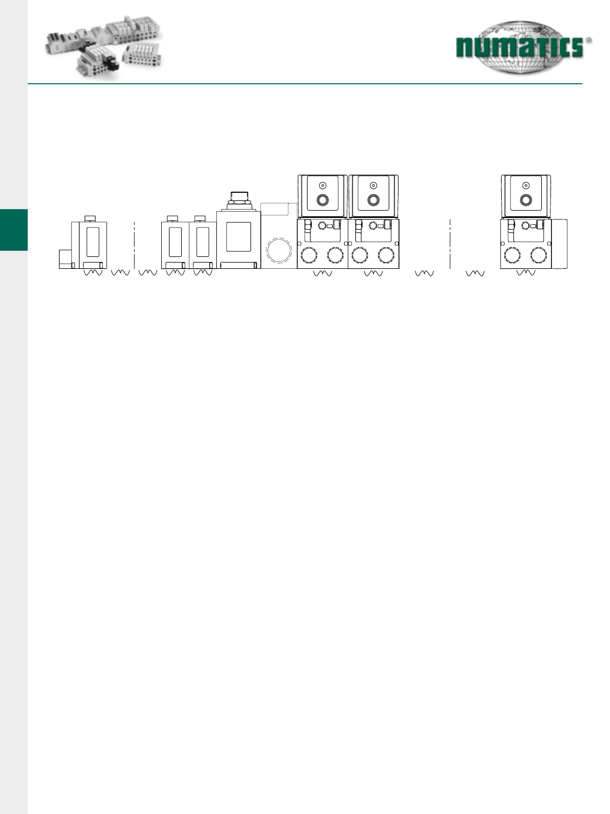
When Ordering:
AKE
ISO 5599/2 Series Manifold Assembly Kit with Fieldbus Electronics
• Shaded components described by assembly Kit (AK)
model number designation (see #1, pg. 22), with the
exception of the communication module and number of
I/O stations that are described by Electronic Interface
(NXG) model number designation. (see #3, pg. 23)
• Each valve manifold station is listed in sequential order
form left to right when facing the port side of the manifold
as indicated.
• Each discrete I/O station is listed in sequential order from
RIGHT to LEFT starting from the communication module
as indicated.
NOTE:
1.Total of 32 solenoid outputs available. Either 32 single
solenoid valves or 16 double solenoid valves or any
combination of singles or doubles, not to exceed 32
solenoid outputs.
2.When ordering a manifold assembly that exceeds 16
solenoids, the model number of the valve station
containing the 17th solenoid MUST use a selection for
the 7th and 8th digits from model selection table for the
valve type.
3.For manifold assemblies that exceed 16 solenoids, the
assembly MUST be configured so an even number of
solenoids are utilized prior to the station using the ribbon
cable feature. The 16th & 17th solenoid cannot be on the
same valve.
Example Order:
AKEQP00003NSTD
valve station 1 I13BB4Z2MN00061
valve station 2 I13BB4Z2MN00061
valve station 3 I13BB4Z2MN00061
valve station 4 I13BB4Z2MN00061
valve station 5 I13BB4Z2MN00061
valve station 6 I13BB4Z2MN00061
valve station 7 I13BB4Z2MN00061
valve station 8 I13BB4Z2MN00061
valve station 9 I13BB4R2MN00061
valve station 10 I13BB4Z2MN00061
valve station 11 I13BB4Z2MN00061
valve station 12 I13BB4Z2MN00061
valve station 13 I13BB4Z2MN00061
valve station 14 I13BB4Z2MN00061
valve station 15 I13BB4Z2MN00061
valve station 16 I13BB4Z2MN00061
NXGDN6438DFE02
I/O station 1 239-1317
I/O station 2 239-1317
I/O station 3 239-1319
I/O station 4 239-1869
I/O station 5 239-1870
I/O station 6 239-1460
ASSEMBLED
424242
I/O
STATIONS
VALVE
STATIONS
216 12 16
FIELDBUS
COMMUNICATION
MODULE
NXG
G2-2 Electronics
26 Information subject to change without notice. For ordering information or regarding your local sales office visit www.numatics.com.
When Ordering:
AKV Manifold Assembly Kit with Fieldbus Electronics
Mark 8, 15 and 55 Series
• Shaded components described by Assembly Kit
(AK) model number designation (see #1, pg. 22),
with the exception of the communication module
and number of I/O stations that are described by
Electronic Interface (NXG) model number
designation. (see #3, pg. 23)
• Each valve manifold station is listed in sequential
order form left to right when facing the port side of
the manifold as indicated.
• Each discrete I/O station is listed in sequential
order from RIGHT to LEFT starting from the com-
munication module as indicated.
NOTE:
1. Total of 32 solenoid outputs available. Either 32
single solenoid valves or 16 double solenoid valves
or any combination of singles or doubles, not to
exceed 32 solenoid outputs.
2. All valves must have a terminal block in the
mounting (19M Option).
3. Valves will be wired based on the number of
solenoids on the valve (1 output for a single
solenoid valve and 2 for double(. If all stations are
to be wired for double solenoid valves, option code
“A05”must be used in the “AK”number.
4. All blank stations will be wired for double solenoid
valves.
5. The NX number must use the “G15”option code for
combination of.
Example Order: (Mark 15)
AKVJF0004NAØ5
valve station 1 153SS415M019M61
valve station 2 153SA415M019M61
valve station 3 152SA400M000061
valve station 4 153RS115J019M00
valve station 5 153SS425M019M61
valve station 6 153SA425M019M61
valve station 7 153SS515M019M61
NXGDN3232DFG15
I/O station 1 239-1994
I/O station 2 239-1317
I/O station 3 239-1871
ASSEMBLED
P
B
CB
A
B
A
B
B
C
A
CB
FIELDBUS
COMMUNICATION
MODULE
NXG
I/O
STATIONS VALVE
STATIONS
216 12 16
Mark 55 Shown
G2-2 Electronics
27
Information subject to change without notice. For ordering information or regarding your local sales office visit www.numatics.com.
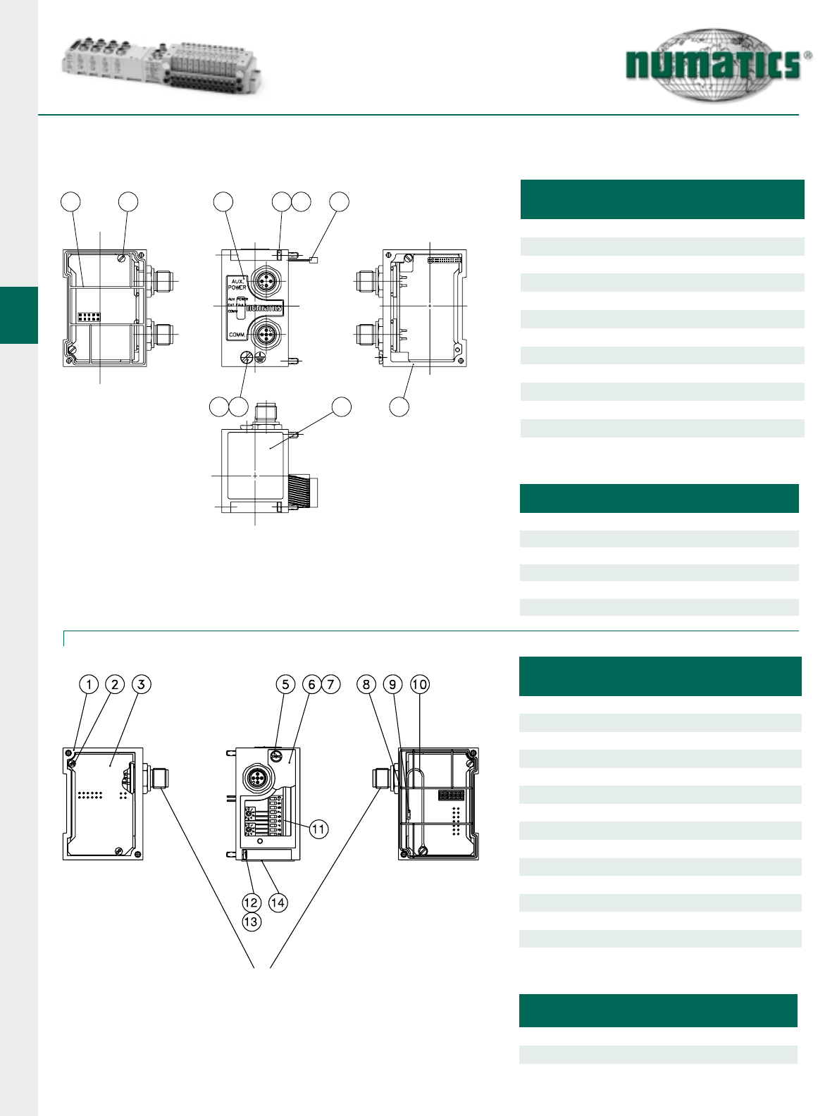
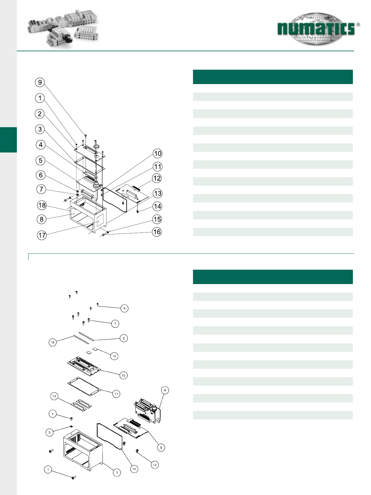
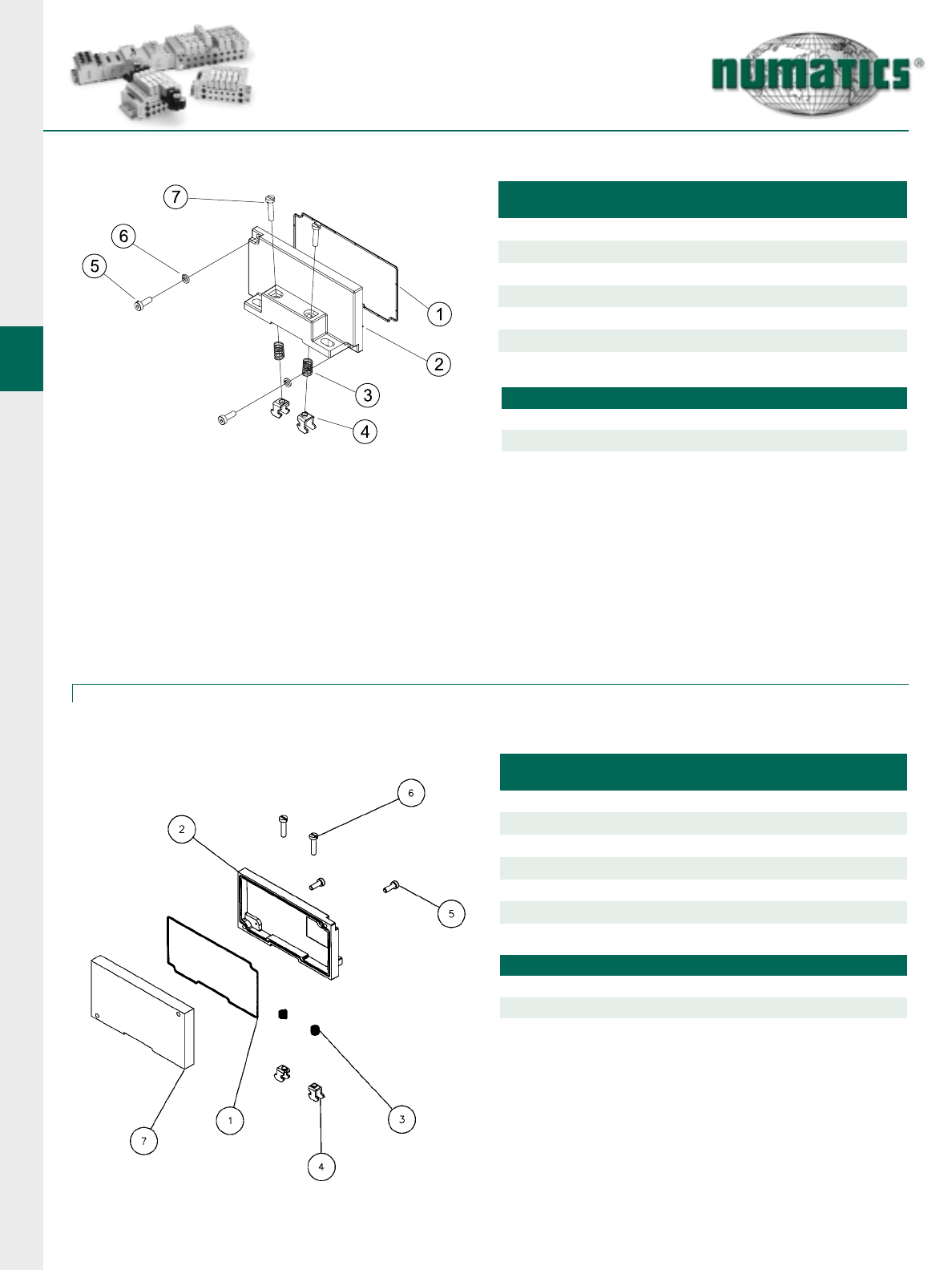
Fieldbus Communication Module and Manual Configuration Module Assemblies
Communication Module Kit
COMMUNICATION MODULE KIT
DeviceNet with Mini
Comm. Connector (Standard)
DeviceNet with 12mm
Comm. Connector
Allen-Bradley 1771 RIO with Mini
Comm. Connector (Standard)
Allen-Bradley 1771 RIO with 12mm
Comm. Connector
Profibus-DP (1.5 MBps) with 12mm
Comm. Connector
Profibus-DP (12 MBps) with Reverse
Keyway 12mm Comm. Connection
ControlNet
239-1514
239-1827
239-1516
239-1520
239-1518
PART NO.
DET.
NO. NO.
REQ’DPART NAME PART NO.
1
2
3
4
5
6
7
8
9
10
11
12
13
14
15
16
4
2
1
2
1
1
1
1
1
1
1
1
1
1
1
1
Backplane Board Ass’y (AKC, AKE)
(AKV)
Housing (not sold separately)
Screw
Cover Lens
Gasket
Cover
Comm. Board Ass’y - DeviceNet
Comm. Board Ass’y - AB1771-RIO
Comm. Board Ass’y - Profibus-DP
1.5 & 12MBps
Comm. Board Ass’y - DeviceLogix
Comm. Board Ass'y - ControlNet
Comm. Board Ass'y - EtherNet
Screw
5 Pin “Mini”Conn. - DeviceNet & AB 1771-RIO
5 Pin Conn. - Profibus DP 1.5MBps
5 Pin 12mm male - DeviceNet & AB 1771 RIO
5 Pin 12mm reverse key - Profibus DP 12MBPS
4 Pin Conn.
Ground Screw
Driver Board Ass’y
Converter Board Ass’y
Gasket
Ground Screw
Washer 128-162
127-318
113-531
256-671
256-680
127-176
140-809
140-810
140-847
140-847
140-848
127-794
DET.
NO. NO.
REQ’DPART NAME PART NO.
1
2
3
4
5
6
7
8
9
10
1
2
1
1
1
2
2
2
2
1
Housing (not sold separately)
Screw
Cover
Switch Board Assembly
Switch Backplane
Support Pin
Gasket
Screw
Lockwasher
Gasket
127-852
105-418
256-684
256-672
140-828
113-531
127-697
128-188
113-532
Manual Configuration Module (MCM) Kit 239-1384
(For All Protocols)
Interbus-S
256-666
256-716
127-852
122-1075
113-533
105-416
1
256-673
256-678
256-710
256-849
256-789
256-848
239-1519
239-2117
239-1841
1
1
Valve & Output Fuse (10A)
Node Input Fuse (4A)
140-934
140-933
DeviceLogix 239-2087
Ethernet 239-2037
AKC, AKE AKV
Consult
Factory
Consult
Factory
*
*
*
*Not used with AKV kits.
239-1461
239-1837
239-1462
239-1839
239-1463
239-1620
239-2118
239-1842
G2-2 Electronics
28 Information subject to change without notice. For ordering information or regarding your local sales office visit www.numatics.com.
I/O Block Assemblies
Input/Output Module Kit 4/8
4 INPUTS
Sinking (NPN)
Replacement I/O Board for above
Sourcing (PNP)
Replacement I/O Board for above
239-1304
4 OUTPUTS 8 INPUTS 8 OUTPUTS
256-646
239-1305
256-648
239-1306*
256-650
239-1307
256-652
239-1308
256-647
239-1309
256-649
239-1310*
256-651
239-1311
256-653
DET.
NO. NO.
REQ’DPART NAME PART NO.
1
2
3
4
5
6
7
8
9
10
1
2
2
1
1
1
1
1
2
2
1
Housing (not sold separately)
Screw
I/O Cover Assembly 4 I/O Points
I/O Cover Assembly 8 I/O Points
I/O Board Ass’y
I/O Backplane
Support Pin
Gasket
Screw
Lockwasher
Gasket
127-852
205-377
205-378
See Chart Below
256-672
140-828
113-531
127-697
128-188
113-532
Sinking (NPN)
Replacement I/O Board for above
Sourcing (PNP)
Replacement I/O Board for above
8 INPUTS 8 OUTPUTS 16 INPUTS 16 OUTPUTS
239-1312 239-1318*
256-654
239-1313
256-656
239-1314*
256-658
239-1315
256-660
239-1316
256-655
239-1317
256-657
256-659
239-1319
256-661
DET.
NO. NO.
REQ’DPART NAME PART NO.
1
2
3
4
5
6
7
8
9
10
1
2
1
1
1
1
2
1
2
2
1
Housing (not sold separately)
Screw
I/O Cover Assembly 8 I/O Points
I/O Cover Assembly 16 I/O Points
I/O Board Ass’y
I/O Backplane
Support Pin
Gasket
Screw
Lockwasher
Gasket
127-852
205-381
205-382
See Chart Below
256-665
140-828
113-531
127-697
128-188
113-533
Input/Output Module Kit 8/16
1I/O Connector Dust Cover 230-647
1I/O Connector Dust Cover 230-647
*Not to be used for new applications. Replacement units only.
G2-2 Electronics
29
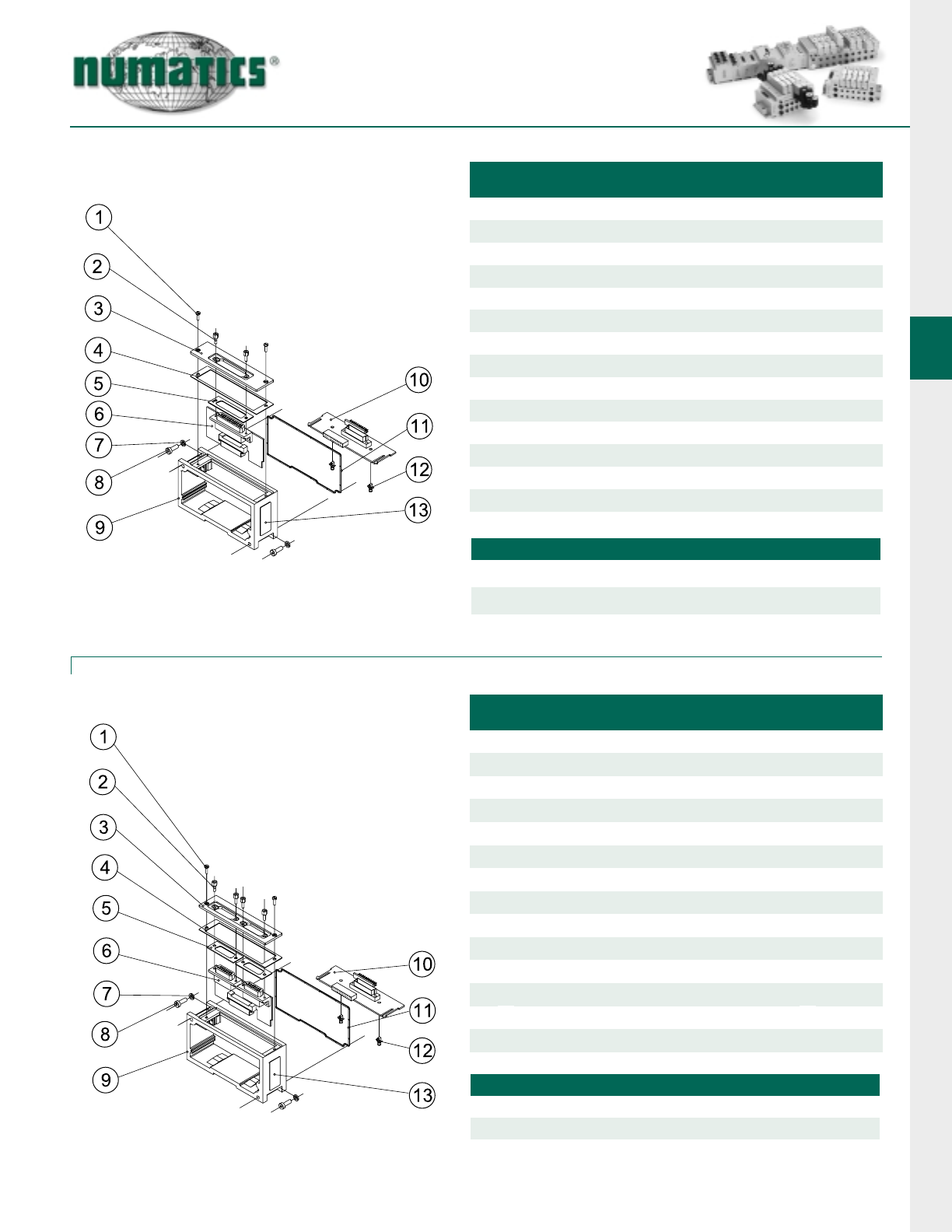
Information subject to change without notice. For ordering information or regarding your local sales office visit www.numatics.com.
DET.
NO. NO.
REQ’DPART NAME PART NO.
1
2
3
4
5
6
6
7
8
9
10
11
12
2
4
1
1
2
1
1
2
2
1
1
1
2
13 2
Screw
Hex Screw
Cover
Gasket
Gasket
Input Module Board Ass’y (Sinking NPN)
Input Module Board Ass’y (Sourcing PNP)
Lockwasher
Screw
Housing (not sold separately)
I/O Backplane Board Ass’y
Gasket
Support Pin
Nameplate
127-852
127-825
105-427
113-532
113-507
256-797
256-799
128-188
127-697
256-672
113-531
140-828
122-1057
25 PIN SUB-D INPUT KITS PART NO.
16 Point Sinking (NPN)
16 Point Sourcing (PNP)
239-1869
239-1871
DET.
NO. NO.
REQ’DPART NAME PART NO.
1
2
3
4
5
6
6
7
8
9
10
11
12
13
2
4
1
1
2
1
1
2
2
1
1
1
2
2
Screw
Hex Screw
Cover
Gasket
Gasket
Input Module Board Ass’y (Sinking NPN)
Input Module Board Ass’y (Sourcing PNP)
Lockwasher
Screw
Housing (not sold separately)
I/O Backplane Board Ass’y
Gasket
Support Pin
Nameplate
127-852
127-825
105-426
113-532
113-566
256-796
256-798
128-188
127-697
256-672
113-531
140-828
122-1057
DUAL 15 PIN SUB-D INPUT KITS PART NO.
16 Point Sinking (NPN)
16 Point Sourcing (PNP)
239-1868
239-1870
25 Pin Sub-D Connector Input
Dual 15 Pin Sub-D Connector Input
G2-2 Electronics
30 Information subject to change without notice. For ordering information or regarding your local sales office visit www.numatics.com.
25 Pin Sub-D Connector Output Module w/Aux. Power Connector 239-1460
(22 Outputs)
Dual 25 Pin Sub-D Connector Output Module 239-1994
with Aux. Power Connector
(32 Outputs)
DET.
NO. NO.
REQ’DPART NAME PART NO.
1
2
3
4
5
6
7
8
9
10
11
12
13
14
15
16
17
18
4
1
2
1
2
2
1
1
1
1
1
1
1
1
1
1
1
1
Screw
Cover
Gasket
Gasket
Output Board Ass’y
Screw
Washer
Housing (not sold separately)
Jack Screw
Washer
Screw
I/O Backplane Board Ass’y
Gasket
Support Pin
Lockwasher
Screw
Nameplate
Nameplate
127-852
105-425
113-533
113-507
256-722
127-176
128-162
127-825
128-350
127-172
256-665
113-531
140-828
128-188
127-697
122-1058
122-1057
DET.
NO. NO.
REQ’DPART NAME PART NO.
1
2
3
4
5
6
7
8
9
10
11
12
13
14
15
16
2
1
1
1
1
2
1
1
1
1
1
4
4
1
2
2
Screw
Cover Lens
Housing
Ground Screw
Cup Washer
Screw
Jack Screw
Dual Sub-D Output Board
Backplane Board Assembly
Cover
Gasket
Support Pin
Gasket
Gasket
Lens
Cover Lens
127-697
122-1153
125-802
127-176
128-162
127-852
127-825
256-825
256-665
105-448
113-533
140-828
113-507
113-531
122-1180
122-1156
2Replacement Fuse (4A) 140-933
1Replacement Fuse (4A) 140-933
G2-2 Electronics
31
Information subject to change without notice. For ordering information or regarding your local sales office visit www.numatics.com.
Valve Side Sub-D Output Modules
Dual 25 Pin Sub-D Output Module 239-1867
•Used without valves only
•Located between communication module and right mounting cover
•Provides 32 output capability 16 outputs per connector.
Single 25 Pin Sub-D Output Module 239-1713
•Used to connect auxiliary valve manifold when
main manifold utilizes 16 solenoids output or less.
•Picks up solenoid outputs 17-32.
Dual 15 Pin Sub-D Output Module 239-2041
•Use with cable on page 42 to connect with standard 25 Pin
Sub-D Manifold with 8 coils or less.
•8 outputs per connector.
DET.
NO. NO.
REQ’DPART NAME PART NO.
1
2
3
4
5
6
7
8
9
10
1
4
4
1
1
1
1
2
2
1
Cover, Dual Sub-D
Screw
Ground Screw
Cup Washer
Housing
Jack Screw
Backplane, Dual Sub-D
Connector Board
Gasket, 25 Pin Sub-D
Gasket, Cover
105-445
127-852
127-176
128-162
125-802
127-825
256-794
256-795
113-507
113-533
11
12
1
2
Gasket, Housing
Screw Assembly
113-531
127-396
DET.
NO. NO.
REQ’DPART NAME PART NO.
1
2
3
4
5
6
7
8
9
1
1
2
2
1
1
1
2
1
Housing
Cover
Screw
P.C. Board Assembly
Gasket
Jack Screw
Gasket
Screw
Gasket
125-801
105-427
127-852
256-741
113-531
127-825
113-532
127-697
113-507
DET.
NO. NO.
REQ’DPART NAME PART NO.
1
2
3
4
5
6
7
8
9
2
1
1
1
4
2
1
2
1
Screw
Housing
Cover
Jack Screw
Screw
Dual 15 Pin Sub-D Board Assembly
Gasket
Gasket
Gasket
127-697
125-801
105-426
127-825
127-852
256-847
113-532
113-566
113-531
G2-2 Electronics
32 Information subject to change without notice. For ordering information or regarding your local sales office visit www.numatics.com.
Left Mounting Cover Assembly
DET.
NO. NO.
REQ’DPART NAME PART NO.
1
2
3
4
5
6
7
1
1
2
2
2
2
2
Gasket
Mounting Cover
Spring (DIN Rail Only)
Clamp (DIN Rail Only)
Screw
Lockwasher
Screw (DIN Rail Only)
113-531
105-403
115-355
125-720
127-697
128-188
127-472
LEFT HAND MOUNTING COVER ASSEMBLY
PART NO.
Without DIN 239-1816
With DIN 239-1815
Right Mounting Cover Assembly
Use Only with Dual 25 Pin Valve Side Output Module
DET.
NO. NO.
REQ’DPART NAME PART NO.
1
2
3
4
5
6
7
1
1
2
2
2
2
1
Gasket
Mounting Cover
Spring (DIN Rail Only)
Clamp (DIN Rail Only)
Screw
Screw (DIN Rail Only)
Adaptor Plate
113-531
105-403
115-355
125-720
127-697
127-472
119-734
RIGHT HAND MOUNTING COVER ASSEMBLY
PART NO.
Without DIN 239-1873
With DIN 239-1872
G2-2 Electronics
33
Information subject to change without notice. For ordering information or regarding your local sales office visit www.numatics.com.
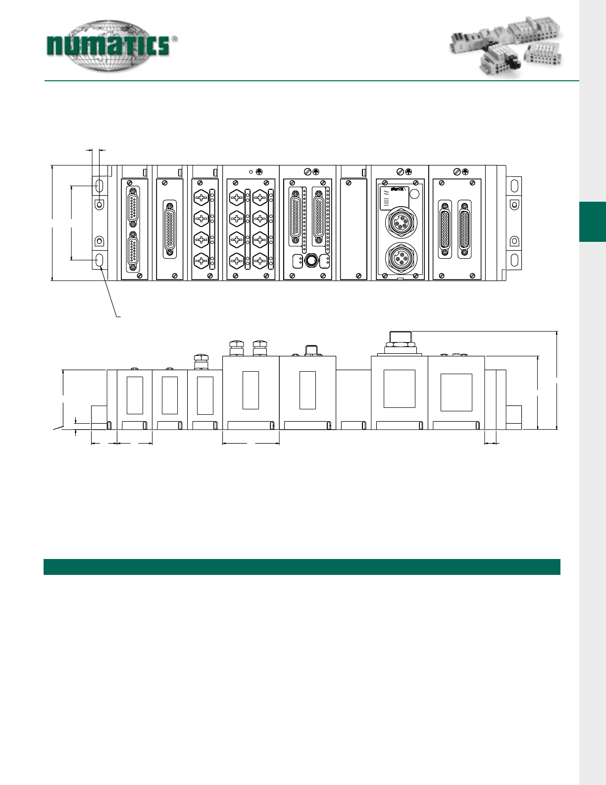
Dimensional Drawing G2-2 Fieldbus Communication Assembly
Dimensions
top dimensions = inches
bottom dimensions (in parenthesis) = millimeters
1
1
0
1
2
3
4
5
6
7
+24V NODE/IN
MOD STATUS
NET STATUS
+24V VLV/OUT
FUSE 1
FUSE 2
NetDevice
1
EX
3
OU
P
FU
EX
1
P
FU
OU
A
C
B
E
F
GHJ
M
K
L
CLEARANCE HOLE FOR
1/4 OR 6mm SCREW
8
9
10
0
1
2
11
12
13
14
15
3
4
5
6
7
A B C E F G H J K L M
0.29
(7.4) 4.65
(118.1) 2.98
(75.7) 2.40
(61.0) 1.00
(25.4) 1.00
(25.4) 1.42
(36.1) 2.28
(57.9) 0.46
(11.7) 2.95
(74.9) 3.95
(100.3)
G2-2 Electronics
34 Information subject to change without notice. For ordering information or regarding your local sales office visit www.numatics.com.
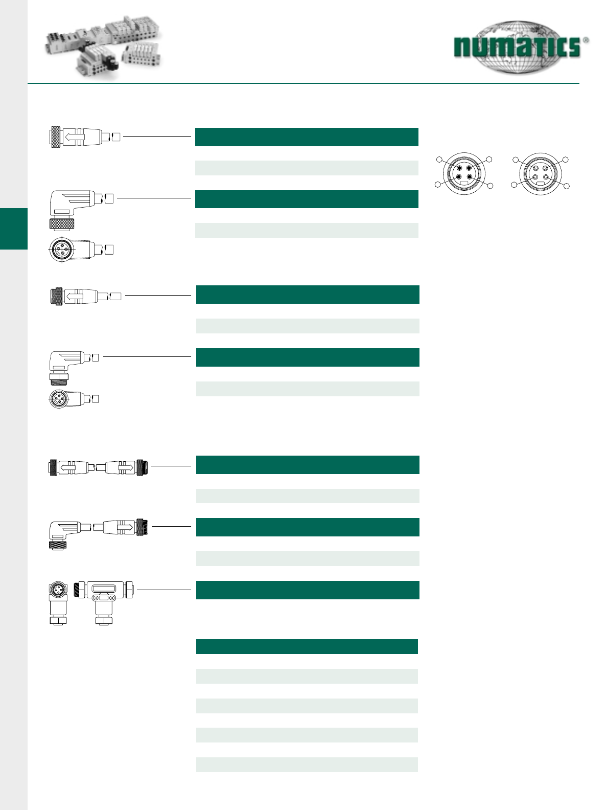
4 Pole Mini Power Cables for G2-2 Electronics
MALE 4 POLE STRAIGHT 18 AWG EURO COLOR CODE
1 Meter - MA0401MAF0000000
2 Meter - MA0402MAF0000000
5 Meter - MA0405MAF0000000
MALE 4 POLE 90°18 AWG EURO COLOR CODE
1 Meter - MB0401MAF0000000
2 Meter - MB0402MAF0000000
5 Meter - MB0405MAF0000000
F/M 4 POLE STRAIGHT 18 AWG EURO COLOR CODE
1 Meter - MC0401MAFMA04000
2 Meter - MC0402MAFMA04000
5 Meter - MC0405MAFMA04000
F 90/M STRAIGHT 18 AWG EURO COLOR CODE
1 Meter - MD0401MAFMA04000
2 Meter - MD0402MAFMA04000
5 Meter - MD0405MAFMA04000
4 POLE “T”
MC0400000MT04000
FACE VIEW FEMALE
14
23
3
4
2
1
FACE VIEW MALE
1 = Black 3 = Brown
2 = Blue 4 = White
TECHNICAL DATA
Molded Body / Insert PUR
Coupling Nut Aluminum
Cable
Voltage Rating 300 V
Amperage
Protection IP 68, NEMA 6P
Operating Temperature
PVC
5.6 A
-40°C to 90°C
Cable O.D. 0.290"
4 Pole Pin-Out
FEMALE 4 POLE STRAIGHT 18 AWG EURO COLOR CODE
1 Meter - MC0401MAF0000000
2 Meter - MC0402MAF0000000
5 Meter - MC0405MAF0000000
FEMALE 4 POLE 90°18 AWG EURO COLOR CODE
1 Meter - MD0401MAF0000000
2 Meter - MD0402MAF0000000
5 Meter - MD0405MAF0000000
G2-2 Electronics
35
Information subject to change without notice. For ordering information or regarding your local sales office visit www.numatics.com.
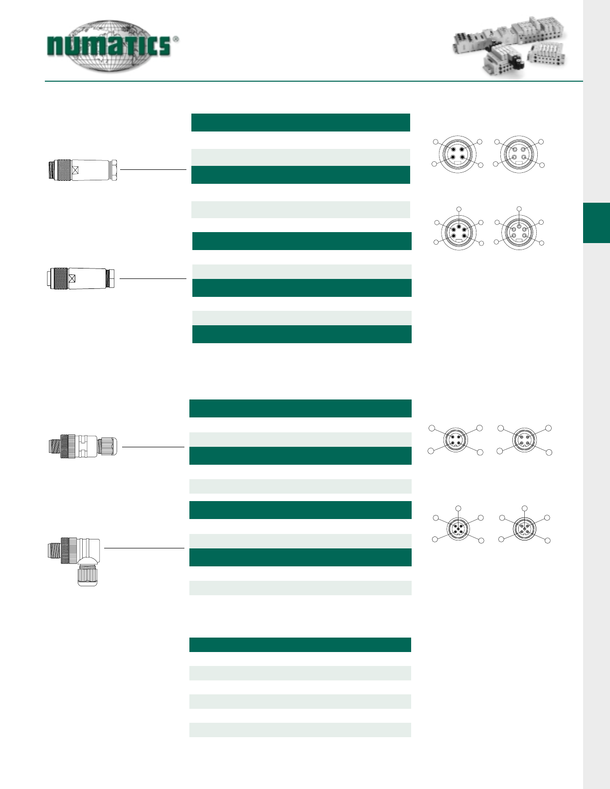
Field Attachable Connectors 3, 4, and 5 Pole
4 POLE MINI MALE STRAIGHT
PG 9 Cable Gland - MA04F20000000000
PG 13.5 Cable Gland - MA04F30000000000
PG 9 Cable Gland - MA05F20000000000
PG 13.5 Cable Gland - MA05F30000000000
4 POLE MINI FEMALE STRAIGHT
PG 9 Cable Gland - MC04F20000000000
PG 13.5 Cable Gland - MC04F30000000000
5 POLE MINI FEMALE STRAIGHT
PG 9 Cable Gland - MC05F20000000000
PG 13.5 Cable Gland - MC05F30000000000
4 POLE MICRO MALE STRAIGHT
PG 7 Cable Gland - TA04F10000000000
PG 9 Cable Gland - TA04F20000000000
5 POLE MICRO MALE STRAIGHT
PG 7 Cable Gland - TA05F10000000000
PG 9 Cable Gland - TA05F20000000000
4 POLE MICRO MALE 90 DEGREE
PG 7 Cable Gland - TB04F10000000000
PG 9 Cable Gland - TB04F20000000000
5 POLE MICRO MALE 90 DEGREE
PG 7 Cable Gland - TB05F10000000000
PG 9 Cable Gland - TB05F20000000000
FACE VIEW FEMALE
14
23
3
4
2
1
FACE VIEW MALE
FACE VIEW FEMALE
4
5
2
1
3
1
2
3
5
4
FACE VIEW MALE
FACE VIEW FEMALE
21
34
4
1
3
2
FACE VIEW MALE
FACE VIEW FEMALE
21
34
4
1
3
2
55
FACE VIEW MALE
4 Pole Pin-Out
5 Pole Pin-Out
Micro 4 Pole Pin-Out
Micro 5 Pole Pin-Out
5 POLE MINI MALE STRAIGHT
TECHNICAL DATA - Mini
Molded Body / Insert Glass Filled Nylon/Nylon
Coupling Nut Aluminum
Cable Range
Voltage Rating 600 V
Amperage
Protection IP 67, NEMA 6P
Operating Temperature
PG9: 0.157-0.315 PG13.5: 0.394-0.472
4 Pole - 9 A 5 Pole - 9 A
-40°C to 90°C
5 POLE MINI FEMALE STRAIGHT FOR RIO COMMUNICATION
PG 13.5 Cable Gland - MC05M20000000000
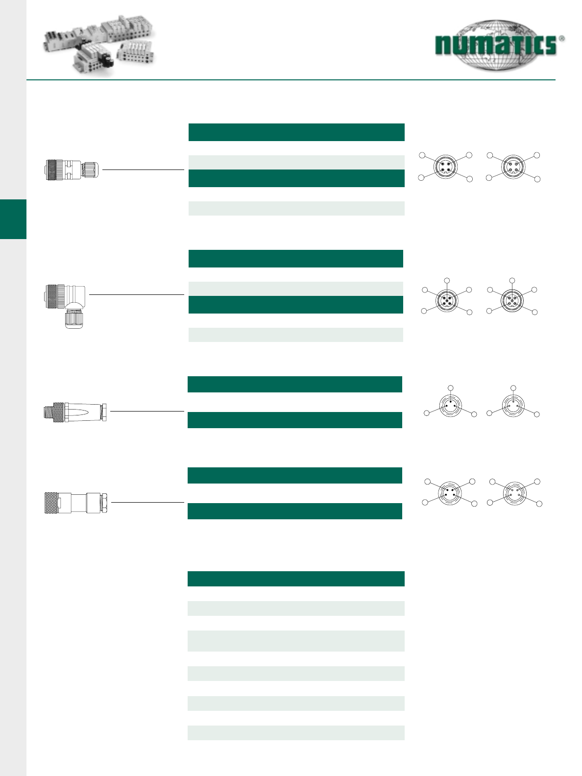
G2-2 Electronics
36 Information subject to change without notice. For ordering information or regarding your local sales office visit www.numatics.com.
FACE VIEW FEMALE
21
34
4
1
3
2
FACE VIEW MALE
FACE VIEW FEMALE
21
34
4
1
3
2
55
FACE VIEW MALE
FACE VIEW FEMALE
1
4
3
3
4
1
FACE VIEW MALE
FACE VIEW FEMALE
1
2
3
4
3
4
1
2
FACE VIEW MALE
Field Attachable Connectors 3, 4, and 5 Pole continued
4 POLE MICRO FEMALE STRAIGHT
PG 7 Cable Gland - TC04F10000000000
PG 9 Cable Gland - TC04F20000000000
5 POLE MICRO FEMALE STRAIGHT
PG 7 Cable Gland - TC05F10000000000
PG 9 Cable Gland - TC05F20000000000
4 POLE MICRO FEMALE 90 DEGREE
PG 7 Cable Gland - TD04F10000000000
PG 9 Cable Gland - TD04F20000000000
5 POLE MICRO FEMALE 90 DEGREE
PG 7 Cable Gland - TD05F10000000000
PG 9 Cable Gland - TD05F20000000000
3 POLE PICO MALE STRAIGHT
Cable Dia. 0.138 to 0.197 - PA03F00000000000
4 POLE PICO MALE STRAIGHT
Cable Dia. 0.138 to 0.197 - PA04F00000000000
3 POLE PICO FEMALE STRAIGHT
4 POLE PICO FEMALE STRAIGHT
Cable Dia. 0.138 to 0.197 - PC03F00000000000
Cable Dia. 0.138 to 0.197 - PC04F00000000000
TECHNICAL DATA - Micro 12 mm / Pico 8 mm
12 mm Molded Body Nylon
8 mm Molded Body TPU
Insert
Coupling Nut 12 mm Brass, Nickel Plated, 8 m CuZn,
brass, nickeled
Cable Range
Pico 8 mm: 0.138 - 0.197
Voltage Rating
Nylon
PG7: 0.119 - 0.255 PG9: 0.157 - 0.315
Amperage
Protection
Operating Temp -25°C to 85°C
4.0 A
12 mm: 250 V 8 mm: 60 VAC/75 VDC
IP 67, NEMA 6 (12 mm only)
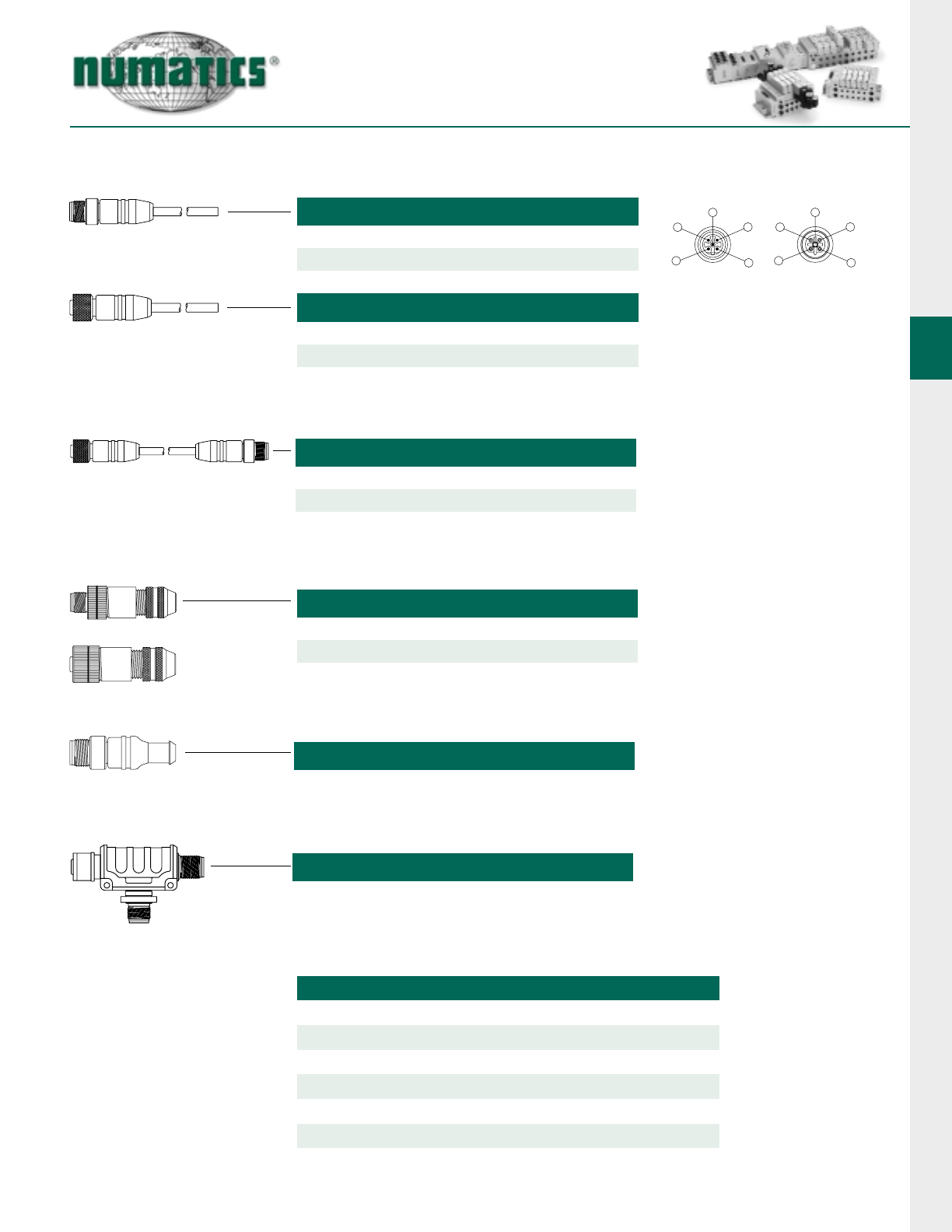
G2-2 Electronics
37
Information subject to change without notice. For ordering information or regarding your local sales office visit www.numatics.com.
MALE 12MM REVERSE KEY SINGLE ENDED
1 Meter - RA0501MHP0000000
2 Meter - RA0502MHP0000000
5 Meter - RA0505MHP0000000
FEMALE 12MM REVERSE KEY SINGLE ENDED
1 Meter - RC0501MHP0000000
2 Meter - RC0502MHP0000000
5 Meter - RC0505MHP0000000
FACE VIEW FEMALE
21
34
4
1
3
2
55
1 = N/C 2 = Green
3 = N/C 3 = Red
5 = Shield
FACE VIEW MALE
Profibus Cables and Accessories (Reverse Key)
F/M 12MM REVERSE KEY DOUBLE ENDED
1 Meter - RC0501MHPRA05000
2 Meter - RC0502MHPRA05000
5 Meter - RC0505MHPRA05000
FIELD INSTALLABLE CONNECTORS
Male - RA05F200P0000000
Female - RC05F200P0000000
MALE
FEMALE
TERMINATING RESISTORS
Male - RA050000P0000000
TECHNICAL DATA
Molded Body / Insert Cable=PUR, Field Attachable=PA
Coupling Nut
Cable
Voltage Rating
Amperage
Protection
Operating Temperature
Nickel Plated
PUR
Cable=250 V, Field Attachable=30 VAC/36 VDC
Field Attachable=4.0 A
Cable=IP67/68/NEMA 6P, Field Attachable=IP67
-40°C to 80°C Static, -5°to 80°C Moving
BUS “T”
RA050000PRT05000
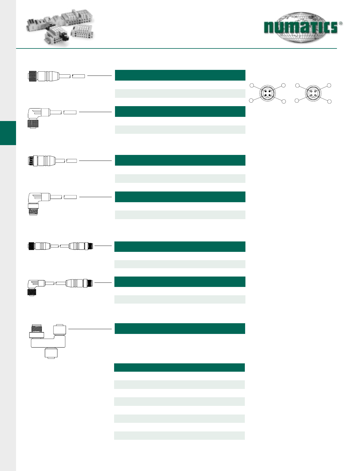
G2-2 Electronics
38 Information subject to change without notice. For ordering information or regarding your local sales office visit www.numatics.com.
4 Pole Micro Power Cables for G2-1 Electronics
BA
FACE VIEW FEMALE
21
34
4
1
3
2
FACE VIEW MALE
1 = Brown 3 = Blue
2 = White 4 = Black
FEMALE 4 POLE STRAIGHT 18 AWG EURO COLOR CODE
1 Meter - TC0401MAE0000000
2 Meter - TC0402MAE0000000
5 Meter - TC0405MAE0000000
FEMALE 4 POLE 90°18 AWG EURO COLOR CODE
1 Meter - TD0401MAE0000000
2 Meter - TD0402MAE0000000
5 Meter - TD0405MAE0000000
MALE 4 POLE STRAIGHT 18 AWG EURO COLOR CODE
1 Meter - TA0401MAE0000000
2 Meter - TA0402MAE0000000
5 Meter - TA0405MAE0000000
MALE 4 POLE 90°18 AWG EURO COLOR CODE
1 Meter - TB0401MAE0000000
2 Meter - TB0402MAE0000000
5 Meter - TB0405MAE0000000
F/M 4 POLE STRAIGHT 18 AWG EURO COLOR CODE
1 Meter - TC0401MAETA04000
2 Meter - TC0402MAETA04000
5 Meter - TC0405MAETA04000
F 90/M STRAIGHT 18 AWG EURO COLOR CODE
1 Meter - TD0401MAETA04000
2 Meter - TD0402MAETA04000
5 Meter - TD0405MAETA04000
4/5 POLE “T”(POWER)
TC0500000TT05000
Pin-Out
TECHNICAL DATA
Molded Body / Insert PUR
Coupling Nut “T”- Aluminum
Cable
Voltage Rating 250 V
Amperage
Protection IP 68, NEMA 6P
Operating Temperature
PUR
4.0 A
-40°C to 90°C
Cable O.D. 0.190"
Cables - Brass, Nickel Plated
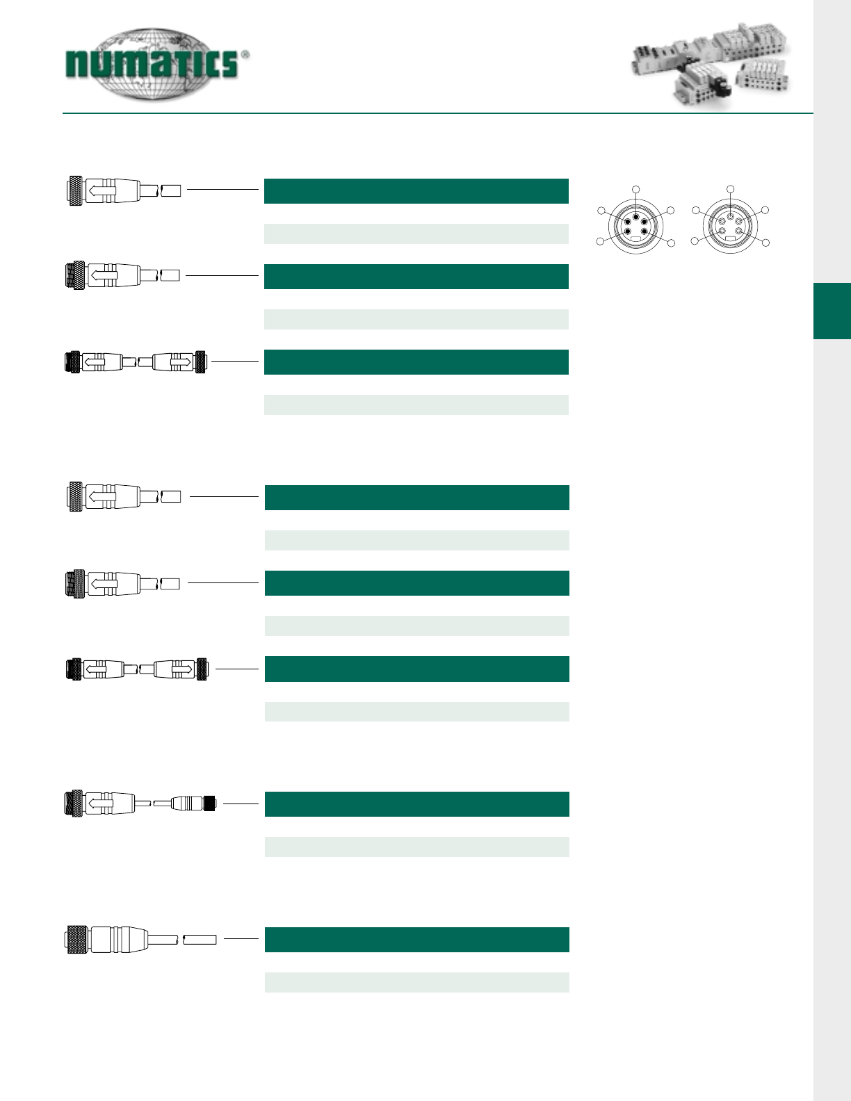
G2-2 Electronics
39
Information subject to change without notice. For ordering information or regarding your local sales office visit www.numatics.com.
FEMALE MINI THICK CABLE
3 Foot - MC0503FFD0000000
6 Foot - MC0506FFD0000000
12 Foot - MC0512FFD0000000
MALE MINI THICK CABLE
3 Foot - MA0503FFD0000000
6 Foot - MA0506FFD0000000
12 Foot - MA0512FFD0000000
FACE VIEW FEMALE
4
5
2
1
3
1
2
3
5
4
FACE VIEW MALE
1 = Shield 2 = Red
3 = Black 4 = White
5 = Blue
DeviceNet Trunk Cables, Drop Cables and Accessories
FEMALE TO MALE MINI THICK CABLE EXTENSION
3 Foot - MC0503FFDMA05000
6 Foot - MC0506FFDMA05000
12 Foot - MC0512FFDMA05000
FEMALE MINI THIN CABLE
3 Foot - MC0503FGD0000000
6 Foot - MC0506FGD0000000
12 Foot - MC0512FGD0000000
MALE MINI THIN CABLE
3 Foot - MA0503FGD0000000
6 Foot - MA0506FGD0000000
12 Foot - MA0512FGD0000000
FEMALE TO MALE MINI THIN CABLE EXTENSION
3 Foot - MC0503FGDMA05000
12 Foot - MC0512FGDMA05000
6 Foot - MC0506FGDMA05000
MALE MINI/FEMALE MICRO DROP THIN CABLE EXT.
3 Foot - MA0503FGDTC05000
6 Foot - MA0506FGDTC05000
10 Foot - MA0512FGDTC05000
FEMALE MICRO THIN CABLE
3 Foot - TC0503FGD0000000
6 Foot - TC0506FGD0000000
12 Foot - TC0512FGD0000000
Mini
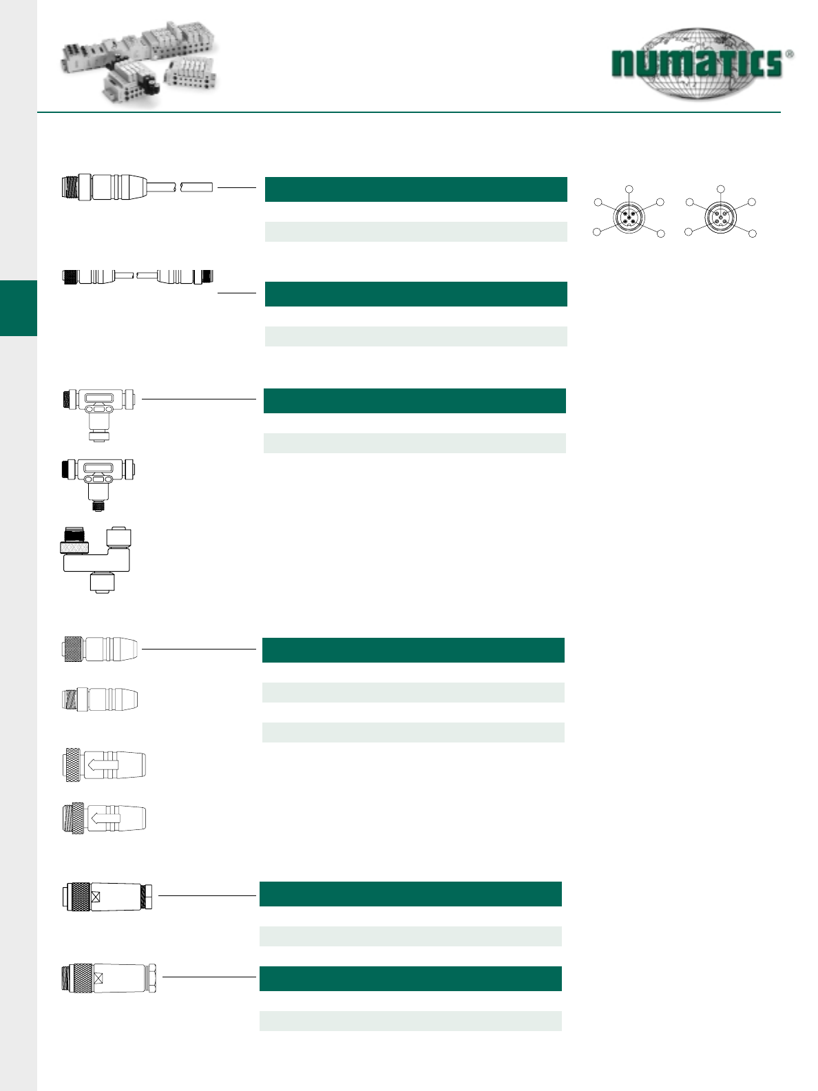
G2-2 Electronics
40 Information subject to change without notice. For ordering information or regarding your local sales office visit www.numatics.com.
MICRO FEMALE
MICRO MALE
BA
FACE VIEW FEMALE
21
34
4
1
3
2
55
FACE VIEW MALE
1 = Shield 2 = Red
3 = Black 4 = White
5 = Blue
DeviceNet Trunk Cables, Drop Cables and Accessories continued
MALE MICRO THIN CABLE
3 Foot - MC0503FFD0000000
6 Foot - MC0506FFD0000000
12 Foot - MC0512FFD0000000
FEMALE/MALE MICRO THIN CABLE EXTENSION
3 Foot - MA0503FFD0000000
6 Foot - MA0506FFD0000000
12 Foot - MA0512FFD0000000
DEVICENET T’S
3 Way Mini “T”- MC0500000MT05000
3 Way Mini - Micro “T”- TC0500000MT05000
3 Way Micro “T”- TC0500000TT05000
3 WAY MINI “T”
3 WAY MINI / MICRO “T”
3 WAY MICRO “T”
MINI FEMALE
MINI MALE
TERMINATING RESISTORS
Micro Female - TC05000000000000
Micro Male - TA05000000000000
FEMALE MINI FIELD ATTACHABLE
PG 9 Cable Gland - MC05F200D0000000
PG 13.5 Cable Gland - MC05F300D0000000
Mini Female - MC05000000000000
Mini Male - MA05000000000000
MALE MINI FIELD ATTACHABLE
PG 9 Cable Gland - MA05F200D0000000
PG 13.5 Cable Gland - MA05F300D0000000
Micro
NOTE: Color coded for DeviceNet.
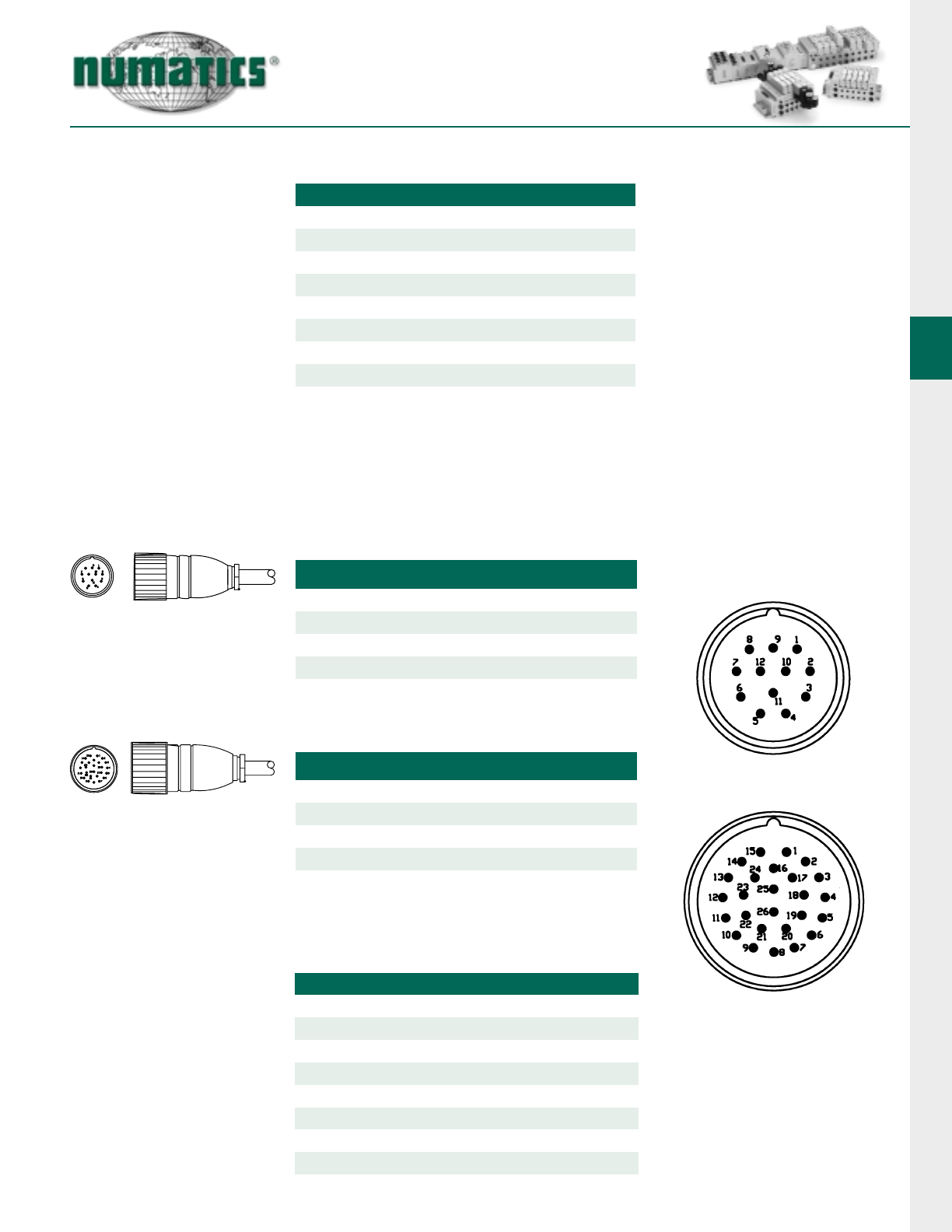
G2-2 Electronics
41
Information subject to change without notice. For ordering information or regarding your local sales office visit www.numatics.com.
DeviceNet Trunk Cables, Drop Cables and Accessories continued
12 and 26 Pole Cables and Connectors
12 POLE ROUND FEMALE CABLE 20 AWG - UNSHIELDED
Connector with Crimp Contacts - 230-879
Connector with Solder Cups - 230-960
2 Meter - CC1202MB00000000
5 Meter - CC1205MB00000000
10 Meter - CC1210MB00000000
26 POLE ROUND FEMALE CABLE 20 AWG - UNSHIELDED
Connector with Crimp Contacts - 230-742
Connector with Solder Cups - 230-1070
2 Meter - CC2602MB00000000
10 Meter - CC2610MB00000000
5 Meter - CC2605MB00000000
Pin-Out
TECHNICAL DATA
Connector Body Nickel Plated, Copper Alloy
Insert Thermoplastic
Cable
Voltage Rating 300 V
Amperage
Protection IP 67
Operating Temperature
PVC
4.0 A / Conductor
-40°C to 70°C
Cable O.D. Thick - 0.475" Thin - 0.275"
TECHNICAL DATA
Molded Body / Insert PUR
Coupling Nut Mini - Aluminum
Cable
Voltage Rating Mini - 300 V Micro - 150 V
Amperage
Protection IP 68, NEMA 6P
Operating Temperature
PVC
Thick - 8.0 A Thin - 2.4 A
-20°C to 90°C
Cable O.D. Thick - 0.475" Thin - 0.275"
Micro - Nickel Plated Brass
NOTE: Cable does not have color
identification; each conductor is
numbered the length of the cable.
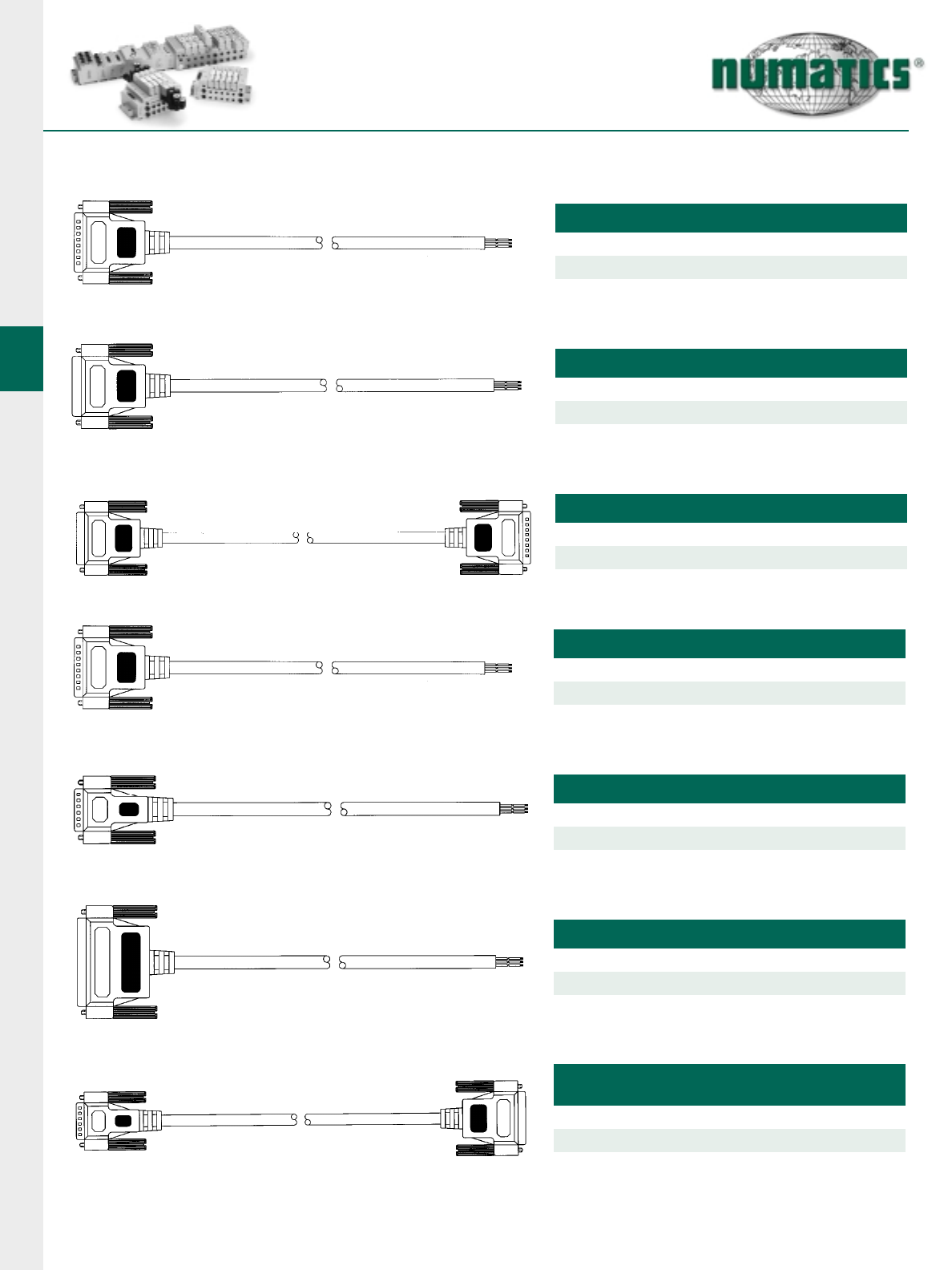
G2-2 Electronics
42 Information subject to change without notice. For ordering information or regarding your local sales office visit www.numatics.com.
Sub-D Cables
25 PIN SUB-D MALE CABLE 22 AWG - UNSHIELDED
2 Meter - SA2502MCX0000000
5 Meter - SA2505MCX0000000
10 Meter - SA2510MCX0000000
25 PIN SUB-D FEMALE CABLE 22 AWG - UNSHIELDED
2 Meter - SC2502MCX0000000
10 Meter - SC2510MCX0000000
5 Meter - SC2505MCX0000000
25 PIN SUB-D MALE/FEMALE CABLE 22 AWG - UNSHIELDED
2 Meter - SA2502MCXSC25000
5 Meter - SA2505MCXSC25000
10 Meter - SA2510MCXSC25000
25 PIN SUB-D MALE CABLE 24 AWG - SHIELDED
2 Meter - SA2502MDX0000000
5 Meter - SA2505MDX0000000
10 Meter - SA2510MDX0000000
15 PIN SUB-D MALE CABLE 24 AWG - SHIELDED
2 Meter - SA1502MDX0000000
10 Meter - SA1510MDX0000000
5 Meter - SA1505MDX0000000
37 PIN SUB-D FEMALE CABLE 22 AWG - UNSHIELDED
2 Meter - SC3702MCX0000000
10 Meter - SC3710MCX0000000
5 Meter - SC3705MCX0000000
15 PIN MALE/25 PIN FEMALE SUB-D CABLE
22 AWG - UNSHIELDED
2 Meter - SA1502MCXSC25000
5 Meter - SA1505MCXSC25000
10 Meter - SA1510MCXSC25000
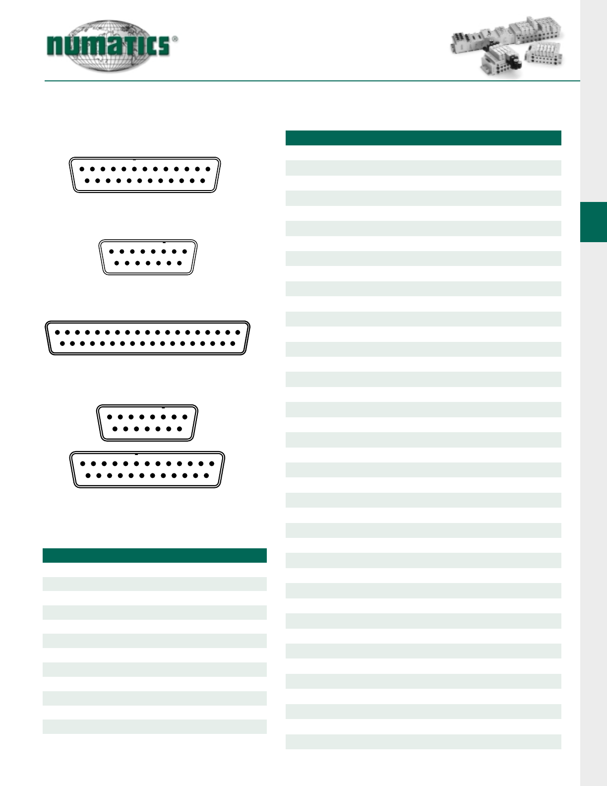
G2-2 Electronics
43
Information subject to change without notice. For ordering information or regarding your local sales office visit www.numatics.com.
Sub-D Cables continued
22
1
18
16
23
1514
5
4
17 20
7
6
19
9
8
21 24
10 11
23
13
12
25
1
13
11
23
109
5
4
12 15
7
6
14
8
23
1234
20 21 22
17
35
16
34
57
69
810 11 13
12 14
24 25 26 27 28 29 30 31 32 33
15 18 19
36 37
22
1
18
16
23
1514
5
4
17 20
7
6
19
9
8
21 24
10 11
23
13
12
25
1
13
11
23
109
5
4
12 15
7
6
14
8
CONNECTOR (CABLE)
PIN 1
PIN 2
PIN 3
PIN 5
PIN 4
CONDUCTOR
PIN 6
PIN 7
PIN 8
PIN 9
PIN 10
PIN 11
PIN 12
PIN 13
PIN 14
PIN 15
PIN 16
PIN 17
PIN 18
PIN 19
PIN 20
PIN 21
PIN 22
PIN 23
PIN 24
PIN 25
Black
White
Red
Green
Orange
Blue
White/Black
Red/Black
Green/Black
Orange/Black
Blue/Black
Black/White
Red/White
Green/White
Blue/White
Black/Red
White/Red
Orange/Red
Blue/Red
Red/Green
Orange/Green
Black/White/Red or Brown/White
White/Black/Red or Yellow/Black
Red/Black/White or Violet/White
Green/Black/White or Gray/Black
TECHNICAL DATA
Connector Body PVC
Cable PVC
Cable O.D.
Voltage Rating 300 V
Amperage
Protection NEMA 12
Operating Temperature
37 Conductor, 22 AWG - N/A
37 Conductor, 22 AWG - 2.0 A/Conductor
Max 80°C
15 Conductor, 24 AWG - 0.256"
25 Conductor, 22 AWG - 0.394"
25 Conductor, 24 AWG - 0.335"
25 Conductor, 22 AWG - 2.0 A/Conductor
25 Conductor, 24 AWG - 2.0 A/Conductor
15 Conductor, 24 AWG - 2.0 A/Conductor
25 Pin-Out
15 Pin-Out
37 Pin-Out
15 to 25 Pin-Out
Pin 26
Pin 27
Pin 28
Pin 29
Pin 30
Pin 31
Pin 32
Pin 33
Pin 34
Pin 35
Pin 36
Pin 37
Not Used
Not Used
Not Used
Orange/Black/White or Yellow
Blue/Black/White or Violet
Black/Red/Green or Gray
White/Red/Green or Pink
Red/Black/Green or Light Green
Green/Black/Orange or Orange/ White
Orange/Black/Green or Pink/Black
Blue/White/Orange or Pink/Green
Black/White/Orange or Pink/Red
White/Red/Orange or Pink/Violet
Orange/ White/Blue or Light Blue
White/Red/Blue or Light Brown
Black/White/Green
White/Black/Green
Red/White/Green
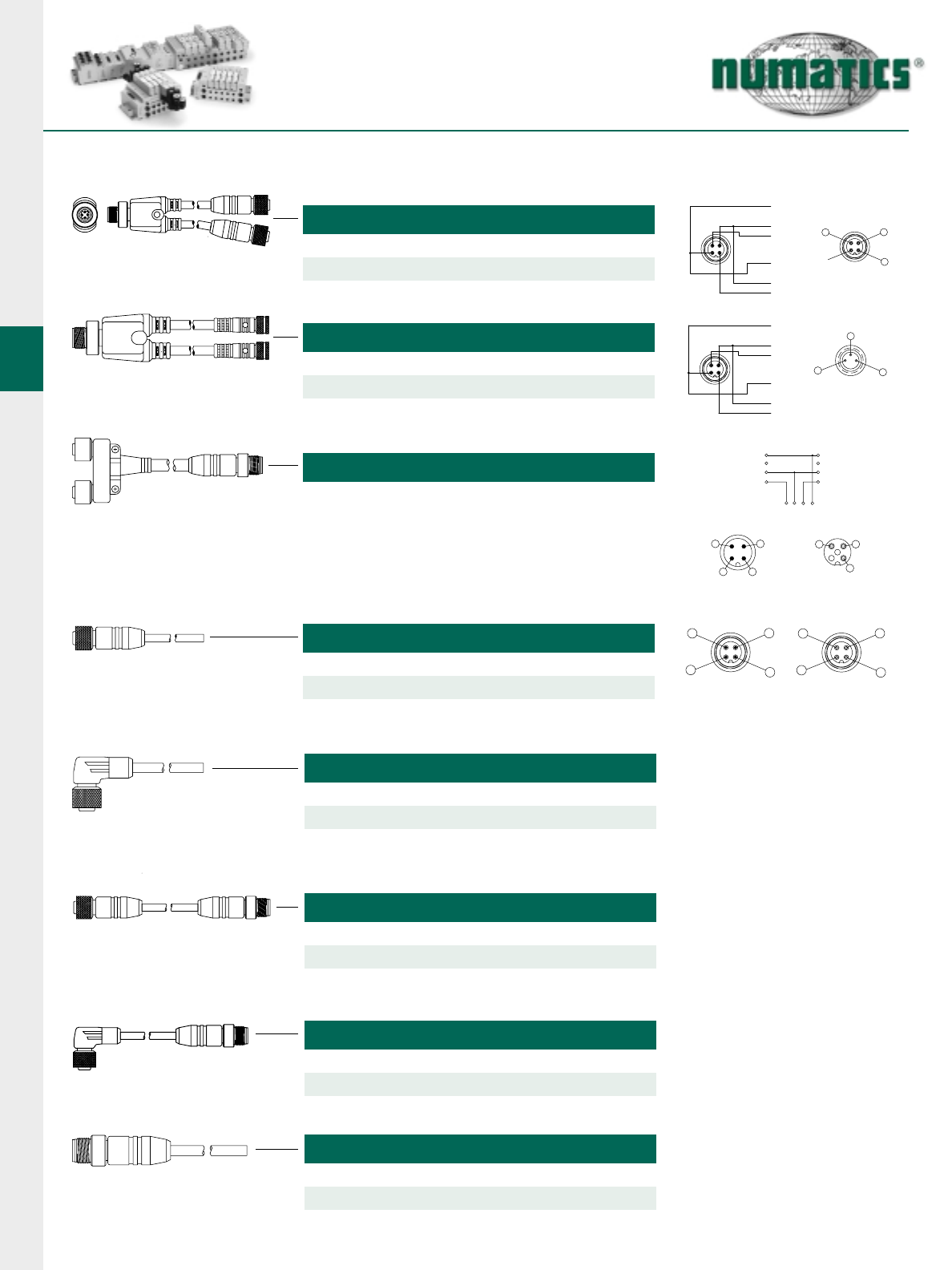
G2-2 Electronics
44 Information subject to change without notice. For ordering information or regarding your local sales office visit www.numatics.com.
A B
AB
B
A
I/O Cables, Splitters and Accessories
FEMALE
1
34
4
1
3
2
MALE
1 = BROWN
2 = N/A
3 = BLUE
4 = BLACK
Blank
1 = BROWN
4 = BLACK
3 = BLUE
2 = N/A
CABLE “A”
CABLE “B”
4
1
3
2
FEMALE
1
4
3
MALE
1 = BROWN
2 = N/A
3 = BLUE
4 = BLACK
1 = BROWN
4 = BLACK
3 = BLUE
2 = N/A
CABLE "A"
CABLE "B"
4
FACE VIEW FEMALE
4
FACE VIEW MALE
MALE CONNECTOR
12
3
4
3
1
23 1
WIRING SCHEMATIC
1
A (FEMALE)
2
4
3
1
B (FEMALE)
4
3
2
FACE VIEW FEMALE
21
34
4
1
3
2
FACE VIEW MALE
1 = Brown 3 = Blue
2 = White 4 = Black
MICRO DC SPLITTER 2 STRAIGHT MICRO FEMALE CONNECTORS
1 Meter - TA0401MC0JC05000
2 Meter - TA0402MC0JC05000
MICRO DC SPLITTER 2 STRAIGHT PICO FEMALE CONNECTORS
1 Meter - TA0401MI0KC03000
2 Meter - TA0402MI0KC03000
MICRO DC “Y”WITH MALE CABLE
0.3 Meter - TA0401FJ0JC04000
MICRO FEMALE 4 POLE STRAIGHT 22 AWG EURO COLOR CODE
2 Meter - TC0402MCE0000000
5 Meter - TC0405MCE0000000
MICRO FEMALE 4 POLE 90 DEGREE 22 AWG EURO COLOR CODE
2 Meter - TD0402MCE0000000
5 Meter - TD0405MCE0000000
MICRO F/M 4 POLE STRAIGHT 22 AWG EURO COLOR CODE
2 Meter - TC0402MC0TA04000
5 Meter - TC0405MC0TA04000
MICRO F 90°/M STRAIGHT 22 AWG EURO COLOR CODE
1 Meter - TD0401MC0TA04000
2 Meter - TD0402MC0TA04000
MICRO MALE 4 POLE STRAIGHT 22 AWG EURO COLOR CODE
2 Meter - TA0402MCE0000000
5 Meter - TA0405MCE0000000
1 Meter - TC0401MC0TA04000
5 Meter - TD0405MC0TA04000
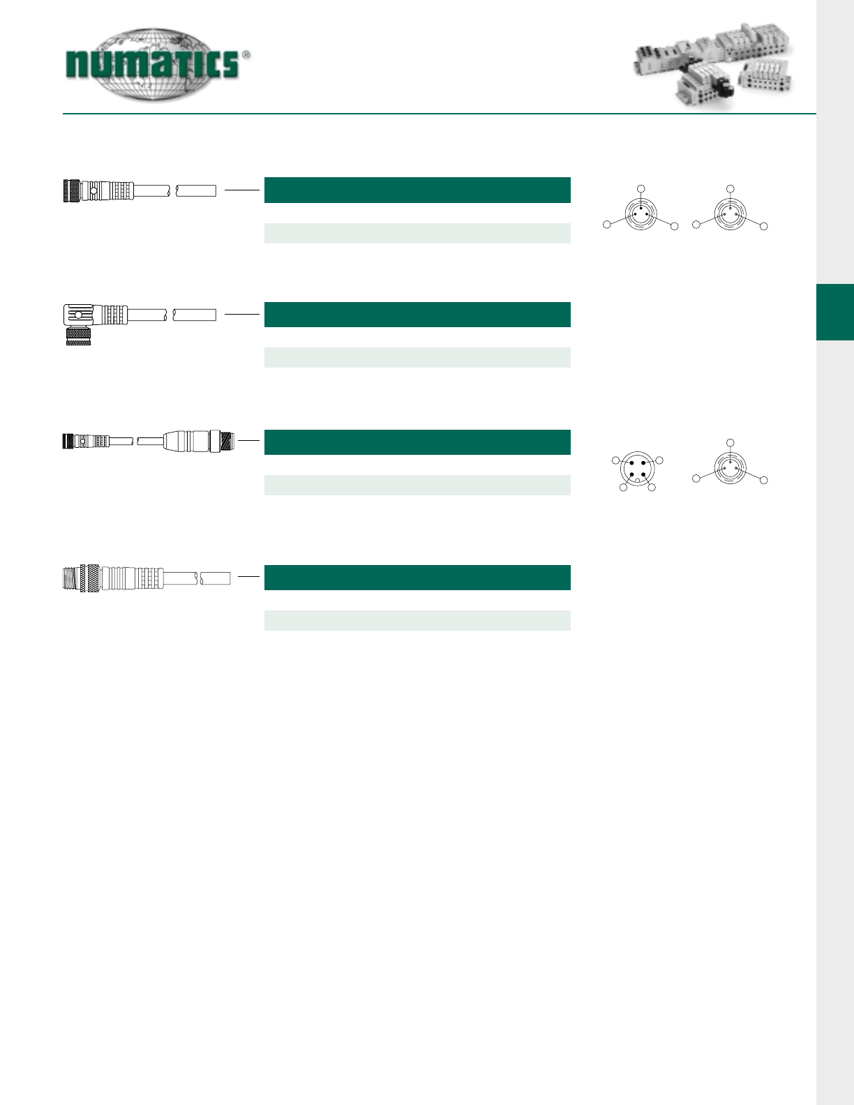
G2-2 Electronics
45
Information subject to change without notice. For ordering information or regarding your local sales office visit www.numatics.com.
I/O Cables, Splitters and Accessories continued
FACE VIEW FEMALE
1
4
3
3
4
1
FACE VIEW MALE
1 = Brown 3 = Blue
4 = Black
FACE VIEW FEMALE
1
4
3
3 = Blue
PICO FEMALE 3 POLE STRAIGHT 26 AWG EURO COLOR CODE
2 Meter - PC0302MEE0000000
5 Meter - PC0305MEE0000000
PICO FEMALE 3 POLE 90°26 AWG EURO COLOR CODE
2 Meter - PD0302MEE0000000
5 Meter - PD0305MEE0000000
MICRO MALE/PICO FEMALE 3 POLE 26 AWG EURO COLOR CODE
2 Meter - TA0302ME0PC03000
5 Meter - TA0305ME0PC03000
PICO MALE 3 POLE STRAIGHT 26 AWG EURO COLOR CODE
2 Meter - PA0302MEE0000000
5 Meter - PA0305MEE0000000
4
FACE VIEW MALE
12
3
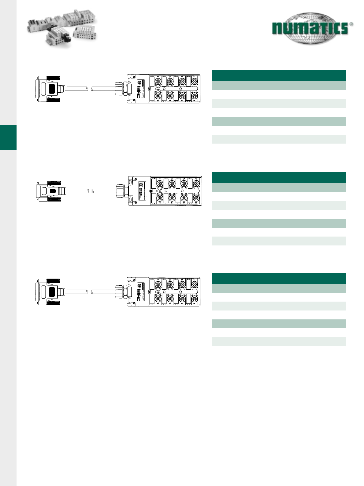
G2-2 Electronics
46 Information subject to change without notice. For ordering information or regarding your local sales office visit www.numatics.com.
Input Distribution Boxes
25 PIN SUB-D CONTR. SINGLE POINT - INPUTS
2 Meters - DB81TLNR02M25S00
5 Meters - DB81TLNR05M25S00
8 Port Distribution Box - 5 Pole 3 Wire/LED - NPN (Sinking)
10 Meters - DB81TLNR10M25S00
8 Port Distribution Box - 5 Pole 3 Wire/LED - PNP (Sourcing)
2 Meters - DB81TLPR02M25S00
5 Meters - DB81TLPR05M25S00
10 Meters - DB81TLPR10M25S00
15 PIN SUB-D CONTR. SINGLE POINT - INPUTS
2 Meters - DB81TLNR02M15S00
5 Meters - DB81TLNR05M15S00
8 Port Distribution Box - 5 Pole 3 Wire/LED - NPN (Sinking)
10 Meters - DB81TLNR10M15S00
8 Port Distribution Box - 5 Pole 3 Wire/LED - PNP (Sourcing)
2 Meters - DB81TLPR02M15S00
5 Meters - DB81TLPR05M15S00
10 Meters - DB81TLPR10M15S00
25 PIN SUB-D CONTR. DUAL POINT - INPUTS
2 Meters - DB82TLNR02M25S00
5 Meters - DB82TLNR05M25S00
8 Port Distribution Box - 5 Pole 4 Wire/LED - NPN (Sinking)
10 Meters - DB82TLNR10M25S00
8 Port Distribution Box - 5 Pole 4 Wire/LED - PNP (Sourcing)
2 Meters - DB82TLPR02M25S00
5 Meters - DB82TLPR05M25S00
10 Meters - DB82TLPR10M25S00
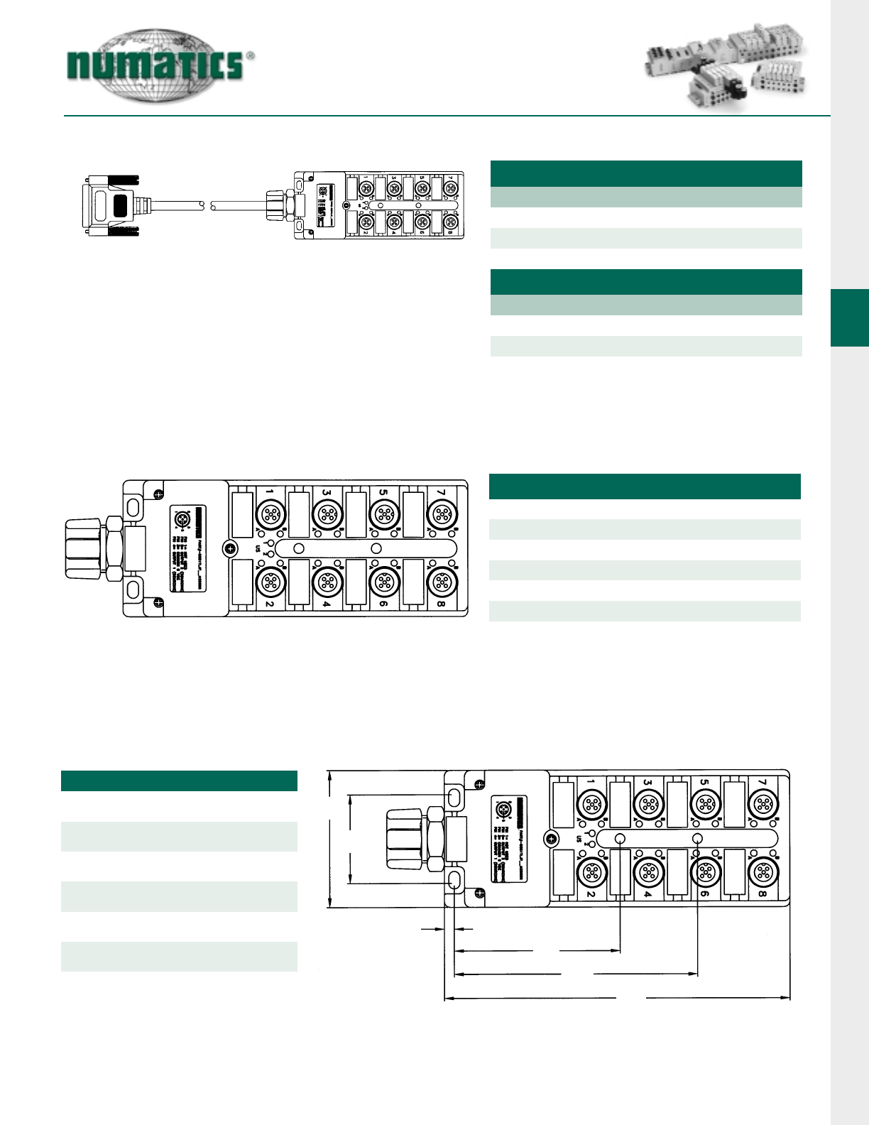
G2-2 Electronics
47
Information subject to change without notice. For ordering information or regarding your local sales office visit www.numatics.com.
Outputs Distribution Boxes and I/O D-Boxes without Cable
25 PIN SUB-D CONTR. SINGLE POINT - OUTPUTS
2 Meters - DB81TLJP02M25S00
5 Meters - DB81TLJP05M25S00
8 Port Distribution Box - 5 Pole 3 Wire/NO LED - PNP (Sourcing)
10 Meters - DB81TLJP10M25S00
8 Port Distribution Box - 5 Pole 4 Wire/NO LED - PNP (Sourcing)
2 Meters - DB82TLJP02M25S00
5 Meters - DB82TLJP05M25S00
10 Meters - DB82TLJP10M25S00
D-BOXES WITHOUT CABLE - UNIVERSAL
8 Port Block - 5 Pole w/ LED’s - NPN
DB82TLN000000000
8 Port Block - 5 Pole w/ LED’s - PNP
8 Port Block - 5 Pole without LED’s - Universal
DB82T0U000000000
DB82TLP000000000
TECHNICAL DATA
Molded
Body/Housing Pocan PBT
Threaded Sleeve CuZn, Nickel Plated
Voltage Rating 10 - 30 VDC
Amperage
Protection IP 68, NEMA 6P
Operating
Temperature
2 A per Signal
-20°C to 90°C
25 PIN SUB-D CONTR. DUAL POINT - OUTPUTS
2.36
(59.9)
1.54
(39.1)
0.18
(4.6) 2.87
(72.9)
5.98
(151.9)
4.21
(106.9)
Dimensions
top dimensions = inches
bottom dimensions (in parenthesis) = millimeters

World Headquarters
Numatics Incorporated
Phone: 248-887-4111
Fax: 248-887-9190
Numatics – Air Preparation
Phone: 810-667-3900
Fax: 810-667-3902
Numatics – Valves
Phone: 248-887-4111
Fax: 248-887-9190
Numatics – Miniature Valves
Phone: 248-960-1400
Fax: 248-960-2160
Numatics – Cylinders
Phone: 615-771-1200
Fax: 615-771-1201
Numatics – Rodless Cylinders
Phone: 519-452-1777
Fax: 519-452-3995
Numatics – Automation
Phone: 440-934-3200
Fax: 440-934-2288
CANADA
Ontario
Numatics, Ltd.
Phone: 519-452-1777
Fax: 519-452-3995
Quebec
Numatics, Ltd.
Phone: 514-332-6444
Fax: 514-332-9273
British Columbia
Numatics, Ltd.
Phone: 604-574-0401
Fax: 604-574-3713
EUROPE
Germany –
European Headquarters
Numatics GmbH
Phone: 011-49-22 41-31 60-0
Fax: 011-49-22 41-31 60 40
Hungary
Numatics Kft.
Phone: 011-36-13 82 21 35
Fax: 011-36-12 04 39 47
England
Numatics Limited
Phone: 011-44-1525-37 07 35
Fax: 011-44-1525-38 25 67
France
Numatics s.a.r.l.
Phone: 011-33-1 41 21 48 88
Fax: 011-33-1 41 21 48 89
Italy
Numatics srl
Phone: 011-39-030-373 19 99
Fax: 011-39-030-373 19 81
Netherlands
Numatics B.V.
Phone: 011-31-418-65 29 50
Fax: 011-31-418-65 29 43
Spain
Numatics Spain S.L.
Phone: 011-34-93-221 21 96
Fax: 011-34-93-221 35 14
AFRICA
South Africa
Numatics SA (Pty) Ltd.
Phone: 011-27-11-8 65 44 52
Fax: 011-27-11-8 65 42 90
LATIN & SOUTH AMERICA
Mexico
Numatics de Mexico S.A. de C.V.
Phone: 011-52-222-284 6176
Fax: 011-52-222-284 6179
Brazil
Valvair Comercial Ltda.
Phone: 011-55-12-351 2874
Fax: 011-55-12-351 1958
ASIA & PACIFIC
Australia
Numatics Australia Pty. Ltd.
Phone: 011-61-3-95 63 86 00
Fax: 011-61-3-95 63 85 11
Taiwan – Asian Headquarters
Numatics Co, Ltd. Asia
Phone: 011-886-2-29 15 16 05
Fax: 011-886-2-29 14 18 97
For a comprehensive listing of all Numatics production and distribution facilities worldwide, visit www.numatics.com
PDF-ELECT-REV9/04
