Flow Oriental Motors Bxii Series Ac Input Brushless Dc Motor Driver Packages 1505487271 User Manual
Oriental Motors Bxii Series Ac Input Brushless Dc Motor Driver Packages-1505487271 ORIENTAL_MOTORS_BXII_SERIES_AC_INPUT_BRUSHLESS_DC_MOTOR___DRIVER_PACKAGES-1505487271 ORIENTAL_MOTORS_BXII_SERIES_AC_INPUT_BRUSHLESS_DC_MOTOR___DRIVER_PACKAGES-1505487271 ORIENTAL MOTORS BXII SERIES AC INPUT BRUSHLESS DC MOTOR & DRIVER PACKAGES Motors s production assets-flotronics
2017-09-15
User Manual: Flow Oriental Motors Bxii Series Ac Input Brushless Dc Motor Driver Packages-1505487271
Open the PDF directly: View PDF ![]() .
.
Page Count: 31
D-86
D-86
ORIENTAL MOTOR GENERAL CATALOG
2015/2016 Page
Features D-86 / System Configuration D-89 / Product Line D-90 / Specifications D-92 / Characteristics D-92
Dimensions D-99 / Connection and Operation D-112 / Motor and Driver Combinations D-115
■Features
Speed Control
Contributes to Improved Takt Time with the Highest Level
of Speed Control
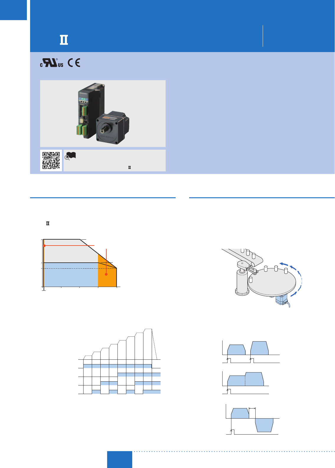
Max. speed of 4000 r/min
Speed ratio of 2000:1 (Double the ratio of conventional products)
The BX Series achieves 24000 r/min (with digital setting)✽. The
speed range has been greatly expanded.
✽304000 r/min with analog setting.
Torque
0
300010002 3 4000
Speed [r/min]
Starting Torque
2000
Continuous Duty Region
Limited Duty Region
Expanded Range
Rated Torque
Smooth Operation with Minimum Impact from the
External Environment
Speed regulation: ±0.05% (load/voltage/temperature)
Speed Selection Tailored to Load and Takt Time is Possible
Up to 16 speeds can be set
(Twice as many as conventional products)
ON
OFF
ON
OFF
FWD Input
No.0
No.1
No.2
No.3
No.4
No.5
No.6
No.7
M1 Input
ON
OFF
M2 Input
ON
OFF
M0 Input
Motor Movement
Easy Speed Control During Vertical Operation
An electromagnetic brake type motor enables stable speed
control even during vertical operation (gravitational operation). The
electromagnetic brake is automatically controlled to turn ON/OFF
according to the operation command signal to the driver. When the
power is turned OFF, such as during a blackout, the motor stops
instantaneously to hold the load in place.
Since regenerated energy is produced during vertical operation, a regeneration unit, sold separately, is required
.
Regeneration units ➜ Page D-188
Position Control
Built-in Positioning Function
Positioning operations are possible with the driver on its own. A
control module is not required.
Continuous Rotation in the Same Direction is Possible
The command position and multiple rotation data can be returned
to 0 when the command operation exceeds the round setting
range parameter. Since the multiple rotation data is returned to 0,
continuous rotation in the same direction is possible.
Application Example of Continuous Rotation in the Same Direction
[Index Mechanism]
Various Positioning Operations are Possible
Up to 16 points of operating data can be set (10 points more than
conventional products)
3 types of operation function: independent operation, linked
operation, and linked operation 2
Speed
Time
Start
Command
Operating Data
No.0
Operating Data
No.1
Speed
Time
Operating Data
No.0
Operating Data
No.1
Start
Command
Speed
Time
Dwell✽
Time
Operating Data
No.0
Operating Data
No.1
Start
Command
Independent
Operation
Linked
Operation
Linked
Operation 2
✽ Dwell time is the wait time until the next positioning operation starts.
Brushless Motor and Driver Package
BX
Series
For detailed information about regulations and standards, please see the Oriental
Motor website.
View Expanded Product Information,
Specifications, CAD, Accessories & more online.
Visit www.orientalmotor.com/catalog or use
the QR code and select "BX
Series".
•
These brushless motors can easily be used for a wide
range of applications, with characteristics similar to those
offered by servo motors.
•
In addition to speed control, they are equipped with
position control and torque limiting functions.
•
Highly accurate speed control and positioning can be
easily achieved without tuning.
<Additional Information>
•Technical reference ➜ Page H-1
•Regulations & Standards ➜ Page I-2
D-87
Brushless Motors/AC Speed Control Motors
D-87
Brushless
Motors
Overview,
Product
Series
AC Input
BMU
AC Input
BLE
AC Input
BLF
AC Input
BX
DC Input
BLH
DSC
BHF
AC Speed
Control
Motors
Accessories
Installation
CAD Data
Manuals www.orientalmotor.com Technical
Support TEL: (800) 468-3982
E-mail: techsupport@orientalmotor.com
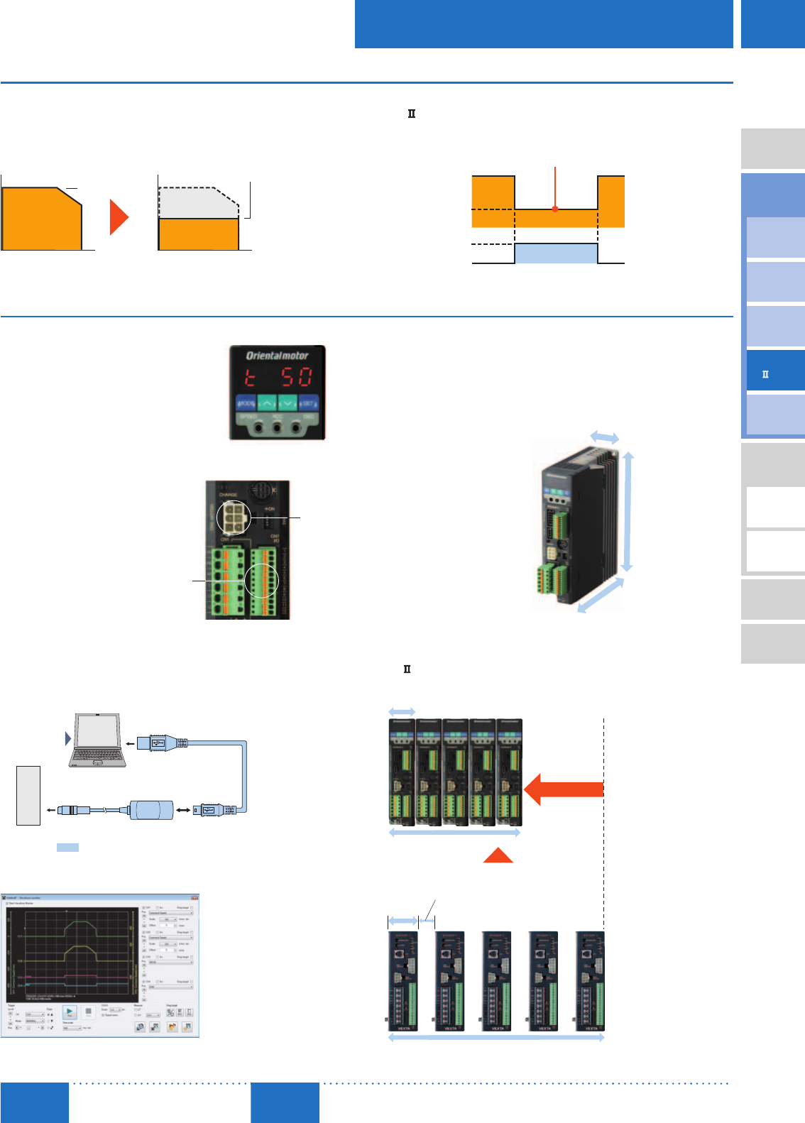
Torque Limiting
What is the Torque Limiting Function?
The setting range of the motor's starting torque (max. instantaneous
torque) can be limited to 0250% in 1% increments.
In addition to suppressing motor torque for safety purposes, this can
be utilized for a variety of applications based on the usage conditions
.
When the Torque Limiting
Value is Set at 50%
Torque Limiting Value
Max. Instantaneous
Torque
Improved Torque Limiting Accuracy
BX
±Approx. 10% (with respect to rated torque)
Torque limiting can be switched ON/OFF with an external signal
(TL input)
Max. Instantaneous
Torque
Torque Limiting Value
TL Input ON
TL Input OFF
Torque Limiting Enabled when TL Input is ON
User Friendly
Data Setting is Easy
Digital setting and operation can be
done with the driver's control panel.
Speed, load factor, current position,
operation number, etc. can be
displayed. Remote settings are also
possible when a control module
(OPX-2A), sold separately, is used.
The Display when the Load Factor is 50%
Easy Wiring
The new I/O connector does
not require a screw, which also
eliminates the need for soldering
or a special crimping tool.
The motor connector and
encoder connector can be
connected easily.
Motor
Connector
Easy
Connection
I/O Connector
Just insert a lead wire while pressing down the
orange button with a screwdriver or a pointed object.
Easy Data Editing and Monitoring
The data setting software (MEXE02) can be downloaded for free
from the Oriental Motor website. It is also available as a CD-ROM.
It is compatible with Windows 7, Vista, XP, and 2000. Besides data
editing, I/O and operating speed waveform monitoring are also possible
.
The data setting software can be downloaded from http://www.orientalmotor.com/
Computer
(Not supplied.)
Driver
Data Setting Software
MEXE02
USB Cable
0.5 m (20 in.)
PC Interface Cable
5 m (16.4 ft.)
Sold separately as accessories.
✽To connect to a computer, a dedicated device driver must be installed.
Waveform Monitoring
Effective Utilization of Installation Space
Optimized arrangement of internal parts has made the drivers
compact and slim. Multiple drivers can now be installed in contact
with each other, reducing the amount of installation space or
increasing the number of axes within the same equipment space.
Installation Area
6400mm2
(9.9 in2)
Volume Comparison
with Conventional Product
Compact Slim Body Driver
40 mm
(1.57 in.)
120 mm
(4.72 in.)
160 mm
(6.30 in.)
Approx. 5% Reduction
Conventional Product
BX Series Driver
45 mm
(1.77 in.)
25 mm (0.98 in.)
325 mm (12.8 in.)
BX Series Driver
40 mm
(1.57 in.)
200 mm (7.87 in.)
Installation
Width
38%
Multiple Units can be Installed in Contact with Each Other
Reduction
D-88
D-88 Brushless Motors/BX
Series
ORIENTAL MOTOR GENERAL CATALOG
2015/2016 Page
Features D-86 / System Configuration D-89 / Product Line D-90 / Specifications D-92 / Characteristics D-92
Dimensions D-99 / Connection and Operation D-112 / Motor and Driver Combinations D-115
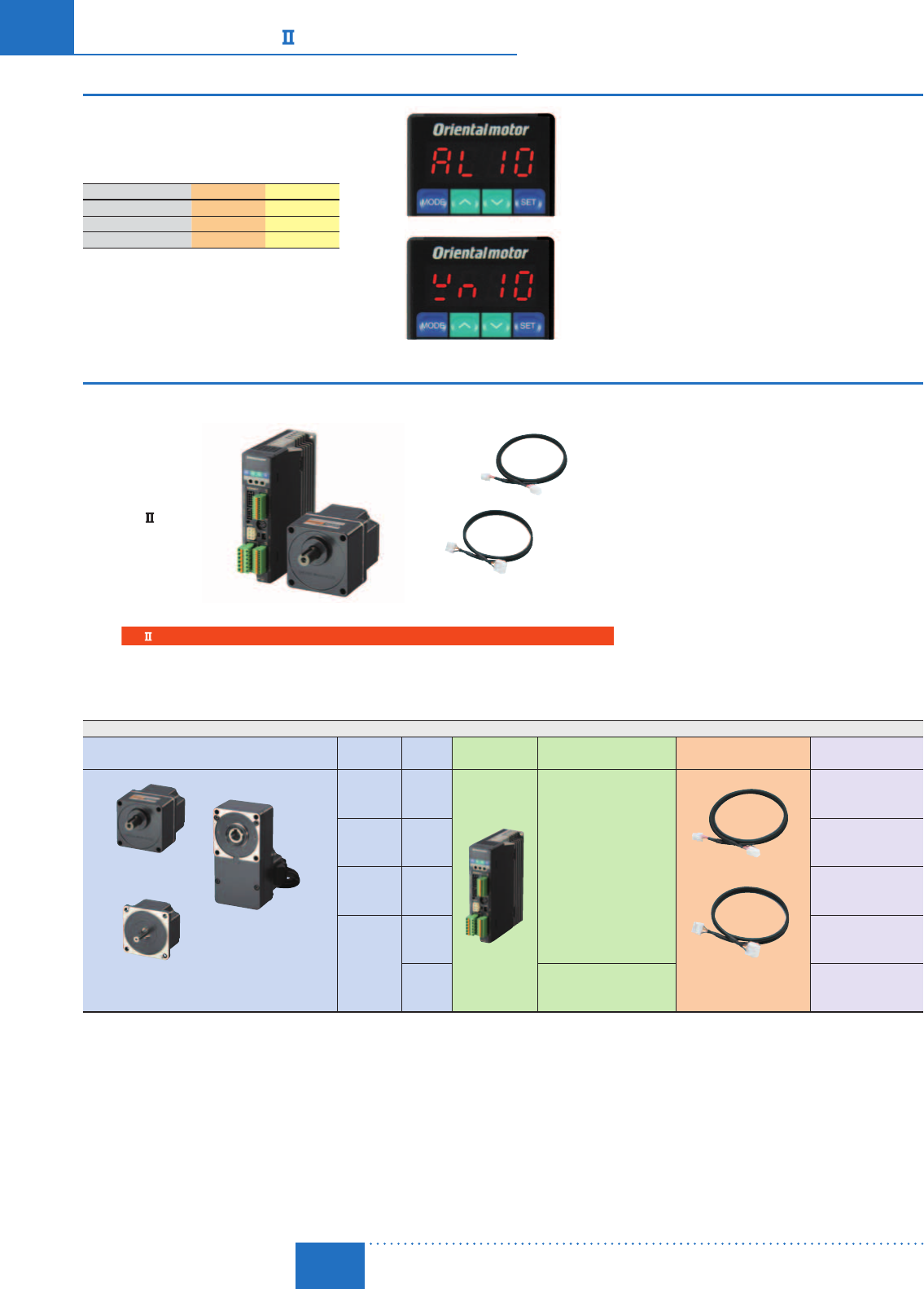
Value Priced
Motor + Gear + Driver + Cables + Software = Value
$936.00
BX Series
60 W (1/12 HP) motor
Combination type with a
parallel shaft gearhead
Gear ratio 30
Digital Setting is
Possible with Just the
Driver. Greatly Increased
Functionality.
+
Connection Cable Included
Cable for Motor
Cable for Encoder
BX Series
■Product Line
Conform to the voltage specifications of many countries around the world.
Motor and Driver Package
Motor Type Frame Size Output
Power Driver Power Supply Voltage Connection Cable Package Price Range
Round Shaft Type
Combination Type
(Parallel shaft gear)
Combination Type
(Hollow shaft flat gear)
Electromagnetic brake types are available for all types.
60 mm
(2.36 in.)
30 W
1/25 HP
Single-phase 100-120 VAC
Single-phase 200-240 VAC
Three-phase 200-240 VAC
Cable for Motor
Cable for Encoder
3 m (9.8 ft.)
$753.00$1,165.00
80 mm
(3.15 in.)
60 W
1/12 HP $787.00$1,248.00
90 mm
(3.54 in.)
120 W
1/6 HP $799.00$1,337.00
104 mm
(4.09 in.)
200 W
1/4 HP $790.00$1,305.00
400 W
1/2 HP
Single-phase 200-240 VAC
Three-phase 200-240 VAC $962.00$1,457.00
Can be extended to a maximum of 30.4 m (99.7 ft.) with an accessory cable.
Reliability
Alarm Code
10 display
Warning Code
10 display
Sink/Source Logic can be Selected
It is possible to switch between sink/source
logic according to the external controller by
changing the wiring .
Peace of Mind even if a Problem Occurs
Quick response to a problem is possible thanks to
the alarm (protective function) and warning that is
output prior to an alarm.
Display Examples Alarm Warning
· Overfl ow 10 10
· Overvoltage 22 22
· Overload 30 30
D-89
Brushless Motors/AC Speed Control Motors
D-89
Brushless
Motors
Overview,
Product
Series
AC Input
BMU
AC Input
BLE
AC Input
BLF
AC Input
BX
DC Input
BLH
DSC
BHF
AC Speed
Control
Motors
Accessories
Installation
CAD Data
Manuals www.orientalmotor.com Technical
Support TEL: (800) 468-3982
E-mail: techsupport@orientalmotor.com
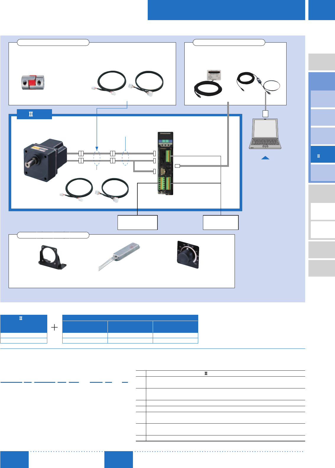
■ System Configuration ✽Not supplied
Control Module
➜Page A-303
Data Setting Software
Communication Cable
➜Page A-303
Accessories (Sold separately)
Example of System Confi guration
BX
Series
Combination Type –
Parallel Shaft
Sold Separately
Connection Cable
[7 m (23.0 ft.)] Mounting Bracket Flexible Coupling
BXS6200A-50S-3 CC07SBF SOL6M8 MCL652222
$998.00 $167.00 $37.00 $191.00
The system configuration shown above is an example. Other combinations are also available.
or
Flexible Couplings
➜Page D-190
Connection Cables, Flexible Connection Cables
➜Page D-184
Accessories (Sold separately)
To USB Port
Combination Type
(Motor and gearhead)
Conversion Cable
(Included)
Driver
Connection Cable (Included)
BX
Series
AC Power Supply
(Main power supply)
Programmable
Controller✽
Computer✽
Data Setting Software
MEXE02
MEXE02 can be downloaded
from the Oriental Motor website.
Mounting Brackets
➜Page D-190
Regeneration Units
➜Page D-188
External Speed Potentiometer
➜Page D-187
Accessories (Sold separately)
The User's Manual, which describes how to operate the product, is available. For details, please contact the nearest Oriental Motor sales office, or download
from the Oriental Motor website. http://www.orientalmotor.com/
■Product Number
⑥① ② ③ ④ ⑤⑦⑧
BXS6200AM-10S-3 ①Series Name BXS: BX
Series
②Motor Frame Size 2: 60 mm (2.36 in.) 4: 80 mm (3.15 in.) 5: 90 mm (3.54 in.)
6: 104 mm (4.09 in.) (110 mm (4.33 in.) for gearhead)
③Output Power (W) 30: 30 W (1/25 HP) 60: 60 W (1/12 HP) 120: 120 W (1/6 HP)
200: 200 W (1/4 HP) 400: 400 W (1/2 HP)
④Power Supply Voltage A: Single-Phase 100-120 VAC C: Single-Phase, Three-Phase 200-240 VAC
⑤M: Electromagnetic Brake Type Blank: Standard Type
⑥Gear Ratio and Shaft
Confi guration
Number: Gear ratio for combination types
A: Round Shaft Type
⑦Gearhead Type
(Combination type only)
S: Parallel Shaft Gearhead
FR: Hollow Shaft Flat Gearhead
⑧Connection Cable 3: Length of the included connection cable is 3 m (9.8 ft.)

D-90
D-90 Brushless Motors/BX
Series
ORIENTAL MOTOR GENERAL CATALOG
2015/2016 Page
Features D-86 / System Configuration D-89 / Product Line D-90 / Specifications D-92 / Characteristics D-92
Dimensions D-99 / Connection and Operation D-112 / Motor and Driver Combinations D-115
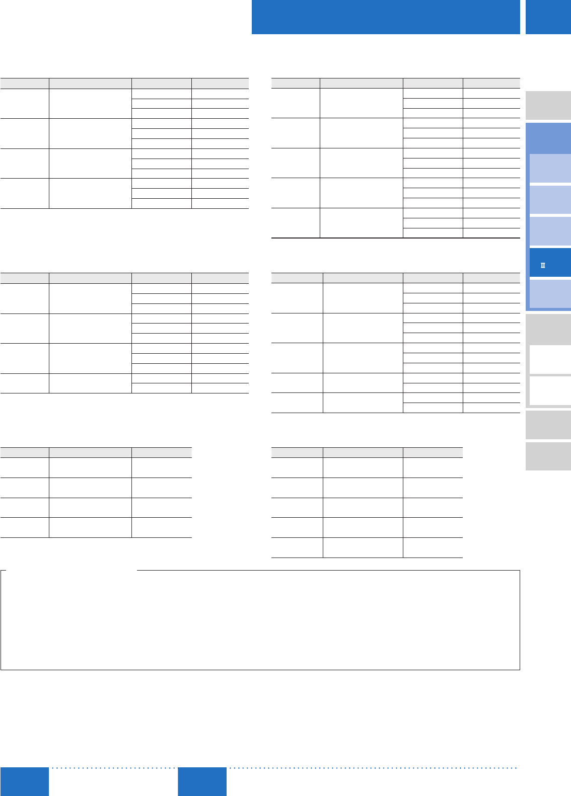
■Product Line
Combination Type
The combination type comes with a motor and gearhead pre-assembled.
The combination of motors and gearheads can be changed, and they are also available separately.
In addition, the gearhead can be removed and the assembly position can be changed in 90˚ increments.
Standard Type
Combination Type, Parallel Shaft Gearhead
Single-Phase 100-120 VAC
Output Power Product Name Gear Ratio List Price
30 W
(1/25 HP) BXS230A-□S-3
5, 10, 15, 20 $879.00
30, 50, 100 $888.00
200 $897.00
60 W
(1/12 HP) BXS460A-□S-3
5, 10, 15, 20 $928.00
30, 50, 100 $936.00
200 $946.00
120 W
(1/6 HP) BXS5120A-□S-3
5, 10, 15, 20 $969.00
30, 50, 100 $980.00
200 $990.00
200 W
(1/4 HP) BXS6200A-□S-3
5, 10, 15, 20 $988.00
30, 50 $998.00
100, 200 $1,014.00
Single-Phase, Three-Phase 200-240 VAC
Output Power Product Name Gear Ratio List Price
30 W
(1/25 HP) BXS230C-□S-3
5, 10, 15, 20 $904.00
30, 50, 100 $913.00
200 $922.00
60 W
(1/12 HP) BXS460C-□S-3
5, 10, 15, 20 $953.00
30, 50, 100 $961.00
200 $971.00
120 W
(1/6 HP) BXS5120C-□S-3
5, 10, 15, 20 $989.00
30, 50, 100 $1,000.00
200 $1,010.00
200 W
(1/4 HP) BXS6200C-□S-3
5, 10, 15, 20 $1,008.00
30, 50 $1,018.00
100, 200 $1,034.00
400 W
(1/2 HP) BXS6400C-□S-3
5, 10, 15, 20 $1,160.00
30, 50 $1,170.00
100, 200 $1,186.00
Combination Type, Hollow Shaft Flat Gearhead
Single-Phase 100-120 VAC
Output Power Product Name Gear Ratio List Price
30 W
(1/25 HP) BXS230A-□FR-3
5, 10, 15, 20 $937.00
30, 50, 100 $949.00
200 $961.00
60 W
(1/12 HP) BXS460A-□FR-3
5, 10, 15, 20 $1,020.00
30, 50, 100 $1,032.00
200 $1,044.00
120 W
(1/6 HP) BXS5120A-□FR-3
5, 10, 15, 20 $1,067.00
30, 50, 100 $1,078.00
200 $1,090.00
200 W
(1/4 HP) BXS6200A-□FR-3 10, 15, 20 $1,071.00
30, 50, 100 $1,082.00
Single-Phase, Three-Phase 200-240 VAC
Output Power Product Name Gear Ratio List Price
30 W
(1/25 HP) BXS230C-□FR-3
5, 10, 15, 20 $962.00
30, 50, 100 $974.00
200 $986.00
60 W
(1/12 HP) BXS460C-□FR-3
5, 10, 15, 20 $1,045.00
30, 50, 100 $1,057.00
200 $1,069.00
120 W
(1/6 HP) BXS5120C-□FR-3
5, 10, 15, 20 $1,087.00
30, 50, 100 $1,098.00
200 $1,110.00
200 W
(1/4 HP) BXS6200C-□FR-3 10, 15, 20 $1,091.00
30, 50, 100 $1,102.00
400 W
(1/2 HP) BXS6400C-□FR-3 5, 10, 15, 20 $1,243.00
30, 50, 100 $1,254.00
Round Shaft Type
Single-Phase 100-120 VAC
Output Power Product Name List Price
30 W
(1/25 HP) BXS230A-A-3 $753.00
60 W
(1/12 HP) BXS460A-A-3 $787.00
120 W
(1/6 HP) BXS5120A-A-3 $799.00
200 W
(1/4 HP) BXS6200A-A-3 $790.00
Single-Phase, Three-Phase 200-240 VAC
Output Power Product Name List Price
30 W
(1/25 HP) BXS230C-A-3 $778.00
60 W
(1/12 HP) BXS460C-A-3 $812.00
120 W
(1/6 HP) BXS5120C-A-3 $819.00
200 W
(1/4 HP) BXS6200C-A-3 $810.00
400 W
(1/2 HP) BXS6400C-A-3 $962.00
A number indicating the gear ratio is entered where the box □ is located within the product name.
The following items are included with each product.
Combination Type with a Parallel Shaft Gearhead
Motor, Gearhead, Driver, Conversion Cable, Connection Cable, CN1 Connector, CN5 Connector, CN7 Connector, Mounting Brackets for Driver (screws included), Installation Screws, Parallel Key,
Operating Manual
Combination Type with a Hollow Shaft Flat Gearhead
Motor, Gearhead, Driver, Conversion Cable, Connection Cable, CN1 Connector, CN5 Connector, CN7 Connector, Mounting Brackets for Driver (screws included), Installation Screws, Parallel Key,
Safety Cover (screws included), Operating Manual
Round Shaft Type
Motor, Driver, Conversion Cable, Connection Cable, CN1 Connector, CN5 Connector, CN7 Connector, Mounting Brackets for Driver (screws included), Operating Manual
D-91
Brushless Motors/AC Speed Control Motors
D-91
Brushless
Motors
Overview,
Product
Series
AC Input
BMU
AC Input
BLE
AC Input
BLF
AC Input
BX
DC Input
BLH
DSC
BHF
AC Speed
Control
Motors
Accessories
Installation
CAD Data
Manuals www.orientalmotor.com Technical
Support TEL: (800) 468-3982
E-mail: techsupport@orientalmotor.com
The following items are included with each product.
Combination Type with a Parallel Shaft Gearhead
Motor, Gearhead, Driver, Conversion Cable, Connection Cable, CN1 Connector, CN5 Connector, CN7 Connector, Mounting Brackets for Driver (screws included), Installation Screws, Parallel Key,
Operating Manual
Combination Type with a Hollow Shaft Flat Gearhead
Motor, Gearhead, Driver, Conversion Cable, Connection Cable, CN1 Connector, CN5 Connector, CN7 Connector, Mounting Brackets for Driver (screws included), Installation Screws, Parallel Key,
Safety Cover (screws included), Operating Manual
Round Shaft Type
Motor, Gearhead, Driver, Conversion Cable, Connection Cable, CN1 Connector, CN5 Connector, CN7 Connector, Mounting Brackets for Driver (screws included), Operating Manual
With Electromagnetic Brake
Combination Type, Parallel Shaft Gearhead
Single-Phase 100-120 VAC
Output Power Product Name Gear Ratio List Price
30 W
(1/25 HP) BXS230AM-□S-3
5, 10, 15, 20 $1,058.00
30, 50, 100 $1,067.00
200 $1,076.00
60 W
(1/12 HP) BXS460AM-□S-3
5, 10, 15, 20 $1,107.00
30, 50, 100 $1,115.00
200 $1,125.00
120 W
(1/6 HP) BXS5120AM-□S-3
5, 10, 15, 20 $1,196.00
30, 50, 100 $1,207.00
200 $1,217.00
200 W
(1/4 HP) BXS6200AM-□S-3
5, 10, 15, 20 $1,191.00
30, 50 $1,201.00
100, 200 $1,217.00
Single-Phase, Three-Phase 200-240 VAC
Output Power Product Name Gear Ratio List Price
30 W
(1/25 HP) BXS230CM-□S-3
5, 10, 15, 20 $1,083.00
30, 50, 100 $1,092.00
200 $1,101.00
60 W
(1/12 HP) BXS460CM-□S-3
5, 10, 15, 20 $1,132.00
30, 50, 100 $1,140.00
200 $1,150.00
120 W
(1/6 HP) BXS5120CM-□S-3
5, 10, 15, 20 $1,216.00
30, 50, 100 $1,227.00
200 $1,237.00
200 W
(1/4 HP) BXS6200CM-□S-3
5, 10, 15, 20 $1,211.00
30, 50 $1,221.00
100, 200 $1,237.00
400 W
(1/2 HP) BXS6400CM-□S-3
5, 10, 15, 20 $1,363.00
30, 50 $1,373.00
100, 200 $1,389.00
Combination Type, Hollow Shaft Flat Gearhead
Single-Phase 100-120 VAC
Output Power Product Name Gear Ratio List Price
30 W
(1/25 HP) BXS230AM-□FR-3
5, 10, 15, 20 $1,116.00
30, 50, 100 $1,128.00
200 $1,140.00
60 W
(1/12 HP) BXS460AM-□FR-3
5, 10, 15, 20 $1,199.00
30, 50, 100 $1,211.00
200 $1,223.00
120 W
(1/6 HP) BXS5120AM-□FR-3
5, 10, 15, 20 $1,294.00
30, 50, 100 $1,305.00
200 $1,317.00
200 W
(1/4 HP) BXS6200AM-□FR-3 10, 15, 20 $1,274.00
30, 50, 100 $1,285.00
Single-Phase, Three-Phase 200-240 VAC
Output Power Product Name Gear Ratio List Price
30 W
(1/25 HP) BXS230CM-□FR-3
5, 10, 15, 20 $1,141.00
30, 50, 100 $1,153.00
200 $1,165.00
60 W
(1/12 HP) BXS460CM-□FR-3
5, 10, 15, 20 $1,224.00
30, 50, 100 $1,236.00
200 $1,248.00
120 W
(1/6 HP) BXS5120CM-□FR-3
5, 10, 15, 20 $1,314.00
30, 50, 100 $1,325.00
200 $1,337.00
200 W
(1/4 HP) BXS6200CM-□FR-3 10, 15, 20 $1,294.00
30, 50, 100 $1,305.00
400 W
(1/2 HP) BXS6400CM-□FR-3 5, 10, 15, 20 $1,446.00
30, 50, 100 $1,457.00
Round Shaft Type
Single-Phase 100-120 VAC
Output Power Product Name List Price
30 W
(1/25 HP) BXS230AM-A-3 $932.00
60 W
(1/12 HP) BXS460AM-A-3 $966.00
120 W
(1/6 HP) BXS5120AM-A-3 $1,026.00
200 W
(1/4 HP) BXS6200AM-A-3 $993.00
Single-Phase, Three-Phase 200-240 VAC
Output Power Product Name List Price
30 W
(1/25 HP) BXS230CM-A-3 $957.00
60 W
(1/12 HP) BXS460CM-A-3 $991.00
120 W
(1/6 HP) BXS5120CM-A-3 $1,046.00
200 W
(1/4 HP) BXS6200CM-A-3 $1,013.00
400 W
(1/2 HP) BXS6400CM-A-3 $1,165.00
A number indicating the gear ratio is entered where the box □ is located within the product name.
D-92
D-92 Brushless Motors/BX
Series
ORIENTAL MOTOR GENERAL CATALOG
2015/2016 Page
Features D-86 / System Configuration D-89 / Product Line D-90 / Specifications D-92 / Characteristics D-92
Dimensions D-99 / Connection and Operation D-112 / Motor and Driver Combinations D-115
■Specifications
30 W (1/25 HP), 60 W (1/12 HP), 120 W (1/6 HP)
Product
Name
Standard
Single-phase
100-120 VAC
Combination Type BXS230A-□
■
■ -3 BXS460A-□
■
■ -3 BXS5120A-□
■
■ -3
Round Shaft Type BXS230A-A-3 BXS460A-A-3 BXS5120A-A-3
Single-Phase/Three-
Phase 200-240 VAC
Combination Type BXS230C-□
■
■ -3 BXS460C-□
■
■ -3 BXS5120C-□
■
■ -3
Round Shaft Type BXS230C-A-3 BXS460C-A-3 BXS5120C-A-3
Electromagnetic
Brake Type
Single-phase
100-120 VAC
Combination Type BXS230AM-□
■
■ -3 BXS460AM-□
■
■ -3 BXS5120AM-□
■
■ -3
Round Shaft Type BXS230AM-A-3 BXS460AM-A-3 BXS5120AM-A-3
Single-Phase/Three-
Phase 200-240 VAC
Combination Type BXS230CM-□
■
■ -3 BXS460CM-□
■
■ -3 BXS5120CM-□
■
■ -3
Round Shaft Type BXS230CM-A-3 BXS460CM-A-3 BXS5120CM-A-3
Rated Output Power (Continuous) W (HP) 30 (1/25) 60 (1/12) 120 (1/6)
Rated Speed r/min 3000
Rated Torque N·m (oz-in) 0.1 (14.2) 0.2 (28) 0.4 (56)
Maximum Instantaneous Torque N·m (oz-in) 0.2 (28) 0.4 (56) 0.8 (113)
Rotor Inertia J: ×10-4kg·m2 (oz-in2) 0.087 (0.48) 0.24 (1.31) 0.63 (3.4)
Round Shaft Type Permissible Inertia J: ×10-4kg·m2 (oz-in2) 1.5 (8.2) 3 (16.4) 6 (33)
Speed Control Mode
Speed Control Range Digital setting: 24000 r/min (2000:1)
Analog setting: 304000 r/min (133:1)
Speed Regulation
Load ±0.05% or less: Conditions 0rated torque, rated speed, rated voltage, normal temperature
Voltage ±0.05% or less: Conditions Rated voltage −15+10%, rated speed, no load, normal temperature
Temperature ±0.05% (±0.5%)✽1 or less: Conditions Operating ambient temperature 0+50˚C (+32+122°F),
rated speed, no load, rated voltage
Torque Limiting Setting Range 0250%
Position Control Mode
Traveling Amount Setting Range −8,388,608+8,388,607 step
Resolution 0.72˚ (1 rotation: 500 pulses)
Speed Setting Range Digital setting: 24000 r/min (2000:1)
Torque Limiting Setting Range 0250%
Power-Supply Input
Rated Voltage
Single-phase 100-120 VAC −15+10%
Single-phase 200-240 VAC −15+10%
Three-phase 200-240 VAC −15+10%
Frequency 50/60 Hz ±5%
Rated Input Current
A
Single-Phase 100-120 VAC 1.4 2.2 3.7
Single-Phase 200-240 VAC 0.8 1.4 2.3
Three-Phase 200-240 VAC 0.5 0.7 1.1
Max. Input Current
A
Single-Phase 100-120 VAC 4.0 5.5 9.8
Single-Phase 200-240 VAC 2.2 3.0 5.5
Three-Phase 200-240 VAC 1.3 1.9 3.4
For Electromagnetic
Brake✽2
Type Power off activated type, automatically controlled by the driver
Static Friction Torque N·m (oz-in) 0.1 (14.2) 0.2 (28) 0.4 (56)
Gravitational
Operation
Capability✽3
Continuous Regenerative Power W (HP) 100 (1/8)
Instantaneous Regenerative Power W (HP) 240 (1/3)
Applicable Regeneration Unit EPRC-400P (Accessories)
✽1 Specification for analog setting.
✽2 Specification for electromagnetic brake type only.
Do not start or stop the motor by turning ON/OFF the power supply, as it will cause abnormal wear of the electromagnetic brake.
✽3 Values when regeneration unit is used.
Install the regeneration unit in a place that has the same heat radiation capability as the heat sink (material: aluminum, 350×350 mm (13.8×13.8 in.), 3 mm (0.12 in.) thick).
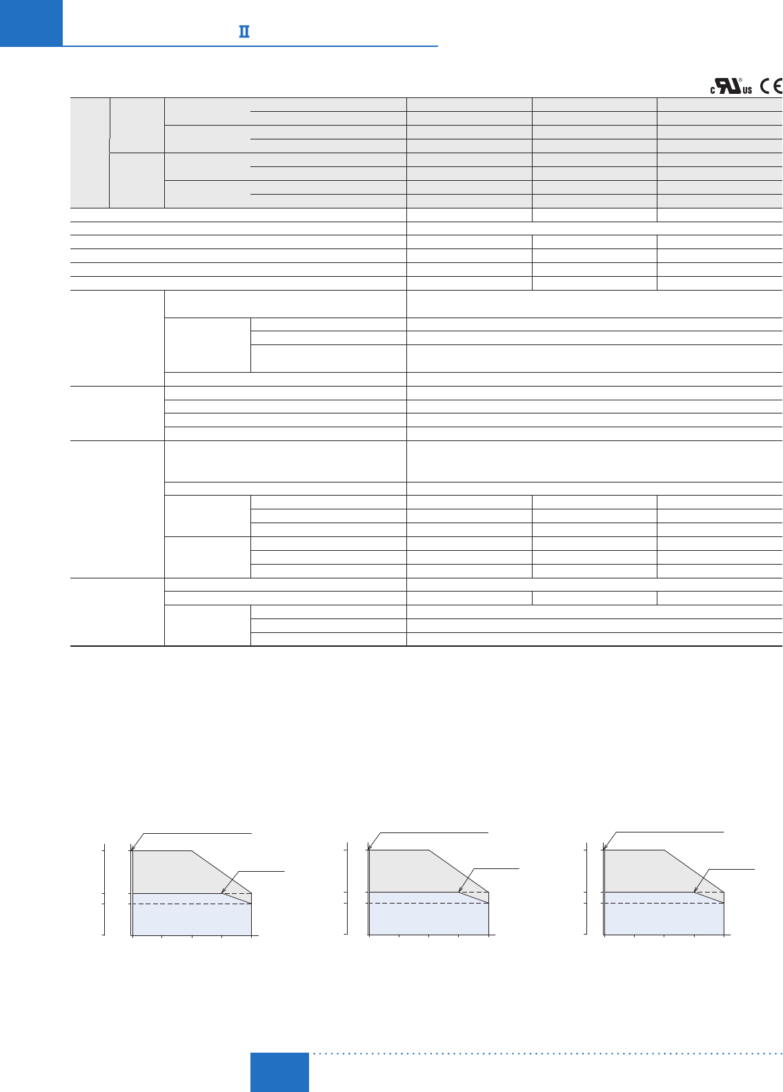
■Speed – Torque Characteristics
Continuous Duty Region : Continuous operation is possible in this region.
Limited Duty Region : This region is used primarily when accelerating. Please note that when a load that exceeds the rated torque is applied
continuously for approximately 5 seconds, the overload protective function is activated and the motor coasts to a
stop.
30 W (1/25 HP) 60 W (1/12 HP) 120 W (1/6 HP)
4000
0
Continuous Duty Region
Limited Duty Region
1000 2000 3000
0.075
0.1
0.2
2 (30)
Rated Torque
Maximum Instantaneous Torque
[N·m]
Speed [r/min]
[oz-in]
0
10.6
14.2
28
Torque
40001000 2000 30002 (30)
Rated Torque
Maximum Instantaneous Torque
Speed [r/min]
0.2
0
Continuous Duty Region
Limited Duty Region
0.4
0.15
[N·m]
[oz-in]
28
0
56
21
Torque
40001000 2000 30002 (30)
Rated Torque
Maximum Instantaneous Torque
0.4
0
Continuous Duty Region
Limited Duty Region
0.8
0.3
Speed [r/min]
[N·m]
[oz-in]
56
0
113
42
Torque
If in speed control mode, the speed control range changes depending on the speed setting method. If in position control mode, digital settings are used.
Digital Setting: 24000 r/min
Analog Setting: 304000 r/min
The values correspond to each specification and characteristics of a stand-alone motor. The speed - torque characteristics show the values when rated voltage is applied.
A number indicating the gear ratio is entered where the box □ is located within the product name.
Either S (parallel shaft gearhead) or FR (hollow shaft flat gearhead) indicating a type of the combination type is entered where the box
■
■ is located within the product name.
D-93
Brushless Motors/AC Speed Control Motors
D-93
Brushless
Motors
Overview,
Product
Series
AC Input
BMU
AC Input
BLE
AC Input
BLF
AC Input
BX
DC Input
BLH
DSC
BHF
AC Speed
Control
Motors
Accessories
Installation
CAD Data
Manuals www.orientalmotor.com Technical
Support TEL: (800) 468-3982
E-mail: techsupport@orientalmotor.com
200 W (1/4 HP), 400 W (1/2 HP)
Product
Name
Standard
Single-Phase
100-120 VAC
Combination Type BXS6200A-□
■
■ -3 −
Round Shaft Type BXS6200A-A-3 −
Single-Phase/Three-
Phase 200-240 VAC
Combination Type BXS6200C-□
■
■ -3 BXS6400C-□
■
■ -3
Round Shaft Type BXS6200C-A-3 BXS6400C-A-3
Electromagnetic
Brake Type
Single-Phase
100-120 VAC
Combination Type BXS6200AM-□
■
■ -3 −
Round Shaft Type BXS6200AM-A-3 −
Single-Phase/Three-
Phase 200-240 VAC
Combination Type BXS6200CM-□
■
■ -3 BXS6400CM-□
■
■ -3
Round Shaft Type BXS6200CM-A-3 BXS6400CM-A-3
Rated Output Power (Continuous) W (HP) 200 (1/4) 400 (1/2)
Rated Speed r/min 3000
Rated Torque N·m (oz-in) 0.65 (92) 1.3 (184)
Maximum Instantaneous Torque N·m (oz-in) 1.3 (184) 2.6 (360)
Rotor Inertia J: ×10-4kg·m2 (oz-in2) 0.66 (3.6) 0.66 (3.6)
Round Shaft Type Permissible Inertia J: ×10-4kg·m2 (oz-in2) 10 (55) 17.5 (96)
Speed Control Mode
Speed Control Range Digital setting: 24000 r/min (2000:1)
Analog setting: 304000 r/min (133:1)
Speed Regulation
Load ±0.05% or less: Conditions 0rated torque, rated speed, rated voltage, normal temperature
Voltage ±0.05% or less: Conditions Rated voltage −15+10%, rated speed, no load, normal temperature
Temperature ±0.05% (±0.5%)✽1 or less: Conditions Operating ambient temperature 0+50˚C (+32+122°F),
rated speed, no load, rated voltage
Torque Limiting Setting Range 0250%
Position Control Mode
Traveling Amount Setting Range −8,388,608+8,388,607 step
Resolution 0.72˚ (1 rotation: 500 pulses)
Speed Setting Range Digital Setting: 24000 r/min (2000:1)
Torque Limiting Setting Range 0250%
Power Supply Input
Rated Voltage
Single-Phase 100-120 VAC −15+10%
Single-Phase 200-240 VAC −15+10%
Three-Phase 200-240 VAC −15+10%
Single-Phase 200-240 VAC −15+10%
Three-Phase 200-240 VAC −15+10%
Frequency 50/60 Hz ±5%
Rated Input Current
A
Single-Phase 100-120 VAC 4.7 −
Single-Phase 200-240 VAC 2.8 4.7
Three-Phase 200-240 VAC 1.7 2.8
Max. Input Current
A
Single-Phase 100-120 VAC 11.3 −
Single-Phase 200-240 VAC 7.1 9.8
Three-Phase 200-240 VAC 4.5 6.4
For Electromagnetic
Brake✽2
Type Power off activated type, automatically controlled by the driver
Static Friction Torque N·m (oz-in) 0.65 (92) 1.3 (184)
Gravitational
Operation
Capability✽3
Continuous Regenerative Power W (HP) 100 (1/8)
Instantaneous Regenerative Power W (HP) 800 (1)
Applicable Regeneration Unit RGB100 (Accessory)
✽1 Specification for analog setting.
✽2 Specification for electromagnetic brake type only.
Do not start or stop the motor by turning ON/OFF the power supply, as it will cause abnormal wear of the electromagnetic brake.
✽3 Values when regeneration unit is used.
Install the regeneration unit in a place that has the same heat radiation capability as the heat sink (material: aluminum, 350×350 mm (13.8×13.8 in.), 3 mm (0.12 in.) thick).
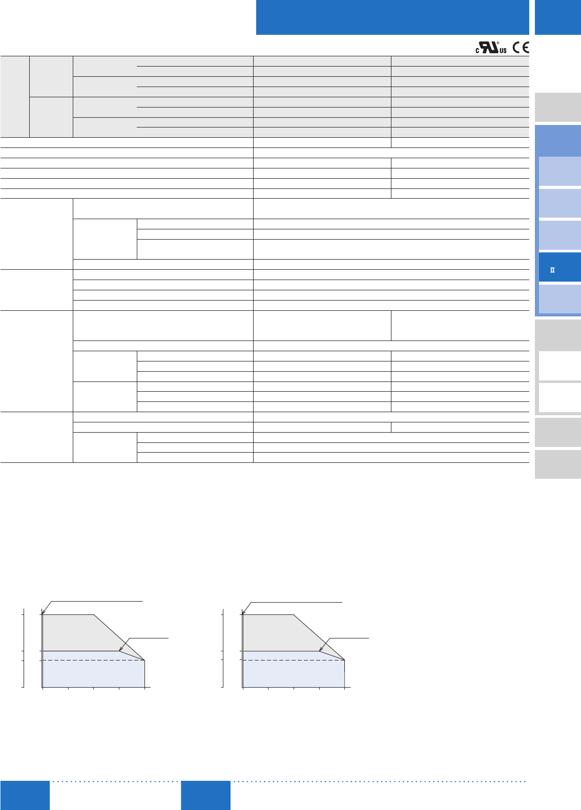
■Speed – Torque Characteristics
Continuous Duty Region : Continuous operation is possible in this region.
Limited Duty Region : This region is used primarily when accelerating. When a load that exceeds the rated torque is applied continuously for
approximately 5 seconds, the overload protective function is activated and the motor coasts to a stop.
200 W (1/4 HP) 400 W (1/2 HP)
40001000 2000 30002 (30)
Rated Torque
Maximum Instantaneous Torque
0.65
0
Continuous Duty Region
Limited Duty Region
1.3
0.48
[N·m]
Speed [r/min]
[oz-in]
92
0
184
68
Torque
40001000 2000 30002 (30)
Rated Torque
Maximum Instantaneous Torque
Speed [r/min]
0
Continuous Duty Region
Limited Duty Region
2.6
1.3
0.95
[N·m]
[oz-in]
0
369
184
134
Torque
If in speed control mode, the speed control range changes depending on the speed setting method. If in position control mode, digital settings are used.
Digital Setting: 24000 r/min
Analog Setting: 304000 r/min
The values correspond to each specification and characteristics of a stand-alone motor. The speed - torque characteristics show the values when rated voltage is applied.
A number indicating the gear ratio is entered where the box □ is located within the product name.
Either S (parallel shaft gearhead) or FR (hollow shaft flat gearhead) indicating a type of the combination type is entered where the box
■
■ is located within the product name.
D-94
D-94 Brushless Motors/BX
Series
ORIENTAL MOTOR GENERAL CATALOG
2015/2016 Page
Features D-86 / System Configuration D-89 / Product Line D-90 / Specifications D-92 / Characteristics D-92
Dimensions D-99 / Connection and Operation D-112 / Motor and Driver Combinations D-115
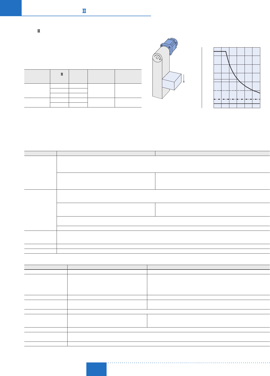
■ Vertical Operation (Gravitational Operation)
The BX
Series provides stable speed control during gravitational
operation.
During vertical operation shown in the figure to the right, normally
an external force causes the motor to rotate and function as a
power generator. If this energy is applied to the driver, an error
will occur. The accessory regeneration unit (sold separately) can
convert regenerative energy into thermal energy for dissipation. Use
the accessory regeneration unit when using the motor for vertical
applications or when braking a large inertial load quickly.
Regeneration Unit
Product Name
BX
Product Name
Rated
Output Power
W (HP)
Continuous
Regenerative Power
W (HP)
Instantaneous
Regenerative Power
W (HP)
EPRC-400P
BXS230 30 (1/25)
100 (1/8) 240 (1/3)BXS460 60 (1/12)
BXS5120 120 (1/6)
RGB100 BXS6200 200 (1/4) 100 (1/8) 800 (1)
BXS6400 400 (1/2)
Install the regeneration unit in the place which has the same heat radiation capability as heat
radiation plate [material: aluminum 350×350 mm (13.8×13.8 in.), 3 mm (0.12 in.) thick].
Regenerative Power
The regenerative power can be estimated using the formula below.
Use the calculated value as a guideline.
Regenerative Power (W) = 0.1047×
T
L
[N·m]×
N
[r/min]
T
L
: Load torque
N
: Speed
W
Load
Gravitational Operation Capability
0
-0.2
-0.4
-0.6
-0.8
-1.0
0 1000 2000 3000
Speed [r/min]
Torque [N·m]
Torque [oz-in]
-1.2
-1.4
BX6200
BX6200
BX5120
BX460
BX230
BX5120
BX460
BX230
BX6400
BX6400
0
-20
-40
-60
-80
-100
-120
-140
-160
-180-
-
-
-
-
-
-
-
-
-
Gravitational operation exceeding the range of continuous regeneration capability will trigger
the built-in thermal protector [150˚C (302˚F)].
Use the electromagnetic brake type for gravitational operation.
■Common Specifications
Item Speed Control Mode Position Control Mode
Input Signals
Photocoupler input Input resistance: 6.6 k
Ω
Operated by internal power supply: 5 VDC
Connectible external power supply: 24 VDC −15+20% 100 mA min.
Sink input/source input Supplied through external wiring
Arbitrary signal assignment to IN0IN8 input (9 points) is possible.
[ ]: Initial setting
[FWD], [RVS] ,[M0], [M1], [M2], M3, [FREE], [STOP], [ALM-RST], TH, TL, S-ON,
HMI, [Not used]
Arbitrary signal assignment to IN0IN8 input (9 points) is possible.
[ ]: Initial setting
[START], [M0], [M1], [M2], M3, [FREE], [STOP], [ALM-RST], [HOME], [HOMES], TH, SSTART, MS0,
MS1, MS2, MS3, MS4, MS5, FWD, RVS, +JOG, −JOG, S-ON, P-PRESET, TL, HMI, Not used
Output Signals
Photocoupler and Open-Collector Output
External power supply: 4.530 VDC 100 mA max.
Sink output/source output Supplied through external wiring
Arbitrary signal assignment to OUT0OUT2 output (3 points) is possible.
[ ]: Initial setting
[ALM], [WNG], [MOVE], END, TLC, VA, ZSG
Arbitrary signal assignment to OUT0OUT2 output (3 points) is possible.
[ ]: Initial setting
[ALM], WNG, MOVE, [READY], [HOME-P], END, TLC, VA, ZSG
Transistor and open-collector output
External power supply: 4.530 VDC 20 mA max.
ASG, BSG 500 pulses/rotation
Protective
Function
When the following protective functions are activated, the ALM output turns OFF and the motor will stop. The alarm code will be displayed on the control panel at the same time
.
Overfl ow, overcurrent, overvoltage, undervoltage, overload, overspeed, EEPROM error, Initial sensor error, initial operation inhibition, regeneration unit overheat, software
overtravel (Only in position control mode), operating data error
Max. Extension Length Motor and driver distance: 30.4 m (99.7 ft.) (when an accessory connection cable is used)
Time Rating Continuous
■Speed Control Mode Specifications
Item Digital Setting Analog Setting
Speed Control Range 24000 r/min (Set in 1 r/min increments) 304000 r/min
Speed Setting Method
Select one of the following methods:
· Control panel · MEXE02✽1 · OPX-2A (accessory)
Select one of the following setting methods:
(Operating data No. 215 are digital settings only)
· Operating data No. 0: Internal speed potentiometer (SPEED)
· Operating data No. 1: PAVR-20KZ (accessory) or external DC voltage
External analog setting with 010 VDC✽2 (1 mA min.)
Acceleration/Deceleration Time 0.00030.00 s (rated speed, no load) 0.130 s (rated speed, no load)
Acceleration/Deceleration Time
Setting Method
Select one of the following methods: (Individual settings)
· Control panel · MEXE02✽1 · OPX-2A (accessory)
Acceleration time/deceleration time are common to operating data No. 0 and No. 1
· Acceleration time potentiometer (ACC) ∙ Deceleration time potentiometer (DEC)
Torque Limiting Setting Range 0250%
Torque Limiting Setting Methods
Select one of the following methods:
· Control panel · MEXE02✽1 · OPX-2A (accessory)
Torque limiting is common to all operating data
· PAVR-20KZ (accessory) or external DC voltage
External analog setting with 010 VDC✽2 (1 mA min).
Operation Data Setting Number 16 Points
Operation during Motor Standstill Operations can be selected when the motor is at standstill.
· Motor non-excitation (initial setting) / · Position holding by servo control (motor excitation)
Other Operations JOG operation, test operation, teaching (excluding MEXE02✽1)
✽1 The data setting software MEXE02 can be downloaded from the website. When using MEXE02, the data setting software communication cable CC05IF-USB (accessory) is needed.
✽2 The max. voltage can be arbitrarily changed with the parameters. Example: 05 VDC

D-95
Brushless Motors/AC Speed Control Motors
D-95
Brushless
Motors
Overview,
Product
Series
AC Input
BMU
AC Input
BLE
AC Input
BLF
AC Input
BX
DC Input
BLH
DSC
BHF
AC Speed
Control
Motors
Accessories
Installation
CAD Data
Manuals www.orientalmotor.com Technical
Support TEL: (800) 468-3982
E-mail: techsupport@orientalmotor.com
■Position Control Mode Specifications
Item Digital Setting
Positioning
Operation
Traveling Amount Setting Range −8,388,608+8,388,607 step
Resolution 0.72˚ (500 steps/rotation)
Speed Setting Range 24000 r/min (Set in 1 r/min increments)
Operating Modes Incremental or absolute
Operation Functions Independent, linked, linked 2, sequential, direct
Acceleration/Deceleration Time 0.00030.00 s
(Rated speed, no load)
Torque Limiting Setting Range 0250%
Operation Data Setting Number 16 Points
How to Set Operating Data
Select one of the following methods:
· Control panel · MEXE02✽ · OPX-2A (accessory)
(Torque limiting alone can be done with external analog settings as well)
Other Operations Continuous operation, JOG operation, return-to-home operation, test operation, teaching
✽The data setting software MEXE02 can be downloaded from the website. When using MEXE02, the data setting software communication cable CC05IF-USB (accessory) is needed.
■Torque Limiting Function
The motor's output torque can be limited in speed control mode and position control mode.
Item Specifi cations
Torque Limiting Setting
Command
Select one of the following methods:
· Digital independent setting: Torque limiting values can be set separately for 16 data sets.
· External analog common setting: A torque limiting value can be set arbitrarily via PAVR-20KZ (accessory) or with external DC voltage (010 VDC✽1).
The same torque limiting value applies to all operation data.
Torque Limiting Setting Range✽2
Assuming that the rated torque of the motor is 100%, torque limiting values can be set in one of the following ranges:
· Digital Setting: 0250% (set in 1% increments)
· External Analog Setting: 0250% with PAVR-20KZ (accessory) or external DC voltage (010 VDC✽1)
✽1 The max. voltage can be arbitrarily changed with the parameters. Example: 05 VDC
✽2 Do not add a load that exceeds the max. instantaneous torque.
Note
An error up to a maximum of approximately ±10% (at rated torque and rated speed) may occur between the setting value and generated torque due to the setting speed, power supply voltage and motor cable
extension length.
■General Specifications
Item Motor Driver
Insulation Resistance
100 M
Ω
or more when 500 VDC megger is applied between the windings and
the case after continuous operation under normal ambient temperature and
humidity.
(Except for the encoder)
100 M
Ω
or more when 500 VDC megger is applied between the power
supply terminal and the protective earth terminal, and between the power
supply terminal and the I/O signal terminal after continuous operation
under normal ambient temperature and humidity.
Dielectric Strength
Sufficient to withstand 1.5 kVAC at 50 Hz applied between the windings
and the case for 1 minute after continuous operation under normal ambient
temperature and humidity.
(Except for the encoder)
Sufficient to withstand 1.5 kVAC at 50 Hz applied between the power
supply terminal and the protective earth terminal for 1 minute, and
1.5 kVAC at 50 Hz applied between the power supply terminal and the
I/O signal terminal for 1 minute after continuous operation under normal
ambient temperature and humidity
.
Temperature Rise
Temperature rise of the windings is 50˚C (90˚F) max. and that of the case
surface is 40˚C (72˚F) max.✽1, measured by the thermocouple method after
rated continuous operation under normal ambient temperature and humidity.
Temperature rise of the heat sink is 50˚C (90˚F) max. measured by the
thermocouple method after rated continuous operation under normal
ambient temperature and humidity. [60˚C (108˚F) max. when 200 W (1/4 HP)
and 400 W (1/2 HP) types are installed in contact with each other]
Operating
Environment✽2
Ambient Temperature 050˚C (+32+122˚F) (non-freezing)
0+50˚C (+32+122˚F) (non-freezing)✽2
0+40˚C (+32+72˚F) when 200 W (1/4 HP) and 400 W (1/2 HP) types
are installed in contact with each other
Ambient Humidity 85% max. (non-condensing)
Altitude Max. of 1000 m (3300 ft.) above sea level
Atmosphere No corrosive gases or dust. Cannot be used in a radioactive area, magnetic field, vacuum, or other special environments.
Vibration Must not be subjected to continuous vibration or excessive shock Conforms to JIS C 60068-2-6, "Sine-wave vibration test method"
Frequency range: 1055 Hz Half amplitude: 0.15 mm (0.006 in.) Sweep direction: 3 directions (X, Y, Z) Number of sweeps: 20 times
Storage
Condition✽3
Ambient Temperature −20+60˚C (−4+140˚F) (non-freezing) −25+70˚C (−13+158˚F) (non-freezing)
Ambient Humidity 85% max. (non-condensing)
Altitude Max. of 3000 m (10000 ft.) above sea level
Heat-Resistant Class UL/CSA Standards: 105 (A), EN Standards: 120 (E) −
Degree of Protection IP54 (Excluding the installation surface of the round shaft type and connectors) IP20
✽1 For round shaft types, please attach to the heat radiation plate (material: aluminum) of the following sizes to maintain a maximum motor case temperature of 90˚C (194˚F).
30W (1/25 HP): 115×115 mm (4.53×4.53 in.), 5 mm (0.20 in.) thick 60W (1/12 HP): 135×135 mm (5.31×5.31 in.), 5 mm (0.20 in.) thick
120W (1/6 HP): 165×165 mm (6.50×6.50 in.), 5 mm (0.20 in.) thick 200W (1/4 HP): 200×200 mm (7.87×7.87 in.), 5 mm (0.20 in.) thick
400W (1/2 HP): 250×250 mm (9.84×9.84 in.), 6 mm (0.24 in.) thick
✽2 Attach the driver to a location that has the same heat radiation capability as an aluminum metal plate.
Single installed 200×200 mm (7.87×7.87 in.), 2 mm (0.079 in.) thick
Installed in contact 350×350 mm (13.8×13.8 in.), 2 mm (0.079 in.) thick
200 W (1/4 HP) and 400 W (1/2 HP) types: When using driver mounting brackets and DIN rail mounting brackets (accessory), the load factor must be 90% or less.
✽3 The storage condition applies to short periods such as the period during transport.
Note
Do not measure insulation resistance or perform a dielectric strength test while the motor and driver are connected.
D-96
D-96 Brushless Motors/BX
Series
ORIENTAL MOTOR GENERAL CATALOG
2015/2016 Page
Features D-86 / System Configuration D-89 / Product Line D-90 / Specifications D-92 / Characteristics D-92
Dimensions D-99 / Connection and Operation D-112 / Motor and Driver Combinations D-115
■ Permissible Torque on Combination Types
Combination Type with a Parallel Shaft Gearhead Unit: N·m (lb-in)
Product Name Gear Ratio
Motor Shaft Speed 5 10 15 20 30 50 100 200
BXS230
At 23000 r/min 0.45 0.9 1.4 1.8 2.6 4.3 6 6
(3.9) (7.9) (12.3) (15.9) (23) (38) (53) (53)
At 4000 r/min 0.34 0.68 1 1.4 1.9 3.2 5.4 5.4
(3) (6) (8.8) (12.3) (16.8) (28) (47) (47)
BXS460
At 23000 r/min 0.9 1.8 2.7 3.6 5.2 8.6 16 16
(7.9) (15.9) (23) (31) (46) (76) (141) (141)
At 4000 r/min 0.68 1.4 2 2.7 3.9 6.5 12.9 14
(6) (12.3) (17.7) (23) (34) (57) (114) (123)
BXS5120
At 23000 r/min 1.8 3.6 5.4 7.2 10.3 17.2 30 30
(15.9) (31) (47) (63) (91) (152) (260) (260)
At 4000 r/min 1.4 2.7 4.1 5.4 7.7 12.9 25.8 27
(12.3) (23) (36) (47) (68) (114) (220) (230)
BXS6200
At 23000 r/min 2.9 5.9 8.8 11.7 16.8 28 52.7 70
(25) (52) (77) (103) (148) (240) (460) (610)
At 4000 r/min 2.2 4.3 6.5 8.6 12.4 20.6 38.9 63
(19.4) (38) (57) (76) (109) (182) (340) (550)
BXS6400
At 23000 r/min 5.9 11.7 17.6 23.4 33.5 55.9 70 70
(52) (103) (155) (200) (290) (490) (610) (610)
At 4000 r/min 4.3 8.6 12.8 17.1 24.5 40.9 63 63
(38) (76) (113) (151) (210) (360) (550) (550)
A colored background indicates gear shaft rotation in the same direction as the motor shaft. Others rotate in the opposite direction.
Combination Type with a Hollow Shaft Flat Gearhead Unit: N·m (lb-in)
Product Name Gear Ratio
Motor Shaft Speed 5 10 15 20 30 50 100 200
BXS230
At 23000 r/min 0.4 0.85 1.3 1.7 2.6 4.3 8.5 17
(3.5) (7.5) (11.5) (15) (23) (38) (75) (150)
At 4000 r/min 0.3 0.64 0.96 1.3 1.9 3.2 6.4 12.8
(2.6) (5.6) (8.4) (11.5) (16.8) (28) (56) (113)
BXS460
At 23000 r/min 0.85 1.7 2.6 3.4 5.1 8.5 17 34
(7.5) (15) (23) (30) (45) (75) (150) (300)
At 4000 r/min 0.64 1.3 1.9 2.6 3.8 6.4 12.8 25.5
(5.6) (11.5) (16.8) (23) (33) (56) (113) (220)
BXS5120
At 23000 r/min 1.7 3.4 5.1 6.8 10.2 17 34 68
(15) (30) (45) (60) (90) (150) (300) (600)
At 4000 r/min 1.3 2.6 3.8 5.1 7.7 12.8 25.5 51
(11.5) (23) (33) (45) (68) (113) (220) (450)
BXS6200
At 23000 r/min − 5.5 8.3 11.1 16.6 27.6 55.3 −
− (48) (73) (98) (146) (240) (480) −
At 4000 r/min − 4.1 6.1 8.2 12.2 20.4 40.8 −
− (36) (53) (72) (107) (180) (360) −
BXS6400
At 23000 r/min 5.5 11.1 16.6 22.1 33.2 55.3 110 −
(48) (98) (146) (195) (290) (480) (970) −
At 4000 r/min 4 8.1 12.1 16.2 24.2 40.4 80.8 −
(35) (71) (107) (143) (210) (350) (710) −
The flat gearhead rotates in the opposite direction to the motor when viewed from the front face of the gearhead. It rotates in the same direction as the motor when viewed from the rear (motor installation surface)
of the gearhead.
Rotation direction of hollow shaft flat gearhead ➜ Page D-195
■Output Shaft Speed of Combination Types Unit: r/min
Gear Ratio
Motor Shaft Speed 5 10 15 20 30 50 100 200
2 r/min 0.4 0.2 0.13 0.1 0.07 0.04 0.02 0.01
30 r/min 6 3 2 1.5 1 0.6 0.3 0.15
3000 r/min 600 300 200 150 100 60 30 15
4000 r/min 800 400 267 200 133 80 40 20
D-97
Brushless Motors/AC Speed Control Motors
D-97
Brushless
Motors
Overview,
Product
Series
AC Input
BMU
AC Input
BLE
AC Input
BLF
AC Input
BX
DC Input
BLH
DSC
BHF
AC Speed
Control
Motors
Accessories
Installation
CAD Data
Manuals www.orientalmotor.com Technical
Support TEL: (800) 468-3982
E-mail: techsupport@orientalmotor.com
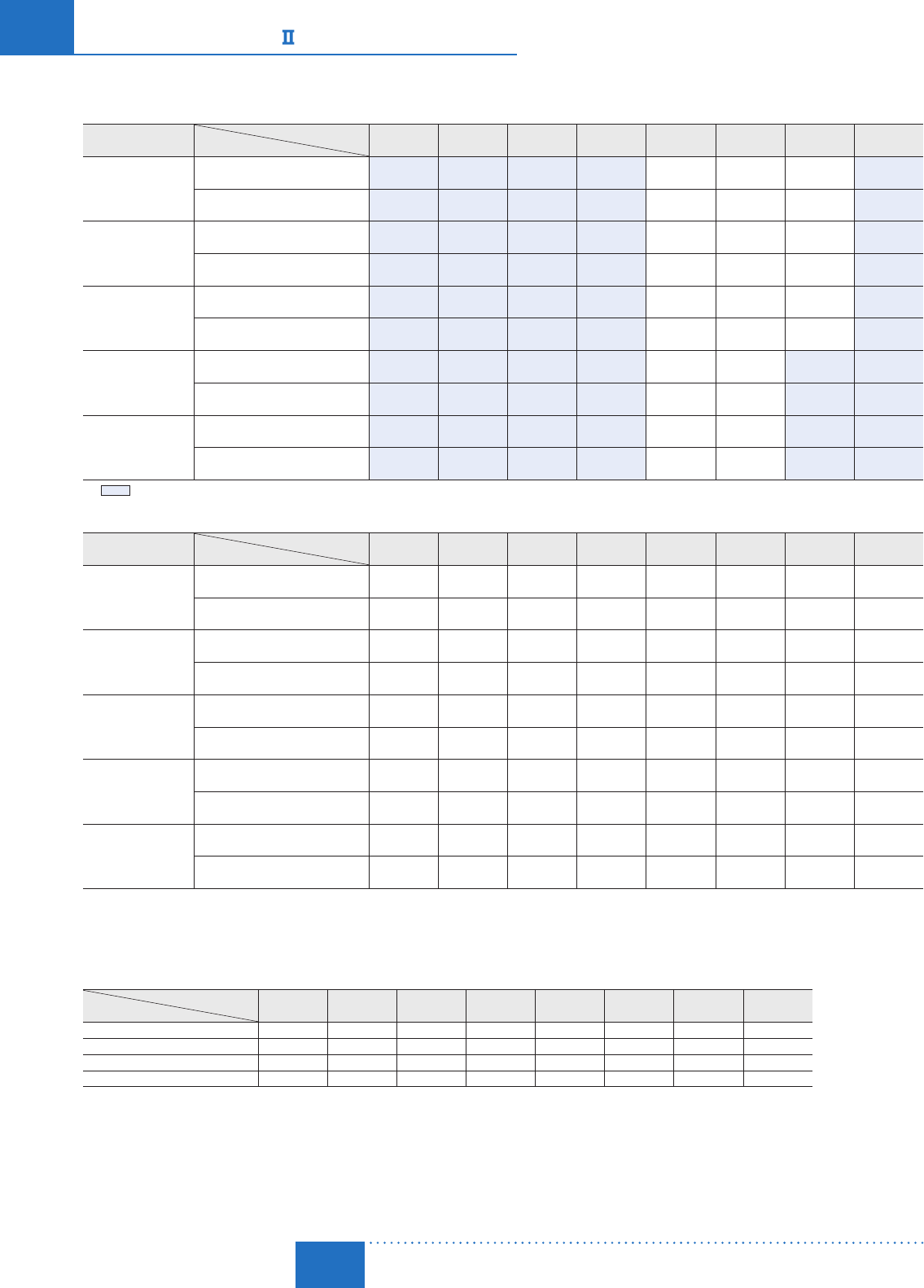
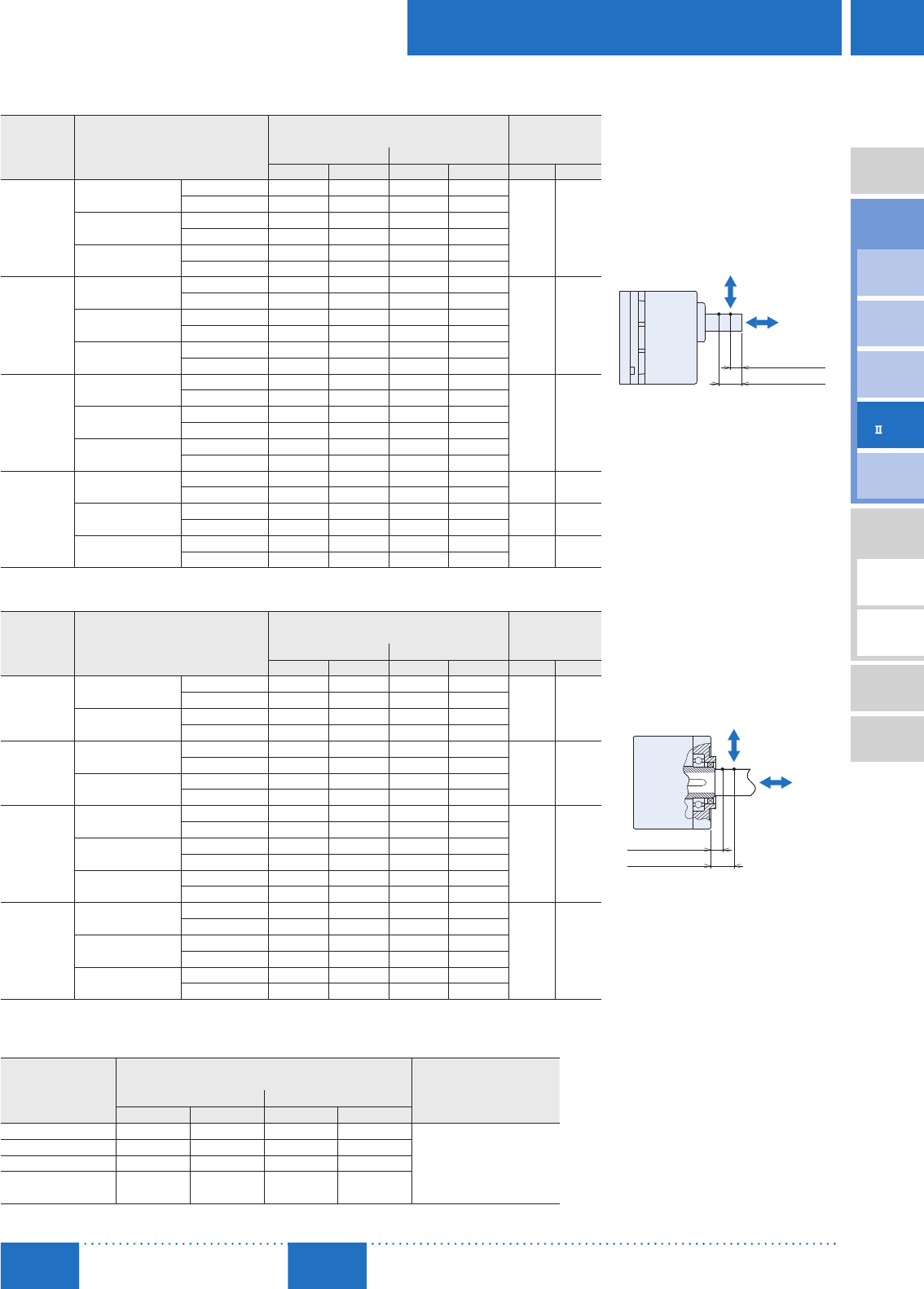
■Permissible Radial Load and Permissible Axial Load
Combination Type with a Parallel Shaft Gearhead
Product Name Gear Ratio
Permissible Radial Load Permissible
Axial Load
Distance from Output Shaft End
10 mm (0.39 in.) 20 mm (0.79 in.)
N lb. N lb. N lb.
BXS230
5At 23000 r/min 100 22 150 33
40 9
At 4000 r/min 90 20 110 24
10, 15, 20 At 23000 r/min 150 33 200 45
At 4000 r/min 130 29 170 38
30, 50, 100, 200 At 23000 r/min 200 45 300 67
At 4000 r/min 180 40 230 51
BXS460
5At 23000 r/min 200 45 250 56
100 22
At 4000 r/min 180 40 220 49
10, 15, 20 At 23000 r/min 300 67 350 78
At 4000 r/min 270 60 330 74
30, 50, 100, 200 At 23000 r/min 450 101 550 123
At 4000 r/min 420 94 500 112
BXS5120
5At 23000 r/min 300 67 400 90
150 33
At 4000 r/min 230 51 300 67
10, 15, 20 At 23000 r/min 400 90 500 112
At 4000 r/min 370 83 430 96
30, 50, 100, 200 At 23000 r/min 500 112 650 146
At 4000 r/min 450 101 550 123
BXS6200
BXS6400
5, 10, 15, 20 At 23000 r/min 550 123 800 180 200 45
At 4000 r/min 500 112 700 157
30, 50 At 23000 r/min 1000 220 1250 280 300 67
At 4000 r/min 900 200 1100 240
100, 200 At 23000 r/min 1400 310 1700 380 400 90
At 4000 r/min 1200 270 1400 310
■Combination Type with a Hollow Shaft Flat Gearhead
Product Name Gear Ratio
Permissible Radial Load Permissible
Axial Load
Distance from Installation Surface of Gearhead
10 mm (0.39 in.) 20 mm (0.79 in.)
N lb. N lb. N lb.
BXS230
5, 10 At 23000 r/min 450 101 370 83
200 45
At 4000 r/min 410 92 330 74
15, 20, 30, 50,
100, 200
At 23000 r/min 500 112 400 90
At 4000 r/min 460 103 370 83
BXS460
5, 10 At 23000 r/min 800 180 660 148
400 90
At 4000 r/min 730 164 600 135
15, 20, 30, 50,
100, 200
At 23000 r/min 1200 270 1000 220
At 4000 r/min 1100 240 910 200
BXS5120
5, 10 At 23000 r/min 900 200 770 173
500 112
At 4000 r/min 820 184 700 157
15, 20 At 23000 r/min 1300 290 1110 240
At 4000 r/min 1200 270 1020 220
30, 50, 100, 200 At 23000 r/min 1500 330 1280 280
At 4000 r/min 1400 310 1200 270
BXS6200
BXS6400
5✽, 10 At 23000 r/min 1230 270 1070 240
800 180
At 4000 r/min 1130 250 990 220
15, 20 At 23000 r/min 1680 370 1470 330
At 4000 r/min 1550 340 1360 300
30, 50, 100 At 23000 r/min 2040 450 1780 400
At 4000 r/min 1900 420 1660 370
✽Limited to 400W (1/2 HP) type.
The permissible radial load can also be calculated with a formula. Calculation of permissible radial load ➜ Page D-194
Round Shaft Type
Product Name
Permissible Radial Load
Permissible Axial Load
Distance from Output Shaft End
10 mm (0.39 in.) 20 mm (0.79 in.)
N lb. N lb.
BXS230 87.2 19 107 24
Half of motor mass or less
BXS460 117 26 137 30
BXS5120 156 35 176 39
BXS6200
BXS6400 197 44 221 49
10 mm (0.39 in.)
20 mm (0.79 in.)
Distance from Output Shaft End
Axial Load
Radial Load
Axial Load
Radial Load
10 mm (0.39 in.)
20 mm (0.79 in.)
Distance from Installation Surface

D-98
D-98 Brushless Motors/BX
Series
ORIENTAL MOTOR GENERAL CATALOG
2015/2016 Page
Features D-86 / System Configuration D-89 / Product Line D-90 / Specifications D-92 / Characteristics D-92
Dimensions D-99 / Connection and Operation D-112 / Motor and Driver Combinations D-115
■ Permissible Inertia J of Combination Types
Combination Type with a Parallel Shaft Gearhead Unit: ×10-4kg·m2 (oz-in2)
Gear Ratio
Product Name 5 10 15 20 30 50 100 200
BXS230
12 50 110 200 370 920 2500 5000
(66) (270) (600) (1090) (2000) (5000) (13700) (27000)
When instantaneous stop or instantaneous
bi-directional operation is performed✽
1.55 6.2 14 24.8 55.8 155 155 155
(8.5) (34) (77) (136) (310) (850) (850) (850)
BXS460
22 95 220 350 800 2200 6200 12000
(120) (520) (1200) (1910) (4400) (12000) (34000) (66000)
When instantaneous stop or instantaneous
bi-directional operation is performed✽
5.5 22 49.5 88 198 550 550 550
(30) (120) (270) (480) (1080) (3000) (3000) (3000)
BXS5120
45 190 420 700 1600 4500 12000 25000
(250) (1040) (2300) (3800) (8800) (25000) (66000) (137000)
When instantaneous stop or instantaneous
bi-directional operation is performed✽
25 100 225 400 900 2500 2500 2500
(137) (550) (1230) (2200) (4900) (13700) (13700) (13700)
BXS6200
BXS6400
100 460 1000 1700 3900 9300 18000 37000
(550) (2500) (5500) (9300) (21000) (51000) (98000) (200000)
When instantaneous stop or instantaneous
bi-directional operation is performed✽
50 200 450 800 1800 5000 5000 5000
(270) (1090) (2500) (4400) (9800) (27000) (27000) (27000)
✽It is also applicable when digitally setting the deceleration time to below 0.1 second.
Combination Type with a Hollow Shaft Flat Gearhead Unit: ×10-4kg·m2 (oz-in2)
Gear Ratio
Product Name 5 10 15 20 30 50 100 200
BXS230
12 50 110 200 370 920 2500 5000
(66) (270) (600) (1090) (2000) (5000) (13700) (27000)
When instantaneous stop or instantaneous
bi-directional operation is performed✽
1.55 6.2 14 24.8 55.8 155 155 155
(8.5) (34) (77) (136) (310) (850) (850) (850)
BXS460
22 95 220 350 800 2200 6200 12000
(120) (520) (1200) (1910) (4400) (12000) (34000) (66000)
When instantaneous stop or instantaneous
bi-directional operation is performed✽
5.5 22 49.5 88 198 550 550 550
(30) (120) (270) (480) (1080) (3000) (3000) (3000)
BXS5120
45 190 420 700 1600 4500 12000 25000
(250) (1040) (2300) (3800) (8800) (25000) (66000) (137000)
When instantaneous stop or instantaneous
bi-directional operation is performed✽
25 100 225 400 900 2500 2500 2500
(137) (550) (1230) (2200) (4900) (13700) (13700) (13700)
BXS6200
− 460 1000 1700 3900 9300 18000 −
− (2500) (5500) (9300) (21000) (51000) (98000) −
When instantaneous stop or instantaneous
bi-directional operation is performed✽
− 200 450 800 1800 5000 5000 −
− (1090) (2500) (4400) (9800) (27000) (27000) −
BXS6400
100 460 1000 1700 3900 9300 18000 −
(550) (2500) (5500) (9300) (21000) (51000) (98000) −
When instantaneous stop or instantaneous
bi-directional operation is performed✽
50 200 450 800 1800 5000 5000 −
(270) (1090) (2500) (4400) (9800) (27000) (27000) −
✽It is also applicable when digitally setting the deceleration time to below 0.1 second.
D-99
Brushless Motors/AC Speed Control Motors
D-99
Brushless
Motors
Overview,
Product
Series
AC Input
BMU
AC Input
BLE
AC Input
BLF
AC Input
BX
DC Input
BLH
DSC
BHF
AC Speed
Control
Motors
Accessories
Installation
CAD Data
Manuals www.orientalmotor.com Technical
Support TEL: (800) 468-3982
E-mail: techsupport@orientalmotor.com
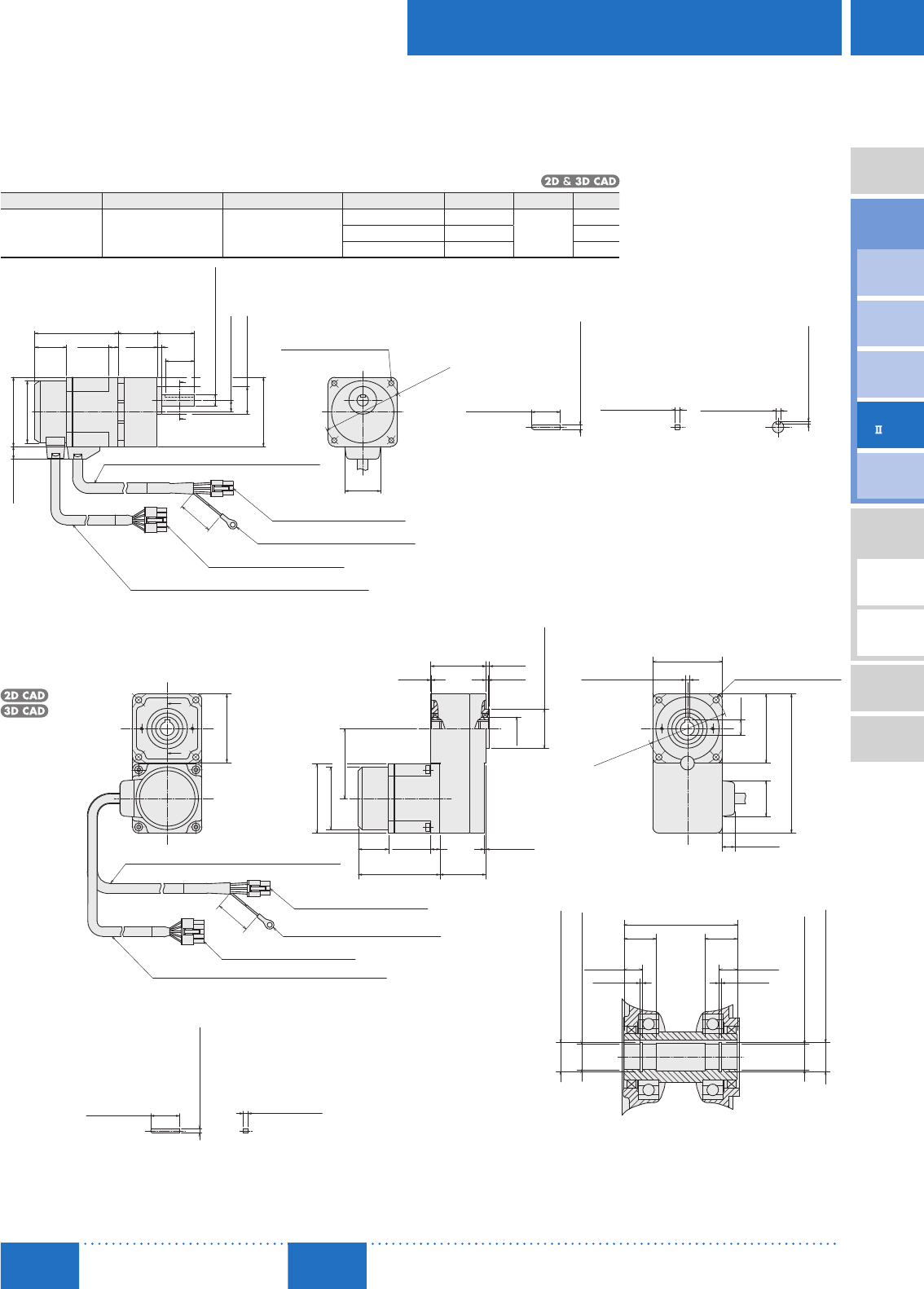
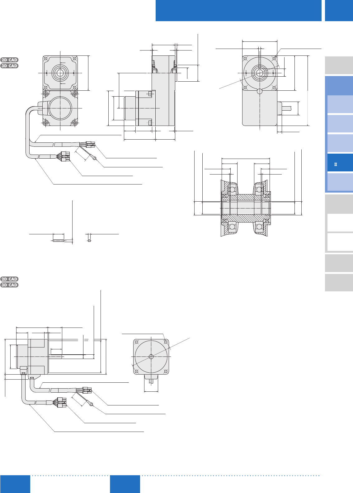
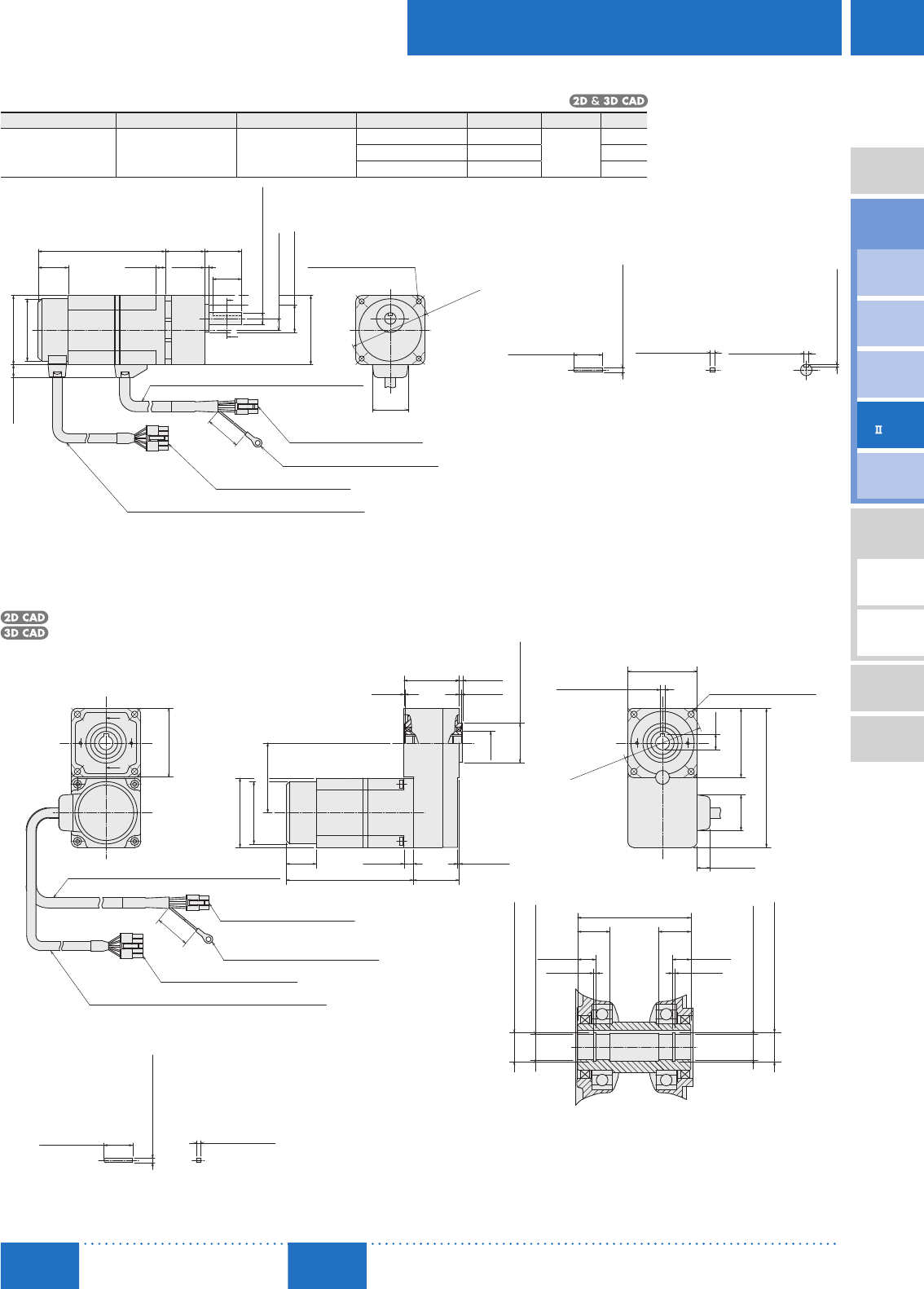
■ Dimensions (Unit mm (in.))
Installation screws are included with the combination type. Dimensions for installation screws ➜ Page D-194
A number indicating the gear ratio is entered where the box □ is located within the product name.
Standard Type 30 W (1/25 HP)
Motor/Parallel Shaft Gearhead
Product Name Motor Product Name Gearhead Product Name Gear Ratio L Mass kg (lb.) 2D CAD
BXS230A-□S-3
BXS230C-□S-3 BXM230-GFS GFS2G□
520 34 (1.34) 1.2
(2.6)
C147A
30100 38 (1.50) C147B
200 43 (1.69) C147C
A
A
60 (2.36)
11 (0.43)
ϕ24 (ϕ0.94)
25
4
L
ϕ54 (ϕ2.13)
200
8
70.5 (2.78)
26
32±1
10±0.5 (0.39±0.02)
□60
(□2.36)
Encoder Cable ϕ8 (ϕ0.31), 400 mm (16 in.) Length
Housing: 5557-10R (MOLEX)
Round Terminal: SRA-51T-4 (JST)
Housing: 5557-06R (MOLEX)
4×ϕ4.5 (ϕ0.177) Thru
ϕ
70
±
0.5
(ϕ
2.76
±0.02)
31
(1.02)(
0.31)
(0.98)
(8)
(1.22)
0
0
ϕ10−0.015
(
ϕ0.3937−0.0006
)
(0.16)
(1.26
±0.04
)
Motor Cable ϕ9 (ϕ0.35), 400 mm (16 in.) Length
25±0.2 4−0.03
0 4 0
+0.040
+0.1
A – A
◇Key and Key Slot (Included)
4−0.03
(
0.1575−0.0012
)
00
(0.984±0.008)
(
0.1575−0.0012
)
0
(
0.1575 0
)
+0.0016
2.5 0
(
0.098 0
)
+0.004
Motor/Hollow Shaft Flat Gearhead
BXS230A-□FR-3, BXS230C-□FR-3
Motor: BXM230-GFS
Gearhead: GFS2G□FR
Mass: 1.5 kg (3.3 lb.)
C195 A
A
200
ϕ54 (ϕ2.13)
(ϕ
0.79
)
60 (2.36)
26
70.5
59.5 (2.34)
60.5 (2.38)
0.8 2 (0.08)
3 (0.12)
47.8 (1.88)
ϕ20
1.5 (0.06)
8 (0.31)
39.8
60 (2.36)
13.8
60 (2.36)
31
(
0.54
)
120.5 (4.74)
Motor Cable ϕ9 (ϕ0.35), 400 mm (16 in.) Length
Housing: 5557-10R (MOLEX)
Encoder Cable ϕ8 (ϕ0.31), 400 mm (16 in.) Length
Housing: 5557-06R (MOLEX)
Round Terminal: SRA-51T-4 (JST)
ϕ34−0.039
0
4×ϕ5.5 (ϕ0.217) Thru
11(0.43)
14
49 (1.93)
14
8 (0.31)8 (0.31)
A – A
◇Key (Included)
(8)
(1.02)
(2.78)(
1.57)
(0.03)
0
(
ϕ1.3386−0.0015
)
ϕ
70
±0.5
(ϕ
2.76
±
0.02
)
4 0
+0.040
(
0.1575 0
)
+0.0016
(1.22)
25±0.2
4−0.03
(
0.1575−0.0012
)
00
(0.984±0.008)
4−0.03
0
(
0.1575−0.0012
)
0
(0.05)
(0.55)(0.55)
(0.05)
1.15 1.15
ϕ12.5 0
(
ϕ0.4921 0
)
+0.11 +0.0043
+0.0011
+0.027
ϕ12 0
(
ϕ0.4724 0
)
ϕ12.5 0
(
ϕ0.4921 0
)
+0.11 +0.0043
+0.0011
+0.027
ϕ12 0
(
ϕ0.4724 0
)
D-100
D-100 Brushless Motors/BX
Series
ORIENTAL MOTOR GENERAL CATALOG
2015/2016 Page
Features D-86 / System Configuration D-89 / Product Line D-90 / Specifications D-92 / Characteristics D-92
Dimensions D-99 / Connection and Operation D-112 / Motor and Driver Combinations D-115
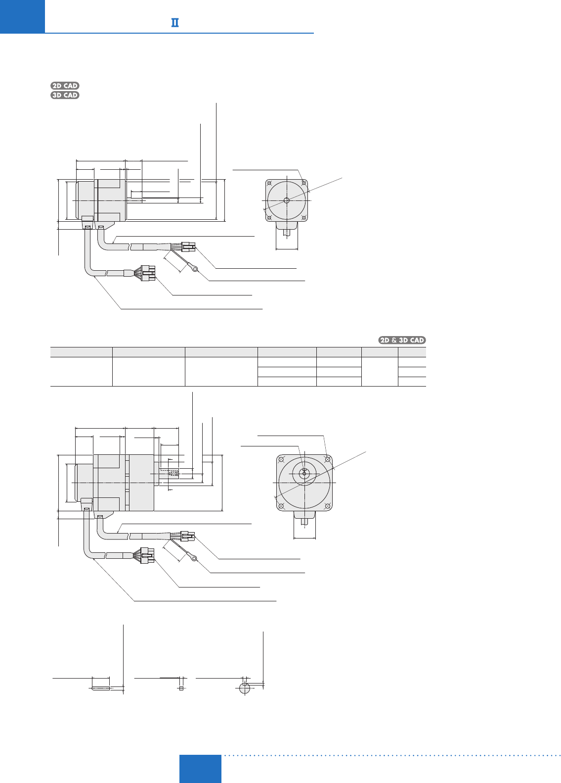
Round Shaft Type
BXS230A-A-3, BXS230C-A-3
Motor: BXM230-A2
Mass: 0.7 kg (1.5 lb.)
C150
226
70.5 (2.78)
60 (2.36)
11 (0.43)
7.5 (0.30)
16 (0.63)
31
(1.22)
200
24±1 (0.94±0.04)
□60
ϕ54 (ϕ2.13)
Motor Cable ϕ9 (ϕ0.35), 400 mm (16 in.) Length
Housing: 5557-10R (MOLEX)
Housing: 5557-06R (MOLEX)
Round Terminal: SRA-51T-4 (JST)
4×ϕ4.5 (ϕ0.177) Thru
(1.02)
8
(0.31)
(
0.08
)
ϕ8−0.015
(
ϕ0.3150−0.0006
)
00
0
0
ϕ54−0.030
(
ϕ2.1260−0.0012
)
(□2.36)
(8)
Encoder Cable ϕ8 (ϕ0.31), 400 mm (16 in.) Length
ϕ
70
±0.5
(
ϕ2.76
±
0.02
)
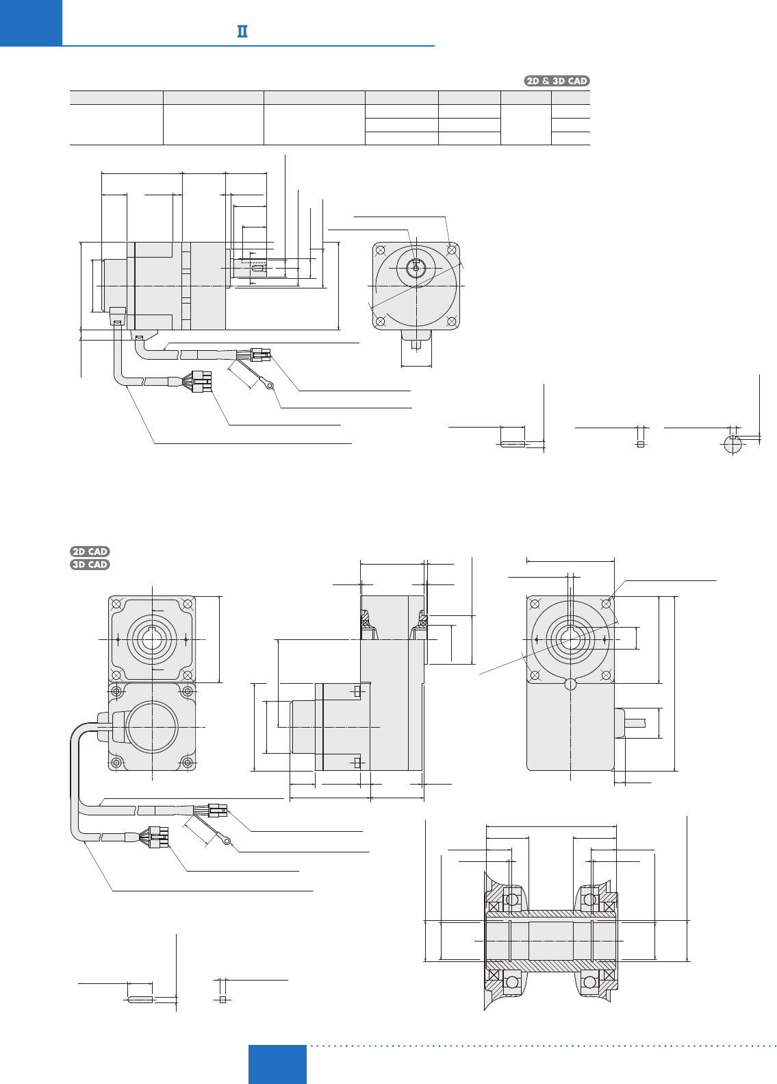
Standard Type 60 W (1/12 HP)
Motor/Parallel Shaft Gearhead
Product Name Motor Product Name Gearhead Product Name Gear Ratio L Mass kg (lb.) 2D CAD
BXS460A-□S-3
BXS460C-□S-3 BXM460-GFS GFS4G□
520 41 (1.61) 2.0
(4.4)
C148A
30100 46 (1.81) C148B
200 51 (2.01) C148C
A
A
80 (3.15)
11 (0.43)
L
ϕ54 (ϕ2.13)
26
71.5 (2.81)
725
35±1
Encoder Cable ϕ8 (ϕ0.31), 400 mm (16 in.) Length
0
0
ϕ15−0.018
(
ϕ0.5906−0.0007
)
13±0.5 (0.51±0.02)
ϕ34 (ϕ1.34)
□80
(□3.15)
Housing: 5557-10R (MOLEX)
Round Terminal: SRA-51T-4 (JST)
Housing: 5557-06R (MOLEX)
Motor Cable ϕ9 (ϕ0.35), 400 mm (16 in.) Length
4×ϕ6.5 (ϕ0.256) Thru
M5×10 (0.39) Deep
A – A
◇Key and Key Slot (Included)
8
(1.02)(
0.31)
(1.38
±
0.04)
(0.28)
(0.98)
31
(1.22)
ϕ
94
±
0.5
(ϕ
3.70
±0.02)
5−0.03
0
(
0.1969−0.0012
)
0
5 0
+0.040
(
0.1969 0
)
+0.0016
25±0.2
(0.984±0.008)
5−0.03
(
0.1969−0.0012
)
00
+0.1
3 0
(
0.118 0
)
+0.004
200
(8)
D-101
Brushless Motors/AC Speed Control Motors
D-101
Brushless
Motors
Overview,
Product
Series
AC Input
BMU
AC Input
BLE
AC Input
BLF
AC Input
BX
DC Input
BLH
DSC
BHF
AC Speed
Control
Motors
Accessories
Installation
CAD Data
Manuals www.orientalmotor.com Technical
Support TEL: (800) 468-3982
E-mail: techsupport@orientalmotor.com
Motor/Hollow Shaft Flat Gearhead
BXS460A-□FR-3, BXS460C-□FR-3
Motor: BXM460-GFS
Gearhead: GFS4G□FR
Mass: 2.6 kg (5.7 lb.)
C196
80 (3.15)
1
53.2 (2.09)
79.5 (3.13)
80 (3.15)
160.5 (6.32)
80.5
(3.17)
A
A
80 (3.15)
Encoder Cable ϕ8 (ϕ0.31), 400 mm (16 in.) Length
Housing: 5557-10R (MOLEX)
Housing: 5557-06R (MOLEX)
ϕ54 (ϕ2.13)
4ϕ6.5 (ϕ0.256) Thru
18
(0.71)
18
(0.71)
55.2 (2.17)
A – A
◇Key (Included)
50.03
0
(
0.19690.0012
)
0
250.2
(0.9840.008)
26
71.5
1.5 (0.06)
8 (0.31)
45.2
(1.02)
(2.81)(
1.78)
3 (0.12)
4 (0.16)
(0.04)
ϕ380.039
0
0
(
ϕ1.49610.0015
)
(ϕ
0.98
)
ϕ25
Motor Cable ϕ9 (ϕ0.35), 400 mm (16 in.) Length
200
(
8
)
17.3
(0.68)
31
(1.22)
5 0
0.040
(
0.1969 0
)
0.0016
11 (0.43)
ϕ
94
0.5
(ϕ
3.70
0.02)
0.0011
0.027
ϕ15 0
(
ϕ0.5906 0
)
ϕ15.7 0
(
ϕ0.6181 0
)
0.11 0.0043
0.0011
0.027
ϕ15 0
(
ϕ0.5906 0
)
10 (0.39)10 (0.39)
(0.05)
1.15
(0.05)
1.15
ϕ15.7 0
(
ϕ0.6181 0
)
0.11 0.0043
50.03
(
0.19690.0012
)
00
Round Terminal: SRA-51T-4 (JST)
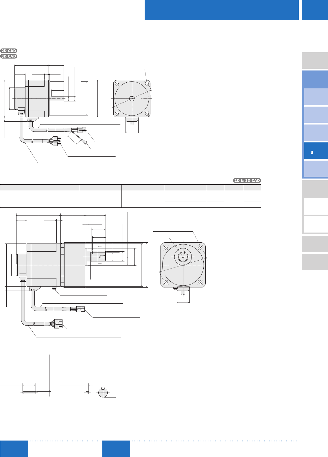
Round Shaft Type
BXS460A-A-3, BXS460C-A-3
Motor: BXM460-A2
Mass: 1.0 kg (2.2 lb.)
C115
9.5 (0.37)
80 (3.15)
ϕ54 (ϕ2.13)
26
71.5 (2.81)
0
0
ϕ73−0.030
(
ϕ2.8740−0.0012
)
ϕ10−0.015
(
ϕ0.3937−0.0006
)
00
□80
(□3.15)
Encoder Cable ϕ8 (ϕ0.31), 400 mm (16 in.) Length
Housing: 5557-10R (MOLEX)
Round Terminal: SRA-51T-4 (JST)
Housing: 5557-06R (MOLEX)
Motor Cable ϕ9 (ϕ0.35), 400 mm (16 in.) Length
4×ϕ6.5 (ϕ0.256) Thru
11 (0.43)
(1.02)
28
(0.31) (0.08)
32±1
(1.26±0.04)
25
(
0.98)
ϕ94
±
0.5
(ϕ
3.70
±0.02)
31
(1.22)
200
(8)
D-102
D-102 Brushless Motors/BX
Series
ORIENTAL MOTOR GENERAL CATALOG
2015/2016 Page
Features D-86 / System Configuration D-89 / Product Line D-90 / Specifications D-92 / Characteristics D-92
Dimensions D-99 / Connection and Operation D-112 / Motor and Driver Combinations D-115
Standard Type 120 W (1/6 HP)
Motor/Parallel Shaft Gearhead
Product Name Motor Product Name Gearhead Product Name Gear Ratio L Mass kg (lb.) 2D CAD
BXS5120A-□S-3
BXS5120C-□S-3 BXM5120-GFS GFS5G□
520 45 (1.77) 3.1
(6.8)
C149A
30100 58 (2.28) C149B
200 64 (2.52) C149C
A
A
L
90 (3.54)
11 (0.43)
5 (0.20)
42±1
ϕ40 (ϕ1.57)
25
(1.22)
ϕ20 (ϕ0.79)
34±0.5
26
83 (3.27)
200
10
ϕ18−0.018
0
18±0.5 (0.71±0.02)
□90
Motor Cable ϕ9 (ϕ0.35), 400 mm (16 in.) Length
Encoder Cable ϕ8 (ϕ0.31), 400 mm (16 in.) Length
Housing: 5557-10R (MOLEX)
Round Terminal: SRA-51T-4 (JST)
Housing: 5557-06R (MOLEX)
M6×12 (0.47) Deep
4×ϕ8.5 (ϕ0.335) Thru
ϕ
104
±
0.5
ϕ54 (ϕ2.13)
25±0.2
6−0.03
0
6−0.03
0 6 0
+0.040
3.5 0
+0.1
A – A
◇Key and Key Slot (Included)
(
ϕ0.138 0
)
+0.004
(
0.2362 0
)
+0.0016
(
0.2362−0.0012
)
0
(
0.2362−0.0012
)
0
(1.02)
(0.39)
(8)
(0.98)
(1.65
±
0.04)
(
1.34
±
0.02
)
(ϕ
4.09
±
0.02
)
(□3.54)
(0.984±0.008)
(
ϕ0.7087−0.0007
)
0
31
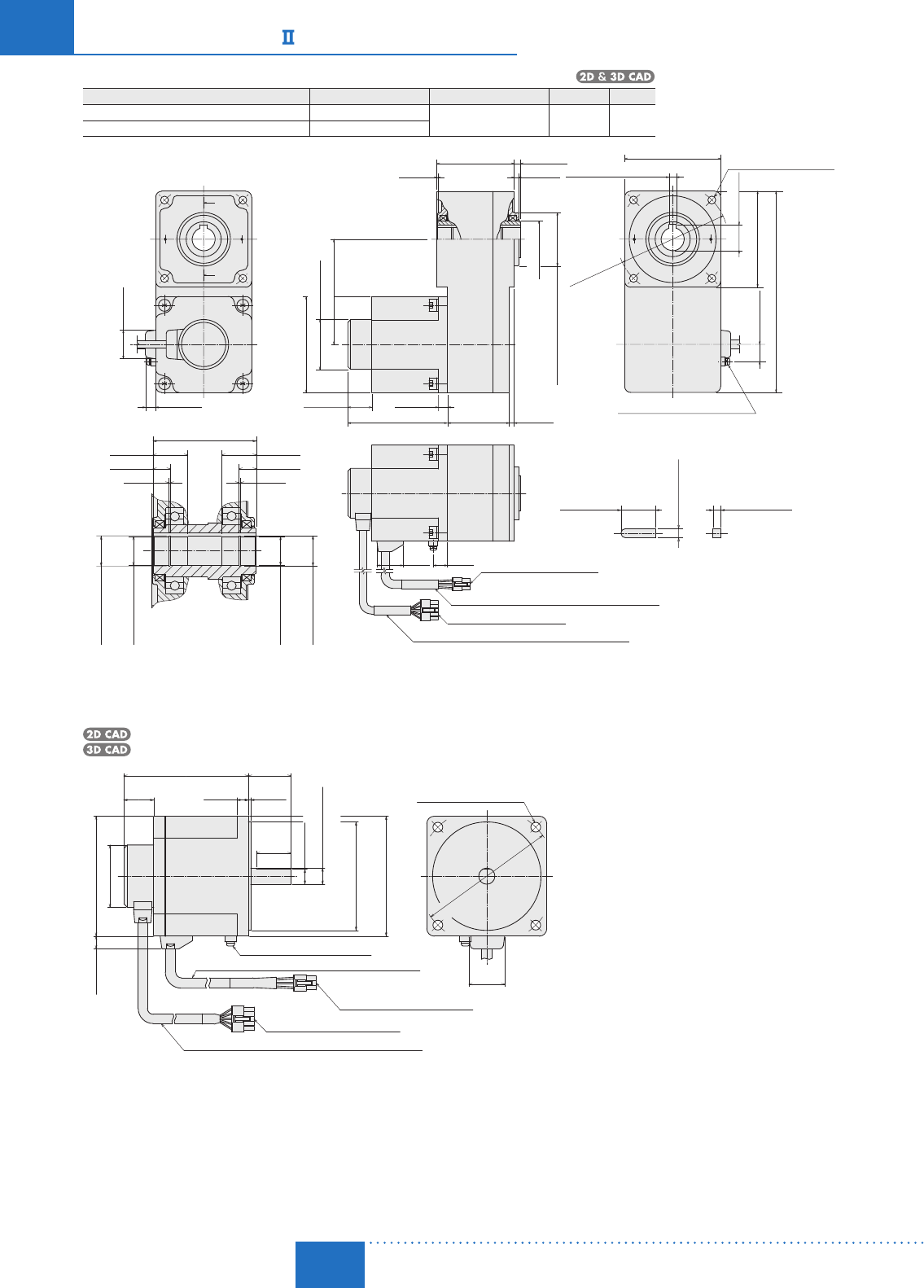
Motor/Hollow Shaft Flat Gearhead
BXS5120A-□FR-3, BXS5120C-□FR-3
Motor: BXM5120-GFS
Gearhead: GFS5G□FR
Mass: 3.8 kg (8.4 lb.)
C197 65.2 4
31
90 (3.54)
55.2
10 2
90 (3.54)
22.8
31
11
90
180
A
A
26
83
90 (3.54)
200
ϕ54
ϕ30
ϕ
104±
0.5
ϕ50
−
0.039
0
4×ϕ8.5 (ϕ0.335) Thru
6 0
+0.040
Housing: 5557-10R (MOLEX)
Round Terminal: SRA-51T-4 (JST)
Housing: 5557-06R (MOLEX)
25±0.2
6−0.03
0
6−0.03
0
67.2 (2.65)
13 (0.51)13 (0.51)
(0.05)(
0.05)
1.15 1.15
22 (0.87)22 (0.87)
ϕ21 0
+0.21
ϕ21 0
+0.21
ϕ20 0
+0.033
ϕ20 0
+0.033
A – A
◇Key (Included)
89 (3.50)
Motor Cable ϕ9 (ϕ0.35), 400 mm (16 in.) Length
Encoder Cable ϕ8 (ϕ0.31), 400 mm (16 in.) Length
(
ϕ0.7874 0
)
+0.0013
(
ϕ0.7874 0
)
+0.0013
(
ϕ0.8268 0
)
+0.0083
(
ϕ0.8268 0
)
+0.0083
(
0.2362 0
)
+0.0016
(
0.2362−0.0012
)
0
(
0.2362−0.0012
)
0
(8)
(0.984
±
0.008)
(ϕ4.09
±
0.02
)
(
ϕ
1.9685
−
0.0015
)
0
(2.57)
(0.04)
(1.02)
(3.27)
(0.39)
(2.17)
(0.08)(0.43)
(1.22)
(7.09)
(3.54)
(
0.90
)
(0.16)
(0.12)
(ϕ1.181)
(ϕ2.13)
D-103
Brushless Motors/AC Speed Control Motors
D-103
Brushless
Motors
Overview,
Product
Series
AC Input
BMU
AC Input
BLE
AC Input
BLF
AC Input
BX
DC Input
BLH
DSC
BHF
AC Speed
Control
Motors
Accessories
Installation
CAD Data
Manuals www.orientalmotor.com Technical
Support TEL: (800) 468-3982
E-mail: techsupport@orientalmotor.com
Round Shaft Type
BXS5120A-A-3, BXS5120C-A-3
Motor: BXM5120-A2
Mass: 1.6 kg (3.5 lb.)
C152
30
11.5 (0.45)
90 (3.54)
11 (0.43)
2
83 (3.27)37±1
200
10
ϕ12
−
0.018
0
ϕ83
−
0.035
0
□90
Motor Cable ϕ9 (ϕ0.35), 400 mm (16 in.) Length
Encoder Cable ϕ8 (ϕ0.31), 400 mm (16 in.) Length
Housing: 5557-10R (MOLEX)
Housing: 5557-06R (MOLEX)
Round Terminal: SRA-51T-4 (JST)
ϕ
104
±
0.5
(0.39)
(1.18)
(0.08)
(1.22)
4×ϕ8.5 (ϕ0.335) Thru
ϕ54 (ϕ2.13)
26
(1.02)
(8)
(
1.46
±0.04)
(
ϕ
4.09
±
0.02
)
(□3.54)
(
ϕ3.2677−0.0014
)
0
(
ϕ0.4724−0.0007
)
0
31
Standard Type 200 W (1/4 HP), 400 W (1/2 HP)
Motor/Parallel Shaft Gearhead
Product Name Motor Product Name Gearhead Product Name Gear Ratio L Mass kg 2D CAD
BXS6200A-□S-3, BXS6200C-□S-3 BXM6200-GFS
GFS6G□
520 60 (2.36) 5.5
(12.1)
C198A
30, 50 72 (2.83) C198B
BXS6400C-□S-3 BXM6400-GFS 100, 200 86 (3.39) C198C
A
A
1026
108 (4.25)
32
35±0.5
50±1
24.5 (0.96)
5 (0.20)
L
20±0.5
□104 (□4.09)
□110 (□4.33)
M6×12 (0.47) Deep
Housing: 5557-10R (MOLEX)
Housing: 5557-06R (MOLEX)
Protective Earth Terminal M4
ϕ22
−
0.021
0
A – A
18.5 0
−
0.1
◇Key and Key Slot (Included)
Motor Cable ϕ9 (ϕ0.35), 400 mm (16 in.) Length
Encoder Cable ϕ8 (ϕ0.31), 400 mm (16 in.) Length
104 (4.09)
11 (0.43)
ϕ54 (ϕ2.13)
(0.39)
(1.26)
(1.02)
(
1.38
±
0.02)
(1.97±0.04)
(
ϕ0.8661−0.0008
)
0
(1.22)
4×ϕ8.5 (ϕ0.335) Thru
ϕ42 (ϕ
1.65
)
ϕ25
(0.79±0.02)
6−0.03
0
(
0.2362−0.0012
)
0
(
0.728−0.004
)
0
6−0.03
0
(1.260±0.008)
(ϕ0.98)
32
±0.2
31
(
0.2362−0.0012
)
0
ϕ120±
0.5
(
ϕ4.72±0.02
)
At the time of shipment, a key is inserted on the gearhead’s shaft.
D-104
D-104 Brushless Motors/BX
Series
ORIENTAL MOTOR GENERAL CATALOG
2015/2016 Page
Features D-86 / System Configuration D-89 / Product Line D-90 / Specifications D-92 / Characteristics D-92
Dimensions D-99 / Connection and Operation D-112 / Motor and Driver Combinations D-115
Motor/Hollow Shaft Flat Gearhead
Product Name Motor Product Name Gearhead Product Name Mass kg (lb.) 2D CAD
BXS6200A-□FR-3, BXS6200C-□FR-3 BXM6200-GFS GFS6G□FR 7.3
(16.1) C257
BXS6400C-□FR-3 BXM6400-GFS
31 (1.22)
11 (0.43)
ϕ54 (ϕ2.13)
114 (4.49)
104 (4.09)
18.5 (0.73)
15.5
28.5
(ϕ4.72
±0.02
)
104 (4.09)
218 (8.58)
28.3 (1.11)
104 (4.09)
5 (0.20)
7 (0.276)
83.5 (3.29)
1 (0.04)
10 (0.39)
26 (1.02)
67 (2.64)5 (0.20)
108 (4.25)
ϕ40 (ϕ1.57)
8 0
−0.036
7 0
−0.09
A
A
ϕ120
±0.5
30±0.2
(1.181±0.008)
(
0.3150−0.0014
)
0
(1.12)(0.61)
(
0.2756−0.0035
)
0
8+0.040
0
(
0.3150 0
)
+0.0016
ϕ58 0
−0.046
(
ϕ2.2835−0.0018
)
0
89.5 (3.52)
1.35
(0.05)
15 (0.59)
30 (1.18)
1.35
(0.05)
15 (0.59)
30 (1.18)
ϕ26.2
+
0.21
(
ϕ1.0315
+
0.0083
)
0
0
ϕ25
+
0.033
(
ϕ0.9843
+
0.0013
)
0
0
A−A
ϕ25
+
0.033
(
ϕ0.9843
+
0.0013
)
0
0
ϕ26.2
+
0.21
(
ϕ1.0315
+
0.0083
)
0
0
4×ϕ8.5 (ϕ0.335) Thru
Key (Included)
Protective Earth Terminal M4
Housing: 5557-06R(MOLEX)
Motor Cable
ϕ
9 (
ϕ0.35
), 400 mm (
16
in.) Length
Housing:
5557-10R(MOLEX)
Encoder Cable
ϕ
8 (
ϕ0.31
), 400 mm (
16
in.) Length
Round Shaft Type
BXS6200A-A-3, BXS6200C-A-3, BXS6400C-A-3
Motor: BXM6200-A, BXM6400-A
Mass: 2.5 kg (5.5 lb.)
C182
2
37±1
13 (0.51)
(□4.09)
30
1026
108 (4.25)
□104
ϕ120
±
0.5
Housing: 5557-10R (MOLEX)
Housing: 5557-06R (MOLEX)
Protective Earth Terminal M4
ϕ14
−
0.018
0
ϕ94
−
0.035
0
104 (4.09)
11 (0.43)
Motor Cable ϕ9 (ϕ0.35), 400 mm (16 in.) Length
Encoder Cable ϕ8 (ϕ0.31), 400 mm (16 in.) Length
(0.39)
(1.18)
(0.08)
(1.22)
ϕ54 (ϕ2.13)
(1.02)
(
1.46
±0.04)
(
ϕ
4.72
±
0.02
)
(
ϕ0.5512−0.0007
)
0
(
ϕ3.7008−0.0014
)
0
4×ϕ8.5 (ϕ0.335) Thru
31
D-105
Brushless Motors/AC Speed Control Motors
D-105
Brushless
Motors
Overview,
Product
Series
AC Input
BMU
AC Input
BLE
AC Input
BLF
AC Input
BX
DC Input
BLH
DSC
BHF
AC Speed
Control
Motors
Accessories
Installation
CAD Data
Manuals www.orientalmotor.com Technical
Support TEL: (800) 468-3982
E-mail: techsupport@orientalmotor.com
Electromagnetic Brake Type 30 W (1/25 HP)
Motor/Parallel Shaft Gearhead
Product Name Motor Product Name Gearhead Product Name Gear Ratio L Mass kg (lb.) 2D CAD
BXS230AM-□S-3
BXS230CM-□S-3 BXM230M-GFS GFS2G□
520 34 (1.34) 1.5
(3.3)
C153A
30100 38 (1.50) C153B
200 43 (1.69) C153C
A
60 (2.36)
ϕ54 (ϕ2.13)
110 (4.33)L
Housing: 5557-10R (MOLEX)
Round Terminal: SRA-51T-4 (JST)
Housing: 5557-06R (MOLEX)
Motor Cable ϕ9 (ϕ0.35), 400 mm (16 in.) Length
11 (0.43)
26
(1.02)
8
(0.31)
4
(0.16)25
32±1
(0.98)
(1.26
±0.04
)
A
0
0
ϕ10−0.015 (ϕ0.3937−0.0006
)
ϕ24 (ϕ0.94)
10±0.5 (0.39±0.02)
□60
(□2.36)
Encoder Cable ϕ8 (ϕ0.31), 400 mm (16 in.) Length
200
(8)
31
(1.22)
ϕ70±
0.5
(
ϕ
2.76
±0.02)
4×ϕ4.5 (ϕ0.177) Thru
25±0.2 4−0.03
0 4 0
+0.040
+0.1
A – A
◇Key and Key Slot (Included)
4−0.03
(
0.1575−0.0012
)
00
(0.984±0.008)
(
0.1575−0.0012
)
0
(
0.1575 0
)
+0.0016
2.5 0
(
0.098 0
)
+0.004
Motor/Hollow Shaft Flat Gearhead
BXS230AM-□FR-3, BXS230CM-□FR-3
Motor: BXM230M-GFS
Gearhead: GFS2G□FR
Mass: 1.8 kg (4.0 lb.)
C199
A
A
110 (4.33)
ϕ54 (ϕ2.13)
60 (2.36)
59.5 (2.34)
60.5 (2.38)
47.8 (1.88)
1.5 (0.06)
60 (2.36)
Encoder Cable ϕ8 (ϕ0.31), 400 mm (16 in.) Length
Housing: 5557-10R (MOLEX)
Round Terminal: SRA-51T-4 (JST)
Housing: 5557-06R (MOLEX)
25±0.2
4−0.03
(
0.1575−0.0012
)
00
(0.984±0.008)
4−0.03
0
(
0.1575−0.0012
)
0
◇Key (Included)
200
(8)
0.8
(0.03)
2 (0.08)
3 (0.12)
ϕ34−0.039
0
0
(
ϕ1.3386−0.0015
)
(ϕ
0.79
)
ϕ20
4 0
+0.040
(
0.1575 0
)
+0.0016 4×ϕ5.5 (ϕ0.217) Thru
13.8
60 (2.36)
31
(
0.54
)
120.5 (4.74)
11 (0.43)
(1.22)
ϕ
70
±0.5
(ϕ
2.76
±
0.02
)
26 8 (0.31)
(1.02)39.8
(1.57)
Motor Cable ϕ9 (ϕ0.35), 400 mm (16 in.) Length
14
49 (1.93)
14
8 (0.31)8 (0.31)
A – A
(0.05)
(0.55)(0.55)
(0.05)
1.15 1.15
ϕ12.5 0
(
ϕ0.4921 0
)
+0.11 +0.0043
+0.0011
+0.027
ϕ12 0
(
ϕ0.4724 0
)
ϕ12.5 0
(
ϕ0.4921 0
)
+0.11 +0.0043
+0.0011
+0.027
ϕ12 0
(
ϕ0.4724 0
)
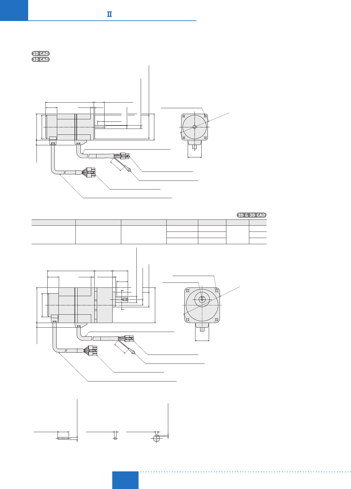
D-106
D-106 Brushless Motors/BX
Series
ORIENTAL MOTOR GENERAL CATALOG
2015/2016 Page
Features D-86 / System Configuration D-89 / Product Line D-90 / Specifications D-92 / Characteristics D-92
Dimensions D-99 / Connection and Operation D-112 / Motor and Driver Combinations D-115
Round Shaft Type
BXS230AM-A-3, BXS230CM-A-3
Motor: BXM230M-A2
Mass: 1.0 kg (2.2 lb.)
C156
60 (2.36)
11 (0.43)
ϕ54 (ϕ2.13)
110 (4.33)
Housing: 5557-10R (MOLEX)
Round Terminal: SRA-51T-4 (JST)
Housing: 5557-06R (MOLEX)
Encoder Cable ϕ8 (ϕ0.31), 400 mm (16 in.) Length
31
(1.22)
4×ϕ4.5 (ϕ0.177) Thru
ϕ
70
±
0.5
(ϕ
2.76
±0.02)
28
(0.31)
(
0.08
)
26
(1.02)
7.5 (0.30)
16 (0.63)
24±1 (0.94±0.04)
□60
ϕ8−0.015
(
ϕ0.3150−0.0006
)
00
0
0
ϕ54−0.030
(
ϕ2.1260−0.0012
)
(□2.36)
Motor Cable ϕ9 (ϕ0.35), 400 mm (16 in.) Length
200
(8)
Electromagnetic Brake Type 60 W (1/12 HP)
Motor/Parallel Shaft Gearhead
Product Name Motor Product Name Gearhead Product Name Gear Ratio L Mass kg (lb.) 2D CAD
BXS460AM-□S-3
BXS460CM-□S-3 BXM460M-GFS GFS4G□
520 41 (1.61) 2.5
(5.5)
C154A
30100 46 (1.81) C154B
200 51 (2.01) C154C
ϕ54 (ϕ2.13)
A
A
80 (3.15)
11 (0.43)
L107.5 (4.23)4×ϕ6.5 (ϕ0.256) Thru
Motor Cable ϕ9 (ϕ0.35), 400 mm (16 in.) Length
Housing: 5557-10R (MOLEX)
Housing: 5557-06R (MOLEX)
Encoder Cable ϕ8 (ϕ0.31), 400 mm (16 in.) Length
Round Terminal: SRA-51T-4 (JST)
◇Key and Key Slot (Included)
A – A
ϕ
94
±
0.5
5−0.03
0
(
0.1969−0.0012
)
0
5 0
+0.040
(
0.1969 0
)
+0.0016
25±0.2
(0.984±0.008)
5−0.03
(
0.1969−0.0012
)
00
+0.1
3 0
(
0.118 0
)
+0.004
31
(1.22)
(ϕ3.70
±
0.02
)
26
(1.02)
8
(0.31)
7
(0.28)25
35±1
(1.38
±
0.04)
(0.98)
0
0
ϕ15−0.018
(
ϕ0.5906−0.0007
)
13±0.5 (0.51±0.02)
ϕ34 (ϕ1.34)
□80
(□3.15)
200
(8)
M5×10 (0.39) Deep
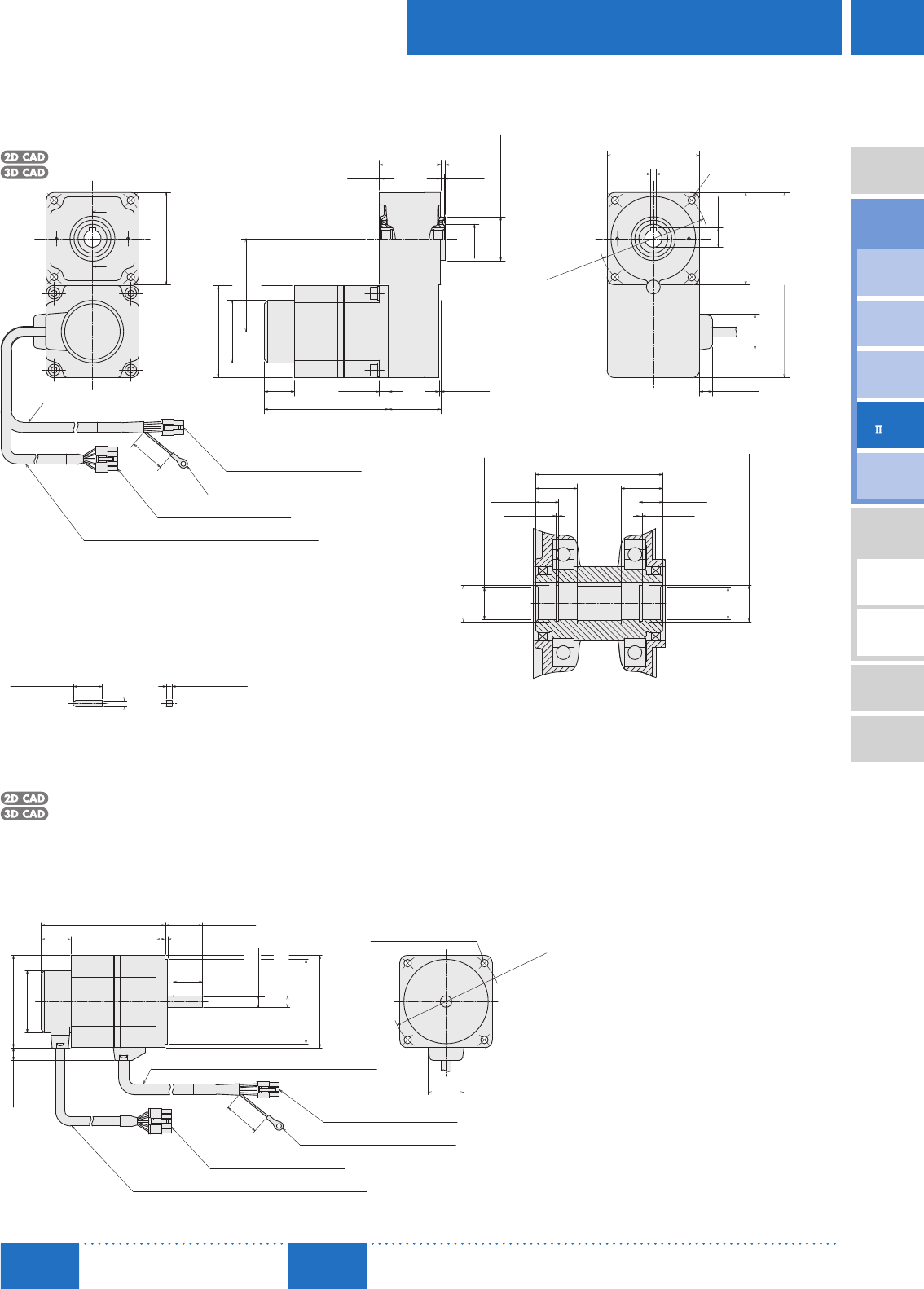
D-107
Brushless Motors/AC Speed Control Motors
D-107
Brushless
Motors
Overview,
Product
Series
AC Input
BMU
AC Input
BLE
AC Input
BLF
AC Input
BX
DC Input
BLH
DSC
BHF
AC Speed
Control
Motors
Accessories
Installation
CAD Data
Manuals www.orientalmotor.com Technical
Support TEL: (800) 468-3982
E-mail: techsupport@orientalmotor.com
Motor/Hollow Shaft Flat Gearhead
BXS460AM-□FR-3, BXS460CM-□FR-3
Motor: BXM460M-GFS
Gearhead: GFS4G□FR
Mass: 3.1 kg (6.8 lb.)
C200 53.2 (2.09)
79.5 (3.13)
80.5
(3.17)
80 (3.15)
1.5 (0.06)
107.5
A
A
26
ϕ25
Encoder Cable ϕ8 (ϕ0.31), 400 mm (16 in.) Length
Housing: 5557-10R (MOLEX)
Round Terminal: SRA-51T-4 (JST)
Housing: 5557-06R (MOLEX)
ϕ54 (ϕ2.13)
◇Key (Included)
Motor Cable ϕ9 (ϕ0.35), 400 mm (16 in.) Length
200
(8)
1 3 (0.12)
4 (0.16)
(0.04)
ϕ38−0.039
0
0
(
ϕ1.4961−0.0015
)
(ϕ0.98)
8 (0.31)
(1.02)45.2
(4.23)(
1.78)
80 (3.15)
80 (3.15)
160.5 (6.32)
4×ϕ6.5 (ϕ0.256) Thru
17.3
(0.68)
31
(1.22)
5 0
0.040
(
0.1969 0
)
0.0016
11 (0.43)
ϕ94±0.5
(
ϕ
3.70
±
0.02
)
18
(0.71)
18
(0.71)
55.2 (2.17)
A – A
0.0011
0.027
ϕ15 0
(
ϕ0.5906 0
)
ϕ15.7 0
(
ϕ0.6181 0
)
0.11 0.0043
0.0011
0.027
ϕ15 0
(
ϕ0.5906 0
)
10 (0.39)10 (0.39)
(0.05)
1.15
(0.05)
1.15
ϕ15.7 0
(
ϕ0.6181 0
)
0.11 0.0043
5−0.03
0
(
0.1969−0.0012
)
0
25±0.2
(0.984±0.008)
5−0.03
(
0.1969−0.0012
)
00
Round Shaft Type
BXS460AM-A-3, BXS460CM-A-3
Motor: BXM460M-A2
Mass: 1.5 kg (3.3 lb.)
C157
80 (3.15)
11 (0.43)
107.5 (4.23)
ϕ54 (ϕ2.13)
Encoder Cable ϕ8 (ϕ0.31), 400 mm (16 in.) Length
Housing: 5557-10R (MOLEX)
Round Terminal: SRA-51T-4 (JST)
Housing: 5557-06R (MOLEX)
200
(8)
Motor Cable ϕ9 (ϕ0.35), 400 mm (16 in.) Length
4×ϕ6.5 (ϕ0.256) Thru
ϕ
94
±
0.5
(
ϕ
3.70
±0.02)
31
(1.22)
26
(1.02)
28
(0.31) (0.08)
9.5 (0.37)
0
0
ϕ73−0.030
(
ϕ2.8740−0.0012
)
ϕ10−0.015
(
ϕ0.3937−0.0006
)
00
□80
(□3.15)
32±1
(1.26±0.04)
25
(
0.98)
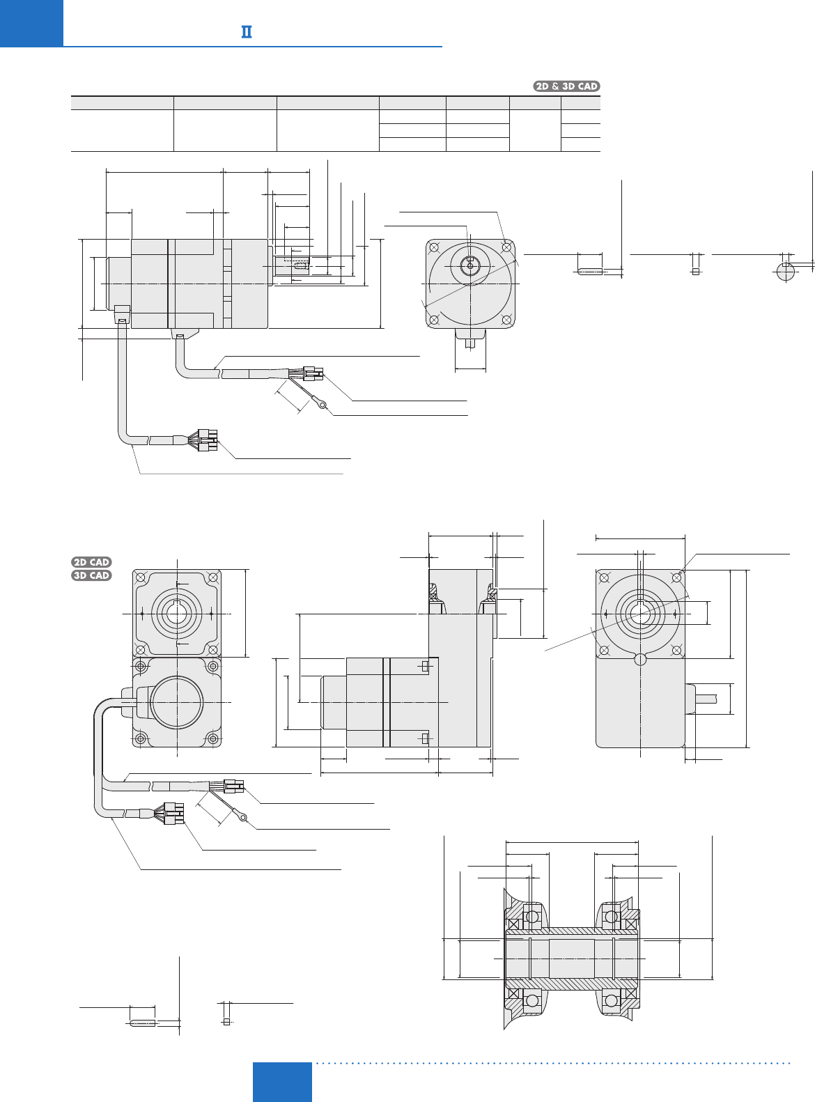
D-108
D-108 Brushless Motors/BX
Series
ORIENTAL MOTOR GENERAL CATALOG
2015/2016 Page
Features D-86 / System Configuration D-89 / Product Line D-90 / Specifications D-92 / Characteristics D-92
Dimensions D-99 / Connection and Operation D-112 / Motor and Driver Combinations D-115
Electromagnetic Brake Type 120 W (1/6 HP)
Motor/Parallel Shaft Gearhead
Product Name Motor Product Name Gearhead Product Name Gear Ratio L Mass kg (lb.) 2D CAD
BXS5120AM-□S-3
BXS5120CM-□S-3 BXM5120M-GFS GFS5G□
520 45 (1.77) 3.7
(8.1)
C155A
30100 58 (2.28) C155B
200 64 (2.52) C155C
A
A
L
5 (0.20)
42±1
34±0.5
25
1026
119 (4.69)
200
ϕ18
−
0.018
0
□90
ϕ
104
±
0.5
Housing: 5557-10R (MOLEX)
Round Terminal: SRA-51T-4 (JST)
Housing: 5557-06R (MOLEX)
ϕ20 (ϕ0.79)
ϕ40 (ϕ1.57)
18±0.5 (0.71±0.02)
90 (3.54)
11 (0.43)
ϕ54 (ϕ2.13)
(1.02)
(0.39)
(□3.54)
(1.22)
Motor Cable ϕ9 (ϕ0.35), 400 mm (16 in.) Length
Encoder Cable ϕ8 (ϕ0.31), 400 mm (16 in.) Length
M6×12 (0.47) Deep
4×ϕ8.5 (ϕ0.335) Thru
(8)
(0.98)
(1.65
±
0.04)
(
1.34
±
0.02
)
(
ϕ
4.09
±
0.02
)
(
ϕ
0.7087
−0.0007
)
0
31
Motor/Hollow Shaft Flat Gearhead
BXS5120AM-□FR-3, BXS5120CM-□FR-3
Motor: BXM5120M-GFS
Gearhead: GFS5G□FR
Mass: 4.4 kg (9.7 lb.)
C201
55.2119
10 2
A
A
ϕ54
26
200
Housing: 5557-10R (MOLEX)
Round Terminal: SRA-51T-4 (JST)
Housing: 5557-06R (MOLEX)
89 (3.50)
Motor Cable ϕ9 (ϕ0.35), 400 mm (16 in.) Length
Encoder Cable ϕ8 (ϕ0.31), 400 mm (16 in.) Length
67.2 (2.65)
13 (0.51)13 (0.51)
(0.05)(
0.05)
1.15 1.15
22 (0.87)22 (0.87)
ϕ21 0
+0.21
ϕ21 0
+0.21
ϕ20 0
+0.033
ϕ20 0
+0.033
A – A
(
ϕ0.7874 0
)
+0.0013
(
ϕ0.7874 0
)
+0.0013
(
ϕ0.8268 0
)
+0.0083
(
ϕ0.8268 0
)
+0.0083
(8)
90
22.8
31
11
90
180
ϕ
104±
0.5
4×ϕ8.5 (ϕ0.335) Thru
6 0
+0.040
(
0.2362 0
)
+0.0016
(ϕ4.09
±
0.02)
(3.54)
(0.43)
(1.22)
(7.09)
(3.54)
(
0.90
)
90 (3.54)
90 (3.54)
(1.02)
(4.69)
(0.39)
(2.17)
(0.08)
65.2 4
31
ϕ30
ϕ50−0.039
0
(
ϕ1.9685−0.0015
)
0
(2.57)
(0.04)
(0.16)
(0.12)
(ϕ1.181)
(ϕ2.13)
25±0.2
6−0.03
0
6−0.03
0 6 0
+0.040
3.5 0
+0.1
A – A
◇Key and Key Slot (Included)
(
ϕ0.138 0
)
+0.004
(
0.2362 0
)
+0.0016
(
0.2362−0.0012
)
0
(
0.2362−0.0012
)
0
(0.984±0.008)
25±0.2
6−0.03
0
6−0.03
0
◇Key (Included)
(
0.2362−0.0012
)
0
(
0.2362−0.0012
)
0
(0.984
±
0.008)
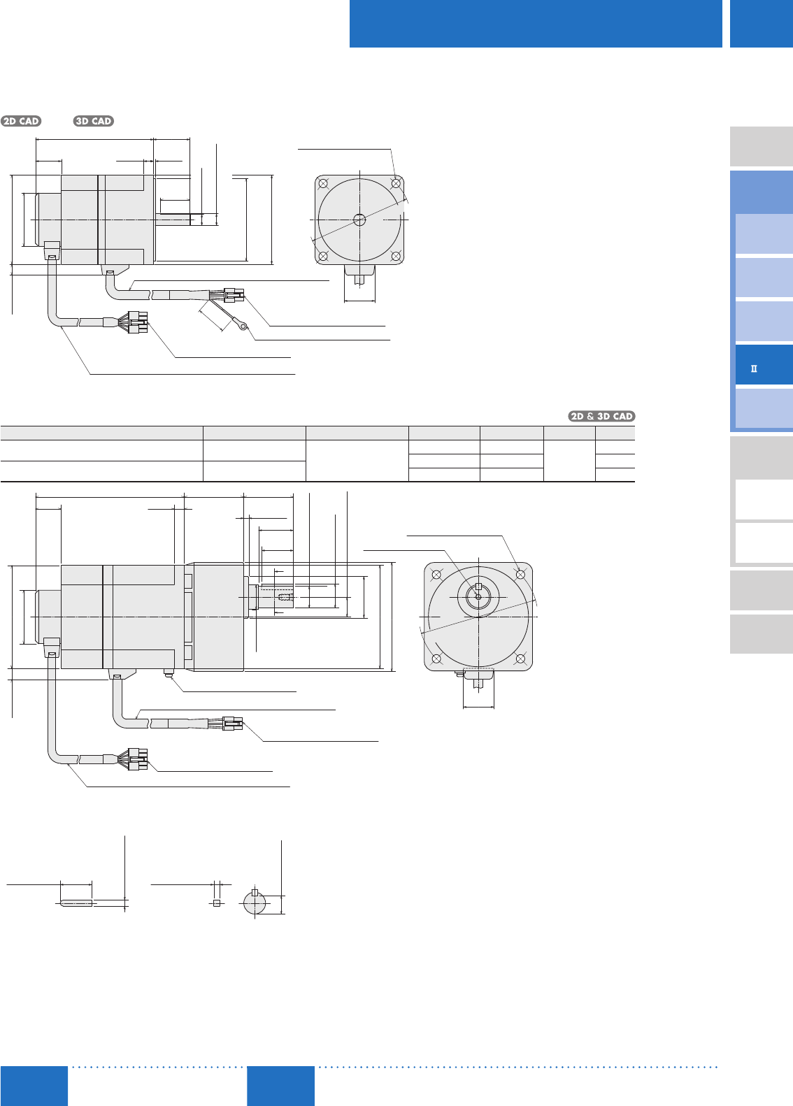
D-109
Brushless Motors/AC Speed Control Motors
D-109
Brushless
Motors
Overview,
Product
Series
AC Input
BMU
AC Input
BLE
AC Input
BLF
AC Input
BX
DC Input
BLH
DSC
BHF
AC Speed
Control
Motors
Accessories
Installation
CAD Data
Manuals www.orientalmotor.com Technical
Support TEL: (800) 468-3982
E-mail: techsupport@orientalmotor.com
Round Shaft Type
BXS5120AM-A-3, BXS5120CM-A-3
Motor: BXM5120M-A2
Mass: 2.2 kg (4.8 lb.)
C158
1026
119 (4.69)
200
Housing: 5557-10R (MOLEX)
Round Terminal: SRA-51T-4 (JST)
Housing: 5557-06R (MOLEX)
Motor Cable ϕ9 (ϕ0.35), 400 mm (16 in.) Length
Encoder Cable ϕ8 (ϕ0.31), 400 mm (16 in.) Length
90 (3.54)
11 (0.43)
ϕ54 (ϕ2.13)
(0.39)
(1.02)
(8)
30
11.5 (0.45)
2
37±1
ϕ12
−
0.018
0
ϕ83
−
0.035
0
□90
(1.18)
(0.08)
(
1.46
±0.04)
(□3.54)
(
ϕ3.2677−0.0014
)
0
(
ϕ0.4724−0.0007
)
0
ϕ
104
±
0.5
31
(1.22)
4×ϕ8.5 (ϕ0.335) Thru
(
ϕ
4.09
±
0.02
)
Electromagnetic Brake Type 200 W (1/4 HP), 400 W (1/2 HP)
Motor/Parallel Shaft Gearhead
Product Name Motor Product Name Gearhead Product Name Gear Ratio L Mass kg (lb.) 2D CAD
BXS6200AM-□S-3, BXS6200CM-□S-3 BXM6200M-GFS
GFS6G□
520 60 (2.36) 6.5
(14)
C202A
30, 50 72 (2.83) C202B
BXS6400CM-□S-3 BXM6400M-GFS 100, 200 86 (3.39) C202C
1026
150 (5.91)L
Housing: 5557-10R (MOLEX)
Housing: 5557-06R (MOLEX)
Protective Earth Terminal M4
A – A
32
±0.2
18.5 0
−
0.1
◇Key and Key Slot (Included)
104 (4.09)
11 (0.43)
ϕ54 (ϕ2.13)
(0.39)
(1.02)
M6×12 (0.47) Deep
ϕ120±0.5
(1.22)
(ϕ4.72
±0.02
)
4×ϕ8.5 (ϕ0.335) Thru
6−0.03
0
(
0.2362−0.0012
)
0
(
0.728−0.004
)
0
6−0.03
0
(
0.2362−0.0012
)
0
(1.260±0.008)
A
A
32
35±0.5
50±1
24.5 (0.96)
5 (0.20)
20±0.5
□104 (□4.09)
□110 (□4.33)
ϕ22
−
0.021
0
(1.26)
(
1.38
±
0.02)
(1.97±0.04)
(
ϕ0.8661−0.0008
)
0
ϕ42 (ϕ
1.65
)
ϕ25
(0.79±0.02)
(ϕ0.98)
Motor Cable ϕ9 (ϕ0.35), 400 mm (16 in.) Length
Encoder Cable ϕ8 (ϕ0.31), 400 mm (16 in.) Length
31
At the time of shipment, a key is inserted on the gearhead’s shaft.
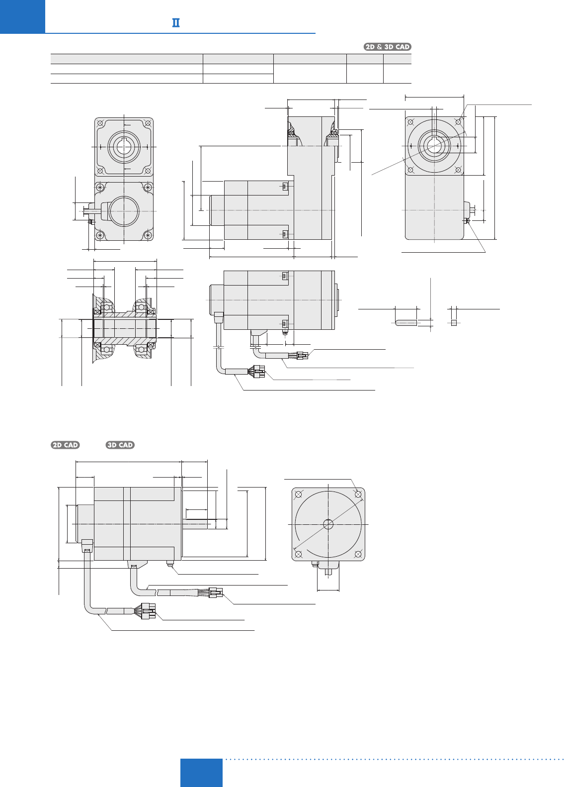
D-110
D-110 Brushless Motors/BX
Series
ORIENTAL MOTOR GENERAL CATALOG
2015/2016 Page
Features D-86 / System Configuration D-89 / Product Line D-90 / Specifications D-92 / Characteristics D-92
Dimensions D-99 / Connection and Operation D-112 / Motor and Driver Combinations D-115
Motor/Hollow Shaft Flat Gearhead
Product Name Motor Product Name Gearhead Product Name Mass kg (lb.) 2D CAD
BXS6200AM-□FR-3, BXS6200CM-□FR-3 BXM6200M-GFS GFS6G□FR 8.3
(18.3) C258
BXS6400CM-□FR-3 BXM6400M-GFS
Housing: 5557-06R(MOLEX)
Motor Cable
ϕ
9 (
ϕ0.35
), 400 mm (
16
in.) Length
Housing:
5557-10R(MOLEX)
Encoder Cable
ϕ
8 (
ϕ0.31
), 400 mm (
16
in.) Length
Key (Included)
4×ϕ8.5 (ϕ0.335) Thru
Protective Earth Terminal M4
A
A
150 (5.91)
15.528.5
ϕ120±0.5
7 0
−0.09
8 0
−0.036
30±0.2
(1.181±0.008)
(
0.3150−0.0014
)
0
31 (1.22)
11 (0.43)
ϕ54 (ϕ2.13)
114 (4.49)
104 (4.09)
10 (0.39)
26 (1.02)
67 (2.64)5 (0.20)
5 (0.20)
7 (0.276)
83.5 (3.29)
1 (0.04)
ϕ40 (ϕ1.57)
(ϕ4.72
±0.02
)
18.5 (0.73)104 (4.09)
218 (8.58)
28.3 (1.11)
104 (4.09)
(1.12)(0.61)
(
0.2756−0.0035
)
0
8+0.040
0
(
0.3150 0
)
+0.0016
ϕ58 0
−0.046
(
ϕ2.2835−0.0018
)
0
89.5 (3.52)
1.35
(0.05)
15 (0.59)
30 (1.18)
1.35
(0.05)
15 (0.59)
30 (1.18)
ϕ26.2
+
0.21
(
ϕ1.0315+0.0083
)
0
0
ϕ25
+
0.033
(
ϕ0.9843+0.0013
)
0
0
ϕ25
+
0.033
(
ϕ0.9843+0.0013
)
0
0
ϕ26.2
+
0.21
(
ϕ1.0315+0.0083
)
0
0
A−A
Round Shaft Type
BXS6200AM-A-3, BXS6200CM-A-3, BXS6400CM-A-3
Motor: BXM6200M-A, BXM6400M-A
Mass: 3.5 kg (7.7 lb.)
C184
2
37±1
1026
150 (5.91)
Housing: 5557-10R (MOLEX)
Housing: 5557-06R (MOLEX)
Protective Earth Terminal M4
Motor Cable ϕ9 (ϕ0.35), 400 mm (16 in.) Length
Encoder Cable ϕ8 (ϕ0.31), 400 mm (16 in.) Length
104 (4.09)
11 (0.43)
ϕ54 (ϕ2.13)
(0.39)(0.08)
(1.02)
(
1.46
±0.04)
13 (0.51)
(□4.09)
30
□104
ϕ14
−
0.018
0
ϕ94
−
0.035
0
(1.18)
(
ϕ0.5512−0.0007
)
0
(
ϕ3.7008−0.0014
)
0
ϕ120
±
0.5
(1.22)
(
ϕ
4.72
±
0.02
)
4×ϕ8.5 (ϕ0.335) Thru
31
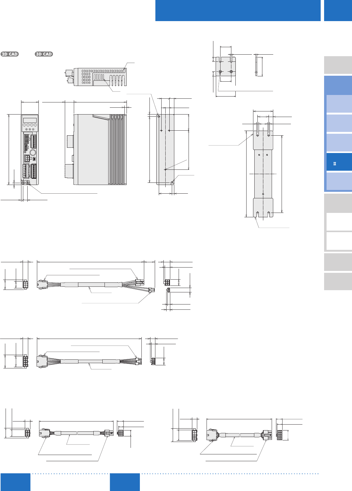
D - 111
Brushless Motors/AC Speed Control Motors
D-111
Brushless
Motors
Overview,
Product
Series
AC Input
BMU
AC Input
BLE
AC Input
BLF
AC Input
BX
DC Input
BLH
DSC
BHF
AC Speed
Control
Motors
Accessories
Installation
CAD Data
Manuals www.orientalmotor.com Technical
Support TEL: (800) 468-3982
E-mail: techsupport@orientalmotor.com
Driver (Common to all types)
BXSD30-A, BXSD30-C, BXSD60-A, BXSD60-C, BXSD120-A, BXSD120-C,
BXSD200-A, BXSD200-C, BXSD400-C
Mass: 0.8 kg (1.76 lb.)
C259
23 max.
(0.91 max.)
120 (4.72)
5
(0.20)
R2.25
(R0.089)
5
(0.20)
30
(1.18)
150 (5.91)5 (0.20)
40
(1.57)
4.5
(0.18)
160 (6.30)
9.5 (0.37)
4.8 (0.19)
36.5
(1.44)
9 (0.35)
18
(0.71)
11 (0.43)
89
(3.50)
3
×
M3
Slits
Slits
Protective Earth Terminal 2×M4
ϕ4.5 (ϕ0.177)
Thru
Connection Cable (Included)
For Motor
11.6
(0.46)
22.2 (0.87)
15.8 (0.62)
14.5 (0.57)
3000 (9.8 ft.)
11.6 (0.46)
Housing: 5559-06P (MOLEX)
Housing: 5557-06R (MOLEX)
13.8
(0.54)
Motor Side
Driver Side
ϕ8 (ϕ0.31)
For Encoder
Driver Side
Encoder Side
11.6 (0.46)
14.5 (0.57)
22.2
(0.87)
ϕ8 (ϕ0.31)
Housing: 5559-10P (MOLEX)
Housing: 5557-10R (MOLEX)
11.6
(0.46)
30.6 (1.20)
24.2 (0.95)
3000 (9.8 ft.)
Driver Mounting Bracket (A set of 2 pieces)
45
(1.77)
25
25
2× 3.5 ( 0.138) Countersink
10
(0.39)
10
(0.39)
4.5 (0.18)3 (0.12)
43
(1.69)
(0.98)
(0.98)
When the driver mounting brackets are attached
4.5
(0.18)
4.5 (0.18)
10 (0.39)
25
(0.98)
45 (1.77)
196 (7.72)
176 (6.93)
Mounting Bracket
Mounting Bracket
Conversion Cables (Included)
2 cables:,one for the motor and one for the encoder, come as a set.
For Motor
11.6 (0.46)
22.2
(0.87)
15.8
(0.62)
9 (0.35)
240 (9.4)24
(0.9)
14.5 (0.57)
11.6 (0.46)
13.8
(0.54)
9.9
(0.39)
5.3 (0.21)
7.9 (0.31)
Housing: 5557-06R-210 (MOLEX)
Housing: 43645-0300 (MOLEX)
Housing: 5559-06P (MOLEX)
Driver Side
Motor Side
For Encoder
ϕ8 (ϕ0.31)
11.6 (0.46)
30.6
(1.20)
24.2
(0.95)
240 (9.4)
8.3 (0.33)
10.9 (0.43)
15.8
(0.62)
Housing: 5559-10P (MOLEX)
Housing: 43025-1000 (MOLEX)
Driver SideMotor Side
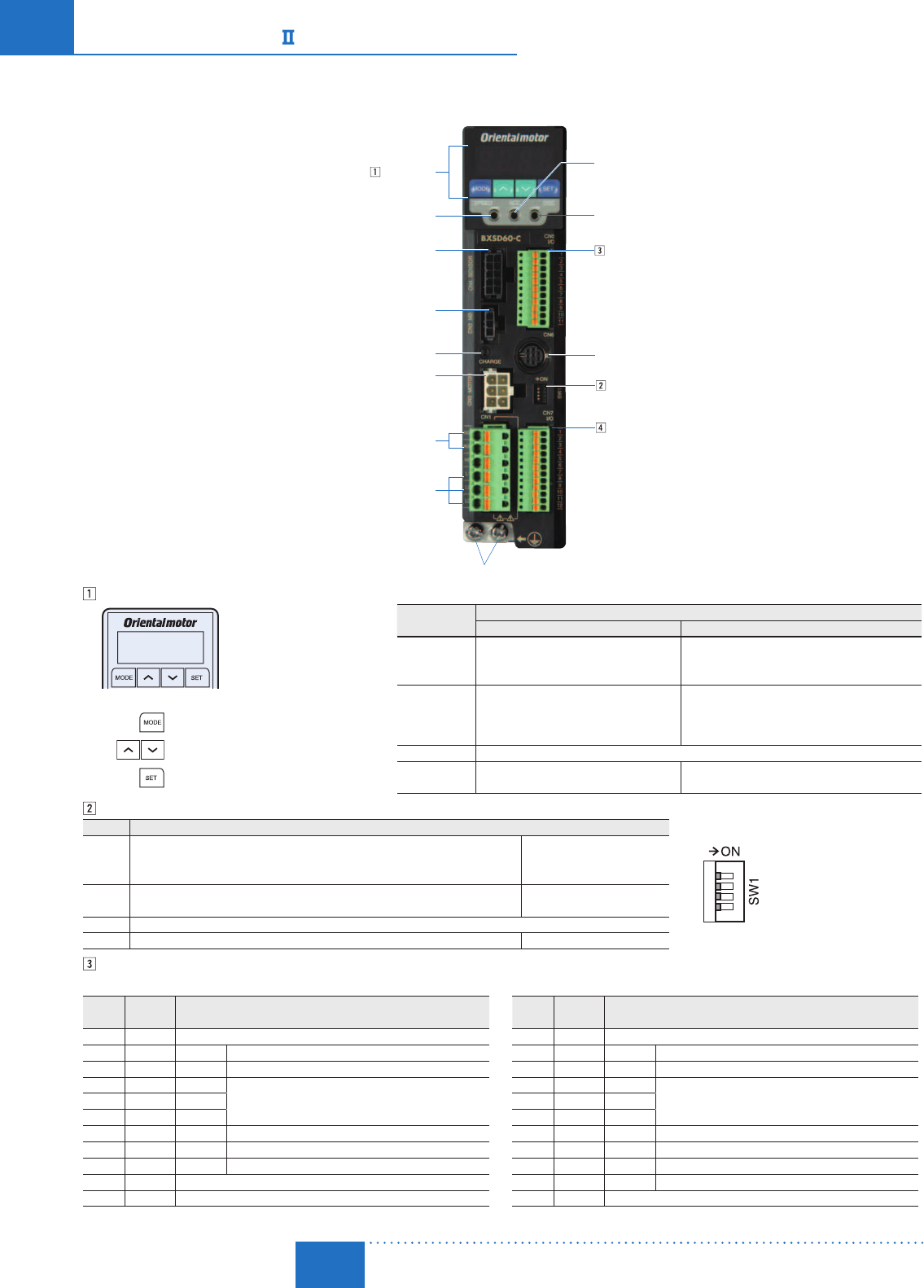
D-112
D-112 Brushless Motors/BX
Series
ORIENTAL MOTOR GENERAL CATALOG
2015/2016 Page
Features D-86 / System Configuration D-89 / Product Line D-90 / Specifications D-92 / Characteristics D-92
Dimensions D-99 / Connection and Operation D-112 / Motor and Driver Combinations D-115
■Connection and Operation
Names and Functions of Driver Parts
Control Panel
Internal Speed Potentiometer (SPEED)
Encoder Connector (CN4)
Electromagnetic Brake Connector (CN3)
Regeneration Unit Connection Terminals (CN1)
CHARGE LED (Red)
Motor Connector (CN2)
Main Power Input Terminals (CN1)
Acceleration Time Potentiometer (ACC)
Control Module Connector (CN6)
Input Signal Connector (CN5)
Deceleration Time Potentiometer (DEC)
I/O Signals Connector (CN7)
Function Switch (SW1)
Protective Earth Terminals
Control Panel
Key: Changes the operating mode
Key: Changes the setting value
Key: Sets the data
Operating Mode Details
Speed Control Position Control
Monitoring Speed, Load Factor, Operation Number, Alarm
Code, Warning Code, I/O Monitor, Control Mode
Speed, Position, Load Factor, Operation Number,
Selection Number, Alarm Code, Warning Code, I/O
Monitor, Control Mode
Data
Data No. 015 (16 points)
Operating Speed, Torque Limit, Acceleration
Time, Deceleration Time, Data Clear
Data No. 015 (16 points)
Operating Mode, Position, Operating Speed, Operation
Function, Sequential Positioning, Torque Limiting,
Acceleration Time, Deceleration Time, Data Clear
Parameters Sets various parameters
Tests I/O test, JOG Operation, Data No. Selection
Operation, Teaching
I/O test, JOG Operation, Data No. Selection Operation,
Return-to-Home Operation, Position Preset, Teaching
Function Switch (SW1)
No. Function
1
3
2
4
1
Switching between speed control mode and position control mode
ON: Position control mode
OFF: Speed control mode
Factory setting: OFF
2Setting the BX compatibility mode
When ON, the BX Series' I/O signal and contents can be combined. Factory setting: OFF
3 Not used
4 Selecting the power supply for input signals (built-in or external) Factory setting: OFF (external)
Input Signals Connector (CN5, 11 pins)
For Speed Control Mode
Pin No. Signal
Name Function
1 IN-COM0 Input signal common
2 IN0 FWD Rotation in FWD direction/deceleration stop
3 IN1 RVS Rotation in RVS direction/deceleration stop
4 IN2 M0
Operating data No. selection5 IN3 M1
6 IN4 M2
7 IN5 FREE Motor excitation cancellation, electromagnetic brake release
8 IN6 STOP Instantaneous stop when input during motor operation
9 IN7 ALM-RST Alarm cancellation
10 IN8 Not used (functions can be extended)
11 IN-COM1 Input signal common (0 V)
For Position Control Mode
Pin No. Signal
Name Function
1 IN-COM0 Input signal common
2 IN0 HOME Return-to-home operation start
3 IN1 START Positioning operation start
4 IN2 M0
Operating data No. selection5 IN3 M1
6 IN4 M2
7 IN5 FREE Motor excitation cancellation, electromagnetic brake release
8 IN6 STOP Instantaneous stop when input during motor operation
9 IN7 ALM-RST Alarm cancellation
10 IN8 HOMES Mechanical home sensor
11 IN-COM1 Input signal common (0 V)
The functions allocated to IN0IN8 are the initial values. The contents can be changed with the parameters.

D-113
Brushless Motors/AC Speed Control Motors
D-113
Brushless
Motors
Overview,
Product
Series
AC Input
BMU
AC Input
BLE
AC Input
BLF
AC Input
BX
DC Input
BLH
DSC
BHF
AC Speed
Control
Motors
Accessories
Installation
CAD Data
Manuals www.orientalmotor.com Technical
Support TEL: (800) 468-3982
E-mail: techsupport@orientalmotor.com
I/O Signals Connector (CN7, 12 pins)
For Speed Control Mode
Pin No. Signal
Name Function
1VH
External analog setting input
Connect when controlling with PAVR-20KZ or external DC
voltage.
2VM
3VL
4 OUT0+ALM Output when an alarm is generated
5 OUT0−
6 OUT1+MOVE Output when the motor is operating
7 OUT1−
8 OUT2+WNG Output when a warning is generated
9 OUT2−
10 ASG A-phase output
11 BSG B-phase output
12 OUT-COM Common for ASG/BSG
For Position Control Mode
Pin No. Signal
Name Function
1VH
External analog setting input
Connect when controlling with PAVR-20KZ or external DC
voltage.
2VM
3VL
4 OUT0+ALM Output when an alarm is generated
5 OUT0−
6 OUT1+READY Output when operation preparations are completed
7 OUT1−
8 OUT2+HOME-P Output during home detection
9 OUT2−
10 ASG A-phase output
11 BSG B-phase output
12 OUT-COM Common for ASG/BSG
The functions allocated to OUT0OUT2 are the initial values. The contents can be changed with the parameters.
Connection Diagram
Connection Example
PE
PE
Connection Cable
Connection Cable
Conversion Cables (Included)
Conversion Cables (Included)
Motor
Cable
Encoder
Cable
Regeneration Unit
Connect to CN1
Main Power Supply
Connect to CN1
Input Signal
Connect to CN5
Output Signal
Connect to CN7
Analog External
Potentiometer
Connect to CN7
Encoder Connector
Connect to CN4
Electromagnetic Brake Connector
Connect to CN3
Motor Power Connector
Connect to CN2
Note
Always use the included conversion cable when connecting the motor.
Always connect the electromagnetic brake connector to CN3 regardless of whether or not there is an electromagnetic brake.
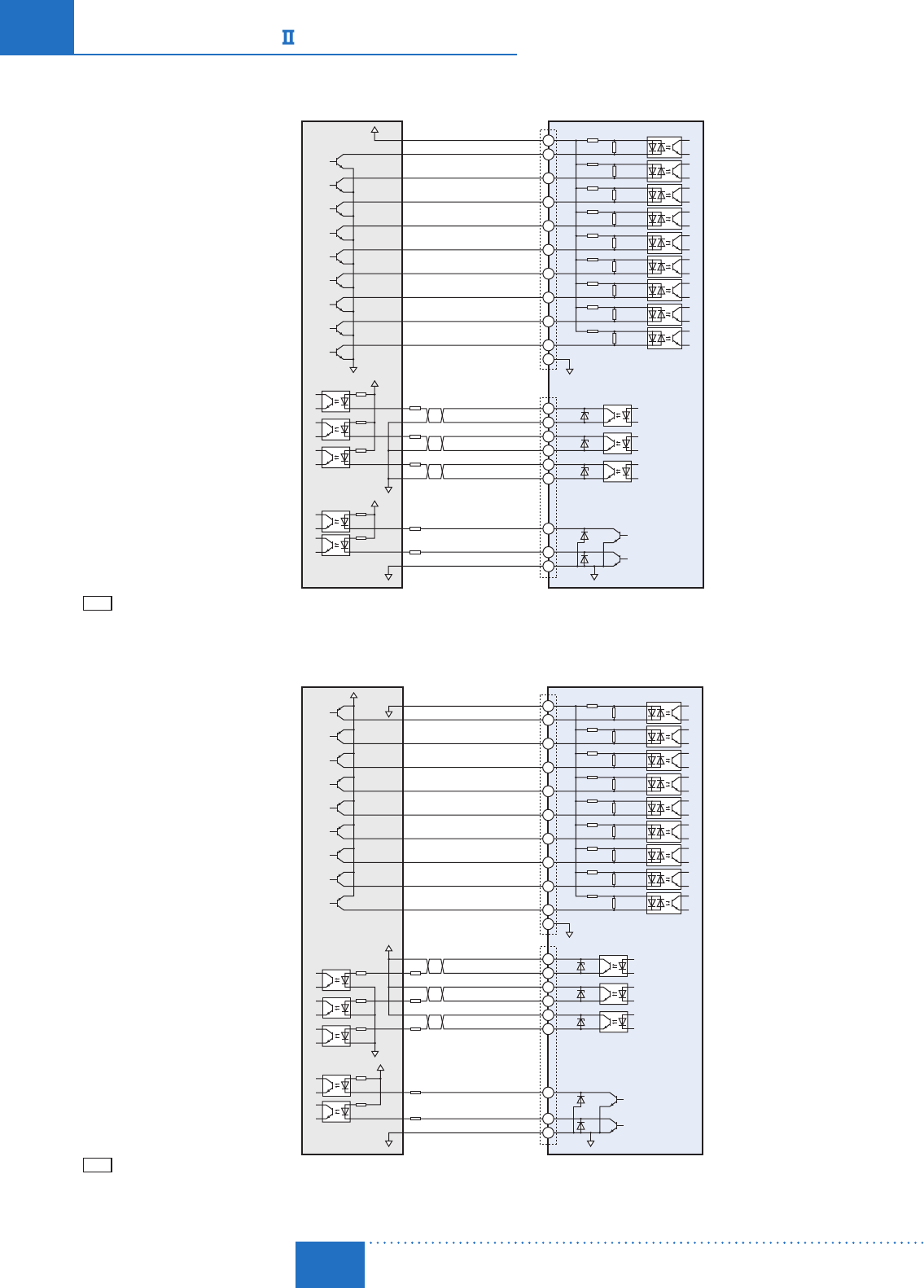
D-114
D-114 Brushless Motors/BX
Series
ORIENTAL MOTOR GENERAL CATALOG
2015/2016 Page
Features D-86 / System Configuration D-89 / Product Line D-90 / Specifications D-92 / Characteristics D-92
Dimensions D-99 / Connection and Operation D-112 / Motor and Driver Combinations D-115
Connection to Programmable Controller
Sink Logic
24 VDC CN5
CN7
30 VDC max.
100 mA max.→
IN-COM0
IN0
IN1
IN2
IN3
IN4
IN5
IN6
IN7
IN8
IN-COM1
OUT0+
OUT0−
OUT1+
OUT1−
OUT2+
OUT2−
ASG
BSG
OUT-COM
100 mA max.→
0 V
2
1
3
4
5
6
7
9
6.6 k820
6.6 k820
6.6 k820
6.6 k820
6.6 k820
6.6 k820
6.6 k820
6.6 k820
6.6 k820
8
10
4
R1
R1
100 mA max.→
R1
6
5
7
Programmable Controller Driver
8
9
30 VDC max.
20 mA max.→
20 mA max.→
0 V 0 V
10
R2
R2 11
12
11
0 V 0 V
Note
Use output signals 30 VDC or less.
Always connect a current limiting resistor R1 to OUT0OUT2 and keep the current at 100 mA or less.
Always connect a current limiting resistor R2 to ASG and BSG and keep the current at 20 mA or less.
Source Logic
24 VDC CN5
CN7
30 VDC max. 100 mA max.→
100 mA max.→
0 V
2
1
3
4
5
6
7
96.6 kΩ
6.6 kΩ
6.6 kΩ
6.6 kΩ
6.6 kΩ
6.6 kΩ
6.6 kΩ820 Ω
820 Ω
820 Ω
820 Ω
820 Ω
820 Ω
86.6 kΩ820 Ω
820 Ω
10 6.6 kΩ820 Ω
4
R1
R1
100 mA max.→
R1
6
5
7
Programmable Controller Driver
8
9
30 VDC max.
20 mA max.→
20 mA max.→
0 V 0 V
10
R2
R2 11
12
11
0 V
0 V
IN-COM0
IN0
IN1
IN2
IN3
IN4
IN5
IN6
IN7
IN8
IN-COM1
OUT0+
OUT0−
OUT1+
OUT1−
OUT2+
OUT2−
ASG
BSG
OUT-COM
Note
Use output signals 30 VDC or less.
Always connect a current limiting resistor R1 to OUT0OUT2 and keep the current at 100 mA or less.
Always connect a current limiting resistor R2 to ASG and BSG and keep the current at 20 mA or less. ASG and BSG are not compatible with source logic.
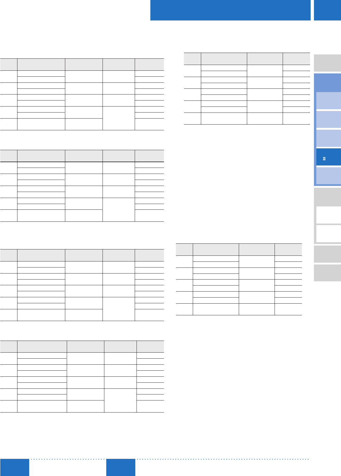
D-115
Brushless Motors/AC Speed Control Motors
D-115
Brushless
Motors
Overview,
Product
Series
AC Input
BMU
AC Input
BLE
AC Input
BLF
AC Input
BX
DC Input
BLH
DSC
BHF
AC Speed
Control
Motors
Accessories
Installation
CAD Data
Manuals www.orientalmotor.com Technical
Support TEL: (800) 468-3982
E-mail: techsupport@orientalmotor.com
■ Motor and Driver Combinations
Standard Type
Combination Type with a Parallel Shaft Gearhead
The combination type comes with the motor and parallel shaft gearhead pre-assembled.
Output
Power Product Name Motor
Product Name
Gearhead
Product Name
Driver
Product Name
30 W
(1/25 HP)
BXS230A-□S-3 BXM230-GFS GFS2G□BXSD30-A
BXS230C-□S-3 BXSD30-C
60 W
(1/12 HP)
BXS460A-□S-3 BXM460-GFS GFS4G□BXSD60-A
BXS460C-□S-3 BXSD60-C
120 W
(1/6 HP)
BXS5120A-□S-3 BXM5120-GFS GFS5G□BXSD120-A
BXS5120C-□S-3 BXSD120-C
200 W
(1/4 HP)
BXS6200A-□S-3 BXM6200-GFS
GFS6G□
BXSD200-A
BXS6200C-□S-3 BXSD200-C
400 W
(1/2 HP) BXS6400C-□S-3 BXM6400-GFS BXSD400-C
Combination Type with a Hollow Shaft Flat Gearhead
The combination type comes with the motor and hollow shaft flat gearhead pre-assembled.
Output
Power Product Name Motor
Product Name
Gearhead
Product Name
Driver
Product Name
30 W
(1/25 HP)
BXS230A-□FR-3 BXM230-GFS GFS2G□FR BXSD30-A
BXS230C-□FR-3 BXSD30-C
60 W
(1/12 HP)
BXS460A-□FR-3 BXM460-GFS GFS4G□FR BXSD60-A
BXS460C-□FR-3 BXSD60-C
120 W
(1/6 HP)
BXS5120A-□FR-3 BXM5120-GFS GFS5G□FR BXSD120-A
BXS5120C-□FR-3 BXSD120-C
200 W
(1/4 HP)
BXS6200A-□FR-3 BXM6200-GFS
GFS6G□FR
BXSD200-A
BXS6200C-□FR-3 BXSD200-C
400 W
(1/2 HP) BXS6400C-□FR-3 BXM6400-GFS BXSD400-C
Round Shaft Type
Output
Power Product Name Motor
Product Name
Driver
Product Name
30 W
(1/25 HP)
BXS230A-A-3 BXM230-A2 BXSD30-A
BXS230C-A-3 BXSD30-C
60 W
(1/12 HP)
BXS460A-A-3 BXM460-A2 BXSD60-A
BXS460C-A-3 BXSD60-C
120 W
(1/6 HP)
BXS5120A-A-3 BXM5120-A2 BXSD120-A
BXS5120C-A-3 BXSD120-C
200 W
(1/4 HP)
BXS6200A-A-3 BXM6200-A BXSD200-A
BXS6200C-A-3 BXSD200-C
400 W
(1/2 HP) BXS6400C-A-3 BXM6400-A BXSD400-C
A number indicating the gear ratio is entered where the box □ is located within the product name.
Electromagnetic Brake Type
Combination Type with a Parallel Shaft Gearhead
The combination type comes with the motor and parallel shaft gearhead pre-assembled.
Output
Power Product Name Motor
Product Name
Gearhead
Product Name
Driver
Product Name
30 W
(1/25 HP)
BXS230AM-□S-3 BXM230M-GFS GFS2G□BXSD30-A
BXS230CM-□S-3 BXSD30-C
60 W
(1/12 HP)
BXS460AM-□S-3 BXM460M-GFS GFS4G□BXSD60-A
BXS460CM-□S-3 BXSD60-C
120 W
(1/6 HP)
BXS5120AM-□S-3 BXM5120M-GFS GFS5G□BXSD120-A
BXS5120CM-□S-3 BXSD120-C
200 W
(1/4 HP)
BXS6200AM-□S-3 BXM6200M-GFS
GFS6G□
BXSD200-A
BXS6200CM-□S-3 BXSD200-C
400 W
(1/2 HP) BXS6400CM-□S-3 BXM6400M-GFS BXSD400-C
Combination Type with a Hollow Shaft Flat Gearhead
The combination type comes with the motor and hollow shaft flat gearhead pre-assembled.
Output
Power Product Name Motor
Product Name
Gearhead
Product Name
Driver
Product Name
30 W
(1/25 HP)
BXS230AM-□FR-3 BXM230M-GFS GFS2G□FR BXSD30-A
BXS230CM-□FR-3 BXSD30-C
60 W
(1/12 HP)
BXS460AM-□FR-3 BXM460M-GFS GFS4G□FR BXSD60-A
BXS460CM-□FR-3 BXSD60-C
120 W
(1/6 HP)
BXS5120AM-□FR-3 BXM5120M-GFS GFS5G□FR BXSD120-A
BXS5120CM-□FR-3 BXSD120-C
200 W
(1/4 HP)
BXS6200AM-□FR-3 BXM6200M-GFS
GFS6G□FR
BXSD200-A
BXS6200CM-□FR-3 BXSD200-C
400 W
(1/2 HP) BXS6400CM-□FR-3 BXM6400M-GFS BXSD400-C
Round Shaft Type
Output
Power Product Name Motor
Product Name
Driver
Product Name
30 W
(1/25 HP)
BXS230AM-A-3 BXM230M-A2 BXSD30-A
BXS230CM-A-3 BXSD30-C
60 W
(1/12 HP)
BXS460AM-A-3 BXM460M-A2 BXSD60-A
BXS460CM-A-3 BXSD60-C
120 W
(1/6 HP)
BXS5120AM-A-3 BXM5120M-A2 BXSD120-A
BXS5120CM-A-3 BXSD120-C
200 W
(1/4 HP)
BXS6200AM-A-3 BXM6200M-A BXSD200-A
BXS6200CM-A-3 BXSD200-C
400 W
(1/2 HP) BXS6400CM-A-3 BXM6400M-A BXSD400-C

D-116
D-116 Brushless Motors/BX
Series
ORIENTAL MOTOR GENERAL CATALOG
2015/2016
