Flow Shimpo Gear Boxes 1505485896 User Manual
Shimpo Gear Boxes-1505485896 SHIMPO_GEAR_BOXES-1505485896 SHIMPO_GEAR_BOXES-1505485896 SHIMPO GEAR BOXES Power Transmission s production assets-flotronics
2017-09-15
User Manual: Flow Shimpo Gear Boxes-1505485896
Open the PDF directly: View PDF ![]() .
.
Page Count: 444 [warning: Documents this large are best viewed by clicking the View PDF Link!]

High Precision Gear Technology
Improving the Speed of Industry

Letter from the President
The NIDECSHIMPO Corporation was originally founded in Kyoto Japan
in . Since our inception, we have made every possible e ort to im-
prove our manufacturing skill and capabilities, including the advance-
ment of power transmission products to support new technologies and
markets. NIDECSHIMPO initially established an industry-wide leader-
ship position in the area of mechanical variable speed drives. We are very
proud of our storied past with mechanical drive technology, through
which NIDECSHIMPO helped contribute to the growth of the emerging
industries that are now the cornerstone of our world economy today.
Over time, within the eld of power transmission engineering,
NIDECSHIMPO has maintained the highest level of skill and production
quality throughout the industry. We have earned a reputation as a long
term dependable partner to our customers, and this solid reputation is
rmly supported by the many industrial awards we hold, such as the
Japanese Machinery Society Award, and Deming Award, among others.
Today, the growing global market for motion control has focused a sig-
ni cant share of our time and energy towards providing higher precision
solutions for our customers. This e ort has led to the development of our
ABLE product line, a complete o ering of high-precision planetary speed
reducers speci c to servo-motor applications. This catalog provides in-
depth technical details and speci cations for the full ABLE product line.
NIDECSHIMPO promises to continue to provide high precision power
transmission products at unmatched value, which solve the new require-
ments of our customer base and allow them to be competitive in an in-
creasingly tough global market. Within our company, we have coined this
promise as “Enduring Process of SHIMPO” - a pledge by our employees to
approach all of their day-to-day work activities with full e ort, full dedi-
cation, and full energy to support the evolving needs of our customers.
Your continued support and loyal patronage to our company is highly
appreciated. Thank you for your time.
Best Regards,
President
T. Nishimoto
Please take 30 seconds
to register your catalog.
Every 500th Registrant
will receive an award
from SHIMPO.

Table of contents
VRL-Series ................................................
Planetary Inline Con guration
General purpose
(Food/washdown options, refer to page 36-37)
VRSF-Series ...............................................
Planetary Inline Con guration
Economy class
(NEMA output dimensions, refer to page 30-31)
VRB-Series ...............................................
Planetary Inline Con guration
General purpose, simple mount
VRS-Series ..............................................
Planetary Inline Con guration
Highest radial, axial load capacity
NEV-Series .............................................
Right-angle Con guration
Economy class
EVL-Series .............................................
Planetary Right-angle Con guration
General purpose
EVB-Series .............................................
Planetary Right-angle Con guration
General purpose, simple mount
EVS-Series .............................................
Planetary Right-angle Con guration
Highest radial, axial load capacity
STH-Series ..............................................
Hollow Output Rotary Actuator
Great moment load, general duty
STR-Series .............................................
Hollow Output Rotary Actuator
Highest moment load, “zero” backlash
ER-Series ...............................................
Inline Con guration
Extreme shock load situations
Technical Information .............................. -
Commercial Information ..........................-
Company Overview ......................................
VRT-Series ..............................................
Planetary Inline Con guration
Compact, ISO ange mount
VRSFVRT VRBEVL VRLNEV VRSEVBSTH EVSER STR

NIDEC Corporation
With annual sales exceeding Billion for the scal year , the NIDEC Corporation has become the world’s dominant provider of
small precision, mid-size motors and related drive technologies. Founded in by current Chairman of the Board and CEO, Shigenobu
Nagamori, the NIDEC Corporation has built a portfolio of motor variety that is far reaching and impacts all of us during our daily routine.
Regardless if its hard disk drive motors, fan motors for appliances, or automotive related, NIDEC Corporation provides the motor and drive
technology that help keep our world moving forward.
The NIDEC Group has numerous manufacturing plants across the globe
including their own industrial park near Shanghai, China where many of
the group companies have located their primary production operations.
NIDEC Corporation maintains motor research laboratories in Kyoto, Shiga,
and Nagano Japan in order to remain in the forefront of precision and mid-
size motor technology.
The NIDEC Corporation continues to expand its portfolio in “all types of mo-
tors” and maintain its leadership position through aggressive product de-
velopment and global acquisitions. The corporate slogan – All for Dreams
- coined by founder Shigenobu Nagamori himself, epitomizes the NIDEC
Group spirit and the promise to continue to deliver on the high value prod-
ucts and technologies that make our dreams possible.
Corporate Headquarters
Kyoto, Japan
Share Listing
New York Stock Exchange
Tokyo Nikkei Stock Exchange
Bond Rating
JCR: A+
R&I: A+
Under the NIDEC Group umbrella there are more than corporate subsidiaries spanning the
globe. A consolidated group would total more than , employees that are supplying prod-
ucts and services to customers in more than countries. The NIDEC Group companies can be
categorized into the following complementary business segments;
We begin with dreams.
Dreams drive our motivation.
Dreams are our future.
The world’s dreams, people’s dreams, our dreams.
Our passion creates ideas that make dreams come alive.
Technology and products that were only dreams become reality.
All for dreams
Dreams challenge and the Nidec-Group
will continue to meet the challenge.
For the world’s tomorrow,
we will develop the world’s rst technologies and provide the world’s best
products. We will continue our part in creating a better society.
Sales by Product Group
(FY2012)
8
0
.
1
%
9.0%
(9.5%
9.7%
(10.2%
22.8%
(18.2%)
12.2%
(12.4%)
HDD Motors
23.3%
(25.9%)
21.8%
(22.6%)
4
5
.
1
%
(
4
8
.
5
%
)
1.2%
(1.2%)
709.3B
3
5
.
0
%
(
3
0
.
6
%
)
Motors:
Automotive, Appliance, Commercial & Industrial Products
Motors for automobiles, home electronic appliances and industrial equipment
Small Precision Motors
HDD Motors
Other Small Motors
Optical disk drive motors, OA equipment motors, polygon scanners,
MPU cooling fans, game machine fans, PC/communications fans, home
appliance fans, automobile fans, vibration motors, brush motors,
stepping motors, actuator units
Auto
Vibration motors, brush motors, stepping motors
Appliance Commercial Industrial
Game machine consoles, MPU cooling fans, PC/communications devices,
home appliances, automobiles
Machinery:
Industrial robots, card readers, circuit board testers, high-speed pressing
machines, chip mounters, measuring equipment, power transmission
equipment, factory automation system
Electronic & Optical Components:
Camera shutters, switches, trimmer potentiometers, processing, precision
plastic mold products
Others:
Logistics and services, musical products

NIDECSHIMPO
NIDECSHIMPO has established itself over time as a leading sup-
plier of drive technology and precision power transmission so-
lutions to the industrial marketplace. Created in , SHIMPO
located its corporate headquarters and main production facility
in Kyoto, Japan. With traditional roots that began imbedded in the
development of mechanical variable speed powertrains, SHIMPO
grew into a more diverse manufacturer of high precision and
heavy duty power transmission products.
In the company was acquired by the NIDEC Corporation, and
became formally known as NIDECSHIMPO. NIDECSHIMPO be-
gan to focus on the higher volume production needs that industry
demanded as the global motion control and servo motor market
grew at an accelerated rate. Soon after that ground was broken for
NIDECSHIMPO’s state-of-the-art manufacturing facility in Ping
Hu China, approximately two hours outside of Shanghai.
Today NIDECSHIMPO is producing more than , servo motor
speed reducers per month out of its Ping Hu facility. More impres-
sive than the volume put forth is the consistent level of high qual-
ity attained. With the marketplace continuing to demand higher
levels of precision, NIDECSHIMPO continues to push forward in
the development of high quality, dependable products to meet
those speci cations, and at a price point that allows customers to
be competitive in the global arena.
Sales and Distribution Network
NIDECSHIMPO has distribution channels that span the globe
with stocking and service locations throughout Asia-Paci c,
Europe, and the Americas – in total more than locations. Within
the Americas, NIDECSHIMPO has established its main headquar-
ters in the Chicago, Illinois area. This location has been supporting
the North America market for more than years.
Recently, NIDECSHIMPO America implemented a kit build as-
sembly program within its Chicago, Illinois location. The kit build
program allows NIDECSHIMPO to provide a large variety of frame
sizes and ratios within hours for customers. The kit build pro-
gram provides product variety, availability, and exibility (minor
customization of product) that are unmatched within the industry.
New o ces and stocking points have been added in Mexico
(Monterrey, Queretaro), and a subsidiary established in Brazil
(Sao Paulo) to serve the expanding motion control needs of
emerging markets in Latin and South America.
NIDECSHIMPO America has built a solid engineering and cus-
tomer support infrastructure, sales and distribution network, and
inventory program that have it poised to grow aggressively in the
next few years. The goal, to obtain a level of brand awareness and
a dominant marketshare position similar to that established by
the SHIMPO brand name in the Asia Paci c region, looks very well
within reach.

Americas
Chicago
Monterrey
Querétaro
São Paulo
Asia-Paci c
Kyoto (Headquarters)
Taiwan
Seoul
Beijing
Shanghai
Pinghu
Xianggang
Singapore
India-Bangalore
Global Connections
NIDECSHIMPO’S ultimate goal is to provide the highest quality of products and level of service to our customers throughout the world.
To support the needs of a constantly expanding and evolving global economy, we continue to invest heavily in extending the footprint of
our support network and distribution channels.
Today, NIDECSHIMPO has more than , employees with a presence across ve continents. We continue to expand and improve our
global capabilities in order to better serve the needs of our OEM customer in an increasingly competitive environment.

Unmatched Quality
The spirit of challenge is basic to the NIDECSHIMPO culture, in u-
encing all aspects of product development, manufacturing, and
servicing our customers. All of us at NIDECSHIMPO, as a team,
swiftly start taking action toward our goals. The practice of chal-
lenging each individual employee has helped drive and cultivate
the creative ideas behind the state-of-the-art technology within
our power transmission products. NIDECSHIMPO and its employ-
ees place quality control on a pedestal and consider it to be the
ultimate goal – an ongoing challenge, where we seek continuous
improvement at levels previously thought unattainable.
In NIDECSHIMPO received “The Deming Award” for our out-
standing quality control based on the Total Quality Control (TQC)
Method. Since that time, NIDECSHIMPO’s desire to avoid causing
any inconvenience to our customers, due to inferior product or
service, has steered us towards internalizing a unique statistical
Quality Control procedure across all departments and functional
teams. Our rigid Quality Control program in uences all aspects of
production such as the sales and order processing activities, the
design and resource allocation stages, manufacturing, and lo-
gistics. By instilling the Deming Cycles – Plan, Do, Check, Action
– deep within our company culture, NIDECSHIMPO is manufactur-
ing products that exceed our customer’s needs and speci cations
at a lower cost, faster delivery, and better service when bench-
marked against any of our major competitors.
Regardless if the reducer is manufactured at our main facility in
Asia or assembled at our Kit Build Center in the United States, all
products will be tested with the same stringent quality control
procedures and tests. Lot testing a few samples, like some of our
competitors do, was never an option for NIDECSHIMPO.
NIDECSHIMPO holds certi cation for ISO and . We
took the certi cation process very seriously, realizing that
NIDECSHIMPO must achieve global ISO standards in order to
build our brand awareness and establish credibility abroad where
our presence in the local market is still fairly undeveloped. Our ISO
Registration is the following;
ISO Compliance in the following activities
Design, development, manufacturing, and service (repair) of the
following products,
■Planetary Speed Reducers
■Mechanical Variable Speed Drives
■Handheld Instrumentation (Digital
Tachometers, Stroboscopes)
■Digital Controllers
ISO Compliance in the following activities
All design, development, manufacturing, and repair services at our
main manufacturing facility, and at our Corporate headquarters.
In conclusion, NIDECSHIMPO will continue to challenge itself
and our individual employees while striving for greater levels of
product quality and services. It is a daunting challenge, as the in-
cremental gains in quality become smaller and smaller and much
harder to achieve. However, the challenge is ingrained within
the spirit of each NIDECSHIMPO employee. This Do It Now! and
Follow Through! attitude exhibited by our employees helps create
superior products for the global marketplace.
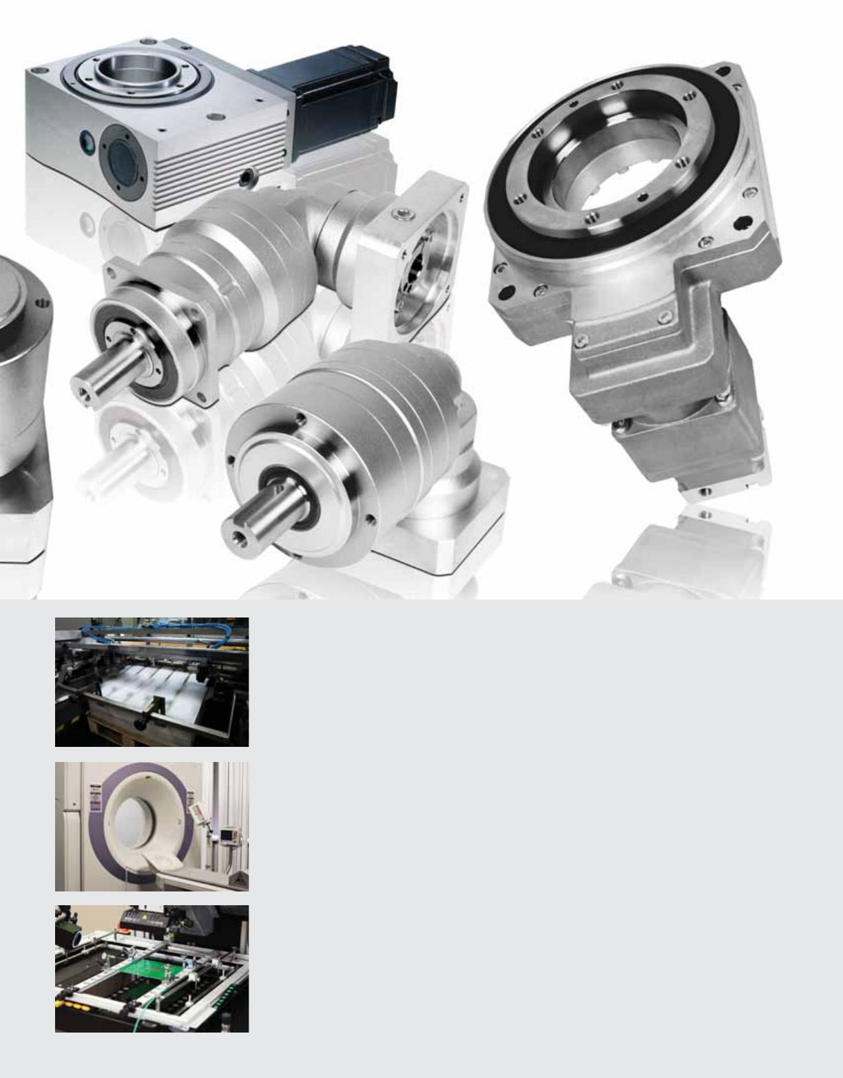
STATEOFTHEART TECHNOLOGY

Manufacturing Strength and Capabilities
As mentioned previously, NIDECSHIMPO has a state-
of-the-art manufacturing plant located about miles
south of Shanghai in an industrial park in the Zheijang
province. The industrial park is the home to more than
NIDEC Group Company manufacturing plants, making
NIDEC a very important employer for the local commu-
nity. NIDEC is one of the rst Japanese corporations to fo-
cus on establishing local manufacturing capabilities and
a strong supply chain networks in China, as an important
part of their strategy.
The primary NIDECSHIMPO manufacturing facility is
now producing more than , reducers a month. The
plant has achieved large scale production and econo-
mies of scale that is a major advantage over our competi-
tors. This manufacturing strength allows NIDECSHIMPO
to provide unmatched value to our OEM customers,
helping them to compete in a very price competitive
global market.
NIDECSHIMPO has been very successful over the past
decade at bringing new high performance and high
quality products to the market. We have developed a
core competency at quickly developing products and
applying our know-how to e ciently scale-up a manu-
facturing process from bench testing to large volume
production. We promise to leverage this intrinsic skill set
in order to continue to push the product development
envelope and provide even higher performance, cost-
e ective products to our customers.

Noise Measurment
Shock Load Testing
Backlash Measurement
Load Testing
Quality Control Program
Our high-volume and cost e ective manufacturing capa-
bilities would be meaningless if we did not have the appro-
priate quality control program in place. NIDECSHIMPO
takes great pride in our product quality, and we have im-
plemented numerous tests and metrics in order to insure
our products exceed our customers’ expectations.
Every reducer that leaves our manufacturing plant under-
goes a series of performance tests before it’s cleared for
shipment. It is not satisfactory for NIDECSHIMPO to sim-
ply conduct lot testing. Each reducer is tested under ex-
treme duty cycle and duration simulated environments.
The program includes the following tests – Noise Mea-
surement, Continuous Load Testing, Shock Load Testing,
and a Backlash Measurement Check. Besides nal assem-
bly performance testing, a quality control program is in
place for any raw materials entering our manufacturing
plant. This testing at the front end of our production pro-
cess is crucial, and our quality inspections at the point-of-
entry are as stringent as any testing done throughout our
manufacturing process.

Americas Kit Assembly Center
In , NIDECSHIMPO AMERICA launched a kit build
program at their Itasca, IL facility to serve the North
American market. The new Kit Build Center allows
NIDECSHIMPO to quickly assemble a larger variety
of high-precision planetary reducers, which surpasses
all competition. The Kit Build Center can assemble any
inline series (VRL, VRB, VRS) of reducers in most major
ratios within a to day period. The larger frame sizes,
especially the right-angle products are shipped from Ja-
pan within a week period.
The Kit Build Center tests every assembled planetary
reducer to make sure all performance speci cations are
met. The battery of tests includes load testing, noise
measurement, and backlash measurement, the same
tests run by our manufacturing facility. The new Kit Build
Center provides an excellent, quick, turn-around solu-
tion for Distributors working on single projects, OEMs
requiring prototype units for test, and basic aftermarket
support where required.
For more information about the Kit Build Center in North
America, please contact your local NIDECSHIMPO sales
o ce. Take advantage of the quick turn-around time in
order to stay out in front of your competition. Contact
NIDECSHIMPO today!

The Kit Assembly Cycle
SHIMPO overseas factory
high volume manufacturing
Streamlined replenishment of
parts from factory overseas
E cient inventory
of subassemblies &
parts in Itasca, IL
Complete gearbox assembly
& testing in Itasca, IL
Large variety, fast delivery at
the most competitive price
The kit assembly cycle requires clear communication and coordination between all parties in-
volved at every stage of the cycle. If quality control is slighted at any stage, the kit assembly
program will not maintain the high-level of performance our customers expect from our prod-
ucts. At every stage, NIDECSHIMPO makes e cient communication and stringent control pro-
cedures priority number one.

Product Series VRSF VRL VRB VRS VRT ER
Catalog Page 14 32 80 126 172 408
Axis of Orientation Coaxial Coaxial Coaxial Coaxial Coaxial Coaxial
Gear Description Planetary helical Planetary helical Planetary helical Planetary helical Planetary helical Cycloidal
Frame
Smallest B (60mm) 070 060 060 064 B03
Largest E (170mm) 235 220 240 285 F07
Variety4667710
Ratio
Minimum 3 333411
Maximum 81 100 100 100 100 71
Variety 9 22 22 22 19 7
Installation
Rounded, Tapping Holes on Casing ■
Square, Through Holes on Casing ■■■
Rounded, Through Holes on Casing ■■**
Lubrication
Grease ■■■■■■
Oil ■
Input
Direct Clamp ■■■■■■
Keyed Shaft ■
Output
Smooth Shaft with Tapping Hole ■■■■
Shaft with Tapping Hole and Keyway ■■■■
Flanged Connection ■■**
Flange with Hollow Bore
Bearing Type on Output
Ball Bearing ■■■ ■■
Tapered Roller Bearing ■■■
Cross Roller Bearing
Performance Speci cation
Radial Load Ordinary Ordinary Excellent Excellent Ordinary
Thrust Load Ordinary Ordinary Excellent Excellent Ordinary
Backlash Rating < 1 arc-min
≤ 2 arc-min
≤ 3 arc-min ■■■■
≤ 5 arc-min ■■
≤ 6 arc-min ■
≤ 8 arc-min
≤ 9 arc-min
≤ 10 arc-min
≤ 11 arc-min
≤ 15 arc-min ■
≤ 30 arc-min
Torsional Rigidity Ordinary Ordinary Ordinary Excellent Excellent Excellent
E ciency Excellent Excellent Excellent Excellent Excellent Excellent
Gear Reducer Selection Overview

Product Series NEV EVL EVB EVS STH STR
Catalog Page 224 244 284 324 370 378
Axis of Orientation Right-angle Right-angle Right-angle Right-angle O -set rotary stage Right-angle
Gear Description Planetary helical Spiral bevel/Planetary Spiral bevel/Planetary Spiral bevel/Planetary Planetary w/ Rotary stage Roller gear /cam mechanism
Frame
Smallest B (60mm) 070 060 060 052 (B frame) 040
Largest E (170mm) 235 220 240 078 (C frame) 240
Variety466727
Ratio
Minimum 3 3 3 3 12 15
Maximum 81 100 100 100 324 Various*
Variety 9 22 22 22 9 Various*
Installation
Rounded, Tapping Holes on Casing ■
Square, Through Holes on Casing ■■■
■*
Rounded, Through Holes on Casing ■
Lubrication
Grease ■■■■■
Oil
Input
Direct Clamp ■■■■■
■*
Keyed Shaft
Output
Smooth Shaft with Tapping Hole ■■■■
Shaft with Tapping Hole and Keyway ■■■■
Flanged Connection
Flange with Hollow Bore ■■■
Bearing Type on Output
Ball Bearing ■■■
Tapered Roller Bearing ■
Cross Roller Bearing ■■
Performance Speci cation
Radial Load Ordinary Ordinary Ordinary Excellent Ordinary Excellent
Thrust Load Ordinary Ordinary Ordinary Excellent Excellent Excellent
Backlash Rating < 1 arc-min
≤ 2 arc-min ■
≤ 3 arc-min
≤ 5 arc-min ■
≤ 6 arc-min ■■■
≤ 8 arc-min
≤ 9 arc-min ■■■
≤ 10 arc-min ■
≤ 11 arc-min
≤ 15 arc-min
≤ 30 arc-min ■
Torsional Rigidity Ordinary Ordinary Ordinary Excellent Ordinary Excellent
E ciency Excellent Excellent Excellent Excellent Excellent Ordinary
NOTE: *(STR) motor connection to VRB/EVB reducer **(ER) several mounting styles available

SHIMPO ABLE Gear Reducers
Industrial Areas of Expertise
Machine Tool and Metal Forming
A selection of robust and durable speed reducers, both planetary and cycloidal, for heavi-
er duty or high shock load applications. Many choices for the di erent levels of precision,
torque ratings, and mounting options required on the di erent axes of movement.
Custom Assembly and Test Automation
A wide variety of frame sizes and ratios are available for immediate delivery to solve any
inertia matching application within turn-key projects. The hollow-bore rotary products and
planetary reducers with high torsional rigidity characteristics are ideal for many indexing
applications.
Packaging and Filling Machinery
An assortment of inline and right angle speed reducers at di erent price points, depending
on the speci cations needed. For the OEM, this provides ideal, cost-e ective, gear reduction
solutions for exported packaging equipment or applications where you are transitioning
from induction motor or hydraulics to servo motor technology.
Printing and Converting Equipment
Our reducers are designed to minimize the heat generated, and they are therefore capable
of operating at higher speeds and within continuous duty environments. An assortment of
size and ratio combinations are available that allow proper selection to maximize operating
e ciency for varying cycle speeds.
Medical and Health Care Related Systems
We o er extremely accurate positioning characteristics and high quality gear reducers that
maintain a level of performance consistency required in medical applications. Our inline
speed reducers are ideal for commercial equipment applications involving pumping, mo-
bile equipment, and smooth positioning.
Semiconductor and Circuit Manufacturing
A broad o ering of high precision, clean room friendly planetary and hollow-bore rotary re-
ducers that are preferable over belt drives and other reduction methods that can introduce
contamination. Custom coatings and materials are available for OEM applications when nec-
essary for corrosive chamber environments and di erent clean room classi cations.

VRSF-SERIES
The intelligent selection for a higher performance planetary gear-
box at an ultimate value for standard duty motion control ap-
plications. The VRSF utilizes a lightweight aluminum frame, helical
cut gear, and bearing span that provides the best level of precision
and torque carrying capacity in its competitive class. The noise level
generated by the VRSF is greatly reduced in comparison to any other
competitor's economy class series that relies on spur gearing. The
VRSF can be selected with one of three backlash levels – Standard
backlash at arc/min, Reduced backlash at arc/min, and Precision
backlash at arc/min.
The series is available in four frame sizes (B, C, D, E) which has a peak
output torque of Nm across a variety of ratios. The VRSF is the ideal
choice for OEMs manufacturing in larger volume and where accuracy
is important and duty cycle is not overly extreme. The VRSF has been
very popular in applications such as mobile robotics, standard packag-
ing machinery, medical equipment, and other types of enclosed food
processing applications.

VRSF-SERIES
■Quiet operation: Helical cut gears contribute to reduced vibration and noise
■Di erent precision levels available in order to choose the best t and value
■High rigidity & torque: Rigidity and torque capacity are achieved by using uncaged needle
roller bearings
■Adapter bushing connection: Enables a simple, e ective attachment to most servo motors
■Extremely light weight aluminum body to reduce excess weight from your equipment
■Additional features include NEMA output ange options
VRSF

VRSF-SERIES Inline shaft
2
1
VRSF-Series Features
1 High-precision with backlash .° (three arc-minutes), Low-backlash .° ( ve arc-minutes) or
less certi ed
2 Smooth rotation and less pulsation due to utilizing helical gearing
3 Maintenance free with long-life grease, the sealed structure allows for mounting in any orientation
4 Every possible countermeasure against oil leakage taken: Including impregnation of the case and
air leak test
5 IP65 rating extremely popular in washdown and food grade environments
6 Various optional features allowed, such as di erent coatings, plating, and grease varieties
6
3

VRSF
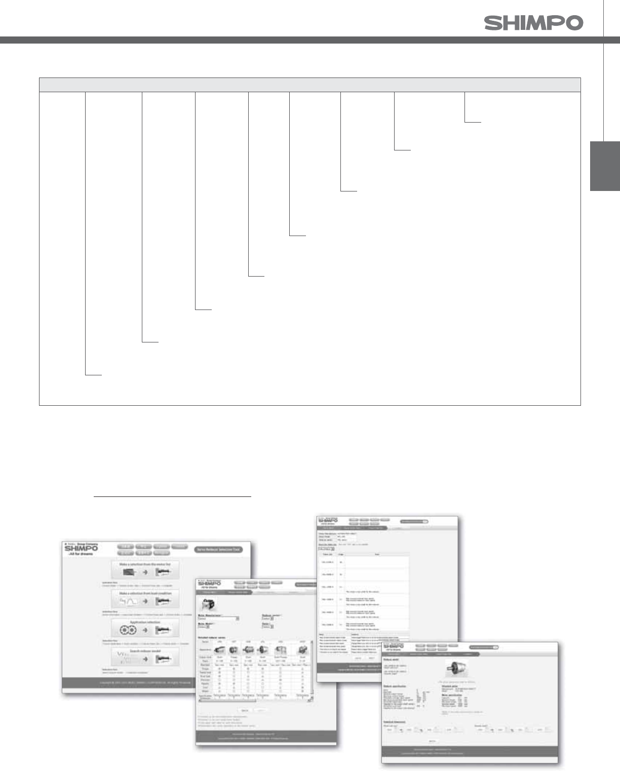
VRSF-Series Model Code
Contact us for additional information or refer to our online reducer selection tool.
Selection tool www.nidec-shimpo.co.jp/selection/eng
Reducer frame size: B, C, D, E
Mount code (*1)
VR
FS--15
Ratio
Backlash specication
Backlash*
1stage: 3, 5, S9
2stage: 15, 20, 25, 35, 45, 81
Output specication
(The motor shaft is provided without key-way, but can be used with a keyed motor shaft.)
Model name for ABLE reducer
C - 19HB16
Symbol: Standard
PB: High-precision
F: F-ange - Installation style is not limited
LB: Low-backlash
Input selection Clamp collar
Adapter
Bushing
SHIMPO’s adapter ange
motor mounting methodology
allows for nearly limitless
motor mounting options
* 1) Mount code varies depending on the motor.
Please refer to reducer selection tool or contact us for more information.
Output shaft tapping
B frame: M5 × 10 C frame: M6 × 12 D frame: M8 × 16 E frame: M10 × 20
Frame Size (Standard)
VR- VR-LB VR-PB
(Low-Backlash) (High-Precision)
B frame
C frame
D frame
E frame
15 arc-minutes
15 arc-minutes
15 arc-minutes
15 arc-minutes
10 arc-minutes 3 arc-minutes
3 arc-minutes
3 arc-minutes
3 arc-minutes
*Values obtained by multiplying the output shaft speed by a load of ±5% of allowable output torque.
5 arc-minutes
5 arc-minutes
5 arc-minutes
Refer to page - for Metric and NEMA Output Flange
Metric and NEMA Output Flange

VRSF-SERIES Inline shaft
VRSF B-Frame 1-Stage and 2-Stage Specifications
Frame Size B
Stage 1-Stage 2-Stage
Ratio Units Note 3 5 9 15 20 25 35
Nominal Output Torque [Nm] -- 3.43 2.84 2.35 4.02 5.00 6.27 3.84
Maximum Acceleration Torque [Nm] -- 10.3 8.53 7.25 12.2 15.0 19.0 11.5
Emergency Stop Torque [Nm] -- -- -- -- -- -- -- --
Nominal Input Speed [rpm] -- 3000 3000
Maximum Input Speed [rpm] *1 5000 5000
No Load Running Torque [Nm] -- 0.119 0.048
Permitted Radial Load [N] *2 392 490 588 784 804 882 882
Permitted Axial Load [N] *3 196 245 294 392 402 441 441
Moment of Inertia (≤Ø 8) [kgcm2] *4 0.081 0.059 0.052 0.057 0.056 0.056 0.052
Moment of Inertia (≤Ø 14) [kgcm2] *4 0.150 0.130 0.120 0.130 0.130 0.130 0.120
E ciency [%] -- 90 85
Torsional Rigidity [Nm/arcmin] -- 0.8 0.8
Backlash (Standard) [Arc-min] -- ≤ 15 ≤ 15
Backlash (Low) [Arc-min] -- ≤ 10 ≤ 10
Backlash (Precision) [Arc-min] -- ≤ 3 ≤ 3
Noise Level [dB] -- ≤ 72 ≤ 65
Protection Class -- -- IP65 IP65
Ambient Temperature [°C] -- 0-40 0-40
Permitted Housing Temperature [°C] -- 90 90
Weight (≤Ø 8) [kg] *5 0.58 0.75
Weight (≤Ø 14) [kg] *5 0.7 0.86
*1) Nominal input speed is , rpm or less
*2) Permitted radial load is measured at the middle of the output shaft
*3) Permitted thrust load is measured at the center of the output shaft
*4) The moment of inertia is re ected to the input shaft of the reducer
*5) The weight varies slightly depending on the input bore size and reduction ratio
Refer to page - for Metric and NEMA Output Flange

VRSF
VRSF C-Frame 1-Stage and 2-Stage Specifications
Frame Size C
Stage 1-Stage 2-Stage
Ratio Units Note 3 5 9 15 20 25 35 45 81
Nominal Output Torque [Nm] -- 6.86 11.5 9.7 16.2 21.1 26.4 15.5 9.5 9.7
Maximum Acceleration Torque [Nm] -- 20.6 34.3 29.2 48.6 63.3 79.2 46.6 28.6 29.2
Emergency Stop Torque [Nm] -- -- -- -- -- -- -- -- -- --
Nominal Input Speed [rpm] -- 3000 3000
Maximum Input Speed [rpm] *1 5000 5000
No Load Running Torque [Nm] -- 0.29 0.19
Permitted Radial Load [N] *2 784 980 1180 1470 1570 1670 1670 1670 1670
Permitted Axial Load [N] *3 392 490 588 735 785 833 833 833 833
Moment of Inertia (≤Ø 8) [kgcm2] *4 -- -- -- 0.077 0.070 0.062 0.055 0.053 0.052
Moment of Inertia (≤Ø 14) [kgcm2] *4 0.630 0.380 0.300 0.150 0.140 0.130 0.130 0.120 0.120
-- -- *4 1.100 0.880 0.800 -- -- -- -- -- --
E ciency [%] -- 90 85
Torsional Rigidity [Nm/arcmin] -- 3 3
Backlash (Standard) [Arc-min] -- ≤ 15 ≤ 15
Backlash (Low) [Arc-min] -- ≤ 5 ≤ 5
Backlash (Precision) [Arc-min] -- ≤ 3 ≤ 3
Noise Level [dB] -- ≤ 72 ≤ 65
Protection Class -- -- IP 65 IP65
Ambient Temperature [°C] -- 0-40 0-40
Permitted Housing Temperature [°C] -- 90 90
Weight (≤Ø 8) [kg] *5 -- 1.8
Weight (≤Ø 14) [kg] *5 1.8 1.9
Weight (≤Ø 19) -- -- 2.2 --
*1) Nominal input speed is , rpm or less
*2) Permitted radial load is measured at the middle of the output shaft
*3) Permitted thrust load is measured at the center of the output shaft
*4) The moment of inertia is re ected to the input shaft of the reducer
*5) The weight varies slightly depending on the input bore size and reduction ratio
Refer to page - for Metric and NEMA Output Flange

VRSF-SERIES Inline shaft
VRSF D-Frame 1-Stage and 2-Stage Specifications
*1) Nominal input speed is , rpm or less
*2) Permitted radial load is measured at the middle of the output shaft
*3) Permitted thrust load is measured at the center of the output shaft
*4) The moment of inertia is re ected to the input shaft of the reducer
*5) The weight varies slightly depending on the input bore size and reduction ratio
Frame Size D
Stage 1-Stage 2-Stage
Ratio Units Note 3 5 9 15 20 25 35 45 81
Nominal Output Torque [Nm] -- 18.3 23.5 18.2 30.4 40.6 50.7 37 28.3 17.8
Maximum Acceleration Torque [Nm] -- 54.9 70.6 54.7 91.2 122 152 111 85.2 53.5
Emergency Stop Torque [Nm] -- -- -- -- -- -- -- -- -- --
Nominal Input Speed [rpm] -- 3000 3000
Maximum Input Speed [rpm] *1 5000 5000
No Load Running Torque [Nm] -- 0.51 0.26
Permitted Radial Load [N] *2 882 1080 1470 1760 1910 2060 2060 2060 2060
Permitted Axial Load [N] *3 441 539 735 882 955 1030 1030 1030 1030
Moment of Inertia (≤Ø 8) [kgcm2] *4 -- -- -- -- -- -- -- -- 0.10
Moment of Inertia (≤Ø 14) [kgcm2] *4 1.30 0.59 0.38 0.37 0.35 0.34 0.30 0.29 0.29
Moment of Inertia (≤Ø 19) [kgcm2] *4 1.80 1.10 0.90 0.86 0.84 0.83 0.79 0.78 0.77
Moment of Inertia (≤Ø 28) [kgcm2] *4 3.60 2.90 2.70 2.70 2.70 2.70 -- -- --
E ciency [%] -- 90 85
Torsional Rigidity [Nm/arcmin] -- 6 6
Backlash (Standard) [Arc-min] -- ≤ 15 ≤ 15
Backlash (Low) [Arc-min] -- ≤ 5 ≤ 5
Backlash (Precision) [Arc-min] -- ≤ 3 ≤ 3
Noise Level [dB] -- ≤ 72 ≤ 65
Protection Class -- -- IP65 IP65
Ambient Temperature [°C] -- 0-40 0-40
Permitted Housing Temperature [°C] -- 90 90
Weight (≤Ø 8) [kg] *5 -- 2.8
Weight (≤Ø 14) [kg] *5 2.8 3.3
Weight (≤Ø 19) [kg] *5 3.2 3.7
Weight (≤Ø 28) [kg] *5 4.0 4.8
Refer to page - for Metric and NEMA Output Flange

VRSF
VRSF E-Frame 1-Stage and 2-Stage Specifications
*1) Nominal input speed is , rpm or less
*2) Permitted radial load is measured at the middle of the output shaft
*3) Permitted thrust load is measured at the center of the output shaft
*4) The moment of inertia is re ected to the input shaft of the reducer
*5) The weight varies slightly depending on the input bore size and reduction ratio
Frame Size E
Stage 1-Stage 2-Stage
Ratio Units Note 3 5 9 15 20 25 35 45 81
Nominal Output Torque [Nm] -- 44.1 56.8 73.5 91.4 78.4 65.4 71 91.3 43.3
Maximum Acceleration Torque [Nm] -- 132 171 221 274 235 196 213 274 130
Emergency Stop Torque [Nm] -- -- -- -- -- -- -- -- -- --
Nominal Input Speed [rpm] -- 3000 3000
Maximum Input Speed [rpm] *1 5000 5000
No Load Running Torque [Nm] -- 1.12 0.62
Permitted Radial Load [N] *2 1370 1670 1960 2350 2500 2650 3430 3520 3530
Permitted Axial Load [N] *3 686 833 980 1180 1250 1320 1715 1760 1765
Moment of Inertia (≤Ø 8) [kgcm2] *4 -- -- 0.61 0.63 0.56 0.53 0.40 0.35 0.34
Moment of Inertia (≤Ø 14) [kgcm2] *4 4.40 1.90 1.20 1.10 1.10 1.00 0.90 0.85 0.84
Moment of Inertia (≤Ø 19) [kgcm2] *4 6.20 3.70 2.90 3.30 3.20 3.20 2.80 2.70 2.70
Moment of Inertia (≤Ø 28) [kgcm2] *4 14.00 11.00 11.00 11.00 11.00 11.00 -- -- --
E ciency [%] -- 90 85
Torsional Rigidity [Nm/arcmin] -- 20 20
Backlash (Standard) [Arc-min] -- ≤ 15 ≤ 15
Backlash (Low) [Arc-min] -- ≤ 5 ≤ 5
Backlash (Precision) [Arc-min] -- ≤ 3 ≤ 3
Noise Level [dB] -- ≤ 75 ≤ 75
Protection Class -- -- IP65 IP65
Ambient Temperature [°C] -- 0-40 0-40
Permitted Housing Temperature [°C] -- 90 90
Weight (≤Ø 8) [kg] *5 6.1 7.1
Weight (≤Ø 14) [kg] *5 6.5 7.5
Weight (≤Ø 19) [kg] *5 7.4 9.3
Weight (≤Ø 28) [kg] *5 9.8 11.7
Refer to page - for Metric and NEMA Output Flange

VRSF-SERIES Inline shaft
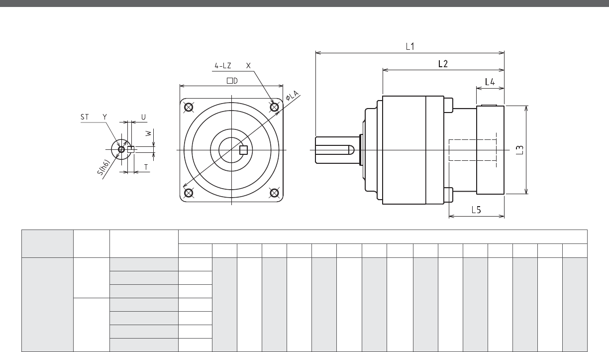
VRSF B-Frame 1-Stage and 2-Stage Dimensions
depth
depth
Frame Size Ratio* Input Bore Dia.
E**
Dimensions
L*** LR S ST Y Q QM QK W×U T D LB LE LA LZ X
B
1-Stage
≦ φ8 104.5
32 12 M5 10 20 18 16 4×2.5 4 52 50 3 60 M5 12
≦φ14 107.5
2-Stage
≦φ8 115.5
≦φ14 118.5
*1) Single reduction : / - /S, Double reduction : / - / (/ - / for B frame)
*2) Bushing will be inserted to adapt to motor shaft

VRSF
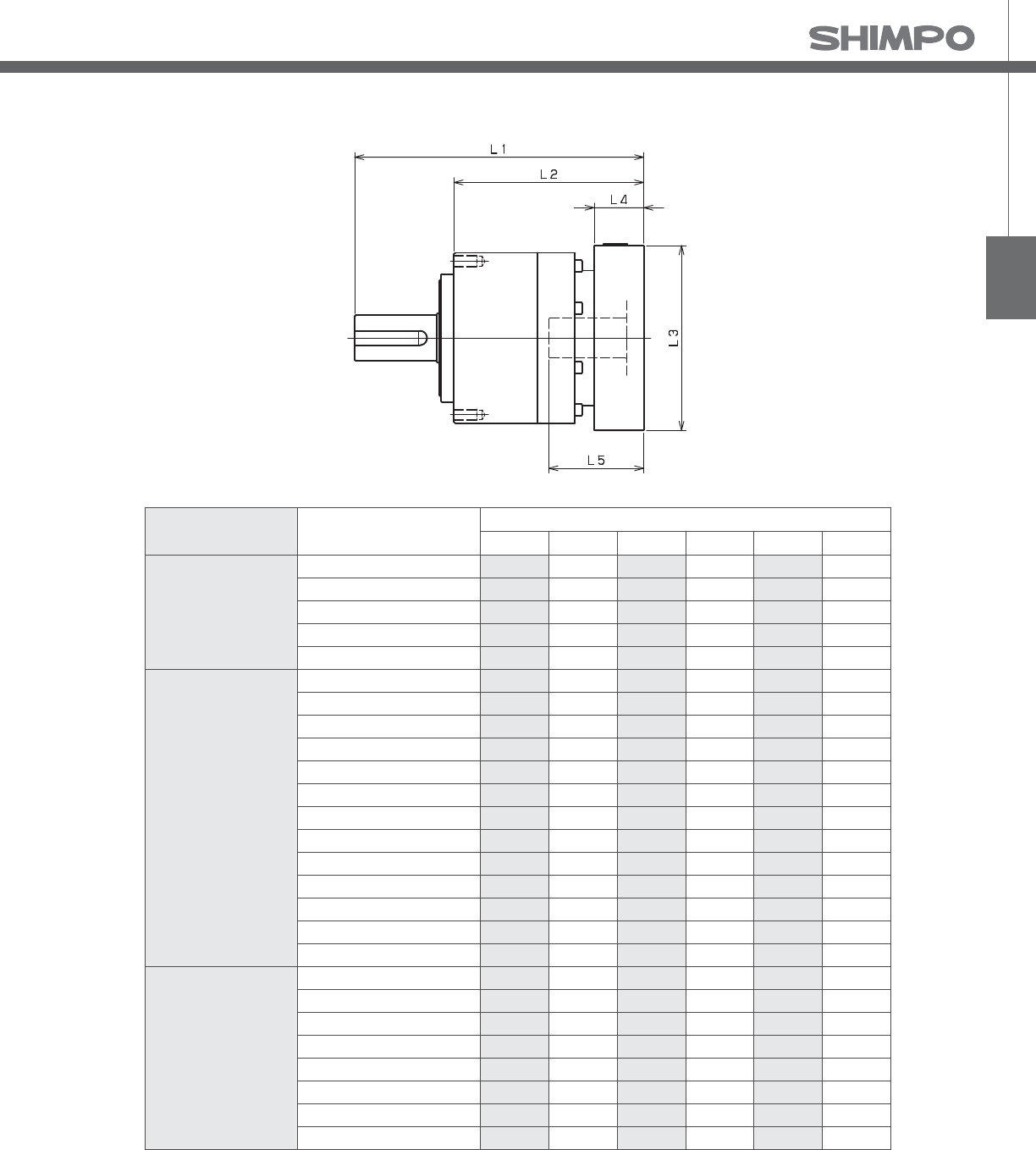
VRSF B-Frame 1-Stage and 2-Stage Adapter Dimensions
Model number **: Adapter code 1-Stage 2-Stage
L1 L2 L3 L4 L5 L1 L2 L3 L4 L5
VRSF-□-□B-8**
(Input shaft bore ≦ φ8)
AA•AC•AD•AF•AG•AL•AM•AN•AQ 104.5 72.5 □52 15.5 32 115.5 83.5 □52 15.5 32
AB•AE•AH•AJ•AK 109.5 77.5 □52 20.5 37 120.5 88.5 □52 20.5 37
BA•BB•BD•BE•BG•BH•BJ 104.5 72.5 □60 15.5 32 115.5 83.5 □60 15.5 32
BC•BF 109.5 77.5 □60 20.5 37 120.5 88.5 □60 20.5 37
CA 109.5 77.5 □70 20.5 37 120.5 88.5 □70 20.5 37
VRSF-□-□B-14**
(Input shaft bore ≦ φ14)
BA•BB•BD•BE•BF•BG•BH•BJ•BK•BP 107.5 75.5 □65 16.5 35 118.5 86.5 □65 16.5 35
BC•BH•BM•BN 112.5 80.5 □65 21.5 40 123.5 91.5 □65 21.5 40
BL 117.5 85.5 □65 26.5 45 128.5 96.5 □65 26.5 45
CA•CC 107.5 75.5 □70 16.5 35 118.5 86.5 □70 16.5 35
CB 112.5 80.5 □70 21.5 40 123.5 91.5 □70 21.5 40
DA•DB•DC•DD•DF•DH•DJ 107.5 75.5 □80 16.5 35 118.5 86.5 □80 16.5 35
DE•DL 112.5 80.5 □80 21.5 40 123.5 91.5 □80 21.5 40
DG•DK 117.5 85.5 □80 26.5 45 128.5 96.5 □80 26.5 45
EA•EB•EC•EF•EG•EK•EL 107.5 75.5 □90 16.5 35 118.5 86.5 □90 16.5 35
EJ•EM 112.5 80.5 □90 21.5 40 123.5 91.5 □90 21.5 40
ED•EE•EH 117.5 85.5 □90 26.5 45 128.5 96.5 □90 26.5 45
FA 107.5 75.5 □100 16.5 35 118.5 86.5 □100 16.5 35
FB 107.5 75.5 □115 16.5 35 118.5 86.5 □115 16.5 35
*1) Single reduction : / - /S, Double reduction : / - /
*2) Bushing will be inserted to adapt to motor shaft
A more comprehensive adapter ange o ering can be found using the NIDECSHIMPO Online Selector Tool. The variety is constantly expanding and being
updated on the Selector Tool. If you have any questions or need any support, contact NIDECSHIMPO.
For an explanation on the Adapter Flange Code, please turn to page .

VRSF-SERIES Inline shaft
VRSF C-Frame 1-Stage and 2-Stage Dimensions
depth
depth
Frame Size Ratio* Input Bore Dia.
E**
Dimensions
L*** LR S ST Y Q QM QK W×U T D LB LE LA LZ X
C
1-Stage
≦ φ14 140
50 19 M6 12 30 26 22 6×3.5 6 78 70 3 90 M6 20
≦ φ19 156
2-Stage
≦ φ8 147.5
≦ φ14 150.5
*1) Single reduction : / - /S, Double reduction : / - / (/ - / for B frame)
*2) Bushing will be inserted to adapt to motor shaft

VRSF
VRSF C-Frame 1-Stage and 2-Stage Adapter Dimensions
Model number **: Adapter code 1-Stage 2-Stage
L1 L2 L3 L4 L5 L1 L2 L3 L4 L5
VRSF-□-□C-8**
(Input shaft bore ≦ φ8)
AA•AC•AD•AF•AG•AL•AM•AN•AQ -- -- -- -- -- 147.5 97.5 □52 15.5 32
AB•AE•AH•AJ•AK -- -- -- -- -- 152.5 102.5 □52 20.5 37
BA•BB•BD•BE•BG•BH•BJ -- -- -- -- -- 147.5 97.5 □60 15.5 32
BC•BF -- -- -- -- -- 152.5 102.5 □60 20.5 37
CA -- -- -- -- -- 152.5 102.5 □70 20.5 37
VRSF-□-□C-14**
(Input shaft bore ≦ φ14)
BA•BB•BD•BE•BF•BG•BH•BJ•BK•BP 140 90 □65 16.5 35 150.5 100.5 □65 16.5 35
BC•BH•BM•BN 145 95 □65 21.5 40 155.5 105.5 □65 21.5 40
BL 150 100 □65 26.5 45 160.5 110.5 □65 26.5 45
CA•CC 140 90 □70 16.5 35 150.5 100.5 □70 16.5 35
CB 145 95 □70 21.5 40 155.5 105.5 □70 21.5 40
DA•DB•DC•DD•DF•DH•DJ 140 90 □80 16.5 35 150.5 100.5 □80 16.5 35
DE•DL 145 95 □80 21.5 40 155.5 105.5 □80 21.5 40
DG•DK 150 100 □80 26.5 45 160.5 110.5 □80 26.5 45
EA•EB•EC•EF•EG•EK•EL 140 90 □90 16.5 35 150.5 100.5 □90 16.5 35
EJ•EM 145 95 □90 21.5 40 155.5 105.5 □90 21.5 40
ED•EE•EH 150 100 □90 26.5 45 160.5 110.5 □90 26.5 45
FA 140 90 □100 16.5 35 150.5 100.5 □100 16.5 35
FB 140 90 □115 16.5 35 150.5 100.5 □115 16.5 35
VRSF-□-□C-19**
(Input shaft bore ≦ φ19)
DA•DB•DC 156 106 □80 25 50 -- -- -- -- --
DD 166 116 □80 35 60 -- -- -- -- --
DE 161 111 □80 30 55 -- -- -- -- --
EA 161 111 □90 30 55 -- -- -- -- --
EB•ED 156 106 □90 25 50 -- -- -- -- --
EC 166 116 □90 35 60 -- -- -- -- --
FA 156 106 □100 25 50 -- -- -- -- --
FB 166 116 □100 35 60 -- -- -- -- --
GA•GC•GH 161 111 □115 30 55 -- -- -- -- --
GB•GD•GJ 156 106 □115 25 50 -- -- -- -- --
GE•GF 166 116 □115 35 60 -- -- -- -- --
HA 156 106 □130 25 50 -- -- -- -- --
HB 171 121 □130 40 65 -- -- -- -- --
HC•HD•HE 161 111 □130 30 55 -- -- -- -- --
JA 166 116 □150 35 60 -- -- -- -- --
JB 171 121 □150 40 65 -- -- -- -- --
*) Single reduction : / - /S, Double reduction : / - /
A more comprehensive adapter ange o ering can be found using the NIDECSHIMPO Online Selector Tool. The variety is constantly expanding and being
updated on the Selector Tool. If you have any questions or need any support, contact NIDECSHIMPO.
For an explanation on the Adapter Flange Code, please turn to page .
*) Bushing will be inserted to adapt to motor shaft
VRSF-SERIES Inline shaft
Frame Size Ratio* Input Bore Dia.
E**
Dimensions
L*** LR S ST Y Q QM QK W×U T D LB LE LA LZ X
D
1-Stage
≦ φ14 155
61 24 M8 16 40 35 30 8×4 7 98 90 5 115 M8 20
≦ φ19 171
≦ φ28 186
2-Stage
≦ φ8 163
≦ φ14 169
≦ φ19 184
≦ φ28 200.5
*1) Single reduction : / - /S, Double reduction : / - / (/ - / for B frame)
*2) Bushing will be inserted to adapt to motor shaft
VRSF D-Frame 1-Stage and 2-Stage Dimensions
depth
depth

VRSF
VRSF D-Frame 1-Stage and 2-Stage Adapter Dimensions
Model number **: Adapter code 1-Stage 2-Stage
L1 L2 L3 L4 L5 L1 L2 L3 L4 L5
VRSF-□-□D-8**
(Input shaft bore ≦ φ8)
AA•AC•AD•AF•AG•AL•AM•AN•AQ -- -- -- -- -- 163 102 □52 15.5 32
AB•AE•AH•AJ•AK -- -- -- -- -- 168 107 □52 20.5 37
BA•BB•BD•BE•BG•BH•BJ -- -- -- -- -- 163 102 □60 15.5 32
CA -- -- -- -- -- 168 107 □70 20.5 37
VRSF-□-□D-14**
(Input shaft bore ≦ φ14)
BA•BB•BD•BE•BF•BG•BH•BJ•BK•BP 155 94 □65 16.5 35 169 108 □65 16.5 35
BC•BH•BM•BN 160 99 □65 21.5 40 174 113 □65 21.5 40
CA•CC 155 94 □70 16.5 35 169 108 □70 16.5 35
DA•DB•DC•DD•DF•DH•DJ 155 94 □80 16.5 35 169 108 □80 16.5 35
EA•EB•EC•EF•EG•EK•EL 155 94 □90 16.5 35 169 108 □90 16.5 35
FA 155 94 □100 16.5 35 169 108 □100 16.5 35
FB 165 104 □100 26.5 45 179 118 □100 26.5 45
JA 170 109 □150 31.5 50 184 123 □115 31.5 50
VRSF-□-□D-19**
(Input shaft bore ≦ φ19)
DA•DB•DC 171 110 □80 25 50 184 123 □80 25 50
EB•ED 171 110 □90 25 50 184 123 □90 25 50
FA 171 110 □100 25 50 184 123 □100 25 50
FB 181 120 □100 35 60 194 133 □100 35 60
GB•GD•GJ 171 110 □115 25 50 184 123 □115 25 50
HA 171 110 □130 25 50 184 123 □130 25 50
HB 186 125 □130 40 65 199 138 □130 40 65
HC•HD•HE 176 115 □130 30 55 189 128 □130 30 55
JA 181 120 □150 35 60 194 133 □150 35 60
JB 186 125 □150 40 65 199 138 □150 40 65
VRSF-□-□D-28**
(Input shaft bore ≦ φ28)
FA•FB•FC 186 125 □100 35 67 200.5 139.5 □100 35 67
FD•FE 181 120 □100 30 62 195.5 134.5 □100 30 62
GA•GB•GC•GD•GE•GF•GG•GH 186 125 □115 35 67 200.5 139.5 □115 35 67
HA•HC•HD 186 125 □130 35 67 200.5 139.5 □130 35 67
HB 196 135 □130 45 77 210.5 149.5 □130 45 77
HE 201 140 □130 50 82 215.5 154.5 □130 50 82
HF 181 120 □130 30 62 195.5 134.5 □130 30 62
JA•JB•JC•JF 186 125 □150 35 67 200.5 139.5 □150 35 67
JD 206 145 □150 55 87 220.5 159.5 □150 55 87
JE 210.5 149.5 □150 45 77 210.5 149.5 □150 45 77
KA•KB 186 125 □180 35 67 200.5 139.5 □180 35 67
KD 196 135 □180 45 77 210.5 149.5 □180 45 77
*) Single reduction : / - /S, Double reduction : / - /
A more comprehensive adapter ange o ering can be found using the NIDECSHIMPO Online Selector Tool. The variety is constantly expanding and being
updated on the Selector Tool. If you have any questions or need any support, contact NIDECSHIMPO.
For an explanation on the Adapter Flange Code, please turn to page .
*) Bushing will be inserted to adapt to motor shaft

VRSF-SERIES Inline shaft
Frame Size Ratio* Input Bore Dia.
E**
Dimensions
L*** LR S ST Y Q QM QK W×U T D LB LE LA LZ X
E
1-Stage
≦ φ14 189
75 32 M10 20 55 52 45 10×5 8 125 110 5 135 M10 20
≦ φ19 198.5
≦ φ28 224
≦ φ38 240
2-Stage
≦ φ14 210
≦ φ19 225
≦ φ28 246.5
≦ φ38 261.5
*1) Single reduction : / - /S, Double reduction : / - / (/ - / for B frame)
*2) Bushing will be inserted to adapt to motor shaft
VRSF E-Frame 1-Stage and 2-Stage Dimensions
depth
depth

VRSF
VRSF E-Frame 1-Stage and 2-Stage Adapter Dimensions
Model number **: Adapter code 1-Stage 2-Stage
L1 L2 L3 L4 L5 L1 L2 L3 L4 L5
VRSF-□-□E-14**
(Input shaft bore ≦ φ14)
BA•BB•BD•BE•BF•BG•BH•BJ•BK•BP 189 114 □ 65 16.5 35 210 135 □65 16.5 35
BC•BH•BM•BN 194 119 □65 21.5 40 215 140 □65 21.5 40
CA•CC 189 114 □70 16.5 35 210 135 □70 16.5 35
DA•DB•DC•DD•DF•DH•DJ 189 114 □80 16.5 35 210 135 □80 16.5 35
EA•EB•EC•EF•EG•EK•EL 189 114 □90 16.5 35 210 135 □90 16.5 35
FA 189 114 □100 16.5 35 210 135 □100 16.5 35
FB 199 124 □100 26.5 45 220 145 □100 26.5 45
JA 204 129 □150 31.5 50 225 150 □150 31.5 50
VRSF-□-□E-19**
(Input shaft bore ≦ φ19)
DA•DB•DC 198.5 123.5 □80 25 50 225 150 □80 25 50
EB•ED 198.5 123.5 □90 25 50 225 150 □90 25 50
FA 198.5 123.5 □100 25 50 225 150 □100 25 50
FB 208.5 133.5 □100 35 60 235 160 □100 35 60
GB•GD•GJ 198.5 123.5 □115 25 50 225 150 □115 25 50
HA 198.5 123.5 □130 25 50 225 150 □130 25 50
HB 213.5 138.5 □130 40 65 240 165 □130 40 65
JA 208.5 133.5 □150 35 60 235 160 □150 35 60
VRSF-□-□ E-28**
(Input shaft bore ≦ φ28)
FA•FB•FC 224 149 □100 35 67 246.5 171.5 □100 35 67
GA•GB•GC•GD•GE•GF•GG•GH 224 149 □115 35 67 246.5 171.5 □115 35 67
HA•HC•HD 224 149 □130 35 67 246.5 171.5 □130 35 67
HB 234 159 □130 45 77 256.5 181.5 □130 45 77
HF 119 144 □130 30 62 241.5 166.5 □130 30 62
JA•JB•JC•JF 224 149 □150 35 67 246.5 171.5 □150 35 67
KA•KB•KE 224 149 □180 35 67 246.5 171.5 □180 35 67
LA 224 149 □200 35 67 246.5 171.5 □200 35 67
LB 234 159 □200 45 77 256.5 181.5 □200 45 77
MA 224 149 □220 35 67 246.5 171.5 □220 35 67
MB 234 159 □220 45 77 256.5 181.5 □220 45 77
VRSF-□-□E-38**
(Input shaft bore ≦ φ38)
HA 240 165 □130 45 82 261.5 186.5 □130 45 82
HB•HE 235 160 □130 40 77 256.5 181.5 □130 40 77
JA 240 165 □150 45 82 261.5 186.5 □150 45 82
KA•KB•KC 240 165 □180 45 82 261.5 186.5 □180 45 82
KD 275 200 □180 80 117 296.5 221.5 □180 80 117
KE 255 180 □180 60 97 276.5 201.5 □180 60 97
MA•MB 240 165 □220 45 82 261.5 186.5 □220 45 82
*) Single reduction : / - /S, Double reduction : / - /
A more comprehensive adapter ange o ering can be found using the NIDECSHIMPO Online Selector Tool. The variety is constantly expanding and being
updated on the Selector Tool. If you have any questions or need any support, contact NIDECSHIMPO.
For an explanation on the Adapter Flange Code, please turn to page .
*) Bushing will be inserted to adapt to motor shaft

VRSF-SERIES Inline shaft
FB(h7)
FR
FE
FG
FC
FA Output Flange
4-FZ
VRSF Optional Metric Output Flange
Frame Size FG FR FE FB FC FA FZ
Bmm 8 24 3 50 75 65 6
inch 0.315 0.945 0.118 1.969 2.953 2.559 0.236
Cmm 12 33 3 72 110 95 7
inch 0.472 1.299 0.118 2.835 4.331 3.74 0.276
Dmm 13 48 5 90 134 115 8.8
inch 0.512 1.89 0.197 3.543 5.276 4.528 0.346

VRSF
FB(h7)
FR
FE
FG
FC
FA Output Flange
4-FZ
VRSF Optional NEMA Output Flange
Frame Size FG FR FE FB FC FA FZ
Bmm 12 20 2 38.1 78 66.68 5.2
inch 0.472 0.787 0.079 1.5 3.071 2.625 0.205
Cmm 12 30 2 73.02 110 98.43 5.6
inch 0.472 1.181 0.079 2.876 4.331 3.875 0.22
Dmm 15 40 3 55.56 140 125.73 7.1
inch 0.591 1.575 0.118 2.187 5.512 4.95 0.28
Emm 20 55 3 114.3 168 149.23 10.2
inch 0.787 2.165 0.118 4.5 6.614 5.875 0.402

VRL-SERIES
An excellent choice when very requiring good accuracy and re-
liability at an exceptional value. This inline planetary gearbox
has a thread-in mounting style along with a level of precision and
torque capacity that is best-in-class. Offered in a coaxial shaft de-
sign, with a maximum arc-min backlash rating, the VRL is an accu-
rate, high performance, cost effective solution for any OEM.
The VRL Series has dimensions that allow the reducer to be a direct
substitute for some other common competitor models. The machining
quality of the helical planetary gears means a very quiet and more ef-
cient gearbox than competitive products. These planetary gearheads
are the perfect solution for servomotor applications such as gantries, in-
jection-molding machines, pick and place automation, and linear slides.

VRL-SERIES
■Industry standard mounting dimensions
■Large variety of frame sizes and ratios
■Thread-in mounting style
■Best-In-class backlash (≤ arc-min)
■Ships in hours in standard frame sizes
■Assembled in the USA
VRL

VRL-SERIES Inline shaft
1 Quiet operation: Helical cut gears contribute to reduced vibration and noise
2 High precision: Standard backlash is arc-min, ideal for the most accurate applications
3 High rigidity & torque: Rigidity and torque capacity are achieved by using uncaged needle roller bearings
4 Adapter bushing connection: Enables a simple, e ective attachment to most servo motors
5 No leakage through the seal: High viscosity, anti-separation grease does not liquefy and does not migrate
away from the gears
6 Maintenance-free: No need to replace the grease for the life of the unit. The reducer can be positioned in
any orientation
1
2
3
4
5
VRL-Series Features
VRL
Model name for ABLE reducer
Series name䇭VRL Series
Frame size䇭050, 070㪃㩷090㪃㩷120㪃㩷155㪃㩷205㪃㩷235
Generation of design
Ratio
Output style
Backlash
㩷Adapter ange code
5arc-min
Shaft with key
Smooth shaft
K䊶䊶䊶
S䊶䊶䊶
5䊶䊶䊶
Single: 3㪃㩷4㪃㩷5㪃㩷6㪃㩷7㪃㩷8㪃㩷9㪃㩷10
Double: 15㪃 16㪃 20㪃 25㪃 28㪃 30㪃 35㪃 40㪃 45㪃 50㪃 60㪃 70㪃 80㪃 90㪃 100
VR
L 090− B 7 K 5 19HB16−− −
VRL-Series Model Code
*1) Adapter ange code
Adapter ange code varies depending on the motor
*2) For all washdown intensive and food grade options, refer to pages and
Contact us for additional information or refer to our online reducer selection tool.
Selection tool www.nidec-shimpo.co.jp/selection/eng

VRL and VRB inline frame sizes and ratios can be quickly
assembled with the Washdown and Food Grade options.
Small quantity orders will be tested, assembled, and
shipped within – days. For all other VRL, VRB, VRS in-
line series and EVL, EVB, EVS right-angle series frame size
and ratio combinations, please contact SHIMPO for price
and availability from our main manufacturing facility.
Food Grade Epoxy, Steel-
It™, or other Coatings 1
Output Shaft,
Stainless Steel 6
Special Epoxy Sealant
4
Food Grade Grease
5
Stainless Cap Screws
and Fasteners
2
Build your Ideal Reducer
Viton Seals or
other Materials 7
Sealed Bearing
3
Series VRL
Frame Size 070 090 120
1-Stage 3, 5, 7, 10:1
2-Stage 15, 25, 28, 30, 35, 50, 70, 100:1
Series VRB
Frame Size 060 090 115
1-Stage 3, 5, 7, 10:1
2-Stage 15, 25, 28, 30, 35, 50, 70, 100:1
ABLE Washdown and Food Duty Reducers
Motion control applications for production environments
within the Food and Beverage, Personal Care, and Pharma-
ceutical industries often require materials of construction
and sealants that provide higher levels of protection. To
improve our product o ering to these customers, NIDEC-
SHIMPO is now o ering Washdown and Food Grade à la
carte options for our inline and right-angle planetary re-
ducers. These options provide ultimate exibility without
sacri cing on precision and performance.
Upgradeable Features include the following;
Immediate Availability for these Models:
Featured Series Product Extension
• Special coatings, including Food Grade white epoxy,
Steel-It, among others
• Sealed bearing, and Viton seal at output
• Stainless steel screws, fasteners, etc.
• Special sealant for better resistance to solvents
• Stainless steel output shaft
• Food Grade grease for exposure sensitive environments
Note:
1) For Food Grade grease, special consideration is required when sizing the reducer.
Contact NIDECSHIMPO for support on these applications.
2) IP65 rating is based on standard protection criteria and commonly accepted test
conditions. Any exposure at extreme conditions (continuous exposure, excessive
pressure, etc.) is not considered accepted environment for given IP rating.

As the global marketplace becomes in-
creasingly competitive, NIDECSHIMPO
continues to raise the bar in terms of prod-
uct quality, exibility, and availability – pro-
viding a real value to our customers. Our
new Washdown and Food duty reducers
serve as another good example where
NIDECSHIMPO is delivering improved val-
ue to our customers.
Contact NIDECSHIMPO for more details:
Toll-free: (800) 842-1470
Email: info@nidec-shimpo.com
There are many Washdown and Food Grade features that can be added to your reducer. Below is an explanation on the
model code, when specifying a reducer with the ideal performance and protection for your application.
X V
Order Code Description of Features
Food Grade Grease; Food Grade White Epoxy; IP 65; SS shaft
Standard Grease; Standard Paint
Standard Grease; Food Grade White Epoxy
Standard Grease; Steel - It™
Food Grade Grease; Standard Paint
Food Grade Grease; Food Grade White Epoxy
Food Grade Grease; Steel – It™
Standard Protection; Standard Shaft, Fasteners
Standard Protection; Stainless Steel Shaft, Fasteners
IP65 Protection; Stainless Steel Shaft, Fasteners
_
W
S
F
X
G
_
I
V
Adapter code
19HB16
Washdown,
Food Grade Options
XV
K
Output shaft style
3
Backlash
007
Ratio
VRB
Series
090
Frame Size
Washdown Model Code
Special Coatings,
including Food
Grade White Epoxy
Featured Series Product Extension

VRL-SERIES Inline shaft
VRL- 1-Stage Specifications
Frame Size 050
Stage 1-Stage
Ratio Units Note 3 4 5 6 7 8 9 10
Nominal Output Torque [Nm] *1 6 9 9 9 9 9 6 6
Maximum Acceleration Torque [Nm] *2 12 18 18 18 18 18 12 12
Emergency Stop Torque [Nm] *3 30 35 35 35 35 35 30 30
Nominal Input Speed [rpm] *4 4000
Maximum Input Speed [rpm] *5 8000
No Load Running Torque [Nm] *6 0.03
Permitted Radial Load [N] *7 240 270 290 310 320 340 350 360
Permitted Axial Load [N] *8 270 300 330 360 380 410 430 450
Maximum Radial Load [N] *9 710
Maximum Axial Load [N] *10 640
Moment of Inertia (≤Ø 8) [kgcm2] -- 0.053 0.041 0.036 0.034 0.032 0.031 0.031 0.030
Moment of Inertia (≤ Ø 14) [kgcm2] -- 0.091 0.079 0.074 0.072 0.071 0.070 0.069 0.069
E ciency [%] *11 95
Torsional Rigidity [Nm/arc-min] *12 2
Maximum Torsional Backlash [arc-min] -- ≤ 5
Noise Level [dB] *13 61
Protection Class -- *14 IP54 (IP65)
Ambient Temperature [°C] -- 0-40
Permitted Housing Temperature [°C] -- 90
Weight [kg] *15 0.7
Frame Size 050
Stage 2-Stage
Ratio Units Note 15 16 20 25 28 30 35 40
Nominal Output Torque [Nm] *1 6 9 9 9 9 9 9 9
Maximum Acceleration Torque [Nm] *2 12 18 18 18 18 12 18 18
Emergency Stop Torque [Nm] *3 30 35 35 35 35 30 35 35
Nominal Input Speed [rpm] *4 4000
Maximum Input Speed [rpm] *5 8000
No Load Running Torque [Nm] *6 0.01
Permitted Radial Load [N] *7 410 420 460 490 510 520 550 570
Permitted Axial Load [N] *8 540 550 610 640 640 640 640 640
Maximum Radial Load [N] *9 710
Maximum Axial Load [N] *10 640
Moment of Inertia (≤Ø 8) [kgcm2] -- 0.035 0.038 0.034 0.034 0.038 0.030 0.034 0.030
Moment of Inertia (≤ Ø 14) [kgcm2] -- -- -- -- -- -- -- -- --
E ciency [%] *11 90
Torsional Rigidity [Nm/arc-min] *12 2
Maximum Torsional Backlash [arc-min] -- ≤ 7
Noise Level [dB] *13 61
Protection Class -- *14 IP54 (IP65)
Ambient Temperature [°C] -- 0-40
Permitted Housing Temperature [°C] -- 90
Weight [kg] *15 0.8
VRL- 2-Stage Specifications

VRL
Frame Size 050
Stage 2-Stage
Ratio Units Note 45 50 60 70 80 90 100
Nominal Output Torque [Nm] *1 6 9 9 9 9 6 6
Maximum Acceleration Torque [Nm] *2 12 18 18 18 18 12 12
Emergency Stop Torque [Nm] *3 30 35 35 35 35 30 30
Nominal Input Speed [rpm] *4 4000
Maximum Input Speed [rpm] *5 8000
No Load Running Torque [Nm] *6 0.01
Permitted Radial Load [N] *7 600 620 660 690 710 710 710
Permitted Axial Load [N] *8 640 640 640 640 640 640 640
Maximum Radial Load [N] *9 710
Maximum Axial Load [N] *10 640
Moment of Inertia (≤Ø 8) [kgcm2] -- 0.034 0.030 0.030 0.030 0.030 0.030 0.030
Moment of Inertia (≤ Ø 14) [kgcm2] -- -- -- -- -- -- -- --
E ciency [%] *11 90
Torsional Rigidity [Nm/arc-min] *12 2
Maximum Torsional Backlash [arc-min] -- ≤ 7
Noise Level [dB] *13 61
Protection Class -- *14 IP54 (IP65)
Ambient Temperature [°C] -- 0-40
Permitted Housing Temperature [°C] -- 90
Weight [kg] *15 0.8
*1) At nominal input speed, service life is , hours
*2) The maximum torque when starting or stopping operation
*3) The maximum torque allowed under a stress situation (Permitted , times during service life)
*4) The average input speed
*5) The maximum intermittent input speed
*6) This is the torque at no load applied on the input shaft. The input speed is , rpm for VRL
*7) At this load and nominal input speed, service life will be , hours. (The radial load applied to the output side bearing)
*8) At this load and nominal input speed, service life will be , hours. (The axial load applied to the output shaft center)
*9) The maximum radial load that the reducer can accept
*10) The maximum axial load that the reducer can accept
*11) The e ciency at the nominal torque rating
*12) This does not include the lost motion
*13) Contact NIDEC-SHIMPO for the testing conditions and environment
*14) IP (wash-down) is available as an option. Contact NIDECSHIMPO for more details and our food grade options
*15) The weight may vary slightly between models
VRL- 2-Stage Specifications

VRL-SERIES Inline shaft
VRL- 1-Stage Dimensions
*1) Length will vary depending on motor
*2) Bushing will be inserted to adapt to motor shaft

VRL
VRL- 2-Stage Dimensions
*1) Length will vary depending on motor
*2) Bushing will be inserted to adapt to motor shaft

VRL-SERIES Inline shaft
VRL- 1-Stage Adapter Dimensions
Model number **: Adapter code 1-Stage
L1 L* L2 L3 L4 L5
VRL-050-□-□-S8**
(Input shaft bore ≦ φ8)
ZA•ZC•ZD•ZF•ZG•ZL•ZM•ZN•ZQ 88.5 73 64 □42 15.5 32
ZB•ZE•ZH•ZJ•ZK 93.5 73 69 □42 20.5 37
BA•BB•BD•BE•BG•BH•BJ 88.5 73 64 □60 15.5 32
BC•BF 93.5 73 69 □60 20.5 37
VRL-050-□-□-14**
(Input shaft bore ≦ φ14)
BA•BB•BD•BE•BF•BG•BJ•BK•BP 91.5 75 67 □65 16.5 35
BC•BH•BM•BN 96.5 75 72 □65 21.5 40
BL 101.5 75 77 □65 26.5 45
*1) Single reduction : / - /
*2) Bushing will be inserted to adapt to motor shaft
A more comprehensive adapter ange o ering can be found using the NIDECSHIMPO Online Selector Tool. The variety is constantly
expanding and being updated on the Selector Tool. If you have any questions or need any support, contact NIDECSHIMPO.
For an explanation on the Adapter Flange Code, please turn to page .

VRL
VRL- 2-Stage Adapter Dimensions
Model number **: Adapter code 2-Stage
L1 L* L2 L3 L4 L5
VRL-050-□-□-S8**
(Input shaft bore ≦ φ8)
ZA•ZC•ZD•ZF•ZG•ZL•ZM•ZN•ZQ 105 89.5 80.5 □42 15.5 32
ZB•ZE•ZH•ZJ•ZK 110 89.5 85.5 □42 20.5 37
BA•BB•BD•BE•BG•BH•BJ 105 89.5 80.5 □60 15.5 32
BC•BF 110 89.5 85.5 □60 20.5 37
VRL-050-□-□-14**
(Input shaft bore ≦ φ14)
BA•BB•BD•BE•BF•BG•BJ•BK•BP -- -- -- -- -- --
BC•BH•BM•BN -- -- -- -- -- --
BL -- -- -- -- -- --
*1) Double reduction : / - /
*2) Bushing will be inserted to adapt to motor shaft
A more comprehensive adapter ange o ering can be found using the NIDECSHIMPO Online Selector Tool. The variety is constantly
expanding and being updated on the Selector Tool. If you have any questions or need any support, contact NIDECSHIMPO.
For an explanation on the Adapter Flange Code, please turn to page .

VRL-SERIES Inline shaft
VRL- 1-Stage Specifications
VRL- 2-Stage Specifications
Frame Size 070
Stage 1-Stage
Ratio Unit Note 3 4 5 6 7 8 9 10
Nominal Output Torque [Nm] *1 18 27 27 27 27 27 18 18
Maximum Output Torque [Nm] *2 35 50 50 50 50 50 35 35
Emergency Stop Torque [Nm] *3 80 100 100 100 100 100 80 80
Nominal Input Speed [rpm] *4 3000
Maximum Input Speed [rpm] *5 6000
No Load Running Torque [Nm] *6 0.08
Permitted Radial Load [N] *7 430 470 510 540 570 600 620 640
Permitted Axial Load [N] *8 310 360 390 430 460 480 510 530
Maximum Radial Load [N] *9 1200
Maximum Axial Load [N] *10 1100
Moment of Inertia (≤Ø 8) [kgcm2] -- 0.140 0.095 0.077 0.068 0.062 0.059 0.057 0.056
Moment of Inertia (≤ Ø 14) [kgcm2] -- 0.220 0.170 0.160 0.150 0.140 0.140 0.140 0.140
Moment of Inertia (≤ Ø 19) [kgcm2] -- 0.430 0.380 0.360 0.360 0.350 0.350 0.340 0.340
E ciency [%] *11 95
Torsional Rigidity [Nm/arcmin] *12 3
Maximum Torsional Backlash [Arc-min] -- ≤ 5
Noise Level [dB] *13 ≤ 66
Protection Class -- *14 IP54 (IP65)
Ambient Temperature [°C] -- 0-40
Permitted Housing Temperature [°C] -- 90
Weight [kg] *15 1.5
Frame Size 070
Stage 2-Stage
Ratio Unit Note 15 16 20 25 28 30 35 40
Nominal Output Torque [Nm] *1 18 27 27 27 27 18 27 27
Maximum Output Torque [Nm] *2 35 50 50 50 50 35 50 50
Emergency Stop Torque [Nm] *3 80 100 100 100 100 80 100 100
Nominal Input Speed [rpm] *4 3000
Maximum Input Speed [rpm] *5 6000
No Load Running Torque [Nm] *6 0.04
Permitted Radial Load [N] *7 740 750 810 870 910 930 980 1000
Permitted Axial Load [N] *8 630 650 720 790 830 860 920 970
Maximum Radial Load [N] *9 1200
Maximum Axial Load [N] *10 1100
Moment of Inertia (≤Ø 8) [kgcm2] -- 0.055 0.057 0.054 0.053 0.055 0.049 0.053 0.049
Moment of Inertia (≤ Ø 14) [kgcm2] -- 0.140 0.140 0.130 0.130 0.140 0.130 0.130 0.130
Moment of Inertia (≤ Ø 19) [kgcm2] -- 0.350 0.360 0.350 0.350 0.360 0.340 0.350 0.340
E ciency [%] *11 90
Torsional Rigidity [Nm/arcmin] *12 3
Maximum Torsional Backlash [Arc-min] -- ≤ 5
Noise Level [dB] *13 ≤ 66
Protection Class -- *14 IP54 (IP65)
Ambient Temperature [°C] -- 0-40
Permitted Housing Temperature [°C] -- 90
Weight [kg] *15 1.7

VRL
*1) At nominal input speed, service life is , hours
*2) The maximum torque when starting or stopping operation
*3) The maximum torque allowed under a stress situation (Permitted , times during service life)
*4) The average input speed
*5) The maximum intermittent input speed
*6) This is the torque at no load applied on the input shaft. The input speed is , rpm for VRL
*7) At this load and nominal input speed, service life will be , hours. (The radial load applied to the output side bearing)
*8) At this load and nominal input speed, service life will be , hours. (The axial load applied to the output shaft center)
*9) The maximum radial load that the reducer can accept
*10) The maximum axial load that the reducer can accept
*11) The e ciency at the nominal torque rating
*12) This does not include the lost motion
*13) Contact NIDEC-SHIMPO for the testing conditions and environment
*14) IP (wash-down) is available as an option. Contact NIDECSHIMPO for more details and our food grade options
*15) The weight may vary slightly between models
VRL- 2-Stage Specifications
Frame Size 070
Stage 2-Stage
Ratio Unit Note 45 50 60 70 80 90 100
Nominal Output Torque [Nm] *1 18 27 27 27 27 18 18
Maximum Output Torque [Nm] *2 35 50 50 50 50 35 35
Emergency Stop Torque [Nm] *3 80 100 100 100 100 80 80
Nominal Input Speed [rpm] *4 3000
Maximum Input Speed [rpm] *5 6000
No Load Running Torque [Nm] *6 0.04
Permitted Radial Load [N] *7 1100 1100 1200 1200 1200 1200 1200
Permitted Axial Load [N] *8 1000 1100 1100 1100 1100 1100 1100
Maximum Radial Load [N] *9 1200
Maximum Axial Load [N] *10 1100
Moment of Inertia (≤Ø 8) [kgcm2] -- 0.053 0.049 0.049 0.049 0.049 0.049 0.049
Moment of Inertia (≤ Ø 14) [kgcm2] -- 0.130 0.130 0.130 0.130 0.130 0.13 0.13
Moment of Inertia (≤ Ø 19) [kgcm2] -- 0.350 0.340 0.340 0.340 0.340 0.340 0.340
E ciency [%] *11 90
Torsional Rigidity [Nm/arcmin] *12 3
Maximum Torsional Backlash [Arc-min] -- ≤ 5
Noise Level [dB] *13 ≤ 66
Protection Class -- *14 IP54 (IP65)
Ambient Temperature [°C] -- 0-40
Permitted Housing Temperature [°C] -- 90
Weight [kg] *15 1.7

VRL-SERIES Inline shaft
Input shaft bore䇭㻡φ8
Input shaft bore䇭㻡φ14
Input shaft bore䇭㻡φ19
VRL- 1-Stage Dimensions
*1) Length will vary depending on motor
*2) Bushing will be inserted to adapt to motor shaft

VRL
*
VRL- 2-Stage Dimensions
*1) Length will vary depending on motor
*2) Bushing will be inserted to adapt to motor shaft

VRL-SERIES Inline shaft
VRL- 1-Stage Adapter Dimensions
*1) Single reduction : /~ /
*2) Bushing will be inserted to adapt to motor shaft
Model number **: Adapter code 1-Stage
L1 L* L2 L3 L4 L5
VRL-070-□-□-8**
(Input shaft bore ≦ φ8)
AA•AC•AD•AF•AG•AL•AM•AN•AQ 112 96.5 76 □52 15.5 32
AB•AE•AH•AJ•AK 117 96.5 81 □52 20.5 37
BA•BB•BD•BE•BG•BH•BJ 112 96.5 76 □60 15.5 32
BC•BF 117 96.5 81 □60 20.5 37
CA 117 96.5 81 □70 20.5 37
VRL-070-□-□-14**
(Input shaft bore ≦ φ14)
BA•BB•BD•BE•BF•BG•BH•BJ•BK•BP 115 98.5 79 □65 16.5 35
BC•BH•BM•BN 120 98.5 84 □65 21.5 40
BL 125 98.5 89 □65 26.5 45
CA•CC 115 98.5 79 □70 16.5 35
CB 120 98.5 84 □70 21.5 40
DA•DB•DC•DD•DF•DH•DJ 115 98.5 79 □80 16.5 35
DE•DL 120 98.5 84 □80 21.5 40
DG•DK 125 98.5 89 □80 26.5 45
EA•EB•EC•EF•EG•EK•EL 115 98.5 79 □90 16.5 35
EJ•EM 120 98.5 84 □90 21.5 40
ED•EE•EH 125 98.5 89 □90 26.5 45
FA 115 98.5 79 □100 16.5 35
FB 115 98.5 79 □115 16.5 35
VRL-070-□-□-19**
(Input shaft bore ≦ φ19)
DA•DB•DC 130 105 94 □80 25 50
DD 140 105 104 □80 35 60
DE 135 105 99 □80 30 55
EA 135 105 99 □90 30 55
EB•ED 130 105 94 □90 25 50
EC 140 105 104 □90 35 60
FA 130 105 94 □100 25 50
FB 140 105 104 □100 35 60
A more comprehensive adapter ange o ering can be found using the NIDECSHIMPO Online Selector Tool. The variety is constantly
expanding and being updated on the Selector Tool. If you have any questions or need any support, contact NIDECSHIMPO.
For an explanation on the Adapter Flange Code, please turn to page .
VRL
VRL- 2-Stage Adapter Dimensions
*1) Double reduction : /~ /
*2) Bushing will be inserted to adapt to motor shaft
Model number **: Adapter code 2-Stage
L1 L* L2 L3 L4 L5
VRL-070-□-□-8**
(Input shaft bore ≦ φ8)
AA•AC•AD•AF•AG•AL•AM•AN•AQ 131 115.5 95 □52 15.5 32
AB•AE•AH•AJ•AK 136 115.5 100 □52 20.5 37
BA•BB•BD•BE•BG•BH•BJ 131 115.5 95 □60 15.5 32
BC•BF 136 115.5 100 □60 20.5 37
CA 136 115.5 100 □70 20.5 37
VRL-070-□-□-14**
(Input shaft bore ≦ φ14)
BA•BB•BD•BE•BF•BG•BH•BJ•BK•BP 136 119.5 100 □65 16.5 35
BC•BH•BM•BN 141 119.5 105 □65 21.5 40
BL 146 119.5 110 □65 26.5 45
CA•CC 136 119.5 100 □70 16.5 35
CB 141 119.5 105 □70 21.5 40
DA•DB•DC•DD•DF•DH•DJ 136 119.5 100 □80 16.5 35
DE•DL 141 119.5 105 □80 21.5 40
DG•DK 146 119.5 110 □80 26.5 45
EA•EB•EC•EF•EG•EK•EL 136 119.5 100 □90 16.5 35
EJ•EM 141 119.5 105 □90 21.5 40
ED•EE•EH 146 119.5 110 □90 26.5 45
FA 136 119.5 100 □100 16.5 35
FB 136 119.5 100 □115 16.5 35
VRL-070-□-□-19**
(Input shaft bore ≦ φ19)
DA•DB•DC 151 126 115 □80 25 50
DD 161 126 125 □80 35 60
DE 156 126 120 □80 30 55
EA 156 126 120 □90 30 55
EB•ED 151 126 115 □90 25 50
EC 161 126 125 □90 35 60
FA 151 126 115 □100 25 50
FB 161 126 125 □100 35 60
A more comprehensive adapter ange o ering can be found using the NIDECSHIMPO Online Selector Tool. The variety is constantly
expanding and being updated on the Selector Tool. If you have any questions or need any support, contact NIDECSHIMPO.
For an explanation on the Adapter Flange Code, please turn to page .

VRL-SERIES Inline shaft
Frame Size 090
Stage 1-Stage
Ratio Unit Note 3 4 5 6 7 8 9 10
Nominal Output Torque [Nm] *1 50 75 75 75 75 75 50 50
Maximum Acceleration Torque [Nm] *2 80 125 125 125 125 125 80 80
Emergency Stop Torque [Nm] *3 200 250 250 250 250 250 200 200
Nominal Input Speed [rpm] *4 3000
Maximum Input Speed [rpm] *5 6000
No Load Running Torque [Nm] *6 0.35
Permitted Radial Load [N] *7 810 890 960 1000 1100 1100 1200 1200
Permitted Axial Load [N] *8 930 1100 1200 1300 1300 1400 1500 1600
Maximum Radial Load [N] *9 2400
Maximum Axial Load [N] *10 2200
Moment of Inertia (≤Ø 8) [kgcm2] -- -- -- -- -- -- -- -- --
Moment of Inertia (≤ Ø 14) [kgcm2] -- 0.720 0.490 0.400 0.360 0.320 0.310 0.290 0.290
Moment of Inertia (≤ Ø 19) -- -- 1.200 0.950 0.860 0.820 0.790 0.770 0.760 0.750
Moment of Inertia (≤ Ø 28) [kgcm2] -- 3.200 3.000 2.900 2.800 2.800 2.800 2.800 2.800
E ciency [%] *11 95
Torsional Rigidity [Nm/arc-min] *12 10
Maximum Torsional Backlash [arc-min] -- ≤ 5
Noise Level [dB] *13 67
Protection Class -- *14 IP54 (IP65)
Ambient Temperature [°C] -- 0-40
Permitted Housing Temperature [°C] -- 90
Weight [kg] *15 3.5
Frame Size 090
Stage 2-Stage
Ratio Unit Note 15 16 20 25 28 30 35 40
Nominal Output Torque [Nm] *1 50 75 75 75 75 50 75 75
Maximum Acceleration Torque [Nm] *2 80 125 125 125 125 80 125 125
Emergency Stop Torque [Nm] *3 200 250 250 250 250 200 250 250
Nominal Input Speed [rpm] *4 3000
Maximum Input Speed [rpm] *5 6000
No Load Running Torque [Nm] *6 0.06
Permitted Radial Load [N] *7 1400 1400 1500 1600 1700 1700 1800 1900
Permitted Axial Load [N] *8 1900 1900 2100 2200 2200 2200 2200 2200
Maximum Radial Load [N] *9 2400
Maximum Axial Load [N] *10 2200
Moment of Inertia (≤Ø 8) [kgcm2] -- 0.130 0.150 0.130 0.120 0.140 0.100 0.120 0.099
Moment of Inertia (≤ Ø 14) [kgcm2] -- 0.280 0.300 0.280 0.280 0.290 0.250 0.270 0.250
Moment of Inertia (≤ Ø 19) -- -- 0.720 0.740 0.720 0.710 0.730 0.700 0.710 0.700
Moment of Inertia (≤ Ø 28) [kgcm2] -- 2.700 2.800 2.700 2.700 2.700 2.600 2.700 2.600
E ciency [%] *11 90
Torsional Rigidity [Nm/arc-min] *12 10
Maximum Torsional Backlash [arc-min] -- ≤ 5
Noise Level [dB] *13 67
Protection Class -- *14 IP54 (IP65)
Ambient Temperature [°C] -- 0-40
Permitted Housing Temperature [°C] -- 90
Weight [kg] *15 4
VRL- 1-Stage Specifications
VRL- 2-Stage Specifications

VRL
Frame Size 090
Stage 2-Stage
Ratio Unit Note 45 50 60 70 80 90 100
Nominal Output Torque [Nm] *1 50 75 75 75 75 50 50
Maximum Acceleration Torque [Nm] *2 80 125 125 125 125 80 80
Emergency Stop Torque [Nm] *3 200 250 250 250 250 200 200
Nominal Input Speed [rpm] *4 3000
Maximum Input Speed [rpm] *5 6000
No Load Running Torque [Nm] *6 0.06
Permitted Radial Load [N] *7 2000 2100 2200 2300 2400 2400 2400
Permitted Axial Load [N] *8 2200 2200 2200 2200 2200 2200 2200
Maximum Radial Load [N] *9 2400
Maximum Axial Load [N] *10 2200
Moment of Inertia (≤Ø 8) [kgcm2] -- 0.120 0.098 0.098 0.097 0.097 0.097 0.097
Moment of Inertia (≤ Ø 14) [kgcm2] -- 0.270 0.250 0.250 0.250 0.250 0.250 0.250
Moment of Inertia (≤ Ø 19) -- -- 0.710 0.690 0.690 0.690 0.690 0.690 0.690
Moment of Inertia (≤ Ø 28) [kgcm2] -- 2.700 2.600 2.600 2.600 2.600 2.600 2.600
E ciency [%] *11 90
Torsional Rigidity [Nm/arc-min] *12 10
Maximum Torsional Backlash [arc-min] -- ≤ 5
Noise Level [dB] *13 67
Protection Class -- *14 IP54 (IP65)
Ambient Temperature [°C] -- 0-40
Permitted Housing Temperature [°C] -- 90
Weight [kg] *15 4
VRL- 2-Stage Specifications
*1) At nominal input speed, service life is , hours
*2) The maximum torque when starting or stopping operation
*3) The maximum torque allowed under a stress situation (Permitted , times during service life)
*4) The average input speed
*5) The maximum intermittent input speed
*6) This is the torque at no load applied on the input shaft. The input speed is , rpm for VRL
*7) At this load and nominal input speed, service life will be , hours. (The radial load applied to the output side bearing)
*8) At this load and nominal input speed, service life will be , hours. (The axial load applied to the output shaft center)
*9) The maximum radial load that the reducer can accept
*10) The maximum axial load that the reducer can accept
*11) The e ciency at the nominal torque rating
*12) This does not include the lost motion
*13) Contact NIDEC-SHIMPO for the testing conditions and environment
*14) IP (wash-down) is available as an option. Contact NIDECSHIMPO for more details and our food grade options
*15) The weight may vary slightly between models

VRL-SERIES Inline shaft
VRL- 1-Stage Dimensions
Input shaft bore䇭㻡φ14
Input shaft bore䇭㻡φ19
Input shaft bore䇭㻡φ28
*1) Length will vary depending on motor
*2) Bushing will be inserted to adapt to motor shaft

VRL
VRL- 2-Stage Dimensions
Input shaft bore䇭㻡φ14
Input shaft bore䇭㻡φ19
Input shaft bore䇭㻡φ8
*1) Length will vary depending on motor
*2) Bushing will be inserted to adapt to motor shaft

VRL-SERIES Inline shaft
VRL- 1-Stage Adapter Dimensions
*1) Single reduction : /~ /
Model number **: Adapter code 1-Stage
L1 L* L2 L3 L4 L5
VRL-090-□-□-8**
(Input shaft bore ≦ φ8)
AA•AC•AD•AF•AG•AL•AM•AN•AQ -- -- -- -- -- --
AB•AE•AH•AJ•AK -- -- -- -- -- --
BA•BB•BD•BE•BG•BH•BJ -- - -- -- - --
CA -- -- -- -- -- --
VRL-090-□-□-14**
(Input shaft bore ≦ φ14)
BA•BB•BD•BE•BF•BG•BH•BJ•BK•BP 143 126.5 97 □65 16.5 35
BC•BH•BM•BN 148 126.5 102 □65 21.5 40
CA•CC 143 126.5 97 □70 16.5 35
DA•DB•DC•DD•DF•DH•DJ 143 126.5 97 □80 16.5 35
EA•EB•EC•EF•EG•EK•EL 143 126.5 97 □90 16.5 35
FA 143 126.5 97 □100 16.5 35
FB 153 126.5 107 □100 26.5 45
JA 158 126.5 112 □150 31.5 50
VRL-090-□-□-19**
(Input shaft bore ≦ φ19)
DA•DB•DC 153 128 107 □80 25 50
EB•ED 153 128 107 □90 25 50
FA 153 128 107 □100 25 50
FB 163 128 117 □100 35 60
GA•GC•GH 158 128 112 □115 30 55
GB•GD•GJ 153 128 107 □115 25 50
GE•GF 163 128 117 □115 35 60
HA 153 128 107 □130 25 50
HB 168 128 122 □130 40 65
HC•HD•HE 158 128 112 □130 30 55
JA 163 128 117 □150 35 60
JB 168 128 122 □150 40 65
VRL-090-□-□-28**
(Input shaft bore ≦ φ28)
FA•FB•FC 170 135 124 □100 35 67
FD•FE 165 135 119 □100 30 62
GA•GB•GC•GD•GE•GF•GG•GH 170 135 124 □115 35 67
HA•HC•HD 170 135 124 □130 35 67
HB 180 135 134 □130 45 77
HE 185 135 139 □130 50 82
HF 165 135 119 □130 30 62
JA•JB•JC•JF 170 135 124 □150 35 67
JD 190 135 144 □150 55 87
JE 180 135 134 □150 45 77
A more comprehensive adapter ange o ering can be found using the NIDECSHIMPO Online Selector Tool. The variety is constantly
expanding and being updated on the Selector Tool. If you have any questions or need any support, contact NIDECSHIMPO.
For an explanation on the Adapter Flange Code, please turn to page .
*) Bushing will be inserted to adapt to motor shaft

VRL
VRL- 2-Stage Adapter Dimensions
*1) Double reduction : /~ /
Model number **: Adapter code 2-Stage
L1 L* L2 L3 L4 L5
VRL-090-□-□-8**
(Input shaft bore ≦ φ8)
AA•AC•AD•AF•AG•AL•AM•AN•AQ 160 144.5 114 □52 15.5 32
AB•AE•AH•AJ•AK 165 144.5 119 □52 20.5 37
BA•BB•BD•BE•BG•BH•BJ 160 144.5 114 □60 15.5 32
CA 165 144.5 119 □70 20.5 37
VRL-090-□-□-14**
(Input shaft bore ≦ φ14)
BA•BB•BD•BE•BF•BG•BH•BJ•BK•BP 165 148.5 119 □65 16.5 35
BC•BH•BM•BN 170 148.5 124 □65 21.5 40
CA•CC 165 148.5 119 □70 16.5 35
DA•DB•DC•DD•DF•DH•DJ 165 148.5 119 □80 16.5 35
EA•EB•EC•EF•EG•EK•EL 165 148.5 119 □90 16.5 35
FA 165 148.5 119 □100 16.5 35
FB 175 148.5 129 □100 26.5 45
JA 180 148.5 134 □150 31.5 50
VRL-090-□-□-19**
(Input shaft bore ≦ φ19)
DA•DB•DC 175 150 129 □80 25 50
EB•ED 175 150 129 □90 25 50
FA 175 150 129 □100 25 50
FB 185 150 139 □100 35 60
GA•GC•GH 180 150 134 □115 30 55
GB•GD•GJ 175 150 129 □115 25 50
GE•GF 185 150 139 □115 35 60
HA 175 150 129 □130 25 50
HB 190 150 144 □130 40 65
HC•HD•HE 180 150 134 □130 30 55
JA 185 150 139 □150 35 60
JB 190 150 144 □150 40 65
VRL-090-□-□-28**
(Input shaft bore ≦ φ28)
FA•FB•FC 194 159 148 □100 35 67
FD•FE 189 159 143 □100 30 62
GA•GB•GC•GD•GE•GF•GG•GH 194 159 148 □115 35 67
HA•HC•HD 194 159 148 □130 35 67
HB 204 159 158 □130 45 77
HE 209 159 163 □130 50 82
HF 189 159 143 □130 30 62
JA•JB•JC•JF 194 159 148 □150 35 67
JD 214 159 168 □150 55 87
JE 204 159 158 □150 45 n
A more comprehensive adapter ange o ering can be found using the NIDECSHIMPO Online Selector Tool. The variety is constantly
expanding and being updated on the Selector Tool. If you have any questions or need any support, contact NIDECSHIMPO.
For an explanation on the Adapter Flange Code, please turn to page .
*) Bushing will be inserted to adapt to motor shaft

VRL-SERIES Inline shaft
VRL- 1-Stage Specifications
Frame Size 120
Stage 1-Stage
Ratio Unit Note 3 4 5 6 7 8 9 10
Nominal Output Torque [Nm] *1 120 120 180 180 180 180 120 120
Maximum Output Torque [Nm] *2 225 330 330 330 330 330 225 225
Emergency Stop Torque [Nm] *3 500 625 625 625 625 625 500 500
Nominal Input Speed [rpm] *4 3000
Maximum Input Speed [rpm] *5 6000
No Load Running Torque [Nm] *14 1.30
Permitted Radial Load [N] *6 1300 1500 1600 1700 1800 1900 1900 2000
Permitted Axial Load [N] *7 1500 1700 1900 2000 2100 2300 2400 2500
Maximum Radial Load [N] *8 4300
Maximum Axial Load [N] *9 3900
Moment of Inertia (≤Ø 14) [kgcm2] -- -- -- -- -- -- -- --
Moment of Inertia (≤ Ø 19) [kgcm2] 3.300 2.000 1.600 1.300 1.100 1.000 0.980 0.950
Moment of Inertia (≤ Ø 28) [kgcm2] 5.300 4.100 3.600 3.300 3.200 3.100 3.000 3.000
Moment of Inertia (≤ Ø 38) [kgcm2] 13.000 12.000 11.000 11.000 11.000 11.000 11.000 11.000
E ciency [%] *11 95
Torsional Rigidity [Nm/arc-min] *12 31
Maximum Torsional Backlash [arc-min] -- ≤ 5
Noise Level [dB] *13 71
Protection Class *15 IP54 (IP65)
Ambient Temperature [°C] 0-40
Permitted Housing Temperature [°C] *16 90
Weight [kg] *10 7.8
VRL- 2-Stage Specifications
Frame Size 120
Stage 2-Stage
Ratio Unit Note 15 16 20 25 28 30 35 40
Nominal Output Torque [Nm] *1 120 180 180 180 180 120 180 180
Maximum Output Torque [Nm] *2 225 330 330 330 330 225 330 330
Emergency Stop Torque [Nm] *3 500 625 625 625 625 500 625 625
Nominal Input Speed [rpm] *4 3000
Maximum Input Speed [rpm] *5 6000
No Load Running Torque [Nm] *14 0.42
Permitted Radial Load [N] *6 2300 2300 2500 2700 2800 2900 3000 3200
Permitted Axial Load [N] *7 3000 3100 3400 3700 3900 3900 3900 3900
Maximum Radial Load [N] *8 4300
Maximum Axial Load [N] *9 3900
Moment of Inertia (≤Ø 14) [kgcm2] 0.430 0.480 0.400 0.380 0.440 0.290 0.370 0.280
Moment of Inertia (≤ Ø 19) [kgcm2] 0.860 0.920 0.830 0.820 0.880 0.740 0.810 0.730
Moment of Inertia (≤ Ø 28) [kgcm2] 2.800 2.900 2.800 2.800 2.800 2.700 2.700 2.700
Moment of Inertia (≤ Ø 38) [kgcm2] -- -- -- -- -- -- -- --
E ciency [%] *11 90
Torsional Rigidity [Nm/arc-min] *12 31
Maximum Torsional Backlash [arc-min] -- ≤ 5
Noise Level [dB] *13 71
Protection Class *15 IP54 (IP65)
Ambient Temperature [°C] 0-40
Permitted Housing Temperature [°C] *16 90
Weight [kg] *10 8.7

VRL
VRL- 2-Stage Specifications
Frame Size 120
Stage 2-Stage
Ratio Unit Note 45 50 60 70 80 90 100
Nominal Output Torque [Nm] *1 120 180 180 180 180 120 120
Maximum Output Torque [Nm] *2 225 330 330 330 330 225 225
Emergency Stop Torque [Nm] *3 500 625 625 625 625 500 500
Nominal Input Speed [rpm] *4 3000
Maximum Input Speed [rpm] *5 6000
No Load Running Torque [Nm] *14 0.42
Permitted Radial Load [N] *6 3300 3400 3600 3800 4000 4200 4300
Permitted Axial Load [N] *7 3900 3900 3900 3900 3900 3900 3900
Maximum Radial Load [N] *8 4300
Maximum Axial Load [N] *9 3900
Moment of Inertia (≤Ø 14) [kgcm2] 0.370 0.280 0.280 0.280 0.280 0.270 0.270
Moment of Inertia (≤ Ø 19) [kgcm2] 0.800 0.730 0.730 0.730 0.730 0.730 0.730
Moment of Inertia (≤ Ø 28) [kgcm2] 2.700 2.700 2.700 2.700 2.700 2.700 2.700
Moment of Inertia (≤ Ø 38) [kgcm2] -- -- -- -- -- -- --
E ciency [%] *11 90
Torsional Rigidity [Nm/arc-min] *12 31
Maximum Torsional Backlash [arc-min] -- ≤ 5
Noise Level [dB] *13 71
Protection Class *15 IP54 (IP65)
Ambient Temperature [°C] 0-40
Permitted Housing Temperature [°C] *16 90
Weight [kg] *10 8.7
*1) At nominal input speed, service life is , hours
*2) The maximum torque when starting or stopping operation
*3) The maximum torque allowed under a stress situation (Permitted , times during service life)
*4) The average input speed
*5) The maximum intermittent input speed
*6) This is the torque at no load applied on the input shaft. The input speed is , rpm for VRL
*7) At this load and nominal input speed, service life will be , hours. (The radial load applied to the output side bearing)
*8) At this load and nominal input speed, service life will be , hours. (The axial load applied to the output shaft center)
*9) The maximum radial load that the reducer can accept
*10) The maximum axial load that the reducer can accept
*11) The e ciency at the nominal torque rating
*12) This does not include the lost motion
*13) Contact NIDEC-SHIMPO for the testing conditions and environment
*14) IP (wash-down) is available as an option. Contact NIDECSHIMPO for more details and our food grade options
*15) The weight may vary slightly between models

VRL-SERIES Inline shaft
VRL- 1-Stage Dimensions
Input shaft bore䇭㻡φ19
Input shaft bore䇭㻡φ28
Input shaft bore䇭㻡φ38
*1) Length will vary depending on motor
*2) Bushing will be inserted to adapt to motor shaft

VRL
VRL- 2-Stage Dimensions
Input shaft bore䇭㻡φ19
Input shaft bore䇭㻡φ28
Input shaft bore䇭㻡φ14
*1) Length will vary depending on motor
*2) Bushing will be inserted to adapt to motor shaft

VRL-SERIES Inline shaft
VRL- 1-Stage Adapter Dimensions
*1) Single reduction : /~ /
Model number **: Adapter code 1-Stage
L1 L* L2 L3 L4 L5
VRL-120-□-□-14**
(Input shaft bore ≦ φ14)
BA•BB•BD•BE•BF•BG•BH•BJ•BK•BP -- -- -- -- -- --
BC•BH•BM•BN -- -- -- -- -- --
CA•CC ------------
DA•DB•DC•DD•DF•DH•DJ -- -- -- -- -- --
EA•EB•EC•EF•EG•EK•EL -- -- -- -- -- --
FA -- -- -- -- -- --
FB -- -- -- -- -- --
JA -- -- -- -- -- --
VRL-120-□-□-19**
(Input shaft bore ≦ φ19)
DA•DB•DC 187 162 117 □80 25 50
EB 187 162 117 □90 25 50
FA 187 162 117 □100 25 50
FB 197 162 127 □100 35 60
GB•GD 187 162 117 □115 25 50
HA 197 162 127 □115 35 60
-- 187 162 117 □130 25 50
-- 202 162 132 □130 40 65
-- 192 162 122 □130 30 55
HB 197 162 127 □150 35 60
HC•HD•HE 202 162 132 □150 40 65
VRL-120-□-□-28**
(Input shaft bore ≦ φ28)
FA•FB•FC 204 169 134 □100 35 67
GA•GB•GC•GD•GE•GF•GG•GH 204 169 134 □115 35 67
HA•HC•HD 204 169 134 □130 35 67
HB 214 169 144 □130 45 77
HF 199 169 129 □130 30 62
JA•JB•JC•JF 204 169 134 □150 35 67
JE 214 169 144 □150 45 77
KA•KB•KE 204 169 134 □180 35 67
KD 214 169 144 □180 45 77
VRL-120-□-□-38**
(Input shaft bore ≦ φ38)
HA 225 180 155 □130 45 82
HB•HE 220 180 150 □130 40 77
JA 225 180 155 □150 45 82
KA•KB•KC 225 180 155 □180 45 82
KD 260 180 190 □180 80 117
KE 240 180 170 □180 60 97
A more comprehensive adapter ange o ering can be found using the NIDECSHIMPO Online Selector Tool. The variety is constantly
expanding and being updated on the Selector Tool. If you have any questions or need any support, contact NIDECSHIMPO.
For an explanation on the Adapter Flange Code, please turn to page .
*) Bushing will be inserted to adapt to motor shaft

VRL
VRL- 2-Stage Adapter Dimensions
*1) Double reduction : /~ /
Model number **: Adapter code 2-Stage
L1 L* L2 L3 L4 L5
VRL-120-□-□-14**
(Input shaft bore ≦ φ14)
BA•BB•BD•BE•BF•BG•BH•BJ•BK•BP 204.5 188 134.5 □65 16.5 35
BC•BH•BM•BN 209.5 188 139.5 □65 21.5 40
CA•CC 204.5 188 134.5 □70 16.5 35
DA•DB•DC•DD•DF•DH•DJ 204.5 188 134.5 □80 16.5 35
EA•EB•EC•EF•EG•EK•EL 204.5 188 134.5 □90 16.5 35
FA 204.5 188 134.5 □100 16.5 35
FB 214.5 188 144.5 □100 26.5 45
JA 219.5 188 149.5 □150 31.5 50
VRL-120-□-□-19**
(Input shaft bore ≦ φ19)
DA•DB•DC 214.5 189.5 144.5 □80 25 50
EB 214.5 189.5 144.5 □90 25 50
FA 214.5 189.5 144.5 □100 25 50
FB 224.5 189.5 154.5 □100 35 60
GB•GD 214.5 189.5 144.5 □115 25 50
HA 224.5 189.5 154.5 □115 35 60
-- 214.5 189.5 144.5 □130 25 50
-- 229.5 189.5 159.5 □130 40 65
-- 219.5 189.5 149.5 □130 30 55
HB 224.5 189.5 154.5 □150 35 60
HC•HD•HE 229.5 189.5 159.5 □150 40 65
VRL-120-□-□-28**
(Input shaft bore ≦ φ28)
FA•FB•FC 231.5 196.5 161.5 □100 35 67
GA•GB•GC•GD•GE•GF•GG•GH 231.5 196.5 161.5 □115 35 67
HA•HC•HD 231.5 196.5 161.5 □130 35 67
HB 241.5 196.5 171.5 □130 45 77
HF 226.5 196.5 156.5 □130 30 62
JA•JB•JC•JF 231.5 196.5 161.5 □150 35 67
JE 241.5 196.5 171.5 □150 45 77
KA•KB•KE 231.5 196.5 161.5 □180 35 67
KD 241.5 196.5 171.5 □180 45 77
VRL-120-□-□-38**
(Input shaft bore ≦ φ38)
HA 249 204 179 □130 45 82
HB•HE 244 204 174 □130 40 77
JA 249 204 179 □150 45 82
KA•KB•KC 249 204 179 □180 45 82
KD 284 204 214 □180 80 117
KE 264 204 194 □180 60 97
A more comprehensive adapter ange o ering can be found using the NIDECSHIMPO Online Selector Tool. The variety is constantly
expanding and being updated on the Selector Tool. If you have any questions or need any support, contact NIDECSHIMPO.
For an explanation on the Adapter Flange Code, please turn to page .
*) Bushing will be inserted to adapt to motor shaft

VRL-SERIES Inline shaft
VRL- 1-Stage Specifications
VRL- 2-Stage Specifications
Frame Size 155
Stage 1-Stage
Ratio Unit Note 3 4 5 6 7 8 9 10
Nominal Output Torque [Nm] *1 240 240 360 360 360 360 240 240
Maximum Acceleration Torque [Nm] *2 470 700 700 700 700 700 470 470
Emergency Stop Torque [Nm] *3 1000 1250 1250 1250 1250 1250 1000 1000
Nominal Input Speed [rpm] *4 2000
Maximum Input Speed [rpm] *5 4000
No Load Running Torque [Nm] *6 1.63
Permitted Radial Load [N] *7 3200 3500 3800 4000 4200 4400 4600 4700
Permitted Axial Load [N] *8 2400 2700 3000 3300 3500 3700 3900 4100
Maximum Radial Load [N] *9 9100
Maximum Axial Load [N] *10 8200
Moment of Inertia (≤Ø 19) [kgcm2] -- -- -- -- -- -- -- -- --
Moment of Inertia (≤ Ø 28) [kgcm2] -- 12.000 7.500 5.800 4.900 4.100 3.800 3.600 3.500
Moment of Inertia (≤ Ø 38) [kgcm2] -- 20.000 15.000 14.000 13.000 12.000 12.000 11.000 11.000
Moment of Inertia (≤ Ø 48) [kgcm2] -- 42.000 37.000 36.000 35.000 34.000 34.000 34.000 34.000
E ciency [%] *11 95
Torsional Rigidity [Nm/arc-min] *12 60
Maximum Torsional Backlash [arc-min] -- ≤ 5
Noise Level [dB] *13 67
Protection Class -- *14 IP54 (IP65)
Ambient Temperature [°C] -- 0-40
Permitted Housing Temperature [°C] -- 90
Weight [kg] *15 16
Frame Size 155
Stage 2-Stage
Ratio Unit Note 15 16 20 25 28 30 35 40
Nominal Output Torque [Nm] *1 240 360 360 360 360 240 360 360
Maximum Acceleration Torque [Nm] *2 470 700 700 700 700 470 700 700
Emergency Stop Torque [Nm] *3 1000 1250 1250 1250 1250 1000 1250 1250
Nominal Input Speed [rpm] *4 2000
Maximum Input Speed [rpm] *5 4000
No Load Running Torque [Nm] *6 0.56
Permitted Radial Load [N] *7 5400 5500 6000 6400 6700 6800 7200 7500
Permitted Axial Load [N] *8 4900 5000 5500 6100 6400 6600 7000 7500
Maximum Radial Load [N] *9 9100
Maximum Axial Load [N] *10 8200
Moment of Inertia (≤Ø 19) [kgcm2] -- 1.300 1.500 1.200 1.100 1.400 0.850 1.100 0.830
Moment of Inertia (≤ Ø 28) [kgcm2] -- 3.200 3.500 3.100 3.100 3.300 2.800 3.100 2.800
Moment of Inertia (≤ Ø 38) [kgcm2] -- 11.000 11.000 11.000 11.000 11.000 10.000 11.000 10.000
Moment of Inertia (≤ Ø 48) [kgcm2] -- -- -- -- -- -- -- -- --
E ciency [%] *11 90
Torsional Rigidity [Nm/arc-min] *12 60
Maximum Torsional Backlash [arc-min] -- ≤ 5
Noise Level [dB] *13 67
Protection Class -- *14 IP54 (IP65)
Ambient Temperature [°C] -- 0-40
Permitted Housing Temperature [°C] -- 90
Weight [kg] *15 18

VRL
VRL- 2-Stage Specifications
Frame Size 155
Stage 2-Stage
Ratio Unit Note 45 50 60 70 80 90 100
Nominal Output Torque [Nm] *1 240 360 360 360 360 240 240
Maximum Acceleration Torque [Nm] *2 470 700 700 700 700 470 470
Emergency Stop Torque [Nm] *3 1000 1250 1250 1250 1250 1000 1000
Nominal Input Speed [rpm] *4 2000
Maximum Input Speed [rpm] *5 4000
No Load Running Torque [Nm] *6 0.56
Permitted Radial Load [N] *7 7800 8100 8600 9100 9100 9100 9100
Permitted Axial Load [N] *8 7900 8200 8200 8200 8200 8200 8200
Maximum Radial Load [N] *9 9100
Maximum Axial Load [N] *10 8200
Moment of Inertia (≤Ø 19) [kgcm2] -- 1.100 0.810 0.810 0.800 0.800 0.800 0.800
Moment of Inertia (≤ Ø 28) [kgcm2] -- 3.000 2.800 2.800 2.800 2.800 2.800 2.800
Moment of Inertia (≤ Ø 38) [kgcm2] -- 11.000 10.000 10.000 10.000 10.000 10.000 10.000
Moment of Inertia (≤ Ø 48) [kgcm2] -- -- -- -- -- -- -- --
E ciency [%] *11 90
Torsional Rigidity [Nm/arc-min] *12 60
Maximum Torsional Backlash [arc-min] -- ≤ 5
Noise Level [dB] *13 67
Protection Class -- *14 IP54 (IP65)
Ambient Temperature [°C] -- 0-40
Permitted Housing Temperature [°C] -- 90
Weight [kg] *15 18
*1) At nominal input speed, service life is , hours
*2) The maximum torque when starting or stopping operation
*3) The maximum torque allowed under a stress situation (Permitted , times during service life)
*4) The average input speed
*5) The maximum intermittent input speed
*6) This is the torque at no load applied on the input shaft. The input speed is , rpm for VRL
*7) At this load and nominal input speed, service life will be , hours. (The radial load applied to the output side bearing)
*8) At this load and nominal input speed, service life will be , hours. (The axial load applied to the output shaft center)
*9) The maximum radial load that the reducer can accept
*10) The maximum axial load that the reducer can accept
*11) The e ciency at the nominal torque rating
*12) This does not include the lost motion
*13) Contact NIDEC-SHIMPO for the testing conditions and environment
*14) IP (wash-down) is available as an option. Contact NIDECSHIMPO for more details and our food grade options
*15) The weight may vary slightly between models
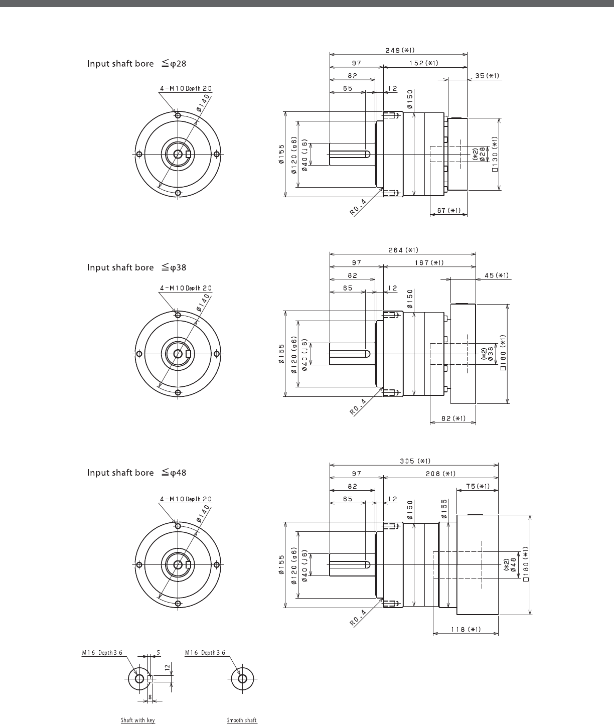
VRL-SERIES Inline shaft
VRL- 1-Stage Dimensions
*1) Length will vary depending on motor
*2) Bushing will be inserted to adapt to motor shaft

VRL
VRL- 2-Stage Dimensions
*1) Length will vary depending on motor
*2) Bushing will be inserted to adapt to motor shaft

VRL-SERIES Inline shaft
VRL- 1-Stage Adapter Dimensions
*1) Single reduction : /~ /
Model number **: Adapter code 1-Stage
L1 L* L2 L3 L4 L5
VRL-155-□-□-19**
(Input shaft bore ≦ φ19)
DA•DB•DC -- -- -- -- -- --
EB•ED -- -- -- -- -- --
FA -- -- -- -- -- --
FB -- -- -- -- -- --
GB•GD•GJ -- -- -- -- -- --
HA -- -- -- -- -- --
HB -- -- -- -- -- --
JA -- -- -- -- -- --
VRL-155-□-□-28**
(Input shaft bore ≦ φ28)
FA•FB•FC 249 214 152 □100 35 67
GA•GB•GC•GD•GE•GF•GG•GH 249 214 152 □115 35 67
HA•HC•HD 249 214 152 □130 35 67
HB 259 214 162 □130 45 77
HF 244 214 147 □130 30 62
JA•JB•JC•JF 249 214 152 □150 35 67
KA•KB•KE 249 214 152 □180 35 67
LA 249 214 152 □200 35 67
LB 259 214 162 □200 45 77
MA 249 214 152 □220 35 67
MB 259 214 162 □220 45 77
VRL-155-□-□-38**
(Input shaft bore ≦ φ38)
HA 264 219 167 □130 45 82
HB•HE 259 219 162 □130 40 77
JA 264 219 167 □150 45 82
KA•KB•KC 264 219 167 □180 45 82
KD 299 219 202 □180 80 117
KE 279 219 182 □180 60 97
LB 274 219 177 □200 55 92
MA•MB 264 219 167 □220 45 82
MC 279 219 182 □220 60 97
MD 274 219 177 □220 55 92
VRL-155-□-□-48**
(Input shaft bore ≦ φ48)
KA 305 230 208 □180 75 118
KB•KC 285 230 188 □180 55 98
LA 285 230 188 □200 55 98
MA 285 230 188 □220 55 98
MB 305 230 208 □220 75 118
A more comprehensive adapter ange o ering can be found using the NIDECSHIMPO Online Selector Tool. The variety is constantly
expanding and being updated on the Selector Tool. If you have any questions or need any support, contact NIDECSHIMPO.
For an explanation on the Adapter Flange Code, please turn to page .
*) Bushing will be inserted to adapt to motor shaft
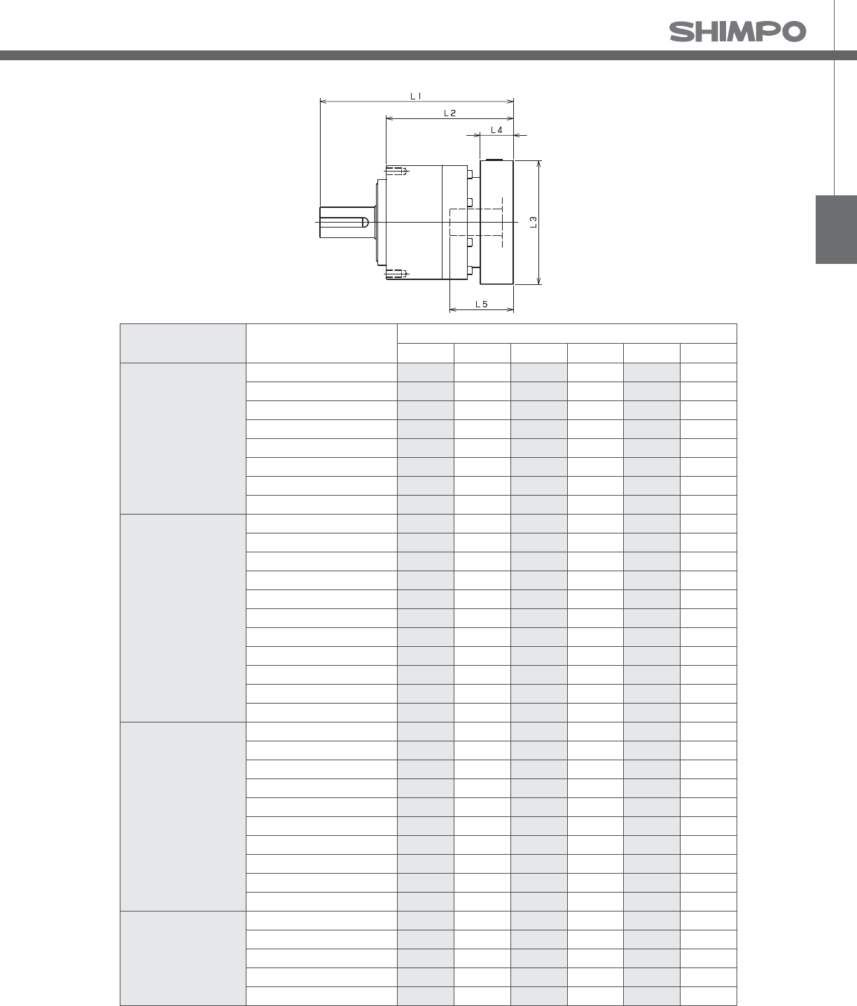
VRL
VRL- 2-Stage Adapter Dimensions
*1) Double reduction : /~ /
Model number **: Adapter code 2-Stage
L1 L* L2 L3 L4 L5
VRL-155-□-□-19**
(Input shaft bore ≦ φ19)
DA•DB•DC 266.5 241.5 169.5 □80 25 50
EB•ED 266.5 241.5 169.5 □90 25 50
FA 266.5 241.5 169.5 □100 25 50
FB 276.5 241.5 179.5 □100 35 60
GB•GD•GJ 266.5 241.5 169.5 □115 25 50
HA 266.5 241.5 169.5 □130 25 50
HB 281.5 241.5 184.5 □130 40 65
JA 276.5 241.5 179.5 □150 35 60
VRL-155-□-□-28**
(Input shaft bore ≦ φ28)
FA•FB•FC 283.5 248.5 186.5 □100 35 67
GA•GB•GC•GD•GE•GF•GG•GH 283.5 248.5 186.5 □115 35 67
HA•HC•HD 283.5 248.5 186.5 □130 35 67
HB 293.5 248.5 196.5 □130 45 77
HF 278.5 248.5 181.5 □130 30 62
JA•JB•JC•JF 283.5 248.5 186.5 □150 35 67
KA•KB•KE 283.5 248.5 186.5 □180 35 67
LA 283.5 248.5 186.5 □200 35 67
LB 293.5 248.5 196.5 □200 45 77
MA 283.5 248.5 186.5 □220 35 67
MB 293.5 248.5 196.5 □220 45 77
VRL-155-□-□-38**
(Input shaft bore ≦ φ38)
HA 298.5 253.5 201.5 □130 45 82
HB•HE 293.5 253.5 196.5 □130 40 77
JA 298.5 253.5 201.5 □150 45 82
KA•KB•KC 298.5 253.5 201.5 □180 45 82
KD 333.5 253.5 236.5 □180 80 117
KE 313.5 253.5 216.5 □180 60 97
LB 308.5 253.5 211.5 □200 55 92
MA•MB 298.5 253.5 201.5 □220 45 82
MC 313.5 253.5 216.5 □220 60 97
MD 308.5 253.5 211.5 □220 55 92
VRL-155-□-□-48**
(Input shaft bore ≦ φ48)
KA 339.5 264.5 242.5 □180 75 118
KB•KC 319.5 264.5 222.5 □180 55 98
LA 319.5 264.5 222.5 □200 55 98
MA 319.5 264.5 222.5 □220 55 98
MB 339.5 264.5 242.5 □220 75 118
A more comprehensive adapter ange o ering can be found using the NIDECSHIMPO Online Selector Tool. The variety is constantly
expanding and being updated on the Selector Tool. If you have any questions or need any support, contact NIDECSHIMPO.
For an explanation on the Adapter Flange Code, please turn to page .
*) Bushing will be inserted to adapt to motor shaft

VRL-SERIES Inline shaft
VRL- 1-Stage Specifications
VRL- 2-Stage Specifications
Frame Size 205
Stage 1-Stage
Ratio Unit Note 3 4 5 6 7 8 9 10
Nominal Output Torque [Nm] *1 500 750 750 750 750 750 500 500
Maximum Acceleration Torque [Nm] *2 970 1400 1400 1400 1400 1400 970 970
Emergency Stop Torque [Nm] *3 2200 2750 2750 2750 2750 2750 2200 2200
Nominal Input Speed [rpm] *4 1500
Maximum Input Speed [rpm] *5 3000
No Load Running Torque [Nm] *6 2.68
Permitted Radial Load [N] *7 5600 6200 6700 7100 7400 7800 8100 8400
Permitted Axial Load [N] *8 4300 4900 5400 5800 6300 6600 7000 7300
Maximum Radial Load [N] *9 15000
Maximum Axial Load [N] *10 14000
Moment of Inertia (≤Ø 28) [kgcm2] -- -- -- -- -- -- -- -- --
Moment of Inertia (≤ Ø 38) [kgcm2] -- 44.000 28.000 22.000 18.000 16.000 15.000 14.000 14.000
Moment of Inertia (≤ Ø 48) [kgcm2] -- 66.000 50.000 44.000 41.000 38.000 37.000 36.000 36.000
Moment of Inertia (≤ Ø 65) [kgcm2] -- 130.000 110.000 100.000 100.000 99.000 97.000 97.000 96.000
E ciency [%] *11 95
Torsional Rigidity [Nm/arc-min] *12 175
Maximum Torsional Backlash [arc-min] -- ≤ 5
Noise Level [dB] *13 67
Protection Class -- *14 IP54 (IP65)
Ambient Temperature [°C] -- 0-40
Permitted Housing Temperature [°C] -- 90
Weight [kg] *15 39
Frame Size 205
Stage 2-Stage
Ratio Unit Note 15 16 20 25 28 30 35 40
Nominal Output Torque [Nm] *1 500 750 750 750 750 500 750 750
Maximum Acceleration Torque [Nm] *2 970 1400 1400 1400 1400 970 1400 1400
Emergency Stop Torque [Nm] *3 2200 2750 2750 2750 2750 2200 2750 2750
Nominal Input Speed [rpm] *4 1500
Maximum Input Speed [rpm] *5 3000
No Load Running Torque [Nm] *6 1.39
Permitted Radial Load [N] *7 9600 9800 11000 11000 12000 12000 13000 13000
Permitted Axial Load [N] *8 8700 8900 9900 11000 11000 12000 13000 13000
Maximum Radial Load [N] *9 15000
Maximum Axial Load [N] *10 14000
Moment of Inertia (≤Ø 28) [kgcm2] -- 4.700 5.400 4.400 4.200 4.900 3.200 4.100 3.200
Moment of Inertia (≤ Ø 38) [kgcm2] -- 12.000 13.000 12.000 12.000 13.000 11.000 12.000 11.000
Moment of Inertia (≤ Ø 48) [kgcm2] -- 34.000 35.000 34.000 34.000 35.000 33.000 34.000 33.000
Moment of Inertia (≤ Ø 65) [kgcm2] -- -- -- -- -- -- -- -- --
E ciency [%] *11 90
Torsional Rigidity [Nm/arc-min] *12 175
Maximum Torsional Backlash [arc-min] -- ≤ 5
Noise Level [dB] *13 67
Protection Class -- *14 IP54 (IP65)
Ambient Temperature [°C] -- 0-40
Permitted Housing Temperature [°C] -- 90
Weight [kg] *15 40

VRL
VRL- 2-Stage Specifications
Frame Size 205
Stage 2-Stage
Ratio Unit Note 45 50 60 70 80 90 100
Nominal Output Torque [Nm] *1 500 750 750 750 750 500 500
Maximum Acceleration Torque [Nm] *2 970 1400 1400 1400 1400 970 970
Emergency Stop Torque [Nm] *3 2200 2750 2750 2750 2750 2200 2200
Nominal Input Speed [rpm] *4 1500
Maximum Input Speed [rpm] *5 3000
No Load Running Torque [Nm] *6 1.39
Permitted Radial Load [N] *7 14000 14000 15000 15000 15000 15000 15000
Permitted Axial Load [N] *8 14000 14000 14000 14000 14000 14000 14000
Maximum Radial Load [N] *9 15000
Maximum Axial Load [N] *10 14000
Moment of Inertia (≤Ø 28) [kgcm2] -- 4.000 3.100 3.100 3.100 3.100 3.100 3.100
Moment of Inertia (≤ Ø 38) [kgcm2] -- 12.000 11.000 11.000 11.000 11.000 11.000 11.000
Moment of Inertia (≤ Ø 48) [kgcm2] -- 34.000 33.000 33.000 33.000 33.000 33.000 33.000
Moment of Inertia (≤ Ø 65) [kgcm2] -- -- -- -- -- -- -- --
E ciency [%] *11 90
Torsional Rigidity [Nm/arc-min] *12 175
Maximum Torsional Backlash [arc-min] -- ≤ 5
Noise Level [dB] *13 67
Protection Class -- *14 IP54 (IP65)
Ambient Temperature [°C] -- 0-40
Permitted Housing Temperature [°C] -- 90
Weight [kg] *15 40
*1) At nominal input speed, service life is , hours
*2) The maximum torque when starting or stopping operation
*3) The maximum torque allowed under a stress situation (Permitted , times during service life)
*4) The average input speed
*5) The maximum intermittent input speed
*6) This is the torque at no load applied on the input shaft. The input speed is , rpm for VRL
*7) At this load and nominal input speed, service life will be , hours. (The radial load applied to the output side bearing)
*8) At this load and nominal input speed, service life will be , hours. (The axial load applied to the output shaft center)
*9) The maximum radial load that the reducer can accept
*10) The maximum axial load that the reducer can accept
*11) The e ciency at the nominal torque rating
*12) This does not include the lost motion
*13) Contact NIDEC-SHIMPO for the testing conditions and environment
*14) IP (wash-down) is available as an option. Contact NIDECSHIMPO for more details and our food grade options
*15) The weight may vary slightly between models

VRL-SERIES Inline shaft
VRL- 1-Stage Dimensions
*1) Length will vary depending on motor
*2) Bushing will be inserted to adapt to motor shaft

VRL
VRL- 2-Stage Dimensions
Input shaft bore䇭㻡φ28
Input shaft bore䇭㻡φ38
Input shaft bore䇭㻡φ48
*1) Length will vary depending on motor
*2) Bushing will be inserted to adapt to motor shaft

VRL-SERIES Inline shaft
VRL- 1-Stage Adapter Dimensions
*1) Single reduction : /~ /
Model number **: Adapter code 1-Stage
L1 L* L2 L3 L4 L5
VRL-205-□-□-28**
(Input shaft bore ≦ φ28)
FA•FB•FC -- -- -- -- -- --
GA•GB•GC•GD•GE•GF•GG•GH -- -- -- -- -- --
HA•HC•HD -- -- -- -- -- --
HB -- -- -- -- -- --
HF -- -- -- -- -- --
JA•JB•JC•JF -- -- -- -- -- --
KA•KB•KE -- -- -- -- -- --
LA -- -- -- -- -- --
LB -- -- -- -- -- --
MA -- -- -- -- -- --
MB -- -- -- -- -- --
VRL-205-□-□-38**
(Input shaft bore ≦ φ38)
HA 286.5 241.5 186.5 □130 45 82
HB•HE 281.5 241.5 181.5 □130 40 77
JA 286.5 241.5 186.5 □150 45 82
KA•KB•KC 286.5 241.5 186.5 □180 45 82
KD 321.5 241.5 221.5 □180 80 117
KE 301.5 241.5 201.5 □180 60 97
LB 296.5 241.5 196.5 □200 55 92
MA•MB 286.5 241.5 186.5 □220 45 82
MC 301.5 241.5 201.5 □220 60 97
MD 296.5 241.5 196.5 □220 55 92
NA 286.5 241.5 186.5 □250 45 82
VRL-205-□-□-48**
(Input shaft bore ≦ φ48)
KA 322.5 247.5 222.5 □180 75 118
KB•KC 302.5 247.5 202.5 □180 55 98
LA 302.5 247.5 202.5 □200 55 98
MA 302.5 247.5 202.5 □220 55 98
MB 322.5 247.5 222.5 □220 75 118
NA 322.5 247.5 222.5 □250 75 118
PA 322.5 247.5 222.5 □280 75 118
VRL-205-□-□-65**
(Input shaft bore ≦ φ65)
MA•MB•MC•MD 334 254 234 □220 80 122
NA•NC 334 254 234 □250 80 122
NB•ND 364 254 264 □250 110 152
PA 354 254 254 □280 100 142
PB 364 254 264 □280 110 152
A more comprehensive adapter ange o ering can be found using the NIDECSHIMPO Online Selector Tool. The variety is constantly
expanding and being updated on the Selector Tool. If you have any questions or need any support, contact NIDECSHIMPO.
For an explanation on the Adapter Flange Code, please turn to page .
*) Bushing will be inserted to adapt to motor shaft

VRL
VRL- 2-Stage Adapter Dimensions
*1) Double reduction : /~ /
Model number **: Adapter code 2-Stage
L1 L* L2 L3 L4 L5
VRL-205-□-□-28**
(Input shaft bore ≦ φ28)
FA•FB•FC 316 281 216 □100 35 67
GA•GB•GC•GD•GE•GF•GG•GH 316 281 216 □115 35 67
HA•HC•HD 316 281 216 □130 35 67
HB 326 281 226 □130 45 77
HF 311 281 211 □130 30 62
JA•JB•JC•JF 316 281 216 □150 35 67
KA•KB•KE 316 281 216 □180 35 67
LA 316 281 216 □200 35 67
LB 326 281 226 □200 45 77
MA 316 281 216 □220 35 67
MB 326 281 226 □220 45 77
VRL-205-□-□-38**
(Input shaft bore ≦ φ38)
HA 331 286 231 □130 45 82
HB•HE 326 286 226 □130 40 77
JA 331 286 231 □150 45 82
KA•KB•KC 331 286 231 □180 45 82
KD 366 286 266 □180 80 117
KE 346 286 246 □180 60 97
LB 341 286 241 □200 55 92
MA•MB 331 286 231 □220 45 82
MC 346 286 246 □220 60 97
MD 341 286 241 □220 55 92
NA 331 286 231 □250 45 82
VRL-205-□-□-48**
(Input shaft bore ≦ φ48)
KA 367 292 267 □180 75 118
KB•KC 347 292 247 □180 55 98
LA 347 292 247 □200 55 98
MA 347 292 247 □220 55 98
MB 367 292 267 □220 75 118
NA 367 292 267 □250 75 118
PA 367 292 267 □280 75 118
VRL-205-□-□-65**
(Input shaft bore ≦ φ65)
MA•MB•MC•MD -- -- -- -- -- --
NA•NC -- -- -- -- -- --
NB•ND -- -- -- -- -- --
PA -- -- -- -- -- --
PB -- -- -- -- -- --
A more comprehensive adapter ange o ering can be found using the NIDECSHIMPO Online Selector Tool. The variety is constantly
expanding and being updated on the Selector Tool. If you have any questions or need any support, contact NIDECSHIMPO.
For an explanation on the Adapter Flange Code, please turn to page .
*) Bushing will be inserted to adapt to motor shaft

VRL-SERIES Inline shaft
VRL- 1-Stage Specifications
VRL- 2-Stage Specifications
Frame Size 235
Stage 1-Stage
Ratio Unit Note 3 4 5 6 7 8 9 10
Nominal Output Torque [Nm] *1 1000 1500 1500 1500 1500 1500 1000 1000
Maximum Acceleration Torque [Nm] *2 1600 2300 2300 2300 2300 2200 1900 1600
Emergency Stop Torque [Nm] *3 4000 5000 5000 5000 5000 5000 4000 4000
Nominal Input Speed [rpm] *4 1000
Maximum Input Speed [rpm] *5 2000
No Load Running Torque [Nm] *6 2.92
Permitted Radial Load [N] *7 5800 6400 6900 7300 7700 8000 8400 8700
Permitted Axial Load [N] *8 6400 7200 7900 8600 9200 9700 10000 11000
Maximum Radial Load [N] *9 15000
Maximum Axial Load [N] *10 14000
Moment of Inertia (≤ Ø 38) [kgcm2] -- -- -- -- -- -- -- -- --
Moment of Inertia (≤ Ø 48) [kgcm2] -- 90.000 62.000 52.000 47.000 42.000 40.000 39.000 38.000
Moment of Inertia (≤ Ø 65) [kgcm2] -- 150.000 120.000 110.000 110.000 100.000 100.000 99.000 98.000
E ciency [%] *11 97
Torsional Rigidity [Nm/arc-min] *12 400
Maximum Torsional Backlash [arc-min] -- ≤ 5
Noise Level [dB] *13 61
Protection Class -- *14 IP54 (IP65)
Ambient Temperature [°C] -- 0-40
Permitted Housing Temperature [°C] -- 90
Weight [kg] *15 55
Frame Size 235
Stage 2-Stage
Ratio Unit Note 15 16 20 25 28 30 35 40
Nominal Output Torque [Nm] *1 1000 1500 1500 1500 1500 1000 1500 1500
Maximum Acceleration Torque [Nm] *2 1600 2300 2300 2300 2300 1600 2300 2300
Emergency Stop Torque [Nm] *3 4000 5000 5000 5000 5000 4000 5000 5000
Nominal Input Speed [rpm] *4 1000
Maximum Input Speed [rpm] *5 2000
No Load Running Torque [Nm] *6 1.14
Permitted Radial Load [N] *7 9900 10000 11000 12000 12000 13000 13000 14000
Permitted Axial Load [N] *8 13000 13000 14000 14000 14000 14000 14000 14000
Maximum Radial Load [N] *9 15000
Maximum Axial Load [N] *10 14000
Moment of Inertia (≤ Ø 38) [kgcm2] -- 14.000 16.000 14.000 14.000 15.000 12.000 13.000 12.000
Moment of Inertia (≤ Ø 48) [kgcm2] -- 36.000 37.000 35.000 35.000 36.000 34.000 35.000 33.000
Moment of Inertia (≤ Ø 65) [kgcm2] -- -- -- -- -- -- -- -- --
E ciency [%] *11 92
Torsional Rigidity [Nm/arc-min] *12 400
Maximum Torsional Backlash [arc-min] -- ≤ 5
Noise Level [dB] *13 61
Protection Class -- *14 IP54 (IP65)
Ambient Temperature [°C] -- 0-40
Permitted Housing Temperature [°C] -- 90
Weight [kg] *15 57

VRL
VRL- 2-Stage Specifications
Frame Size 235
Stage 2-Stage
Ratio Unit Note 45 50 60 70 80 90 100
Nominal Output Torque [Nm] *1 1000 1500 1500 1500 1500 1000 1000
Maximum Acceleration Torque [Nm] *2 1300 2300 2300 2300 1800 1300 1200
Emergency Stop Torque [Nm] *3 4000 5000 5000 5000 5000 4000 4000
Nominal Input Speed [rpm] *4 1000
Maximum Input Speed [rpm] *5 2000
No Load Running Torque [Nm] *6 1.14
Permitted Radial Load [N] *7 14000 15000 15000 15000 15000 15000 15000
Permitted Axial Load [N] *8 14000 14000 14000 14000 14000 14000 14000
Maximum Radial Load [N] *9 15000
Maximum Axial Load [N] *10 14000
Moment of Inertia (≤ Ø 38) [kgcm2] -- 13.000 12.000 12.000 12.000 12.000 12.000 12.000
Moment of Inertia (≤ Ø 48) [kgcm2] -- 35.000 33.000 33.000 33.000 33.000 33.000 33.000
Moment of Inertia (≤ Ø 65) [kgcm2] -- -- -- -- -- -- -- --
E ciency [%] *11 92
Torsional Rigidity [Nm/arc-min] *12 400
Maximum Torsional Backlash [arc-min] -- ≤ 5
Noise Level [dB] *13 61
Protection Class -- *14 IP54 (IP65)
Ambient Temperature [°C] -- 0-40
Permitted Housing Temperature [°C] -- 90
Weight [kg] *15 57
*1) At nominal input speed, service life is , hours
*2) The maximum torque when starting or stopping operation
*3) The maximum torque allowed under a stress situation (Permitted , times during service life)
*4) The average input speed
*5) The maximum intermittent input speed
*6) This is the torque at no load applied on the input shaft. The input speed is , rpm for VRL
*7) At this load and nominal input speed, service life will be , hours. (The radial load applied to the output side bearing)
*8) At this load and nominal input speed, service life will be , hours. (The axial load applied to the output shaft center)
*9) The maximum radial load that the reducer can accept
*10) The maximum axial load that the reducer can accept
*11) The e ciency at the nominal torque rating
*12) This does not include the lost motion
*13) Contact NIDEC-SHIMPO for the testing conditions and environment
*14) IP (wash-down) is available as an option. Contact NIDECSHIMPO for more details and our food grade options
*15) The weight may vary slightly between models
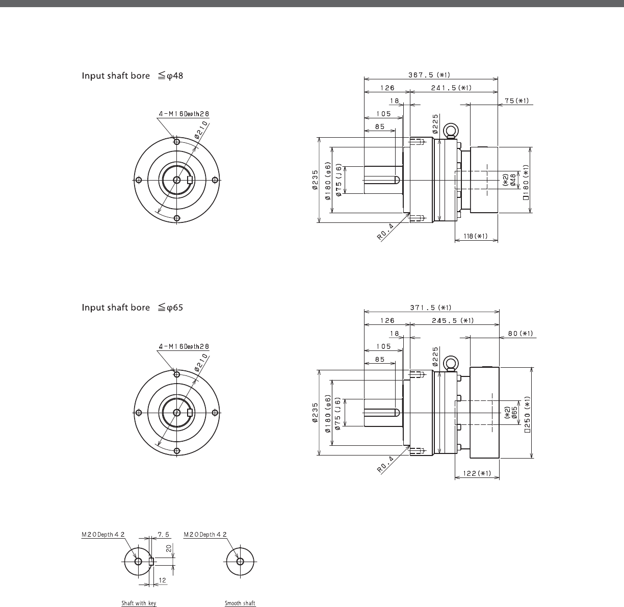
VRL-SERIES Inline shaft
VRL- 1-Stage Dimensions
*1) Length will vary depending on motor
*2) Bushing will be inserted to adapt to motor shaft

VRL
VRL- 2-Stage Dimensions
Input shaft bore䇭㻡φ38
Input shaft bore䇭㻡φ48
*1) Length will vary depending on motor
*2) Bushing will be inserted to adapt to motor shaft

VRL-SERIES Inline shaft
VRL- 1-Stage Adapter Dimensions
*1) Single reduction : /~ /
*2) Bushing will be inserted to adapt to motor shaft
Model number **: Adapter code 1-Stage
L1 L* L2 L3 L4 L5
VRL-235-□-□-38**
(Input shaft bore ≦ φ38)
HA -- -- -- -- -- --
HB•HE -- -- -- -- -- --
JA -- -- -- -- -- --
KA•KB•KC -- -- -- -- -- --
KD -- -- -- -- -- --
KE -- -- -- -- -- --
LA -- -- -- -- -- --
LB -- -- -- -- -- --
MA•MB -- -- -- -- -- --
MC -- -- -- -- -- --
MD -- -- -- -- -- --
NA -- -- -- -- -- --
VRL-235-□-□-48**
(Input shaft bore ≦ φ48)
KA 367.5 292.5 241.5 □180 75 118
KB•KC 347.5 292.5 221.5 □180 55 98
LA 347.5 292.5 221.5 □200 55 98
MA 347.5 292.5 221.5 □220 55 98
MB 367.5 292.5 241.5 □220 75 118
NA 367.5 292.5 241.5 □250 75 118
PA 367.5 292.5 241.5 □280 75 118
VRL-235-□-□-65**
(Input shaft bore ≦ φ65)
MA•MB•MC•MD 371.5 291.5 245.5 □220 80 122
NA•NC 371.5 291.5 245.5 □250 80 122
NB•ND 401.5 291.5 275.5 □250 110 152
PA 391.5 291.5 265.5 □280 100 142
PB 401.5 291.5 275.5 □280 110 152
QA•QB 391.5 291.5 265.5 □320 100 142
A more comprehensive adapter ange o ering can be found using the NIDECSHIMPO Online Selector Tool. The variety is constantly
expanding and being updated on the Selector Tool. If you have any questions or need any support, contact NIDECSHIMPO.
For an explanation on the Adapter Flange Code, please turn to page .

VRL
VRL- 2-Stage Adapter Dimensions
*1) Double reduction : /~ /
*2) Bushing will be inserted to adapt to motor shaft
Model number **: Adapter code 2-Stage
L1 L* L2 L3 L4 L5
VRL-235-□-□-38**
(Input shaft bore ≦ φ38)
HA 366.5 321.5 240.5 □130 45 82
HB•HE 361.5 321.5 235.5 □130 40 77
JA 366.5 321.5 240.5 □150 45 82
KA•KB•KC 366.5 321.5 240.5 □180 45 82
KD 401.5 321.5 275.5 □180 80 117
KE 381.5 321.5 255.5 □180 60 97
LA 366.5 321.5 240.5 □200 45 82
LB 376.5 321.5 250.5 □200 55 92
MA•MB 366.5 321.5 240.5 □220 45 82
MC 381.5 321.5 255.5 □220 60 97
MD 376.5 321.5 250.5 □220 55 92
NA 366.5 321.5 240.5 □250 45 82
VRL-235-□-□-48**
(Input shaft bore ≦ φ48)
KA 402.5 327.5 276.5 □180 75 118
KB•KC 382.5 327.5 256.5 □180 55 98
LA 382.5 327.5 256.5 □200 55 98
MA 382.5 327.5 256.5 □220 55 98
MB 402.5 327.5 276.5 □220 75 118
NA 402.5 327.5 276.5 □250 75 118
PA 402.5 327.5 276.5 □280 75 118
VRL-235-□-□-65**
(Input shaft bore ≦ φ65)
MA•MB•MC•MD -- -- -- -- -- --
NA•NC -- -- -- -- -- --
NB•ND -- -- -- -- -- --
PA -- -- -- -- -- --
PB -- -- -- -- -- --
QA•QB -- -- -- -- -- --
A more comprehensive adapter ange o ering can be found using the NIDECSHIMPO Online Selector Tool. The variety is constantly
expanding and being updated on the Selector Tool. If you have any questions or need any support, contact NIDECSHIMPO.
For an explanation on the Adapter Flange Code, please turn to page .

A
valuable alternative for OEMs that need a high-performance
gearbox, and prefers a flexible mounting design to make it
easier to assemble the gearhead onto their machinery. The posi-
tional accuracy and torque handling capabilities are an ideal fit for
packaging machinery, medical equipment, and custom assembly
cell automation.
The VRB Series planetary gearbox and its standard mounting ange are
a dimensional replacement for a few common competitive models. The
maximum output torque for the series peaks at , Nm. The VRB pro-
vides a backlash rating of < arc-minutes as its standard, which means
this series provides solid performance at an exceptional value.
VRB-SERIES

VRB-SERIES
■Industry standard mounting dimensions
■Large variety of frame sizes and ratios
■Thru-bolt mounting style
■Best-in-class backlash (≤ arc-min)
■Ships in hours in standard frame sizes
■Assembled in the USA
VRB

VRB-SERIES Inline shaft
VRB-Series Features
1 Quiet operation: Helical cut gears contribute to reduced vibration and noise
2 High precision: Standard backlash is arc-min, ideal for higher levels of positional accuracy
3 High rigidity & torque: Rigidity and torque capacity are achieved by using uncaged needle roller bearings
4 Adapter-bushing connection: Enables a simple, e ective attachment to most servo motors
5 No leakage through the seal: High viscosity, anti-separation grease does not liquefy and does not migrate
away from the gears
6 Maintenance-free: No need to replace the grease for the life of the unit. The reducer can be positioned in
any orientation
1
3
6
4
5

VRB
VRB-Series Model Code
Backlash
㩷Adapter ange code
3arc-min3䊶䊶䊶
VR
B 090− − 7 K 3 19HB16−−
Output style 㪪㪿㪸㪽㫋㩷㫎㫀㫋㪿㩷㫂㪼㫐
㪪㫄㫆㫆㫋㪿㩷㫊㪿㪸㪽㫋
㪢䊶䊶䊶
㪪䊶䊶䊶
Ratio Single䋺 3㪃㩷4㪃㩷5㪃㩷6㪃㩷7㪃㩷8㪃㩷9㪃㩷10
Double: 15㪃㩷16㪃㩷20㪃㩷25㪃㩷28㪃㩷30㪃㩷35㪃㩷40, 45㪃㩷50㪃㩷60㪃㩷70㪃㩷80㪃㩷90㪃㩷100
Frame size:䇭㪇㪋㪉㪃㩷㪇㪍㪇㪃㩷㪇㪐㪇㪃㩷㪈㪈㪌㪃㩷㪈㪋㪇㪃㩷㪈㪏㪇㪃㩷㪉㪉㪇
Model name for ABLE reducer
Series name VRB Series
*1) Adapter ange code
Adapter ange code varies depending on the motor
*2) For all washdown intensive and food grade options, refer to pages and
Contact us for additional information or refer to our online reducer selection tool.
Selection tool www.nidec-shimpo.co.jp/selection/eng

VRB-SERIES Inline shaft
Frame Size 042
Stage 1-Stage
Ratio Units Notes 3 4 5 6 7 8 9 10
Nominal Output Torque [Nm] *1 6 9 9 9 9 9 6 6
Maximum Acceleration Torque [Nm] *2 12 18 18 18 18 18 12 12
Emergency Stop Torque [Nm] *3 30 35 35 35 35 35 30 30
Nominal Input Speed [rpm] *4 4000
Maximum Input Speed [rpm] *5 8000
No Load Running Torque [Nm] *6 0.03
Permitted Radial Load [N] *7 240 270 290 310 320 340 350 360
Permitted Axial Load [N] *8 270 300 330 360 380 410 430 450
Maximum Radial Load [N] *9 710
Maximum Axial Load [N] *10 640
Moment of Inertia (≤Ø 8) [kgcm2] -- 0.053 0.041 0.036 0.034 0.032 0.031 0.031 0.030
Moment of Inertia (≤ Ø 14) [kgcm2] -- 0.091 0.079 0.074 0.072 0.071 0.070 0.069 0.069
E ciency [%] *11 95
Torsional Rigidity [Nm/arc-min] *12 2
Maximum Torsional Backlash [arc-min] -- ≤ 3
Noise Level [dB] *13 61
Protection Class -- *14 IP54 (IP65)
Ambient Temperature [°C] -- 0-40
Permitted Housing Temperature [°C] -- 90
Weight [kg] *15 0.6
Frame Size 042
Stage 2-Stage
Ratio Units Notes 15 16 20 25 28 30 35 40
Nominal Output Torque [Nm] *1 6 9 9 9 9 6 9 9
Maximum Acceleration Torque [Nm] *2 12 18 18 18 18 12 18 18
Emergency Stop Torque [Nm] *3 30 35 35 35 35 30 35 35
Nominal Input Speed [rpm] *4 4000
Maximum Input Speed [rpm] *5 8000
No Load Running Torque [Nm] *6 0.01
Permitted Radial Load [N] *7 410 420 460 490 510 520 550 570
Permitted Axial Load [N] *8 540 550 610 640 640 640 640 640
Maximum Radial Load [N] *9 710
Maximum Axial Load [N] *10 640
Moment of Inertia (≤Ø 8) [kgcm2] -- 0.035 0.038 0.034 0.034 0.038 0.030 0.034 0.030
Moment of Inertia (≤ Ø 14) [kgcm2] -- -- -- -- -- -- -- -- --
E ciency [%] *11 90
Torsional Rigidity [Nm/arc-min] *12 2
Maximum Torsional Backlash [arc-min] -- ≤ 5
Noise Level [dB] *13 61
Protection Class -- *14 IP54 (IP65)
Ambient Temperature [°C] -- 0-40
Permitted Housing Temperature [°C] -- 90
Weight [kg] *15 0.7
VRB- 1-Stage Specifications
VRB- 2Stage Specifications

VRB
Frame Size 042
Stage 2-Stage
Ratio Units Notes 45 50 60 70 80 90 100
Nominal Output Torque [Nm] *1 6 9 9 9 9 6 6
Maximum Acceleration Torque [Nm] *2 12 18 18 18 18 12 12
Emergency Stop Torque [Nm] *3 30 35 35 35 35 30 30
Nominal Input Speed [rpm] *4 4000
Maximum Input Speed [rpm] *5 8000
No Load Running Torque [Nm] *6 0.01
Permitted Radial Load [N] *7 600 620 660 690 710 710 710
Permitted Axial Load [N] *8 640 640 640 640 640 640 640
Maximum Radial Load [N] *9 710
Maximum Axial Load [N] *10 640
Moment of Inertia (≤Ø 8) [kgcm2] -- 0.034 0.030 0.030 0.030 0.030 0.030 0.030
Moment of Inertia (≤ Ø 14) [kgcm2] -- -- -- -- -- -- -- --
E ciency [%] *11 90
Torsional Rigidity [Nm/arc-min] *12 2
Maximum Torsional Backlash [arc-min] -- ≤ 5
Noise Level [dB] *13 61
Protection Class -- *14 IP54 (IP65)
Ambient Temperature [°C] -- 0-40
Permitted Housing Temperature [°C] -- 90
Weight [kg] *15 0.7
VRB- 2-Stage Specifications
*1) At nominal input speed, service life is , hours
*2) The maximum torque when starting or stopping operation
*3) The maximum torque allowed under a stress situation (Permitted , times during service life)
*4) The average input speed
*5) The maximum intermittent input speed
*6) This is the torque at no load applied on the input shaft. The input speed is , rpm for VRB
*7) At this load and nominal input speed, service life will be , hours. (The radial load applied to the output side bearing)
*8) At this load and nominal input speed, service life will be , hours. (The axial load applied to the output shaft center)
*9) The maximum radial load that the reducer can accept
*10) The maximum axial load that the reducer can accept
*11) The e ciency at the nominal torque rating
*12) This does not include the lost motion
*13) Contact NIDEC-SHIMPO for the testing conditions and environment
*14) IP (wash-down) is available as an option. Contact NIDECSHIMPO for more details and our food grade options
*15) The weight may vary slightly between models
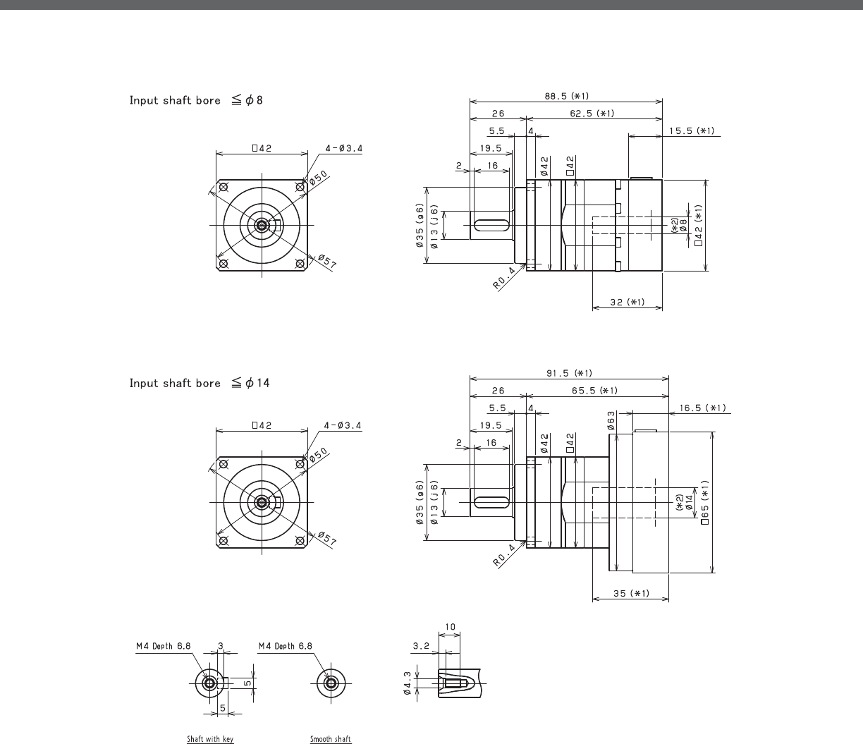
VRB-SERIES Inline shaft
VRB- 1-Stage Dimensions
*1) Length will vary depending on motor
*2) Bushing will be inserted to adapt to motor shaft

VRB
VRB- 2-Stage Dimensions
*1) Length will vary depending on motor
*2) Bushing will be inserted to adapt to motor shaft

VRB-SERIES Inline shaft
VRB- 1-Stage Adapter Dimensions
Model number **: Adapter code 1-Stage
L1 L* L2 L3 L4 L5
VRB-042-□-□-S8**
(Input shaft bore ≦ φ8)
ZA•ZC•ZD•ZF•ZG•ZL•ZM•ZN•ZQ 88.5 73 64 □42 15.5 32
ZB•ZE•ZH•ZJ•ZK 93.5 73 69 □42 20.5 37
BA•BB•BD•BE•BG•BH•BJ 88.5 73 64 □60 15.5 32
BC•BF 93.5 73 69 □60 20.5 37
VRB-042-□-□-14**
(Input shaft bore ≦ φ14)
BA•BB•BD•BE•BF•BG•BJ•BK•BP 91.5 75 67 □65 16.5 35
BC•BH•BM•BN 96.5 75 72 □65 21.5 40
BL 101.5 75 77 □65 26.5 45
*1) Single reduction : /~ /
*2) Bushing will be inserted to adapt to motor shaft
A more comprehensive adapter ange o ering can be found using the NIDECSHIMPO Online Selector Tool. The variety is constantly
expanding and being updated on the Selector Tool. If you have any questions or need any support, contact NIDECSHIMPO.
For an explanation on the Adapter Flange Code, please turn to page .

VRB
VRB- 2-Stage Adapter Dimensions
Model number **: Adapter code 2-Stage
L1 L* L2 L3 L4 L5
VRB-042-□-□-S8**
(Input shaft bore ≦ φ8)
ZA•ZC•ZD•ZF•ZG•ZL•ZM•ZN•ZQ 105 89.5 80.5 □42 15.5 32
ZB•ZE•ZH•ZJ•ZK 110 89.5 85.5 □42 20.5 37
BA•BB•BD•BE•BG•BH•BJ 105 89.5 80.5 □60 15.5 32
BC•BF 110 89.5 85.5 □60 20.5 37
VRB-042-□-□-14**
(Input shaft bore ≦ φ14)
BA•BB•BD•BE•BF•BG•BJ•BK•BP -- -- -- -- -- --
BC•BH•BM•BN -- -- -- -- -- --
BL -- -- -- -- -- --
*1) Double reduction : /~ /
*2) Bushing will be inserted to adapt to motor shaft
A more comprehensive adapter ange o ering can be found using the NIDECSHIMPO Online Selector Tool. The variety is constantly
expanding and being updated on the Selector Tool. If you have any questions or need any support, contact NIDECSHIMPO.
For an explanation on the Adapter Flange Code, please turn to page .

VRB-SERIES Inline shaft
VRB- 1-Stage Specifications
VRB- 2Stage Specifications
Frame Size 060
Stage 1-Stage
Ratio Unit Note 3 4 5 6 7 8 9 10
Nominal Output Torque [Nm] *1 18 27 27 27 27 27 18 18
Maximum Acceleration Torque [Nm] *2 35 50 50 50 50 50 35 35
Emergency Stop Torque [Nm] *3 80 100 100 100 100 100 80 80
Nominal Input Speed [rpm] *4 3000
Maximum Input Speed [rpm] *5 6000
No Load Running Torque [Nm] *6 0.15
Permitted Radial Load [N] *7 430 470 510 540 570 600 620 640
Permitted Axial Load [N] *8 310 360 390 430 460 480 510 530
Maximum Radial Load [N] *9 1200
Maximum Axial Load [N] *10 1100
Moment of Inertia (≤Ø 8) [kgcm2] -- 0.140 0.095 0.077 0.068 0.062 0.059 0.057 0.056
Moment of Inertia (≤ Ø 14) [kgcm2] -- 0.220 0.170 0.160 0.150 0.140 0.140 0.140 0.140
Moment of Inertia (≤ Ø 19) [kgcm2] -- 0.430 0.380 0.360 0.360 0.350 0.350 0.340 0.340
E ciency [%] *11 95
Torsional Rigidity [Nm/arc-min] *12 3
Maximum Torsional Backlash [arc-min] -- ≤ 3
Noise Level [dB] *13 66
Protection Class -- *14 IP54 (IP65)
Ambient Temperature [°C] -- 0-40
Permitted Housing Temperature [°C] -- 90
Weight [kg] *15 1.4
Frame Size 060
Stage 2-Stage
Ratio Unit Note 15 16 20 25 28 30 35 40
Nominal Output Torque [Nm] *1 18 27 27 27 27 18 27 27
Maximum Acceleration Torque [Nm] *2 35 50 50 50 50 35 50 50
Emergency Stop Torque [Nm] *3 80 100 100 100 100 80 100 100
Nominal Input Speed [rpm] *4 3000
Maximum Input Speed [rpm] *5 6000
No Load Running Torque [Nm] *6 0.04
Permitted Radial Load [N] *7 740 750 810 870 910 930 980 1000
Permitted Axial Load [N] *8 630 650 720 790 830 860 920 970
Maximum Radial Load [N] *9 1200
Maximum Axial Load [N] *10 1100
Moment of Inertia (≤Ø 8) [kgcm2] -- 0.055 0.057 0.054 0.053 0.055 0.049 0.053 0.049
Moment of Inertia (≤ Ø 14) [kgcm2] -- 0.140 0.140 0.130 0.130 0.140 0.130 0.130 0.130
Moment of Inertia (≤ Ø 19) [kgcm2] -- -- -- -- -- -- -- -- --
E ciency [%] *11 90
Torsional Rigidity [Nm/arc-min] *12 3
Maximum Torsional Backlash [arc-min] -- ≤ 3
Noise Level [dB] *13 66
Protection Class -- *14 IP54 (IP65)
Ambient Temperature [°C] -- 0-40
Permitted Housing Temperature [°C] -- 90
Weight [kg] *15 1.6

VRB
VRB- 2-Stage Specifications
Frame Size 060
Stage 2-Stage
Ratio Unit Note 45 50 60 70 80 90 100
Nominal Output Torque [Nm] *1 18 27 27 27 27 18 18
Maximum Acceleration Torque [Nm] *2 35 50 50 50 50 35 35
Emergency Stop Torque [Nm] *3 80 100 100 100 100 80 80
Nominal Input Speed [rpm] *4 3000
Maximum Input Speed [rpm] *5 6000
No Load Running Torque [Nm] *6 0.04
Permitted Radial Load [N] *7 1100 1100 1200 1200 1200 1200 1200
Permitted Axial Load [N] *8 1000 1100 1100 1100 1100 1100 1100
Maximum Radial Load [N] *9 1200
Maximum Axial Load [N] *10 1100
Moment of Inertia (≤Ø 8) [kgcm2] -- 0.053 0.049 0.049 0.049 0.049 0.049 0.049
Moment of Inertia (≤ Ø 14) [kgcm2] -- 0.130 0.130 0.130 0.130 0.130 0.130 0.130
Moment of Inertia (≤ Ø 19) [kgcm2] -- -- -- -- -- -- -- --
E ciency [%] *11 90
Torsional Rigidity [Nm/arc-min] *12 3
Maximum Torsional Backlash [arc-min] -- ≤ 3
Noise Level [dB] *13 66
Protection Class -- *14 IP54 (IP65)
Ambient Temperature [°C] -- 0-40
Permitted Housing Temperature [°C] -- 90
Weight [kg] *15 1.6
*1) At nominal input speed, service life is , hours
*2) The maximum torque when starting or stopping operation
*3) The maximum torque allowed under a stress situation (Permitted , times during service life)
*4) The average input speed
*5) The maximum intermittent input speed
*6) This is the torque at no load applied on the input shaft. The input speed is , rpm for VRB
*7) At this load and nominal input speed, service life will be , hours. (The radial load applied to the output side bearing)
*8) At this load and nominal input speed, service life will be , hours. (The axial load applied to the output shaft center)
*9) The maximum radial load that the reducer can accept
*10) The maximum axial load that the reducer can accept
*11) The e ciency at the nominal torque rating
*12) This does not include the lost motion
*13) Contact NIDEC-SHIMPO for the testing conditions and environment
*14) IP (wash-down) is available as an option. Contact NIDECSHIMPO for more details and our food grade options
*15) The weight may vary slightly between models

VRB-SERIES Inline shaft
VRB- 1-Stage Dimensions
*1) Length will vary depending on motor
*2) Bushing will be inserted to adapt to motor shaft

VRB
VRB- 2-Stage Dimensions
*1) Length will vary depending on motor
*2) Bushing will be inserted to adapt to motor shaft

VRB-SERIES Inline shaft
VRB- 1-Stage Adapter Dimensions
*1) Single reduction : /~ /
*2) Bushing will be inserted to adapt to motor shaft
Model number **: Adapter code 1-Stage
L1 L* L2 L3 L4 L5
VRB-060-□-□-8**
(Input shaft bore ≦ φ8)
AA•AC•AD•AF•AG•AL•AM•AN•AQ 112 96.5 75 □52 15.5 32
AB•AE•AH•AJ•AK 117 96.5 80 □52 20.5 37
BA•BB•BD•BE•BG•BH•BJ 112 96.5 75 □60 15.5 32
BC•BF 117 96.5 80 □60 20.5 37
CA 117 96.5 80 □70 20.5 37
VRB-060-□-□-14**
(Input shaft bore ≦ φ14)
BA•BB•BD•BE•BF•BG•BH•BJ•BK•BP 115 98.5 78 □65 16.5 35
BC•BH•BM•BN 120 98.5 83 □65 21.5 40
BL 125 98.5 88 □65 26.5 45
CA•CC 115 98.5 78 □70 16.5 35
CB 120 98.5 83 □70 21.5 40
DA•DB•DC•DD•DF•DH•DJ 115 98.5 78 □80 16.5 35
DE•DL 120 98.5 83 □80 21.5 40
DG•DK 125 98.5 88 □80 26.5 45
EA•EB•EC•EF•EG•EK•EL 115 98.5 78 □90 16.5 35
EJ•EM 120 98.5 83 □90 21.5 40
ED•EE•EH 125 98.5 88 □90 26.5 45
FA 115 98.5 78 □100 16.5 35
FB 125 98.5 88 □100 26.5 45
VRB-060-□-□-19**
(Input shaft bore ≦ φ19)
DA•DB•DC 130 105 93 □80 25 50
DD 140 105 103 □80 35 60
DE 135 105 98 □80 30 55
EA 135 105 98 □90 30 55
EB•ED 130 105 93 □90 25 50
EC 140 105 103 □90 35 60
FA 130 105 93 □100 25 50
FB 140 105 103 □100 35 60
A more comprehensive adapter ange o ering can be found using the NIDECSHIMPO Online Selector Tool. The variety is constantly
expanding and being updated on the Selector Tool. If you have any questions or need any support, contact NIDECSHIMPO.
For an explanation on the Adapter Flange Code, please turn to page .

VRB
VRB- 2-Stage Adapter Dimensions
*1) Double reduction : /~ /
*2) Bushing will be inserted to adapt to motor shaft
Model number **: Adapter code 2-Stage
L1 L* L2 L3 L4 L5
VRB-060-□-□-8**
(Input shaft bore ≦ φ8)
AA•AC•AD•AF•AG•AL•AM•AN•AQ 131 115.5 94 □52 15.5 32
AB•AE•AH•AJ•AK 136 115.5 99 □52 20.5 37
BA•BB•BD•BE•BG•BH•BJ 131 115.5 94 □60 15.5 32
BC•BF 136 115.5 99 □60 20.5 37
CA 136 115.5 99 □70 20.5 37
VRB-060-□-□-14**
(Input shaft bore ≦ φ14)
BA•BB•BD•BE•BF•BG•BH•BJ•BK•BP 136 119.5 99 □65 16.5 35
BC•BH•BM•BN 141 119.5 104 □65 21.5 40
BL 146 119.5 109 □65 26.5 45
CA•CC 136 119.5 99 □70 16.5 35
CB 141 119.5 104 □70 21.5 40
DA•DB•DC•DD•DF•DH•DJ 136 119.5 99 □80 16.5 35
DE•DL 141 119.5 104 □80 21.5 40
DG•DK 146 119.5 109 □80 26.5 45
EA•EB•EC•EF•EG•EK•EL 136 119.5 99 □90 16.5 35
EJ•EM 141 119.5 104 □90 21.5 40
ED•EE•EH 146 119.5 109 □90 26.5 45
FA 136 119.5 99 □100 16.5 35
FB 146 119.5 109 □100 26.5 45
VRB-060-□-□-19**
(Input shaft bore ≦ φ19)
DA•DB•DC 151 126 114 □80 25 50
DD 161 126 124 □80 35 60
DE 156 126 119 □80 30 55
EA 156 126 119 □90 30 55
EB•ED 151 126 114 □90 25 50
EC 161 126 124 □90 35 60
FA 151 126 114 □100 25 50
FB 161 126 124 □100 35 60
A more comprehensive adapter ange o ering can be found using the NIDECSHIMPO Online Selector Tool. The variety is constantly
expanding and being updated on the Selector Tool. If you have any questions or need any support, contact NIDECSHIMPO.
For an explanation on the Adapter Flange Code, please turn to page .

VRB-SERIES Inline shaft
VRB- 1-Stage Specifications
VRB- 2-Stage Specifications
Frame Size 090
Stage 1-Stage
Ratio Unit Note 3 4 5 6 7 8 9 10
Nominal Output Torque [Nm] *1 50 75 75 75 75 75 50 50
Maximum Acceleration Torque [Nm] *2 80 125 125 125 125 125 80 80
Emergency Stop Torque [Nm] *3 200 250 250 250 250 250 200 200
Nominal Input Speed [rpm] *4 3000
Maximum Input Speed [rpm] *5 6000
No Load Running Torque [Nm] *6 0.35
Permitted Radial Load [N] *7 810 890 960 1000 1100 1100 1200 1200
Permitted Axial Load [N] *8 930 1100 1200 1300 1300 1400 1500 1600
Maximum Radial Load [N] *9 2400
Maximum Axial Load [N] *10 2200
Moment of Inertia (≤Ø 8) [kgcm2] -- -- -- -- -- -- -- -- --
Moment of Inertia (≤ Ø 14) [kgcm2] -- 0.720 0.490 0.400 0.360 0.320 0.310 0.290 0.290
Moment of Inertia (≤ Ø 19) [kgcm2] -- 1.200 0.950 0.860 0.820 0.790 0.770 0.760 0.750
Moment of Inertia (≤ Ø 28) [kgcm2] -- 3.200 3.000 2.900 2.800 2.800 2.800 2.800 2.800
E ciency [%] *11 95
Torsional Rigidity [Nm/arc-min] *12 10
Maximum Torsional Backlash [arc-min] -- ≤ 3
Noise Level [dB] *13 67
Protection Class -- *14 IP54 (IP65)
Ambient Temperature [°C] -- 0-40
Permitted Housing Temperature [°C] -- 90
Weight [kg] *15 3.7
Frame Size 090
Stage 2-Stage
Ratio Unit Note 15 16 20 25 28 30 35 40
Nominal Output Torque [Nm] *1 50 75 75 75 75 50 75 75
Maximum Acceleration Torque [Nm] *2 80 125 125 125 125 80 125 125
Emergency Stop Torque [Nm] *3 200 250 250 250 250 200 250 250
Nominal Input Speed [rpm] *4 3000
Maximum Input Speed [rpm] *5 6000
No Load Running Torque [Nm] *6 0.06
Permitted Radial Load [N] *7 1400 1400 1500 1600 1700 1700 1800 1900
Permitted Axial Load [N] *8 1900 1900 2100 2200 2200 2200 2200 2200
Maximum Radial Load [N] *9 2400
Maximum Axial Load [N] *10 2200
Moment of Inertia (≤Ø 8) [kgcm2] -- 0.130 0.150 0.130 0.120 0.140 0.100 0.120 0.099
Moment of Inertia (≤ Ø 14) [kgcm2] -- 0.280 0.300 0.280 0.280 0.290 0.250 0.270 0.250
Moment of Inertia (≤ Ø 19) [kgcm2] -- 0.720 0.740 0.720 0.710 0.730 0.700 0.710 0.700
Moment of Inertia (≤ Ø 28) [kgcm2] -- -- -- -- -- -- -- -- --
E ciency [%] *11 90
Torsional Rigidity [Nm/arc-min] *12 10
Maximum Torsional Backlash [arc-min] -- ≤ 3
Noise Level [dB] *13 67
Protection Class -- *14 IP54 (IP65)
Ambient Temperature [°C] -- 0-40
Permitted Housing Temperature [°C] -- 90
Weight [kg] *15 4.2

VRB
VRB- 2-Stage Specifications
Frame Size 090
Stage 2-Stage
Ratio Unit Note 45 50 60 70 80 90 100
Nominal Output Torque [Nm] *1 50 75 75 75 75 50 50
Maximum Acceleration Torque [Nm] *2 80 125 125 125 125 80 80
Emergency Stop Torque [Nm] *3 200 250 250 250 250 200 200
Nominal Input Speed [rpm] *4 3000
Maximum Input Speed [rpm] *5 6000
No Load Running Torque [Nm] *6 0.06
Permitted Radial Load [N] *7 2000 2100 2200 2300 2400 2400 2400
Permitted Axial Load [N] *8 2200 2200 2200 2200 2200 2200 2200
Maximum Radial Load [N] *9 2400
Maximum Axial Load [N] *10 2200
Moment of Inertia (≤Ø 8) [kgcm2] -- 0.120 0.098 0.098 0.097 0.097 0.097 0.097
Moment of Inertia (≤ Ø 14) [kgcm2] -- 0.270 0.250 0.250 0.250 0.250 0.250 0.250
Moment of Inertia (≤ Ø 19) [kgcm2] -- 0.710 0.690 0.690 0.690 0.690 0.690 0.690
Moment of Inertia (≤ Ø 28) [kgcm2] -- -- -- -- -- -- -- --
E ciency [%] *11 90
Torsional Rigidity [Nm/arc-min] *12 10
Maximum Torsional Backlash [arc-min] -- ≤ 3
Noise Level [dB] *13 67
Protection Class -- *14 IP54 (IP65)
Ambient Temperature [°C] -- 0-40
Permitted Housing Temperature [°C] -- 90
Weight [kg] *15 4.2
*1) At nominal input speed, service life is , hours
*2) The maximum torque when starting or stopping operation
*3) The maximum torque allowed under a stress situation (Permitted , times during service life)
*4) The average input speed
*5) The maximum intermittent input speed
*6) This is the torque at no load applied on the input shaft. The input speed is , rpm for VRB
*7) At this load and nominal input speed, service life will be , hours. (The radial load applied to the output side bearing)
*8) At this load and nominal input speed, service life will be , hours. (The axial load applied to the output shaft center)
*9) The maximum radial load that the reducer can accept
*10) The maximum axial load that the reducer can accept
*11) The e ciency at the nominal torque rating
*12) This does not include the lost motion
*13) Contact NIDEC-SHIMPO for the testing conditions and environment
*14) IP (wash-down) is available as an option. Contact NIDECSHIMPO for more details and our food grade options
*15) The weight may vary slightly between models

VRB-SERIES Inline shaft
VRB- 1-Stage Dimensions
*1) Length will vary depending on motor
*2) Bushing will be inserted to adapt to motor shaft

VRB
VRB- 2-Stage Dimensions
*1) Length will vary depending on motor
*2) Bushing will be inserted to adapt to motor shaft

VRB-SERIES Inline shaft
VRB- 1-Stage Adapter Dimensions
*1) Single reduction : /~ /
Model number **: Adapter code 1-Stage
L1 L* L2 L3 L4 L5
VRB-090-□-□-8**
(Input shaft bore ≦ φ8)
AA•AC•AD•AF•AG•AL•AM•AN•AQ -- -- -- -- -- --
AB•AE•AH•AJ•AK -- -- -- -- -- --
BA•BB•BD•BE•BG•BH•BJ -- -- -- -- -- --
CA -- -- -- -- -- --
VRB-090-□-□-14**
(Input shaft bore ≦ φ14)
BA•BB•BD•BE•BF•BG•BH•BJ•BK•BP 143 126.5 95 □65 16.5 35
BC•BH•BM•BN 148 126.5 100 □65 21.5 40
CA•CC 143 126.5 95 □70 16.5 35
DA•DB•DC•DD•DF•DH•DJ 143 126.5 95 □80 16.5 35
EA•EB•EC•EF•EG•EK•EL 143 126.5 95 □90 16.5 35
FA 143 126.5 95 □100 16.5 35
FB 153 126.5 105 □100 26.5 45
JA 158 126.5 110 □150 31.5 50
VRB-090-□-□-19**
(Input shaft bore ≦ φ19)
DA•DB•DC 153 128 105 □80 25 50
EB•ED 153 128 105 □90 25 50
FA 153 128 105 □100 25 50
FB 163 128 115 □100 35 60
GA•GC•GH 158 128 110 □115 30 55
GB•GD•GJ 153 128 105 □115 25 50
GE•GF 163 128 115 □115 35 60
HA 153 128 105 □130 25 50
HB 168 128 120 □130 40 65
HC•HD•HE 158 128 110 □130 30 55
JA 163 128 115 □150 35 60
JB 168 128 120 □150 40 65
VRB-090-□-□-28**
(Input shaft bore ≦ φ28)
FA•FB•FC 170 135 122 □100 35 67
FD•FE 165 135 117 □100 30 62
GA•GB•GC•GD•GE•GF•GG•GH 170 135 122 □115 35 67
HA•HC•HD 170 135 122 □130 35 67
HB 180 135 132 □130 45 77
HE 185 135 137 □130 50 82
HF 165 135 117 □130 30 62
JA•JB•JC•JF 170 135 122 □150 35 67
JD 190 135 142 □150 55 87
JE 180 135 132 □150 45 77
A more comprehensive adapter ange o ering can be found using the NIDECSHIMPO Online Selector Tool. The variety is constantly
expanding and being updated on the Selector Tool. If you have any questions or need any support, contact NIDECSHIMPO.
For an explanation on the Adapter Flange Code, please turn to page .
*) Bushing will be inserted to adapt to motor shaft

VRB
VRB- 2-Stage Adapter Dimensions
*1) Double reduction : /~ /
Model number **: Adapter code 2-Stage
L1 L* L2 L3 L4 L5
VRB-090-□-□-8**
(Input shaft bore ≦ φ8)
AA•AC•AD•AF•AG•AL•AM•AN•AQ 160 144.5 112 □52 15.5 32
AB•AE•AH•AJ•AK 165 144.5 117 □52 20.5 37
BA•BB•BD•BE•BG•BH•BJ 160 144.5 112 □60 15.5 32
CA 165 144.5 117 □70 20.5 37
VRB-090-□-□-14**
(Input shaft bore ≦ φ14)
BA•BB•BD•BE•BF•BG•BH•BJ•BK•BP 165 148.5 117 □65 16.5 35
BC•BH•BM•BN 170 148.5 122 □65 21.5 40
CA•CC 165 148.5 117 □70 16.5 35
DA•DB•DC•DD•DF•DH•DJ 165 148.5 117 □80 16.5 35
EA•EB•EC•EF•EG•EK•EL 165 148.5 117 □90 16.5 35
FA 165 148.5 117 □100 16.5 35
FB 175 148.5 127 □100 26.5 45
JA 180 148.5 132 □150 31.5 50
VRB-090-□-□-19**
(Input shaft bore ≦ φ19)
DA•DB•DC 175 150 127 □80 25 50
EB•ED 175 150 127 □90 25 50
FA 175 150 127 □100 25 50
FB 185 150 137 □100 35 60
GA•GC•GH 180 150 132 □115 30 55
GB•GD•GJ 175 150 127 □115 25 50
GE•GF 185 150 137 □115 35 60
HA 175 150 127 □130 25 50
HB 190 150 142 □130 40 65
HC•HD•HE 180 150 132 □130 30 55
JA 185 150 137 □150 35 60
JB 190 150 142 □150 40 65
VRB-090-□-□-28**
(Input shaft bore ≦ φ28)
FA•FB•FC 194 159 146 □100 35 67
FD•FE 189 159 141 □100 30 62
GA•GB•GC•GD•GE•GF•GG•GH 194 159 146 □115 35 67
HA•HC•HD 194 159 146 □130 35 67
HB 204 159 156 □130 45 77
HE 209 159 161 □130 50 82
HF 189 159 141 □130 30 62
JA•JB•JC•JF 194 159 146 □150 35 67
JD 214 159 166 □150 55 87
JE 204 159 156 □150 45 77
A more comprehensive adapter ange o ering can be found using the NIDECSHIMPO Online Selector Tool. The variety is constantly
expanding and being updated on the Selector Tool. If you have any questions or need any support, contact NIDECSHIMPO.
For an explanation on the Adapter Flange Code, please turn to page .
*) Bushing will be inserted to adapt to motor shaft

VRB-SERIES Inline shaft
VRB- 1-Stage Specifications
VRB- 2-Stage Specifications
Frame Size 115
Stage 1-Stage
Ratio Unit Note 3 4 5 6 7 8 9 10
Nominal Output Torque [Nm] *1 120 120 180 180 180 180 120 120
Maximum Acceleration Torque [Nm] *2 225 330 330 330 330 330 225 225
Emergency Stop Torque [Nm] *3 500 625 625 625 625 625 500 500
Nominal Input Speed [rpm] *4 3000
Maximum Input Speed [rpm] *5 6000
No Load Running Torque [Nm] *6 1.30
Permitted Radial Load [N] *7 1300 1500 1600 1700 1800 1900 1900 2000
Permitted Axial Load [N] *8 1500 1700 1900 2000 2100 2300 2400 2500
Maximum Radial Load [N] *9 4300
Maximum Axial Load [N] *10 3900
Moment of Inertia (≤Ø 14) [kgcm2] -- -- -- -- -- -- -- -- --
Moment of Inertia (≤ Ø 19) [kgcm2] -- 3.300 2.000 1.600 1.300 1.100 1.000 0.980 0.950
Moment of Inertia (≤ Ø 28) [kgcm2] -- 5.300 4.100 3.600 3.300 3.200 3.100 3.000 3.000
Moment of Inertia (≤ Ø 38) [kgcm2] -- 13.000 12.000 11.000 11.000 11.000 11.000 11.000 11.000
E ciency [%] *11 95
Torsional Rigidity [Nm/arc-min] *12 31
Maximum Torsional Backlash [arc-min] -- ≤ 3
Noise Level [dB] *13 71
Protection Class -- *14 IP54 (IP65)
Ambient Temperature [°C] -- 0-40
Permitted Housing Temperature [°C] -- 90
Weight [kg] *15 8
Frame Size 115
Stage 2-Stage
Ratio Unit Note 15 16 20 25 28 30 35 40
Nominal Output Torque [Nm] *1 120 180 180 180 180 120 180 180
Maximum Acceleration Torque [Nm] *2 225 330 330 330 330 225 330 330
Emergency Stop Torque [Nm] *3 500 625 625 625 625 500 625 625
Nominal Input Speed [rpm] *4 3000
Maximum Input Speed [rpm] *5 6000
No Load Running Torque [Nm] *6 0.42
Permitted Radial Load [N] *7 2300 2300 2500 2700 2800 2900 3000 3200
Permitted Axial Load [N] *8 3000 3100 3400 3700 3900 3900 3900 3900
Maximum Radial Load [N] *9 4300
Maximum Axial Load [N] *10 3900
Moment of Inertia (≤Ø 14) [kgcm2] -- 0.430 0.480 0.400 0.380 0.440 0.290 0.370 0.280
Moment of Inertia (≤ Ø 19) [kgcm2] -- 0.860 0.920 0.830 0.820 0.880 0.740 0.810 0.730
Moment of Inertia (≤ Ø 28) [kgcm2] -- 2.800 2.900 2.800 2.800 2.800 2.700 2.700 2.700
Moment of Inertia (≤ Ø 38) [kgcm2] -- -- -- -- -- -- -- -- --
E ciency [%] *11 90
Torsional Rigidity [Nm/arc-min] *12 31
Maximum Torsional Backlash [arc-min] -- ≤ 3
Noise Level [dB] *13 71
Protection Class -- *14 IP54 (IP65)
Ambient Temperature [°C] -- 0-40
Permitted Housing Temperature [°C] -- 90
Weight [kg] *15 8.9

VRB
VRB- 2-Stage Specifications
Frame Size 115
Stage 2-Stage
Ratio Unit Note 45 50 60 70 80 90 100
Nominal Output Torque [Nm] *1 120 180 180 180 180 120 120
Maximum Acceleration Torque [Nm] *2 225 330 330 330 330 225 225
Emergency Stop Torque [Nm] *3 500 625 625 625 625 500 500
Nominal Input Speed [rpm] *4 3000
Maximum Input Speed [rpm] *5 6000
No Load Running Torque [Nm] *6 0.42
Permitted Radial Load [N] *7 3300 3400 3600 3800 4000 4200 4300
Permitted Axial Load [N] *8 3900 3900 3900 3900 3900 3900 3900
Maximum Radial Load [N] *9 4300
Maximum Axial Load [N] *10 3900
Moment of Inertia (≤Ø 14) [kgcm2] -- 0.370 0.280 0.280 0.280 0.280 0.270 0.270
Moment of Inertia (≤ Ø 19) [kgcm2] -- 0.800 0.730 0.730 0.730 0.730 0.730 0.730
Moment of Inertia (≤ Ø 28) [kgcm2] -- 2.700 2.700 2.700 2.700 2.700 2.700 2.700
Moment of Inertia (≤ Ø 38) [kgcm2] -- -- -- -- -- -- -- --
E ciency [%] *11 90
Torsional Rigidity [Nm/arc-min] *12 31
Maximum Torsional Backlash [arc-min] -- ≤ 3
Noise Level [dB] *13 71
Protection Class -- *14 IP54 (IP65)
Ambient Temperature [°C] -- 0-40
Permitted Housing Temperature [°C] -- 90
Weight [kg] *15 8.9
*1) At nominal input speed, service life is , hours
*2) The maximum torque when starting or stopping operation
*3) The maximum torque allowed under a stress situation (Permitted , times during service life)
*4) The average input speed
*5) The maximum intermittent input speed
*6) This is the torque at no load applied on the input shaft. The input speed is , rpm for VRB
*7) At this load and nominal input speed, service life will be , hours. (The radial load applied to the output side bearing)
*8) At this load and nominal input speed, service life will be , hours. (The axial load applied to the output shaft center)
*9) The maximum radial load that the reducer can accept
*10) The maximum axial load that the reducer can accept
*11) The e ciency at the nominal torque rating
*12) This does not include the lost motion
*13) Contact NIDEC-SHIMPO for the testing conditions and environment
*14) IP (wash-down) is available as an option. Contact NIDECSHIMPO for more details and our food grade options
*15) The weight may vary slightly between models

VRB-SERIES Inline shaft
VRB- 1-Stage Dimensions
*1) Length will vary depending on motor
*2) Bushing will be inserted to adapt to motor shaft
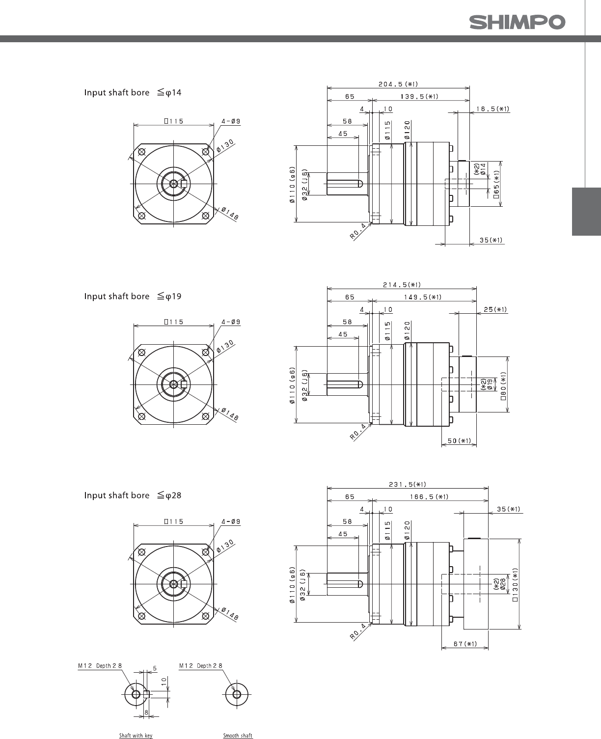
VRB
VRB- 2-Stage Dimensions
*1) Length will vary depending on motor
*2) Bushing will be inserted to adapt to motor shaft

VRB-SERIES Inline shaft
VRB- 1-Stage Adapter Dimensions
*1) Single reduction : /~ /
Model number **: Adapter code 1-Stage
L1 L* L2 L3 L4 L5
VRB-115-□-□-14**
(Input shaft bore ≦ φ14)
BA•BB•BD•BE•BF•BG•BH•BJ•BK•BP -- -- -- -- -- --
BC•BH•BM•BN -- -- -- -- -- --
CA•CC ------------
DA•DB•DC•DD•DF•DH•DJ -- -- -- -- -- --
EA•EB•EC•EF•EG•EK•EL -- -- -- -- -- --
FA -- -- -- -- -- --
FB -- -- -- -- -- --
JA -- -- -- -- -- --
VRB-115-□-□-19**
(Input shaft bore ≦ φ19)
DA•DB•DC 187 162 122 □80 25 50
EB•ED 187 162 122 □90 25 50
FA 187 162 122 □100 25 50
FB 197 162 132 □100 35 60
GB•GD•GJ 187 162 122 □115 25 50
HA 187 162 122 □130 25 50
HB 202 162 137 □130 40 65
JA 197 162 132 □150 35 60
VRB-115-□-□-28**
(Input shaft bore ≦ φ28)
FA•FB•FC 204 169 139 □100 35 67
FD•FE 199 169 134 □100 30 62
GA•GB•GC•GD•GE•GF•GG•GH 204 169 139 □115 35 67
HA•HC•HD 204 169 139 □130 35 67
HB 214 169 149 □130 45 77
HE 219 169 154 □130 50 82
HF 199 169 134 □130 30 62
JA•JB•JC•JF 204 169 139 □150 35 67
JD 224 169 159 □150 55 87
JE 214 169 149 □150 45 77
KA•KB•KE 204 169 139 □180 35 67
KD 214 169 149 □180 45 77
VRB-115-□-□-38**
(Input shaft bore ≦ φ38)
HA 225 180 160 □130 45 82
HB•HE 220 180 155 □130 40 77
JA 225 180 160 □150 45 82
KA•KB•KC 225 180 160 □180 45 82
KD 260 180 195 □180 80 117
KE 240 180 175 □180 60 97
A more comprehensive adapter ange o ering can be found using the NIDECSHIMPO Online Selector Tool. The variety is constantly
expanding and being updated on the Selector Tool. If you have any questions or need any support, contact NIDECSHIMPO.
For an explanation on the Adapter Flange Code, please turn to page .
*) Bushing will be inserted to adapt to motor shaft

VRB
VRB- 2-Stage Adapter Dimensions
*1) Double reduction : /~ /
Model number **: Adapter code 2-Stage
L1 L* L2 L3 L4 L5
VRB-115-□-□-14**
(Input shaft bore ≦ φ14)
BA•BB•BD•BE•BF•BG•BH•BJ•BK•BP 204.5 188 139.5 □65 16.5 35
BC•BH•BM•BN 209.5 188 144.5 □65 21.5 40
CA•CC 204.5 188 139.5 □70 16.5 35
DA•DB•DC•DD•DF•DH•DJ 204.5 188 139.5 □80 16.5 35
EA•EB•EC•EF•EG•EK•EL 204.5 188 139.5 □90 16.5 35
FA 204.5 188 139.5 □100 16.5 35
FB 214.5 188 149.5 □100 26.5 45
JA 219.5 188 154.5 □150 31.5 50
VRB-115-□-□-19**
(Input shaft bore ≦ φ19)
DA•DB•DC 214.5 189.5 149.5 □80 25 50
EB•ED 214.5 189.5 149.5 □90 25 50
FA 214.5 189.5 149.5 □100 25 50
FB 224.5 189.5 159.5 □100 35 60
GB•GD•GJ 214.5 189.5 149.5 □115 25 50
HA 214.5 189.5 149.5 □130 25 50
HB 229.5 189.5 164.5 □130 40 65
JA 224.5 189.5 159.5 □150 35 60
VRB-115-□-□-28**
(Input shaft bore ≦ φ28)
FA•FB•FC 231.5 196.5 166.5 □100 35 67
FD•FE 226.5 196.5 161.5 □100 30 62
GA•GB•GC•GD•GE•GF•GG•GH 231.5 196.5 166.5 □115 35 67
HA•HC•HD 231.5 196.5 166.5 □130 35 67
HB 241.5 196.5 176.5 □130 45 77
HE 246.5 196.5 181.5 □130 50 82
HF 226.5 196.5 161.5 □130 30 62
JA•JB•JC•JF 231.5 196.5 166.5 □150 35 67
JD 251.5 196.5 186.5 □150 55 87
JE 241.5 196.5 176.5 □150 45 77
KA•KB•KE 231.5 196.5 166.5 □180 35 67
KD 241.5 196.5 176.5 □180 45 77
VRB-115-□-□-38**
(Input shaft bore ≦ φ38)
HA 249 204 184 □130 45 82
HB•HE 244 204 179 □130 40 77
JA 249 204 184 □150 45 82
KA•KB•KC 249 204 184 □180 45 82
KD 284 204 219 □180 80 117
KE 264 204 199 □180 60 97
A more comprehensive adapter ange o ering can be found using the NIDECSHIMPO Online Selector Tool. The variety is constantly
expanding and being updated on the Selector Tool. If you have any questions or need any support, contact NIDECSHIMPO.
For an explanation on the Adapter Flange Code, please turn to page .
*) Bushing will be inserted to adapt to motor shaft

VRB-SERIES Inline shaft
VRB- 1-Stage Specifications
VRB- 2-Stage Specifications
Frame Size 140
Stage 1-Stage
Ratio Unit Note 3 4 5 6 7 8 9 10
Nominal Output Torque [Nm] *1 240 240 360 360 360 360 240 240
Maximum Acceleration Torque [Nm] *2 470 700 700 700 700 700 470 470
Emergency Stop Torque [Nm] *3 1000 1250 1250 1250 1250 1250 1000 1000
Nominal Input Speed [rpm] *4 2000
Maximum Input Speed [rpm] *5 4000
No Load Running Torque [Nm] *6 1.63
Permitted Radial Load [N] *7 3200 3500 3800 4000 4200 4400 4600 4700
Permitted Axial Load [N] *8 2400 2700 3000 3300 3500 3700 3900 4100
Maximum Radial Load [N] *9 9100
Maximum Axial Load [N] *10 8200
Moment of Inertia (≤Ø 19) [kgcm2] -- -- -- -- -- -- -- -- --
Moment of Inertia (≤ Ø 28) [kgcm2] -- 12.000 7.500 5.800 4.900 4.100 3.800 3.600 3.500
Moment of Inertia (≤ Ø 38) [kgcm2] -- 20.000 15.000 14.000 13.000 12.000 12.000 11.000 11.000
Moment of Inertia (≤ Ø 48) [kgcm2] -- 42.000 37.000 36.000 35.000 34.000 34.000 34.000 34.000
E ciency [%] *11 95
Torsional Rigidity [Nm/arc-min] *12 60
Maximum Torsional Backlash [arc-min] -- ≤ 3
Noise Level [dB] *13 67
Protection Class -- *14 IP54 (IP65)
Ambient Temperature [°C] -- 0-40
Permitted Housing Temperature [°C] -- 90
Weight [kg] *15 16
Frame Size 140
Stage 2-Stage
Ratio Unit Note 15 16 20 25 28 30 35 40
Nominal Output Torque [Nm] *1 240 360 360 360 360 240 360 360
Maximum Acceleration Torque [Nm] *2 470 700 700 700 700 470 700 700
Emergency Stop Torque [Nm] *3 1000 1250 1250 1250 1250 1000 1250 1250
Nominal Input Speed [rpm] *4 2000
Maximum Input Speed [rpm] *5 4000
No Load Running Torque [Nm] *6 0.56
Permitted Radial Load [N] *7 5400 5500 6000 6400 6700 6800 7200 7500
Permitted Axial Load [N] *8 4900 5000 5500 6100 6400 6600 7000 7500
Maximum Radial Load [N] *9 9100
Maximum Axial Load [N] *10 8200
Moment of Inertia (≤Ø 19) [kgcm2] -- 1.300 1.500 1.200 1.100 1.400 0.850 1.100 0.830
Moment of Inertia (≤ Ø 28) [kgcm2] -- 3.200 3.500 3.100 3.100 3.300 2.800 3.100 2.800
Moment of Inertia (≤ Ø 38) [kgcm2] -- 11.000 11.000 11.000 11.000 11.000 10.000 11.000 10.000
Moment of Inertia (≤ Ø 48) [kgcm2] -- -- -- -- -- -- -- -- --
E ciency [%] *11 90
Torsional Rigidity [Nm/arc-min] *12 60
Maximum Torsional Backlash [arc-min] -- ≤ 3
Noise Level [dB] *13 67
Protection Class -- *14 IP54 (IP65)
Ambient Temperature [°C] -- 0-40
Permitted Housing Temperature [°C] -- 90
Weight [kg] *15 17

VRB
VRB- 2-Stage Specifications
Frame Size 140
Stage 2-Stage
Ratio Unit Note 45 50 60 70 80 90 100
Nominal Output Torque [Nm] *1 240 360 360 360 360 240 240
Maximum Acceleration Torque [Nm] *2 470 700 700 700 700 470 470
Emergency Stop Torque [Nm] *3 1000 1250 1250 1250 1250 1000 1000
Nominal Input Speed [rpm] *4 2000
Maximum Input Speed [rpm] *5 4000
No Load Running Torque [Nm] *6 0.56
Permitted Radial Load [N] *7 7800 8100 8600 9100 9100 9100 9100
Permitted Axial Load [N] *8 7900 8200 8200 8200 8200 8200 8200
Maximum Radial Load [N] *9 9100
Maximum Axial Load [N] *10 8200
Moment of Inertia (≤Ø 19) [kgcm2] -- 1.100 0.810 0.810 0.800 0.800 0.800 0.800
Moment of Inertia (≤ Ø 28) [kgcm2] -- 3.000 2.800 2.800 2.800 2.800 2.800 2.800
Moment of Inertia (≤ Ø 38) [kgcm2] -- 11.000 10.000 10.000 10.000 10.000 10.000 10.000
Moment of Inertia (≤ Ø 48) [kgcm2] -- -- -- -- -- -- -- --
E ciency [%] *11 90
Torsional Rigidity [Nm/arc-min] *12 60
Maximum Torsional Backlash [arc-min] -- ≤ 3
Noise Level [dB] *13 67
Protection Class -- *14 IP54 (IP65)
Ambient Temperature [°C] -- 0-40
Permitted Housing Temperature [°C] -- 90
Weight [kg] *15 17
*1) At nominal input speed, service life is , hours
*2) The maximum torque when starting or stopping operation
*3) The maximum torque allowed under a stress situation (Permitted , times during service life)
*4) The average input speed
*5) The maximum intermittent input speed
*6) This is the torque at no load applied on the input shaft. The input speed is , rpm for VRB
*7) At this load and nominal input speed, service life will be , hours. (The radial load applied to the output side bearing)
*8) At this load and nominal input speed, service life will be , hours. (The axial load applied to the output shaft center)
*9) The maximum radial load that the reducer can accept
*10) The maximum axial load that the reducer can accept
*11) The e ciency at the nominal torque rating
*12) This does not include the lost motion
*13) Contact NIDEC-SHIMPO for the testing conditions and environment
*14) IP (wash-down) is available as an option. Contact NIDECSHIMPO for more details and our food grade options
*15) The weight may vary slightly between models

VRB-SERIES Inline shaft
VRB- 1-Stage Dimensions
*1) Length will vary depending on motor
*2) Bushing will be inserted to adapt to motor shaft

VRB
VRB- 2-Stage Dimensions
*1) Length will vary depending on motor
*2) Bushing will be inserted to adapt to motor shaft

VRB-SERIES Inline shaft
VRB- 1-Stage Adapter Dimensions
*1) Single reduction : /~ /
Model number **: Adapter code 1-Stage
L1 L* L2 L3 L4 L5
VRB-140-□-□-19**
(Input shaft bore ≦ φ19)
DA•DB•DC -- -- -- -- -- --
EB•ED -- -- -- -- -- --
FA -- -- -- -- -- --
FB -- -- -- -- -- --
GB•GD•GJ -- -- -- -- -- --
HA -- -- -- -- -- --
HB -- -- -- -- -- --
JA -- -- -- -- -- --
VRB-140-□-□-28**
(Input shaft bore ≦ φ28)
FA•FB•FC 249 214 152 □100 35 67
GA•GB•GC•GD•GE•GF•GG•GH 249 214 152 □115 35 67
HA•HC•HD 249 214 152 □130 35 67
HB 259 214 162 □130 45 77
HF 244 214 147 □130 30 62
JA•JB•JC•JF 249 214 152 □150 35 67
KA•KB•KE 249 214 152 □180 35 67
LA 249 214 152 □200 35 67
LB 259 214 162 □200 45 77
MA 249 214 152 □220 35 67
MB 259 214 162 □220 45 77
VRB-140-□-□-38**
(Input shaft bore ≦ φ38)
HA 264 219 167 □130 45 82
HB•HE 259 219 162 □130 40 77
JA 264 219 167 □150 45 82
KA•KB•KC 264 219 167 □180 45 82
KD 299 219 202 □180 80 117
KE 279 219 182 □180 60 97
LB 274 219 177 □200 55 92
MA•MB 264 219 167 □220 45 82
MC 279 219 182 □220 60 97
MD 274 219 177 □220 55 92
VRB-140-□-□-48**
(Input shaft bore ≦ φ48)
KA 305 230 208 □180 75 118
KB•KC 285 230 188 □180 55 98
LA 285 230 188 □200 55 98
MA 285 230 188 □220 55 98
MB 305 230 208 □220 75 118
A more comprehensive adapter ange o ering can be found using the NIDECSHIMPO Online Selector Tool. The variety is constantly
expanding and being updated on the Selector Tool. If you have any questions or need any support, contact NIDECSHIMPO.
For an explanation on the Adapter Flange Code, please turn to page .
*) Bushing will be inserted to adapt to motor shaft
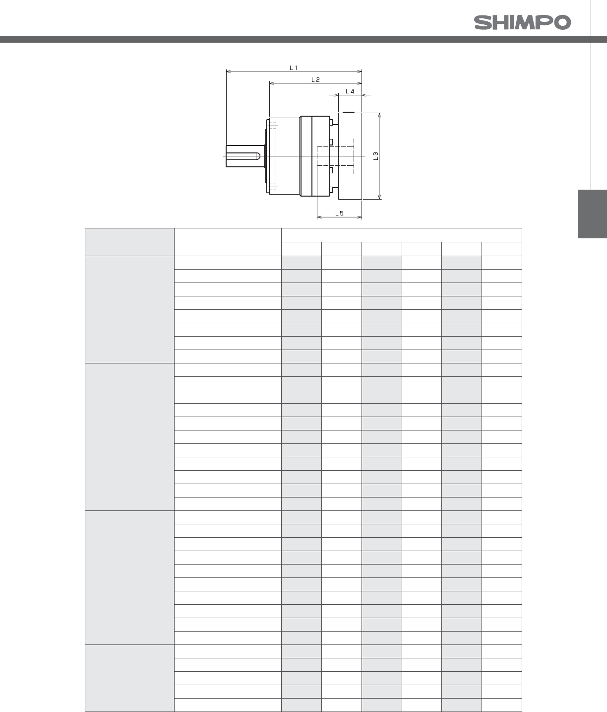
VRB
VRB- 2-Stage Adapter Dimensions
*1) Double reduction : /~ /
Model number **: Adapter code 2-Stage
L1 L* L2 L3 L4 L5
VRB-140-□-□-19**
(Input shaft bore ≦ φ19)
DA•DB•DC 266.5 241.5 169.5 □80 25 50
EB•ED 266.5 241.5 169.5 □90 25 50
FA 266.5 241.5 169.5 □100 25 50
FB 276.5 241.5 179.5 □100 35 60
GB•GD•GJ 266.5 241.5 169.5 □115 25 50
HA 266.5 241.5 169.5 □130 25 50
HB 281.5 241.5 184.5 □130 40 65
JA 276.5 241.5 179.5 □150 35 60
VRB-140-□-□-28**
(Input shaft bore ≦ φ28)
FA•FB•FC 283.5 248.5 186.5 □100 35 67
GA•GB•GC•GD•GE•GF•GG•GH 283.5 248.5 186.5 □115 35 67
HA•HC•HD 283.5 248.5 186.5 □130 35 67
HB 293.5 248.5 196.5 □130 45 77
HF 278.5 248.5 181.5 □130 30 62
JA•JB•JC•JF 283.5 248.5 186.5 □150 35 67
KA•KB•KE 283.5 248.5 186.5 □180 35 67
LA 283.5 248.5 186.5 □200 35 67
LB 293.5 248.5 196.5 □200 45 77
MA 283.5 248.5 186.5 □220 35 67
MB 293.5 248.5 196.5 □220 45 77
VRB-140-□-□-38**
(Input shaft bore ≦ φ38)
HA 298.5 253.5 201.5 □130 45 82
HB•HE 293.5 253.5 196.5 □130 40 77
JA 298.5 253.5 201.5 □150 45 82
KA•KB•KC 298.5 253.5 201.5 □180 45 82
KD 333.5 253.5 236.5 □180 80 117
KE 313.5 253.5 216.5 □180 60 97
LB 308.5 253.5 211.5 □200 55 92
MA•MB 298.5 253.5 201.5 □220 45 82
MC 313.5 253.5 216.5 □220 60 97
MD 308.5 253.5 211.5 □220 55 92
VRB-140-□-□-48**
(Input shaft bore ≦ φ48)
KA 339.5 264.5 242.5 □180 75 118
KB•KC 319.5 264.5 222.5 □180 55 98
LA 319.5 264.5 222.5 □200 55 98
MA 319.5 264.5 222.5 □220 55 98
MB 339.5 264.5 242.5 □220 75 118
A more comprehensive adapter ange o ering can be found using the NIDECSHIMPO Online Selector Tool. The variety is constantly
expanding and being updated on the Selector Tool. If you have any questions or need any support, contact NIDECSHIMPO.
For an explanation on the Adapter Flange Code, please turn to page .
*) Bushing will be inserted to adapt to motor shaft

VRB-SERIES Inline shaft
VRB- 1-Stage Specifications
Frame Size 180
Stage 1-Stage
Ratio Unit Note 3 4 5 6 7 8 9 10
Nominal Output Torque [Nm] *1 500 750 750 750 750 750 500 500
Maximum Acceleration Torque [Nm] *2 970 1400 1400 1400 1400 1400 970 970
Emergency Stop Torque [Nm] *3 2200 2750 2750 2750 2750 2750 2200 2200
Nominal Input Speed [rpm] *4 1500
Maximum Input Speed [rpm] *5 3000
No Load Running Torque [Nm] *6 2.68
Permitted Radial Load [N] *7 5600 6200 6700 7100 7400 7800 8100 8400
Permitted Axial Load [N] *8 4300 4900 5400 5800 6300 6600 7000 7300
Maximum Radial Load [N] *9 15000
Maximum Axial Load [N] *10 14000
Moment of Inertia (≤Ø 28) [kgcm2] -- -- -- -- -- -- -- -- --
Moment of Inertia (≤ Ø 38) [kgcm2] -- 44.000 28.000 22.000 18.000 16.000 15.000 14.000 14.000
Moment of Inertia (≤ Ø 48) [kgcm2] -- 66.000 50.000 44.000 41.000 38.000 37.000 36.000 36.000
Moment of Inertia (≤ Ø 65) [kgcm2] -- 130.000 110.000 100.000 100.000 99.000 97.000 97.000 96.000
E ciency [%] *11 95
Torsional Rigidity [Nm/arc-min] *12 175
Maximum Torsional Backlash [arc-min] -- ≤ 3
Noise Level [dB] *13 67
Protection Class -- *14 IP54 (IP65)
Ambient Temperature [°C] -- 0-40
Permitted Housing Temperature [°C] -- 90
Weight [kg] *15 36
Frame Size 180
Stage 2-Stage
Ratio Unit Note 15 16 20 25 28 30 35 40
Nominal Output Torque [Nm] *1 500 750 750 750 750 500 750 750
Maximum Acceleration Torque [Nm] *2 970 1400 1400 1400 1400 970 1400 1400
Emergency Stop Torque [Nm] *3 2200 2750 2750 2750 2750 2200 2750 2750
Nominal Input Speed [rpm] *4 1500
Maximum Input Speed [rpm] *5 3000
No Load Running Torque [Nm] *6 1.39
Permitted Radial Load [N] *7 9600 9800 11000 11000 12000 12000 13000 13000
Permitted Axial Load [N] *8 8700 8900 9900 11000 11000 12000 13000 13000
Maximum Radial Load [N] *9 15000
Maximum Axial Load [N] *10 14000
Moment of Inertia (≤Ø 28) [kgcm2] -- 4.700 5.400 4.400 4.200 4.900 3.200 4.100 3.200
Moment of Inertia (≤ Ø 38) [kgcm2] -- 12.000 13.000 12.000 12.000 13.000 11.000 12.000 11.000
Moment of Inertia (≤ Ø 48) [kgcm2] -- 34.000 35.000 34.000 34.000 35.000 33.000 34.000 33.000
Moment of Inertia (≤ Ø 65) [kgcm2] -- -- -- -- -- -- -- -- --
E ciency [%] *11 90
Torsional Rigidity [Nm/arc-min] *12 175
Maximum Torsional Backlash [arc-min] -- ≤ 3
Noise Level [dB] *13 67
Protection Class -- *14 IP54 (IP65)
Ambient Temperature [°C] -- 0-40
Permitted Housing Temperature [°C] -- 90
Weight [kg] *15 37
VRB- 2-Stage Specifications

VRB
VRB- 2-Stage Specifications
Frame Size 180
Stage 2-Stage
Ratio Unit Note 45 50 60 70 80 90 100
Nominal Output Torque [Nm] *1 500 750 750 750 750 500 500
Maximum Acceleration Torque [Nm] *2 970 1400 1400 1400 1400 970 970
Emergency Stop Torque [Nm] *3 2200 2750 2750 2750 2750 2200 2200
Nominal Input Speed [rpm] *4 1500
Maximum Input Speed [rpm] *5 3000
No Load Running Torque [Nm] *6 1.39
Permitted Radial Load [N] *7 14000 14000 15000 15000 15000 15000 15000
Permitted Axial Load [N] *8 14000 14000 14000 14000 14000 14000 14000
Maximum Radial Load [N] *9 15000
Maximum Axial Load [N] *10 14000
Moment of Inertia (≤Ø 28) [kgcm2] -- 4.000 3.100 3.100 3.100 3.100 3.100 3.100
Moment of Inertia (≤ Ø 38) [kgcm2] -- 12.000 11.000 11.000 11.000 11.000 11.000 11.000
Moment of Inertia (≤ Ø 48) [kgcm2] -- 34.000 33.000 33.000 33.000 33.000 33.000 33.000
Moment of Inertia (≤ Ø 65) [kgcm2] -- -- -- -- -- -- -- --
E ciency [%] *11 90
Torsional Rigidity [Nm/arc-min] *12 175
Maximum Torsional Backlash [arc-min] -- ≤ 3
Noise Level [dB] *13 67
Protection Class -- *14 IP54 (IP65)
Ambient Temperature [°C] -- 0-40
Permitted Housing Temperature [°C] -- 90
Weight [kg] *15 37
*1) At nominal input speed, service life is , hours
*2) The maximum torque when starting or stopping operation
*3) The maximum torque allowed under a stress situation (Permitted , times during service life)
*4) The average input speed
*5) The maximum intermittent input speed
*6) This is the torque at no load applied on the input shaft. The input speed is , rpm for VRB
*7) At this load and nominal input speed, service life will be , hours. (The radial load applied to the output side bearing)
*8) At this load and nominal input speed, service life will be , hours. (The axial load applied to the output shaft center)
*9) The maximum radial load that the reducer can accept
*10) The maximum axial load that the reducer can accept
*11) The e ciency at the nominal torque rating
*12) This does not include the lost motion
*13) Contact NIDEC-SHIMPO for the testing conditions and environment
*14) IP (wash-down) is available as an option. Contact NIDECSHIMPO for more details and our food grade options
*15) The weight may vary slightly between models

VRB-SERIES Inline shaft
VRB- 1-Stage Dimensions
*1) Length will vary depending on motor
*2) Bushing will be inserted to adapt to motor shaft

VRB
VRB- 2-Stage Dimensions
*1) Length will vary depending on motor
*2) Bushing will be inserted to adapt to motor shaft

VRB-SERIES Inline shaft
VRB- 1-Stage Adapter Dimensions
*1) Single reduction : /~ /
Model number **: Adapter code 1-Stage
L1 L* L2 L3 L4 L5
VRB-180-□-□-28**
(Input shaft bore ≦ φ28)
FA•FB•FC -- -- -- -- -- --
GA•GB•GC•GD•GE•GF•GG•GH -- -- -- -- -- --
HA•HC•HD -- -- -- -- -- --
HB -- -- -- -- -- --
HF -- -- -- -- -- --
JA•JB•JC•JF -- -- -- -- -- --
KA•KB•KE -- -- -- -- -- --
LA -- -- -- -- -- --
LB -- -- -- -- -- --
MA -- -- -- -- -- --
MB -- -- -- -- -- --
VRB-180-□-□-38**
(Input shaft bore ≦ φ38)
HA 286.5 241.5 181.5 □130 45 82
HB•HE 281.5 241.5 176.5 □130 40 77
JA 286.5 241.5 181.5 □150 45 82
KA•KB•KC 286.5 241.5 181.5 □180 45 82
KD 321.5 241.5 216.5 □180 80 117
KE 301.5 241.5 196.5 □180 60 97
MA•MB 286.5 241.5 181.5 □220 45 82
MC 301.5 241.5 196.5 □220 60 97
MD 296.5 241.5 191.5 □220 55 92
NA 286.5 241.5 181.5 □250 45 82
VRB-180-□-□-48**
(Input shaft bore ≦ φ48)
KA 322.5 247.5 217.5 □180 75 118
KB•KC 302.5 247.5 197.5 □180 55 98
LA 302.5 247.5 197.5 □200 55 98
MA 302.5 247.5 197.5 □220 55 98
MB 322.5 247.5 217.5 □220 75 118
NA 322.5 247.5 217.5 □250 75 118
PA 322.5 247.5 217.5 □280 75 118
VRB-180-□-□-65**
(Input shaft bore ≦ φ65)
MA•MB•MC•MD 334 254 229 □220 80 122
NA•NC 334 254 229 □250 80 122
NB•ND 364 254 259 □250 110 152
PA 354 254 249 □280 100 142
PB 364 254 259 □280 110 152
A more comprehensive adapter ange o ering can be found using the NIDECSHIMPO Online Selector Tool. The variety is constantly
expanding and being updated on the Selector Tool. If you have any questions or need any support, contact NIDECSHIMPO.
For an explanation on the Adapter Flange Code, please turn to page .
*) Bushing will be inserted to adapt to motor shaft

VRB
VRB- 2-Stage Adapter Dimensions
*1) Double reduction : /~ /
Model number **: Adapter code 2-Stage
L1 L* L2 L3 L4 L5
VRB-180-□-□-28**
(Input shaft bore ≦ φ28)
FA•FB•FC 316 281 211 □100 35 67
GA•GB•GC•GD•GE•GF•GG•GH 316 281 211 □115 35 67
HA•HC•HD 316 281 211 □130 35 67
HB 326 281 221 □130 45 77
HF 311 281 206 □130 30 62
JA•JB•JC•JF 316 281 211 □150 35 67
KA•KB•KE 316 281 211 □180 35 67
LA 316 281 211 □200 35 67
LB 326 281 221 □200 45 77
MA 316 281 211 □220 35 67
MB 326 281 221 □220 45 77
VRB-180-□-□-38**
(Input shaft bore ≦ φ38)
HA 331 286 226 □130 45 82
HB•HE 326 286 221 □130 40 77
JA 331 286 226 □150 45 82
KA•KB•KC 331 286 226 □180 45 82
KD 366 286 261 □180 80 117
KE 346 286 241 □180 60 97
MA•MB 331 286 226 □220 45 82
MC 346 286 241 □220 60 97
MD 341 286 236 □220 55 92
NA 331 286 226 □250 45 82
VRB-180-□-□-48**
(Input shaft bore ≦ φ48)
KA 367 292 262 □180 75 118
KB•KC 347 292 242 □180 55 98
LA 347 292 242 □200 55 98
MA 347 292 242 □220 55 98
MB 367 292 262 □220 75 118
NA 367 292 262 □250 75 118
PA 367 292 262 □280 75 118
VRB-180-□-□-65**
(Input shaft bore ≦ φ65)
MA•MB•MC•MD -- -- -- -- -- --
NA•NC -- -- -- -- -- --
NB•ND -- -- -- -- -- --
PA -- -- -- -- -- --
PB -- -- -- -- -- --
A more comprehensive adapter ange o ering can be found using the NIDECSHIMPO Online Selector Tool. The variety is constantly
expanding and being updated on the Selector Tool. If you have any questions or need any support, contact NIDECSHIMPO.
For an explanation on the Adapter Flange Code, please turn to page .
*) Bushing will be inserted to adapt to motor shaft

VRB-SERIES Inline shaft
VRB- 1-Stage Specifications
VRB- 2-Stage Specifications
Frame Size 220
Stage 1-Stage
Ratio Unit Note 3 4 5 6 7 8 9 10
Nominal Output Torque [Nm] *1 1000 1500 1500 1500 1500 1500 1000 1000
Maximum Acceleration Torque [Nm] *2 1600 2300 2300 2300 2300 2200 1900 1600
Emergency Stop Torque [Nm] *3 4000 5000 5000 5000 5000 5000 4000 4000
Nominal Input Speed [rpm] *4 1000
Maximum Input Speed [rpm] *5 2000
No Load Running Torque [Nm] *6 2.92
Permitted Radial Load [N] *7 5800 6400 6900 7300 7700 8000 8400 8700
Permitted Axial Load [N] *8 6400 7200 7900 8600 9200 9700 10000 11000
Maximum Radial Load [N] *9 15000
Maximum Axial Load [N] *10 14000
Moment of Inertia (≤ Ø 38) [kgcm2] -- -- -- -- -- -- -- -- --
Moment of Inertia (≤ Ø 48) [kgcm2] -- 90.000 62.000 52.000 47.000 42.000 40.000 39.000 38.000
Moment of Inertia (≤ Ø 65) [kgcm2] -- 150.000 120.000 110.000 110.000 100.000 100.000 99.000 98.000
E ciency [%] *11 97
Torsional Rigidity [Nm/arc-min] *12 400
Maximum Torsional Backlash [arc-min] -- ≤ 3
Noise Level [dB] *13 61
Protection Class -- *14 IP54 (IP65)
Ambient Temperature [°C] -- 0-40
Permitted Housing Temperature [°C] -- 90
Weight [kg] *15 53
Frame Size 220
Stage 2-Stage
Ratio Unit Note 15 16 20 25 28 30 35 40
Nominal Output Torque [Nm] *1 1000 1500 1500 1500 1500 1000 1500 1500
Maximum Acceleration Torque [Nm] *2 1600 2300 2300 2300 2300 1600 2300 2300
Emergency Stop Torque [Nm] *3 4000 5000 5000 5000 5000 4000 5000 5000
Nominal Input Speed [rpm] *4 1000
Maximum Input Speed [rpm] *5 2000
No Load Running Torque [Nm] *6 1.14
Permitted Radial Load [N] *7 9900 10000 11000 12000 12000 13000 13000 14000
Permitted Axial Load [N] *8 13000 13000 14000 14000 14000 14000 14000 14000
Maximum Radial Load [N] *9 15000
Maximum Axial Load [N] *10 14000
Moment of Inertia (≤ Ø 38) [kgcm2] -- 14.000 16.000 14.000 14.000 15.000 12.000 13.000 12.000
Moment of Inertia (≤ Ø 48) [kgcm2] -- 36.000 37.000 35.000 35.000 36.000 34.000 35.000 33.000
Moment of Inertia (≤ Ø 65) [kgcm2] -- -- -- -- -- -- -- -- --
E ciency [%] *11 92
Torsional Rigidity [Nm/arc-min] *12 400
Maximum Torsional Backlash [arc-min] -- ≤ 3
Noise Level [dB] *13 61
Protection Class -- *14 IP54 (IP65)
Ambient Temperature [°C] -- 0-40
Permitted Housing Temperature [°C] -- 90
Weight [kg] *15 54

VRB
VRB- 2-Stage Specifications
Frame Size 220
Stage 2-Stage
Ratio Unit Note 45 50 60 70 80 90 100
Nominal Output Torque [Nm] *1 1000 1500 1500 1500 1500 1000 1000
Maximum Acceleration Torque [Nm] *2 1300 2300 2300 2300 1800 1300 1200
Emergency Stop Torque [Nm] *3 4000 5000 5000 5000 5000 4000 4000
Nominal Input Speed [rpm] *4 1000
Maximum Input Speed [rpm] *5 2000
No Load Running Torque [Nm] *6 1.14
Permitted Radial Load [N] *7 14000 15000 15000 15000 15000 15000 15000
Permitted Axial Load [N] *8 14000 14000 14000 14000 14000 14000 14000
Maximum Radial Load [N] *9 15000
Maximum Axial Load [N] *10 14000
Moment of Inertia (≤ Ø 38) [kgcm2] -- 13.000 12.000 12.000 12.000 12.000 12.000 12.000
Moment of Inertia (≤ Ø 48) [kgcm2] -- 35.000 33.000 33.000 33.000 33.000 33.000 33.000
Moment of Inertia (≤ Ø 65) [kgcm2] -- -- -- -- -- -- -- --
E ciency [%] *11 92
Torsional Rigidity [Nm/arc-min] *12 400
Maximum Torsional Backlash [arc-min] -- ≤ 3
Noise Level [dB] *13 61
Protection Class -- *14 IP54 (IP65)
Ambient Temperature [°C] -- 0-40
Permitted Housing Temperature [°C] -- 90
Weight [kg] *15 54
*1) At nominal input speed, service life is , hours
*2) The maximum torque when starting or stopping operation
*3) The maximum torque allowed under a stress situation (Permitted , times during service life)
*4) The average input speed
*5) The maximum intermittent input speed
*6) This is the torque at no load applied on the input shaft. The input speed is , rpm for VRB
*7) At this load and nominal input speed, service life will be , hours. (The radial load applied to the output side bearing)
*8) At this load and nominal input speed, service life will be , hours. (The axial load applied to the output shaft center)
*9) The maximum radial load that the reducer can accept
*10) The maximum axial load that the reducer can accept
*11) The e ciency at the nominal torque rating
*12) This does not include the lost motion
*13) Contact NIDEC-SHIMPO for the testing conditions and environment
*14) IP (wash-down) is available as an option. Contact NIDECSHIMPO for more details and our food grade options
*15) The weight may vary slightly between models

VRB-SERIES Inline shaft
VRB- 1-Stage Dimensions
*1) Length will vary depending on motor
*2) Bushing will be inserted to adapt to motor shaft

VRB
VRB- 2-Stage Dimensions
*1) Length will vary depending on motor
*2) Bushing will be inserted to adapt to motor shaft

VRB-SERIES Inline shaft
VRB- 1-Stage Adapter Dimensions
*1) Single reduction : /~ /
*2) Bushing will be inserted to adapt to motor shaft
Model number **: Adapter code 1-Stage
L1 L* L2 L3 L4 L5
VRB-220-□-□-38**
(Input shaft bore ≦ φ38)
HA -- -- -- -- -- --
HB•HE -- -- -- -- -- --
JA -- -- -- -- -- --
KA•KB•KC -- -- -- -- -- --
KD -- -- -- -- -- --
KE -- -- -- -- -- --
LA -- -- -- -- -- --
LB -- -- -- -- -- --
MA•MB -- -- -- -- -- --
MC -- -- -- -- -- --
MD -- -- -- -- -- --
NA -- -- -- -- -- --
VRB-220-□-□-48**
(Input shaft bore ≦ φ48)
KA 367.5 292.5 229.5 □180 75 118
KB•KC 347.5 292.5 209.5 □180 55 98
LA 347.5 292.5 209.5 □200 55 98
MA 347.5 292.5 209.5 □220 55 98
MB 367.5 292.5 229.5 □220 75 118
NA 367.5 292.5 229.5 □250 75 118
PA 367.5 292.5 229.5 □280 75 118
VRB-220-□-□-65**
(Input shaft bore ≦ φ65)
MA•MB•MC•MD 371.5 291.5 233.5 □220 80 122
NA•NC 371.5 291.5 233.5 □250 80 122
NB•ND 401.5 291.5 263.5 □250 110 152
PA 391.5 291.5 253.5 □280 100 142
PB 401.5 291.5 263.5 □280 110 152
QA•QB 391.5 291.5 253.5 □320 100 142
A more comprehensive adapter ange o ering can be found using the NIDECSHIMPO Online Selector Tool. The variety is constantly
expanding and being updated on the Selector Tool. If you have any questions or need any support, contact NIDECSHIMPO.
For an explanation on the Adapter Flange Code, please turn to page .

VRB
VRB- 2-Stage Adapter Dimensions
*1) Double reduction : /~ /
*2) Bushing will be inserted to adapt to motor shaft
Model number **: Adapter code 2-Stage
L1 L* L2 L3 L4 L5
VRB-220-□-□-38**
(Input shaft bore ≦ φ38)
HA 366.5 321.5 228.5 □130 45 82
HB•HE 361.5 321.5 223.5 □130 40 77
JA 366.5 321.5 228.5 □150 45 82
KA•KB•KC 366.5 321.5 228.5 □180 45 82
KD 401.5 321.5 263.5 □180 80 117
KE 381.5 321.5 243.5 □180 60 97
LA 366.5 321.5 228.5 □200 45 82
LB 376.5 321.5 238.5 □200 55 92
MA•MB 366.5 321.5 228.5 □220 45 82
MC 381.5 321.5 243.5 □220 60 97
MD 376.5 321.5 238.5 □220 55 92
NA 366.5 321.5 228.5 □250 45 82
VRB-220-□-□-48**
(Input shaft bore ≦ φ48)
KA 402.5 327.5 264.5 □180 75 118
KB•KC 382.5 327.5 244.5 □180 55 98
LA 382.5 327.5 244.5 □200 55 98
MA 382.5 327.5 244.5 □220 55 98
MB 402.5 327.5 264.5 □220 75 118
NA 402.5 327.5 264.5 □250 75 118
PA 402.5 327.5 264.5 □280 75 118
VRB-220-□-□-65**
(Input shaft bore ≦ φ65)
MA•MB•MC•MD -- -- -- -- -- --
NA•NC -- -- -- -- -- --
NB•ND -- -- -- -- -- --
PA -- -- -- -- -- --
PB -- -- -- -- -- --
QA•QB -- -- -- -- -- --
A more comprehensive adapter ange o ering can be found using the NIDECSHIMPO Online Selector Tool. The variety is constantly
expanding and being updated on the Selector Tool. If you have any questions or need any support, contact NIDECSHIMPO.
For an explanation on the Adapter Flange Code, please turn to page .

This planetary series has exceptional load handling capabili-
ties, and it is an ideal selection for higher speed and continu-
ous duty applications. The tapered roller bearings at the output
of the reducer allow the VRS gearbox to handle larger radial and
thrust loads. This internal design provides an extremely smooth
running and quiet reducer even with challenging static forces.
The VRS series is the premier inline series with a maximum arc-min
backlash rating and an output torque peaking at , Nm. The VRS se-
ries is commonly utilized in applications such as higher speed packag-
ing and converting equipment, printing machinery and any servo appli-
cation requiring very low backlash in a more demanding environment.
VRS-SERIES

VRS-SERIES
■Industry standard mounting dimensions
■Large variety of frame sizes and ratios
■Thru-bolt mounting style
■Best-in-class backlash (≤ arc-min)
■Impressive radial and axial load ratings
■Ships in hours in standard frame sizes
■Assembled in the USA
VRS

VRS-SERIES Inline shaft
VRS-Series Features
1 High precision: Standard backlash is arc-min, ideal for higher levels of positional accuracy
2 High rigidity & torque: Rigidity and torque capacity are achieved by using uncaged needle roller bearings
3 High load capacity: Taper roller bearings were added to the output section to increase radial and axial
load ratings
4 Adapter-bushing connection: Enables a simple, e ective attachment to most servo motors
5 No leakage through the seal: High viscosity, anti-separation grease does not liquefy and does not migrate
away from the gears
6 Maintenance-free: No need to replace the grease for the life of the unit. The reducer can be positioned in
any orientation
3
1
2
4
5

VRS
VRS-Series Model Code
Backlash
㩷Adapter ange code
3arc-min3䊶䊶䊶
VR
S 100−B7 3K 19HB16−− −
Output style 㪪㪿㪸㪽㫋㩷㫎㫀㫋㪿㩷㫂㪼㫐
㪪㫄㫆㫆㫋㪿㩷㫊㪿㪸㪽㫋
㪢䊶䊶䊶
㪪䊶䊶䊶
Ratio Single䋺 3㪃㩷4㪃㩷5㪃㩷6㪃㩷7㪃㩷8㪃㩷9㪃㩷10
Double: 15㪃㩷16㪃㩷20㪃㩷25㪃㩷28㪃㩷30㪃㩷35㪃㩷40, 45㪃㩷50㪃㩷60㪃㩷70㪃㩷80㪃㩷90㪃㩷100
Frame size:䇭㪇㪍㪇㪃㩷㪇㪎㪌㪃㩷㪈㪇㪇㪃㩷㪈㪋㪇㪃㩷㪈㪏㪇㪃㩷㪉㪈㪇㪃㩷㪉㪋㪇
Model name for ABLE reducer
Series name VRS Series
Generation of design
*1) Adapter ange code
Adapter ange code varies depending on the motor
Contact us for additional information or refer to our online reducer selection tool.
Selection tool www.nidec-shimpo.co.jp/selection/eng

VRS-SERIES Inline shaft
VRS- 1-Stage Specifications
VRS- 2-Stage Specifications
Frame Size 060
Stage 1-Stage
Ratio Unit Note 3 4 5 6 7 8 9 10
Nominal Output Torque [Nm] *1 18 27 27 27 27 27 18 18
Maximum Acceleration Torque [Nm] *2 35 50 50 50 50 50 35 35
Emergency Stop Torque [Nm] *3 80 100 100 100 100 100 80 80
Nominal Input Speed [rpm] *4 3000
Maximum Input Speed [rpm] *5 6000
No Load Running Torque [Nm] *6 0.15
Permitted Radial Load [N] *7 1700 1900 2000 2100 2200 2300 2400 2400
Permitted Axial Load [N] *8 2300 2500 2700 2700 2700 2700 2700 2700
Maximum Radial Load [N] *9 3000
Maximum Axial Load [N] *10 2700
Moment of Inertia (≤Ø 8) [kgcm2] -- 0.150 0.100 0.080 0.070 0.064 0.060 0.058 0.056
Moment of Inertia (≤ Ø 14) [kgcm2] -- 0.230 0.180 0.160 0.150 0.140 0.140 0.140 0.140
Moment of Inertia (≤ Ø 19) [kgcm2] -- 0.440 0.390 0.370 0.360 0.350 0.350 0.350 0.340
E ciency [%] *11 95
Torsional Rigidity [Nm/arc-min] *12 3
Maximum Torsional Backlash [arc-min] -- ≤ 3
Noise Level [dB] *13 66
Protection Class -- *14 IP54 (IP65)
Ambient Temperature [°C] -- 0-40
Permitted Housing Temperature [°C] -- 90
Weight [kg] *15 1.6
Frame Size 060
Stage 2-Stage
Ratio Unit Note 15 16 20 25 28 30 35 40
Nominal Output Torque [Nm] *1 18 27 27 27 27 18 27 27
Maximum Acceleration Torque [Nm] *2 35 50 50 50 50 35 50 50
Emergency Stop Torque [Nm] *3 80 100 100 100 100 80 100 100
Nominal Input Speed [rpm] *4 3000
Maximum Input Speed [rpm] *5 6000
No Load Running Torque [Nm] *6 0.04
Permitted Radial Load [N] *7 2800 2800 3000 3000 3000 3000 3000 3000
Permitted Axial Load [N] *8 2700 2700 2700 2700 2700 2700 2700 2700
Maximum Radial Load [N] *9 3000
Maximum Axial Load [N] *10 2700
Moment of Inertia (≤Ø 8) [kgcm2] -- 0.055 0.057 0.054 0.053 0.055 0.049 0.053 0.049
Moment of Inertia (≤ Ø 14) [kgcm2] -- 0.140 0.140 0.130 0.130 0.140 0.130 0.130 0.130
Moment of Inertia (≤ Ø 19) [kgcm2] -- -- -- -- -- -- -- -- --
E ciency [%] *11 90
Torsional Rigidity [Nm/arc-min] *12 3
Maximum Torsional Backlash [arc-min] -- ≤ 3
Noise Level [dB] *13 66
Protection Class -- *14 IP54 (IP65)
Ambient Temperature [°C] -- 0-40
Permitted Housing Temperature [°C] -- 90
Weight [kg] *15 1.8

VRS
VRS- 2-Stage Specifications
Frame Size 060
Stage 2-Stage
Ratio Unit Note 45 50 60 70 80 90 100
Nominal Output Torque [Nm] *1 18 27 27 27 27 18 18
Maximum Acceleration Torque [Nm] *2 35 50 50 50 50 35 35
Emergency Stop Torque [Nm] *3 80 100 100 100 100 80 80
Nominal Input Speed [rpm] *4 3000
Maximum Input Speed [rpm] *5 6000
No Load Running Torque [Nm] *6 0.04
Permitted Radial Load [N] *7 3000 3000 3000 3000 3000 3000 3000
Permitted Axial Load [N] *8 2700 2700 2700 2700 2700 2700 2700
Maximum Radial Load [N] *9 3000
Maximum Axial Load [N] *10 2700
Moment of Inertia (≤Ø 8) [kgcm2] -- 0.053 0.049 0.049 0.049 0.049 0.049 0.049
Moment of Inertia (≤ Ø 14) [kgcm2] -- 0.130 0.130 0.130 0.130 0.130 0.130 0.130
Moment of Inertia (≤ Ø 19) [kgcm2] -- -- -- -- -- -- -- --
E ciency [%] *11 90
Torsional Rigidity [Nm/arc-min] *12 3
Maximum Torsional Backlash [arc-min] -- ≤ 3
Noise Level [dB] *13 66
Protection Class -- *14 IP54 (IP65)
Ambient Temperature [°C] -- 0-40
Permitted Housing Temperature [°C] -- 90
Weight [kg] *15 1.8
*1) At nominal input speed, service life is , hours
*2) The maximum torque when starting or stopping operation
*3) The maximum torque allowed under a stress situation (Permitted , times during service life)
*4) The average input speed
*5) The maximum intermittent input speed
*6) This is the torque at no load applied on the input shaft. The input speed is , rpm for VRS
*7) At this load and nominal input speed, service life will be , hours. (The radial load applied to the output side bearing)
*8) At this load and nominal input speed, service life will be , hours. (The axial load applied to the output shaft center)
*9) The maximum radial load that the reducer can accept
*10) The maximum axial load that the reducer can accept
*11) The e ciency at the nominal torque rating
*12) This does not include the lost motion
*13) Contact NIDEC-SHIMPO for the testing conditions and environment
*14) IP (wash-down) is available as an option. Contact NIDECSHIMPO for more details and our food grade options
*15) The weight may vary slightly between models
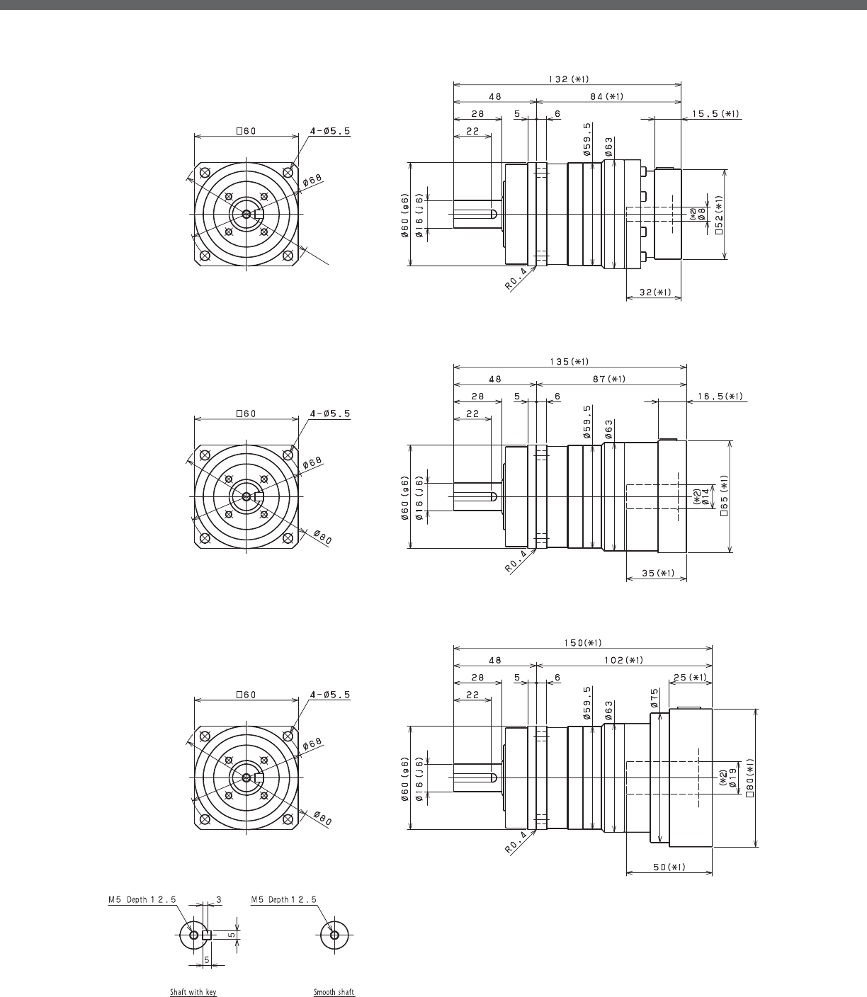
VRS-SERIES Inline shaft
VRS- 1-Stage Dimensions
Input shaft bore䇭㻡φ8
Input shaft bore䇭㻡φ14
Input shaft bore䇭㻡φ19
*1) Length will vary depending on motor
*2) Bushing will be inserted to adapt to motor shaft

VRS
VRS- 2-Stage Dimensions
*1) Length will vary depending on motor
*2) Bushing will be inserted to adapt to motor shaft

VRS-SERIES Inline shaft
VRS- 1-Stage Adapter Dimensions
*1) Single reduction : /~ /
*2) Bushing will be inserted to adapt to motor shaft
Model number **: Adapter code 1-Stage
L1 L* L2 L3 L4 L5
VRS-060-□-□-8**
(Input shaft bore ≦ φ8)
AA•AC•AD•AF•AG•AL•AM•AN•AQ 132 116.5 84 □52 15.5 32
AB•AE•AH•AJ•AK 137 116.5 89 □52 20.5 37
BA•BB•BD•BE•BG•BH•BJ 132 116.5 84 □60 15.5 32
BC•BF 137 116.5 89 □60 20.5 37
CA 137 116.5 89 □70 20.5 37
VRS-060-□-□-14**
(Input shaft bore ≦ φ14)
BA•BB•BD•BE•BF•BG•BH•BJ•BK•BP 135 118.5 87 □65 16.5 35
BC•BH•BM•BN 140 118.5 92 □65 21.5 40
BL 145 118.5 97 □65 26.5 45
CA•CC 135 118.5 87 □70 16.5 35
CB 140 118.5 92 □70 21.5 40
DA•DB•DC•DD•DF•DH•DJ 135 118.5 87 □80 16.5 35
DE•DL 140 118.5 92 □80 21.5 40
DG•DK 145 118.5 97 □80 26.5 45
EA•EB•EC•EF•EG•EK•EL 135 118.5 87 □90 16.5 35
EJ•EM 140 118.5 92 □90 21.5 40
ED•EE•EH 145 118.5 97 □90 26.5 45
FA 135 118.5 87 □100 16.5 35
FB 135 118.5 87 □115 16.5 35
VRS-060-□-□-19**
(Input shaft bore ≦ φ19)
DA•DB•DC 150 125 102 □80 25 50
DD 160 125 112 □80 35 60
DE 155 125 107 □80 30 55
EA 155 125 107 □90 30 55
EB•ED 150 125 102 □90 25 50
EC 160 125 112 □90 35 60
FA 150 125 102 □100 25 50
FB 160 125 112 □100 35 60
A more comprehensive adapter ange o ering can be found using the NIDECSHIMPO Online Selector Tool. The variety is constantly
expanding and being updated on the Selector Tool. If you have any questions or need any support, contact NIDECSHIMPO.
For an explanation on the Adapter Flange Code, please turn to page .

VRS
VRS- 2-Stage Adapter Dimensions
*1) Double reduction : /~ /
*2) Bushing will be inserted to adapt to motor shaft
Model number **: Adapter code 2-Stage
L1 L* L2 L3 L4 L5
VRS-060-□-□-8**
(Input shaft bore ≦ φ8)
AA•AC•AD•AF•AG•AL•AM•AN•AQ 151 135.5 103 □52 15.5 32
AB•AE•AH•AJ•AK 156 135.5 108 □52 20.5 37
BA•BB•BD•BE•BG•BH•BJ 151 135.5 103 □60 15.5 32
BC•BF 156 135.5 108 □60 20.5 37
CA 156 135.5 108 □70 20.5 37
VRS-060-□-□-14**
(Input shaft bore ≦ φ14)
BA•BB•BD•BE•BF•BG•BH•BJ•BK•BP 156 139.5 108 □65 16.5 35
BC•BH•BM•BN 161 139.5 113 □65 21.5 40
BL 166 139.5 118 □65 26.5 45
CA•CC 156 139.5 108 □70 16.5 35
CB 161 139.5 113 □70 21.5 40
DA•DB•DC•DD•DF•DH•DJ 156 139.5 108 □80 16.5 35
DE•DL 161 139.5 113 □80 21.5 40
DG•DK 166 139.5 118 □80 26.5 45
EA•EB•EC•EF•EG•EK•EL 156 139.5 108 □90 16.5 35
EJ•EM 161 139.5 113 □90 21.5 40
ED•EE•EH 166 139.5 118 □90 26.5 45
FA 156 139.5 108 □100 16.5 35
FB 156 139.5 108 □115 16.5 35
VRS-060-□-□-19**
(Input shaft bore ≦ φ19)
DA•DB•DC 171 146 123 □80 25 50
DD 181 146 133 □80 35 60
DE 176 146 128 □80 30 55
EA 176 146 128 □90 30 55
EB•ED 171 146 123 □90 25 50
EC 181 146 133 □90 35 60
FA 171 146 123 □100 25 50
FB 181 146 133 □100 35 60
A more comprehensive adapter ange o ering can be found using the NIDECSHIMPO Online Selector Tool. The variety is constantly
expanding and being updated on the Selector Tool. If you have any questions or need any support, contact NIDECSHIMPO.
For an explanation on the Adapter Flange Code, please turn to page .

VRS-SERIES Inline shaft
VRS- 1-Stage Specifications
VRS- 2-Stage Specifications
Frame Size 075
Stage 1-Stage
Ratio Unit Note 3 4 5 6 7 8 9 10
Nominal Output Torque [Nm] *1 50 75 75 75 75 75 50 50
Maximum Acceleration Torque [Nm] *2 80 125 125 125 125 125 80 80
Emergency Stop Torque [Nm] *3 200 250 250 250 250 250 200 200
Nominal Input Speed [rpm] *4 3000
Maximum Input Speed [rpm] *5 6000
No Load Running Torque [Nm] *6 0.35
Permitted Radial Load [N] *7 2300 2500 2700 2800 3000 3100 3200 3300
Permitted Axial Load [N] *8 3400 3700 3900 3900 3900 3900 3900 3900
Maximum Radial Load [N] *9 4300
Maximum Axial Load [N] *10 3900
Moment of Inertia (≤Ø 8) [kgcm2] -- -- -- -- -- -- -- -- --
Moment of Inertia (≤ Ø 14) [kgcm2] -- 0.670 0.470 0.380 0.340 0.310 0.300 0.290 0.290
Moment of Inertia (≤ Ø 19) [kgcm2] -- 1.100 0.930 0.850 0.810 0.780 0.760 0.750 0.750
Moment of Inertia (≤ Ø 28) [kgcm2] -- 3.100 2.900 2.900 2.800 2.800 2.800 2.800 2.800
E ciency [%] *11 95
Torsional Rigidity [Nm/arc-min] *12 10
Maximum Torsional Backlash [arc-min] -- ≤ 3
Noise Level [dB] *13 67
Protection Class -- *14 IP54 (IP65)
Ambient Temperature [°C] -- 0-40
Permitted Housing Temperature [°C] -- 90
Weight [kg] *15 3.4
Frame Size 075
Stage 2-Stage
Ratio Unit Note 15 16 20 25 28 30 35 40
Nominal Output Torque [Nm] *1 50 75 75 75 75 50 75 75
Maximum Acceleration Torque [Nm] *2 80 125 125 125 125 80 125 125
Emergency Stop Torque [Nm] *3 200 250 250 250 250 200 250 250
Nominal Input Speed [rpm] *4 3000
Maximum Input Speed [rpm] *5 6000
No Load Running Torque [Nm] *6 0.06
Permitted Radial Load [N] *7 3700 3800 4000 4300 4300 4300 4300 4300
Permitted Axial Load [N] *8 3900 3900 3900 3900 3900 3900 3900 3900
Maximum Radial Load [N] *9 4300
Maximum Axial Load [N] *10 3900
Moment of Inertia (≤Ø 8) [kgcm2] -- 0.130 0.140 0.130 0.120 0.140 0.099 0.120 0.098
Moment of Inertia (≤ Ø 14) [kgcm2] -- 0.280 0.300 0.280 0.280 0.290 0.250 0.270 0.250
Moment of Inertia (≤ Ø 19) [kgcm2] -- 0.720 0.730 0.720 0.710 0.730 0.700 0.710 0.690
Moment of Inertia (≤ Ø 28) [kgcm2] -- -- -- -- -- -- -- -- --
E ciency [%] *11 90
Torsional Rigidity [Nm/arc-min] *12 10
Maximum Torsional Backlash [arc-min] -- ≤ 3
Noise Level [dB] *13 67
Protection Class -- *14 IP54 (IP65)
Ambient Temperature [°C] -- 0-40
Permitted Housing Temperature [°C] -- 90
Weight [kg] *15 3.8

VRS
VRS- 2-Stage Specifications
Frame Size 075
Stage 2-Stage
Ratio Unit Note 45 50 60 70 80 90 100
Nominal Output Torque [Nm] *1 50 75 75 75 75 50 50
Maximum Acceleration Torque [Nm] *2 80 125 125 125 125 80 80
Emergency Stop Torque [Nm] *3 200 250 250 250 250 200 200
Nominal Input Speed [rpm] *4 3000
Maximum Input Speed [rpm] *5 6000
No Load Running Torque [Nm] *6 0.06
Permitted Radial Load [N] *7 4300 4300 4300 4300 4300 4300 4300
Permitted Axial Load [N] *8 3900 3900 3900 3900 3900 3900 3900
Maximum Radial Load [N] *9 4300
Maximum Axial Load [N] *10 3900
Moment of Inertia (≤Ø 8) [kgcm2] -- 0.120 0.098 0.098 0.097 0.097 0.097 0.097
Moment of Inertia (≤ Ø 14) [kgcm2] -- 0.270 0.250 0.250 0.250 0.250 0.250 0.250
Moment of Inertia (≤ Ø 19) [kgcm2] -- 0.710 0.690 0.690 0.690 0.690 0.690 0.690
Moment of Inertia (≤ Ø 28) [kgcm2] -- -- -- -- -- -- -- --
E ciency [%] *11 90
Torsional Rigidity [Nm/arc-min] *12 10
Maximum Torsional Backlash [arc-min] -- ≤ 3
Noise Level [dB] *13 67
Protection Class -- *14 IP54 (IP65)
Ambient Temperature [°C] -- 0-40
Permitted Housing Temperature [°C] -- 90
Weight [kg] *15 3.8
*1) At nominal input speed, service life is , hours
*2) The maximum torque when starting or stopping operation
*3) The maximum torque allowed under a stress situation (Permitted , times during service life)
*4) The average input speed
*5) The maximum intermittent input speed
*6) This is the torque at no load applied on the input shaft. The input speed is , rpm for VRS
*7) At this load and nominal input speed, service life will be , hours. (The radial load applied to the output side bearing)
*8) At this load and nominal input speed, service life will be , hours. (The axial load applied to the output shaft center)
*9) The maximum radial load that the reducer can accept
*10) The maximum axial load that the reducer can accept
*11) The e ciency at the nominal torque rating
*12) This does not include the lost motion
*13) Contact NIDEC-SHIMPO for the testing conditions and environment
*14) IP (wash-down) is available as an option. Contact NIDECSHIMPO for more details and our food grade options
*15) The weight may vary slightly between models

VRS-SERIES Inline shaft
VRS- 1-Stage Dimensions
*1) Length will vary depending on motor
*2) Bushing will be inserted to adapt to motor shaft

VRS
VRS- 2-Stage Dimensions
*1) Length will vary depending on motor
*2) Bushing will be inserted to adapt to motor shaft
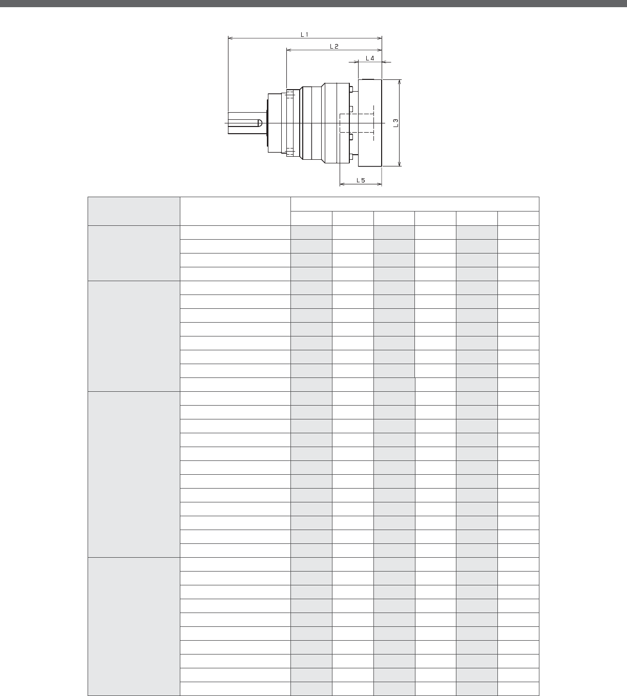
VRS-SERIES Inline shaft
VRS- 1-Stage Adapter Dimensions
*1) Single reduction : /~ /
Model number **: Adapter code 1-Stage
L1 L* L2 L3 L4 L5
VRS-075-□-□-8**
(Input shaft bore ≦ φ8)
AA•AC•AD•AF•AG•AL•AM•AN•AQ -- -- -- -- -- --
AB•AE•AH•AJ•AK -- -- -- -- -- --
BA•BB•BD•BE•BG•BH•BJ -- -- -- -- -- --
CA -- -- -- -- -- --
VRS-075-□-□-14**
(Input shaft bore ≦ φ14)
BA•BB•BD•BE•BF•BG•BH•BJ•BK•BP 164.5 148 108.5 □65 16.5 35
BC•BH•BM•BN 169.5 148 113.5 □65 21.5 40
CA•CC 164.5 148 108.5 □70 16.5 35
DA•DB•DC•DD•DF•DH•DJ 164.5 148 108.5 □80 16.5 35
EA•EB•EC•EF•EG•EK•EL 164.5 148 108.5 □90 16.5 35
FA 164.5 148 108.5 □100 16.5 35
FB 174.5 148 118.5 □100 26.5 45
JA 179.5 148 123.5 □150 31.5 50
VRS-075-□-□-19**
(Input shaft bore ≦ φ19)
DA•DB•DC 174.5 149.5 118.5 □80 25 50
EB•ED 174.5 149.5 118.5 □90 25 50
FA 174.5 149.5 118.5 □100 25 50
FB 184.5 149.5 128.5 □100 35 60
GA•GC•GH 179.5 149.5 123.5 □115 30 55
GB•GD•GJ 174.5 149.5 118.5 □115 25 50
GE•GF 184.5 149.5 128.5 □115 35 60
HA 174.5 149.5 118.5 □130 25 50
HB 189.5 149.5 133.5 □130 40 65
HC•HD•HE 179.5 149.5 123.5 □130 30 55
JA 184.5 149.5 128.5 □150 35 60
JB 189.5 149.5 133.5 □150 40 65
VRS-075-□-□-28**
(Input shaft bore ≦ φ28)
FA•FB•FC 191.5 156.5 135.5 □100 35 67
FD•FE 186.5 156.5 130.5 □100 30 62
GA•GB•GC•GD•GE•GF•GG•GH 191.5 156.5 135.5 □115 35 67
HA•HC•HD 191.5 156.5 135.5 □130 35 67
HB 201.5 156.5 145.5 □130 45 77
HE 206.5 156.5 150.5 □130 50 82
HF 186.5 156.5 130.5 □130 30 62
JA•JB•JC•JF 191.5 156.5 135.5 □150 35 67
JD 211.5 156.5 155.5 □150 55 87
JE 201.5 156.5 145.5 □150 45 77
A more comprehensive adapter ange o ering can be found using the NIDECSHIMPO Online Selector Tool. The variety is constantly
expanding and being updated on the Selector Tool. If you have any questions or need any support, contact NIDECSHIMPO.
For an explanation on the Adapter Flange Code, please turn to page .
*) Bushing will be inserted to adapt to motor shaft

VRS
VRS- 2-Stage Adapter Dimensions
*1) Double reduction : /~ /
Model number **: Adapter code 2-Stage
L1 L* L2 L3 L4 L5
VRS-075-□-□-8**
(Input shaft bore ≦ φ8)
AA•AC•AD•AF•AG•AL•AM•AN•AQ 181.5 166 125.5 □52 15.5 32
AB•AE•AH•AJ•AK 186.5 166 130.5 □52 20.5 37
BA•BB•BD•BE•BG•BH•BJ 181.5 166 125.5 □60 15.5 32
CA 186.5 166 130.5 □70 20.5 37
VRS-075-□-□-14**
(Input shaft bore ≦ φ14)
BA•BB•BD•BE•BF•BG•BH•BJ•BK•BP 186.5 170 130.5 □65 16.5 35
BC•BH•BM•BN 191.5 170 135.5 □65 21.5 40
CA•CC 186.5 170 130.5 □70 16.5 35
DA•DB•DC•DD•DF•DH•DJ 186.5 170 130.5 □80 16.5 35
EA•EB•EC•EF•EG•EK•EL 186.5 170 130.5 □90 16.5 35
FA 186.5 170 130.5 □100 16.5 35
FB 196.5 170 140.5 □100 26.5 45
JA 201.5 170 145.5 □150 31.5 50
VRS-075-□-□-19**
(Input shaft bore ≦ φ19)
DA•DB•DC 196.5 171.5 140.5 □80 25 50
EB•ED 196.5 171.5 140.5 □90 25 50
FA 196.5 171.5 140.5 □100 25 50
FB 206.5 171.5 150.5 □100 35 60
GA•GC•GH 201.5 171.5 145.5 □115 30 55
GB•GD•GJ 196.5 171.5 140.5 □115 25 50
GE•GF 206.5 171.5 150.5 □115 35 60
HA 196.5 171.5 140.5 □130 25 50
HB 211.5 171.5 155.5 □130 40 65
HC•HD•HE 201.5 171.5 145.5 □130 30 55
JA 206.5 171.5 150.5 □150 35 60
JB 211.5 171.5 155.5 □150 40 65
VRS-075-□-□-28**
(Input shaft bore ≦ φ28)
FA•FB•FC 215.5 180.5 159.5 □100 35 67
FD•FE 210.5 180.5 154.5 □100 30 62
GA•GB•GC•GD•GE•GF•GG•GH 215.5 180.5 159.5 □115 35 67
HA•HC•HD 215.5 180.5 159.5 □130 35 67
HB 225.5 180.5 169.5 □130 45 77
HE 230.5 180.5 174.5 □130 50 82
HF 210.5 180.5 154.5 □130 30 62
JA•JB•JC•JF 215.5 180.5 159.5 □150 35 67
JD 235.5 180.5 179.5 □150 55 87
JE 225.5 180.5 169.5 □150 45 77
A more comprehensive adapter ange o ering can be found using the NIDECSHIMPO Online Selector Tool. The variety is constantly
expanding and being updated on the Selector Tool. If you have any questions or need any support, contact NIDECSHIMPO.
For an explanation on the Adapter Flange Code, please turn to page .
*) Bushing will be inserted to adapt to motor shaft

VRS-SERIES Inline shaft
VRS- 1-Stage Specifications
VRS- 2-Stage Specifications
Frame Size 100
Stage 1-Stage
Ratio Unit Note 3 4 5 6 7 8 9 10
Nominal Output Torque [Nm] *1 120 120 180 180 180 180 120 120
Maximum Acceleration Torque [Nm] *2 225 330 330 330 330 330 225 225
Emergency Stop Torque [Nm] *3 500 625 625 625 625 625 500 500
Nominal Input Speed [rpm] *4 3000
Maximum Input Speed [rpm] *5 6000
No Load Running Torque [Nm] *6 1.30
Permitted Radial Load [N] *7 3400 3700 4000 4200 4400 4600 4800 4900
Permitted Axial Load [N] *8 4800 5200 5600 5900 6100 6300 6300 6300
Maximum Radial Load [N] *9 7000
Maximum Axial Load [N] *10 6300
Moment of Inertia (≤Ø 14) [kgcm2] -- -- -- -- -- -- -- -- --
Moment of Inertia (≤ Ø 19) [kgcm2] -- 3.200 2.000 1.500 1.300 1.100 1.000 0.960 0.930
Moment of Inertia (≤ Ø 28) [kgcm2] -- 5.200 4.000 3.600 3.300 3.100 3.000 3.000 3.000
Moment of Inertia (≤ Ø 38) [kgcm2] -- 13.000 12.000 11.000 11.000 11.000 11.000 11.000 11.000
E ciency [%] *11 95
Torsional Rigidity [Nm/arc-min] *12 31
Maximum Torsional Backlash [arc-min] -- ≤ 3
Noise Level [dB] *13 71
Protection Class -- *14 IP54 (IP65)
Ambient Temperature [°C] -- 0-40
Permitted Housing Temperature [°C] -- 90
Weight [kg] *15 8.1
Frame Size 100
Stage 2-Stage
Ratio Unit Note 15 16 20 25 28 30 35 40
Nominal Output Torque [Nm] *1 120 180 180 180 180 120 180 180
Maximum Acceleration Torque [Nm] *2 225 330 330 330 330 225 330 330
Emergency Stop Torque [Nm] *3 500 625 625 625 625 500 625 625
Nominal Input Speed [rpm] *4 3000
Maximum Input Speed [rpm] *5 6000
No Load Running Torque [Nm] *6 0.42
Permitted Radial Load [N] *7 5600 5700 6100 6500 6700 6900 7000 7000
Permitted Axial Load [N] *8 6300 6300 6300 6300 6300 6300 6300 6300
Maximum Radial Load [N] *9 7000
Maximum Axial Load [N] *10 6300
Moment of Inertia (≤Ø 14) [kgcm2] -- 0.420 0.480 0.400 0.380 0.440 0.290 0.370 0.280
Moment of Inertia (≤ Ø 19) [kgcm2] -- 0.860 0.910 0.830 0.820 0.870 0.740 0.810 0.730
Moment of Inertia (≤ Ø 28) [kgcm2] -- 2.800 2.900 2.800 2.800 2.800 2.700 2.700 2.700
Moment of Inertia (≤ Ø 38) [kgcm2] -- -- -- -- -- -- -- -- --
E ciency [%] *11 90
Torsional Rigidity [Nm/arc-min] *12 31
Maximum Torsional Backlash [arc-min] -- ≤ 3
Noise Level [dB] *13 71
Protection Class -- *14 IP54 (IP65)
Ambient Temperature [°C] -- 0-40
Permitted Housing Temperature [°C] -- 90
Weight [kg] *15 8.8

VRS
VRS- 2-Stage Specifications
Frame Size 100
Stage 2-Stage
Ratio Unit Note 45 50 60 70 80 90 100
Nominal Output Torque [Nm] *1 120 180 180 180 180 120 120
Maximum Acceleration Torque [Nm] *2 225 330 330 330 330 225 225
Emergency Stop Torque [Nm] *3 500 625 625 625 625 500 500
Nominal Input Speed [rpm] *4 3000
Maximum Input Speed [rpm] *5 6000
No Load Running Torque [Nm] *6 0.42
Permitted Radial Load [N] *7 7000 7000 7000 7000 7000 7000 7000
Permitted Axial Load [N] *8 6300 6300 6300 6300 6300 6300 6300
Maximum Radial Load [N] *9 7000
Maximum Axial Load [N] *10 6300
Moment of Inertia (≤Ø 14) [kgcm2] -- 0.370 0.280 0.280 0.280 0.280 0.270 0.270
Moment of Inertia (≤ Ø 19) [kgcm2] -- 0.800 0.730 0.730 0.730 0.730 0.730 0.730
Moment of Inertia (≤ Ø 28) [kgcm2] -- 2.700 2.700 2.700 2.700 2.700 2.700 2.700
Moment of Inertia (≤ Ø 38) [kgcm2] -- -- -- -- -- -- -- --
E ciency [%] *11 90
Torsional Rigidity [Nm/arc-min] *12 31
Maximum Torsional Backlash [arc-min] -- ≤ 3
Noise Level [dB] *13 71
Protection Class -- *14 IP54 (IP65)
Ambient Temperature [°C] -- 0-40
Permitted Housing Temperature [°C] -- 90
Weight [kg] *15 8.8
*1) At nominal input speed, service life is , hours
*2) The maximum torque when starting or stopping operation
*3) The maximum torque allowed under a stress situation (Permitted , times during service life)
*4) The average input speed
*5) The maximum intermittent input speed
*6) This is the torque at no load applied on the input shaft. The input speed is , rpm for VRS
*7) At this load and nominal input speed, service life will be , hours. (The radial load applied to the output side bearing)
*8) At this load and nominal input speed, service life will be , hours. (The axial load applied to the output shaft center)
*9) The maximum radial load that the reducer can accept
*10) The maximum axial load that the reducer can accept
*11) The e ciency at the nominal torque rating
*12) This does not include the lost motion
*13) Contact NIDEC-SHIMPO for the testing conditions and environment
*14) IP (wash-down) is available as an option. Contact NIDECSHIMPO for more details and our food grade options
*15) The weight may vary slightly between models

VRS-SERIES Inline shaft
VRS- 1-Stage Dimensions
*1) Length will vary depending on motor
*2) Bushing will be inserted to adapt to motor shaft

VRS
VRS- 2-Stage Dimensions
*1) Length will vary depending on motor
*2) Bushing will be inserted to adapt to motor shaft

VRS-SERIES Inline shaft
VRS- 1-Stage Adapter Dimensions
*1) Single reduction : /~ /
Model number **: Adapter code 1-Stage
L1 L* L2 L3 L4 L5
VRS-100-□-□-14**
(Input shaft bore ≦ φ14)
BA•BB•BD•BE•BF•BG•BH•BJ•BK•BP -- -- -- -- -- --
BC•BH•BM•BN -- -- -- -- -- --
CA•CC ------------
DA•DB•DC•DD•DF•DH•DJ -- -- -- -- -- --
EA•EB•EC•EF•EG•EK•EL -- -- -- -- -- --
FA -- -- -- -- -- --
FB -- -- -- -- -- --
JA -- -- -- -- -- --
VRS-100-□-□-19**
(Input shaft bore ≦ φ19)
DA•DB•DC 213.5 188.5 125.5 □80 25 50
EB 213.5 188.5 125.5 □90 25 50
FA 213.5 188.5 125.5 □100 25 50
FB 223.5 188.5 135.5 □100 35 60
GB•GD 213.5 188.5 125.5 □115 25 50
HA 223.5 188.5 135.5 □115 35 60
-- 213.5 188.5 125.5 □130 25 50
-- 228.5 188.5 140.5 □130 40 65
-- 218.5 188.5 130.5 □130 30 55
HB 223.5 188.5 135.5 □150 35 60
VRS-100-□-□-28**
(Input shaft bore ≦ φ28)
FA•FB•FC 230.5 195.5 142.5 □100 35 67
GA•GB•GC•GD•GE•GF•GG•GH 230.5 195.5 142.5 □115 35 67
HA•HC•HD 230.5 195.5 142.5 □130 35 67
HB 240.5 195.5 152.5 □130 45 77
HF 225.5 195.5 137.5 □130 30 62
JA•JB•JC•JF 230.5 195.5 142.5 □150 35 67
JD 250.5 195.5 162.5 □150 55 87
JE 240.5 195.5 152.5 □150 45 77
KA•KB•KE 230.5 195.5 142.5 □180 35 67
KD 240.5 195.5 152.5 □180 45 77
VRS-100-□-□-38**
(Input shaft bore ≦ φ38)
HA 251.5 206.5 163.5 □130 45 82
HB•HE 246.5 206.5 158.5 □130 40 77
JA 251.5 206.5 163.5 □150 45 82
KA•KB•KC 251.5 206.5 163.5 □180 45 82
KD 286.5 206.5 198.5 □180 80 117
KE 266.5 206.5 178.5 □180 60 97
A more comprehensive adapter ange o ering can be found using the NIDECSHIMPO Online Selector Tool. The variety is constantly
expanding and being updated on the Selector Tool. If you have any questions or need any support, contact NIDECSHIMPO.
For an explanation on the Adapter Flange Code, please turn to page .
*) Bushing will be inserted to adapt to motor shaft

VRS
VRS- 2-Stage Adapter Dimensions
*1) Double reduction : /~ /
Model number **: Adapter code 2-Stage
L1 L* L2 L3 L4 L5
VRS-100-□-□-14**
(Input shaft bore ≦ φ14)
BA•BB•BD•BE•BF•BG•BH•BJ•BK•BP 231 214.5 143 □65 16.5 35
BC•BH•BM•BN 236 214.5 148 □65 21.5 40
CA•CC 231 214.5 143 □70 16.5 35
DA•DB•DC•DD•DF•DH•DJ 231 214.5 143 □80 16.5 35
EA•EB•EC•EF•EG•EK•EL 231 214.5 143 □90 16.5 35
FA 231 214.5 143 □100 16.5 35
FB 241 214.5 153 □100 26.5 45
JA 246 214.5 158 □150 31.5 50
VRS-100-□-□-19**
(Input shaft bore ≦ φ19)
DA•DB•DC 241 216 153 □80 25 50
EB 241 216 153 □90 25 50
FA 241 216 153 □100 25 50
FB 251 216 163 □100 35 60
GB•GD 241 216 153 □115 25 50
HA 251 216 163 □115 35 60
-- 241 216 153 □130 25 50
-- 256 216 168 □130 40 65
-- 246 216 158 □130 30 55
HB 251 216 163 □150 35 60
VRS-100-□-□-28**
(Input shaft bore ≦ φ28)
FA•FB•FC 258 223 170 □100 35 67
GA•GB•GC•GD•GE•GF•GG•GH 258 223 170 □115 35 67
HA•HC•HD 258 223 170 □130 35 67
HB 268 223 180 □130 45 77
HF 253 223 165 □130 30 62
JA•JB•JC•JF 258 223 170 □150 35 67
JD 278 223 190 □150 55 87
JE 268 223 180 □150 45 77
KA•KB•KE 258 223 170 □180 35 67
KD 268 223 180 □180 45 77
VRS-100-□-□-38**
(Input shaft bore ≦ φ38)
HA 275.5 230.5 187.5 □130 45 82
HB•HE 270.5 230.5 182.5 □130 40 77
JA 275.5 230.5 187.5 □150 45 82
KA•KB•KC 275.5 230.5 187.5 □180 45 82
KD 310.5 230.5 222.5 □180 80 117
KE 290.5 230.5 202.5 □180 60 97
A more comprehensive adapter ange o ering can be found using the NIDECSHIMPO Online Selector Tool. The variety is constantly
expanding and being updated on the Selector Tool. If you have any questions or need any support, contact NIDECSHIMPO.
For an explanation on the Adapter Flange Code, please turn to page .
*) Bushing will be inserted to adapt to motor shaft

VRS-SERIES Inline shaft
VRS- 1-Stage Specifications
VRS- 2-Stage Specifications
Frame Size 140
Stage 1-Stage
Ratio Unit Note 3 4 5 6 7 8 9 10
Nominal Output Torque [Nm] *1 240 240 360 360 360 360 240 240
Maximum Acceleration Torque [Nm] *2 470 700 700 700 700 700 470 470
Emergency Stop Torque [Nm] *3 1000 1250 1250 1250 1250 1250 1000 1000
Nominal Input Speed [rpm] *4 2000
Maximum Input Speed [rpm] *5 4000
No Load Running Torque [Nm] *6 1.63
Permitted Radial Load [N] *7 6700 7400 7900 8300 8700 9100 9400 9700
Permitted Axial Load [N] *8 9000 9000 9000 9000 9000 9000 9000 9000
Maximum Radial Load [N] *9 10000
Maximum Axial Load [N] *10 9000
Moment of Inertia (≤Ø 19) [kgcm2] -- -- -- -- -- -- -- -- --
Moment of Inertia (≤ Ø 28) [kgcm2] -- 12.000 7.400 5.800 4.900 4.100 3.800 3.600 3.400
Moment of Inertia (≤ Ø 38) [kgcm2] -- 20.000 15.000 13.000 13.000 12.000 12.000 11.000 11.000
Moment of Inertia (≤ Ø 48) [kgcm2] -- 42.000 37.000 36.000 35.000 34.000 34.000 34.000 33.000
E ciency [%] *11 95
Torsional Rigidity [Nm/arc-min] *12 60
Maximum Torsional Backlash [arc-min] -- ≤ 3
Noise Level [dB] *13 67
Protection Class -- *14 IP54 (IP65)
Ambient Temperature [°C] -- 0-40
Permitted Housing Temperature [°C] -- 90
Weight [kg] *15 17
Frame Size 140
Stage 2-Stage
Ratio Unit Note 15 16 20 25 28 30 35 40
Nominal Output Torque [Nm] *1 240 360 360 360 360 240 360 360
Maximum Acceleration Torque [Nm] *2 470 700 700 700 700 470 700 700
Emergency Stop Torque [Nm] *3 1000 1250 1250 1250 1250 1000 1250 1250
Nominal Input Speed [rpm] *4 2000
Maximum Input Speed [rpm] *5 4000
No Load Running Torque [Nm] *6 0.56
Permitted Radial Load [N] *7 10000 10000 10000 10000 10000 10000 10000 10000
Permitted Axial Load [N] *8 9000 9000 9000 9000 9000 9000 9000 9000
Maximum Radial Load [N] *9 10000
Maximum Axial Load [N] *10 9000
Moment of Inertia (≤Ø 19) [kgcm2] -- 1.300 1.500 1.200 1.100 1.400 0.850 1.100 0.830
Moment of Inertia (≤ Ø 28) [kgcm2] -- 3.200 3.500 3.100 3.100 3.300 2.800 3.100 2.800
Moment of Inertia (≤ Ø 38) [kgcm2] -- 11.000 11.000 11.000 11.000 11.000 10.000 11.000 10.000
Moment of Inertia (≤ Ø 48) [kgcm2] -- -- -- -- -- -- -- -- --
E ciency [%] *11 90
Torsional Rigidity [Nm/arc-min] *12 60
Maximum Torsional Backlash [arc-min] -- ≤ 3
Noise Level [dB] *13 67
Protection Class -- *14 IP54 (IP65)
Ambient Temperature [°C] -- 0-40
Permitted Housing Temperature [°C] -- 90
Weight [kg] *15 19

VRS
VRS- 2-Stage Specifications
Frame Size 140
Stage 2-Stage
Ratio Unit Note 45 50 60 70 80 90 100
Nominal Output Torque [Nm] *1 240 360 360 360 360 240 240
Maximum Acceleration Torque [Nm] *2 470 700 700 700 700 470 470
Emergency Stop Torque [Nm] *3 1000 1250 1250 1250 1250 1000 1000
Nominal Input Speed [rpm] *4 2000
Maximum Input Speed [rpm] *5 4000
No Load Running Torque [Nm] *6 0.56
Permitted Radial Load [N] *7 10000 10000 10000 10000 10000 10000 10000
Permitted Axial Load [N] *8 9000 9000 9000 9000 9000 9000 9000
Maximum Radial Load [N] *9 10000
Maximum Axial Load [N] *10 9000
Moment of Inertia (≤Ø 19) [kgcm2] -- 1.100 0.810 0.810 0.800 0.800 0.800 0.800
Moment of Inertia (≤ Ø 28) [kgcm2] -- 3.000 2.800 2.800 2.800 2.800 2.800 2.800
Moment of Inertia (≤ Ø 38) [kgcm2] -- 11.000 10.000 10.000 10.000 10.000 10.000 10.000
Moment of Inertia (≤ Ø 48) [kgcm2] -- -- -- -- -- -- -- --
E ciency [%] *11 90
Torsional Rigidity [Nm/arc-min] *12 60
Maximum Torsional Backlash [arc-min] -- ≤ 3
Noise Level [dB] *13 67
Protection Class -- *14 IP54 (IP65)
Ambient Temperature [°C] -- 0-40
Permitted Housing Temperature [°C] -- 90
Weight [kg] *15 19
*1) At nominal input speed, service life is , hours
*2) The maximum torque when starting or stopping operation
*3) The maximum torque allowed under a stress situation (Permitted , times during service life)
*4) The average input speed
*5) The maximum intermittent input speed
*6) This is the torque at no load applied on the input shaft. The input speed is , rpm for VRS
*7) At this load and nominal input speed, service life will be , hours. (The radial load applied to the output side bearing)
*8) At this load and nominal input speed, service life will be , hours. (The axial load applied to the output shaft center)
*9) The maximum radial load that the reducer can accept
*10) The maximum axial load that the reducer can accept
*11) The e ciency at the nominal torque rating
*12) This does not include the lost motion
*13) Contact NIDEC-SHIMPO for the testing conditions and environment
*14) IP (wash-down) is available as an option. Contact NIDECSHIMPO for more details and our food grade options
*15) The weight may vary slightly between models

VRS-SERIES Inline shaft
VRS- 1-Stage Dimensions
*1) Length will vary depending on motor
*2) Bushing will be inserted to adapt to motor shaft

VRS
VRS- 2-Stage Dimensions
*1) Length will vary depending on motor
*2) Bushing will be inserted to adapt to motor shaft

VRS-SERIES Inline shaft
VRS- 1-Stage Adapter Dimensions
*1) Single reduction : /~ /
Model number **: Adapter code 1-Stage
L1 L* L2 L3 L4 L5
VRS-140-□-□-19**
(Input shaft bore ≦ φ19)
DA•DB•DC -- -- -- -- -- --
EB•ED -- -- -- -- -- --
FA -- -- -- -- -- --
FB -- -- -- -- -- --
GB•GD•GJ -- -- -- -- -- --
HA -- -- -- -- -- --
HB -- -- -- -- -- --
JA -- -- -- -- -- --
VRS-140-□-□-28**
(Input shaft bore ≦ φ28)
FA•FB•FC 274 239 162 □100 35 67
GA•GB•GC•GD•GE•GF•GG•GH 274 239 162 □115 35 67
HA•HC•HD 274 239 162 □130 35 67
HB 284 239 172 □130 45 77
HF 269 239 157 □130 30 62
JA•JB•JC•JF 274 239 162 □150 35 67
KA•KB•KE 274 239 162 □180 35 67
LA 274 239 162 □200 35 67
LB 284 239 172 □200 45 77
MA 274 239 162 □220 35 67
MB 284 239 172 □220 45 77
VRS-140-□-□-38**
(Input shaft bore ≦ φ38)
HA 289 244 177 □130 45 82
HB•HE 284 244 172 □130 40 77
JA 289 244 177 □150 45 82
KA•KB•KC 289 244 177 □180 45 82
KD 324 244 212 □180 80 117
KE 304 244 192 □180 60 97
LB 299 244 187 □200 55 92
MA•MB 289 244 177 □220 45 82
MC 304 244 192 □220 60 97
MD 299 244 187 □220 55 92
VRS-140-□-□-48**
(Input shaft bore ≦ φ48)
KA 330 255 218 □180 75 118
KB•KC 310 255 198 □180 55 98
LA 310 255 198 □200 55 98
MA 310 255 198 □220 55 98
MB 330 255 218 □220 75 118
A more comprehensive adapter ange o ering can be found using the NIDECSHIMPO Online Selector Tool. The variety is constantly
expanding and being updated on the Selector Tool. If you have any questions or need any support, contact NIDECSHIMPO.
For an explanation on the Adapter Flange Code, please turn to page .
*) Bushing will be inserted to adapt to motor shaft
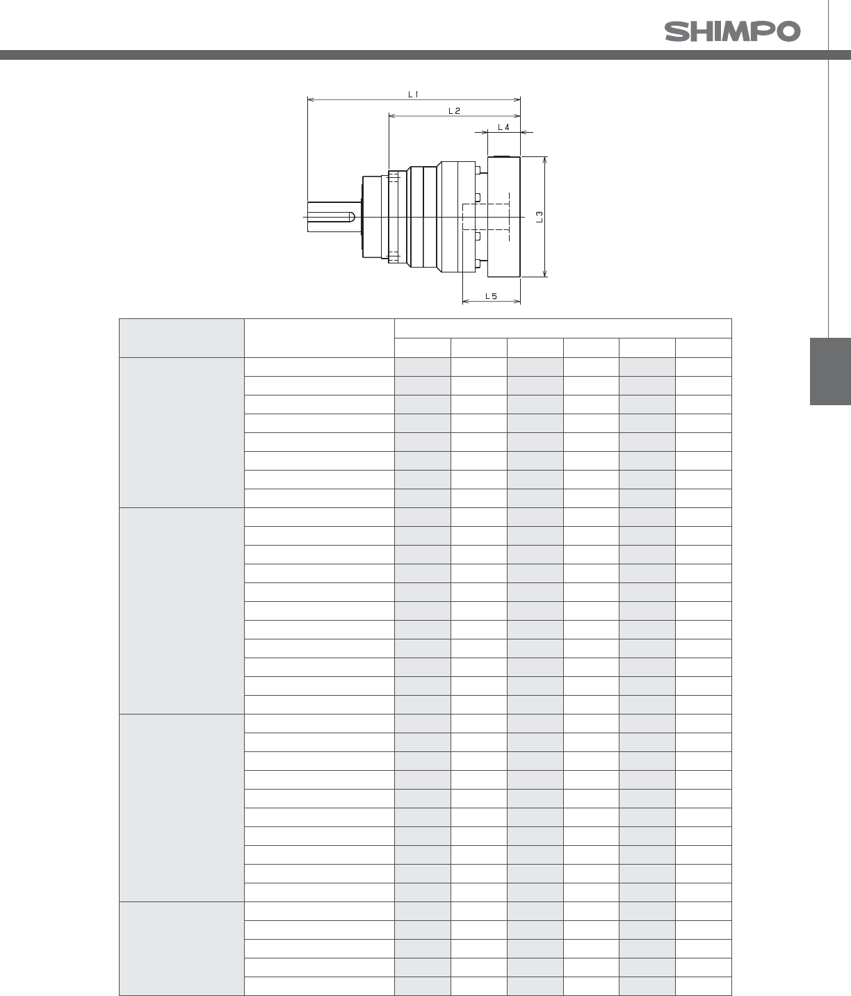
VRS
VRS- 2-Stage Adapter Dimensions
*1) Double reduction : /~ /
Model number **: Adapter code 2-Stage
L1 L* L2 L3 L4 L5
VRS-140-□-□-19**
(Input shaft bore ≦ φ19)
DA•DB•DC 291.5 266.5 179.5 □80 25 50
EB•ED 291.5 266.5 179.5 □90 25 50
FA 291.5 266.5 179.5 □100 25 50
FB 301.5 266.5 189.5 □100 35 60
GB•GD•GJ 291.5 266.5 179.5 □115 25 50
HA 291.5 266.5 179.5 □130 25 50
HB 306.5 266.5 194.5 □130 40 65
JA 301.5 266.5 189.5 □150 35 60
VRS-140-□-□-28**
(Input shaft bore ≦ φ28)
FA•FB•FC 308.5 273.5 196.5 □100 35 67
GA•GB•GC•GD•GE•GF•GG•GH 308.5 273.5 196.5 □115 35 67
HA•HC•HD 308.5 273.5 196.5 □130 35 67
HB 318.5 273.5 206.5 □130 45 77
HF 303.5 273.5 191.5 □130 30 62
JA•JB•JC•JF 308.5 273.5 196.5 □150 35 67
KA•KB•KE 308.5 273.5 196.5 □180 35 67
LA 308.5 273.5 196.5 □200 35 67
LB 318.5 273.5 206.5 □200 45 77
MA 308.5 273.5 196.5 □220 35 67
MB 318.5 273.5 206.5 □220 45 77
VRS-140-□-□-38**
(Input shaft bore ≦ φ38)
HA 323.5 278.5 211.5 □130 45 82
HB•HE 318.5 278.5 206.5 □130 40 77
JA 323.5 278.5 211.5 □150 45 82
KA•KB•KC 323.5 278.5 211.5 □180 45 82
KD 358.5 278.5 246.5 □180 80 117
KE 338.5 278.5 226.5 □180 60 97
LB 333.5 278.5 221.5 □200 55 92
MA•MB 323.5 278.5 211.5 □220 45 82
MC 338.5 278.5 226.5 □220 60 97
MD 333.5 278.5 221.5 □220 55 92
VRS-140-□-□-48**
(Input shaft bore ≦ φ48)
KA 364.5 289.5 252.5 □180 75 118
KB•KC 344.5 289.5 232.5 □180 55 98
LA 344.5 289.5 232.5 □200 55 98
MA 344.5 289.5 232.5 □220 55 98
MB 364.5 289.5 252.5 □220 75 118
A more comprehensive adapter ange o ering can be found using the NIDECSHIMPO Online Selector Tool. The variety is constantly
expanding and being updated on the Selector Tool. If you have any questions or need any support, contact NIDECSHIMPO.
For an explanation on the Adapter Flange Code, please turn to page .
*) Bushing will be inserted to adapt to motor shaft

VRS-SERIES Inline shaft
VRS- 1-Stage Specifications
VRS- 2-Stage Specifications
Frame Size 180
Stage 1-Stage
Ratio Unit Note 3 4 5 6 7 8 9 10
Nominal Output Torque [Nm] *1 500 750 750 750 750 750 500 500
Maximum Acceleration Torque [Nm] *2 970 1400 1400 1400 1400 1400 970 970
Emergency Stop Torque [Nm] *3 2200 2750 2750 2750 2750 2750 2200 2200
Nominal Input Speed [rpm] *4 1500
Maximum Input Speed [rpm] *5 3000
No Load Running Torque [Nm] *6 2.68
Permitted Radial Load [N] *7 12000 13000 14000 15000 16000 17000 17000 18000
Permitted Axial Load [N] *8 16000 17000 17000 17000 17000 17000 17000 17000
Maximum Radial Load [N] *9 19000
Maximum Axial Load [N] *10 17000
Moment of Inertia (≤Ø 28) [kgcm2] -- -- -- -- -- -- -- -- --
Moment of Inertia (≤ Ø 38) [kgcm2] -- 42.000 27.000 21.000 18.000 16.000 15.000 14.000 14.000
Moment of Inertia (≤ Ø 48) [kgcm2] -- 64.000 49.000 43.000 40.000 38.000 37.000 36.000 36.000
Moment of Inertia (≤ Ø 65) [kgcm2] -- 120.000 110.000 100.000 100.000 98.000 97.000 96.000 96.000
E ciency [%] *11 95
Torsional Rigidity [Nm/arc-min] *12 175
Maximum Torsional Backlash [arc-min] -- ≤ 3
Noise Level [dB] *13 67
Protection Class -- *14 IP54 (IP65)
Ambient Temperature [°C] -- 0-40
Permitted Housing Temperature [°C] -- 90
Weight [kg] *15 39
Frame Size 180
Stage 2-Stage
Ratio Unit Note 15 16 20 25 28 30 35 40
Nominal Output Torque [Nm] *1 500 750 750 750 750 500 750 750
Maximum Acceleration Torque [Nm] *2 970 1400 1400 1400 1400 970 1400 1400
Emergency Stop Torque [Nm] *3 2200 2750 2750 2750 2750 2200 2750 2750
Nominal Input Speed [rpm] *4 1500
Maximum Input Speed [rpm] *5 3000
No Load Running Torque [Nm] *6 1.39
Permitted Radial Load [N] *7 19000 19000 19000 19000 19000 19000 19000 19000
Permitted Axial Load [N] *8 17000 17000 17000 17000 17000 17000 17000 17000
Maximum Radial Load [N] *9 19000
Maximum Axial Load [N] *10 17000
Moment of Inertia (≤Ø 28) [kgcm2] -- 4.700 5.400 4.300 4.200 4.900 3.200 4.100 3.200
Moment of Inertia (≤ Ø 38) [kgcm2] -- 12.000 13.000 12.000 12.000 13.000 11.000 12.000 11.000
Moment of Inertia (≤ Ø 48) [kgcm2] -- 34.000 35.000 34.000 34.000 35.000 33.000 34.000 33.000
Moment of Inertia (≤ Ø 65) [kgcm2] -- -- -- -- -- -- -- -- --
E ciency [%] *11 90
Torsional Rigidity [Nm/arc-min] *12 175
Maximum Torsional Backlash [arc-min] -- ≤ 3
Noise Level [dB] *13 67
Protection Class -- *14 IP54 (IP65)
Ambient Temperature [°C] -- 0-40
Permitted Housing Temperature [°C] -- 90
Weight [kg] *15 39

VRS
VRS- 2-Stage Specifications
Frame Size 180
Stage 2-Stage
Ratio Unit Note 45 50 60 70 80 90 100
Nominal Output Torque [Nm] *1 500 750 750 750 750 500 500
Maximum Acceleration Torque [Nm] *2 970 1400 1400 1400 1400 970 970
Emergency Stop Torque [Nm] *3 2200 2750 2750 2750 2750 2200 2200
Nominal Input Speed [rpm] *4 1500
Maximum Input Speed [rpm] *5 3000
No Load Running Torque [Nm] *6 1.39
Permitted Radial Load [N] *7 19000 19000 19000 19000 19000 19000 19000
Permitted Axial Load [N] *8 17000 17000 17000 17000 17000 17000 17000
Maximum Radial Load [N] *9 19000
Maximum Axial Load [N] *10 17000
Moment of Inertia (≤Ø 28) [kgcm2] -- 4.000 3.100 3.100 3.100 3.100 3.100 3.100
Moment of Inertia (≤ Ø 38) [kgcm2] -- 12.000 11.000 11.000 11.000 11.000 11.000 11.000
Moment of Inertia (≤ Ø 48) [kgcm2] -- 34.000 33.000 33.000 33.000 33.000 33.000 33.000
Moment of Inertia (≤ Ø 65) [kgcm2] -- -- -- -- -- -- -- --
E ciency [%] *11 90
Torsional Rigidity [Nm/arc-min] *12 175
Maximum Torsional Backlash [arc-min] -- ≤ 3
Noise Level [dB] *13 67
Protection Class -- *14 IP54 (IP65)
Ambient Temperature [°C] -- 0-40
Permitted Housing Temperature [°C] -- 90
Weight [kg] *15 39
*1) At nominal input speed, service life is , hours
*2) The maximum torque when starting or stopping operation
*3) The maximum torque allowed under a stress situation (Permitted , times during service life)
*4) The average input speed
*5) The maximum intermittent input speed
*6) This is the torque at no load applied on the input shaft. The input speed is , rpm for VRS
*7) At this load and nominal input speed, service life will be , hours. (The radial load applied to the output side bearing)
*8) At this load and nominal input speed, service life will be , hours. (The axial load applied to the output shaft center)
*9) The maximum radial load that the reducer can accept
*10) The maximum axial load that the reducer can accept
*11) The e ciency at the nominal torque rating
*12) This does not include the lost motion
*13) Contact NIDEC-SHIMPO for the testing conditions and environment
*14) IP (wash-down) is available as an option. Contact NIDECSHIMPO for more details and our food grade options
*15) The weight may vary slightly between models

VRS-SERIES Inline shaft
VRS- 1-Stage Dimensions
*1) Length will vary depending on motor
*2) Bushing will be inserted to adapt to motor shaft

VRS
VRS- 2-Stage Dimensions
*1) Length will vary depending on motor
*2) Bushing will be inserted to adapt to motor shaft

VRS-SERIES Inline shaft
VRS- 1-Stage Adapter Dimensions
*1) Single reduction : /~ /
Model number **: Adapter code 1-Stage
L1 L* L2 L3 L4 L5
VRS-180-□-□-28**
(Input shaft bore ≦ φ28)
FA•FB•FC -- -- -- -- -- --
GA•GB•GC•GD•GE•GF•GG•GH -- -- -- -- -- --
HA•HC•HD -- -- -- -- -- --
HB -- -- -- -- -- --
HF -- -- -- -- -- --
JA•JB•JC•JF -- -- -- -- -- --
KA•KB•KE -- -- -- -- -- --
LA -- -- -- -- -- --
LB -- -- -- -- -- --
MA -- -- -- -- -- --
MB -- -- -- -- -- --
VRS-180-□-□-38**
(Input shaft bore ≦ φ38)
HA 315.5 270.5 203.5 □130 45 82
HB•HE 310.5 270.5 198.5 □130 40 77
JA 315.5 270.5 203.5 □150 45 82
KA•KB•KC 315.5 270.5 203.5 □180 45 82
KD 350.5 270.5 238.5 □180 80 117
KE 330.5 270.5 218.5 □180 60 97
LB 325.5 270.5 213.5 □200 55 92
MA•MB 315.5 270.5 203.5 □220 45 82
MC 330.5 270.5 218.5 □220 60 97
MD 325.5 270.5 213.5 □220 55 92
NA 315.5 270.5 203.5 □250 45 82
VRS-180-□-□-48**
(Input shaft bore ≦ φ48)
KA 351.5 276.5 239.5 □180 75 118
KB•KC 331.5 276.5 219.5 □180 55 98
LA 331.5 276.5 219.5 □200 55 98
MA 331.5 276.5 219.5 □220 55 98
MB 351.5 276.5 239.5 □220 75 118
NA 351.5 276.5 239.5 □250 75 118
PA 351.5 276.5 239.5 □280 75 118
VRS-180-□-□-65**
(Input shaft bore ≦ φ65)
MA•MB•MC•MD 363 283 251 □220 80 122
NA•NC 363 283 251 □250 80 122
NB•ND 393 283 281 □250 110 152
PA 383 283 271 □280 100 142
PB 393 283 281 □280 110 152
A more comprehensive adapter ange o ering can be found using the NIDECSHIMPO Online Selector Tool. The variety is constantly
expanding and being updated on the Selector Tool. If you have any questions or need any support, contact NIDECSHIMPO.
For an explanation on the Adapter Flange Code, please turn to page .
*) Bushing will be inserted to adapt to motor shaft

VRS
VRS- 2-Stage Adapter Dimensions
*1) Double reduction : /~ /
Model number **: Adapter code 2-Stage
L1 L* L2 L3 L4 L5
VRS-180-□-□-28**
(Input shaft bore ≦ φ28)
FA•FB•FC 345 310 233 □100 35 67
GA•GB•GC•GD•GE•GF•GG•GH 345 310 233 □115 35 67
HA•HC•HD 345 310 233 □130 35 67
HB 355 310 243 □130 45 77
HF 340 310 228 □130 30 62
JA•JB•JC•JF 345 310 233 □150 35 67
KA•KB•KE 345 310 233 □180 35 67
LA 345 310 233 □200 35 67
LB 355 310 243 □200 45 77
MA 345 310 233 □220 35 67
MB 355 310 243 □220 45 77
VRS-180-□-□-38**
(Input shaft bore ≦ φ38)
HA 360 315 248 □130 45 82
HB•HE 355 315 243 □130 40 77
JA 360 315 248 □150 45 82
KA•KB•KC 360 315 248 □180 45 82
KD 395 315 283 □180 80 117
KE 375 315 263 □180 60 97
LB 370 315 258 □200 55 92
MA•MB 360 315 248 □220 45 82
MC 375 315 263 □220 60 97
MD 370 315 258 □220 55 92
NA 360 315 248 □250 45 82
VRS-180-□-□-48**
(Input shaft bore ≦ φ48)
KA 396 321 284 □180 75 118
KB•KC 376 321 264 □180 55 98
LA 376 321 264 □200 55 98
MA 376 321 264 □220 55 98
MB 396 321 284 □220 75 118
NA 396 321 284 □250 75 118
PA 396 321 284 □280 75 118
VRS-180-□-□-65**
(Input shaft bore ≦ φ65)
MA•MB•MC•MD -- -- -- -- -- --
NA•NC -- -- -- -- -- --
NB•ND -- -- -- -- -- --
PA -- -- -- -- -- --
PB -- -- -- -- -- --
A more comprehensive adapter ange o ering can be found using the NIDECSHIMPO Online Selector Tool. The variety is constantly
expanding and being updated on the Selector Tool. If you have any questions or need any support, contact NIDECSHIMPO.
For an explanation on the Adapter Flange Code, please turn to page .
*) Bushing will be inserted to adapt to motor shaft

VRS-SERIES Inline shaft
VRS- 1-Stage Specifications
VRS- 2-Stage Specifications
Frame Size 210
Stage 1-Stage
Ratio Unit Note 3 4 5 6 7 8 9 10
Nominal Output Torque [Nm] *1 1000 1500 1500 1500 1500 1500 1000 1000
Maximum Acceleration Torque [Nm] *2 1600 2300 2300 2300 2300 2200 1900 1600
Emergency Stop Torque [Nm] *3 4000 5000 5000 5000 5000 5000 4000 4000
Nominal Input Speed [rpm] *4 1000
Maximum Input Speed [rpm] *5 2000
No Load Running Torque [Nm] *6 2.92
Permitted Radial Load [N] *7 17000 18000 20000 21000 22000 23000 24000 24000
Permitted Axial Load [N] *8 22000 22000 22000 22000 22000 22000 22000 22000
Maximum Radial Load [N] *9 24000
Maximum Axial Load [N] *10 22000
Moment of Inertia (≤Ø 38) [kgcm2] -- -- -- -- -- -- -- -- --
Moment of Inertia (≤ Ø 48) [kgcm2] -- 92.000 63.000 53.000 47.000 43.000 40.000 39.000 38.000
Moment of Inertia (≤ Ø 65) [kgcm2] -- 150.000 120.000 110.000 110.000 100.000 100.000 99.000 98.000
E ciency [%] *11 97
Torsional Rigidity [Nm/arc-min] *12 400
Maximum Torsional Backlash [arc-min] -- ≤ 3
Noise Level [dB] *13 61
Protection Class -- *14 IP54 (IP65)
Ambient Temperature [°C] -- 0-40
Permitted Housing Temperature [°C] -- 90
Weight [kg] *15 59
Frame Size 210
Stage 2-Stage
Ratio Unit Note 15 16 20 25 28 30 35 40
Nominal Output Torque [Nm] *1 1000 1500 1500 1500 1500 1000 1500 1500
Maximum Acceleration Torque [Nm] *2 1600 2300 2300 2300 2300 1600 2300 2300
Emergency Stop Torque [Nm] *3 4000 5000 5000 5000 5000 4000 5000 5000
Nominal Input Speed [rpm] *4 1000
Maximum Input Speed [rpm] *5 2000
No Load Running Torque [Nm] *6 1.14
Permitted Radial Load [N] *7 24000 24000 24000 24000 24000 24000 24000 24000
Permitted Axial Load [N] *8 22000 22000 22000 22000 22000 22000 22000 22000
Maximum Radial Load [N] *9 24000
Maximum Axial Load [N] *10 22000
Moment of Inertia (≤Ø 38) [kgcm2] -- 14.000 16.000 14.000 14.000 15.000 12.000 13.000 12.000
Moment of Inertia (≤ Ø 48) [kgcm2] -- 36.000 37.000 36.000 35.000 36.000 34.000 35.000 33.000
Moment of Inertia (≤ Ø 65) [kgcm2] -- -- -- -- -- -- -- -- --
E ciency [%] *11 92
Torsional Rigidity [Nm/arc-min] *12 400
Maximum Torsional Backlash [arc-min] -- ≤ 3
Noise Level [dB] *13 61
Protection Class -- *14 IP54 (IP65)
Ambient Temperature [°C] -- 0-40
Permitted Housing Temperature [°C] -- 90
Weight [kg] *15 60

VRS
VRS- 2-Stage Specifications
Frame Size 210
Stage 2-Stage
Ratio Unit Note 45 50 60 70 80 90 100
Nominal Output Torque [Nm] *1 1000 1500 1500 1500 1500 1000 1000
Maximum Acceleration Torque [Nm] *2 1300 2300 2300 2300 1800 1300 1200
Emergency Stop Torque [Nm] *3 4000 5000 5000 5000 5000 4000 4000
Nominal Input Speed [rpm] *4 1000
Maximum Input Speed [rpm] *5 2000
No Load Running Torque [Nm] *6 1.14
Permitted Radial Load [N] *7 24000 24000 24000 24000 24000 24000 24000
Permitted Axial Load [N] *8 22000 22000 22000 22000 22000 22000 22000
Maximum Radial Load [N] *9 24000
Maximum Axial Load [N] *10 22000
Moment of Inertia (≤Ø 38) [kgcm2] -- 13.000 12.000 12.000 12.000 12.000 12.000 12.000
Moment of Inertia (≤ Ø 48) [kgcm2] -- 35.000 33.000 33.000 33.000 33.000 33.000 33.000
Moment of Inertia (≤ Ø 65) [kgcm2] -- -- -- -- -- -- -- --
E ciency [%] *11 92
Torsional Rigidity [Nm/arc-min] *12 400
Maximum Torsional Backlash [arc-min] -- ≤ 3
Noise Level [dB] *13 61
Protection Class -- *14 IP54 (IP65)
Ambient Temperature [°C] -- 0-40
Permitted Housing Temperature [°C] -- 90
Weight [kg] *15 60
*1) At nominal input speed, service life is , hours
*2) The maximum torque when starting or stopping operation
*3) The maximum torque allowed under a stress situation (Permitted , times during service life)
*4) The average input speed
*5) The maximum intermittent input speed
*6) This is the torque at no load applied on the input shaft. The input speed is , rpm for VRS;
*7) At this load and nominal input speed, service life will be , hours. (The radial load applied to the output side bearing)
*8) At this load and nominal input speed, service life will be , hours. (The axial load applied to the output shaft center)
*9) The maximum radial load that the reducer can accept
*10) The maximum axial load that the reducer can accept
*11) The e ciency at the nominal torque rating
*12) This does not include the lost motion
*13) Contact NIDEC-SHIMPO for the testing conditions and environment
*14) IP (wash-down) is available as an option. Contact NIDECSHIMPO for more details and our food grade options
*15) The weight may vary slightly between models
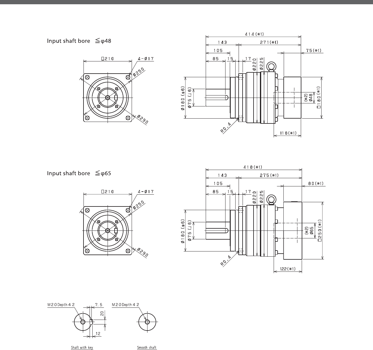
VRS-SERIES Inline shaft
VRS- 1-Stage Dimensions
*1) Length will vary depending on motor.
*2) Bushing will be inserted to adapt to motor shaft

VRS
VRS- 2-Stage Dimensions
*1) Length will vary depending on motor.
*2) Bushing will be inserted to adapt to motor shaft

VRS-SERIES Inline shaft
VRS- 1-Stage Adapter Dimensions
*1) Single reduction : /~ /
*2) Bushing will be inserted to adapt to motor shaft
Model number **: Adapter code 1-Stage
L1 L* L2 L3 L4 L5
VRS-210-□-□-38**
(Input shaft bore ≦ φ38)
HA -- -- -- -- -- --
HB•HE -- -- -- -- -- --
JA -- -- -- -- -- --
KA•KB•KC -- -- -- -- -- --
KD -- -- -- -- -- --
KE -- -- -- -- -- --
LA -- -- -- -- -- --
LB -- -- -- -- -- --
MA•MB -- -- -- -- -- --
MC -- -- -- -- -- --
MD -- -- -- -- -- --
NA -- -- -- -- -- --
VRS-210-□-□-48**
(Input shaft bore ≦ φ48)
KA 414 339 271 □180 75 118
KB•KC 394 339 251 □180 55 98
LA 394 339 251 □200 55 98
MA 394 339 251 □220 55 98
MB 414 339 271 □220 75 118
NA 414 339 271 □250 75 118
PA 414 339 271 □280 75 118
VRS-210-□-□-65**
(Input shaft bore ≦ φ65)
MA•MB•MC•MD 418 338 275 □220 80 122
NA•NC 418 338 275 □250 80 122
NB•ND 448 338 305 □250 110 152
PA 438 338 295 □280 100 142
PB 448 338 305 □280 110 152
QA•QB 438 338 295 □320 100 142
A more comprehensive adapter ange o ering can be found using the NIDECSHIMPO Online Selector Tool. The variety is constantly
expanding and being updated on the Selector Tool. If you have any questions or need any support, contact NIDECSHIMPO.
For an explanation on the Adapter Flange Code, please turn to page .

VRS
VRS- 2-Stage Adapter Dimensions
*1) Double reduction : /~ /
*2) Bushing will be inserted to adapt to motor shaft
Model number **: Adapter code 2-Stage
L1 L* L2 L3 L4 L5
VRS-210-□-□-38**
(Input shaft bore ≦ φ38)
HA 413 368 270 □130 45 82
HB•HE 408 368 265 □130 40 77
JA 413 368 270 □150 45 82
KA•KB•KC 413 368 270 □180 45 82
KD 448 368 305 □180 80 117
KE 428 368 285 □180 60 97
LA 413 368 270 □200 45 82
LB 423 368 280 □200 55 92
MA•MB 413 368 270 □220 45 82
MC 428 368 285 □220 60 97
MD 423 368 280 □220 55 92
NA 413 368 270 □250 45 82
VRS-210-□-□-48**
(Input shaft bore ≦ φ48)
KA 449 374 306 □180 75 118
KB•KC 429 374 286 □180 55 98
LA 429 374 286 □200 55 98
MA 429 374 286 □220 55 98
MB 449 374 306 □220 75 118
NA 449 374 306 □250 75 118
PA 449 374 306 □280 75 118
VRS-210-□-□-65**
(Input shaft bore ≦ φ65)
MA•MB•MC•MD -- -- -- -- -- --
NA•NC -- -- -- -- -- --
NB•ND -- -- -- -- -- --
PA -- -- -- -- -- --
PB -- -- -- -- -- --
QA•QB -- -- -- -- -- --
A more comprehensive adapter ange o ering can be found using the NIDECSHIMPO Online Selector Tool. The variety is constantly
expanding and being updated on the Selector Tool. If you have any questions or need any support, contact NIDECSHIMPO.
For an explanation on the Adapter Flange Code, please turn to page .

VRS-SERIES Inline shaft
VRS- 1-Stage Specifications
VRS- 2-Stage Specifications
Frame Size 240
Stage 1-Stage
Ratio Unit Note 3 4 5 6 7 8 9 10
Nominal Output Torque [Nm] *1 1600 2400 2400 2400 2400 2400 1600 1600
Maximum Acceleration Torque [Nm] *2 2500 3700 3700 3700 3700 3600 3000 2600
Emergency Stop Torque [Nm] *3 6000 8000 8000 8000 8000 8000 6000 6000
Nominal Input Speed [rpm] *4 1000
Maximum Input Speed [rpm] *5 2000
No Load Running Torque [Nm] *6 5.96
Permitted Radial Load [N] *7 21000 22000 24000 25000 26000 28000 29000 29000
Permitted Axial Load [N] *8 27000 27000 27000 27000 27000 27000 27000 27000
Maximum Radial Load [N] *9 30000
Maximum Axial Load [N] *10 27000
Moment of Inertia (≤Ø 48) [kgcm2] -- -- -- -- -- -- -- -- --
Moment of Inertia (≤ Ø 65) [kgcm2] -- 220.000 160.000 130.000 120.000 110.000 110.000 110.000 100.000
E ciency [%] *11 97
Torsional Rigidity [Nm/arc-min] *12 550
Maximum Torsional Backlash [arc-min] -- ≤ 3
Noise Level [dB] *13 62
Protection Class -- *14 IP54 (IP65)
Ambient Temperature [°C] -- 0-40
Permitted Housing Temperature [°C] -- 90
Weight [kg] *15 85
Frame Size 240
Stage 2-Stage
Ratio Unit Note 15 16 20 25 28 30 35 40
Nominal Output Torque [Nm] *1 1600 2400 2400 2400 2400 1600 2400 2400
Maximum Acceleration Torque [Nm] *2 2500 3700 3700 3700 3700 2500 3700 3700
Emergency Stop Torque [Nm] *3 6000 8000 8000 8000 8000 6000 8000 8000
Nominal Input Speed [rpm] *4 1000
Maximum Input Speed [rpm] *5 2000
No Load Running Torque [Nm] *6 1.28
Permitted Radial Load [N] *7 30000 30000 30000 30000 30000 30000 30000 30000
Permitted Axial Load [N] *8 27000 27000 27000 27000 27000 27000 27000 27000
Maximum Radial Load [N] *9 30000
Maximum Axial Load [N] *10 27000
Moment of Inertia (≤Ø 48) [kgcm2] -- 40.000 43.000 39.000 39.000 41.000 35.000 38.000 35.000
Moment of Inertia (≤ Ø 65) [kgcm2] -- -- -- -- -- -- -- -- --
E ciency [%] *11 92
Torsional Rigidity [Nm/arc-min] *12 550
Maximum Torsional Backlash [arc-min] -- ≤ 3
Noise Level [dB] *13 62
Protection Class -- *14 IP54 (IP65)
Ambient Temperature [°C] -- 0-40
Permitted Housing Temperature [°C] -- 90
Weight [kg] *15 89

VRS
VRS- 2-Stage Specifications
Frame Size 240
Stage 2-Stage
Ratio Unit Note 45 50 60 70 80 90 100
Nominal Output Torque [Nm] *1 1600 2400 2400 2400 2400 1600 1600
Maximum Acceleration Torque [Nm] *2 2100 3700 3700 3700 2700 2100 1800
Emergency Stop Torque [Nm] *3 6000 8000 8000 8000 8000 6000 6000
Nominal Input Speed [rpm] *4 1000
Maximum Input Speed [rpm] *5 2000
No Load Running Torque [Nm] *6 1.28
Permitted Radial Load [N] *7 30000 30000 30000 30000 30000 30000 30000
Permitted Axial Load [N] *8 27000 27000 27000 27000 27000 27000 27000
Maximum Radial Load [N] *9 30000
Maximum Axial Load [N] *10 27000
Moment of Inertia (≤Ø 48) [kgcm2] -- 38.000 35.000 35.000 34.000 34.000 34.000 34.000
Moment of Inertia (≤ Ø 65) [kgcm2] -- -- -- -- -- -- -- --
E ciency [%] *11 92
Torsional Rigidity [Nm/arc-min] *12 550
Maximum Torsional Backlash [arc-min] -- ≤ 3
Noise Level [dB] *13 62
Protection Class -- *14 IP54 (IP65)
Ambient Temperature [°C] -- 0-40
Permitted Housing Temperature [°C] -- 90
Weight [kg] *15 89
*1) At nominal input speed, service life is , hours
*2) The maximum torque when starting or stopping operation
*3) The maximum torque allowed under a stress situation (Permitted , times during service life)
*4) The average input speed
*5) The maximum intermittent input speed
*6) This is the torque at no load applied on the input shaft. The input speed is , rpm for VRS
*7) At this load and nominal input speed, service life will be , hours. (The radial load applied to the output side bearing)
*8) At this load and nominal input speed, service life will be , hours. (The axial load applied to the output shaft center)
*9) The maximum radial load that the reducer can accept
*10) The maximum axial load that the reducer can accept
*11) The e ciency at the nominal torque rating
*12) This does not include the lost motion
*13) Contact NIDEC-SHIMPO for the testing conditions and environment
*14) IP (wash-down) is available as an option. Contact NIDECSHIMPO for more details and our food grade options
*15) The weight may vary slightly between models

VRS-SERIES Inline shaft
VRS- 1-Stage Dimensions
*1) Length will vary depending on motor
*2) Bushing will be inserted to adapt to motor shaft

VRS
VRS- 2-Stage Dimensions
*1) Length will vary depending on motor
*2) Bushing will be inserted to adapt to motor shaft

VRS-SERIES Inline shaft
VRS- 1-Stage Adapter Dimensions
*1) Single reduction : /~ /
*2) Bushing will be inserted to adapt to motor shaft
Model number **: Adapter code 1-Stage
L1 L* L2 L3 L4 L5
VRS-240-□-□-48**
(Input shaft bore ≦ φ48)
KA -- -- -- -- -- --
KB•KC -- -- -- -- -- --
LA -- -- -- -- -- --
MA -- -- -- -- -- --
MB -- -- -- -- -- --
NA -- -- -- -- -- --
PA -- -- -- -- -- --
VRS-240-□-□-65**
(Input shaft bore ≦ φ65)
MA•MB•MC•MD 465.5 385.5 295.5 □220 80 122
NA•NC 465.5 385.5 295.5 □250 80 122
NB•ND 495.5 385.5 325.5 □250 110 152
PA 485.5 385.5 315.5 □280 100 142
PB 495.5 385.5 325.5 □280 110 152
QA•QB 485.5 385.5 315.5 □320 100 142
A more comprehensive adapter ange o ering can be found using the NIDECSHIMPO Online Selector Tool. The variety is constantly
expanding and being updated on the Selector Tool. If you have any questions or need any support, contact NIDECSHIMPO.
For an explanation on the Adapter Flange Code, please turn to page .

VRS
VRS- 2-Stage Adapter Dimensions
*1) Double reduction : /~ /
*2) Bushing will be inserted to adapt to motor shaft
Model number **: Adapter code 2-Stage
L1 L* L2 L3 L4 L5
VRS-240-□-□-48**
(Input shaft bore ≦ φ48)
KA 516 441 346 □180 75 118
KB•KC 496 441 326 □180 55 98
LA 496 441 326 □200 55 98
MA 496 441 326 □220 55 98
MB 516 441 346 □220 75 118
NA 516 441 346 □250 75 118
PA 516 441 346 □280 75 118
VRS-240-□-□-65**
(Input shaft bore ≦ φ65)
MA•MB•MC•MD -- -- -- -- -- --
NA•NC -- -- -- -- -- --
NB•ND -- -- -- -- -- --
PA -- -- -- -- -- --
PB -- -- -- -- -- --
QA•QB -- -- -- -- -- --
A more comprehensive adapter ange o ering can be found using the NIDECSHIMPO Online Selector Tool. The variety is constantly
expanding and being updated on the Selector Tool. If you have any questions or need any support, contact NIDECSHIMPO.
For an explanation on the Adapter Flange Code, please turn to page .

The VRT series sets the new standard in applications requiring
extremely high-torque ratings and rigidity. The compact design
and hub-style output is ideal for equipment requiring high speed,
high precision indexing movement. The remarkable torsional stiff-
ness and the low backlash of the planetary gearing combine to pro-
vide outstanding positioning accuracy.
With a backlash rating less than arc-minutes and exceptional torque
handling capabilities, the VRT o ers a high performance robust plane-
tary solution for OEM customers. The VRT reducer is often used for larger
indexing applications and dial tables commonly found in packaging
and lling equipment and assembly automation systems.
VRT-SERIES

VRT-SERIES
■ISO robotics industry mounting interface
■Superior exibility in mounting of pinions, pulleys and turntables
■Exceptional torsional rigidity for high positional accuracy needs
■Nice compact and robust design
■Impressive radial and axial load capability
VRT

VRT-SERIES Inline shaft
VRT-Series Features
1 High precision: Standard backlash is arc-min, ideal for higher levels of positional accuracy
2 High rigidity & torque: Rigidity and torque capacity are achieved by using uncaged needle roller bearings
3 High load capacity: Tapered roller bearings were added to the output section to increase radial and axial
load ratings on most frame sizes
4 Adapter-bushing connection: Enables a simple, e ective attachment to most servo motors
5 No leakage through the seal: High viscosity, anti-separation grease does not liquefy and does not migrate
away from the gears
6 Maintenance-free: No need to replace the grease for the life of the unit. The reducer can be positioned in
any orientation
2
1
3
4
5
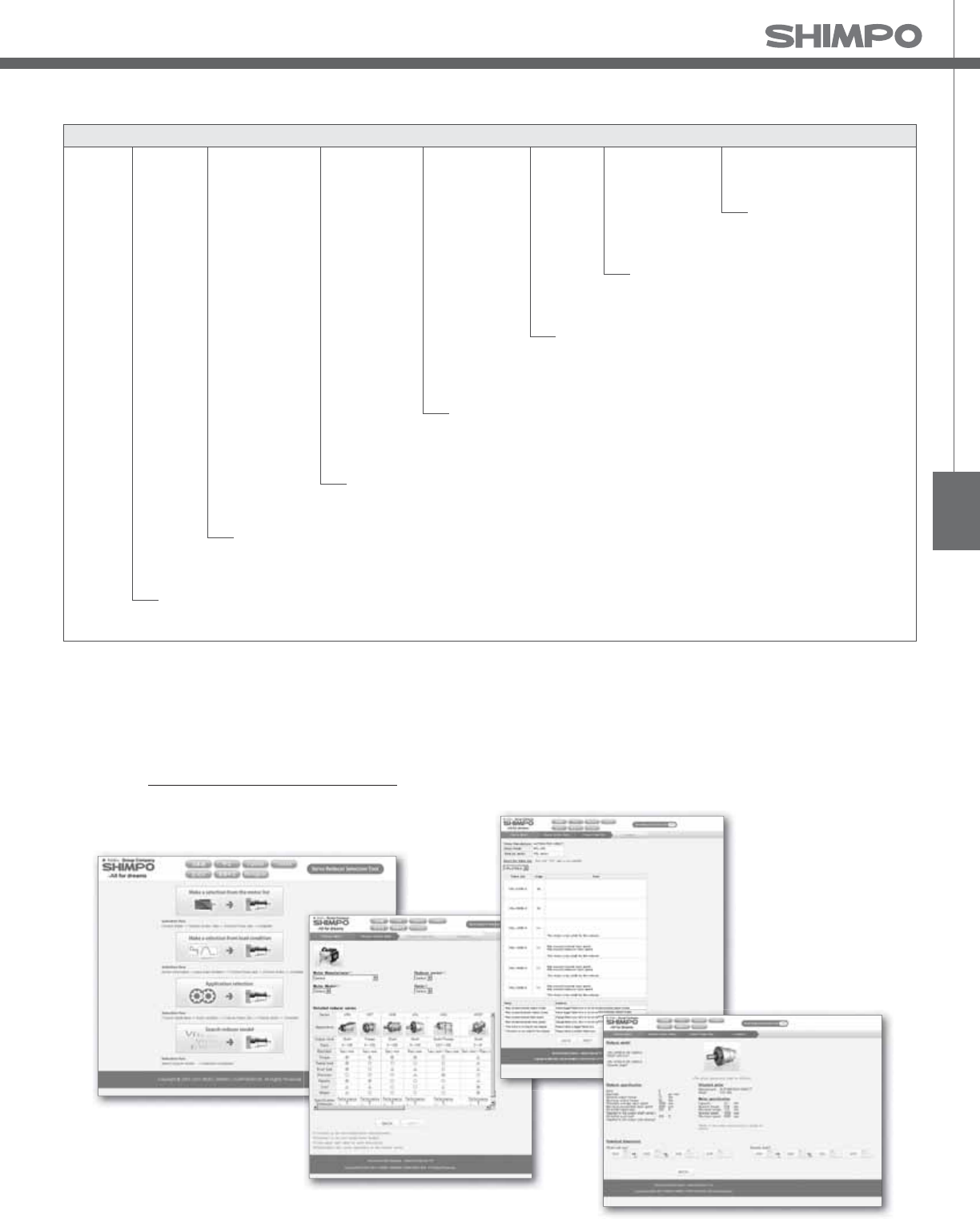
VRT
VRT-Series Model Code
㩷Adapter ange code
VR
T 090− − 7 F 3 19HB16−−
Backlash 㪊㪸㫉㪺㪄㫄㫀㫅㪊䊶䊶䊶
Output style F・・・ Flange output
Ratio Single: 4, 5, 7, 10
Double: 16, 20, 25, 28, 35, 40, 50, 70, 100
Frame size:
Model name for ABLE reducer
Series name VRT Series
047, 064, 090, *110B, *140B, *200B, *255B, *285B
*1) Adapter ange code
Adapter ange code varies depending on the motor.
* Frames > 090 are a di erent generation of design, include letter B with frame size
Contact us for additional information or refer to our online reducer selection tool.
Selection tool www.nidec-shimpo.co.jp/selection/eng

VRT-SERIES Inline shaft
Frame Size 047
Stage 1-Stage
Ratio Unit Notes 4 5 6 7 8 9 10
Nominal Output Torque [Nm] *1 9 9 9 9 9 6 6
Maximum Acceleration Torque [Nm] *2 18 18 18 18 18 12 12
Emergency Stop Torque [Nm] *3 35 35 35 35 35 30 30
Nominal Input Speed [rpm] *4 4000
Maximum Input Speed [rpm] *5 8000
No Load Running Torque [Nm] *6 0.03
Permitted Radial Load [N] *7 270 300 310 330 350 360 370
Permitted Axial Load [N] *8 300 330 360 390 410 430 450
Maximum Radial Load [N] *9 1100
Maximum Axial Load [N] *10 550
Moment of Inertia (≤ Ø 8) [kgcm2] -- 0.052 0.043 0.038 0.036 0.034 0.033 0.032
Moment of Inertia (≤ Ø 14) [kgcm2] -- 0.090 0.081 0.077 0.074 0.072 0.071 0.071
E ciency [%] *11 95
Torsional Rigidity [Nm/arc-min] *12 2
Maximum Torsional Backlash [arc-min] -- ≤ 3
Noise Level [dB] *13 ≤ 61
Protection Class -- *14 IP54 (IP65)
Ambient Temperature [°C] -- 0 - 40
Permitted Housing Temperature [°C] -- 90
Weight [kg] *15 0.7
Frame Size 047
Stage 2-Stage
Ratio Unit Notes 16 20 25 28 35 40 45
Nominal Output Torque [Nm] *1 9 9 9 9 9 9 6
Maximum Acceleration Torque [Nm] *2 18 18 18 18 18 18 12
Emergency Stop Torque [Nm] *3 35 35 35 35 35 35 30
Nominal Input Speed [rpm] *4 4000
Maximum Input Speed [rpm] *5 8000
No Load Running Torque [Nm] *6 0.01
Permitted Radial Load [N] *7 440 470 510 530 570 590 620
Permitted Axial Load [N] *8 550 550 550 550 550 550 550
Maximum Radial Load [N] *9 1100
Maximum Axial Load [N] *10 550
Moment of Inertia (≤ Ø 8) [kgcm2] -- 0.039 0.035 0.034 0.038 0.034 0.030 0.034
Moment of Inertia (≤ Ø 14) [kgcm2] -- -- -- -- -- -- -- --
E ciency [%] *11 90
Torsional Rigidity [Nm/arc-min] *12 2
Maximum Torsional Backlash [arc-min] -- ≤ 5
Noise Level [dB] *13 ≤ 61
Protection Class -- *14 IP54 (IP65)
Ambient Temperature [°C] -- 0 - 40
Permitted Housing Temperature [°C] -- 90
Weight [kg] *15 0.8
VRT- 1-Stage Specifications
VRT- 2-Stage Specifications

VRT
Frame Size 047
Stage 2-Stage
Ratio Unit Notes 50 60 70 80 90 100
Nominal Output Torque [Nm] *1 9 9 9 9 6 6
Maximum Acceleration Torque [Nm] *2 18 18 18 18 12 12
Emergency Stop Torque [Nm] *3 35 35 35 35 30 30
Nominal Input Speed [rpm] *4 4000
Maximum Input Speed [rpm] *5 8000
No Load Running Torque [Nm] *6 0.01
Permitted Radial Load [N] *7 640 680 710 750 780 800
Permitted Axial Load [N] *8 550 550 550 550 550 550
Maximum Radial Load [N] *9 1100
Maximum Axial Load [N] *10 550
Moment of Inertia (≤ Ø 8) [kgcm2] -- 0.030 0.030 0.030 0.030 0.030 0.030
Moment of Inertia (≤ Ø 14) [kgcm2] -- -- -- -- -- -- --
E ciency [%] *11 90
Torsional Rigidity [Nm/arc-min] *12 2
Maximum Torsional Backlash [arc-min] -- ≤ 5
Noise Level [dB] *13 ≤ 61
Protection Class -- *14 IP54 (IP65)
Ambient Temperature [°C] -- 0 - 40
Permitted Housing Temperature [°C] -- 90
Weight [kg] *15 0.8
VRT- 2-Stage Specifications
*1) At nominal input speed, service life is , hours
*2) The maximum torque when starting or stopping operation
*3) The maximum torque allowed under a stress situation (Permitted , times during service life)
*4) The average input speed
*5) The maximum intermittent input speed
*6) This is the torque at no load applied on the input shaft. The input speed is , rpm for VRT
*7) At this load and nominal input speed, service life will be , hours. (The radial load applied to the output side bearing)
*8) At this load and nominal input speed, service life will be , hours. (The axial load applied to the output ange center)
*9) The maximum radial load that the reducer can accept
*10) The maximum axial load that the reducer can accept
*11) The e ciency at the nominal torque rating
*12) This does not include the lost motion
*13) Contact NIDEC-SHIMPO for the testing conditions and environment
*14) IP (wash-down) is available as an option. Contact NIDECSHIMPO for more details and our food grade options
*15) The weight may vary slightly between models
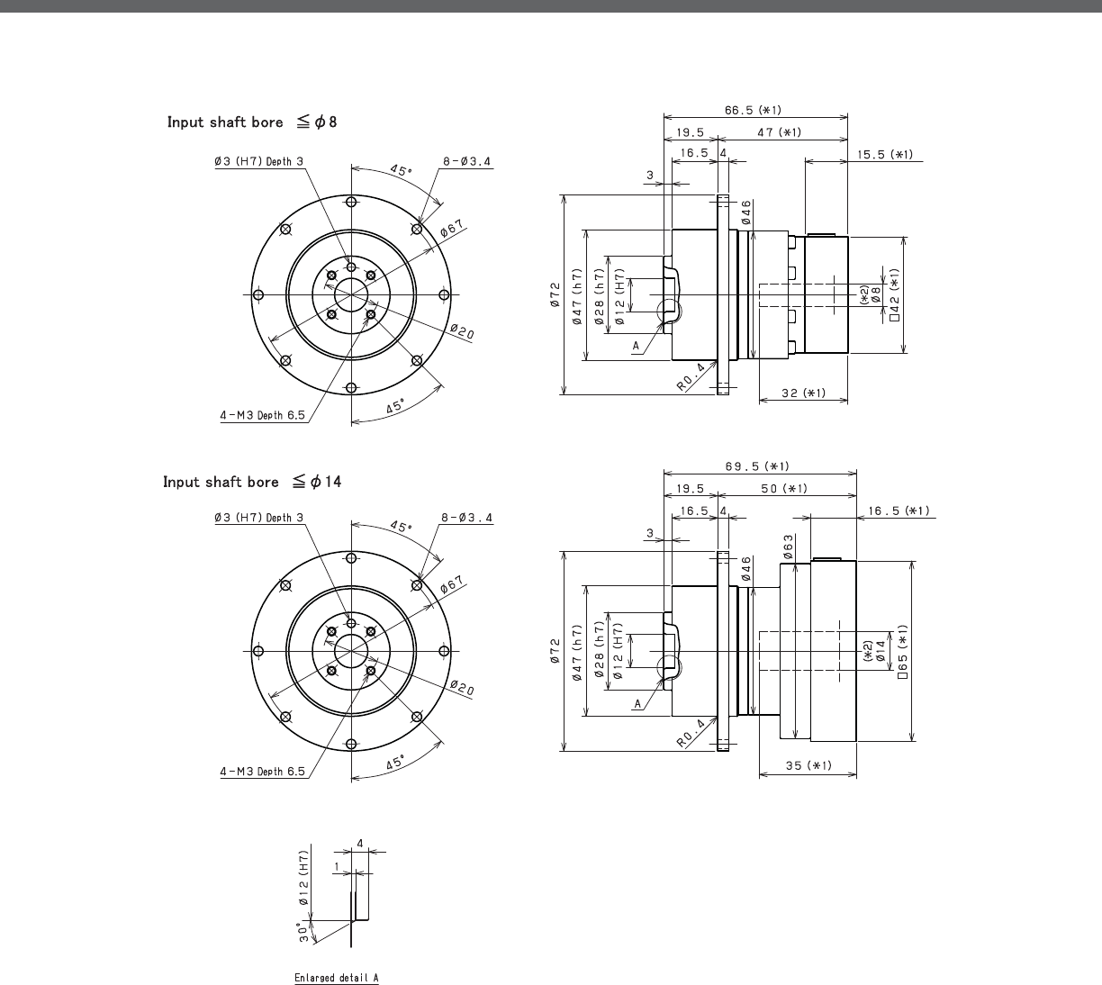
VRT-SERIES Inline shaft
VRT- 1-Stage Dimensions
*1) Length will vary depending on motor
*2) Bushing will be inserted to adapt to motor shaft
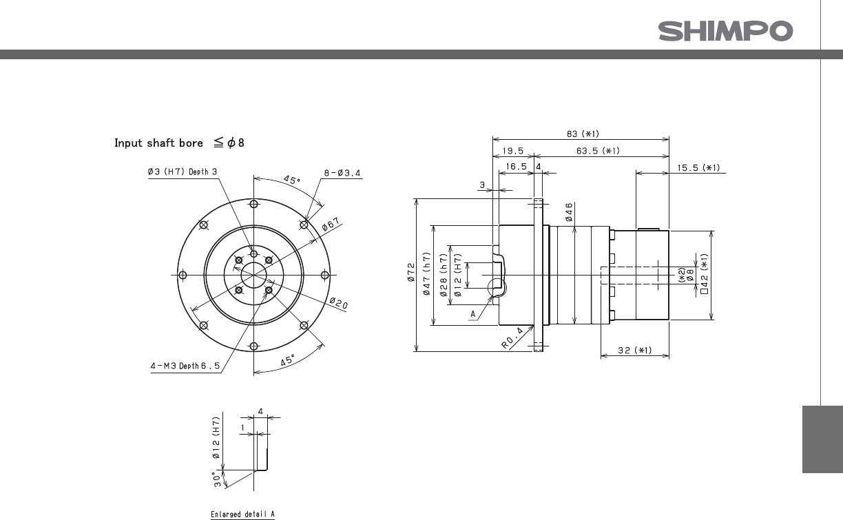
VRT
VRT- 2-Stage Dimensions
*1) Length will vary depending on motor
*2) Bushing will be inserted to adapt to motor shaft

VRT-SERIES Inline shaft
VRT- 1-Stage Adapter Dimensions
Model Number **: Adapter Code 1-Stage
L1 L* L2 L3 L4 L5
VRT-047-□-□-S8**
(Input shaft bore ≦ φ8)
AA•AC•AD•AF•AG 66.5 51 47 □42 15.5 32
AB•AE•AH•AJ•AK 71.5 51 52 □42 20.5 37
BC•BF 66.5 51 47 □60 15.5 32
CA 71.5 51 52 □60 20.5 37
VRT-047-□-□-14**
(Input shaft bore ≦ φ14)
BA•BB•BD•BE•BF•BG•BJ•BK•BP 69.5 53 50 □65 16.5 35
BC•BH•BM•BN 74.5 53 55 □65 21.5 40
BL 79.5 53 60 □65 26.5 45
*1) Single reduction : / - /
*2) Bushing will be inserted to adapt to motor shaft
A more comprehensive adapter ange o ering can be found using the NIDECSHIMPO Online Selector Tool. The variety is constantly
expanding and being updated on the Selector Tool. If you have any questions or need any support, contact NIDECSHIMPO.
For an explanation on the Adapter Flange Code, please turn to page .

VRT
VRT- 2-Stage Adapter Dimensions
Model Number **: Adapter Code 2-Stage
L1 L* L2 L3 L4 L5
VRT-047-□-□-S8**
(Input shaft bore ≦ φ8)
AA•AC•AD•AF•AG 83 67.5 63.5 □42 15.5 32
AB•AE•AH•AJ•AK 88 67.5 68.5 □42 20.5 37
BC•BF 83 67.5 63.5 □60 15.5 32
CA 88 67.5 68.5 □60 20.5 37
VRT-047-□-□-14**
(Input shaft bore ≦ φ14)
BA•BB•BD•BE•BF•BG•BJ•BK•BP -- -- -- -- -- --
BC•BH•BM•BN -- -- -- -- -- --
BL -- -- -- -- -- --
*1) Double reduction : / - /
*2) Bushing will be inserted to adapt to motor shaft
A more comprehensive adapter ange o ering can be found using the NIDECSHIMPO Online Selector Tool. The variety is constantly
expanding and being updated on the Selector Tool. If you have any questions or need any support, contact NIDECSHIMPO.
For an explanation on the Adapter Flange Code, please turn to page .

VRT-SERIES Inline shaft
VRT- 1-Stage Specifications
Frame Size 064
Stage 1-Stage
Ratio Unit Note 4 5 6 7 8 9 10
Nominal Output Torque [Nm] *1 27 27 27 27 27 18 18
Maximum Acceleration Torque [Nm] *2 50 50 50 50 50 35 35
Emergency Stop Torque [Nm] *3 100 100 100 100 100 80 80
Nominal Input Speed [rpm] *4 3000
Maximum Input Speed [rpm] *5 6000
No Load Running Torque [Nm] *6 0.08
Permitted Radial Load [N] *7 370 400 420 440 460 480 500
Permitted Axial Load [N] *8 360 390 430 460 480 510 530
Maximum Radial Load [N] *9 1500
Maximum Axial Load [N] *10 750
Moment of Inertia (≤ Ø 8) [kgcm2] -- 0.130 0.100 0.085 0.075 0.068 0.064 0.062
Moment of Inertia (≤ Ø 14) [kgcm2] -- 0.210 0.180 0.170 0.150 0.150 0.140 0.140
Moment of Inertia (≤ Ø 19) [kgcm2] -- 0.400 0.400 0.400 0.400 0.400 0.400 0.400
E ciency [%] *11 95
Torsional Rigidity [Nm/arc-min] *12 3
Maximum Torsional Backlash [arc-min] -- ≤ 3
Noise Level [dB] *13 ≤ 66
Protection Class -- *14 IP54 (IP65)
Ambient Temperature [°C] -- 0 - 40
Permitted Housing Temperature [°C] -- 90
Weight [kg] *15 1.4
Frame Size 064
Stage 2-Stage
Ratio Unit Note 16 20 25 28 35 40 45
Nominal Output Torque [Nm] *1 27 27 27 27 27 27 18
Maximum Acceleration Torque [Nm] *2 50 50 50 50 50 50 35
Emergency Stop Torque [Nm] *3 100 100 100 100 100 100 80
Nominal Input Speed [rpm] *4 3000
Maximum Input Speed [rpm] *5 6000
No Load Running Torque [Nm] *6 0.04
Permitted Radial Load [N] *7 580 630 680 700 760 790 820
Permitted Axial Load [N] *8 650 720 750 750 750 750 750
Maximum Radial Load [N] *9 1500
Maximum Axial Load [N] *10 750
Moment of Inertia (≤ Ø 8) [kgcm2] -- 0.059 0.055 0.054 0.056 0.053 0.049 0.530
Moment of Inertia (≤ Ø 14) [kgcm2] -- 0.140 0.140 0.130 0.140 0.130 0.130 0.130
Moment of Inertia (≤ Ø 19) [kgcm2] -- 0.360 0.350 0.350 0.360 0.350 0.340 0.350
E ciency [%] *11 90
Torsional Rigidity [Nm/arc-min] *12 3
Maximum Torsional Backlash [arc-min] -- ≤ 3
Noise Level [dB] *13 ≤ 66
Protection Class -- *14 IP54 (IP65)
Ambient Temperature [°C] -- 0 - 40
Permitted Housing Temperature [°C] -- 90
Weight [kg] *15 1.6
VRT- 2-Stage Specifications

VRT
VRT- 2-Stage Specifications
Frame Size 064
Stage 2-Stage
Ratio Unit Note 50 60 70 80 90 100
Nominal Output Torque [Nm] *1 27 27 27 27 18 18
Maximum Acceleration Torque [Nm] *2 50 50 50 50 35 35
Emergency Stop Torque [Nm] *3 100 100 100 100 80 80
Nominal Input Speed [rpm] *4 3000
Maximum Input Speed [rpm] *5 6000
No Load Running Torque [Nm] *6 0.04
Permitted Radial Load [N] *7 850 910 950 1000 1000 1100
Permitted Axial Load [N] *8 750 750 750 750 750 750
Maximum Radial Load [N] *9 1500
Maximum Axial Load [N] *10 750
Moment of Inertia (≤ Ø 8) [kgcm2] -- 0.049 0.049 0.049 0.049 0.049 0.049
Moment of Inertia (≤ Ø 14) [kgcm2] -- 0.130 0.130 0.130 0.130 0.130 0.130
Moment of Inertia (≤ Ø 19) [kgcm2] -- 0.340 0.340 0.340 0.340 0.340 0.340
E ciency [%] *11 90
Torsional Rigidity [Nm/arc-min] *12 3
Maximum Torsional Backlash [arc-min] -- ≤ 3
Noise Level [dB] *13 ≤ 66
Protection Class -- *14 IP54 (IP65)
Ambient Temperature [°C] -- 0 - 40
Permitted Housing Temperature [°C] -- 90
Weight [kg] *15 1.6
*1) At nominal input speed, service life is , hours
*2) The maximum torque when starting or stopping operation
*3) The maximum torque allowed under a stress situation (Permitted , times during service life)
*4) The average input speed
*5) The maximum intermittent input speed
*6) This is the torque at no load applied on the input shaft. The input speed is , rpm for VRT
*7) At this load and nominal input speed, service life will be , hours. (The radial load applied to the output side bearing)
*8) At this load and nominal input speed, service life will be , hours. (The axial load applied to the output ange center)
*9) The maximum radial load that the reducer can accept
*10) The maximum axial load that the reducer can accept
*11) The e ciency at the nominal torque rating
*12) This does not include the lost motion
*13) Contact NIDEC-SHIMPO for the testing conditions and environment
*14) IP (wash-down) is available as an option. Contact NIDECSHIMPO for more details and our food grade options
*15) The weight may vary slightly between models

VRT-SERIES Inline shaft
VRT- 1-Stage Dimensions
*1) Length will vary depending on motor
*2) Bushing will be inserted to adapt to motor shaft

VRT
VRT- 2-Stage Dimensions
*1) Length will vary depending on motor
*2) Bushing will be inserted to adapt to motor shaft

VRT-SERIES Inline shaft
VRT- 1-Stage Adapter Dimensions
*1) Single reduction : / - /
*2) Bushing will be inserted to adapt to motor shaft
Model Number **: Adapter Code 1-Stage
L1 L* L2 L3 L4 L5
VRT-064-□-□-8**
(Input shaft bore ≦ φ8)
AA•AC•AD•AF•AG•AL•AM•AN•AQ 79 63.5 59.5 □52 15.5 32
AB•AE•AH•AJ•AK 84 63.5 64.5 □52 20.5 37
BA•BB•BD•BE•BG•BH•BJ 79 63.5 59.5 □60 15.5 32
BC•BF 84 63.5 64.5 □60 20.5 37
CA 84 63.5 64.5 □70 20.5 37
VRT-064-□-□-14**
(Input shaft bore ≦ φ14)
BA•BB•BD•BE•BF•BG•BH•BJ•BK•BP 82 65.5 62.5 □65 16.5 35
BC•BH•BM•BN 87 65.5 67.5 □65 21.5 40
BL 92 65.5 72.5 □65 26.5 45
CA•CC 82 65.5 62.5 □70 16.5 35
CB 87 65.5 67.5 □70 21.5 40
DA•DB•DC•DD•DF•DH•DJ 82 65.5 62.5 □80 16.5 35
DE•DL 87 65.5 67.5 □80 21.5 40
DG•DK 92 65.5 72.5 □80 26.5 45
EA•EB•EC•EF•EG•EK•EL 82 65.5 62.5 □90 16.5 35
EJ•EM 87 65.5 67.5 □90 21.5 40
ED•EE•EH 92 65.5 72.5 □90 26.5 45
FA 82 65.5 62.5 □100 16.5 35
FB 82 65.5 62.5 □115 16.5 35
VRT-064-□-□-19**
(Input shaft bore ≦ φ19)
DA•DB•DC 97 72 77.5 □80 25 50
DD 107 72 87.5 □80 35 60
DE 102 72 82.5 □80 30 55
EA 102 72 82.5 □90 30 55
EB•ED 97 72 77.5 □90 25 50
EC 107 72 87.5 □90 35 60
FA 97 72 77.5 □100 25 50
FB 107 72 87.5 □100 35 60
A more comprehensive adapter ange o ering can be found using the NIDECSHIMPO Online Selector Tool. The variety is constantly
expanding and being updated on the Selector Tool. If you have any questions or need any support, contact NIDECSHIMPO.
For an explanation on the Adapter Flange Code, please turn to page .

VRT
VRT- 2-Stage Adapter Dimensions
*1) Double reduction : / - /
*2) Bushing will be inserted to adapt to motor shaft
Model Number **: Adapter Code 2-Stage
L1 L* L2 L3 L4 L5
VRT-064-□-□-8**
(Input shaft bore ≦ φ8)
AA•AC•AD•AF•AG•AL•AM•AN•AQ 98 82.5 78.5 □52 15.5 32
AB•AE•AH•AJ•AK 103 82.5 83.5 □52 20.5 37
BA•BB•BD•BE•BG•BH•BJ 98 82.5 78.5 □60 15.5 32
BC•BF 103 82.5 83.5 □60 20.5 37
CA 103 82.5 83.5 □70 20.5 37
VRT-064-□-□-14**
(Input shaft bore ≦ φ14)
BA•BB•BD•BE•BF•BG•BH•BJ•BK•BP 103 86.5 83.5 □65 16.5 35
BC•BH•BM•BN 108 86.5 88.5 □65 21.5 40
BL 113 86.5 93.5 □65 26.5 45
CA•CC 103 86.5 83.5 □70 16.5 35
CB 108 86.5 88.5 □70 21.5 40
DA•DB•DC•DD•DF•DH•DJ 103 86.5 83.5 □80 16.5 35
DE•DL 108 86.5 88.5 □80 21.5 40
DG•DK 113 86.5 93.5 □80 26.5 45
EA•EB•EC•EF•EG•EK•EL 103 86.5 83.5 □90 16.5 35
EJ•EM 108 86.5 88.5 □90 21.5 40
ED•EE•EH 113 86.5 93.5 □90 26.5 45
FA 103 86.5 83.5 □100 16.5 35
FB 103 86.5 83.5 □115 16.5 35
VRT-064-□-□-19**
(Input shaft bore ≦ φ19)
DA•DB•DC 118 93 98.5 □80 25 50
DD 128 93 108.5 □80 35 60
DE 123 93 103.5 □80 30 55
EA 123 93 103.5 □90 30 55
EB•ED 118 93 98.5 □90 25 50
EC 128 93 108.5 □90 35 60
FA 118 93 98.5 □100 25 50
FB 128 93 108.5 □100 35 60
A more comprehensive adapter ange o ering can be found using the NIDECSHIMPO Online Selector Tool. The variety is constantly
expanding and being updated on the Selector Tool. If you have any questions or need any support, contact NIDECSHIMPO.
For an explanation on the Adapter Flange Code, please turn to page .

VRT-SERIES Inline shaft
VRT- 1-Stage Specifications
VRT- 2-Stage Specifications
Frame Size 090
Stage 1-Stage
Ratio Unit Note 4 5 6 7 8 9 10
Nominal Output Torque [Nm] *1 75 75 75 75 75 50 50
Maximum Acceleration Torque [Nm] *2 125 125 125 125 125 80 80
Emergency Stop Torque [Nm] *3 250 250 250 250 250 200 200
Nominal Input Speed [rpm] *4 3000
Maximum Input Speed [rpm] *5 6000
No Load Running Torque [Nm] *6 0.17
Permitted Radial Load [N] *7 720 780 830 870 910 950 980
Permitted Axial Load [N] *8 620 680 740 790 830 880 920
Maximum Radial Load [N] *9 3300
Maximum Axial Load [N] *10 1700
Moment of Inertia (≤ Ø 8) [kgcm2] -- - - - - - - -
Moment of Inertia (≤ Ø 14) [kgcm2] -- 0.770 0.580 0.480 0.410 0.370 0.350 0.330
Moment of Inertia (≤ Ø 19) [kgcm2] -- 1.200 1.000 0.940 0.880 0.840 0.810 0.800
Moment of Inertia (≤ Ø 28) [kgcm2] -- 2.900 2.900 2.800 2.800 2.800 2.800 2.800
E ciency [%] *11 95
Torsional Rigidity [Nm/arc-min] *12 10
Maximum Torsional Backlash [arc-min] -- ≤ 3
Noise Level [dB] *13 ≤ 67
Protection Class -- *14 IP54 (IP65)
Ambient Temperature [°C] -- 0 - 40
Permitted Housing Temperature [°C] -- 90
Weight [kg] *15 3.6
Frame Size 090
Stage 2-Stage
Ratio Unit Note 16 20 25 28 35 40
Nominal Output Torque [Nm] *1 75 75 75 75 75 75
Maximum Acceleration Torque [Nm] *2 125 125 125 125 125 125
Emergency Stop Torque [Nm] *3 250 250 250 250 250 250
Nominal Input Speed [rpm] *4 3000
Maximum Input Speed [rpm] *5 6000
No Load Running Torque [Nm] *6 0.05
Permitted Radial Load [N] *7 1200 1200 1300 1400 1500 1600
Permitted Axial Load [N] *8 1100 1200 1400 1400 1600 1700
Maximum Radial Load [N] *9 3300
Maximum Axial Load [N] *10 1700
Moment of Inertia (≤ Ø 8) [kgcm2] -- 0.160 0.140 0.130 0.140 0.130 0.100
Moment of Inertia (≤ Ø 14) [kgcm2] -- 0.310 0.290 0.280 0.300 0.280 0.250
Moment of Inertia (≤ Ø 19) [kgcm2] -- 0.750 0.730 0.720 0.730 0.720 0.700
Moment of Inertia (≤ Ø 28) [kgcm2] -- 2.800 2.700 2.700 2.800 2.700 2.600
E ciency [%] *11 90
Torsional Rigidity [Nm/arc-min] *12 10
Maximum Torsional Backlash [arc-min] -- ≤ 3
Noise Level [dB] *13 ≤ 67
Protection Class -- *14 IP54 (IP65)
Ambient Temperature [°C] -- 0 - 40
Permitted Housing Temperature [°C] -- 90
Weight [kg] *15 4

VRT
VRT- 2-Stage Specifications
Frame Size 090
Stage 2-Stage
Ratio Unit Note 45 50 60 70 80 90 100
Nominal Output Torque [Nm] *1 50 75 75 75 75 50 50
Maximum Acceleration Torque [Nm] *2 80 125 125 125 125 80 80
Emergency Stop Torque [Nm] *3 200 250 250 250 250 200 200
Nominal Input Speed [rpm] *4 3000
Maximum Input Speed [rpm] *5 6000
No Load Running Torque [Nm] *6 0.05
Permitted Radial Load [N] *7 1600 1700 1800 1900 2000 2000 2100
Permitted Axial Load [N] *8 1700 1700 1700 1700 1700 1700 1700
Maximum Radial Load [N] *9 3300
Maximum Axial Load [N] *10 1700
Moment of Inertia (≤ Ø 8) [kgcm2] -- 0.120 0.100 0.099 0.098 0.098 0.098 0.098
Moment of Inertia (≤ Ø 14) [kgcm2] -- 0.270 0.250 0.250 0.250 0.250 0.250 0.250
Moment of Inertia (≤ Ø 19) [kgcm2] -- 0.710 0.700 0.700 0.690 0.690 0.690 0.690
Moment of Inertia (≤ Ø 28) [kgcm2] -- 2.700 2.600 2.600 2.600 2.600 2.600 2.600
E ciency [%] *11 90
Torsional Rigidity [Nm/arc-min] *12 10
Maximum Torsional Backlash [arc-min] -- ≤ 3
Noise Level [dB] *13 ≤ 67
Protection Class -- *14 IP54 (IP65)
Ambient Temperature [°C] -- 0 - 40
Permitted Housing Temperature [°C] -- 90
Weight [kg] *15 4
*1) At nominal input speed, service life is , hours
*2) The maximum torque when starting or stopping operation
*3) The maximum torque allowed under a stress situation (Permitted , times during service life)
*4) The average input speed
*5) The maximum intermittent input speed
*6) This is the torque at no load applied on the input shaft. The input speed is , rpm for VRT
*7) At this load and nominal input speed, service life will be , hours. (The radial load applied to the output side bearing)
*8) At this load and nominal input speed, service life will be , hours. (The axial load applied to the output ange center)
*9) The maximum radial load that the reducer can accept
*10) The maximum axial load that the reducer can accept
*11) The e ciency at the nominal torque rating
*12) This does not include the lost motion
*13) Contact NIDEC-SHIMPO for the testing conditions and environment
*14) IP (wash-down) is available as an option. Contact NIDECSHIMPO for more details and our food grade options
*15) The weight may vary slightly between models

VRT-SERIES Inline shaft
VRT- 1-Stage Dimensions
*1) Length will vary depending on motor
*2) Bushing will be inserted to adapt to motor shaft

VRT
VRT- 2-Stage Dimensions
*1) Length will vary depending on motor
*2) Bushing will be inserted to adapt to motor shaft

VRT-SERIES Inline shaft
VRT- 1-Stage Adapter Dimensions
*1) Single reduction : /~ /
Model Number **: Adapter Code 1-Stage
L1 L* L2 L3 L4 L5
VRT-090-□-□-8**
(Input shaft bore ≦ φ8)
AA•AC•AD•AF•AG•AL•AM•AN•AQ -- -- -- -- -- --
AB•AE•AH•AJ•AK -- -- -- -- -- --
BA•BB•BD•BE•BG•BH•BJ -- -- -- -- -- --
CA -- -- -- -- -- --
VRT-090-□-□-14**
(Input shaft bore ≦ φ14)
BA•BB•BD•BE•BF•BG•BH•BJ•BK•BP 100 83.5 70 □65 16.5 35
BC•BH•BM•BN 105 83.5 75 □65 21.5 40
CA•CC 100 83.5 70 □70 16.5 35
DA•DB•DC•DD•DF•DH•DJ 100 83.5 70 □80 16.5 35
EA•EB•EC•EF•EG•EK•EL 100 83.5 70 □90 16.5 35
FA 100 83.5 70 □100 16.5 35
FB 110 83.5 80 □100 26.5 45
JA 115 83.5 85 □150 31.5 50
VRT-090-□-□-19**
(Input shaft bore ≦ φ19)
DA•DB•DC 110 85 80 □80 25 50
EB•ED 110 85 80 □90 25 50
FA 110 85 80 □100 25 50
FB 120 85 90 □100 35 60
GA•GC•GH 115 85 85 □115 30 55
GB•GD•GJ 110 85 80 □115 25 50
GE•GF 120 85 90 □115 35 60
HA 110 85 80 □130 25 50
HB 125 85 95 □130 40 65
HC•HD•HE 115 85 85 □130 30 55
JA 120 85 90 □150 35 60
JB 125 85 95 □150 40 65
VRT-090-□-□-28**
(Input shaft bore ≦ φ28)
FA•FB•FC 127 92 97 □100 35 67
FD•FE 122 92 92 □100 30 62
GA•GB•GC•GD•GE•GF•GG•GH 127 92 97 □115 35 67
HA•HC•HD 127 92 97 □130 35 67
HB 137 92 107 □130 45 77
HE 142 92 112 □130 50 82
HF 122 92 92 □130 30 62
JA•JB•JC•JF 127 92 97 □150 35 67
JD 147 92 117 □150 55 87
JE 137 92 107 □150 45 77
A more comprehensive adapter ange o ering can be found using the NIDECSHIMPO Online Selector Tool. The variety is constantly
expanding and being updated on the Selector Tool. If you have any questions or need any support, contact NIDECSHIMPO.
For an explanation on the Adapter Flange Code, please turn to page .
*) Bushing will be inserted to adapt to motor shaft

VRT
VRT- 2-Stage Adapter Dimensions
*1) Double reduction : /~ /
Model Number **: Adapter Code 2-Stage
L1 L* L2 L3 L4 L5
VRT-090-□-□-8**
(Input shaft bore ≦ φ8)
AA•AC•AD•AF•AG•AL•AM•AN•AQ 117 101.5 87 □52 15.5 32
AB•AE•AH•AJ•AK 122 101.5 92 □52 20.5 37
BA•BB•BD•BE•BG•BH•BJ 117 101.5 87 □60 15.5 32
CA 122 101.5 92 □70 20.5 37
VRT-090-□-□-14**
(Input shaft bore ≦ φ14)
BA•BB•BD•BE•BF•BG•BH•BJ•BK•BP 122 105.5 92 □65 16.5 35
BC•BH•BM•BN 127 105.5 97 □65 21.5 40
CA•CC 122 105.5 92 □70 16.5 35
DA•DB•DC•DD•DF•DH•DJ 122 105.5 92 □80 16.5 35
EA•EB•EC•EF•EG•EK•EL 122 105.5 92 □90 16.5 35
FA 122 105.5 92 □100 16.5 35
FB 132 105.5 102 □100 26.5 45
JA 137 105.5 107 □150 31.5 50
VRT-090-□-□-19**
(Input shaft bore ≦ φ19)
DA•DB•DC 132 107 102 □80 25 50
EB•ED 132 107 102 □90 25 50
FA 132 107 102 □100 25 50
FB 142 107 112 □100 35 60
GA•GC•GH 137 107 107 □115 30 55
GB•GD•GJ 132 107 102 □115 25 50
GE•GF 142 107 112 □115 35 60
HA 132 107 102 □130 25 50
HB 147 107 117 □130 40 65
HC•HD•HE 137 107 107 □130 30 55
JA 142 107 112 □150 35 60
JB 147 107 117 □150 40 65
VRT-090-□-□-28**
(Input shaft bore ≦ φ28)
FA•FB•FC 151 116 121 □100 35 67
FD•FE 146 116 116 □100 30 62
GA•GB•GC•GD•GE•GF•GG•GH 151 116 121 □115 35 67
HA•HC•HD 151 116 121 □130 35 67
HB 161 116 131 □130 45 77
HE 166 116 136 □130 50 82
HF 146 116 116 □130 30 62
JA•JB•JC•JF 151 116 121 □150 35 67
JD 171 116 141 □150 55 87
JE 161 116 131 □150 45 77
A more comprehensive adapter ange o ering can be found using the NIDECSHIMPO Online Selector Tool. The variety is constantly
expanding and being updated on the Selector Tool. If you have any questions or need any support, contact NIDECSHIMPO.
For an explanation on the Adapter Flange Code, please turn to page .
*) Bushing will be inserted to adapt to motor shaft

VRT-SERIES Inline shaft
VRT- 1-Stage Specifications
VRT- 2-Stage Specifications
Frame Size 110
Stage 1-Stage
Ratio Unit Note 4 5 7 10
Nominal Output Torque [Nm] *1 120 180 180 120
Maximum Output Torque [Nm] *2 330 330 330 225
Emergency Stop Torque [Nm] *3 625 625 625 500
Nominal Input Speed [rpm] *4 3000
Maximum Input Speed [rpm] *5 6000
No Load Running Torque [Nm] *6 0.77
Permitted Radial Load [N] *7 4700 5000 5600 6200
Permitted Axial Load [N] *8 3200 3400 3800 4200
Maximum Radial Load [N] *9 12000
Maximum Axial Load [N] *10 8800
Moment of Inertia (≤ Ø 14) [kgcm2] -- -- -- -- --
Moment of Inertia (≤ Ø 19) [kgcm2] -- 3.100 2.300 1.500 1.100
Moment of Inertia (≤ Ø 28) [kgcm2] -- 5.100 4.300 3.500 3.100
Moment of Inertia (≤ Ø 38) [kgcm2] -- 13.000 12.000 11.000 11.000
E ciency [%] *11 95
Torsional Rigidity [Nm/arcmin] *12 31
Maximum Torsional Backlash [Arc-min] -- ≤ 3
Noise Level [dB] *13 ≤ 71
Protection Class -- *14 IP54 (IP65)
Ambient Temperature [°C] -- 0 - 40
Permitted Housing Temperature [°C] -- 90
Weight [kg] *15 7.8
Frame Size 110
Stage 2-Stage
Ratio Unit Note 16 20 25 28
Nominal Output Torque [Nm] *1 180 180 180 180
Maximum Output Torque [Nm] *2 330 330 330 330
Emergency Stop Torque [Nm] *3 625 625 625 625
Nominal Input Speed [rpm] *4 3000
Maximum Input Speed [rpm] *5 6000
No Load Running Torque [Nm] *6 0.17
Permitted Radial Load [N] *7 7100 7600 8200 8500
Permitted Axial Load [N] *8 4800 5200 5500 5700
Maximum Radial Load [N] *9 12000
Maximum Axial Load [N] *10 8800
Moment of Inertia (≤ Ø 14) [kgcm2] -- 1.000 0.800 0.700 0.900
Moment of Inertia (≤ Ø 19) [kgcm2] -- 1.500 1.200 1.200 1.400
Moment of Inertia (≤ Ø 28) [kgcm2] -- 3.400 3.100 3.100 3.300
Moment of Inertia (≤ Ø 38) [kgcm2] -- 11.000 11.000 11.000 11.000
E ciency [%] *11 90
Torsional Rigidity [Nm/arcmin] *12 31
Maximum Torsional Backlash [Arc-min] -- ≤ 3
Noise Level [dB] *13 ≤ 71
Protection Class -- *14 IP54 (IP65)
Ambient Temperature [°C] -- 0 - 40
Permitted Housing Temperature [°C] -- 90
Weight [kg] *15 8.6

VRT
VRT- 2-Stage Specifications
*1) At nominal input speed, service life is , hours
*2) The maximum torque when starting or stopping operation
*3) The maximum torque allowed under a stress situation (Permitted , times during service life)
*4) The average input speed
*5) The maximum intermittent input speed
*6) This is the torque at no load applied on the input shaft. The input speed is , rpm for VRT
*7) At this load and nominal input speed, service life will be , hours. (The radial load applied to the output side bearing)
*8) At this load and nominal input speed, service life will be , hours. (The axial load applied to the output ange center)
*9) The maximum radial load that the reducer can accept
*10) The maximum axial load that the reducer can accept
*11) The e ciency at the nominal torque rating
*12) This does not include the lost motion
*13) Contact NIDEC-SHIMPO for the testing conditions and environment
*14) IP (wash-down) is available as an option. Contact NIDECSHIMPO for more details and our food grade options
*15) The weight may vary slightly between models
Frame Size 110
Stage 2-Stage
Ratio Unit Note 35 40 50 70 100
Nominal Output Torque [Nm] *1 180 180 180 180 120
Maximum Output Torque [Nm] *2 330 330 330 330 225
Emergency Stop Torque [Nm] *3 625 625 625 625 500
Nominal Input Speed [rpm] *4 3000
Maximum Input Speed [rpm] *5 6000
No Load Running Torque [Nm] *6 0.17
Permitted Radial Load [N] *7 9000 9400 10000 11000 12000
Permitted Axial Load [N] *8 6100 6400 6800 7500 8400
Maximum Radial Load [N] *9 12000
Maximum Axial Load [N] *10 8800
Moment of Inertia (≤ Ø 14) [kgcm2] -- 0.700 0.400 0.400 0.400 0.400
Moment of Inertia (≤ Ø 19) [kgcm2] -- 1.100 0.800 0.800 0.800 0.800
Moment of Inertia (≤ Ø 28) [kgcm2] -- 3.100 2.800 2.800 2.700 2.700
Moment of Inertia (≤ Ø 38) [kgcm2] -- 11.000 10.000 10.000 10.000 10.000
E ciency [%] *11 --
Torsional Rigidity [Nm/arcmin] *12 31
Maximum Torsional Backlash [Arc-min] -- ≤ 3
Noise Level [dB] *13 ≤ 71
Protection Class -- *14 IP54 (IP65)
Ambient Temperature [°C] -- 0 - 40
Permitted Housing Temperature [°C] -- 90
Weight [kg] *15 8.6

VRT-SERIES Inline shaft
VRT- 1-Stage Dimensions
*1) Length will vary depending on motor
*2) Bushing will be inserted to adapt to motor shaft
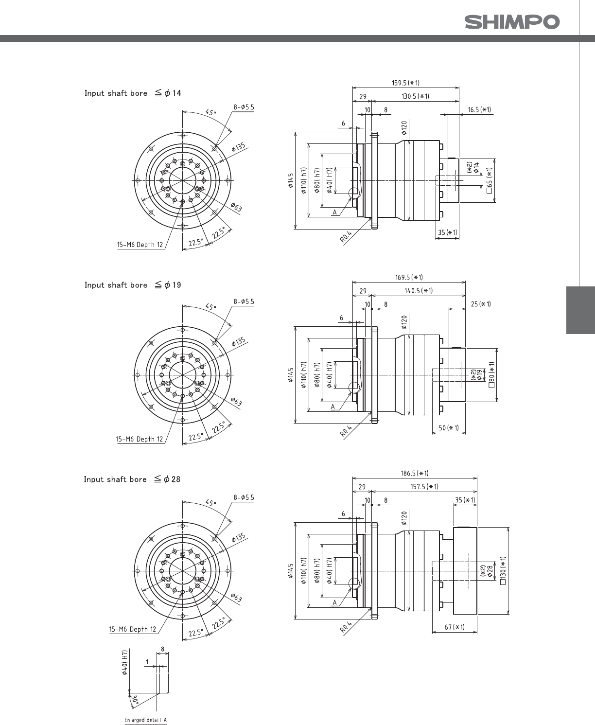
VRT
VRT- 2-Stage Dimensions
*1) Length will vary depending on motor
*2) Bushing will be inserted to adapt to motor shaft

VRT-SERIES Inline shaft
VRT- 1-Stage Adapter Dimensions
*1) Single reduction : /~ /
Model Number **: Adapter Code 1-Stage
L1 L* L2 L3 L4 L5
VRT-110-□-□-14**
(Input shaft bore ≦ φ14)
BA•BB•BD•BE•BF•BG•BH•BJ•BK•BP -- -- -- -- -- --
BC•BH•BM•BN -- -- -- -- -- --
CA•CC ------------
DA•DB•DC•DD•DF•DH•DJ -- -- -- -- -- --
EA•EB•EC•EF•EG•EK•EL -- -- -- -- -- --
FA -- -- -- -- -- --
FB -- -- -- -- -- --
JA -- -- -- -- -- --
VRT-110-□-□-19**
(Input shaft bore ≦ φ19)
DA • DB • DC 124.5 99.5 95.5 □80 25 50
EB 124.5 99.5 95.5 □90 25 50
FA 124.5 99.5 95.5 □100 25 50
FB 134.5 99.5 105.5 □100 35 60
GB • GD 124.5 99.5 95.5 □115 25 50
HA 134.5 99.5 105.5 □115 35 60
-- 124.5 99.5 95.5 □130 25 50
-- 139.5 99.5 110.5 □130 40 65
-- 129.5 99.5 100.5 □130 30 55
HB 134.5 99.5 105.5 □150 35 60
VRT-110-□-□-28**
(Input shaft bore ≦ φ28)
FA•FB•FC 141.5 106.5 112.5 □100 35 67
GA•GB•GC•GD•GE•GF•GG•GH 141.5 106.5 112.5 □115 35 67
HA•HC•HD 141.5 106.5 112.5 □130 35 67
HB 151.5 106.5 122.5 □130 45 77
HF 136.5 106.5 107.5 □130 30 62
JA•JB•JC•JF 141.5 106.5 112.5 □150 35 67
JD 161.5 106.5 132.5 □150 55 87
JE 151.5 106.5 122.5 □150 45 77
KA•KB•KE 141.5 106.5 112.5 □180 35 67
KD 151.5 106.5 122.5 □180 45 77
VRT-110-□-□-38**
(Input shaft bore ≦ φ38)
HA 162.5 117.5 133.5 □130 45 82
HB•HE 157.5 117.5 128.5 □130 40 77
JA 162.5 117.5 133.5 □150 45 82
KA•KB•KC 162.5 117.5 133.5 □180 45 82
KD 197.5 117.5 168.5 □180 80 117
KE 177.5 117.5 148.5 □180 60 97
A more comprehensive adapter ange o ering can be found using the NIDECSHIMPO Online Selector Tool. The variety is constantly
expanding and being updated on the Selector Tool. If you have any questions or need any support, contact NIDECSHIMPO.
For an explanation on the Adapter Flange Code, please turn to page .
*) Bushing will be inserted to adapt to motor shaft
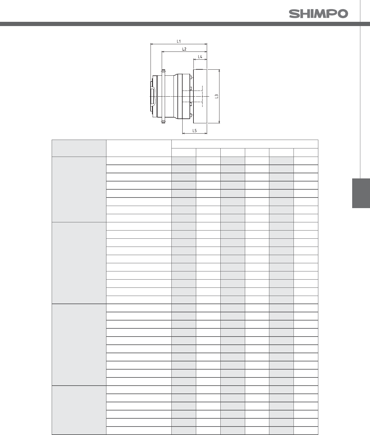
VRT
VRT- 2-Stage Adapter Dimensions
*1) Double reduction : /~ /
Model Number **: Adapter Code 2-Stage
L1 L* L2 L3 L4 L5
VRT-110-□-□-14**
(Input shaft bore ≦ φ14)
BA•BB•BD•BE•BF•BG•BH•BJ•BK•BP 142 125.5 113 □65 16.5 35
BC•BH•BM•BN 147 125.5 118 □65 21.5 40
CA•CC 142 125.5 113 □70 16.5 35
DA•DB•DC•DD•DF•DH•DJ 142 125.5 113 □80 16.5 35
EA•EB•EC•EF•EG•EK•EL 142 125.5 113 □90 16.5 35
FA 142 125.5 113 □100 16.5 35
FB 152 125.5 123 □100 26.5 45
JA 157 125.5 128 □150 31.5 50
VRT-110-□-□-19**
(Input shaft bore ≦ φ19)
DA • DB • DC 152 127 123 □80 25 50
EB 152 127 123 □90 25 50
FA 152 127 123 □100 25 50
FB 162 127 133 □100 35 60
GB • GD 152 127 123 □115 25 50
HA 162 127 133 □115 35 60
-- 152 127 123 □130 25 50
-- 167 127 138 □130 40 65
-- 157 127 128 □130 30 55
HB 162 127 133 □150 35 60
VRT-110-□-□-28**
(Input shaft bore ≦ φ28)
FA•FB•FC 169 134 140 □100 35 67
GA•GB•GC•GD•GE•GF•GG•GH 169 134 140 □115 35 67
HA•HC•HD 169 134 140 □130 35 67
HB 179 134 150 □130 45 77
HF 164 134 135 □130 30 62
JA•JB•JC•JF 169 134 140 □150 35 67
JD 189 134 160 □150 55 87
JE 179 134 150 □150 45 77
KA•KB•KE 169 134 140 □180 35 67
KD 179 134 150 □180 45 77
VRT-110-□-□-38**
(Input shaft bore ≦ φ38)
HA 186.5 141.5 157.5 □130 45 82
HB•HE 181.5 141.5 152.5 □130 40 77
JA 186.5 141.5 157.5 □150 45 82
KA•KB•KC 186.5 141.5 157.5 □180 45 82
KD 221.5 141.5 192.5 □180 80 117
KE 201.5 141.5 172.5 □180 60 97
A more comprehensive adapter ange o ering can be found using the NIDECSHIMPO Online Selector Tool. The variety is constantly
expanding and being updated on the Selector Tool. If you have any questions or need any support, contact NIDECSHIMPO.
For an explanation on the Adapter Flange Code, please turn to page .
*) Bushing will be inserted to adapt to motor shaft

VRT-SERIES Inline shaft
VRT- 1-Stage Specifications
VRT- 2-Stage Specifications
Frame Size 140
Stage 1-Stage
Ratio Unit Note 4 5 7 10
Nominal Output Torque [Nm] *1 240 360 360 240
Maximum Output Torque [Nm] *2 700 700 700 470
Emergency Stop Torque [Nm] *3 1250 1250 1250 1000
Nominal Input Speed [rpm] *4 2000
Maximum Input Speed [rpm] *5 4000
No Load Running Torque [Nm] *13 1.00
Permitted Radial Load [N] *6 8000 8500 9400 10000
Permitted Axial Load [N] *7 5600 6000 6700 7400
Maximum Radial Load [N] *8 19000
Maximum Axial Load [N] *9 14000
Moment of Inertia (≤ Ø 19) [kgcm2] *10 -- -- -- --
Moment of Inertia (≤ Ø 28) [kgcm2] -- 11.000 8.400 5.400 4.100
Moment of Inertia (≤ Ø 38) [kgcm2] -- 19.000 16.000 13.000 12.000
Moment of Inertia (≤ Ø 48) [kgcm2] -- 41.000 38.000 35.000 34.000
E ciency [%] -- 95
Torsional Rigidity [Nm/arcmin] *11 60
Maximum Torsional Backlash [Arc-min] *12 ≤ 3
Noise Level [dB] -- ≤ 67
Protection Class -- *14 IP54 (IP65)
Ambient Temperature [°C] -- 0 - 40
Permitted Housing Temperature [°C] -- 90
Weight [kg] *15 15
Frame Size 140
Stage 2-Stage
Ratio Unit Note 16 20 25 28
Nominal Output Torque [Nm] *1 360 360 360 360
Maximum Output Torque [Nm] *2 700 700 700 700
Emergency Stop Torque [Nm] *3 1250 1250 1250 1250
Nominal Input Speed [rpm] *4 2000
Maximum Input Speed [rpm] *5 4000
No Load Running Torque [Nm] *13 0.54
Permitted Radial Load [N] *6 12000 13000 14000 14000
Permitted Axial Load [N] *7 8500 9100 9800 10000
Maximum Radial Load [N] *8 19000
Maximum Axial Load [N] *9 14000
Moment of Inertia (≤ Ø 19) [kgcm2] *10 3.800 2.600 2.500 3.400
Moment of Inertia (≤ Ø 28) [kgcm2] -- 5.800 4.600 4.500 5.400
Moment of Inertia (≤ Ø 38) [kgcm2] -- 13.000 12.000 12.000 13.000
Moment of Inertia (≤ Ø 48) [kgcm2] -- 35.000 34.000 34.000 35.000
E ciency [%] -- 90
Torsional Rigidity [Nm/arcmin] *11 60
Maximum Torsional Backlash [Arc-min] *12 ≤ 3
Noise Level [dB] -- ≤ 67
Protection Class -- *14 IP54 (IP65)
Ambient Temperature [°C] -- 0 - 40
Permitted Housing Temperature [°C] -- 90
Weight [kg] *15 17

VRT
VRT- 2-Stage Specifications
*1) At nominal input speed, service life is , hours
*2) The maximum torque when starting or stopping operation
*3) The maximum torque allowed under a stress situation (Permitted , times during service life)
*4) The average input speed
*5) The maximum intermittent input speed
*6) This is the torque at no load applied on the input shaft. The input speed is , rpm for VRT
*7) At this load and nominal input speed, service life will be , hours. (The radial load applied to the output side bearing)
*8) At this load and nominal input speed, service life will be , hours. (The axial load applied to the output ange center)
*9) The maximum radial load that the reducer can accept
*10) The maximum axial load that the reducer can accept
*11) The e ciency at the nominal torque rating
*12) This does not include the lost motion
*13) Contact NIDEC-SHIMPO for the testing conditions and environment
*14) IP (wash-down) is available as an option. Contact NIDECSHIMPO for more details and our food grade options
*15) The weight may vary slightly between models
Frame Size 140
Stage 2-Stage
Ratio Unit Note 35 40 50 70 100
Nominal Output Torque [Nm] *1 360 360 360 360 240
Maximum Output Torque [Nm] *2 700 700 700 700 470
Emergency Stop Torque [Nm] *3 1250 1250 1250 1250 1000
Nominal Input Speed [rpm] *4 2000
Maximum Input Speed [rpm] *5 4000
No Load Running Torque [Nm] *13 0.54
Permitted Radial Load [N] *6 15000 16000 17000 19000 19000
Permitted Axial Load [N] *7 11000 11000 12000 13000 14000
Maximum Radial Load [N] *8 19000
Maximum Axial Load [N] *9 14000
Moment of Inertia (≤ Ø 19) [kgcm2] *10 2.400 1.200 1.100 1.100 1.100
Moment of Inertia (≤ Ø 28) [kgcm2] -- 4.400 3.100 3.100 3.100 3.100
Moment of Inertia (≤ Ø 38) [kgcm2] -- 12.000 11.000 11.000 11.000 11.000
Moment of Inertia (≤ Ø 48) [kgcm2] -- 34.000 33.000 33.000 33.000 33.000
E ciency [%] -- 90
Torsional Rigidity [Nm/arcmin] *11 60
Maximum Torsional Backlash [Arc-min] *12 ≤ 3
Noise Level [dB] -- ≤ 67
Protection Class -- *14 IP54 (IP65)
Ambient Temperature [°C] -- 0 - 40
Permitted Housing Temperature [°C] -- 90
Weight [kg] *15 17

VRT-SERIES Inline shaft
VRT- 1-Stage Dimensions
*1) Length will vary depending on motor.
*2) Bushing will be inserted to adapt to motor shaft

VRT
VRT- 2-Stage Dimensions
*1) Length will vary depending on motor.
*2) Bushing will be inserted to adapt to motor shaft

VRT-SERIES Inline shaft
VRT- 1-Stage Adapter Dimensions
*1) Single reduction : /~ /
Model Number **: Adapter Code 1-Stage
L1 L* L2 L3 L4 L5
VRT-140-□-□-19**
(Input shaft bore ≦ φ19)
DA•DB•DC -- -- -- -- -- --
EB•ED -- -- -- -- -- --
FA -- -- -- -- -- --
FB -- -- -- -- -- --
GB•GD•GJ -- -- -- -- -- --
HA -- -- -- -- -- --
HB -- -- -- -- -- --
JA -- -- -- -- -- --
VRT-140-□-□-28**
(Input shaft bore ≦ φ28)
FA•FB•FC 154 119 116 □100 35 67
GA•GB•GC•GD•GE•GF•GG•GH 154 119 116 □115 35 67
HA•HC•HD 154 119 116 □130 35 67
HB 164 119 126 □130 45 77
HF 149 119 111 □130 30 62
JA•JB•JC•JF 154 119 116 □150 35 67
KA•KB•KE 154 119 116 □180 35 67
LA 154 119 116 □200 35 67
LB 164 119 126 □200 45 77
MA 154 119 116 □220 35 67
MB 164 119 126 □220 45 77
VRT-140-□-□-38**
(Input shaft bore ≦ φ38)
HA 169 124 131 □130 45 82
HB•HE 164 124 126 □130 40 77
JA 169 124 131 □150 45 82
KA•KB•KC 169 124 131 □180 45 82
KD 204 124 166 □180 80 117
KE 184 124 146 □180 60 97
LB 179 124 141 □200 55 92
MA•MB 169 124 131 □220 45 82
MC 184 124 146 □220 60 97
MD 179 124 141 □220 55 92
VRT-140-□-□-48**
(Input shaft bore ≦ φ48)
KA 210 135 172 □180 75 118
KB•KC 190 135 152 □180 55 98
LA 190 135 152 □200 55 98
MA 190 135 152 □220 55 98
MB 210 135 172 □220 75 118
A more comprehensive adapter ange o ering can be found using the NIDECSHIMPO Online Selector Tool. The variety is constantly
expanding and being updated on the Selector Tool. If you have any questions or need any support, contact NIDECSHIMPO.
For an explanation on the Adapter Flange Code, please turn to page .
*) Bushing will be inserted to adapt to motor shaft

VRT
VRT- 2-Stage Adapter Dimensions
*1) Double reduction : /~ /
Model Number **: Adapter Code 2-Stage
L1 L* L2 L3 L4 L5
VRT-140-□-□-19**
(Input shaft bore ≦ φ19)
DA•DB•DC 171.5 146.5 133.5 □80 25 50
EB•ED 171.5 146.5 133.5 □90 25 50
FA 171.5 146.5 133.5 □100 25 50
FB 181.5 146.5 143.5 □100 35 60
GB•GD•GJ 171.5 146.5 133.5 □115 25 50
HA 171.5 146.5 133.5 □130 25 50
HB 186.5 146.5 148.5 □130 40 65
JA 181.5 146.5 143.5 □150 35 60
VRT-140-□-□-28**
(Input shaft bore ≦ φ28)
FA•FB•FC 188.5 153.5 150.5 □100 35 67
GA•GB•GC•GD•GE•GF•GG•GH 188.5 153.5 150.5 □115 35 67
HA•HC•HD 188.5 153.5 150.5 □130 35 67
HB 198.5 153.5 160.5 □130 45 77
HF 183.5 153.5 145.5 □130 30 62
JA•JB•JC•JF 188.5 153.5 150.5 □150 35 67
KA•KB•KE 188.5 153.5 150.5 □180 35 67
LA 188.5 153.5 150.5 □200 35 67
LB 198.5 153.5 160.5 □200 45 77
MA 188.5 153.5 150.5 □220 35 67
MB 198.5 153.5 160.5 □220 45 77
VRT-140-□-□-38**
(Input shaft bore ≦ φ38)
HA 203.5 158.5 165.5 □130 45 82
HB•HE 198.5 158.5 160.5 □130 40 77
JA 203.5 158.5 165.5 □150 45 82
KA•KB•KC 203.5 158.5 165.5 □180 45 82
KD 238.5 158.5 200.5 □180 80 117
KE 218.5 158.5 180.5 □180 60 97
LB 213.5 158.5 175.5 □200 55 92
MA•MB 203.5 158.5 165.5 □220 45 82
MC 218.5 158.5 180.5 □220 60 97
MD 213.5 158.5 175.5 □220 55 92
VRT-140-□-□-48**
(Input shaft bore ≦ φ48)
KA 244.5 169.5 206.5 □180 75 118
KB•KC 224.5 169.5 186.5 □180 55 98
LA 224.5 169.5 186.5 □200 55 98
MA 224.5 169.5 186.5 □220 55 98
MB 244.5 169.5 206.5 □220 75 118
A more comprehensive adapter ange o ering can be found using the NIDECSHIMPO Online Selector Tool. The variety is constantly
expanding and being updated on the Selector Tool. If you have any questions or need any support, contact NIDECSHIMPO.
For an explanation on the Adapter Flange Code, please turn to page .
*) Bushing will be inserted to adapt to motor shaft

VRT-SERIES Inline shaft
VRT- 1-Stage Specifications
VRT- 2-Stage Specifications
Frame Size 200
Stage 1-Stage
Ratio Unit Note 4 5 7 10
Nominal Output Torque [Nm] *1 750 750 750 500
Maximum Output Torque [Nm] *2 1400 1400 1400 970
Emergency Stop Torque [Nm] *3 2750 2750 2750 2200
Nominal Input Speed [rpm] *4 1500
Maximum Input Speed [rpm] *5 3000
No Load Running Torque [Nm] *13 1.9
Permitted Radial Load [N] *6 18000 19000 21000 23000
Permitted Axial Load [N] *7 12000 13000 14000 16000
Maximum Radial Load [N] *8 40000
Maximum Axial Load [N] *9 30000
Moment of Inertia (≤ Ø 28) [kgcm2] *10 -- -- -- --
Moment of Inertia (≤ Ø 38) [kgcm2] -- 54.000 39.000 25.000 18.000
Moment of Inertia (≤ Ø 48) [kgcm2] -- 76.000 61.000 47.000 40.000
Moment of Inertia (≤ Ø 65) [kgcm2] -- 140.000 120.000 110.000 100.000
E ciency [%] -- 95
Torsional Rigidity [Nm/arcmin] *11 175
Maximum Torsional Backlash [Arc-min] *12 ≤ 3
Noise Level [dB] -- ≤ 67
Protection Class -- *14 IP54 (IP65)
Ambient Temperature [°C] -- 0 - 40
Permitted Housing Temperature [°C] -- 90
Weight [kg] *15 42
Frame Size 200
Stage 2-Stage
Ratio Unit Note 16 20 25 28
Nominal Output Torque [Nm] *1 750 750 750 750
Maximum Output Torque [Nm] *2 1400 1400 1400 1400
Emergency Stop Torque [Nm] *3 2750 2750 2750 2750
Nominal Input Speed [rpm] *4 1500
Maximum Input Speed [rpm] *5 3000
No Load Running Torque [Nm] *13 1.3
Permitted Radial Load [N] *6 27000 28000 30000 31000
Permitted Axial Load [N] *7 18000 19000 21000 21000
Maximum Radial Load [N] *8 40000
Maximum Axial Load [N] *9 30000
Moment of Inertia (≤ Ø 28) [kgcm2] *10 13.000 9.400 8.800 11.000
Moment of Inertia (≤ Ø 38) [kgcm2] -- 21.000 17.000 16.000 19.000
Moment of Inertia (≤ Ø 48) [kgcm2] -- 43.000 39.000 38.000 41.000
Moment of Inertia (≤ Ø 65) [kgcm2] -- -- -- -- --
E ciency [%] -- 90
Torsional Rigidity [Nm/arcmin] *11 175
Maximum Torsional Backlash [Arc-min] *12 ≤ 3
Noise Level [dB] -- ≤ 67
Protection Class -- *14 IP54 (IP65)
Ambient Temperature [°C] -- 0 - 40
Permitted Housing Temperature [°C] -- 90
Weight [kg] *15 43

VRT
VRT- 2-Stage Specifications
*1) At nominal input speed, service life is , hours
*2) The maximum torque when starting or stopping operation
*3) The maximum torque allowed under a stress situation (Permitted , times during service life)
*4) The average input speed
*5) The maximum intermittent input speed
*6) This is the torque at no load applied on the input shaft. The input speed is , rpm for VRT
*7) At this load and nominal input speed, service life will be , hours. (The radial load applied to the output side bearing)
*8) At this load and nominal input speed, service life will be , hours. (The axial load applied to the output ange center)
*9) The maximum radial load that the reducer can accept
*10) The maximum axial load that the reducer can accept
*11) The e ciency at the nominal torque rating
*12) This does not include the lost motion
*13) Contact NIDEC-SHIMPO for the testing conditions and environment
*14) IP (wash-down) is available as an option. Contact NIDECSHIMPO for more details and our food grade options
*15) The weight may vary slightly between models
Frame Size 200
Stage 2-Stage
Ratio Unit Note 35 40 50 70 100
Nominal Output Torque [Nm] *1 750 750 750 750 500
Maximum Output Torque [Nm] *2 1400 1400 1400 1400 970
Emergency Stop Torque [Nm] *3 2750 2750 2750 2750 2200
Nominal Input Speed [rpm] *4 1500
Maximum Input Speed [rpm] *5 3000
No Load Running Torque [Nm] *13 1.3
Permitted Radial Load [N] *6 34000 35000 37000 40000 40000
Permitted Axial Load [N] *7 23000 24000 25000 28000 30000
Maximum Radial Load [N] *8 40000
Maximum Axial Load [N] *9 30000
Moment of Inertia (≤ Ø 28) [kgcm2] *10 8.200 4.400 4.200 4.100 4.000
Moment of Inertia (≤ Ø 38) [kgcm2] -- 16.000 12.000 12.000 12.000 12.000
Moment of Inertia (≤ Ø 48) [kgcm2] -- 38.000 34.000 34.000 34.000 34.000
Moment of Inertia (≤ Ø 65) [kgcm2] -- -- -- -- -- --
E ciency [%] -- 90
Torsional Rigidity [Nm/arcmin] *11 175
Maximum Torsional Backlash [Arc-min] *12 ≤ 3
Noise Level [dB] -- ≤ 67
Protection Class -- *14 IP54 (IP65)
Ambient Temperature [°C] -- 0 - 40
Permitted Housing Temperature [°C] -- 90
Weight [kg] *15 43
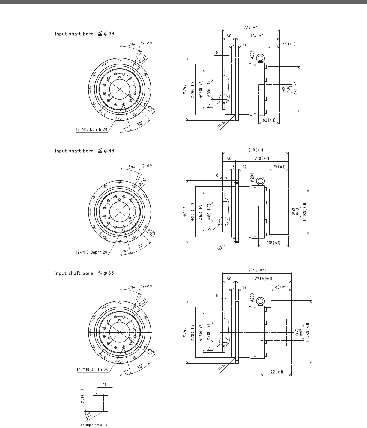
VRT-SERIES Inline shaft
VRT- 1-Stage Dimensions
*1) Length will vary depending on motor
*2) Bushing will be inserted to adapt to motor shaft

VRT
VRT- 2-Stage Dimensions
*1) Length will vary depending on motor
*2) Bushing will be inserted to adapt to motor shaft

VRT-SERIES Inline shaft
VRT- 1-Stage Adapter Dimensions
*1) Single reduction : /~ /
Model Number **: Adapter Code 1-Stage
L1 L* L2 L3 L4 L5
VRT-200-□-□-28**
(Input shaft bore ≦ φ28)
FA•FB•FC -- -- -- -- -- --
GA•GB•GC•GD•GE•GF•GG•GH -- -- -- -- -- --
HA•HC•HD -- -- -- -- -- --
HB -- -- -- -- -- --
HF -- -- -- -- -- --
JA•JB•JC•JF -- -- -- -- -- --
KA•KB•KE -- -- -- -- -- --
LA -- -- -- -- -- --
LB -- -- -- -- -- --
MA -- -- -- -- -- --
MB -- -- -- -- -- --
VRT-200-□-□-38**
(Input shaft bore ≦ φ38)
HA 192 147 142 □130 45 82
HB•HE 187 147 137 □130 40 77
JA 192 147 142 □150 45 82
KA•KB•KC 192 147 142 □180 45 82
KD 227 147 177 □180 80 117
KE 207 147 157 □180 60 97
LB 202 147 152 □200 55 92
MA•MB 192 147 142 □220 45 82
MC 207 147 157 □220 60 97
MD 202 147 152 □220 55 92
NA 192 147 142 □250 45 82
VRT-200-□-□-48**
(Input shaft bore ≦ φ48)
KA 228 153 178 □180 75 118
KB•KC 208 153 158 □180 55 98
LA 208 153 158 □200 55 98
MA 208 153 158 □220 55 98
MB 228 153 178 □220 75 118
NA 228 153 178 □250 75 118
PA 228 153 178 □280 75 118
VRT-200-□-□-65**
(Input shaft bore ≦ φ65)
MA•MB•MC•MD 239.5 159.5 189.5 □220 80 122
NA•NC 239.5 159.5 189.5 □250 80 122
NB•ND 269.5 159.5 219.5 □250 110 152
PA 259.5 159.5 209.5 □280 100 142
PB 269.5 159.5 219.5 □280 110 152
A more comprehensive adapter ange o ering can be found using the NIDECSHIMPO Online Selector Tool. The variety is constantly
expanding and being updated on the Selector Tool. If you have any questions or need any support, contact NIDECSHIMPO.
For an explanation on the Adapter Flange Code, please turn to page .
*) Bushing will be inserted to adapt to motor shaft

VRT
VRT- 2-Stage Adapter Dimensions
Model Number **: Adapter Code 2-Stage
L1 L* L2 L3 L4 L5
VRT-200-□-□-28**
(Input shaft bore ≦ φ28)
FA•FB•FC 221.5 186.5 171.5 □100 35 67
GA•GB•GC•GD•GE•GF•GG•GH 221.5 186.5 171.5 □115 35 67
HA•HC•HD 221.5 186.5 171.5 □130 35 67
HB 231.5 186.5 181.5 □130 45 77
HF 216.5 186.5 166.5 □130 30 62
JA•JB•JC•JF 221.5 186.5 171.5 □150 35 67
KA•KB•KE 221.5 186.5 171.5 □180 35 67
LA 221.5 186.5 171.5 □200 35 67
LB 231.5 186.5 181.5 □200 45 77
MA 221.5 186.5 171.5 □220 35 67
MB 231.5 186.5 181.5 □220 45 77
VRT-200-□-□-38**
(Input shaft bore ≦ φ38)
HA 236.5 191.5 186.5 □130 45 82
HB•HE 231.5 191.5 181.5 □130 40 77
JA 236.5 191.5 186.5 □150 45 82
KA•KB•KC 236.5 191.5 186.5 □180 45 82
KD 271.5 191.5 221.5 □180 80 117
KE 251.5 191.5 201.5 □180 60 97
LB 246.5 191.5 196.5 □200 55 92
MA•MB 236.5 191.5 186.5 □220 45 82
MC 251.5 191.5 201.5 □220 60 97
MD 246.5 191.5 196.5 □220 55 92
NA 236.5 191.5 186.5 □250 45 82
VRT-200-□-□-48**
(Input shaft bore ≦ φ48)
KA 272.5 197.5 222.5 □180 75 118
KB•KC 252.5 197.5 202.5 □180 55 98
LA 252.5 197.5 202.5 □200 55 98
MA 252.5 197.5 202.5 □220 55 98
MB 272.5 197.5 222.5 □220 75 118
NA 272.5 197.5 222.5 □250 75 118
PA 272.5 197.5 222.5 □280 75 118
VRT-200-□-□-65**
(Input shaft bore ≦ φ65)
MA•MB•MC•MD -- -- -- -- -- --
NA•NC -- -- -- -- -- --
NB•ND -- -- -- -- -- --
PA -- -- -- -- -- --
PB -- -- -- -- -- --
*1) Double reduction : /~ /
A more comprehensive adapter ange o ering can be found using the NIDECSHIMPO Online Selector Tool. The variety is constantly
expanding and being updated on the Selector Tool. If you have any questions or need any support, contact NIDECSHIMPO.
For an explanation on the Adapter Flange Code, please turn to page .
*) Bushing will be inserted to adapt to motor shaft

VRT-SERIES Inline shaft
VRT- 1-Stage Specifications
VRT- 2-Stage Specifications
Frame Size 255
Stage 1-Stage
Ratio Unit Note 4 5 7 10
Nominal Output Torque [Nm] *1 2400 2400 2400 1600
Maximum Output Torque [Nm] *2 3700 3700 3700 2600
Emergency Stop Torque [Nm] *3 8000 8000 8000 6000
Nominal Input Speed [rpm] *4 1000
Maximum Input Speed [rpm] *5 2000
No Load Running Torque [Nm] *13 2.5
Permitted Radial Load [N] *6 31000 33000 36000 40000
Permitted Axial Load [N] *7 22000 24000 26000 29000
Maximum Radial Load [N] *8 64000
Maximum Axial Load [N] *9 48000
Moment of Inertia (≤ Ø 48) [kgcm2] *10 -- -- -- --
Moment of Inertia (≤ Ø 65) [kgcm2] -- 200 170 130 110
E ciency [%] -- 95
Torsional Rigidity [Nm/arcmin] *11 550
Maximum Torsional Backlash [Arc-min] *12 ≤ 3
Noise Level [dB] -- ≤ 62
Protection Class -- *14 IP54 (IP65)
Ambient Temperature [°C] -- 0 - 40
Permitted Housing Temperature [°C] -- 90
Weight [kg] *15 84
Frame Size 255
Stage 2-Stage
Ratio Unit Note 16 20 25 28
Nominal Output Torque [Nm] *1 2400 2400 2400 2400
Maximum Output Torque [Nm] *2 3700 3700 3700 3700
Emergency Stop Torque [Nm] *3 8000 8000 8000 8000
Nominal Input Speed [rpm] *4 1000
Maximum Input Speed [rpm] *5 2000
No Load Running Torque [Nm] *13 1.0
Permitted Radial Load [N] *6 46000 49000 53000 55000
Permitted Axial Load [N] *7 34000 36000 38000 40000
Maximum Radial Load [N] *8 64000
Maximum Axial Load [N] *9 48000
Moment of Inertia (≤ Ø 48) [kgcm2] *10 64.0 53.0 51.0 59.0
Moment of Inertia (≤ Ø 65) [kgcm2] -- -- -- -- --
E ciency [%] -- 90
Torsional Rigidity [Nm/arcmin] *11 550
Maximum Torsional Backlash [Arc-min] *12 ≤ 3
Noise Level [dB] -- ≤ 62
Protection Class -- *14 IP54 (IP65)
Ambient Temperature [°C] -- 0 - 40
Permitted Housing Temperature [°C] -- 90
Weight [kg] *15 89

VRT
VRT- 2-Stage Specifications
*1) At nominal input speed, service life is , hours
*2) The maximum torque when starting or stopping operation
*3) The maximum torque allowed under a stress situation (Permitted , times during service life)
*4) The average input speed
*5) The maximum intermittent input speed
*6) This is the torque at no load applied on the input shaft. The input speed is , rpm for
*7) At this load and nominal input speed, service life will be , hours. (The radial load applied to the output side bearing)
*8) At this load and nominal input speed, service life will be , hours. (The axial load applied to the output ange center)
*9) The maximum radial load that the reducer can accept
*10) The maximum axial load that the reducer can accept
*11) The e ciency at the nominal torque rating
*12) This does not include the lost motion
*13) Contact NIDEC-SHIMPO for the testing conditions and environment
*14) IP (wash-down) is available as an option. Contact NIDECSHIMPO for more details and our food grade options
*15) The weight may vary slightly between models
Frame Size 255
Stage 2-Stage
Ratio Unit Note 35 40 50 70 100
Nominal Output Torque [Nm] *1 2400 2400 2400 2400 1600
Maximum Output Torque [Nm] *2 3700 3700 3700 3700 1800
Emergency Stop Torque [Nm] *3 8000 8000 8000 8000 6000
Nominal Input Speed [rpm] *4 1000
Maximum Input Speed [rpm] *5 2000
No Load Running Torque [Nm] *13 1.0
Permitted Radial Load [N] *6 59000 61000 64000 64000 64000
Permitted Axial Load [N] *7 42000 44000 47000 48000 48000
Maximum Radial Load [N] *8 64000
Maximum Axial Load [N] *9 48000
Moment of Inertia (≤ Ø 48) [kgcm2] *10 50.0 38.0 38.0 37.0 37.0
Moment of Inertia (≤ Ø 65) [kgcm2] -- -- -- -- -- --
E ciency [%] -- 90
Torsional Rigidity [Nm/arcmin] *11 550
Maximum Torsional Backlash [Arc-min] *12 ≤ 3
Noise Level [dB] -- ≤ 62
Protection Class -- *14 IP54 (IP65)
Ambient Temperature [°C] -- 0 - 40
Permitted Housing Temperature [°C] -- 90
Weight [kg] *15 89
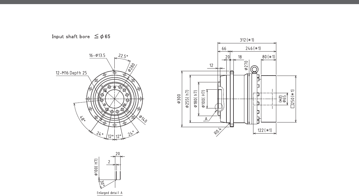
VRT-SERIES Inline shaft
VRT- 1-Stage Dimensions
*1) Length will vary depending on motor
*2) Bushing will be inserted to adapt to motor shaft

VRT
VRT- 2-Stage Dimensions
*1) Length will vary depending on motor
*2) Bushing will be inserted to adapt to motor shaft
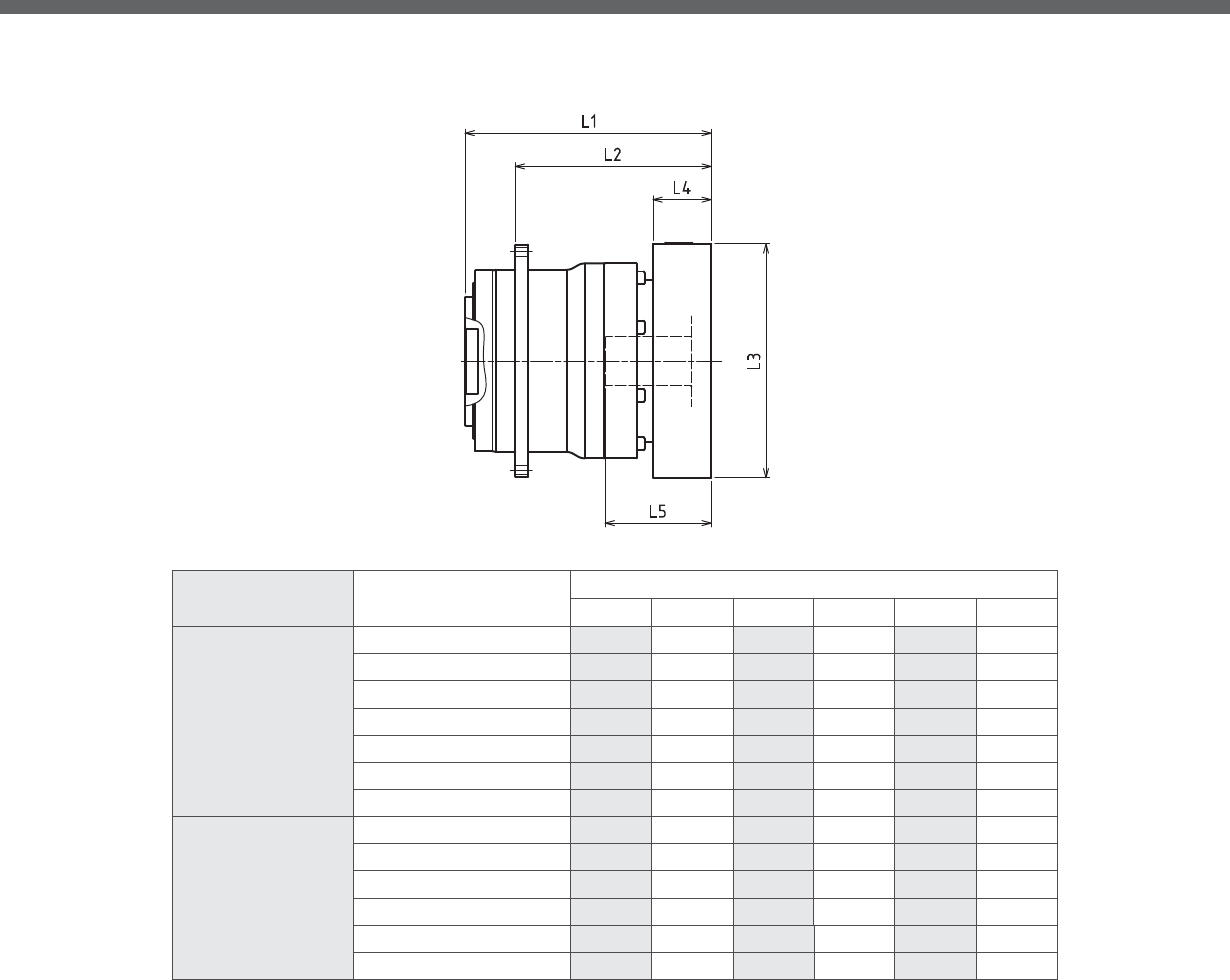
VRT-SERIES Inline shaft
VRT- 1-Stage Adapter Dimensions
*1) Single reduction : / - /
*2) Bushing will be inserted to adapt to motor shaft
Model Number **: Adapter Code 1-Stage
L1 L* L2 L3 L4 L5
VRT-255-□-□-48**
(Input shaft bore ≦ φ48)
KA -- -- -- -- -- --
KB•KC -- -- -- -- -- --
LA -- -- -- -- -- --
MA -- -- -- -- -- --
MB -- -- -- -- -- --
NA -- -- -- -- -- --
PA -- -- -- -- -- --
VRT-255-□-□-65**
(Input shaft bore ≦ φ65)
MA•MB•MC•MD 272 192 206 □220 80 122
NA•NC 272 192 206 □250 80 122
NB•ND 302 192 236 □250 110 152
PA 292 192 226 □280 100 142
PB 302 192 236 □280 110 152
QA•QB 292 192 226 □320 100 142
A more comprehensive adapter ange o ering can be found using the NIDECSHIMPO Online Selector Tool. The variety is constantly
expanding and being updated on the Selector Tool. If you have any questions or need any support, contact NIDECSHIMPO.
For an explanation on the Adapter Flange Code, please turn to page .

VRT
VRT- 2-Stage Adapter Dimensions
*1) Double reduction : / - /
*2) Bushing will be inserted to adapt to motor shaft
Model Number **: Adapter Code 2-Stage
L1 L* L2 L3 L4 L5
VRT-255-□-□-48**
(Input shaft bore ≦ φ48)
KA 322.5 247.5 256.5 □180 75 118
KB•KC 302.5 247.5 236.5 □180 55 98
LA 302.5 247.5 236.5 □200 55 98
MA 302.5 247.5 236.5 □220 55 98
MB 322.5 247.5 256.5 □220 75 118
NA 322.5 247.5 256.5 □250 75 118
PA 322.5 247.5 256.5 □280 75 118
VRT-255-□-□-65**
(Input shaft bore ≦ φ65)
MA•MB•MC•MD -- -- -- -- -- --
NA•NC -- -- -- -- -- --
NB•ND -- -- -- -- -- --
PA -- -- -- -- -- --
PB -- -- -- -- -- --
QA•QB -- -- -- -- -- --
A more comprehensive adapter ange o ering can be found using the NIDECSHIMPO Online Selector Tool. The variety is constantly
expanding and being updated on the Selector Tool. If you have any questions or need any support, contact NIDECSHIMPO.
For an explanation on the Adapter Flange Code, please turn to page .

VRT-SERIES Inline shaft
VRT- 1-Stage Specifications
VRT- 2-Stage Specifications
Frame Size 285
Stage 1-Stage
Ratio Unit Note 4 5 7 10
Nominal Output Torque [Nm] *1 3300 3300 3300 2200
Maximum Output Torque [Nm] *2 5300 5300 5300 3700
Emergency Stop Torque [Nm] *3 12000 12000 12000 10000
Nominal Input Speed [rpm] *4 1000
Maximum Input Speed [rpm] *5 2000
No Load Running Torque [Nm] *13 2.7
Permitted Radial Load [N] *6 40000 42000 47000 52000
Permitted Axial Load [N] *7 34000 36000 40000 45000
Maximum Radial Load [N] *8 86000
Maximum Axial Load [N] *9 64000
Moment of Inertia (≤ Ø 48) [kgcm2] *10 -- -- -- --
Moment of Inertia (≤ Ø 65) [kgcm2] -- 250 200 140 120
E ciency [%] -- 95
Torsional Rigidity [Nm/arcmin] *11 850
Maximum Torsional Backlash [Arc-min] *12 ≤ 3
Noise Level [dB] -- ≤ 63
Protection Class -- *14 IP54 (IP65)
Ambient Temperature [°C] -- 0 - 40
Permitted Housing Temperature [°C] -- 90
Weight [kg] *15 110
Frame Size 285
Stage 2-Stage
Ratio Unit Note 16 20 25 28
Nominal Output Torque [Nm] *1 2750 3300 3300 3300
Maximum Output Torque [Nm] *2 5300 5300 5300 5300
Emergency Stop Torque [Nm] *3 12000 12000 12000 12000
Nominal Input Speed [rpm] *4 1000
Maximum Input Speed [rpm] *5 2000
No Load Running Torque [Nm] *13 0.6
Permitted Radial Load [N] *6 60000 64000 69000 71000
Permitted Axial Load [N] *7 51000 55000 59000 61000
Maximum Radial Load [N] *8 86000
Maximum Axial Load [N] *9 64000
Moment of Inertia (≤ Ø 48) [kgcm2] *10 48.0 42.0 41.0 42.0
Moment of Inertia (≤ Ø 65) [kgcm2] -- -- -- -- --
E ciency [%] -- 90
Torsional Rigidity [Nm/arcmin] *11 850
Maximum Torsional Backlash [Arc-min] *12 ≤ 3
Noise Level [dB] -- ≤ 63
Protection Class -- *14 IP54 (IP65)
Ambient Temperature [°C] -- 0 - 40
Permitted Housing Temperature [°C] -- 90
Weight [kg] *15 120

VRT
VRT- 2-Stage Specifications
*1) At nominal input speed, service life is , hours
*2) The maximum torque when starting or stopping operation
*3) The maximum torque allowed under a stress situation (Permitted , times during service life)
*4) The average input speed
*5) The maximum intermittent input speed
*6) This is the torque at no load applied on the input shaft. The input speed is , rpm for VRT
*7) At this load and nominal input speed, service life will be , hours. (The radial load applied to the output side bearing)
*8) At this load and nominal input speed, service life will be , hours. (The axial load applied to the output ange center)
*9) The maximum radial load that the reducer can accept
*10) The maximum axial load that the reducer can accept
*11) The e ciency at the nominal torque rating
*12) This does not include the lost motion
*13) Contact NIDEC-SHIMPO for the testing conditions and environment
*14) IP (wash-down) is available as an option. Contact NIDECSHIMPO for more details and our food grade options
*15) The weight may vary slightly between models
Frame Size 285
Stage 2-Stage
Ratio Unit Note 35 40 50 70 100
Nominal Output Torque [Nm] *1 3300 3300 3300 3300 2200
Maximum Output Torque [Nm] *2 5300 5300 5300 5300 2500
Emergency Stop Torque [Nm] *3 12000 12000 12000 12000 10000
Nominal Input Speed [rpm] *4 1000
Maximum Input Speed [rpm] *5 2000
No Load Running Torque [Nm] *13 0.6
Permitted Radial Load [N] *6 76000 79000 85000 86000 86000
Permitted Axial Load [N] *7 64000 64000 64000 64000 64000
Maximum Radial Load [N] *8 86000
Maximum Axial Load [N] *9 64000
Moment of Inertia (≤ Ø 48) [kgcm2] *10 39.0 36.0 35.0 35.0 35.0
Moment of Inertia (≤ Ø 65) [kgcm2] -- -- -- -- -- --
E ciency [%] -- 90
Torsional Rigidity [Nm/arcmin] *11 850
Maximum Torsional Backlash [Arc-min] *12 ≤ 3
Noise Level [dB] -- ≤ 63
Protection Class -- *14 IP54 (IP65)
Ambient Temperature [°C] -- 0 - 40
Permitted Housing Temperature [°C] -- 90
Weight [kg] *15 120
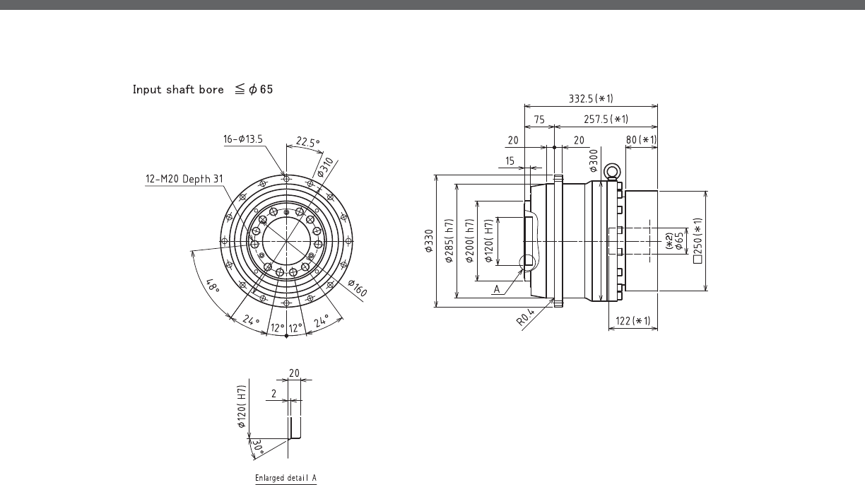
VRT-SERIES Inline shaft
VRT- 1-Stage Dimensions
*1) Length will vary depending on motor
*2) Bushing will be inserted to adapt to motor shaft

VRT
VRT- 2-Stage Dimensions
*1) Length will vary depending on motor
*2) Bushing will be inserted to adapt to motor shaft

VRT-SERIES Inline shaft
VRT- 1-Stage Adapter Dimensions
*1) Single reduction : /~ /
*2) Bushing will be inserted to adapt to motor shaft
Model Number **: Adapter Code 1-Stage
L1 L* L2 L3 L4 L5
VRT-285-□-□-48**
(Input shaft bore ≦ φ48)
KA -- -- -- -- -- --
KB•KC -- -- -- -- -- --
LA -- -- -- -- -- --
MA -- -- -- -- -- --
MB -- -- -- -- -- --
NA -- -- -- -- -- --
PA -- -- -- -- -- --
VRT-285-□-□-65**
(Input shaft bore ≦ φ65)
MA•MB•MC•MD 283.5 203.5 208.5 □220 80 122
NA•NC 283.5 203.5 208.5 □250 80 122
NB•ND 313.5 203.5 238.5 □250 110 152
PA 303.5 203.5 228.5 □280 100 142
PB 313.5 203.5 238.5 □280 110 152
QA•QB 303.5 203.5 228.5 □320 100 142
A more comprehensive adapter ange o ering can be found using the NIDECSHIMPO Online Selector Tool. The variety is constantly
expanding and being updated on the Selector Tool. If you have any questions or need any support, contact NIDECSHIMPO.
For an explanation on the Adapter Flange Code, please turn to page .
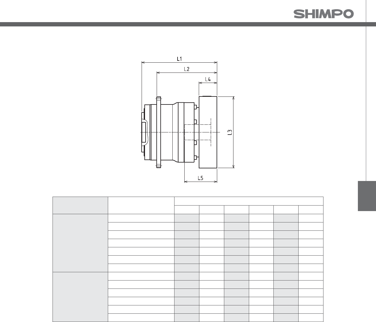
VRT
VRT- 2-Stage Adapter Dimensions
*1) Double reduction : /~ /
*2) Bushing will be inserted to adapt to motor shaft
Model Number **: Adapter Code 2-Stage
L1 L* L2 L3 L4 L5
VRT-285-□-□-48**
(Input shaft bore ≦ φ48)
KA 339 264 264 □180 75 118
KB•KC 319 264 244 □180 55 98
LA 319 264 244 □200 55 98
MA 319 264 244 □220 55 98
MB 339 264 264 □220 75 118
NA 339 264 264 □250 75 118
PA 339 264 264 □280 75 118
VRT-285-□-□-65**
(Input shaft bore ≦ φ65)
MA•MB•MC•MD -- -- -- -- -- --
NA•NC -- -- -- -- -- --
NB•ND -- -- -- -- -- --
PA -- -- -- -- -- --
PB -- -- -- -- -- --
QA•QB -- -- -- -- -- --
A more comprehensive adapter ange o ering can be found using the NIDECSHIMPO Online Selector Tool. The variety is constantly
expanding and being updated on the Selector Tool. If you have any questions or need any support, contact NIDECSHIMPO.
For an explanation on the Adapter Flange Code, please turn to page .

T
he NEV right-angle series is the ideal gearbox for simpler one-
directional servo motor applications where space and cost
take precedence. The performance and efficiency of the NEV out-
performs worm or helical gear options, so many machine builders
strongly consider this series, instead of settling for their old default
right-angle gearbox. Many times, our OEM customers are upgrading
from an induction motor and a helical or worm assembly because
their customer is requiring increased throughput and control. In this
type of sensitive situation, the NEV is a very price competitive op-
tion to help keep the OEMs equipment costs in check and meet the
improved functionality required.
The NEV has a lightweight aluminum frame with either a hollow or solid
shaft con guration at the output. The series can handle motors ranging
between w to . kW, and it achieves nominal output torque ratings
ranging between Nm to Nm. The di erent NEV frame sizes are avail-
able in ratios between : and :, and the gearbox can be provided in
special coatings, lubrication, and materials of construction that make it
ideal for applications in direct food-grade exposure or heavy washdown
intensive environments.
NEV-SERIES
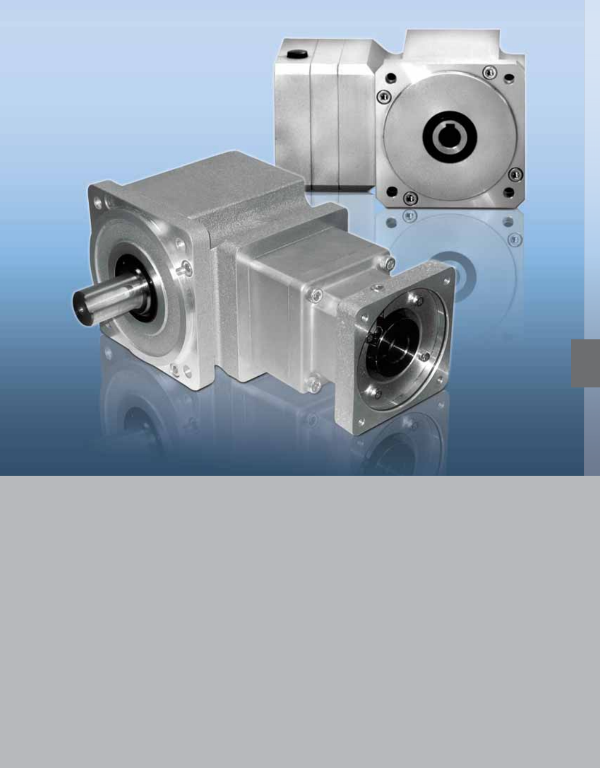
NEV-SERIES
■Hollow bore output option, provides a very compact footprint and cost-e ective
right-angle solution
■Quiet operation: Helical cut gears contribute to reduced vibration and noise
■High rigidity & torque: Rigidity and torque capacity are achieved by using uncaged
needle roller bearings
■Extremely light weight aluminum body to reduce excess weight from your equipment
■Maintenance-free: No need to replace the grease for the life of the unit. The gearbox
can be positioned in any orientation
NEV
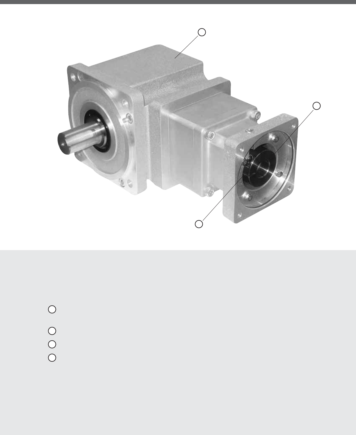
NEV-SERIES Right-angle shaft
NEV-Series Features
1 This space saving Right-angle gearbox utilizes a spiral bevel gear. Motor can be located at a degree
position from the reducer providing a more compact footprint
2 High rigidity and torque capacity are achieved by using uncaged needle roller bearings
3 Adapter-bushing connection enables a simple, e ective attachment to most servo motors
4 No leakage through the seal; and the high viscosity, anti-separation grease does not liquefy or migrate
away from the gears
4
1
3

NEV
NEV-Series Model Code
t$VTUPNNPUPSBUUBDINFOUEJNFOTJPOT
t'PPEHSBEFHSFBTFOFFEFEXIFOVOJUJTQMBDFEBCPWFBGPPEMJOF
t4UBJOMFTTTUFFMPVUQVUTIBGU
t$VTUPNSBUJPT
t$VTUPNPVUQVUT
t0VUQVUTIBGUESJMMFEBOEUBQQFE
ModicationsBushingsMotor AttachmentRatioFrameInputModel
1 2 3
4FF/PUFT#FMPX
Options & Modications Available
FNEV
Model
0SEFSJOH$PEF
/&7 3JHIU"OHMF
Ordering Code
/&7"'/&74'
1:505
1:9
09
1:51
15
1:72
27
1:54
45
1:57
75
1H 105:1
%PVCMF
3FEVDUJPO
5SJQMF
3FEVDUJPO
Frame Size
0SEFSJOH$PEF
#
$
D
&&'SBNF
#'SBNF
$'SBNF
%'SBNF
Adaptor Flange
Re-Threaded Hole
XJUI5$PEF
T
M4
M5
M6
M8
M10
M12
M5
M6
M4
M3
M10
4UBOEBSE
M8
Input
0SEFSJOH$PEF
"
4%FEJDBUFEXDMBNQIVC
"EBQUPS'MBOHF
Motor Attachment
#PMU$JSDMFPGNPUPSJONN
0SEFSJOH$PEF
440
540
640
060
360
760
070
570
090
590
890
001
511
621
031
541
941
561
200
130
/&."
115
/&."
70
75
90
95
/&."
100
46
60
63
45
200
/&."
145
/&."
561
Bushing
0SEFSJOH$PEF
0000
00__
/PODBUBMPH
EFEJDBUFECPSF
JONNTQFDJGZ
/P#VTIJOH
3FRVJSFE
0%NN*%NN
0801 8
0802 8 6.350
580803
6141401
814
14
14
14
14
14
14
14
1402
1403
1404
1405
11
9.525
1406
1407 12
1408 10
1409 9
5141410
11191901
14191902
16191903
9.52519
19
19
19
19
19
19
1904
12.7001905
1906
1907
1908
1909
1910
15.875
12
10
9
8
1424
24
24
24
24
24
24
24
2401
2402
2403
2404
2405
2406
2407
2408
16
19
12.700
15.875
22
19.050
11
6
6.350
12.700
Modications/Motor
Attachment Threaded Hole
0SEFSJOH$PEF
/&7"'IPMMPXPVUQVUTIBGU
*1OPQBJOUTUBOEBSEHSFBTF
'PPEHSBEFHSFBTFOPQBJOU*1
/&7"'TPMJEPVUQVUTIBGU
,FZMFTTPVUQVUTIBGU
3FUBQNPUPSBUUBDINFOUøBOHFPOFTJ[FMBSHFS
5ISPVHIIPMFPONPUPSBUUBDINFOUøBOHF
-BSHFSUISPVHIIPMFPONPUPSBUUBDINFOUøBOHF
'PPEHSBEFHSFBTF4UFFM*UQBJOU*1
4UFFM*UQBJOUTUBOEBSEHSFBTF*1
8IJUFFQPYZQBJOUTUBOEBSEHSFBTF*1
'PPEHSBEFHSFBTFXIJUFFQPYZQBJOU*1
1JMPUEJBNFUFSSFEVDFE
%FFQFSNPUPSBUUBDINFOUøBOHFBEETQBDFSQMBUF
4QFDJGZ
4UBOEBSE
000
5
6
7
*
'
G
4
8
X
T
H
-
#
R
"@
Notes on “Modi cations” Section of Code:
1) Feature 5, 6, or 7 would be entered in Box1 of the section of code.
2) Feature B or R would be entered in Box3 of the code.
3) Enter additional features in Box1, 2, 3 if available, organize in either numeric or alphabetical order.
4) If Box that is not utilized, enter a 0 ll the Boxes within the Modi cations section.

NEV-SERIES Right-angle shaft
NEV B-Frame 2-Stage Specifications
Frame Size B (78mm)
Stage 2-Stage
Ratio Units Note 5 9 15 27
Nominal Output Torque [Nm] -- 6 6 10 10
Maximum Acceleration Torque [Nm] -- 20 20 30 30
Emergency Stop Torque [Nm] -- 35 40 50 50
Nominal Input Speed [rpm] -- 3000
Maximum Input Speed [rpm] -- 6000
No Load Running Torque [Nm] -- 0.18
Permitted Radial Load [N] -- 1000 1200 1500 1800
Permitted Axial Load [N] -- 500 600 750 900
Moment of Inertia (≤Ø 8) [kgcm2] -- -- -- -- --
Moment of Inertia (≤ Ø14) [kgcm2] -- 0.275 0.110 0.059 0.146
E ciency [%] -- 85
Torsional Rigidity [Nm/arcmin] -- 0.4
Maximum Torsional Backlash [Arc-min] -- ≤ 30
Noise Level [dB] -- ≤ 73
Protection Class -- -- IP65
Ambient Temperature [°C] -- 0-40
Permitted Housing Temperature [°C] -- 90
Weight (Solid Output Shaft) [kg] -- 3.8
Weight (Hollow Output Shaft) [kg] -- 3.6
NEV B-Frame, 2-Stage Dimensions, Solid / Hollow Output Shaft Type Ratios: 5:1, 9:1, 15:1, 27:1
Adapter Unit Bolt Circle
LC
Pilot
LH
Square
LD
Tapping Bolt
LJ
Depth
Y
Length Plug
LK
Flange Depth
LCL LFLGML
B1 mm 45 30 42 M3x0.5 8 168.5 129.5 10 6 5 32
in 1.772 1.181 1.65 -- 0.31 6.634 5.098 0.39 0.24 0.20 1.26
B2 mm 46 30 42 M4X0.7 10 168.5 129.5 10 6 5 32
in 1.811 1.181 1.65 -- 0.39 6.634 5.098 0.39 0.24 0.20 1.26
B8 mm 46 30 42 M4X0.7 10 171.5 132.5 13 6 8 35
in 1.811 1.181 1.65 -- 0.39 6.752 5.217 0.51 0.24 0.31 1.38
B4 mm 60 50 60 M4X0.7 10 168.5 129.5 10 4 5 32
in 2.362 1.969 2.36 -- 0.39 6.634 5.098 0.39 0.16 0.20 1.26
B4 mm 70 50 60 M4X0.7 10 168.5 129.5 10 4 5 32
in 2.756 1.969 2.36 -- 0.39 6.634 5.098 0.39 0.16 0.20 1.26
B9 mm 70 50 60 M5X0.8 20 173.5 134.5 15 9 10 37
in 2.756 1.969 2.36 -- 0.79 6.831 5.295 0.59 0.35 0.39 1.46
B5 mm 66.68 38.100 58 M4X0.7 10 168.5 129.5 10 4 5 32
(NEMA23) in 2.625 1.500 2.28 -- 0.39 6.634 5.098 0.39 0.16 0.20 1.26
B5+Spacer mm 66.68 38.100 60 M5X0.8 -- 176.5 137.5 18 3 13 40
(NEMA23) in 2.625 1.500 2.36 -- -- 6.949 5.413 0.71 0.12 0.51 1.57
B6 mm 90 70 80 M5X0.8 12 168.5 129.5 10 4 5 32
in 3.543 2.756 3.15 -- 0.47 6.634 5.098 0.39 0.16 0.20 1.26
B7 mm 43.80 22 42 2-3.3 dia. -- 170.5 131.5 12 4 7 34
(NEMA17) in 1.724 0.866 1.65 2-0.13 dia. -- 6.713 5.177 0.47 0.16 0.28 1.34
B10 mm 63 40 58 M4X0.7 10 168.5 129.5 10 4 5 32
in 2.480 1.575 2.28 -- 0.39 6.634 5.098 0.39 0.16 0.20 1.26
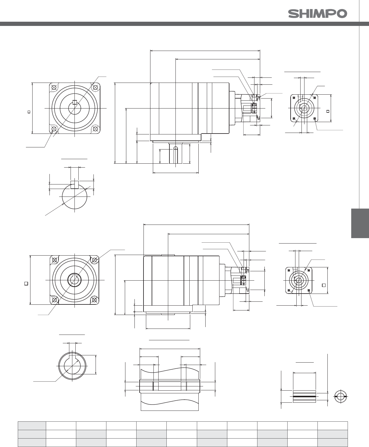
NEV
Bushings
Bushing 1401 1402 1403 1404 1405 1406 1407 1408 1409 1410
Inside 6 8 11 6.350 9.525 12.700 12 10 9 5
Diameter 0.236 0.315 0.433 0.250 0.375 0.500 0.472 0.394 0.354 0.197
NEV B-Frame (mm) 2-Stage Dimensions Ratios: 5:1, 9:1, 15:1, 27:1
Solid Output Shaft Type
Hollow Output Shaft Type
Motor Attachment
4-LJxPitch
Depth Y
M4
Clamp Bolt
Access Plug
O-Ring
Ø19(h6)
6
6
5
L
CL
124
85
1035
3
30
22
Ø70(h7)
Ø14
ML
LG
ØLH
LD
LF
LK 9
ØLC
Output Shaft
78
Ø
90
4-
Ø
6.5
4-Ø6.5
168.5
129.5
96
55
10
3
Ø
70(h7)
Ø
14
32
Ø
LH
LD
LF
10 9
Ø
LC
Ø
13
(h8)
5
15
Output Hollow
Ø
13
13
Ø
Detail of Output Hollow
96
30 30
22 22
78
Ø90
5
5
Motor Attachment
4-LJxPitch
Depth Y
M4
Clamp Bolt
Access Plug
Bushings
Inside Dia.
14
Ø
26

NEV-SERIES Right-angle shaft
NEV B-Frame 3-Stage Specifications
Frame Size B (78mm)
Stage 3-Stage
Ratio Units Note 45 75 105
Nominal Output Torque [Nm] -- 10 15 15
Maximum Acceleration Torque [Nm] -- 30 30 30
Emergency Stop Torque [Nm] -- 50 50 50
Nominal Input Speed [rpm] -- 3000
Maximum Input Speed [rpm] -- 6000
No Load Running Torque [Nm] -- 0.109
Permitted Radial Load [N] -- 1800 1800 1800
Permitted Axial Load [N] -- 900 900 900
Moment of Inertia (≤Ø 8) [kgcm2] -- 0.091 0.083 0.078
Moment of Inertia (≤ Ø14) [kgcm2] -- -- -- --
E ciency [%] -- 80
Torsional Rigidity [Nm/arcmin] -- 0.4
Maximum Torsional Backlash [Arc-min] -- ≤ 30
Noise Level [dB] -- ≤ 63
Protection Class -- -- IP65
Ambient Temperature [°C] -- 0-40
Permitted Housing Temperature [°C] -- 90
Weight (Solid Output Shaft) [kg] -- 3.9
Weight (Hollow Output Shaft) [kg] -- 3.7
NEV B-Frame, 3-Stage Dimensions, Solid / Hollow Output Shaft Type Ratios: 45:1, 75:1, 105:1
Adapter Unit Bolt Circle
LC
Pilot
LH
Square
LD
Tapping Bolt
LJ
Depth
Y
Length Plug
LK
Flange Depth
LCL LFLGML
B1 mm 45 30 42 M3x0.5 8 174 135 10 6 5 32
in 1.772 1.181 1.65 -- 0.31 6.850 5.315 0.39 0.24 0.20 1.26
B2 mm 46 30 42 M4X0.7 10 174 135 10 6 5 32
in 1.811 1.181 1.65 -- 0.39 6.850 5.315 0.39 0.24 0.20 1.26
B8 mm 46 30 42 M4X0.7 10 177 138 13 6 8 35
in 1.811 1.181 1.65 -- 0.39 6.969 5.433 0.51 0.24 0.31 1.38
B4 mm 60 50 60 M4X0.7 10 174 135 10 4 5 32
in 2.362 1.969 2.36 -- 0.39 6.850 5.315 0.39 0.16 0.20 1.26
B4 mm 70 50 60 M4X0.7 10 174 135 10 4 5 32
in 2.756 1.969 2.36 -- 0.39 6.850 5.315 0.39 0.16 0.20 1.26
B9 mm 70 50 60 M5X0.8 20 179 140 15 9 10 37
in 2.756 1.969 2.36 -- 0.79 7.047 5.512 0.59 0.35 0.39 1.46
B5 mm 66.68 38.100 58 M4X0.7 10 174 135 10 4 5 32
(NEMA23) in 2.625 1.500 2.28 -- 0.39 6.850 5.315 0.39 0.16 0.20 1.26
B5+Spacer mm 66.68 38.100 60 M5X0.8 12 182 143 18 3 13 40
(NEMA23) in 2.625 1.500 2.36 -- 0.47 7.165 5.630 0.71 0.12 0.51 1.57
B6 mm 90 70 80 M5X0.8 12 174 135 10 4 5 32
in 3.543 2.756 3.15 -- 0.47 6.850 5.315 0.39 0.16 0.20 1.26
B7 mm 43.80 22 42 2-3.3 dia. -- 176 137 12 4 7 34
(NEMA17) in 1.724 0.866 1.65 2-0.13 dia. -- 6.929 5.394 0.47 0.16 0.28 1.34
B10 mm 63 40 58 M4X0.7 10 174 135 10 4 5 32
in 2.480 1.575 2.28 -- 0.39 6.850 5.315 0.39 0.16 0.20 1.26

NEV
NEV B-Frame (mm) 3-Stage Dimensions Ratios: 45:1, 75:1, 105:1
Bushings
Solid Output Shaft Type
Hollow Output Shaft Type
Bushing 0801 0802 0803
Inside 6 6.350 5
Diameter 0.236 0.250 0.197
Ø19(h6)
6
6
5
L
CL
124
85
1035
3
30
22
Ø8
ML
LG
ØLH
LD
LF
LK 9
ØLC
Output Shaft
78
Ø
90
Motor Attachment
4-LJxPitch
Depth Y
M4
Clamp Bolt
Access Plug
O-Ring
4-Ø6.5
Ø70(h7)
96
55
105
3
Ø70(h7)
Ø8
ML
LG
ØLH
LD
9
ØLC
Ø13(H8)
5
15
Output Hollow
Ø13
Ø13
Detail of Output Hollow
96
30 30
22 22
78
Ø90
Motor Attachment
4-LJxPitch
Depth Y
4-Ø6.5
L
CL
LF
LK
M4
Clamp Bolt
Access Plug
O-Ring
Inside Dia.
Ø8
21
Bushing

NEV-SERIES Right-angle shaft
NEV C-Frame 2-Stage Specifications
Frame Size C (90mm)
Stage 2-Stage
Ratio Units Note 5 9 15 27
Nominal Output Torque [Nm] -- 15 20 20 30
Maximum Acceleration Torque [Nm] -- 30 35 40 40
Emergency Stop Torque [Nm] -- 50 50 60 75
Nominal Input Speed [rpm] -- 3000
Maximum Input Speed [rpm] -- 6000
No Load Running Torque [Nm] -- 0.3
Permitted Radial Load [N] -- 1000 1500 1800 1800
Permitted Axial Load [N] -- 500 750 900 900
Moment of Inertia (≤Ø14) [kgcm2] -- -- -- -- --
Moment of Inertia (≤ Ø19) [kgcm2] -- 0.806 0.744 0.415 0.585
E ciency [%] -- 85
Torsional Rigidity [Nm/arcmin] -- 1.0
Maximum Torsional Backlash [Arc-min] -- ≤ 30
Noise Level [dB] -- ≤ 73
Protection Class -- -- IP65
Ambient Temperature [°C] -- 0-40
Permitted Housing Temperature [°C] -- 90
Weight (Solid Output Shaft) [kg] -- 4.1
Weight (Hollow Output Shaft) [kg] -- 4.0
Adapter Unit Bolt Circle
LC
Pilot
LH
Square
LD
Tapping Bolt
LJ
Depth
Y
Length Plug
LK
Flange Depth
LCL LFLGML
C1 mm 60 50 60 M4x0.7 10 206.5 161.5 11 4 5 42
in 2.362 1.969 2.36 -- 0.39 8.130 6.358 0.43 0.16 0.20 1.65
C1 mm 70 50 60 M4x0.7 10 206.5 161.5 11 4 5 42
in 2.756 1.969 2.36 -- 0.39 8.130 6.358 0.43 0.16 0.20 1.65
C7 mm 70 50 60 M5x0.8 12 210.5 165.5 15 6 9 46
in 2.756 1.969 2.36 -- 0.47 8.287 6.516 0.59 0.24 0.35 1.81
C2 mm 90 70 80 M5X0.8 12 206.5 161.5 11 4 5 42
in 3.543 2.756 3.15 -- 0.47 8.130 6.358 0.43 0.16 0.20 1.65
C8 mm 90 70 80 M6X1.0 21 211.5 166.5 16 9 10 47
in 3.543 2.756 3.15 -- 0.83 8.327 6.555 0.63 0.35 0.39 1.85
C3 mm 100 80 86 M6X1.0 16 206.5 161.5 11 4 5 42
in 3.937 3.150 3.39 -- 0.63 8.130 6.358 0.43 0.16 0.20 1.65
C4 mm 98.43 73.025 83 M5X0.8 12 206.5 161.5 11 4 5 42
(NEMA34) in 3.875 2.875 3.27 -- 0.47 8.130 6.358 0.43 0.16 0.20 1.65
C4+Spacer mm 98.43 73.025 83 M5X0.8 12 214.5 169.5 19 3 13 50
(NEMA34) in 3.875 2.875 3.27 -- 0.47 8.445 6.673 0.75 0.12 0.51 1.97
C5 mm 75 60 67 M5X0.8 12 206.5 161.5 11 4 5 42
in 2.953 2.362 2.64 -- 0.47 8.130 6.358 0.43 0.16 0.20 1.65
C6 mm 115 95 100 M6X1.0 16 206.5 161.5 11 4 5 42
in 4.528 3.740 3.94 -- 0.63 8.130 6.358 0.43 0.16 0.20 1.65
C9 mm 66.68 38.100 60 M4x0.7 10 206.5 161.5 11 4 5 42
(NEMA23) in 2.625 1.500 2.36 -- 0.39 8.130 6.358 0.43 0.16 0.20 1.65
C14 mm 66.68 38.100 60 M5x0.8 -- 214.5 169.5 18 11 13 50
in 2.625 1.500 2.36 -- -- 8.445 6.673 0.71 0.43 0.51 1.97
NEV C-Frame, 2-Stage Dimensions, Solid / Hollow Output Shaft Type Ratios: 5:1, 9:1, 15:1, 27:1

NEV
Adapter Unit Bolt Circle
LC
Pilot
LH
Square
LD
Tapping Bolt
LJ
Depth
Y
Length Plug
LK
Flange Depth
LCL LFLGML
C10 mm 63 40 60 M4x0.7 10 206.5 161.5 11 4 5 42
in 2.480 1.575 2.36 -- 0.39 8.130 6.358 0.43 0.16 0.20 1.65
C11 mm 95 80 86 M6x1.0 -- 206.5 161.5 11 4 5 42
in 3.740 3.150 3.39 -- -- 8.130 6.358 0.43 0.16 0.20 1.65
NEV C-Frame, 2-Stage Dimensions, Solid / Hollow Output Shaft Type Ratios: 5:1, 9:1, 15:1, 27:1
NEV C-Frame (mm) 2-Stage Dimensions Ratios: 5:1, 9:1, 15:1, 27:1
Bushings
Solid Output Shaft Type
Hollow Output Shaft Type
Bushing 1901 1902 1903 1904 1905 1906 1907 1908 1909 1910 1911
Inside 11 14 16 9.525 12.700 15.875 12 10 9 8 6.350
Diameter 0.433 0.551 0.630 0.375 0.500 0.625 0.472 0.394 0.354 0.315 0.250
4-LJxPitch
Depth Y
M4
Clamp Bolt
Access Plug Motor Attachment
O-Ring
Ø19
ML
LG
ØLH
LD
LF
LK 13.5
ØLC
90
CL
L
87
35
127
22
3
Ø100
26
6
21.5
6
Output Shaft
4-Ø6.5
Ø
80(h7)
30
Ø19h6
11
4-Ø6.5
Ø19
ML
LG
ØLH
LD
LF
LK 13.5
ØLC
90
Ø80(h7)
CL
L
57
11
5
99
3
Ø100
5
19
Output Hollow
Ø17(H8)
17
Ø
Detail of Output Hollow
99
30 30
22 22
4-LJxPitch
Depth Y
M4
Clamp Bolt
Access Plug Motor Attachment
O-Ring
Ø
17
Inside Dia.
Ø19
36
Bushing

NEV-SERIES Right-angle shaft
NEV C-Frame 3-Stage Specifications
Frame Size C (90mm)
Stage 3-Stage
Ratio Units Note 45 75 105
Nominal Output Torque [Nm] -- 30 30 30
Maximum Acceleration Torque [Nm] -- 40 40 40
Emergency Stop Torque [Nm] -- 75 75 75
Nominal Input Speed [rpm] -- 3000
Maximum Input Speed [rpm] -- 6000
No Load Running Torque [Nm] -- 0.205
Permitted Radial Load [N] -- 1800 1800 1800
Permitted Axial Load [N] -- 900 900 900
Moment of Inertia (≤Ø14) [kgcm2] -- 0.794 0.690 0.590
Moment of Inertia (≤ Ø19) [kgcm2] -- -- -- --
E ciency [%] -- 80
Torsional Rigidity [Nm/arcmin] -- 1.0
Maximum Torsional Backlash [Arc-min] -- ≤ 30
Noise Level [dB] -- ≤ 63
Protection Class -- -- IP65
Ambient Temperature [°C] -- 0-40
Permitted Housing Temperature [°C] -- 90
Weight (Solid Output Shaft) [kg] -- 4.3
Weight (Hollow Output Shaft) [kg] -- 4.2
Adapter Unit Bolt Circle
LC
Pilot
LH
Square
LD
Tapping Bolt
LJ
Depth
Y
Length Plug
LK
Flange Depth
LCL LFLGML
C1 mm 60 50 60 M4x0.7 10 209 164 11 4 5 42
in 2.362 1.969 2.36 -- 0.39 8.228 6.457 0.43 0.16 0.20 1.65
C1 mm 70 50 60 M4x0.7 10 209 164 11 4 5 42
in 2.756 1.969 2.36 -- 0.39 8.228 6.457 0.43 0.16 0.20 1.65
C7 mm 70 50 60 M5x0.8 12 213 168 15 6 9 46
in 2.756 1.969 2.36 -- 0.47 8.386 6.614 0.59 0.24 0.35 1.81
C2 mm 90 70 80 M5X0.8 12 209 164 11 4 5 42
in 3.543 2.756 3.15 -- 0.47 8.228 6.457 0.43 0.16 0.20 1.65
C8 mm 90 70 80 M6X1.0 21 214 169 16 9 10 47
in 3.543 2.756 3.15 -- 0.83 8.425 6.654 0.63 0.35 0.39 1.85
C3 mm 100 80 86 M6X1.0 16 209 164 11 4 5 42
in 3.937 3.150 3.39 -- 0.63 8.228 6.457 0.43 0.16 0.20 1.65
C4 mm 98.43 73.025 83 M5X0.8 12 209 164 11 4 5 42
(NEMA34) in 3.875 2.875 3.27 -- 0.47 8.228 6.457 0.43 0.16 0.20 1.65
C4+Spacer mm 98.43 73.025 83 M5X0.8 12 217 172 19 3 13 50
(NEMA34) in 3.875 2.875 3.27 -- 0.47 8.543 6.772 0.75 0.12 0.51 1.97
C5 mm 75 60 67 M5X0.8 12 209 164 11 4 5 42
in 2.953 2.362 2.64 -- 0.47 8.228 6.457 0.43 0.16 0.20 1.65
C6 mm 115 95 100 M6X1.0 16 209 164 11 4 5 42
in 4.528 3.740 3.94 -- 0.63 8.228 6.457 0.43 0.16 0.20 1.65
C9 mm 66.68 38.100 60 M4x0.7 10 209 164 11 4 5 42
(NEMA23) in 2.625 1.500 2.36 -- 0.39 8.228 6.457 0.43 0.16 0.20 1.65
C14 mm 66.68 38.100 60 M5x0.8 12 217 172 18 11 13 50
in 2.625 1.500 2.36 -- 0.47 8.543 6.772 0.71 0.43 0.51 1.97
NEV C-Frame, 3-Stage Dimensions, Solid / Hollow Output Shaft Type Ratios: 45:1, 75:1, 105:1

NEV
Adapter Unit Bolt Circle
LC
Pilot
LH
Square
LD
Tapping Bolt
LJ
Depth
Y
Length Plug
LK
Flange Depth
LCL LFLGML
C10 mm 63 40 60 M4x0.7 10 209 164 11 4 5 42
in 2.480 1.575 2.36 -- 0.39 8.228 6.457 0.43 0.16 0.20 1.65
C11 mm 95 80 86 M6x1.0 - 209 164 11 4 5 42
in 3.740 3.150 3.39 -- - 8.228 6.457 0.43 0.16 0.20 1.65
NEV C-Frame, 3-Stage Dimensions, Solid / Hollow Output Shaft Type Ratios: 45:1, 75:1, 105:1
NEV C-Frame (mm) 3-Stage Dimensions Ratios: 45:1, 75:1, 105:1
Bushings
Solid Output Shaft Type
Hollow Output Shaft Type
Bushing 1401 1402 1403 1404 1405 1406 1407 1408 1409 1410
Inside 6 8 11 6.350 9.525 12.700 12 10 9 5
Diameter 0.236 0.315 0.433 0.250 0.375 0.500 0.472 0.394 0.354 0.197
4-LJxPitch
Depth Y
M4
Clamp Bolt
Access Plug Motor Attachment
O-Ring
Ø14
ML
LG
ØLH
LD
LF
LK 13.5
ØLC
90
CL
L
87
35
127
22
3
Ø100
6
21.5
6
Output Shaft
4-Ø6.5
Ø
80(h7)
30
Ø19h6
11
4-Ø6.5
Ø14
ML
LG
ØLH
LD
LF
LK 13.5
ØLC
90
Ø80(h7)
CL
L
57
11
5
99
3
Ø100
5
19
Output Hollow
Ø17(H8)
17
Ø
Detail of Output Hollow
99
30 30
22 22
4-LJxPitch
Depth Y
M4
Clamp Bolt
Access Plug Motor Attachment
O-Ring
Ø
17
Inside Dia.
Ø19
36
Bushing

NEV-SERIES Right-angle shaft
NEV D-Frame 2-Stage Specifications
Frame Size D (115mm)
Stage 2-Stage
Ratio Units Note 5 9 15 27
Nominal Output Torque [Nm] -- 25 25 25 40
Maximum Acceleration Torque [Nm] -- 55 75 75 80
Emergency Stop Torque [Nm] -- 100 140 140 180
Nominal Input Speed [rpm] -- 3000
Maximum Input Speed [rpm] -- 6000
No Load Running Torque [Nm] -- 0.45
Permitted Radial Load [N] -- 2200 2200 2600 2600
Permitted Axial Load [N] -- 1100 1100 1300 1300
Moment of Inertia (≤Ø14) [kgcm2] -- -- -- -- --
Moment of Inertia (≤ Ø19) [kgcm2] -- 1.502 1.254 0.464 0.720
E ciency [%] -- 85
Torsional Rigidity [Nm/arcmin] -- 1.2 1.5 1.5 1.5
Maximum Torsional Backlash [Arc-min] -- ≤ 30
Noise Level [dB] -- ≤ 73
Protection Class -- -- IP65
Ambient Temperature [°C] -- 0-40
Permitted Housing Temperature [°C] -- 90
Weight (Solid Output Shaft) [kg] -- 7.1
Weight (Hollow Output Shaft) [kg] -- 6.7
Adapter Unit Bolt Circle
LC
Pilot
LH
Square
LD
Tapping Bolt
LJ
Depth
Y
Length Plug
LK
Flange Depth
LCL LFLGML
D1 mm 60 50 60 M4x0.7 10 234 176.5 11 4 5 42
in 2.362 1.969 2.36 -- 0.39 9.213 6.949 0.43 0.16 0.20 1.65
D1 mm 70 50 60 M4x0.7 10 234 176.5 11 4 5 42
in 2.756 1.969 2.36 -- 0.39 9.213 6.949 0.43 0.16 0.20 1.65
D7 mm 70 50 60 M5x0.8 12 238 180.5 15 6 9 46
in 2.756 1.969 2.36 -- 0.47 9.370 7.106 0.59 0.24 0.35 1.81
D2 mm 90 70 80 M5X0.8 12 234 176.5 11 4 5 42
in 3.543 2.756 3.15 -- 0.47 9.213 6.949 0.43 0.16 0.20 1.65
D8 mm 90 70 80 M6X1.0 21 239 181.5 16 9 10 47
in 3.543 2.756 3.15 -- 0.83 9.409 7.146 0.63 0.35 0.39 1.85
D3 mm 100 80 86 M6X1.0 16 234 176.5 11 4 5 42
in 3.937 3.150 3.39 -- 0.63 9.213 6.949 0.43 0.16 0.20 1.65
D4 mm 98.43 73.025 83 M5X0.8 12 234 176.5 11 4 5 42
(NEMA34) in 3.875 2.875 3.27 -- 0.47 9.213 6.949 0.43 0.16 0.20 1.65
D4+Spacer mm 98.43 73.025 83 M5X0.8 12 242 184.5 19 3 13 50
(NEMA34) in 3.875 2.875 3.27 -- 0.47 9.528 7.264 0.75 0.12 0.51 1.97
D5 mm 75 60 67 M5X0.8 12 234 176.5 11 4 5 42
in 2.953 2.362 2.64 -- 0.47 9.213 6.949 0.43 0.16 0.20 1.65
D6 mm 115 95 100 M6X1.0 16 234 176.5 11 4 5 42
in 4.528 3.740 3.94 -- 0.63 9.213 6.949 0.43 0.16 0.20 1.65
D9 mm 66.68 38.100 60 M4X0.7 10 234 176.5 11 4 5 42
(NEMA23) in 2.625 1.500 2.36 -- 0.39 9.213 6.949 0.43 0.16 0.20 1.65
D14 mm 66.68 38.100 60 M5X0.8 - 242 184.5 18 11 13 50
in 2.625 1.500 2.36 -- - 9.528 7.264 0.71 0.43 0.51 1.97
NEV D-Frame, 2-Stage Dimensions, Solid / Hollow Output Shaft Type Ratios: 5:1, 9:1, 15:1, 27:1

NEV
NEV D-Frame, 2-Stage Dimensions, Solid / Hollow Output Shaft Type Ratios: 5:1, 9:1, 15:1, 27:1
Adapter Unit Bolt Circle
LC
Pilot
LH
Square
LD
Tapping Bolt
LJ
Depth
Y
Length Plug
LK
Flange Depth
LCL LFLGML
D10 mm 63 40 60 M4x0.7 10 234 176.5 11 4 5 42
in 2.480 1.575 2.36 -- 0.39 9.213 6.949 0.43 0.16 0.20 1.65
D11 mm 95 80 86 M6x1.0 16 234 176.5 11 4 5 42
in 3.740 3.150 3.39 -- 0.63 9.213 6.949 0.43 0.16 0.20 1.65
Bushing 1901 1902 1903 1904 1905 1906 1907 1908 1909 1910 1911
Inside 11 14 16 9.525 12.700 15.875 12 10 9 8 6.350
Diameter 0.433 0.551 0.630 0.375 0.500 0.625 0.472 0.394 0.354 0.315 0.250
Bushings
L
CL
164
114
1448
5
40
30
Ø110(h7)
Ø19
ML
LG
ØLH
LD
LF
LK 13.5
ØLC
Ø24(h6)
8
7
4
Output Shaft
115
Ø130
4-Ø8.5
MOTOR ATTACHMENT
4-LJxPitch
Depth Y
M4
Clamp Bolt
Access Plug
O-Ring
NEV D-Frame (mm) 2-Stage Dimensions Ratios: 5:1, 9:1, 15:1, 27:1
Solid Output Shaft Type
Hollow Output Shaft Type L
CL
127
74
148
5
Ø110(h7)
Ø19
ML
LG
LH
LF
LK 13.5
ØLC
115
Ø130
8
27
Output Hollow Detail of Output Hollow
Ø24
Ø24
127
45 45
22 22
Ø24(h8)
4-Ø8.5
MOTOR ATTACHMENT
4-LJxPitch
Depth Y
M4
Clamp Bolt
Access Plug
O-Ring
LD
Inside Dia.
Ø19
36
Bushing

NEV-SERIES Right-angle shaft
NEV D-Frame 3-Stage Specifications
Frame Size D (115mm)
Stage 3-Stage
Ratio Units Note 45 75 105
Nominal Output Torque [Nm] -- 45 50 50
Maximum Acceleration Torque [Nm] -- 80 80 80
Emergency Stop Torque [Nm] -- 180 180 180
Nominal Input Speed [rpm] -- 3000
Maximum Input Speed [rpm] -- 6000
No Load Running Torque [Nm] -- 0.355
Permitted Radial Load [N] -- 2600 2600 2600
Permitted Axial Load [N] -- 1300 1300 1300
Moment of Inertia (≤Ø14) [kgcm2] -- 0.806 0.694 0.648
Moment of Inertia (≤ Ø19) [kgcm2] -- -- -- --
E ciency [%] -- 80
Torsional Rigidity [Nm/arcmin] -- 1.5
Maximum Torsional Backlash [Arc-min] -- ≤ 30
Noise Level [dB] -- ≤ 67
Protection Class -- -- IP65
Ambient Temperature [°C] -- 0-40
Permitted Housing Temperature [°C] -- 90
Weight (Solid Output Shaft) [kg] -- 7.3
Weight (Hollow Output Shaft) [kg] -- 6.9
NEV D-Frame, 3-Stage Dimensions, Solid / Hollow Output Shaft Type Ratios: 45:1, 75:1, 105:1
Adapter Unit Bolt Circle
LC
Pilot
LH
Square
LD
Tapping Bolt
LJ
Depth
Y
Length Plug
LK
Flange Depth
LCL LFLGML
D1 mm 60 50 60 M4x0.7 10 236.5 179 11 4 5 42
in 2.362 1.969 2.36 -- 0.39 9.311 7.047 0.43 0.16 0.20 1.65
D1 mm 70 50 60 M4x0.7 10 236.5 179 11 4 5 42
in 2.756 1.969 2.36 -- 0.39 9.311 7.047 0.43 0.16 0.20 1.65
D7 mm 70 50 60 M5x0.8 12 240.5 183 15 6 9 46
in 2.756 1.969 2.36 -- 0.47 9.469 7.205 0.59 0.24 0.35 1.81
D2 mm 90 70 80 M5X0.8 12 236.5 179 11 4 5 42
in 3.543 2.756 3.15 -- 0.47 9.311 7.047 0.43 0.16 0.20 1.65
D8 mm 90 70 80 M6X1.0 21 241.5 184 16 9 10 47
in 3.543 2.756 3.15 -- 0.83 9.508 7.244 0.63 0.35 0.39 1.85
D3 mm 100 80 86 M6X1.0 16 236.5 179 11 4 5 42
in 3.937 3.150 3.39 -- 0.63 9.311 7.047 0.43 0.16 0.20 1.65
D4 mm 98.43 73.025 83 M5X0.8 12 236.5 179 11 4 5 42
(NEMA34) in 3.875 2.875 3.27 -- 0.47 9.311 7.047 0.43 0.16 0.20 1.65
D4+Spacer mm 98.43 73.025 83 M5X0.8 12 244.5 187 19 3 13 50
(NEMA34) in 3.875 2.875 3.27 -- 0.47 9.626 7.362 0.75 0.12 0.51 1.97
D5 mm 75 60 67 M5X0.8 12 236.5 179 11 4 5 42
in 2.953 2.362 2.64 -- 0.47 9.311 7.047 0.43 0.16 0.20 1.65
D6 mm 115 95 100 M6X1.0 16 236.5 179 11 4 5 42
in 4.528 3.740 3.94 -- 0.63 9.311 7.047 0.43 0.16 0.20 1.65
D9 mm 66.68 38.100 60 M4X0.7 10 236.5 179 11 4 5 42
(NEMA23) in 2.625 1.500 2.36 -- 0.39 9.311 7.047 0.43 0.16 0.20 1.65
D14 mm 66.68 38.100 60 M5X0.8 12 244.5 187 18 11 13 50
in 2.625 1.500 2.36 -- 0.47 9.626 7.362 0.71 0.43 0.51 1.97

NEV
NEV D-Frame, 3-Stage Dimensions, Solid / Hollow Output Shaft Type Ratios: 45:1, 75:1, 105:1
Bushings
Adapter Unit Bolt Circle
LC
Pilot
LH
Square
LD
Tapping Bolt
LJ
Depth
Y
Length Plug
LK
Flange Depth
LCL LFLGML
D10 mm 63 40 60 M4x0.7 10 236.5 179 11 4 5 42
in 2.480 1.575 2.36 -- 0.39 9.311 7.047 0.43 0.16 0.20 1.65
D11 mm 95 80 86 M6x1.0 16 236.5 179 11 4 5 42
in 3.740 3.150 3.39 -- 0.63 9.311 7.047 0.43 0.16 0.20 1.65
Bushing 1401 1402 1403 1404 1405 1406 1407 1408 1409 1410
Inside 6 8 11 6.350 9.525 12.700 12 10 9 5
Diameter 0.236 0.315 0.433 0.250 0.375 0.500 0.472 0.394 0.354 0.197
NEV D-Frame (mm) 3-Stage Dimensions Ratios: 45:1, 75:1, 105:1
Solid Output Shaft Type
Hollow Output Shaft Type
L
CL
164
114
48
5
30
Ø110(h7)
Ø14
ML
LG
ØLH
LD
LF
LK 13.5
ØLC
Ø24(h6)
8
7
4
Output Shaft
115
Ø130
MOTOR ATTACHMENT
4-LJxPitch
Depth Y
M4
Clamp Bolt
Access Plug
4-Ø8.5
14
40
O-Ring
Output Hollow Detail of Output Hollow
Ø24
Ø24
127
45 45
22 22
Ø24(H8)
L
CL
74
148
5
Ø110(h7)
ML
LG
LH
LF
LK
M4
Clamp Bolt
Access Plug
O-Ring
Ø14
LD
13.5
ØLC
MOTOR ATTACHMENT
4-LJxPitch
Depth Y
27
115
Ø130
4-Ø8.5
127
8
Bushing
Inside Dia.
Ø14
26

NEV-SERIES Right-angle shaft
NEV E-Frame 2-Stage Specifications
Frame Size E (145mm)
Stage 2-Stage
Ratio Units Note 5 9 15 27
Nominal Output Torque [Nm] -- 50 50 55 60
Maximum Acceleration Torque [Nm] -- 100 140 140 180
Emergency Stop Torque [Nm] -- 250 250 250 300
Nominal Input Speed [rpm] -- 3000
Maximum Input Speed [rpm] -- 6000
No Load Running Torque [Nm] -- 1.21
Permitted Radial Load [N] -- 3000 3000 3000 4000
Permitted Axial Load [N] -- 1500 1500 1500 2000
Moment of Inertia (≤Ø19) [kgcm2] -- -- -- -- --
Moment of Inertia (≤ Ø24) [kgcm2] -- 3.559 2.940 1.193 2.044
E ciency [%] -- 85
Torsional Rigidity [Nm/arcmin] -- 3.2 4.0 4.0 4.0
Maximum Torsional Backlash [Arc-min] -- ≤ 30
Noise Level [dB] -- ≤ 74
Protection Class -- -- IP65
Ambient Temperature [°C] -- 0-40
Permitted Housing Temperature [°C] -- 90
Weight (Solid Output Shaft) [kg] -- 11.0
Weight (Hollow Output Shaft) [kg] -- 10.0
NEV E-Frame, 2-Stage Dimensions, Solid / Hollow Output Shaft Type Ratios: 5:1, 9:1, 15:1, 27:1
Adapter Unit Bolt Circle
LC
Pilot
LH
Square
LD
Tapping Bolt
LJ
Depth
Y
Length Plug
LK
Flange Depth
L CL LF LG ML
E1 mm 115 95 100 M6x1.0 15 282.5 210 15 4 7 57
in 4.528 3.740 3.94 -- 0.59 11.122 8.268 0.59 0.16 0.28 2.24
E2 mm 90 70 80 M5x0.8 12 282.5 210 14 4 7 57
in 3.543 2.756 3.15 -- 0.47 11.122 8.268 0.55 0.16 0.28 2.24
E7 mm 90 70 80 M6x1.0 15 285.5 213 17 6 10 60
in 3.543 2.756 3.15 -- 0.59 11.240 8.386 0.67 0.24 0.39 2.36
E3 mm 100 80 90 M6x1.0 15 282.5 210 14 4 7 57
in 3.937 3.150 3.54 -- 0.59 11.122 8.268 0.55 0.16 0.28 2.24
E4 mm 125.73 55.563 108 M6x1.0 15 282.5 210 15 5 7 57
(NEMA42) in 4.950 2.188 4.25 -- 0.59 11.122 8.268 0.59 0.20 0.28 2.24
E5 mm 145 110 130 M8X1.25 16 285.5 213 18 6 10 60
in 5.709 4.331 5.12 -- 0.63 11.240 8.386 0.71 0.24 0.39 2.36
E6 mm 130 110 115 M8X1.25 16 282.5 210 15 6 7 60
in 5.118 4.331 4.53 -- 0.63 11.122 8.268 0.59 0.24 0.28 2.36
E11 mm 98.43 73.025 90 M5x0.8 12 282.5 210 14 4 7 57
(NEMA34) in 3.875 2.875 3.54 -- 0.47 11.122 8.268 0.55 0.16 0.28 2.24
E12 mm 149.22 114.300 130 -- - 285.5 213 18 6 10 60
(NEMA56) in 5.875 4.500 5.12 3/8UNC-16 - 11.240 8.386 0.71 0.24 0.39 2.36
E13 mm 66.7 38.1 80 M4x0.7 10 282.5 210 14 4 7 57
in 2.626 1.500 3.15 -- 0.39 11.122 8.268 0.55 0.16 0.28 2.24
E14 mm 70 50 80 M4x0.7 10 282.5 210 14 4 7 57
in 2.756 1.969 3.15 -- 0.39 11.122 8.268 0.55 0.16 0.28 2.24
E15 mm 75 60 80 M5x0.8 12 282.5 210 14 4 7 57
in 2.953 2.362 3.15 -- 0.47 11.122 8.268 0.55 0.16 0.28 2.24

NEV
Bushings
Bushing 2401 2402 2403 2404 2405 2406 2407 2408
Inside 14 16 19 12.700 15.875 22 19.050 11
Diameter 0.551 0.630 0.748 0.500 0.625 0.866 0.750 0.433
NEV E-Frame (mm) 2-Stage Dimensions Ratios: 5:1, 9:1, 15:1, 27:1
Output Hollow
10
35
Ø32(h8)
Detail of Output Hollow
Ø32
Ø32
131
50 50
22 22
Ø24
ML
LG
ØLH
LD
LF
LK 15
ØLC
Ø130(h7)
L
CL
131
Ø165
78
145
5
14
8
4-LJxPitch
Depth Y
M4
Clamp Bolt
Access Plug
Motor Attachment
4-Ø11
O-Ring
Inside Dia.
Ø24
48
Bushing
Solid Output Shaft Type
Hollow Output Shaft Type
Ø24
ML
LG
ØLH
LF
LK
Ø130(h7)
L
CL
183
Ø165
133
145
5
1463
Output Shaft
10
5
8
Ø32(h6)
52
55
4-LJxPitch
Depth Y
M4
Clamp Bolt
Access Plug
Motor Attachment
4-Ø11
O-Ring
45
LD
15
ØLC

NEV-SERIES Right-angle shaft
NEV E-Frame 3-Stage Specifications
Frame Size E (145mm)
Stage 3-Stage
Ratio Units Note 45 75 105
Nominal Output Torque [Nm] -- 80 90 90
Maximum Acceleration Torque [Nm] -- 180 180 180
Emergency Stop Torque [Nm] -- 300 300 300
Nominal Input Speed [rpm] -- 3000
Maximum Input Speed [rpm] -- 6000
No Load Running Torque [Nm] -- 0.961
Permitted Radial Load [N] -- 4000 4000 4000
Permitted Axial Load [N] -- 2000 2000 2000
Moment of Inertia (≤Ø19) [kgcm2] -- 1.878 1.303 1.184
Moment of Inertia (≤ Ø24) [kgcm2] -- -- -- --
E ciency [%] -- 80
Torsional Rigidity [Nm/arcmin] -- 4.0
Maximum Torsional Backlash [Arc-min] -- ≤ 30
Noise Level [dB] -- ≤ 69
Protection Class -- -- IP65
Ambient Temperature [°C] -- 0-40
Permitted Housing Temperature [°C] -- 90
Weight (Solid Output Shaft) [kg] -- 11.4
Weight (Hollow Output Shaft) [kg] -- 10.4
Adapter Unit Bolt Circle
LC
Pilot
LH
Square
LD
Tapping Bolt
LJ
Depth
Y
Length Plug
LK
Flange Depth
L CL LF LG ML
E1 mm 115 95 100 M6x1.0 15 283.5 211 15 4 7 57
in 4.528 3.740 3.94 - 0.59 11.161 8.307 0.59 0.16 0.28 2.24
E2 mm 90 70 80 M5x0.8 12 283.5 211 14 4 7 57
in 3.543 2.756 3.15 - 0.47 11.161 8.307 0.55 0.16 0.28 2.24
E7 mm 90 70 80 M6x1.0 15 286.5 214 17 6 10 60
in 3.543 2.756 3.15 - 0.59 11.280 8.425 0.67 0.24 0.39 2.36
E3 mm 100 80 90 M6x1.0 15 283.5 211 14 4 7 57
in 3.937 3.150 3.54 - 0.59 11.161 8.307 0.55 0.16 0.28 2.24
E4 mm 125.73 55.563 108 M6x1.0 15 283.5 211 15 5 7 57
(NEMA42) in 4.950 2.188 4.25 - 0.59 11.161 8.307 0.59 0.20 0.28 2.24
E5 mm 145 110 130 M8X1.25 16 286.5 214 18 6 10 60
in 5.709 4.331 5.12 - 0.63 11.280 8.425 0.71 0.24 0.39 2.36
E6 mm 130 110 115 M8X1.25 16 283.5 211 15 6 7 60
in 5.118 4.331 4.53 - 0.63 11.161 8.307 0.59 0.24 0.28 2.36
E11 mm 98.43 73.025 90 M5x0.8 12 283.5 211 14 4 7 57
(NEMA34) in 3.875 2.875 3.54 - 0.47 11.161 8.307 0.55 0.16 0.28 2.24
E12 mm 149.22 114.300 130 - - 286.5 214 18 6 10 60
(NEMA56) in 5.875 4.500 5.12 3/8UNC-16 - 11.280 8.425 0.71 0.24 0.39 2.36
E13 mm 66.7 38.1 80 M4x0.7 10 283.5 211 14 4 7 57
in 2.626 1.500 3.15 - 0.39 11.161 8.307 0.55 0.16 0.28 2.24
E14 mm 70 50 80 M4x0.7 10 283.5 211 14 4 7 57
in 2.756 1.969 3.15 - 0.39 11.161 8.307 0.55 0.16 0.28 2.24
E15 mm 75 60 80 M5x0.8 12 283.5 211 14 4 7 57
in 2.953 2.362 3.15 - 0.47 11.161 8.307 0.55 0.16 0.28 2.24
NEV E-Frame, 3-Stage Dimensions, Solid / Hollow Output Shaft Type Ratios: 45:1, 75:1, 105:1

NEV
Bushing 1901 1902 1903 1904 1905 1906 1907 1908 1909 1910 1911
Inside 11 14 16 9.525 12.700 15.875 12 10 9 8 6.350
Diameter 0.433 0.551 0.630 0.375 0.500 0.625 0.472 0.394 0.354 0.315 0.250
Bushings
NEV E-Frame (mm) 3-Stage Dimensions Ratios: 45:1, 75:1, 105:1
Solid Output Shaft Type
Hollow Output Shaft Type
L
CL
164
114
48
5
30
Ø110(h7)
Ø19
ML
LG
ØLH
LD
LF
LK 13.5
ØLC
Ø24(h6)
8
7
4
Output Shaft
115
Ø130
MOTOR ATTACHMENT
4-LJxPitch
Depth Y
M4
Clamp Bolt
Access Plug
4-Ø8.5
14
40
O-Ring
Output Hollow
10
Ø32(h8)
Detail of Output Hollow
Ø32
Ø32
131
50 50
22 22
Ø19
ML
LG
ØLH
LD
LF
LK 15
ØLC
Ø130(h7)
L
CL
131
Ø165
78
145
5
148
4-LJxPitch
Depth Y
M4
Clamp Bolt
Access Plug
Motor Attachment
4-Ø11
O-Ring
35
Inside Dia.
Ø19
36
Bushing

The right-angle equivalent to the VRL series, the EVL provides the
customer with an excellent solution when space and clearance
are a serious limitation. For a right-angle solution, the EVL Series is
an intelligent choice providing impressive precision and durability
at an exceptional value. Using a : spiral bevel gear for the right-
angle connection, a arc-min backlash rating can be achieved by
the EVL series at 2 stage reduction ratios.
The EVL planetary gearbox is a perfect solution for OEM equipment
such as packaging, assembly automation, and any advanced conveyor
systems implementing sortation or multi-speed/positioning. The EVL
series gearheads are o ered in a variety of frame sizes and ratios, and
they can handle maximum loads approaching nM.
EVL-SERIES

EVL-SERIES
■Industry standard mounting dimensions
■Large variety of reduction ratios to choose from
■Thread-in mounting style
■Best-in-class value for right-angle reducers
■Low backlash (≤ arc-min)
■Space-saving design when minimal envelope available
■Readily available
EVL

EVL-SERIES Right-angle shaft
EVL-Series Features
1 Space-saving features, motor can be located at a degree position from the reducer providing a more
compact footprint
2 High rigidity and torque capacity are achieved by using uncaged needle roller bearings
3 Adapter-bushing connection, enable a simple, e ective attachment to most servo motors
4 No leakage through the seal, high viscosity, anti-separation grease does not liquefy and does not migrate
away from the gears
5 No need to replace the grease for the life of the unit. The reducer can be positioned in any orientation
4
2
3
1

EVL
EVL-Series Model Code
㩷Adapter ange code
EV
LB090 −− 7 K 8 19HB16−−
Backlash
Output style K・・・ Shaft with key
S・・・ Smooth shaft
Ratio 2 Stage䋺 3, 4, 5, 6, 7, 8, 9, 10
3 Stage: 15, 16, 20, 25, 28, 30, 35, 40, 45, 50, 60, 70, 80, 90, 100
Generation of design
Frame size 070, 090, 120, 155, 205, 235
Model name for ABLE reducer
Series name EVL Series
㪇㪎㪇㪃㩷㪇㪐㪇㪃㩷㪈㪉㪇㪃㩷㪈㪌㪌
㪍㪸㫉㪺㪄㫄㫀㫅㩷㩿㪉㫊㫋㪸㪾㪼㪀㪃㩷㪐㪸㫉㪺㪄㫄㫀㫅㩷㩿㪊㫊㫋㪸㪾㪼㪀
㪉㪇㪌㪃㩷㪉㪊㪌
㪏㪸㫉㪺㪄㫄㫀㫅㩷㩿㪉㫊㫋㪸㪾㪼㪀㪃㩷㪈㪈㪸㫉㪺㪄㫄㫀㫅㩷㩿㪊㫊㫋㪸㪾㪼㪀
*1) Adapter ange code
Adapter ange code varies depending on the motor.
Contact us for additional information or refer to our online reducer selection tool.
Selection tool www.nidec-shimpo.co.jp/selection/eng

EVL-SERIES Right-angle shaft
EVL- 2-Stage Specifications
EVL- 3-Stage Specifications
Frame Size 070
Stage 2-Stage
Ratio Unit Note 3 4 5 6 7 8 9 10
Nominal Output Torque [Nm] *1 12 16 22 24 24 24 16 16
Maximum Acceleration Torque [Nm] *2 24 32 40 45 45 45 32 32
Emergency Stop Torque [Nm] *3 50 65 80 90 90 90 65 65
Nominal Input Speed [rpm] *4 3000
Maximum Input Speed [rpm] *5 6000
No Load Running Torque [Nm] *6 0.33
Permitted Radial Load [N] *7 430 470 510 540 570 600 620 640
Permitted Axial Load [N] *8 310 360 390 430 460 480 510 530
Maximum Radial Load [N] *9 1200
Maximum Axial Load [N] *10 1100
Moment of Inertia (≤ Ø 8) [kgcm2] -- 0.310 0.270 0.250 0.240 0.230 0.230 0.230 0.230
Moment of Inertia (≤ Ø 14) [kgcm2] -- 0.390 0.340 0.320 0.310 0.310 0.310 0.300 0.300
Moment of Inertia (≤ Ø 19) [kgcm2] -- 0.580 0.530 0.510 0.500 0.500 0.500 0.490 0.490
E ciency [%] *11 93
Torsional Rigidity [Nm/arc-min] *12 3
Maximum Torsional Backlash [arc-min] -- ≤ 6
Noise Level [dB] *13 80
Protection Class -- *14 IP54 (IP65)
Ambient Temperature [°C] -- 0-40
Permitted Housing Temperature [°C] -- 90
Weight [kg] *15 1.9
Frame Size 070
Stage 3-Stage
Ratio Unit Note 15 16 20 25 28 30 35 40
Nominal Output Torque [Nm] *1 16 24 24 24 24 16 24 24
Maximum Acceleration Torque [Nm] *2 32 45 45 45 45 32 45 45
Emergency Stop Torque [Nm] *3 65 90 90 90 90 65 90 90
Nominal Input Speed [rpm] *4 3000
Maximum Input Speed [rpm] *5 6000
No Load Running Torque [Nm] *6 0.20
Permitted Radial Load [N] *7 740 750 810 870 910 930 980 100
Permitted Axial Load [N] *8 630 650 720 790 830 860 920 970
Maximum Radial Load [N] *9 1200
Maximum Axial Load [N] *10 1100
Moment of Inertia (≤ Ø 8) [kgcm2] -- 0.073 0.079 0.071 0.071 0.077 0.062 0.070 0.061
Moment of Inertia (≤ Ø 14) [kgcm2] -- 0.118 0.124 0.116 0.115 0.122 0.106 0.115 0.106
Moment of Inertia (≤ Ø 19) [kgcm2] -- -- -- -- -- -- -- -- --
E ciency [%] *11 88
Torsional Rigidity [Nm/arc-min] *12 3
Maximum Torsional Backlash [arc-min] -- ≤ 9
Noise Level [dB] *13 80
Protection Class -- *14 IP54 (IP65)
Ambient Temperature [°C] -- 0-40
Permitted Housing Temperature [°C] -- 90
Weight [kg] *15 1.7

EVL
EVL- 3-Stage Specifications
Frame Size 070
Stage 3-Stage
Ratio Unit Note 45 50 60 70 80 90 100
Nominal Output Torque [Nm] *1 16 24 24 24 24 16 16
Maximum Acceleration Torque [Nm] *2 32 45 45 45 45 32 32
Emergency Stop Torque [Nm] *3 65 90 90 90 90 65 65
Nominal Input Speed [rpm] *4 3000
Maximum Input Speed [rpm] *5 6000
No Load Running Torque [Nm] *6 0.20
Permitted Radial Load [N] *7 1100 1100 1200 1200 1200 1200 1200
Permitted Axial Load [N] *8 1000 1100 1100 1100 1100 1100 1100
Maximum Radial Load [N] *9 1200
Maximum Axial Load [N] *10 1100
Moment of Inertia (≤ Ø 8) [kgcm2] -- 0.070 0.061 0.061 0.061 0.061 0.061 0.061
Moment of Inertia (≤ Ø 14) [kgcm2] -- 0.115. 0.106 0.106 0.105 0.105 0.105 0.105
Moment of Inertia (≤ Ø 19) [kgcm2] -- -- -- -- -- -- -- --
E ciency [%] *11 88
Torsional Rigidity [Nm/arc-min] *12 3
Maximum Torsional Backlash [arc-min] -- ≤ 9
Noise Level [dB] *13 80
Protection Class -- *14 IP54 (IP65)
Ambient Temperature [°C] -- 0-40
Permitted Housing Temperature [°C] -- 90
Weight [kg] *15 1.7
*1) At nominal input speed, service life is , hours
*2) The maximum torque when starting or stopping operation
*3) The maximum torque allowed under a stress situation (Permitted , times during service life)
*4) The average input speed
*5) The maximum intermittent input speed
*6) This is the torque at no load applied on the input shaft. The input speed is rpm for EVL
*7) At this load and nominal input speed, service life will be , hours. (The radial load applied to the output side bearing)
*8) At this load and nominal input speed, service life will be , hours. (The axial load applied to the output shaft center)
*9) The maximum radial load that the reducer can accept
*10) The maximum axial load that the reducer can accept
*11) The e ciency at the nominal torque rating
*12) This does not include the lost motion
*13) Contact NIDEC-SHIMPO for the testing conditions and environment
*14) IP (wash-down) is available as an option. Contact NIDECSHIMPO for more details and our food grade options
*15) The weight may vary slightly between models

EVL-SERIES Right-angle shaft
EVL- 2-Stage Dimensions
*1) Length will vary depending on motor
*2) Bushing will be inserted to adapt to motor shaft

EVL
EVL- 3-Stage Dimensions
*1) Length will vary depending on motor
*2) Bushing will be inserted to adapt to motor shaft

EVL-SERIES Right-angle shaft
EVL- 2-Stage Adapter Dimensions
*1) Double reduction : /~ /
*2) Bushing will be inserted to adapt to motor shaft
Model number **: Adapter code 2-Stage
L1 L2 L3 L4 L5
EVL-070-□-□-8**
(S ≦ 8)
AA•AC•AD•AF•AG•AL•AM•AN•AQ 106.5 71.5 □52 15.5 32
AB•AE•AH•AJ•AK 111.5 76.5 □52 20.5 37
BA•BB•BD•BE•BG•BH•BJ 106.5 71.5 □60 15.5 32
BC•BF 111.5 76.5 □60 20.5 37
CA 111.5 76.5 □70 20.5 37
EVL-070-□-□-14**
(8 S ≦ 14)
BA•BB•BD•BE•BF•BG•BH•BJ•BK•BP 112.5 77.5 □65 16.5 35
BC•BH•BM•BN 117.5 82.5 □65 21.5 40
BL 122.5 87.5 □65 26.5 45
CA•CC 112.5 77.5 □70 16.5 35
CB 117.5 82.5 □70 21.5 40
DA•DB•DC•DD•DF•DH•DJ 112.5 77.5 □80 16.5 35
DE•DL 117.5 82.5 □80 21.5 40
DG•DK 122.5 87.5 □80 26.5 45
EA•EB•EC•EF•EG•EK•EL 112.5 77.5 □90 16.5 35
EJ•EM 117.5 82.5 □90 21.5 40
ED•EE•EH 122.5 87.5 □90 26.5 45
FA 112.5 77.5 □100 16.5 35
FB 122.5 87.5 □100 26.5 45
EVL-070-□-□-19**
(14 S≦19)
DA•DB•DC 129.5 94.5 □80 25 50
DD 139.5 104.5 □80 35 60
DE 134.5 99.5 □80 30 55
EA 134.5 99.5 □90 30 55
EB•ED 129.5 94.5 □90 25 50
EC 139.5 104.5 □90 35 60
FA 129.5 94.5 □100 25 50
FB 139.5 104.5 □100 35 60
A more comprehensive adapter ange o ering can be found using the NIDECSHIMPO Online Selector Tool. The variety is constantly
expanding and being updated on the Selector Tool. If you have any questions or need any support, contact NIDECSHIMPO.
For an explanation on the Adapter Flange Code, please turn to page .
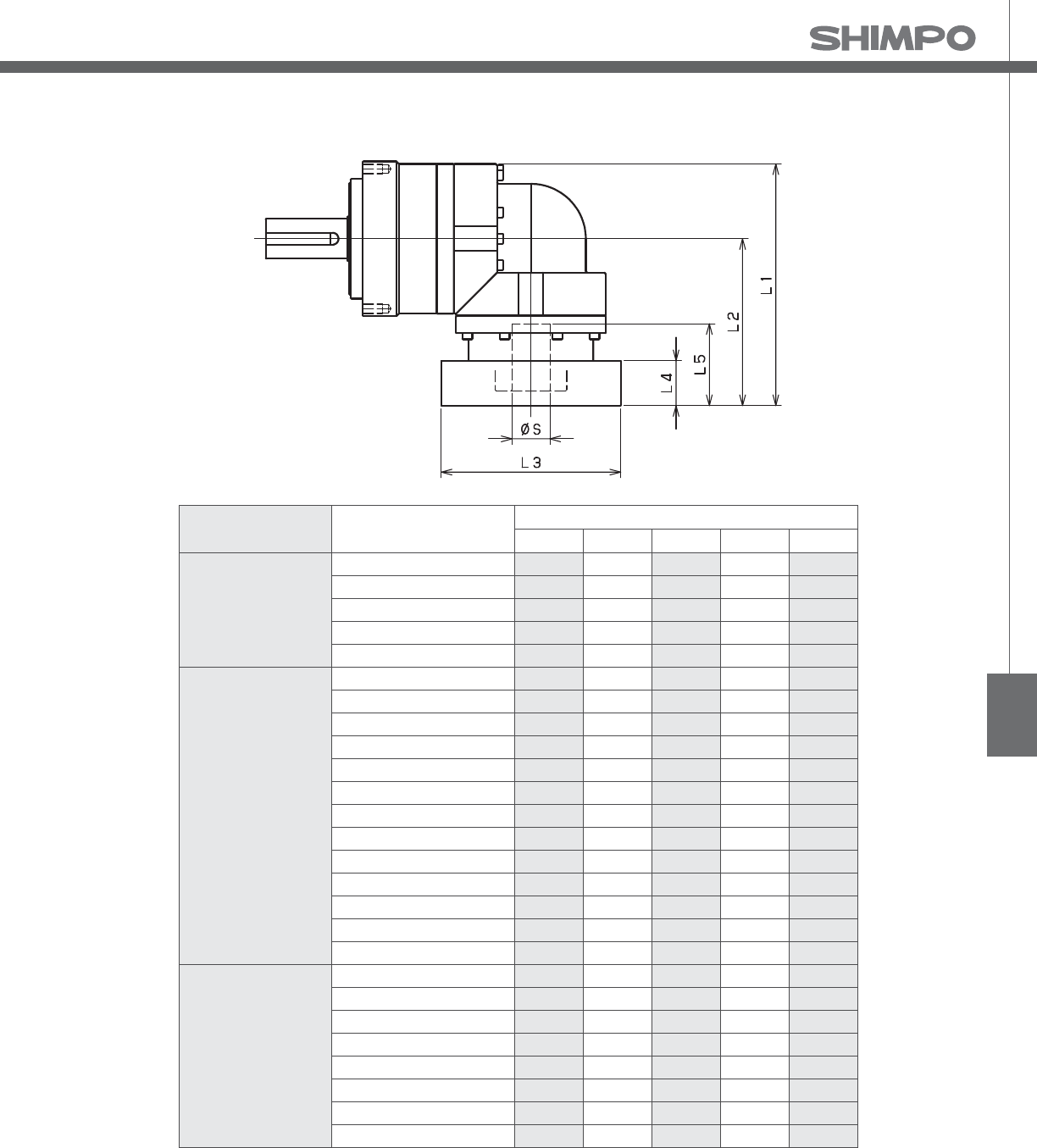
EVL
EVL- 3-Stage Adapter Dimensions
*1) Triple reduction : /~ /
*2) Bushing will be inserted to adapt to motor shaft
Model number **: Adapter code 3-Stage
L1 L2 L3 L4 L5
EVL-070-□-□-8**
(S ≦ 8)
AA•AC•AD•AF•AG•AL•AM•AN•AQ 99.5 64.5 □52 15.5 32
AB•AE•AH•AJ•AK 104.5 69.5 □52 20.5 37
BA•BB•BD•BE•BG•BH•BJ 99.5 64.5 □60 15.5 32
BC•BF 104.5 69.5 □60 20.5 37
CA 104.5 69.5 □70 20.5 37
EVL-070-□-□-14**
(8 S ≦ 14)
BA•BB•BD•BE•BF•BG•BH•BJ•BK•BP 103.5 68.5 □65 16.5 35
BC•BH•BM•BN 108.5 73.5 □65 21.5 40
BL 113.5 78.5 □65 26.5 45
CA•CC 103.5 68.5 □70 16.5 35
CB 108.5 73.5 □70 21.5 40
DA•DB•DC•DD•DF•DH•DJ 103.5 68.5 □80 16.5 35
DE•DL 108.5 73.5 □80 21.5 40
DG•DK 113.5 78.5 □80 26.5 45
EA•EB•EC•EF•EG•EK•EL 103.5 68.5 □90 16.5 35
EJ•EM 108.5 73.5 □90 21.5 40
ED•EE•EH 113.5 78.5 □90 26.5 45
FA 103.5 68.5 □100 16.5 35
FB 113.5 78.5 □100 26.5 45
EVL-070-□-□-19**
(14 S≦19)
DA•DB•DC -- -- -- -- --
DD -- -- -- -- --
DE -- -- -- -- --
EA -- -- -- -- --
EB•ED -- -- -- -- --
EC -- -- -- -- --
FA -- -- -- -- --
FB -- -- -- -- --
A more comprehensive adapter ange o ering can be found using the NIDECSHIMPO Online Selector Tool. The variety is constantly
expanding and being updated on the Selector Tool. If you have any questions or need any support, contact NIDECSHIMPO.
For an explanation on the Adapter Flange Code, please turn to page .

EVL-SERIES Right-angle shaft
EVL- 2-Stage Specifications
EVL- 3-Stage Specifications
Frame Size 090
Stage 2-Stage
Ratio Unit Note 3 4 5 6 7 8 9 10
Nominal Output Torque [Nm] *1 45 60 65 65 65 65 45 45
Maximum Acceleration Torque [Nm] *2 65 90 90 90 90 90 65 65
Emergency Stop Torque [Nm] *3 130 170 220 220 220 220 170 170
Nominal Input Speed [rpm] *4 3000
Maximum Input Speed [rpm] *5 6000
No Load Running Torque [Nm] *6 1.13
Permitted Radial Load [N] *7 810 890 960 1000 1100 1100 1200 1200
Permitted Axial Load [N] *8 930 1100 1200 1300 1300 1400 1500 1600
Maximum Radial Load [N] *9 2400
Maximum Axial Load [N] *10 2200
Moment of Inertia (≤ Ø 8) [kgcm2] -- -- -- -- -- -- -- -- --
Moment of Inertia (≤ Ø 14) [kgcm2] -- 2.120 1.890 1.800 1.760 1.730 1.710 1.700 1.690
Moment of Inertia (≤ Ø 19) [kgcm2] -- 2.450 2.220 2.130 2.090 2.060 2.040 2.030 2.020
Moment of Inertia (≤ Ø 28) [kgcm2] -- 4.570 4.350 4.260 4.210 4.180 4.170 4.160 4.150
E ciency [%] *11 93
Torsional Rigidity [Nm/arc-min] *12 10
Maximum Torsional Backlash [arc-min] -- ≤ 6
Noise Level [dB] *13 80
Protection Class -- *14 IP54 (IP65)
Ambient Temperature [°C] -- 0-40
Permitted Housing Temperature [°C] -- 90
Weight [kg] *15 4.9
Frame Size 090
Stage 3-Stage
Ratio Unit Note 15 16 20 25 28 30 35 40
Nominal Output Torque [Nm] *1 45 65 65 65 65 45 65 65
Maximum Acceleration Torque [Nm] *2 65 110 110 110 110 65 110 110
Emergency Stop Torque [Nm] *3 170 220 220 220 220 170 220 220
Nominal Input Speed [rpm] *4 3000
Maximum Input Speed [rpm] *5 6000
No Load Running Torque [Nm] *6 0.55
Permitted Radial Load [N] *7 1400 1400 1500 1600 1700 1700 1800 1900
Permitted Axial Load [N] *8 1900 1900 2100 2200 2200 2200 2200 2200
Maximum Radial Load [N] *9 2400
Maximum Axial Load [N] *10 2200
Moment of Inertia (≤ Ø 8) [kgcm2] -- 0.340 0.380 0.330 0.320 0.370 0.250 0.320 0.250
Moment of Inertia (≤ Ø 14) [kgcm2] -- 0.410 0.460 0.400 0.400 0.450 0.330 0.400 0.320
Moment of Inertia (≤ Ø 19) [kgcm2] -- 0.600 0.650 0.590 0.590 0.640 0.510 0.590 0.510
Moment of Inertia (≤ Ø 28) [kgcm2] -- -- -- -- -- -- -- -- --
E ciency [%] *11 88
Torsional Rigidity [Nm/arc-min] *12 10
Maximum Torsional Backlash [arc-min] -- ≤ 9
Noise Level [dB] *13 80
Protection Class -- *14 IP54 (IP65)
Ambient Temperature [°C] -- 0-40
Permitted Housing Temperature [°C] -- 90
Weight [kg] *15 4.3

EVL
EVL- 3-Stage Specifications
Frame Size 090
Stage 3-Stage
Ratio Unit Note 45 50 60 70 80 90 100
Nominal Output Torque [Nm] *1 45 65 65 65 65 45 45
Maximum Acceleration Torque [Nm] *2 65 110 1110 110 110 65 65
Emergency Stop Torque [Nm] *3 170 220 220 220 220 170 170
Nominal Input Speed [rpm] *4 3000
Maximum Input Speed [rpm] *5 6000
No Load Running Torque [Nm] *6 0.55
Permitted Radial Load [N] *7 2000 2100 2200 2300 2400 2400 2400
Permitted Axial Load [N] *8 2200 2200 2200 2200 2200 2200 2200
Maximum Radial Load [N] *9 2400
Maximum Axial Load [N] *10 2200
Moment of Inertia (≤ Ø 8) [kgcm2] -- 0.320 0.250 0.250 0.250 0.250 0.250 0.250
Moment of Inertia (≤ Ø 14) [kgcm2] -- 0.390 0.320 0.320 0.320 0.320 0.320 0.320
Moment of Inertia (≤ Ø 19) [kgcm2] -- 0.580 0.510 0.510 0.510 0.510 0.510 0.510
Moment of Inertia (≤ Ø 28) [kgcm2] -- -- -- -- -- -- -- --
E ciency [%] *11 88
Torsional Rigidity [Nm/arc-min] *12 10
Maximum Torsional Backlash [arc-min] -- ≤ 9
Noise Level [dB] *13 80
Protection Class -- *14 IP54 (IP65)
Ambient Temperature [°C] -- 0-40
Permitted Housing Temperature [°C] -- 90
Weight [kg] *15 4.3
*1) At nominal input speed, service life is , hours
*2) The maximum torque when starting or stopping operation
*3) The maximum torque allowed under a stress situation (Permitted , times during service life)
*4) The average input speed
*5) The maximum intermittent input speed
*6) This is the torque at no load applied on the input shaft. The input speed is rpm for EVL
*7) At this load and nominal input speed, service life will be , hours. (The radial load applied to the output side bearing)
*8) At this load and nominal input speed, service life will be , hours. (The axial load applied to the output shaft center)
*9) The maximum radial load that the reducer can accept
*10) The maximum axial load that the reducer can accept
*11) The e ciency at the nominal torque rating
*12) This does not include the lost motion
*13) Contact NIDEC-SHIMPO for the testing conditions and environment
*14) IP (wash-down) is available as an option. Contact NIDECSHIMPO for more details and our food grade options
*15) The weight may vary slightly between models
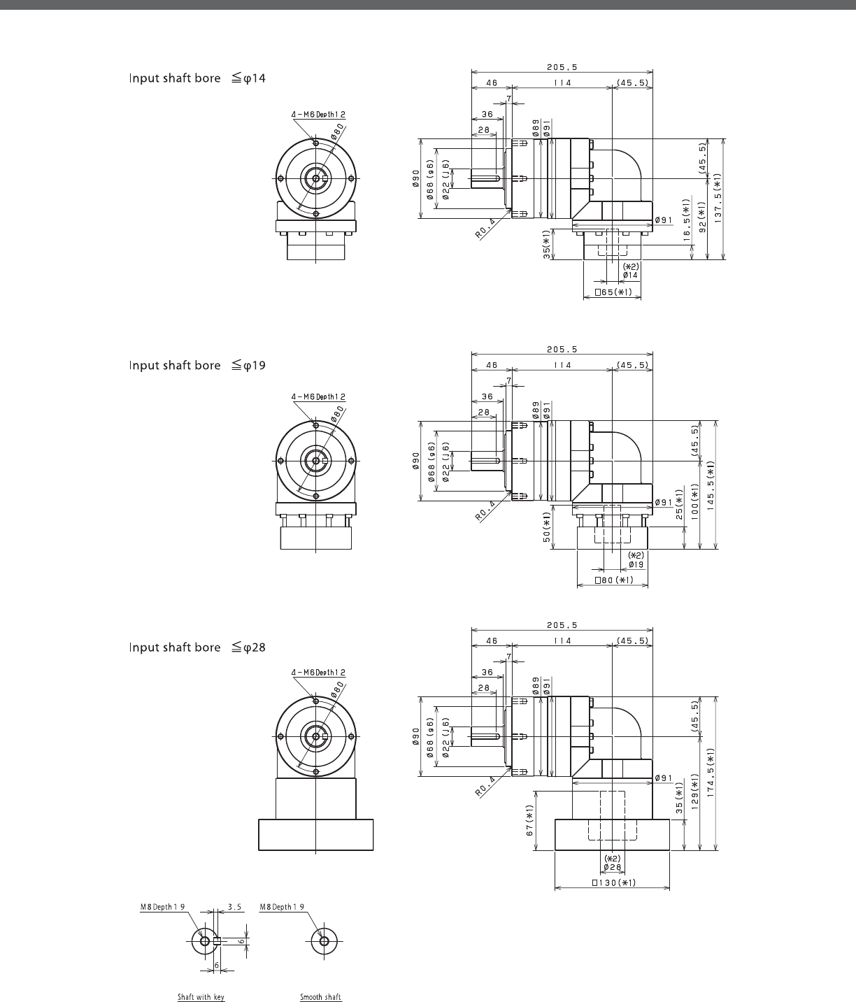
EVL-SERIES Right-angle shaft
EVL- 2-Stage Dimensions
*1) Length will vary depending on motor.
*2) Bushing will be inserted to adapt to motor shaft

EVL
EVL- 3-Stage Dimensions
*1) Length will vary depending on motor.
*2) Bushing will be inserted to adapt to motor shaft

EVL-SERIES Right-angle shaft
EVL- 2-Stage Adapter Dimensions
*1) Double reduction : /~ /
Model number **: Adapter code 2-Stage
L1 L2 L3 L4 L5
EVL-090-□-□-8**
(S≦ 8)
AA•AC•AD•AF•AG•AL•AM•AN•AQ -- -- -- -- --
AB•AE•AH•AJ•AK -- -- -- -- --
BA•BB•BD•BE•BG•BH•BJ -- -- -- -- --
CA -- -- -- -- --
EVL-090-□-□-14**
(8 S≦14)
BA•BB•BD•BE•BF•BG•BH•BJ•BK•BP 137.5 92 □65 16.5 35
BC•BH•BM•BN 142.5 97 □65 21.5 40
CA•CC 137.5 92 □70 16.5 35
DA•DB•DC•DD•DF•DH•DJ 137.5 92 □80 16.5 35
EA•EB•EC•EF•EG•EK•EL 137.5 92 □90 16.5 35
FA 137.5 92 □100 16.5 35
FB 147.5 102 □100 26.5 45
JA 152.5 107 □150 31.5 50
EVL-090-□-□-19**
(14 S≦19)
DA•DB•DC 145.5 100 □80 25 50
EB•ED 145.5 100 □90 25 50
FA 145.5 100 □100 25 50
FB 155.5 110 □100 35 60
GA•GC•GH 150.5 105 □115 30 55
GB•GD•GJ 145.5 100 □115 25 50
GE•GF 155.5 110 □115 35 60
HA 145.5 100 □130 25 50
HB 160.5 115 □130 40 65
HC•HD•HE 150.5 105 □130 30 55
JA 155.5 110 □150 35 60
JB 160.5 115 □150 40 65
EVL-090-□-□-28**
(19 S≦ 28)
FA•FB•FC 174.5 129 □100 35 67
FD•FE 169.5 124 □100 30 62
GA•GB•GC•GD•GE•GF•GG•GH 174.5 129 □115 35 67
HA•HC•HD 174.5 129 □130 35 67
HB 184.5 139 □130 45 77
HE 189.5 144 □130 50 82
HF 169.5 124 □130 30 62
JA•JB•JC•JF 174.5 129 □150 35 67
JD 194.5 149 □150 55 87
JE 184.5 139 □150 45 77
A more comprehensive adapter ange o ering can be found using the NIDECSHIMPO Online Selector Tool. The variety is constantly
expanding and being updated on the Selector Tool. If you have any questions or need any support, contact NIDECSHIMPO.
For an explanation on the Adapter Flange Code, please turn to page .
*) Bushing will be inserted to adapt to motor shaft

EVL
EVL- 3-Stage Adapter Dimensions
*1) Triple reduction : /~ /
Model number **: Adapter code 3-Stage
L1 L2 L3 L4 L5
EVL-090-□-□-8**
(S≦ 8)
AA•AC•AD•AF•AG•AL•AM•AN•AQ 117 71.5 □52 15.5 32
AB•AE•AH•AJ•AK 122 76.5 □52 20.5 37
BA•BB•BD•BE•BG•BH•BJ 117 71.5 □60 15.5 32
CA 122 76.5 □70 20.5 37
EVL-090-□-□-14**
(8 S≦14)
BA•BB•BD•BE•BF•BG•BH•BJ•BK•BP 123 77.5 □65 16.5 35
BC•BH•BM•BN 128 82.5 □65 21.5 40
CA•CC 123 77.5 □70 16.5 35
DA•DB•DC•DD•DF•DH•DJ 123 77.5 □80 16.5 35
EA•EB•EC•EF•EG•EK•EL 123 77.5 □90 16.5 35
FA 123 77.5 □100 16.5 35
FB 133 87.5 □100 26.5 45
JA 138 92.5 □150 31.5 50
EVL-090-□-□-19**
(14 S≦19)
DA•DB•DC 140 94.5 □80 25 50
EB•ED 140 94.5 □90 25 50
FA 140 94.5 □100 25 50
FB 150 104.5 □100 35 60
GA•GC•GH 145 99.5 □115 30 55
GB•GD•GJ 140 94.5 □115 25 50
GE•GF 150 104.5 □115 35 60
HA 140 94.5 □130 25 50
HB 155 109.5 □130 40 65
HC•HD•HE 145 99.5 □130 30 55
JA 150 104.5 □150 35 60
JB 155 109.5 □150 40 65
EVL-090-□-□-28**
(19 S≦ 28)
FA•FB•FC -- -- -- -- --
FD•FE -- -- -- -- --
GA•GB•GC•GD•GE•GF•GG•GH -- -- -- -- --
HA•HC•HD -- -- -- -- --
HB -- -- -- -- --
HE -- -- -- -- --
HF -- -- -- -- --
JA•JB•JC•JF -- -- -- -- --
JD -- -- -- -- --
JE -- -- -- -- --
A more comprehensive adapter ange o ering can be found using the NIDECSHIMPO Online Selector Tool. The variety is constantly
expanding and being updated on the Selector Tool. If you have any questions or need any support, contact NIDECSHIMPO.
For an explanation on the Adapter Flange Code, please turn to page .
*) Bushing will be inserted to adapt to motor shaft

EVL-SERIES Right-angle shaft
EVL- 2-Stage Specifications
EVL- 3-Stage Specifications
Frame Size 120
Stage 2-Stage
Ratio Unit Note 3 4 5 6 7 8 9 10
Nominal Output Torque [Nm] *1 75 100 120 150 150 150 110 110
Maximum Acceleration Torque [Nm] *2 150 200 240 300 300 300 200 200
Emergency Stop Torque [Nm] *3 320 430 500 550 550 550 450 450
Nominal Input Speed [rpm] *4 3000
Maximum Input Speed [rpm] *5 6000
No Load Running Torque [Nm] *6 1.88
Permitted Radial Load [N] *7 1300 1500 1600 1700 1800 1900 1900 2000
Permitted Axial Load [N] *8 1500 1700 1900 2000 2100 2300 2400 2500
Maximum Radial Load [N] *9 4300
Maximum Axial Load [N] *10 3900
Moment of Inertia (≤ Ø 14) [kgcm2] -- -- -- -- -- -- -- -- --
Moment of Inertia (≤ Ø 19) [kgcm2] -- 6.740 5.490 5.020 4.770 4.650 4.550 4.490 4.460
Moment of Inertia (≤ Ø 28) [kgcm2] -- 8.340 7.080 6.610 6.360 6.240 6.140 6.080 6.050
Moment of Inertia (≤ Ø 38) [kgcm2] -- 15.410 14.150 13.690 13.430 13.310 13.220 13.160 13.120
E ciency [%] *11 93
Torsional Rigidity [Nm/arc-min] *12 31
Maximum Torsional Backlash [arc-min] -- ≤ 6
Noise Level [dB] *13 85
Protection Class -- *14 IP54 (IP65)
Ambient Temperature [°C] -- 0-40
Permitted Housing Temperature [°C] -- 90
Weight [kg] *15 10.2
Frame Size 120
Stage 3-Stage
Ratio Unit Note 15 16 20 25 28 30 35 40
Nominal Output Torque [Nm] *1 110 130 150 150 150 110 150 150
Maximum Acceleration Torque [Nm] *2 200 260 300 300 300 200 300 300
Emergency Stop Torque [Nm] *3 450 550 550 550 550 450 550 550
Nominal Input Speed [rpm] *4 3000
Maximum Input Speed [rpm] *5 6000
No Load Running Torque [Nm] *6 1.11
Permitted Radial Load [N] *7 2300 2300 2500 2700 2800 2900 3000 3200
Permitted Axial Load [N] *8 3000 3100 3400 3700 3900 3900 3900 3900
Maximum Radial Load [N] *9 4300
Maximum Axial Load [N] *10 3900
Moment of Inertia (≤ Ø 14) [kgcm2] -- 2.250 2.460 2.200 2.180 2.400 1.870 2.160 1.860
Moment of Inertia (≤ Ø 19) [kgcm2] -- 2.580 2.790 2.530 2.510 2.730 2.200 2.490 2.190
Moment of Inertia (≤ Ø 28) [kgcm2] -- 4.700 4.910 4.650 4.640 4.860 4.330 4.620 4.320
Moment of Inertia (≤ Ø 38) [kgcm2] -- -- -- -- -- -- -- -- --
E ciency [%] *11 88
Torsional Rigidity [Nm/arc-min] *12 31
Maximum Torsional Backlash [arc-min] -- ≤ 9
Noise Level [dB] *13 85
Protection Class -- *14 IP54 (IP65)
Ambient Temperature [°C] -- 0-40
Permitted Housing Temperature [°C] -- 90
Weight [kg] *15 10

EVL
EVL- 3-Stage Specifications
Frame Size 120
Stage 3-Stage
Ratio Unit Note 45 50 60 70 80 90 100
Nominal Output Torque [Nm] *1 110 150 150 150 150 110 110
Maximum Acceleration Torque [Nm] *2 200 300 300 300 300 200 200
Emergency Stop Torque [Nm] *3 450 550 550 550 550 450 450
Nominal Input Speed [rpm] *4 3000
Maximum Input Speed [rpm] *5 6000
No Load Running Torque [Nm] *6 1.11
Permitted Radial Load [N] *7 3300 3400 3600 3800 4000 4200 4300
Permitted Axial Load [N] *8 3900 3900 3900 3900 3900 3900 3900
Maximum Radial Load [N] *9 4300
Maximum Axial Load [N] *10 3900
Moment of Inertia (≤ Ø 14) [kgcm2] -- 2.150 1.860 1.850 1.850 1.850 1.850 1.850
Moment of Inertia (≤ Ø 19) [kgcm2] -- 2.480 2.190 2.180 2.180 2.180 2.180 2.180
Moment of Inertia (≤ Ø 28) [kgcm2] -- 4.610 4.310 4.310 4.310 4.310 4.310 4.310
Moment of Inertia (≤ Ø 38) [kgcm2] -- -- -- -- -- -- -- --
E ciency [%] *11 88
Torsional Rigidity [Nm/arc-min] *12 31
Maximum Torsional Backlash [arc-min] -- ≤ 9
Noise Level [dB] *13 85
Protection Class -- *14 IP54 (IP65)
Ambient Temperature [°C] -- 0-40
Permitted Housing Temperature [°C] -- 90
Weight [kg] *15 10
*1) At nominal input speed, service life is , hours
*2) The maximum torque when starting or stopping operation
*3) The maximum torque allowed under a stress situation (Permitted , times during service life)
*4) The average input speed
*5) The maximum intermittent input speed
*6) This is the torque at no load applied on the input shaft. The input speed is rpm for EVL
*7) At this load and nominal input speed, service life will be , hours. (The radial load applied to the output side bearing)
*8) At this load and nominal input speed, service life will be , hours. (The axial load applied to the output shaft center)
*9) The maximum radial load that the reducer can accept
*10) The maximum axial load that the reducer can accept
*11) The e ciency at the nominal torque rating
*12) This does not include the lost motion
*13) Contact NIDEC-SHIMPO for the testing conditions and environment
*14) IP (wash-down) is available as an option. Contact NIDECSHIMPO for more details and our food grade options
*15) The weight may vary slightly between models

EVL-SERIES Right-angle shaft
EVL- 2-Stage Dimensions
*1) Length will vary depending on motor
*2) Bushing will be inserted to adapt to motor shaft

EVL
EVL- 3-Stage Dimensions
*1) Length will vary depending on motor
*2) Bushing will be inserted to adapt to motor shaft

EVL-SERIES Right-angle shaft
EVL- 2-Stage Adapter Dimensions
*1) Double reduction : /~ /
Model number **: Adapter code 2-Stage
L1 L2 L3 L4 L5
EVL-120-□-□-14**
(S≦ 14)
BA•BB•BD•BE•BF•BG•BH•BJ•BK•BP -- -- -- -- --
BC•BH•BM•BN -- -- -- -- --
CA•CC ----------
DA•DB•DC•DD•DF•DH•DJ -- -- -- -- --
EA•EB•EC•EF•EG•EK•EL -- -- -- -- --
FA -- -- -- -- --
FB -- -- -- -- --
JA -- -- -- -- --
EVL-120-□-□-19**
(14 S≦ 19)
DA•DB•DC 170 110 □80 25 50
EB•ED 170 110 □90 25 50
FA 170 110 □100 25 50
FB 180 120 □100 35 60
GB•GD•GJ 170 110 □115 25 50
HA 170 110 □130 25 50
HB 185 125 □130 40 65
JA 180 120 □150 35 60
EVL-120-□-□-28**
(19 S≦ 28)
FA•FB•FC 196 136 □100 35 67
FD•FE 191 131 □100 30 62
GA•GB•GC•GD•GE•GF•GG•GH 196 136 □115 35 67
HA•HC•HD 196 136 □130 35 67
HB 206 146 □130 45 77
HE 211 151 □130 50 82
HF 191 131 □130 30 62
JA•JB•JC•JF 196 136 □150 35 67
JD 216 156 □150 55 87
JE 206 146 □150 45 77
KA•KB•KE 196 136 □180 35 67
KD 206 146 □180 45 77
EVL-120-□-□-38**
(28 S≦ 38)
HA 213 153 □130 45 82
HB•HE 208 148 □130 40 77
JA 213 153 □150 45 82
KA•KB•KC 213 153 □180 45 82
KD 248 188 □180 80 117
KE 228 168 □180 60 97
A more comprehensive adapter ange o ering can be found using the NIDECSHIMPO Online Selector Tool. The variety is constantly
expanding and being updated on the Selector Tool. If you have any questions or need any support, contact NIDECSHIMPO.
For an explanation on the Adapter Flange Code, please turn to page .
*) Bushing will be inserted to adapt to motor shaft

EVL
EVL- 3-Stage Adapter Dimensions
*1) Triple reduction : /~ /
Model number **: Adapter code 3-Stage
L1 L2 L3 L4 L5
EVL-120-□-□-14**
(S≦ 14)
BA•BB•BD•BE•BF•BG•BH•BJ•BK•BP 152 92 □65 16.5 35
BC•BH•BM•BN 157 97 □65 21.5 40
CA•CC 152 92 □70 16.5 35
DA•DB•DC•DD•DF•DH•DJ 152 92 □80 16.5 35
EA•EB•EC•EF•EG•EK•EL 152 92 □90 16.5 35
FA 152 92 □100 16.5 35
FB 162 102 □100 26.5 45
JA 167 107 □150 31.5 50
EVL-120-□-□-19**
(14 S≦ 19)
DA•DB•DC 160 100 □80 25 50
EB•ED 160 100 □90 25 50
FA 160 100 □100 25 50
FB 170 110 □100 35 60
GB•GD•GJ 160 100 □115 25 50
HA 160 100 □130 25 50
HB 175 115 □130 40 65
JA 170 110 □150 35 60
EVL-120-□-□-28**
(19 S≦ 28)
FA•FB•FC 189 129 □100 35 67
FD•FE 184 124 □100 30 62
GA•GB•GC•GD•GE•GF•GG•GH 189 129 □115 35 67
HA•HC•HD 189 129 □130 35 67
HB 199 139 □130 45 77
HE 204 144 □130 50 82
HF 184 124 □130 30 62
JA•JB•JC•JF 189 129 □150 35 67
JD 209 149 □150 55 87
JE 199 139 □150 45 77
KA•KB•KE 189 129 □180 35 67
KD 199 139 □180 45 77
EVL-120-□-□-38**
(28 S≦ 38)
HA -- -- -- -- --
HB•HE -- -- -- -- --
JA -- -- -- -- --
KA•KB•KC -- -- -- -- --
KD -- -- -- -- --
KE -- -- -- -- --
A more comprehensive adapter ange o ering can be found using the NIDECSHIMPO Online Selector Tool. The variety is constantly
expanding and being updated on the Selector Tool. If you have any questions or need any support, contact NIDECSHIMPO.
For an explanation on the Adapter Flange Code, please turn to page .
*) Bushing will be inserted to adapt to motor shaft

EVL-SERIES Right-angle shaft
EVL- 2-Stage Specifications
EVL- 3-Stage Specifications
Frame Size 155
Stage 2-Stage
Ratio Unit Note 3 4 5 6 7 8 9 10
Nominal Output Torque [Nm] *1 130 170 200 260 300 300 200 200
Maximum Acceleration Torque [Nm] *2 260 340 400 520 600 600 400 400
Emergency Stop Torque [Nm] *3 700 950 1100 1100 1100 1100 750 750
Nominal Input Speed [rpm] *4 2000
Maximum Input Speed [rpm] *5 4000
No Load Running Torque [Nm] *6 3.26
Permitted Radial Load [N] *7 3200 3500 3800 4000 4200 4400 4600 4700
Permitted Axial Load [N] *8 2400 2700 3000 3300 3500 3700 3900 4100
Maximum Radial Load [N] *9 9100
Maximum Axial Load [N] *10 8200
Moment of Inertia (≤ Ø 19) [kgcm2] -- -- -- -- -- -- -- -- --
Moment of Inertia (≤ Ø 28) [kgcm2] -- 23.130 18.570 16.910 16.010 15.580 15.230 14.770 14.660
Moment of Inertia (≤ Ø 38) [kgcm2] -- 27.500 22.940 21.280 20.380 19.950 19.610 19.410 19.030
Moment of Inertia (≤ Ø 48) [kgcm2] -- 40.730 36.170 34.510 33.610 33.180 32.840 32.370 32.260
E ciency [%] *11 93
Torsional Rigidity [Nm/arc-min] *12 60
Maximum Torsional Backlash [arc-min] -- ≤ 6
Noise Level [dB] *13 85
Protection Class -- *14 IP54 (IP65)
Ambient Temperature [°C] -- 0-40
Permitted Housing Temperature [°C] -- 90
Weight [kg] *15 19.8
Frame Size 155
Stage 3-Stage
Ratio Unit Note 15 16 20 25 28 30 35 40
Nominal Output Torque [Nm] *1 200 300 300 300 300 200 300 300
Maximum Acceleration Torque [Nm] *2 400 600 600 600 600 400 600 600
Emergency Stop Torque [Nm] *3 750 1100 1100 1100 1100 750 1100 1100
Nominal Input Speed [rpm] *4 2000
Maximum Input Speed [rpm] *5 4000
No Load Running Torque [Nm] *6 2.56
Permitted Radial Load [N] *7 5400 5500 6000 6400 6700 6800 7200 7500
Permitted Axial Load [N] *8 4900 5000 5500 6100 6400 6600 7000 7500
Maximum Radial Load [N] *9 9100
Maximum Axial Load [N] *10 8200
Moment of Inertia (≤ Ø 19) [kgcm2] -- 6.400 7.290 6.220 6.150 7.090 4.990 6.090 4.950
Moment of Inertia (≤ Ø 28) [kgcm2] -- 8.000 8.880 7.810 7.750 8.680 6.580 7.690 6.540
Moment of Inertia (≤ Ø 38) [kgcm2] -- 15.070 15.960 14.890 14.820 15.760 13.660 14.760 13.610
Moment of Inertia (≤ Ø 48) [kgcm2] -- -- -- -- -- -- -- -- --
E ciency [%] *11 88
Torsional Rigidity [Nm/arc-min] *12 60
Maximum Torsional Backlash [arc-min] -- ≤ 9
Noise Level [dB] *13 85
Protection Class -- *14 IP54 (IP65)
Ambient Temperature [°C] -- 0-40
Permitted Housing Temperature [°C] -- 90
Weight [kg] *15 20.4

EVL
EVL- 3-Stage Specifications
Frame Size 155
Stage 3-Stage
Ratio Unit Note 45 50 60 70 80 90 100
Nominal Output Torque [Nm] *1 200 300 300 300 300 200 200
Maximum Acceleration Torque [Nm] *2 400 600 600 600 600 400 400
Emergency Stop Torque [Nm] *3 750 1100 1100 1100 1100 750 750
Nominal Input Speed [rpm] *4 2000
Maximum Input Speed [rpm] *5 4000
No Load Running Torque [Nm] *6 2.56
Permitted Radial Load [N] *7 7800 8100 8600 9100 9100 9100 9100
Permitted Axial Load [N] *8 7900 8200 8200 8200 8200 8200 8200
Maximum Radial Load [N] *9 9100
Maximum Axial Load [N] *10 8200
Moment of Inertia (≤ Ø 19) [kgcm2] -- 6.070 4.930 4.920 4.910 4.910 4.910 4.910
Moment of Inertia (≤ Ø 28) [kgcm2] -- 7.660 6.520 6.510 6.510 6.500 6.500 6.500
Moment of Inertia (≤ Ø 38) [kgcm2] -- 14.740 13.590 13.590 13.580 13.580 13.570 13.570
Moment of Inertia (≤ Ø 48) [kgcm2] -- -- -- -- -- -- -- --
E ciency [%] *11 88
Torsional Rigidity [Nm/arc-min] *12 60
Maximum Torsional Backlash [arc-min] -- ≤ 9
Noise Level [dB] *13 85
Protection Class -- *14 IP54 (IP65)
Ambient Temperature [°C] -- 0-40
Permitted Housing Temperature [°C] -- 90
Weight [kg] *15 20.4
*1) At nominal input speed, service life is , hours
*2) The maximum torque when starting or stopping operation
*3) The maximum torque allowed under a stress situation (Permitted , times during service life)
*4) The average input speed
*5) The maximum intermittent input speed
*6) This is the torque at no load applied on the input shaft. The input speed is rpm for EVL
*7) At this load and nominal input speed, service life will be , hours. (The radial load applied to the output side bearing)
*8) At this load and nominal input speed, service life will be , hours. (The axial load applied to the output shaft center)
*9) The maximum radial load that the reducer can accept
*10) The maximum axial load that the reducer can accept
*11) The e ciency at the nominal torque rating
*12) This does not include the lost motion
*13) Contact NIDEC-SHIMPO for the testing conditions and environment
*14) IP (wash-down) is available as an option. Contact NIDECSHIMPO for more details and our food grade options
*15) The weight may vary slightly between models
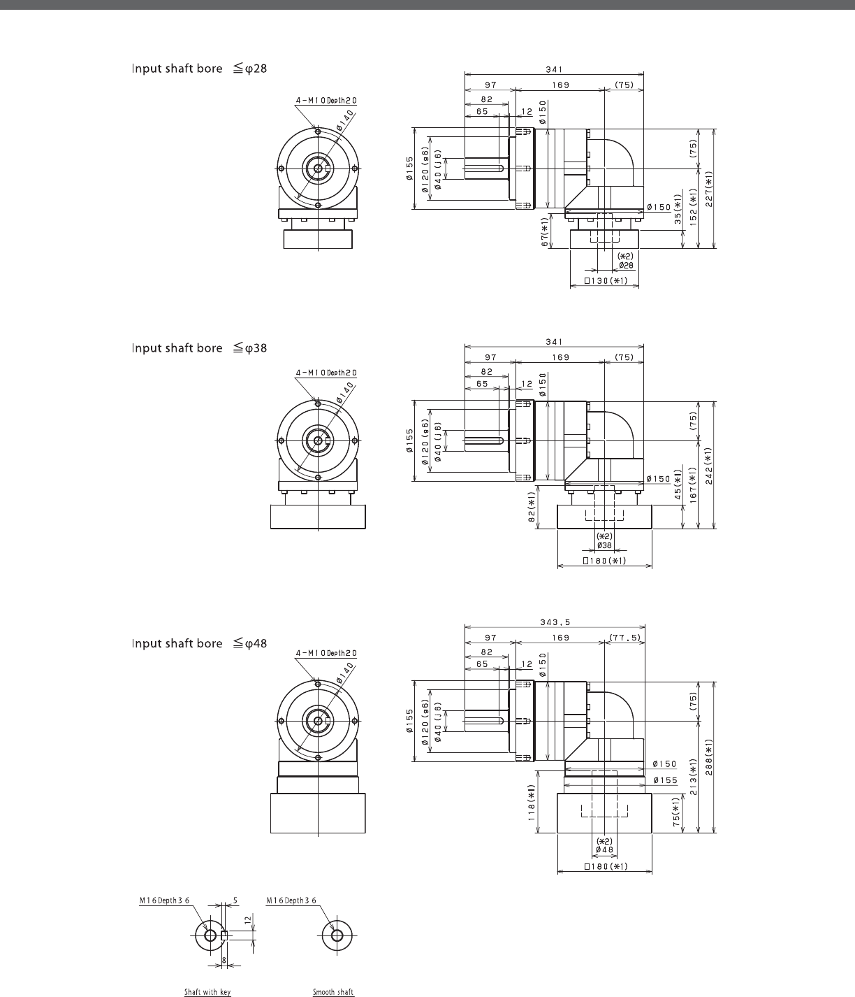
EVL-SERIES Right-angle shaft
EVL- 2-Stage Dimensions
*1) Length will vary depending on motor.
*2) Bushing will be inserted to adapt to motor shaft

EVL
EVL- 3-Stage Dimensions
*1) Length will vary depending on motor.
*2) Bushing will be inserted to adapt to motor shaft

EVL-SERIES Right-angle shaft
EVL- 2-Stage Adapter Dimensions
*1) Double reduction : /~ /
Model number **: Adapter code 2-Stage
L1 L2 L3 L4 L5
EVL-155-□-□-19**
(S≦19)
DA•DB•DC -- -- -- -- --
EB•ED -- -- -- -- --
FA -- -- -- -- --
FB -- -- -- -- --
GB•GD•GJ -- -- -- -- --
HA -- -- -- -- --
HB -- -- -- -- --
JA -- -- -- -- --
EVL-155-□-□-28**
(19 S≦ 28)
FA•FB•FC 229.5 152 □100 35 67
GA•GB•GC•GD•GE•GF•GG•GH 229.5 152 □115 35 67
HA•HC•HD 229.5 152 □130 35 67
HB 239.5 162 □130 45 77
HF 224.5 147 □130 30 62
JA•JB•JC•JF 229.5 152 □150 35 67
KA•KB•KE 229.5 152 □180 35 67
LA 229.5 152 □200 35 67
LB 239.5 162 □200 45 77
MA 229.5 152 □220 35 67
MB 239.5 162 □220 45 77
EVL-155-□-□-38**
(28 S≦ 38)
HA 244.5 167 □130 45 82
HB•HE 239.5 162 □130 40 77
JA 244.5 167 □150 45 82
KA•KB•KC 244.5 167 □180 45 82
KD 279.5 202 □180 80 117
KE 259.5 182 □180 60 97
LB 254.5 177 □200 55 92
MA•MB 244.5 167 □220 45 82
MC 259.5 182 □220 60 97
MD 254.5 177 □220 55 92
EVL-155-□-□-48**
(38 S≦ 48)
KA 290.5 213 □180 75 118
KB•KC 270.5 193 □180 55 98
LA 270.5 193 □200 55 98
MA 270.5 193 □220 55 98
MB 290.5 213 □220 75 118
A more comprehensive adapter ange o ering can be found using the NIDECSHIMPO Online Selector Tool. The variety is constantly
expanding and being updated on the Selector Tool. If you have any questions or need any support, contact NIDECSHIMPO.
For an explanation on the Adapter Flange Code, please turn to page .
*) Bushing will be inserted to adapt to motor shaft

EVL
EVL- 3-Stage Adapter Dimensions
*1) Triple reduction : /~ /
Model number **: Adapter code 3-Stage
L1 L2 L3 L4 L5
EVL-155-□-□-19**
(S≦19)
DA•DB•DC 187.5 110 □80 25 50
EB•ED 187.5 110 □90 25 50
FA 187.5 110 □100 25 50
FB 197.5 120 □100 35 60
GB•GD•GJ 187.5 110 □115 25 50
HA 187.5 110 □130 25 50
HB 202.5 125 □130 40 65
JA 197.5 120 □150 35 60
EVL-155-□-□-28**
(19 S≦ 28)
FA•FB•FC 213.5 136 □100 35 67
GA•GB•GC•GD•GE•GF•GG•GH 213.5 136 □115 35 67
HA•HC•HD 213.5 136 □130 35 67
HB 223.5 146 □130 45 77
HF 208.5 131 □130 30 62
JA•JB•JC•JF 213.5 136 □150 35 67
KA•KB•KE 213.5 136 □180 35 67
LA 213.5 136 □200 35 67
LB 223.5 146 □200 45 77
MA 213.5 136 □220 35 67
MB 223.5 146 □220 45 77
EVL-155-□-□-38**
(28 S≦ 38)
HA 230.5 153 □130 45 82
HB•HE 225.5 148 □130 40 77
JA 230.5 153 □150 45 82
KA•KB•KC 230.5 153 □180 45 82
KD 265.5 188 □180 80 117
KE 245.5 168 □180 60 97
LB 240.5 163 □200 55 92
MA•MB 230.5 153 □220 45 82
MC 245.5 168 □220 60 97
MD 240.5 163 □220 55 92
EVL-155-□-□-48**
(38 S≦ 48)
KA -- -- -- -- --
KB•KC -- -- -- -- --
LA -- -- -- -- --
MA -- -- -- -- --
MB -- -- -- -- --
A more comprehensive adapter ange o ering can be found using the NIDECSHIMPO Online Selector Tool. The variety is constantly
expanding and being updated on the Selector Tool. If you have any questions or need any support, contact NIDECSHIMPO.
For an explanation on the Adapter Flange Code, please turn to page .
*) Bushing will be inserted to adapt to motor shaft

EVL-SERIES Right-angle shaft
EVL- 2-Stage Specifications
Frame Size 205
Stage 2-Stage
Ratio Units Note 3 4 5 6 7 8 9 10
Nominal Output Torque [Nm] *1 400 575 600 600 600 600 400 400
Maximum Acceleration Torque [Nm] *2 575 770 960 1120 1120 1120 775 775
Emergency Stop Torque [Nm] *3 1300 1700 2000 2500 2500 2500 2000 2000
Nominal Input Speed [rpm] *4 1500
Maximum Input Speed [rpm] *5 3000
No Load Running Torque [Nm] *6 10.8
Permitted Radial Load [N] *7 5600 6200 6700 7100 7400 7800 8100 8400
Permitted Axial Load [N] *8 4300 4900 5400 5800 6300 6600 7000 7300
Maximum Radial Load [N] *9 15000
Maximum Axial Load [N] *10 14000
Moment of Inertia (≤Ø 28) [kgcm2] -- -- -- -- -- -- -- -- --
Moment of Inertia (≤Ø 38) [kgcm2] -- 93.71 77.72 71.89 68.74 66.43 65.27 64.60 64.28
Moment of Inertia (≤Ø 48) [kgcm2] -- 128.6 112.6 106.8 103.6 101.3 100.1 99.46 99.14
Moment of Inertia (≤ Ø 65) [kgcm2] -- 214.2 198.2 192.4 189.2 186.9 185.7 185.1 184.7
E ciency [%] *11 93
Torsional Rigidity [Nm/arcmin] *12 175
Maximum Torsional Backlash [Arc-min] -- ≤ 8
Noise Level [dB] *13 ≤ 85
Protection Class -- *14 IP54 (IP65)
Ambient Temperature [°C] -- 0-40
Permitted Housing Temperature [°C] -- 90
Weight [kg] *15 52
Frame Size 205
Stage 3-Stage
Ratio Units Note 15 16 20 25 28 30 35 40
Nominal Output Torque [Nm] *1 400 555 600 600 600 400 600 600
Maximum Acceleration Torque [Nm] *2 775 1120 1120 1120 1120 775 1120 1120
Emergency Stop Torque [Nm] *3 2000 2500 2500 2500 2500 2000 2500 2500
Nominal Input Speed [rpm] *4 1500
Maximum Input Speed [rpm] *5 3000
No Load Running Torque [Nm] *6 4.7
Permitted Radial Load [N] *7 9600 9800 11000 11000 12000 12000 13000 13000
Permitted Axial Load [N] *8 8700 8900 9900 11000 11000 12000 13000 13000
Maximum Radial Load [N] *9 15000
Maximum Axial Load [N] *10 14000
Moment of Inertia (≤Ø 28) [kgcm2] -- 11.49 12.09 11.15 10.98 11.59 10.33 10.83 10.24
Moment of Inertia (≤Ø 38) [kgcm2] -- 20.28 20.88 19.94 19.77 20.38 19.11 19.62 19.03
Moment of Inertia (≤Ø 48) [kgcm2] -- 25.10 25.70 24.76 24.59 25.20 23.94 24.44 23.85
Moment of Inertia (≤ Ø 65) [kgcm2] -- -- -- -- -- -- -- -- --
E ciency [%] *11 88
Torsional Rigidity [Nm/arcmin] *12 175
Maximum Torsional Backlash [Arc-min] -- ≤ 11
Noise Level [dB] *13 ≤ 85
Protection Class -- *14 IP54 (IP65)
Ambient Temperature [°C] -- 0-40
Permitted Housing Temperature [°C] -- 90
Weight [kg] *15 39
EVL- 3-Stage Specifications

EVL
EVL- 3-Stage Specifications
Frame Size 205
Stage 3-Stage
Ratio Units Note 45 50 60 70 80 90 100
Nominal Output Torque [Nm] *1 400 600 600 600 600 400 400
Maximum Acceleration Torque [Nm] *2 775 1120 1120 1120 1120 775 775
Emergency Stop Torque [Nm] *3 2000 2500 2500 2500 2500 2000 2000
Nominal Input Speed [rpm] *4 1500
Maximum Input Speed [rpm] *5 3000
No Load Running Torque [Nm] *6 4.7
Permitted Radial Load [N] *7 14000 14000 15000 15000 15000 15000 15000
Permitted Axial Load [N] *8 14000 14000 14000 14000 14000 14000 14000
Maximum Radial Load [N] *9 15000
Maximum Axial Load [N] *10 14000
Moment of Inertia (≤Ø 28) [kgcm2] -- 10.76 10.20 10.18 10.16 10.15 10.15 10.14
Moment of Inertia (≤Ø 38) [kgcm2] -- 19.55 18.99 18.96 18.95 18.94 18.93 18.93
Moment of Inertia (≤Ø 48) [kgcm2] -- 24.37 23.81 23.78 23.77 23.76 23.75 23.75
Moment of Inertia (≤ Ø 65) [kgcm2] -- -- -- -- -- -- -- --
E ciency [%] *11 88
Torsional Rigidity [Nm/arcmin] *12 175
Maximum Torsional Backlash [Arc-min] -- ≤ 11
Noise Level [dB] *13 ≤ 85
Protection Class -- *14 IP54 (IP65)
Ambient Temperature [°C] -- 0-40
Permitted Housing Temperature [°C] -- 90
Weight [kg] *15 39
*1) At nominal input speed, service life is , hours
*2) The maximum torque when starting or stopping operation
*3) The maximum torque allowed under a stress situation (Permitted , times during service life)
*4) The average input speed
*5) The maximum intermittent input speed
*6) This is the torque at no load applied on the input shaft. The input speed is rpm for EVL
*7) At this load and nominal input speed, service life will be , hours. (The radial load applied to the output side bearing)
*8) At this load and nominal input speed, service life will be , hours. (The axial load applied to the output shaft center)
*9) The maximum radial load that the reducer can accept
*10) The maximum axial load that the reducer can accept
*11) The e ciency at the nominal torque rating
*12) This does not include the lost motion
*13) Contact NIDEC-SHIMPO for the testing conditions and environment
*14) IP (wash-down) is available as an option. Contact NIDECSHIMPO for more details and our food grade options
*15) The weight may vary slightly between models

EVL-SERIES Right-angle shaft
EVL- 2-Stage Dimensions
*1) Length will vary depending on motor.
*2) Bushing will be inserted to adapt to motor shaft

EVL
EVL- 3-Stage Dimensions
*1) Length will vary depending on motor.
*2) Bushing will be inserted to adapt to motor shaft

EVL-SERIES Right-angle shaft
EVL- 2-Stage Adapter Dimensions
Model number **: Adapter code 2-Stage
L1 L2 L3 L4 L5
EVL-205-□-□-28**
(S≦ 28)
FA•FB•FC -- -- -- -- --
GA•GB•GC•GD•GE•GF•GG•GH -- -- -- -- --
HA•HC•HD -- -- -- -- --
HB -- -- -- -- --
HF -- -- -- -- --
JA•JB•JC•JF -- -- -- -- --
KA•KB•KE -- -- -- -- --
LA -- -- -- -- --
LB -- -- -- -- --
MA -- -- -- -- --
MB -- -- -- -- --
EVL-205-□-□-38**
(28 S≦ 38)
HA 331.5 231.5 □130 45 82
HB•HE 326.5 226.5 □130 40 77
JA 331.5 231.5 □150 45 82
KA•KB•KC 331.5 231.5 □180 45 82
KD 366.5 266.5 □180 80 117
KE 346.5 246.5 □180 60 97
LA 331.5 231.5 □200 45 82
LB 341.5 241.5 □200 55 92
MA•MB 331.5 231.5 □220 45 82
MC 346.5 246.5 □220 60 97
MD 341.5 241.5 □220 55 92
NA 331.5 231.5 □250 45 82
EVL-205-□-□-48**
(38 S≦ 48)
KA 368 268 □180 75 118
KB•KC 348 248 □180 55 98
LA 348 248 □200 55 98
MA 348 248 □220 55 98
MB 368 268 □220 75 118
NA 368 268 □250 75 118
PA 368 268 □280 75 118
EVL-205-□-□-65**
(48 S≦ 65)
MA•MB•MC•MD 381 281 □220 80 122
NA•NC 381 281 □250 80 122
NB•ND 411 311 □250 110 152
PA 401 301 □280 100 142
PB 411 311 □280 110 152
*1) Double reduction : /~ /
A more comprehensive adapter ange o ering can be found using the NIDECSHIMPO Online Selector Tool. The variety is constantly
expanding and being updated on the Selector Tool. If you have any questions or need any support, contact NIDECSHIMPO.
For an explanation on the Adapter Flange Code, please turn to page .
*) Bushing will be inserted to adapt to motor shaft

EVL
EVL- 3-Stage Adapter Dimensions
Model number **: Adapter code 3-Stage
L1 L2 L3 L4 L5
EVL-205-□-□-28**
(S≦ 28)
FA•FB•FC 252 152 □100 35 67
GA•GB•GC•GD•GE•GF•GG•GH 252 152 □115 35 67
HA•HC•HD 252 152 □130 35 67
HB 262 162 □130 45 77
HF 247 147 □130 30 62
JA•JB•JC•JF 252 152 □150 35 67
KA•KB•KE 252 152 □180 35 67
LA 252 152 □200 35 67
LB 262 162 □200 45 77
MA 252 152 □220 35 67
MB 262 162 □220 45 77
EVL-205-□-□-38**
(28 S≦ 38)
HA 267 167 □130 45 82
HB•HE 262 162 □130 40 77
JA 267 167 □150 45 82
KA•KB•KC 267 167 □180 45 82
KD 302 202 □180 80 117
KE 282 182 □180 60 97
LA 267 167 □200 45 82
LB 277 177 □200 55 92
MA•MB 267 167 □220 45 82
MC 282 182 □220 60 97
MD 277 177 □220 55 92
NA 267 167 □250 45 82
EVL-205-□-□-48**
(38 S≦ 48)
KA 313 213 □180 75 118
KB•KC 293 193 □180 55 98
LA 293 193 □200 55 98
MA 293 193 □220 55 98
MB 313 213 □220 75 118
NA 313 213 □250 75 118
PA 313 213 □280 75 118
EVL-205-□-□-65**
(48 S≦ 65)
MA•MB•MC•MD -- -- -- -- --
NA•NC -- -- -- -- --
NB•ND -- -- -- -- --
PA -- -- -- -- --
PB -- -- -- -- --
*1) Triple reduction : /~ /
A more comprehensive adapter ange o ering can be found using the NIDECSHIMPO Online Selector Tool. The variety is constantly
expanding and being updated on the Selector Tool. If you have any questions or need any support, contact NIDECSHIMPO.
For an explanation on the Adapter Flange Code, please turn to page .
*) Bushing will be inserted to adapt to motor shaft

EVL-SERIES Right-angle shaft
EVL- 2-Stage Specifications
EVL- 3-Stage Specifications
Frame Size 235
Stage 2-Stage
Ratio Units Note 3 4 5 6 7 8 9 10
Nominal Output Torque [Nm] *1 575 765 960 1150 1200 1200 800 800
Maximum Acceleration Torque [Nm] *2 1015 1355 1695 1840 1840 1760 1520 1280
Emergency Stop Torque [Nm] *3 2500 3300 4000 4500 4500 4500 3600 3600
Nominal Input Speed [rpm] *4 1000
Maximum Input Speed [rpm] *5 2000
No Load Running Torque [Nm] *6 14.5
Permitted Radial Load [N] *7 5800 6400 6900 7300 7700 8000 8400 8700
Permitted Axial Load [N] *8 6400 7200 7900 8600 9200 9700 10000 11000
Maximum Radial Load [N] *9 15000
Maximum Axial Load [N] *10 14000
Moment of Inertia (≤Ø 38) [kgcm2] -- -- -- -- -- -- -- -- --
Moment of Inertia (≤Ø 48) [kgcm2] -- 148.00 122.90 113.30 108.10 104.70 102.70 101.60 101.00
Moment of Inertia (≤ Ø 65) [kgcm2] -- 223.20 198.10 188.60 183.30 180.00 178.00 176.80 176.20
E ciency [%] *11 93
Torsional Rigidity [Nm/arcmin] *12 400
Maximum Torsional Backlash [Arc-min] -- ≤ 8
Noise Level [dB] *13 ≤ 85
Protection Class -- *14 IP54 (IP65)
Ambient Temperature [°C] -- 0-40
Permitted Housing Temperature [°C] -- 90
Weight [kg] *15 68
Frame Size 235
Stage 3-Stage
Ratio Units Note 15 16 20 25 28 30 35 40
Nominal Output Torque [Nm] *1 800 1200 1200 1200 1200 800 1200 1200
Maximum Acceleration Torque [Nm] *2 1280 1840 1840 1840 1840 1280 1840 1840
Emergency Stop Torque [Nm] *3 3600 4500 4500 4500 4500 3600 4500 4500
Nominal Input Speed [rpm] *4 1000
Maximum Input Speed [rpm] *5 2000
No Load Running Torque [Nm] *6 10.2
Permitted Radial Load [N] *7 9900 10000 11000 12000 12000 13000 13000 14000
Permitted Axial Load [N] *8 13000 13000 14000 14000 14000 14000 14000 14000
Maximum Radial Load [N] *9 15000
Maximum Axial Load [N] *10 14000
Moment of Inertia (≤Ø 38) [kgcm2] -- 36.32 37.24 35.75 35.47 36.39 34.39 35.21 34.25
Moment of Inertia (≤Ø 48) [kgcm2] -- 66.14 67.06 65.57 65.28 66.21 64.21 65.03 64.07
Moment of Inertia (≤ Ø 65) [kgcm2] -- -- -- -- -- -- -- -- --
E ciency [%] *11 88
Torsional Rigidity [Nm/arcmin] *12 400
Maximum Torsional Backlash [Arc-min] -- ≤ 11
Noise Level [dB] *13 ≤ 85
Protection Class -- *14 IP54 (IP65)
Ambient Temperature [°C] -- 0-40
Permitted Housing Temperature [°C] -- 90
Weight [kg] *15 70

EVL
EVL- 3-Stage Specifications
Frame Size 235
Stage 3-Stage
Ratio Units Note 45 50 60 70 80 90 100
Nominal Output Torque [Nm] *1 800 1200 1200 1200 1200 800 800
Maximum Acceleration Torque [Nm] *2 1040 1840 1840 1840 1440 1040 960
Emergency Stop Torque [Nm] *3 3600 4500 4500 4500 4500 3600 3600
Nominal Input Speed [rpm] *4 1000
Maximum Input Speed [rpm] *5 2000
No Load Running Torque [Nm] *6 10.2
Permitted Radial Load [N] *7 14000 15000 15000 15000 15000 15000 15000
Permitted Axial Load [N] *8 14000 14000 14000 14000 14000 14000 14000
Maximum Radial Load [N] *9 15000
Maximum Axial Load [N] *10 14000
Moment of Inertia (≤Ø 38) [kgcm2] -- 35.10 34.18 34.14 34.11 34.10 34.09 34.08
Moment of Inertia (≤Ø 48) [kgcm2] -- 64.92 63.99 63.95 63.93 63.91 63.90 63.90
Moment of Inertia (≤ Ø 65) [kgcm2] -- -- -- -- -- -- -- --
E ciency [%] *11 88
Torsional Rigidity [Nm/arcmin] *12 400
Maximum Torsional Backlash [Arc-min] -- ≤ 11
Noise Level [dB] *13 ≤ 85
Protection Class -- *14 IP54 (IP65)
Ambient Temperature [°C] -- 0-40
Permitted Housing Temperature [°C] -- 90
Weight [kg] *15 70
*1) At nominal input speed, service life is , hours
*2) The maximum torque when starting or stopping operation
*3) The maximum torque allowed under a stress situation (Permitted , times during service life)
*4) The average input speed
*5) The maximum intermittent input speed
*6) This is the torque at no load applied on the input shaft. The input speed is rpm for EVL
*7) At this load and nominal input speed, service life will be , hours. (The radial load applied to the output side bearing)
*8) At this load and nominal input speed, service life will be , hours. (The axial load applied to the output shaft center)
*9) The maximum radial load that the reducer can accept
*10) The maximum axial load that the reducer can accept
*11) The e ciency at the nominal torque rating
*12) This does not include the lost motion
*13) Contact NIDEC-SHIMPO for the testing conditions and environment
*14) IP (wash-down) is available as an option. Contact NIDECSHIMPO for more details and our food grade options
*15) The weight may vary slightly between models

EVL-SERIES Right-angle shaft
EVL- 2-Stage Dimensions
*1) Length will vary depending on motor.
*2) Bushing will be inserted to adapt to motor shaft

EVL
EVL- 3-Stage Dimensions
*1) Length will vary depending on motor.
*2) Bushing will be inserted to adapt to motor shaft

EVL-SERIES Right-angle shaft
EVL- 2-Stage Adapter Dimensions
*1) Double reduction : /~ /
*2) Bushing will be inserted to adapt to motor shaft
Model number **: Adapter code 2-Stage
L1 L2 L3 L4 L5
EVL-235-□-□-38**
(S≦ 38)
HA -- -- -- -- --
HB•HE -- -- -- -- --
JA -- -- -- -- --
KA•KB•KC -- -- -- -- --
KD -- -- -- -- --
KE -- -- -- -- --
LA -- -- -- -- --
LB -- -- -- -- --
MA•MB -- -- -- -- --
MC -- -- -- -- --
MD -- -- -- -- --
NA -- -- -- -- --
EVL-235-□-□-48**
(38 S≦ 48)
KA 399.5 287 □180 75 118
KB•KC 379.5 267 □180 55 98
LA 379.5 267 □200 55 98
MA 379.5 267 □220 55 98
MB 399.5 287 □220 75 118
NA 399.5 287 □250 75 118
PA 399.5 287 □280 75 118
EVL-235-□-□-65**
(48 S≦ 65)
MA•MB•MC•MD 405.5 293 □220 80 122
NA•NC 405.5 293 □250 80 122
NB•ND 435.5 323 □250 110 152
PA 425.5 313 □280 100 142
PB 435.5 323 □280 110 152
QA•QB 425.5 313 □320 100 142
A more comprehensive adapter ange o ering can be found using the NIDECSHIMPO Online Selector Tool. The variety is constantly
expanding and being updated on the Selector Tool. If you have any questions or need any support, contact NIDECSHIMPO.
For an explanation on the Adapter Flange Code, please turn to page .
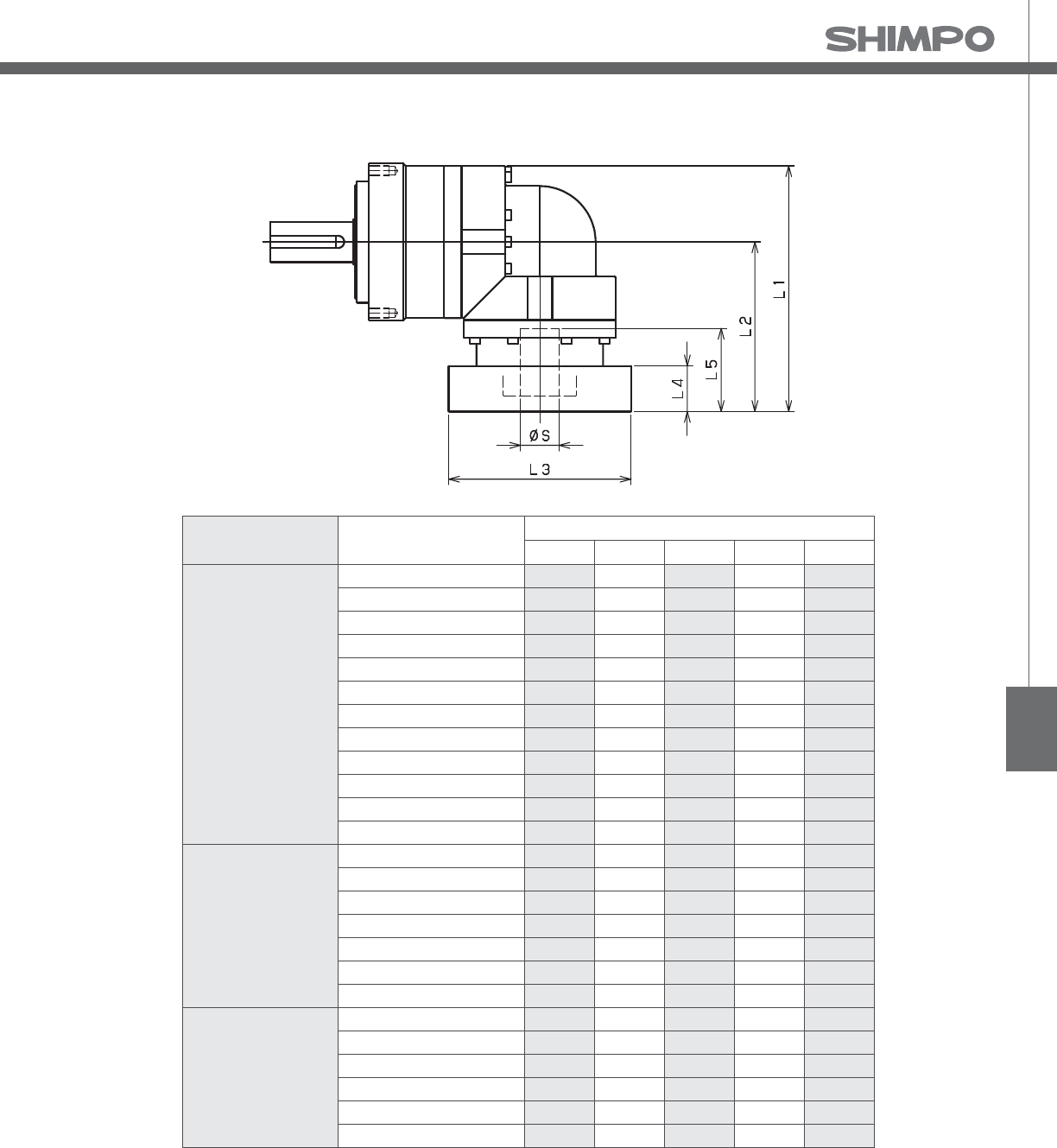
EVL
EVL- 3-Stage Adapter Dimensions
*1) Triple reduction : /~ /
*2) Bushing will be inserted to adapt to motor shaft
Model number **: Adapter code 3-Stage
L1 L2 L3 L4 L5
EVL-235-□-□-38**
(S≦ 38)
HA 344 231.5 □130 45 82
HB•HE 339 226.5 □130 40 77
JA 344 231.5 □150 45 82
KA•KB•KC 344 231.5 □180 45 82
KD 379 266.5 □180 80 117
KE 359 246.5 □180 60 97
LA 344 231.5 □200 45 82
LB 354 241.5 □200 55 92
MA•MB 344 231.5 □220 45 82
MC 359 246.5 □220 60 97
MD 354 241.5 □220 55 92
NA 344 231.5 □250 45 82
EVL-235-□-□-48**
(38 S≦ 48)
KA 380.5 268 □180 75 118
KB•KC 360.5 248 □180 55 98
LA 360.5 248 □200 55 98
MA 360.5 248 □220 55 98
MB 380.5 268 □220 75 118
NA 380.5 268 □250 75 118
PA 380.5 268 □280 75 118
EVL-235-□-□-65**
(48 S≦ 65)
MA•MB•MC•MD -- -- -- -- --
NA•NC -- -- -- -- --
NB•ND -- -- -- -- --
PA -- -- -- -- --
PB -- -- -- -- --
QA•QB -- -- -- -- --
A more comprehensive adapter ange o ering can be found using the NIDECSHIMPO Online Selector Tool. The variety is constantly
expanding and being updated on the Selector Tool. If you have any questions or need any support, contact NIDECSHIMPO.
For an explanation on the Adapter Flange Code, please turn to page .

This gearbox series is the right-angle version of the VRB, offer-
ing a compact configuration and output design that provides
an OEM with maximum versatility. The through-bolt flange design
at the output makes it much easier to assemble the reducer onto
machinery. A : spiral bevel gear for the right-angle connection
maintains good positional accuracy at ratios ranging from : – :.
The EVB units will have a minimum backlash of arc-minutes and
maximum loads approaching NM.
Equipment manufacturers building custom assembly automation sys-
tems will nd the exibility and space-saving features of the EVB an ideal
t for their unique projects. The EVB provides an excellent option when
performance, space, and cost all equally impact your reducer selection.
EVB-SERIES
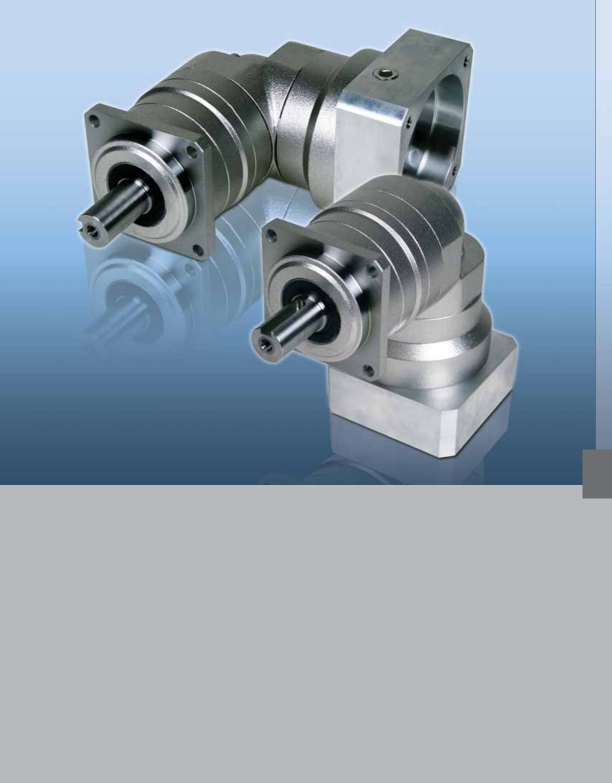
EVB-SERIES
■Industry standard mounting dimensions
■Large variety of reduction ratios to choose from
■Thru-bolt mounting style
■Maximum exibility for mounting and clearance constraints
■Low backlash (≤ arc-min)
■Space-saving design, when minimal envelope required
■Readily available
EVB

EVB-SERIES Right-angle shaft
EVB-Series Features
1 Space–saving features; motor can be located at a degree position from the reducer providing a more
compact footprint
2 High rigidity and torque capacity are achieved by using uncaged needle roller bearings
3 Adapter-bushing connection; enable a simple, e ective attachment to most servo motors
4 No leakage through the seal; high viscosity, anti-separation grease does not liquefy and does not migrate
away from the gears
5 No need to replace the grease for the life of the unit. The reducer can be positioned in any orientation
4
2
3
1

EVB
EVB-Series Model Code
㩷Adapter ange code
EV
B7090 −− − K 6 19HB16−
Backlash
060, 090, 115, 140
4 arc-min (2stage), 7 arc-min (3stage)
180, 220
6 arc-min (2stage), 9 arc-min (3stage)
2stage: 3, 4, 5, 6, 7, 8, 9, 10
3stage: 15, 16, 20, 25, 28, 30, 35, 40, 45, 50, 60, 70, 80, 90, 100
Output style K・・・ Shaft with key
S・・・ Smooth shaft
Ratio
Frame size 060, 090, 115, 140, 180, 220
Model name for ABLE reducer
Series name EVB Series
*1) Adapter ange code
Adapter ange code varies depending on the motor.
Contact us for additional information or refer to our online reducer selection tool.
Selection tool www.nidec-shimpo.co.jp/selection/eng

EVB-SERIES Right-angle shaft
Frame Size 060
Stage 2-Stage
Ratio Unit Note 3 4 5 6 7 8 9 10
Nominal Output Torque [Nm] *1 12 16 22 24 24 24 16 16
Maximum Acceleration Torque [Nm] *2 24 32 40 45 45 45 32 32
Emergency Stop Torque [Nm] *3 50 65 80 90 90 90 65 65
Nominal Input Speed [rpm] *4 3000
Maximum Input Speed [rpm] *5 6000
No Load Running Torque [Nm] *6 0.33
Permitted Radial Load [N] *7 430 470 510 540 570 600 620 640
Permitted Axial Load [N] *8 310 360 390 430 460 480 510 530
Maximum Radial Load [N] *9 1200
Maximum Axial Load [N] *10 1100
Moment of Inertia (≤ Ø 8) [kgcm2] -- 0.310 0.270 0.250 0.240 0.230 0.230 0.230 0.230
Moment of Inertia (≤ Ø 14) [kgcm2] -- 0.390 0.340 0.320 0.310 0.310 0.310 0.300 0.300
Moment of Inertia (≤ Ø 19) [kgcm2] -- 0.580 0.530 0.510 0.500 0.500 0.500 0.490 0.490
E ciency [%] *11 93
Torsional Rigidity [Nm/arc-min] *12 3
Maximum Torsional Backlash [arc-min] -- ≤ 4
Noise Level [dB] *13 80
Protection Class -- *14 IP54 (IP65)
Ambient Temperature [°C] -- 0-40
Permitted Housing Temperature [°C] -- 90
Weight [kg] *15 1.8
EVB- 2-Stage Specifications
EVB- 3-Stage Specifications
Frame Size 060
Stage 3-Stage
Ratio Unit Note 15 16 20 25 28 30 35 40
Nominal Output Torque [Nm] *1 16 24 24 24 24 16 24 24
Maximum Acceleration Torque [Nm] *2 32 45 45 45 45 32 45 45
Emergency Stop Torque [Nm] *3 65 90 90 90 90 65 90 90
Nominal Input Speed [rpm] *4 3000
Maximum Input Speed [rpm] *5 6000
No Load Running Torque [Nm] *6 0.20
Permitted Radial Load [N] *7 740 750 810 870 910 930 980 1000
Permitted Axial Load [N] *8 630 650 720 790 830 860 920 970
Maximum Radial Load [N] *9 1200
Maximum Axial Load [N] *10 1100
Moment of Inertia (≤ Ø 8) [kgcm2] -- 0.073 0.079 0.071 0.071 0.077 0.062 0.070 0.061
Moment of Inertia (≤ Ø 14) [kgcm2] -- 0.118 0.124 0.116 0.115 0.122 0.106 0.115 0.106
Moment of Inertia (≤ Ø 19) [kgcm2] -- -- -- -- -- -- -- -- --
E ciency [%] *11 88
Torsional Rigidity [Nm/arc-min] *12 3
Maximum Torsional Backlash [arc-min] -- ≤ 7
Noise Level [dB] *13 80
Protection Class -- *14 IP54 (IP65)
Ambient Temperature [°C] -- 0-40
Permitted Housing Temperature [°C] -- 90
Weight [kg] *15 1.6

EVB
EVB- 3-Stage Specifications
Frame Size 060
Stage 3-Stage
Ratio Unit Note 45 50 60 70 80 90 100
Nominal Output Torque [Nm] *1 16 24 24 24 24 16 16
Maximum Acceleration Torque [Nm] *2 32 45 45 45 45 32 32
Emergency Stop Torque [Nm] *3 65 90 90 90 90 65 65
Nominal Input Speed [rpm] *4 3000
Maximum Input Speed [rpm] *5 6000
No Load Running Torque [Nm] *6 0.20
Permitted Radial Load [N] *7 1100 1100 1200 1200 1200 1200 1200
Permitted Axial Load [N] *8 1000 1100 1100 1100 1100 1100 1100
Maximum Radial Load [N] *9 1200
Maximum Axial Load [N] *10 1100
Moment of Inertia (≤ Ø 8) [kgcm2] -- 0.070 0.061 0.061 0.061 0.061 0.061 0.061
Moment of Inertia (≤ Ø 14) [kgcm2] -- 0.115 0.106 0.106 0.105 0.105 0.105 0.105
Moment of Inertia (≤ Ø 19) [kgcm2] -- -- -- -- -- -- -- --
E ciency [%] *11 88
Torsional Rigidity [Nm/arc-min] *12 3
Maximum Torsional Backlash [arc-min] -- ≤ 7
Noise Level [dB] *13 80
Protection Class -- *14 IP54 (IP65)
Ambient Temperature [°C] -- 0-40
Permitted Housing Temperature [°C] -- 90
Weight [kg] *15 1.6
*1) At nominal input speed, service life is , hours
*2) The maximum torque when starting or stopping operation
*3) The maximum torque allowed under a stress situation (Permitted , times during service life)
*4) The average input speed
*5) The maximum intermittent input speed
*6) This is the torque at no load applied on the input shaft. The input speed is rpm for EVB
*7) At this load and nominal input speed, service life will be , hours. (The radial load applied to the output side bearing)
*8) At this load and nominal input speed, service life will be , hours. (The axial load applied to the output shaft center)
*9) The maximum radial load that the reducer can accept
*10) The maximum axial load that the reducer can accept
*11) The e ciency at the nominal torque rating
*12) This does not include the lost motion
*13) Contact NIDEC-SHIMPO for the testing conditions and environment
*14) IP (wash-down) is available as an option. Contact NIDECSHIMPO for more details and our food grade options
*15) The weight may vary slightly between models

EVB-SERIES Right-angle shaft
EVB- 2-Stage Dimensions
*1) Length will vary depending on motor
*2) Bushing will be inserted to adapt to motor shaft

EVB
EVB- 3-Stage Dimensions
*1) Length will vary depending on motor
*2) Bushing will be inserted to adapt to motor shaft

EVB-SERIES Right-angle shaft
EVB- 2-Stage Adapter Dimensions
*1) Double reduction : /~ /
*2) Bushing will be inserted to adapt to motor shaft
Model number **: Adapter code 2-Stage
L1 L2 L3 L4 L5
EVB-060-□-□-8**
(S≦ 8)
AA•AC•AD•AF•AG•AL•AM•AN•AQ 103 71.5 □52 15.5 32
AB•AE•AH•AJ•AK 108 76.5 □52 20.5 37
BA•BB•BD•BE•BG•BH•BJ 103 71.5 □60 15.5 32
BC•BF 108 76.5 □60 20.5 37
CA 108 76.5 □70 20.5 37
EVB-060-□-□-14**
(8 S≦ 14)
BA•BB•BD•BE•BF•BG•BH•BJ•BK•BP 109 77.5 □65 16.5 35
BC•BH•BM•BN 114 82.5 □65 21.5 40
BL 119 87.5 □65 26.5 45
CA•CC 109 77.5 □70 16.5 35
CB 114 82.5 □70 21.5 40
DA•DB•DC•DD•DF•DH•DJ 109 77.5 □80 16.5 35
DE•DL 114 82.5 □80 21.5 40
DG•DK 119 87.5 □80 26.5 45
EA•EB•EC•EF•EG•EK•EL 109 77.5 □90 16.5 35
EJ•EM 114 82.5 □90 21.5 40
ED•EE•EH 119 87.5 □90 26.5 45
FA 109 77.5 □100 16.5 35
FB 119 87.5 □100 26.5 45
EVB-060-□-□-19**
(14 S≦19)
DA•DB•DC 126 94.5 □80 25 50
DD 136 104.5 □80 35 60
DE 131 99.5 □80 30 55
EA 131 99.5 □90 30 55
EB•ED 126 94.5 □90 25 50
EC 136 104.5 □90 35 60
FA 126 94.5 □100 25 50
FB 136 104.5 □100 35 60
A more comprehensive adapter ange o ering can be found using the NIDECSHIMPO Online Selector Tool. The variety is constantly
expanding and being updated on the Selector Tool. If you have any questions or need any support, contact NIDECSHIMPO.
For an explanation on the Adapter Flange Code, please turn to page .

EVB
EVB- 3-Stage Adapter Dimensions
*1) Triple reduction : /~ /
*2) Bushing will be inserted to adapt to motor shaft
Model number **: Adapter code 3-Stage
L1 L2 L3 L4 L5
EVB-060-□-□-8**
(S≦ 8)
AA•AC•AD•AF•AG•AL•AM•AN•AQ 96 64.5 □52 15.5 32
AB•AE•AH•AJ•AK 101 69.5 □52 20.5 37
BA•BB•BD•BE•BG•BH•BJ 96 64.5 □60 15.5 32
BC•BF 101 69.5 □60 20.5 37
CA 101 69.5 □70 20.5 37
EVB-060-□-□-14**
(8 S≦ 14)
BA•BB•BD•BE•BF•BG•BH•BJ•BK•BP 100 68.5 □65 16.5 35
BC•BH•BM•BN 105 73.5 □65 21.5 40
BL 110 78.5 □65 26.5 45
CA•CC 100 68.5 □70 16.5 35
CB 105 73.5 □70 21.5 40
DA•DB•DC•DD•DF•DH•DJ 100 68.5 □80 16.5 35
DE•DL 105 73.5 □80 21.5 40
DG•DK 110 78.5 □80 26.5 45
EA•EB•EC•EF•EG•EK•EL 100 68.5 □90 16.5 35
EJ•EM 105 73.5 □90 21.5 40
ED•EE•EH 110 78.5 □90 26.5 45
FA 100 68.5 □100 16.5 35
FB 110 78.5 □100 26.5 45
EVB-060-□-□-19**
(14 S≦19)
DA•DB•DC -- -- -- -- --
DD -- -- -- -- --
DE -- -- -- -- --
EA -- -- -- -- --
EB•ED -- -- -- -- --
EC -- -- -- -- --
FA -- -- -- -- --
FB -- -- -- -- --
A more comprehensive adapter ange o ering can be found using the NIDECSHIMPO Online Selector Tool. The variety is constantly
expanding and being updated on the Selector Tool. If you have any questions or need any support, contact NIDECSHIMPO.
For an explanation on the Adapter Flange Code, please turn to page .

EVB-SERIES Right-angle shaft
EVB- 2-Stage Specifications
EVB- 3-Stage Specifications
Frame Size 090
Stage 2-Stage
Ratio Unit Note 3 4 5 6 7 8 9 10
Nominal Output Torque [Nm] *1 45 60 65 65 65 65 45 45
Maximum Acceleration Torque [Nm] *2 65 90 90 90 90 90 65 65
Emergency Stop Torque [Nm] *3 130 170 220 220 220 220 170 170
Nominal Input Speed [rpm] *4 3000
Maximum Input Speed [rpm] *5 6000
No Load Running Torque [Nm] *6 1.13
Permitted Radial Load [N] *7 810 890 960 1000 1100 1100 1200 1200
Permitted Axial Load [N] *8 930 1100 1200 1300 1300 1400 1500 1600
Maximum Radial Load [N] *9 2400
Maximum Axial Load [N] *10 2200
Moment of Inertia (≤ Ø 8) [kgcm2] -- -- -- -- -- -- -- -- --
Moment of Inertia (≤ Ø 14) [kgcm2] -- 2.120 1.890 1.800 1.760 1.730 1.710 1.700 1.690
Moment of Inertia (≤ Ø 19) [kgcm2] -- 2.450 2.220 2.130 2.090 2.060 2.040 2.030 2.020
Moment of Inertia (≤ Ø 28) [kgcm2] -- 4.570 4.350 4.260 4.210 4.180 4.170 4.160 4.150
E ciency [%] *11 93
Torsional Rigidity [Nm/arc-min] *12 10
Maximum Torsional Backlash [arc-min] -- ≤ 4
Noise Level [dB] *13 80
Protection Class -- *14 IP54 (IP65)
Ambient Temperature [°C] -- 0-40
Permitted Housing Temperature [°C] -- 90
Weight [kg] *15 5.1
Frame Size 090
Stage 3-Stage
Ratio Unit Note 15 16 20 25 28 30 35 40
Nominal Output Torque [Nm] *1 45 65 65 65 65 45 65 65
Maximum Acceleration Torque [Nm] *2 65 110 110 110 110 65 110 110
Emergency Stop Torque [Nm] *3 170 220 220 220 220 170 220 220
Nominal Input Speed [rpm] *4 3000
Maximum Input Speed [rpm] *5 6000
No Load Running Torque [Nm] *6 0.55
Permitted Radial Load [N] *7 1400 1400 1500 1600 1700 1700 1800 1900
Permitted Axial Load [N] *8 1900 1900 2100 2200 2200 2200 2200 2200
Maximum Radial Load [N] *9 2400
Maximum Axial Load [N] *10 2200
Moment of Inertia (≤ Ø 8) [kgcm2] -- 0.340 0.380 0.330 0.320 0.370 0.250 0.320 0.250
Moment of Inertia (≤ Ø 14) [kgcm2] -- 0.410 0.460 0.400 0.400 0.450 0.330 0.400 0.320
Moment of Inertia (≤ Ø 19) [kgcm2] -- 0.600 0.650 0.590 0.590 0.640 0.510 0.590 0.510
Moment of Inertia (≤ Ø 28) [kgcm2] -- -- -- -- -- -- -- -- --
E ciency [%] *11 88
Torsional Rigidity [Nm/arc-min] *12 10
Maximum Torsional Backlash [arc-min] -- ≤ 7
Noise Level [dB] *13 80
Protection Class -- *14 IP54 (IP65)
Ambient Temperature [°C] -- 0-40
Permitted Housing Temperature [°C] -- 90
Weight [kg] *15 4.4
EVB
EVB- 3-Stage Specifications
Frame Size 090
Stage 3-Stage
Ratio Unit Note 45 50 60 70 80 90 100
Nominal Output Torque [Nm] *1 45 65 65 65 65 45 45
Maximum Acceleration Torque [Nm] *2 65 110 110 110 110 65 65
Emergency Stop Torque [Nm] *3 170 220 220 220 220 170 170
Nominal Input Speed [rpm] *4 3000
Maximum Input Speed [rpm] *5 6000
No Load Running Torque [Nm] *6 0.55
Permitted Radial Load [N] *7 2000 2100 2200 2300 2400 2400 2400
Permitted Axial Load [N] *8 2200 2200 2200 2200 2200 2200 2200
Maximum Radial Load [N] *9 2400
Maximum Axial Load [N] *10 2200
Moment of Inertia (≤ Ø 8) [kgcm2] -- 0.320 0.250 0.250 0.250 0.250 0.250 0.250
Moment of Inertia (≤ Ø 14) [kgcm2] -- 0.390 0.320 0.320 0.320 0.320 0.320 0.320
Moment of Inertia (≤ Ø 19) [kgcm2] -- 0.580 0.510 0.510 0.510 0.510 0.510 0.510
Moment of Inertia (≤ Ø 28) [kgcm2] -- -- -- -- -- -- -- --
E ciency [%] *11 88
Torsional Rigidity [Nm/arc-min] *12 10
Maximum Torsional Backlash [arc-min] -- ≤ 7
Noise Level [dB] *13 80
Protection Class -- *14 IP54 (IP65)
Ambient Temperature [°C] -- 0-40
Permitted Housing Temperature [°C] -- 90
Weight [kg] *15 4.4
*1) At nominal input speed, service life is , hours
*2) The maximum torque when starting or stopping operation
*3) The maximum torque allowed under a stress situation (Permitted , times during service life)
*4) The average input speed
*5) The maximum intermittent input speed
*6) This is the torque at no load applied on the input shaft. The input speed is rpm for EVB
*7) At this load and nominal input speed, service life will be , hours. (The radial load applied to the output side bearing)
*8) At this load and nominal input speed, service life will be , hours. (The axial load applied to the output shaft center)
*9) The maximum radial load that the reducer can accept
*10) The maximum axial load that the reducer can accept
*11) The e ciency at the nominal torque rating
*12) This does not include the lost motion
*13) Contact NIDEC-SHIMPO for the testing conditions and environment
*14) IP (wash-down) is available as an option. Contact NIDECSHIMPO for more details and our food grade options
*15) The weight may vary slightly between models
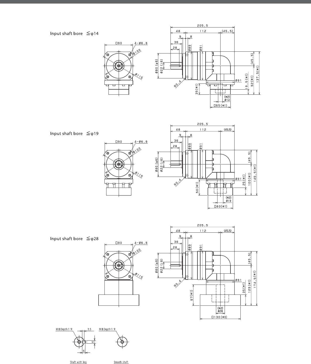
EVB-SERIES Right-angle shaft
EVB- 2-Stage Dimensions
*1) Length will vary depending on motor
*2) Bushing will be inserted to adapt to motor shaft

EVB
EVB- 3-Stage Dimensions
*1) Length will vary depending on motor
*2) Bushing will be inserted to adapt to motor shaft

EVB-SERIES Right-angle shaft
EVB- 2-Stage Adapter Dimensions
*1) Double reduction : /~ /
Model number **: Adapter code 2-Stage
L1 L2 L3 L4 L5
EVB-090-□-□-8**
(S≦ 8)
AA•AC•AD•AF•AG•AL•AM•AN•AQ -- -- -- -- --
AB•AE•AH•AJ•AK -- -- -- -- --
BA•BB•BD•BE•BG•BH•BJ -- -- -- -- --
CA -- -- -- -- --
EVB-090-□-□-14**
(8 S≦ 14)
BA•BB•BD•BE•BF•BG•BH•BJ•BK•BP 137.5 92 □65 16.5 35
BC•BH•BM•BN 142.5 97 □65 21.5 40
CA•CC 137.5 92 □70 16.5 35
DA•DB•DC•DD•DF•DH•DJ 137.5 92 □80 16.5 35
EA•EB•EC•EF•EG•EK•EL 137.5 92 □90 16.5 35
FA 137.5 92 □100 16.5 35
FB 147.5 102 □100 26.5 45
JA 152.5 107 □150 31.5 50
EVB-090-□-□-19**
(14 S≦ 19)
DA•DB•DC 145.5 100 □80 25 50
EB•ED 145.5 100 □90 25 50
FA 145.5 100 □100 25 50
FB 155.5 110 □100 35 60
GA•GC•GH 150.5 105 □115 30 55
GB•GD•GJ 145.5 100 □115 25 50
GE•GF 155.5 110 □115 35 60
HA 145.5 100 □130 25 50
HB 160.5 115 □130 40 65
HC•HD•HE 150.5 105 □130 30 55
JA 155.5 110 □150 35 60
JB 160.5 115 □150 40 65
EVB-090-□-□-28**
(19 S≦ 28)
FA•FB•FC 174.5 129 □100 35 67
FD•FE 169.5 124 □100 30 62
GA•GB•GC•GD•GE•GF•GG•GH 174.5 129 □115 35 67
HA•HC•HD 174.5 129 □130 35 67
HB 184.5 139 □130 45 77
HE 189.5 144 □130 50 82
HF 169.5 124 □130 30 62
JA•JB•JC•JF 174.5 129 □150 35 67
JD 194.5 149 □150 55 87
JE 184.5 139 □150 45 77
A more comprehensive adapter ange o ering can be found using the NIDECSHIMPO Online Selector Tool. The variety is constantly
expanding and being updated on the Selector Tool. If you have any questions or need any support, contact NIDECSHIMPO.
For an explanation on the Adapter Flange Code, please turn to page .
*) Bushing will be inserted to adapt to motor shaft
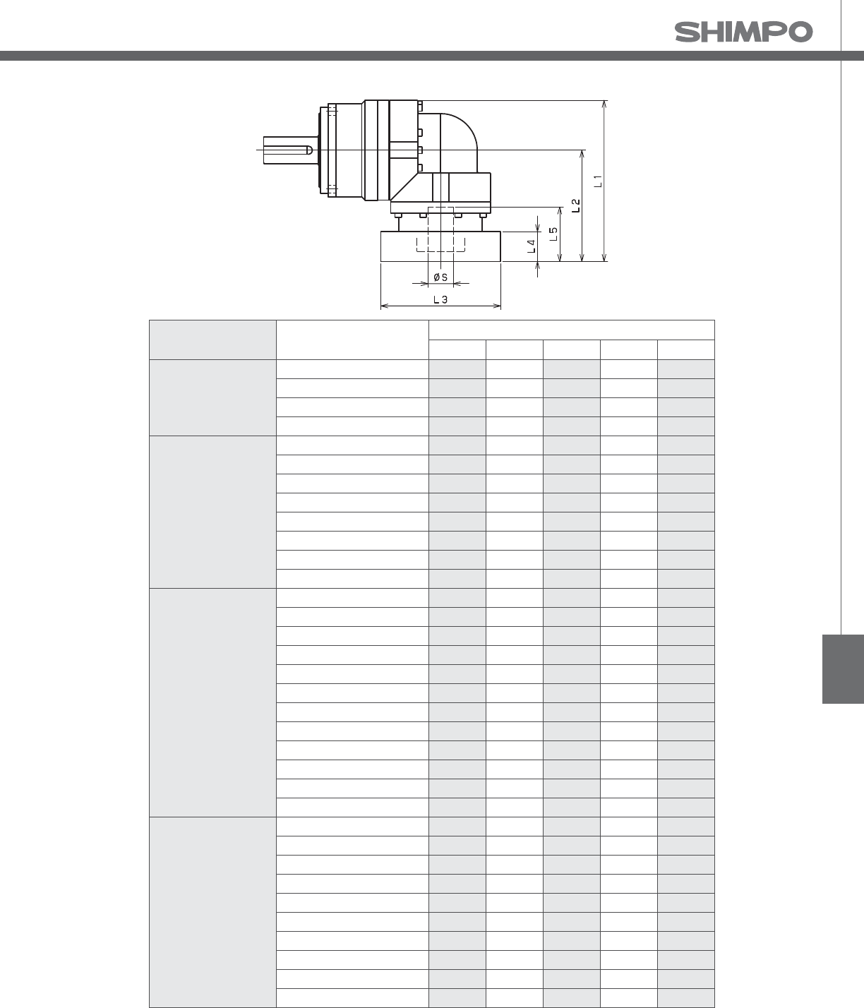
EVB
EVB- 3-Stage Adapter Dimensions
*1) Triple reduction : /~ /
Model number **: Adapter code 3-Stage
L1 L2 L3 L4 L5
EVB-090-□-□-8**
(S≦ 8)
AA•AC•AD•AF•AG•AL•AM•AN•AQ 117 71.5 □52 15.5 32
AB•AE•AH•AJ•AK 122 76.5 □52 20.5 37
BA•BB•BD•BE•BG•BH•BJ 117 71.5 □60 15.5 32
CA 122 76.5 □70 20.5 37
EVB-090-□-□-14**
(8 S≦ 14)
BA•BB•BD•BE•BF•BG•BH•BJ•BK•BP 123 77.5 □65 16.5 35
BC•BH•BM•BN 128 82.5 □65 21.5 40
CA•CC 123 77.5 □70 16.5 35
DA•DB•DC•DD•DF•DH•DJ 123 77.5 □80 16.5 35
EA•EB•EC•EF•EG•EK•EL 123 77.5 □90 16.5 35
FA 123 77.5 □100 16.5 35
FB 133 87.5 □100 26.5 45
JA 138 92.5 □150 31.5 50
EVB-090-□-□-19**
(14 S≦ 19)
DA•DB•DC 140 94.5 □80 25 50
EB•ED 140 94.5 □90 25 50
FA 140 94.5 □100 25 50
FB 150 104.5 □100 35 60
GA•GC•GH 145 99.5 □115 30 55
GB•GD•GJ 140 94.5 □115 25 50
GE•GF 150 104.5 □115 35 60
HA 140 94.5 □130 25 50
HB 155 109.5 □130 40 65
HC•HD•HE 145 99.5 □130 30 55
JA 150 104.5 □150 35 60
JB 155 109.5 □150 40 65
EVB-090-□-□-28**
(19 S≦ 28)
FA•FB•FC -- -- -- -- --
FD•FE -- -- -- -- --
GA•GB•GC•GD•GE•GF•GG•GH -- -- -- -- --
HA•HC•HD -- -- -- -- --
HB -- -- -- -- --
HE -- -- -- -- --
HF -- -- -- -- --
JA•JB•JC•JF -- -- -- -- --
JD -- -- -- -- --
JE -- -- -- -- --
A more comprehensive adapter ange o ering can be found using the NIDECSHIMPO Online Selector Tool. The variety is constantly
expanding and being updated on the Selector Tool. If you have any questions or need any support, contact NIDECSHIMPO.
For an explanation on the Adapter Flange Code, please turn to page .
*) Bushing will be inserted to adapt to motor shaft

EVB-SERIES Right-angle shaft
EVB- 2-Stage Specifications
EVB- 3-Stage Specifications
Frame Size 115
Stage 2-Stage
Ratio Unit Note 3 4 5 6 7 8 9 10
Nominal Output Torque [Nm] *1 75 100 120 150 150 150 110 110
Maximum Acceleration Torque [Nm] *2 150 200 240 300 300 300 200 200
Emergency Stop Torque [Nm] *3 320 430 500 550 550 550 450 450
Nominal Input Speed [rpm] *4 3000
Maximum Input Speed [rpm] *5 6000
No Load Running Torque [Nm] *6 1.88
Permitted Radial Load [N] *7 1300 1500 1600 1700 1800 1900 1900 2000
Permitted Axial Load [N] *8 1500 1700 1900 2000 2100 2300 2400 2500
Maximum Radial Load [N] *9 4300
Maximum Axial Load [N] *10 3900
Moment of Inertia (≤ Ø 14) [kgcm2] -- -- -- -- -- -- -- -- --
Moment of Inertia (≤ Ø 19) [kgcm2] -- 6.740 5.490 5.020 4.770 4.650 4.550 4.490 4.460
Moment of Inertia (≤ Ø 28) [kgcm2] -- 8.340 7.080 6.610 6.360 6.240 6.140 6.080 6.050
Moment of Inertia (≤ Ø 38) [kgcm2] -- 15.410 14.150 13.690 13.430 13.310 13.220 13.160 13.120
E ciency [%] *11 93
Torsional Rigidity [Nm/arc-min] *12 31
Maximum Torsional Backlash [arc-min] -- ≤ 4
Noise Level [dB] *13 85
Protection Class -- *14 IP54 (IP65)
Ambient Temperature [°C] -- 0-40
Permitted Housing Temperature [°C] -- 90
Weight [kg] *15 10.4
Frame Size 115
Stage 3-Stage
Ratio Unit Note 15 16 20 25 28 30 35 40
Nominal Output Torque [Nm] *1 110 130 150 150 150 110 150 150
Maximum Acceleration Torque [Nm] *2 200 260 300 300 300 200 300 300
Emergency Stop Torque [Nm] *3 450 550 550 550 550 450 550 550
Nominal Input Speed [rpm] *4 3000
Maximum Input Speed [rpm] *5 6000
No Load Running Torque [Nm] *6 1.11
Permitted Radial Load [N] *7 2300 2300 2500 2700 2800 2900 3000 3200
Permitted Axial Load [N] *8 3000 3100 3400 3700 3900 3900 3900 3900
Maximum Radial Load [N] *9 3900
Maximum Axial Load [N] *10 3900
Moment of Inertia (≤ Ø 14) [kgcm2] -- 2.250 2.460 2.200 2.180 2.400 1.870 2.160 1.860
Moment of Inertia (≤ Ø 19) [kgcm2] -- 2.580 2.790 2.530 2.510 2.730 2.200 2.490 2.190
Moment of Inertia (≤ Ø 28) [kgcm2] -- 4.700 4.910 4.650 4.640 4.860 4.330 4.620 4.320
Moment of Inertia (≤ Ø 38) [kgcm2] -- -- -- -- -- -- -- -- --
E ciency [%] *11 88
Torsional Rigidity [Nm/arc-min] *12 31
Maximum Torsional Backlash [arc-min] -- ≤ 7
Noise Level [dB] *13 85
Protection Class -- *14 IP54 (IP65)
Ambient Temperature [°C] -- 0-40
Permitted Housing Temperature [°C] -- 90
Weight [kg] *15 10.1

EVB
EVB- 3-Stage Specifications
Frame Size 115
Stage 3-Stage
Ratio Unit Note 45 50 60 70 80 90 100
Nominal Output Torque [Nm] *1 110 150 150 150 150 110 110
Maximum Acceleration Torque [Nm] *2 200 300 300 300 300 200 200
Emergency Stop Torque [Nm] *3 450 550 550 550 550 450 450
Nominal Input Speed [rpm] *4 3000
Maximum Input Speed [rpm] *5 6000
No Load Running Torque [Nm] *6 1.11
Permitted Radial Load [N] *7 3300 3400 3600 3800 4000 4200 4300
Permitted Axial Load [N] *8 3900 3900 3900 3900 3900 3900 3900
Maximum Radial Load [N] *9 4300
Maximum Axial Load [N] *10 3900
Moment of Inertia (≤ Ø 14) [kgcm2] -- 2.150 1.860 1.850 1.850 1.850 1.850 1.850
Moment of Inertia (≤ Ø 19) [kgcm2] -- 2.480 2.190 2.180 2.180 2.180 2.180 2.180
Moment of Inertia (≤ Ø 28) [kgcm2] -- 4.610 4.310 4.310 4.310 4.310 4.310 4.310
Moment of Inertia (≤ Ø 38) [kgcm2] -- -- -- -- -- -- -- --
E ciency [%] *11 88
Torsional Rigidity [Nm/arc-min] *12 31
Maximum Torsional Backlash [arc-min] -- ≤ 7
Noise Level [dB] *13 85
Protection Class -- *14 IP54 (IP65)
Ambient Temperature [°C] -- 0-40
Permitted Housing Temperature [°C] -- 90
Weight [kg] *15 10.1
*1) At nominal input speed, service life is , hours
*2) The maximum torque when starting or stopping operation
*3) The maximum torque allowed under a stress situation (Permitted , times during service life)
*4) The average input speed
*5) The maximum intermittent input speed
*6) This is the torque at no load applied on the input shaft. The input speed is rpm for EVB
*7) At this load and nominal input speed, service life will be , hours. (The radial load applied to the output side bearing)
*8) At this load and nominal input speed, service life will be , hours. (The axial load applied to the output shaft center)
*9) The maximum radial load that the reducer can accept
*10) The maximum axial load that the reducer can accept
*11) The e ciency at the nominal torque rating
*12) This does not include the lost motion
*13) Contact NIDEC-SHIMPO for the testing conditions and environment
*14) IP (wash-down) is available as an option. Contact NIDECSHIMPO for more details and our food grade options
*15) The weight may vary slightly between models

EVB-SERIES Right-angle shaft
EVB- 2-Stage Dimensions
*1) Length will vary depending on motor
*2) Bushing will be inserted to adapt to motor shaft

EVB
EVB- 3-Stage Dimensions
*1) Length will vary depending on motor
*2) Bushing will be inserted to adapt to motor shaft

EVB-SERIES Right-angle shaft
EVB- 2-Stage Adapter Dimensions
*1) Double reduction : /~ /
Model number **: Adapter code 2-Stage
L1 L2 L3 L4 L5
EVB-115-□-□-14**
(S≦ 14)
BA•BB•BD•BE•BF•BG•BH•BJ•BK•BP -- -- -- -- --
BC•BH•BM•BN -- -- -- -- --
CA•CC ----------
DA•DB•DC•DD•DF•DH•DJ -- -- -- -- --
EA•EB•EC•EF•EG•EK•EL -- -- -- -- --
FA -- -- -- -- --
FB -- -- -- -- --
JA -- -- -- -- --
EVB-115-□-□-19**
(14 S≦ 19)
DA•DB•DC 170 110 □80 25 50
EB•ED 170 110 □90 25 50
FA 170 110 □100 25 50
FB 180 120 □100 35 60
GB•GD•GJ 170 110 □115 25 50
HA 170 110 □130 25 50
HB 185 125 □130 40 65
JA 180 120 □150 35 60
EVB-115-□-□-28**
(19 S≦ 28)
FA•FB•FC 196 136 □100 35 67
FD•FE 191 131 □100 30 62
GA•GB•GC•GD•GE•GF•GG•GH 196 136 □115 35 67
HA•HC•HD 196 136 □130 35 67
HB 206 146 □130 45 77
HE 211 151 □130 50 82
HF 191 131 □130 30 62
JA•JB•JC•JF 196 136 □150 35 67
JD 216 156 □150 55 87
JE 206 146 □150 45 77
KA•KB•KE 196 136 □180 35 67
KD 206 146 □180 45 77
EVB-115-□-□-38**
(28 S≦ 38)
HA 213 153 □130 45 82
HB•HE 208 148 □130 40 77
JA 213 153 □150 45 82
KA•KB•KC 213 153 □180 45 82
KD 248 188 □180 80 117
KE 228 168 □180 60 97
A more comprehensive adapter ange o ering can be found using the NIDECSHIMPO Online Selector Tool. The variety is constantly
expanding and being updated on the Selector Tool. If you have any questions or need any support, contact NIDECSHIMPO.
For an explanation on the Adapter Flange Code, please turn to page .
*) Bushing will be inserted to adapt to motor shaft

EVB
EVB- 3-Stage Adapter Dimensions
*1) Triple reduction : /~ /
Model number **: Adapter code 3-Stage
L1 L2 L3 L4 L5
EVB-115-□-□-14**
(S≦ 14)
BA•BB•BD•BE•BF•BG•BH•BJ•BK•BP 152 92 □65 16.5 35
BC•BH•BM•BN 157 97 □65 21.5 40
CA•CC 152 92 □70 16.5 35
DA•DB•DC•DD•DF•DH•DJ 152 92 □80 16.5 35
EA•EB•EC•EF•EG•EK•EL 152 92 □90 16.5 35
FA 152 92 □100 16.5 35
FB 162 102 □100 26.5 45
JA 167 107 □150 31.5 50
EVB-115-□-□-19**
(14 S≦ 19)
DA•DB•DC 160 100 □80 25 50
EB•ED 160 100 □90 25 50
FA 160 100 □100 25 50
FB 170 110 □100 35 60
GB•GD•GJ 160 100 □115 25 50
HA 160 100 □130 25 50
HB 175 115 □130 40 65
JA 170 110 □150 35 60
EVB-115-□-□-28**
(19 S≦ 28)
FA•FB•FC 189 129 □100 35 67
FD•FE 184 124 □100 30 62
GA•GB•GC•GD•GE•GF•GG•GH 189 129 □115 35 67
HA•HC•HD 189 129 □130 35 67
HB 199 139 □130 45 77
HE 204 144 □130 50 82
HF 184 124 □130 30 62
JA•JB•JC•JF 189 129 □150 35 67
JD 209 149 □150 55 87
JE 199 139 □150 45 77
KA•KB•KE 189 129 □180 35 67
KD 199 139 □180 45 77
EVB-115-□-□-38**
(28 S≦ 38)
HA -- -- -- -- --
HB•HE -- -- -- -- --
JA -- -- -- -- --
KA•KB•KC -- -- -- -- --
KD -- -- -- -- --
KE -- -- -- -- --
A more comprehensive adapter ange o ering can be found using the NIDECSHIMPO Online Selector Tool. The variety is constantly
expanding and being updated on the Selector Tool. If you have any questions or need any support, contact NIDECSHIMPO.
For an explanation on the Adapter Flange Code, please turn to page .
*) Bushing will be inserted to adapt to motor shaft

EVB-SERIES Right-angle shaft
EVB- 2-Stage Specifications
EVB- 3-Stage Specifications
Frame Size 140
Stage 2-Stage
Ratio Unit Note 3 4 5 6 7 8 9 10
Nominal Output Torque [Nm] *1 130 170 200 260 300 300 200 200
Maximum Acceleration Torque [Nm] *2 260 340 400 520 600 600 400 400
Emergency Stop Torque [Nm] *3 700 950 1100 1100 1100 1100 750 750
Nominal Input Speed [rpm] *4 2000
Maximum Input Speed [rpm] *5 4000
No Load Running Torque [Nm] *6 3.26
Permitted Radial Load [N] *7 3200 3500 3800 4000 4200 4400 4600 4700
Permitted Axial Load [N] *8 2400 2700 3000 3300 3500 3700 3900 4100
Maximum Radial Load [N] *9 9100
Maximum Axial Load [N] *10 8200
Moment of Inertia (≤ Ø 19) [kgcm2] -- -- -- -- -- -- -- -- --
Moment of Inertia (≤ Ø 28) [kgcm2] -- 23.130 18.570 16.910 16.010 15.580 15.230 14.770 14.660
Moment of Inertia (≤ Ø 38) [kgcm2] -- 27.500 22.940 21.280 20.380 19.950 19.610 19.410 19.030
Moment of Inertia (≤ Ø 48) [kgcm2] -- 40.730 36.170 34.510 33.610 33.180 32.840 32.370 32.260
E ciency [%] *11 93
Torsional Rigidity [Nm/arc-min] *12 60
Maximum Torsional Backlash [arc-min] -- ≤ 4
Noise Level [dB] *13 85
Protection Class -- *14 IP54 (IP65)
Ambient Temperature [°C] -- 0-40
Permitted Housing Temperature [°C] -- 90
Weight [kg] *15 19.1
Frame Size 140
Stage 3-Stage
Ratio Unit Note 15 16 20 25 28 30 35 40
Nominal Output Torque [Nm] *1 200 300 300 300 300 200 300 300
Maximum Acceleration Torque [Nm] *2 400 600 600 600 600 400 600 600
Emergency Stop Torque [Nm] *3 750 1100 1100 1100 1100 750 1100 1100
Nominal Input Speed [rpm] *4 2000
Maximum Input Speed [rpm] *5 4000
No Load Running Torque [Nm] *6 2.56
Permitted Radial Load [N] *7 5400 5500 6000 6400 6700 6800 7200 7500
Permitted Axial Load [N] *8 4900 5000 5500 6100 6400 6600 7000 7500
Maximum Radial Load [N] *9 9100
Maximum Axial Load [N] *10 8200
Moment of Inertia (≤ Ø 19) [kgcm2] -- 6.400 7.290 6.220 6.150 7.090 4.990 6.090 4.950
Moment of Inertia (≤ Ø 28) [kgcm2] -- 8.000 8.880 7.810 7.750 8.680 6.580 7.690 6.540
Moment of Inertia (≤ Ø 38) [kgcm2] -- 15.070 15.960 14.890 14.820 15.760 13.660 14.760 13.610
Moment of Inertia (≤ Ø 48) [kgcm2] -- -- -- -- -- -- -- -- --
E ciency [%] *11 88
Torsional Rigidity [Nm/arc-min] *12 60
Maximum Torsional Backlash [arc-min] -- ≤ 7
Noise Level [dB] *13 85
Protection Class -- *14 IP54 (IP65)
Ambient Temperature [°C] -- 0-40
Permitted Housing Temperature [°C] -- 90
Weight [kg] *15 19.6

EVB
EVB- 3-Stage Specifications
Frame Size 140
Stage 3-Stage
Ratio Unit Note 45 50 60 70 80 90 100
Nominal Output Torque [Nm] *1 200 300 300 300 300 200 200
Maximum Acceleration Torque [Nm] *2 400 600 600 600 600 400 400
Emergency Stop Torque [Nm] *3 750 1100 1100 1100 1100 750 750
Nominal Input Speed [rpm] *4 2000
Maximum Input Speed [rpm] *5 4000
No Load Running Torque [Nm] *6 2.56
Permitted Radial Load [N] *7 7800 8100 8600 9100 9100 9100 9100
Permitted Axial Load [N] *8 7900 8200 8200 8200 8200 8200 8200
Maximum Radial Load [N] *9 9100
Maximum Axial Load [N] *10 8200
Moment of Inertia (≤ Ø 19) [kgcm2] -- 6.070 4.930 4.920 4.910 4.910 4.910 4.910
Moment of Inertia (≤ Ø 28) [kgcm2] -- 7.660 6.520 6.510 6.510 6.500 6.500 6.500
Moment of Inertia (≤ Ø 38) [kgcm2] -- 14.740 13.590 13.590 13.580 13.580 13.570 13.570
Moment of Inertia (≤ Ø 48) [kgcm2] -- -- -- -- -- -- -- --
E ciency [%] *11 88
Torsional Rigidity [Nm/arc-min] *12 60
Maximum Torsional Backlash [arc-min] -- ≤ 7
Noise Level [dB] *13 85
Protection Class -- *14 IP54 (IP65)
Ambient Temperature [°C] -- 0-40
Permitted Housing Temperature [°C] -- 90
Weight [kg] *15 19.6
*1) At nominal input speed, service life is , hours
*2) The maximum torque when starting or stopping operation
*3) The maximum torque allowed under a stress situation (Permitted , times during service life)
*4) The average input speed
*5) The maximum intermittent input speed
*6) This is the torque at no load applied on the input shaft. The input speed is rpm for EVB
*7) At this load and nominal input speed, service life will be , hours. (The radial load applied to the output side bearing)
*8) At this load and nominal input speed, service life will be , hours. (The axial load applied to the output shaft center)
*9) The maximum radial load that the reducer can accept
*10) The maximum axial load that the reducer can accept
*11) The e ciency at the nominal torque rating
*12) This does not include the lost motion
*13) Contact NIDEC-SHIMPO for the testing conditions and environment
*14) IP (wash-down) is available as an option. Contact NIDECSHIMPO for more details and our food grade options
*15) The weight may vary slightly between models

EVB-SERIES Right-angle shaft
EVB- 2-Stage Dimensions
*1) Length will vary depending on motor
*2) Bushing will be inserted to adapt to motor shaft

EVB
EVB- 3-Stage Dimensions
*1) Length will vary depending on motor
*2) Bushing will be inserted to adapt to motor shaft

EVB-SERIES Right-angle shaft
EVB- 2-Stage Adapter Dimensions
*1) Double reduction : /~ /
Model number **: Adapter code 2-Stage
L1 L2 L3 L4 L5
EVB-140-□-□-19**
(S≦ 19)
DA•DB•DC -- -- -- -- --
EB•ED -- -- -- -- --
FA -- -- -- -- --
FB -- -- -- -- --
GB•GD•GJ -- -- -- -- --
HA -- -- -- -- --
HB -- -- -- -- --
JA -- -- -- -- --
EVB-140-□-□-28**
(19 S≦ 28)
FA•FB•FC 227 152 □100 35 67
GA•GB•GC•GD•GE•GF•GG•GH 227 152 □115 35 67
HA•HC•HD 227 152 □130 35 67
HB 237 162 □130 45 77
HF 222 147 □130 30 62
JA•JB•JC•JF 227 152 □150 35 67
KA•KB•KE 227 152 □180 35 67
LA 227 152 □200 35 67
LB 237 162 □200 45 77
MA 227 152 □220 35 67
MB 237 162 □220 45 77
EVB-140-□-□-38**
(28 S≦ 38)
HA 242 167 □130 45 82
HB•HE 237 162 □130 40 77
JA 242 167 □150 45 82
KA•KB•KC 242 167 □180 45 82
KD 277 202 □180 80 117
KE 257 182 □180 60 97
LA 242 167 □200 45 82
LB 252 177 □200 55 92
MA•MB 242 167 □220 45 82
MC 257 182 □220 60 97
MD 252 177 □220 55 92
EVB-140-□-□-48**
(38 S≦ 48)
KA 288 213 □180 75 118
KB•KC 268 193 □180 55 98
LA 268 193 □200 55 98
MA 268 193 □220 55 98
MB 288 213 □220 75 118
A more comprehensive adapter ange o ering can be found using the NIDECSHIMPO Online Selector Tool. The variety is constantly
expanding and being updated on the Selector Tool. If you have any questions or need any support, contact NIDECSHIMPO.
For an explanation on the Adapter Flange Code, please turn to page .
*) Bushing will be inserted to adapt to motor shaft

EVB
EVB- 3-Stage Adapter Dimensions
*1) Triple reduction : /~ /
Model number **: Adapter code 3-Stage
L1 L2 L3 L4 L5
EVB-140-□-□-19**
(S≦ 19)
DA•DB•DC 185 110 □80 25 50
EB•ED 185 110 □90 25 50
FA 185 110 □100 25 50
FB 195 120 □100 35 60
GB•GD•GJ 185 110 □115 25 50
HA 185 110 □130 25 50
HB 200 125 □130 40 65
JA 195 120 □150 35 60
EVB-140-□-□-28**
(19 S≦ 28)
FA•FB•FC 211 136 □100 35 67
GA•GB•GC•GD•GE•GF•GG•GH 211 136 □115 35 67
HA•HC•HD 211 136 □130 35 67
HB 221 146 □130 45 77
HF 206 131 □130 30 62
JA•JB•JC•JF 211 136 □150 35 67
KA•KB•KE 211 136 □180 35 67
LA 211 136 □200 35 67
LB 221 146 □200 45 77
MA 211 136 □220 35 67
MB 221 146 □220 45 77
EVB-140-□-□-38**
(28 S≦ 38)
HA 228 153 □130 45 82
HB•HE 223 148 □130 40 77
JA 228 153 □150 45 82
KA•KB•KC 228 153 □180 45 82
KD 263 188 □180 80 117
KE 243 168 □180 60 97
LA 228 153 □200 45 82
LB 238 163 □200 55 92
MA•MB 228 153 □220 45 82
MC 243 168 □220 60 97
MD 238 163 □220 55 92
EVB-140-□-□-48**
(38 S≦ 48)
KA -- -- -- -- --
KB•KC -- -- -- -- --
LA -- -- -- -- --
MA -- -- -- -- --
MB -- -- -- -- --
A more comprehensive adapter ange o ering can be found using the NIDECSHIMPO Online Selector Tool. The variety is constantly
expanding and being updated on the Selector Tool. If you have any questions or need any support, contact NIDECSHIMPO.
For an explanation on the Adapter Flange Code, please turn to page .
*) Bushing will be inserted to adapt to motor shaft

EVB-SERIES Right-angle shaft
EVB- 2-Stage Specifications
EVB- 3-Stage Specifications
Frame Size 180
Stage 2-Stage
Ratio Units Note 3 4 5 6 7 8 9 10
Nominal Output Torque [Nm] *1 400 575 600 600 600 600 400 400
Maximum Acceleration Torque [Nm] *2 575 770 960 1120 1120 1120 775 775
Emergency Stop Torque [Nm] *3 1300 1700 2000 2500 2500 2500 2000 2000
Nominal Input Speed [rpm] *4 1500
Maximum Input Speed [rpm] *5 3000
No Load Running Torque [Nm] *6 10.8
Permitted Radial Load [N] *7 5600 6200 6700 7100 7400 7800 8100 8400
Permitted Axial Load [N] *8 4300 4900 5400 5800 6300 6600 7000 7300
Maximum Radial Load [N] *9 15000
Maximum Axial Load [N] *10 14000
Moment of Inertia (≤Ø 28) [kgcm2] -- -- -- -- -- -- -- -- --
Moment of Inertia (≤Ø 38) [kgcm2] -- 93.71 77.72 71.89 68.74 66.43 65.27 64.60 64.28
Moment of Inertia (≤ Ø 48) [kgcm2] -- 128.6 112.6 106.8 103.6 101.3 100.1 99.46 99.14
Moment of Inertia (≤ Ø 65) [kgcm2] -- 214.2 198.2 192.4 189.2 186.9 185.7 185.1 184.7
E ciency [%] *11 93
Torsional Rigidity [Nm/arcmin] *12 175
Maximum Torsional Backlash [Arc-min] -- ≤ 6
Noise Level [dB] *13 ≤ 85
Protection Class -- *14 IP54 (IP65)
Ambient Temperature [°C] -- 0-40
Permitted Housing Temperature [°C] -- 90
Weight [kg] *15 49
Frame Size 180
Stage 3-Stage
Ratio Units Note 15 16 20 25 28 30 35 40
Nominal Output Torque [Nm] *1 400 555 600 600 600 400 600 600
Maximum Acceleration Torque [Nm] *2 775 1120 1120 1120 1120 775 1120 1120
Emergency Stop Torque [Nm] *3 2000 2500 2500 2500 2500 2000 2500 2500
Nominal Input Speed [rpm] *4 1500
Maximum Input Speed [rpm] *5 3000
No Load Running Torque [Nm] *6 4.7
Permitted Radial Load [N] *7 9600 9800 11000 11000 12000 12000 13000 13000
Permitted Axial Load [N] *8 8700 8900 9900 11000 11000 12000 13000 13000
Maximum Radial Load [N] *9 15000
Maximum Axial Load [N] *10 14000
Moment of Inertia (≤Ø 28) [kgcm2] -- 11.49 12.09 11.15 10.98 11.59 10.33 10.83 10.24
Moment of Inertia (≤Ø 38) [kgcm2] -- 20.28 20.88 19.94 19.77 20.38 19.11 19.62 19.03
Moment of Inertia (≤ Ø 48) [kgcm2] -- 25.10 25.70 24.76 24.59 25.20 23.94 24.44 23.85
Moment of Inertia (≤ Ø 65) [kgcm2] -- -- -- -- -- -- -- -- --
E ciency [%] *11 88
Torsional Rigidity [Nm/arcmin] *12 175
Maximum Torsional Backlash [Arc-min] -- ≤ 9
Noise Level [dB] *13 ≤ 85
Protection Class -- *14 IP54 (IP65)
Ambient Temperature [°C] -- 0-40
Permitted Housing Temperature [°C] -- 90
Weight [kg] *15 36

EVB
EVB- 3-Stage Specifications
Frame Size 180
Stage 3-Stage
Ratio Units Note 45 50 60 70 80 90 100
Nominal Output Torque [Nm] *1 400 600 600 600 600 400 400
Maximum Acceleration Torque [Nm] *2 775 1120 1120 1120 1120 775 775
Emergency Stop Torque [Nm] *3 2000 2500 2500 2500 2500 2000 2000
Nominal Input Speed [rpm] *4 1500
Maximum Input Speed [rpm] *5 3000
No Load Running Torque [Nm] *6 4.7
Permitted Radial Load [N] *7 14000 14000 15000 15000 15000 15000 15000
Permitted Axial Load [N] *8 14000 14000 14000 14000 14000 14000 14000
Maximum Radial Load [N] *9 15000
Maximum Axial Load [N] *10 14000
Moment of Inertia (≤Ø 28) [kgcm2] -- 10.76 10.20 10.18 10.16 10.15 10.15 10.14
Moment of Inertia (≤Ø 38) [kgcm2] -- 19.55 18.99 18.96 18.95 18.94 18.93 18.93
Moment of Inertia (≤ Ø 48) [kgcm2] -- 24.37 23.81 23.78 23.77 23.76 23.75 23.75
Moment of Inertia (≤ Ø 65) [kgcm2] -- -- -- -- -- -- -- --
E ciency [%] *11 88
Torsional Rigidity [Nm/arcmin] *12 175
Maximum Torsional Backlash [Arc-min] -- ≤ 9
Noise Level [dB] *13 ≤ 85
Protection Class -- *14 IP54 (IP65)
Ambient Temperature [°C] -- 0-40
Permitted Housing Temperature [°C] -- 90
Weight [kg] *15 36
*1) At nominal input speed, service life is , hours
*2) The maximum torque when starting or stopping operation
*3) The maximum torque allowed under a stress situation (Permitted , times during service life)
*4) The average input speed
*5) The maximum intermittent input speed
*6) This is the torque at no load applied on the input shaft. The input speed is rpm for EVB
*7) At this load and nominal input speed, service life will be , hours. (The radial load applied to the output side bearing)
*8) At this load and nominal input speed, service life will be , hours. (The axial load applied to the output shaft center)
*9) The maximum radial load that the reducer can accept
*10) The maximum axial load that the reducer can accept
*11) The e ciency at the nominal torque rating
*12) This does not include the lost motion
*13) Contact NIDEC-SHIMPO for the testing conditions and environment
*14) IP (wash-down) is available as an option. Contact NIDECSHIMPO for more details and our food grade options
*15) The weight may vary slightly between models
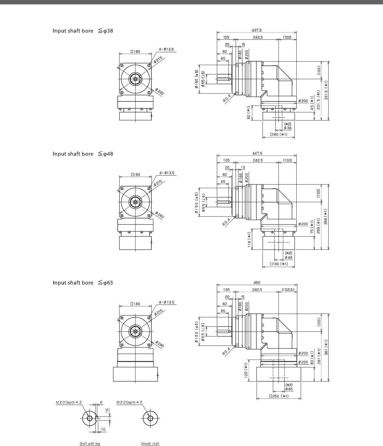
EVB-SERIES Right-angle shaft
EVB- 2-Stage Dimensions
*1) Length will vary depending on motor
*2) Bushing will be inserted to adapt to motor shaft

EVB
EVB- 3-Stage Dimensions
*1) Length will vary depending on motor
*2) Bushing will be inserted to adapt to motor shaft

EVB-SERIES Right-angle shaft
EVB- 2-Stage Adapter Dimensions
*1) Double reduction : /~ /
Model number **: Adapter code 2-Stage
L1 L2 L3 L4 L5
EVB-180-□-□-28**
(S≦ 28)
FA•FB•FC -- -- -- -- --
GA•GB•GC•GD•GE•GF•GG•GH -- -- -- -- --
HA•HC•HD -- -- -- -- --
HB -- -- -- -- --
HF -- -- -- -- --
JA•JB•JC•JF -- -- -- -- --
KA•KB•KE -- -- -- -- --
LA -- -- -- -- --
LB -- -- -- -- --
MA -- -- -- -- --
MB -- -- -- -- --
EVB-180-□-□-38**
(28 S≦ 38)
HA 331.5 231.5 □130 45 82
HB•HE 326.5 226.5 □130 40 77
JA 331.5 231.5 □150 45 82
KA•KB•KC 331.5 231.5 □180 45 82
KD 366.5 266.5 □180 80 117
KE 346.5 246.5 □180 60 97
LB 341.5 241.5 □200 55 92
MA•MB 331.5 231.5 □220 45 82
MC 346.5 246.5 □220 60 97
MD 341.5 241.5 □220 55 92
NA 331.5 231.5 □250 45 82
EVB-180-□-□-48**
(38 S≦ 48)
KA 368 268 □180 75 118
KB•KC 348 248 □180 55 98
LA 348 248 □200 55 98
MA 348 248 □220 55 98
MB 368 268 □220 75 118
NA 368 268 □250 75 118
PA 368 268 □280 75 118
EVB-180-□-□-65**
(48 S≦ 65)
MA•MB•MC•MD 381 281 □220 80 122
NA•NC 381 281 □250 80 122
NB•ND 411 311 □250 110 152
PA 401 301 □280 100 142
PB 411 311 □280 110 152
A more comprehensive adapter ange o ering can be found using the NIDECSHIMPO Online Selector Tool. The variety is constantly
expanding and being updated on the Selector Tool. If you have any questions or need any support, contact NIDECSHIMPO.
For an explanation on the Adapter Flange Code, please turn to page .
*) Bushing will be inserted to adapt to motor shaft

EVB
EVB- 3-Stage Adapter Dimensions
*1) Triple reduction : /~ /
Model number **: Adapter code 3-Stage
L1 L2 L3 L4 L5
EVB-180-□-□-28**
(S≦ 28)
FA•FB•FC 252 152 □100 35 67
GA•GB•GC•GD•GE•GF•GG•GH 252 152 □115 35 67
HA•HC•HD 252 152 □130 35 67
HB 262 162 □130 45 77
HF 247 147 □130 30 62
JA•JB•JC•JF 252 152 □150 35 67
KA•KB•KE 252 152 □180 35 67
LA 252 152 □200 35 67
LB 262 162 □200 45 77
MA 252 152 □220 35 67
MB 262 162 □220 45 77
EVB-180-□-□-38**
(28 S≦ 38)
HA 267 167 □130 45 82
HB•HE 262 162 □130 40 77
JA 267 167 □150 45 82
KA•KB•KC 267 167 □180 45 82
KD 302 202 □180 80 117
KE 282 182 □180 60 97
LB 277 177 □200 55 92
MA•MB 267 167 □220 45 82
MC 282 182 □220 60 97
MD 277 177 □220 55 92
NA 267 167 □250 45 82
EVB-180-□-□-48**
(38 S≦ 48)
KA 313 213 □180 75 118
KB•KC 293 193 □180 55 98
LA 293 193 □200 55 98
MA 293 193 □220 55 98
MB 313 213 □220 75 118
NA 313 213 □250 75 118
PA 313 213 □280 75 118
EVB-180-□-□-65**
(48 S≦ 65)
MA•MB•MC•MD -- -- -- -- --
NA•NC -- -- -- -- --
NB•ND -- -- -- -- --
PA -- -- -- -- --
PB -- -- -- -- --
A more comprehensive adapter ange o ering can be found using the NIDECSHIMPO Online Selector Tool. The variety is constantly
expanding and being updated on the Selector Tool. If you have any questions or need any support, contact NIDECSHIMPO.
For an explanation on the Adapter Flange Code, please turn to page .
*) Bushing will be inserted to adapt to motor shaft

EVB-SERIES Right-angle shaft
EVB- 2-Stage Specifications
EVB- 3-Stage Specifications
Frame Size 220
Stage 2-Stage
Ratio Units Note 3 4 5 6 7 8 9 10
Nominal Output Torque [Nm] *1 575 765 960 1150 1200 1200 800 800
Maximum Acceleration Torque [Nm] *2 1015 1355 1695 1840 1840 1760 1520 1280
Emergency Stop Torque [Nm] *3 2500 3300 4000 4500 4500 4500 3600 3600
Nominal Input Speed [rpm] *4 1000
Maximum Input Speed [rpm] *5 2000
No Load Running Torque [Nm] *6 14.5
Permitted Radial Load [N] *7 5800 6400 6900 7300 7700 8000 8400 8700
Permitted Axial Load [N] *8 6400 7200 7900 8600 9200 9700 10000 11000
Maximum Radial Load [N] *9 15000
Maximum Axial Load [N] *10 14000
Moment of Inertia (≤Ø 38) [kgcm2] -- -- -- -- -- -- -- -- --
Moment of Inertia (≤Ø 48) [kgcm2] -- 148.0 122.9 113.3 108.1 104.7 102.7 101.6 101.0
Moment of Inertia (≤ Ø 65) [kgcm2] -- 223.2 198.1 188.6 183.3 180.0 178.0 176.8 176.2
E ciency [%] *11 93
Torsional Rigidity [Nm/arcmin] *12 400
Maximum Torsional Backlash [Arc-min] -- ≤ 6
Noise Level [dB] *13 ≤ 85
Protection Class -- *14 IP54 (IP65)
Ambient Temperature [°C] -- 0-40
Permitted Housing Temperature [°C] -- 90
Weight [kg] *15 66
Frame Size 220
Stage 3-Stage
Ratio Units Note 15 16 20 25 28 30 35 40
Nominal Output Torque [Nm] *1 800 1200 1200 1200 1200 800 1200 1200
Maximum Acceleration Torque [Nm] *2 1280 1840 1840 1840 1840 1280 1840 1840
Emergency Stop Torque [Nm] *3 3600 4500 4500 4500 4500 3600 4500 4500
Nominal Input Speed [rpm] *4 1000
Maximum Input Speed [rpm] *5 2000
No Load Running Torque [Nm] *6 10.2
Permitted Radial Load [N] *7 9900 10000 11000 12000 12000 13000 13000 14000
Permitted Axial Load [N] *8 13000 13000 14000 14000 14000 14000 14000 14000
Maximum Radial Load [N] *9 15000
Maximum Axial Load [N] *10 14000
Moment of Inertia (≤Ø 38) [kgcm2] -- 36.32 37.24 35.75 35.47 36.39 34.39 35.21 34.25
Moment of Inertia (≤Ø 48) [kgcm2] -- 66.14 67.06 65.57 65.28 66.21 64.21 65.03 64.07
Moment of Inertia (≤ Ø 65) [kgcm2] -- -- -- -- -- -- -- -- --
E ciency [%] *11 88
Torsional Rigidity [Nm/arcmin] *12 400
Maximum Torsional Backlash [Arc-min] -- ≤ 9
Noise Level [dB] *13 ≤ 85
Protection Class -- *14 IP54 (IP65)
Ambient Temperature [°C] -- 0-40
Permitted Housing Temperature [°C] -- 90
Weight [kg] *15 67

EVB
EVB- 3-Stage Specifications
Frame Size 220
Stage 3-Stage
Ratio Units Note 45 50 60 70 80 90 100
Nominal Output Torque [Nm] *1 800 1200 1200 1200 1200 800 800
Maximum Acceleration Torque [Nm] *2 1040 1840 1840 1840 1440 1040 960
Emergency Stop Torque [Nm] *3 3600 4500 4500 4500 4500 3600 3600
Nominal Input Speed [rpm] *4 1000
Maximum Input Speed [rpm] *5 2000
No Load Running Torque [Nm] *6 10.2
Permitted Radial Load [N] *7 14000 15000 15000 15000 15000 15000 15000
Permitted Axial Load [N] *8 14000 14000 14000 14000 14000 14000 14000
Maximum Radial Load [N] *9 15000
Maximum Axial Load [N] *10 14000
Moment of Inertia (≤Ø 38) [kgcm2] -- 35.10 34.18 34.14 34.11 34.10 34.09 34.08
Moment of Inertia (≤Ø 48) [kgcm2] -- 64.92 63.99 63.95 63.93 63.91 63.90 63.90
Moment of Inertia (≤ Ø 65) [kgcm2] -- -- -- -- -- -- -- --
E ciency [%] *11 88
Torsional Rigidity [Nm/arcmin] *12 400
Maximum Torsional Backlash [Arc-min] -- ≤ 9
Noise Level [dB] *13 ≤ 85
Protection Class -- *14 IP54 (IP65)
Ambient Temperature [°C] -- 0-40
Permitted Housing Temperature [°C] -- 90
Weight [kg] *15 67
*1) At nominal input speed, service life is , hours
*2) The maximum torque when starting or stopping operation
*3) The maximum torque allowed under a stress situation (Permitted , times during service life)
*4) The average input speed
*5) The maximum intermittent input speed
*6) This is the torque at no load applied on the input shaft. The input speed is rpm for EVB
*7) At this load and nominal input speed, service life will be , hours. (The radial load applied to the output side bearing)
*8) At this load and nominal input speed, service life will be , hours. (The axial load applied to the output shaft center)
*9) The maximum radial load that the reducer can accept
*10) The maximum axial load that the reducer can accept
*11) The e ciency at the nominal torque rating
*12) This does not include the lost motion
*13) Contact NIDEC-SHIMPO for the testing conditions and environment
*14) IP (wash-down) is available as an option. Contact NIDECSHIMPO for more details and our food grade options
*15) The weight may vary slightly between models

EVB-SERIES Right-angle shaft
EVB- 2-Stage Dimensions
*1) Length will vary depending on motor
*2) Bushing will be inserted to adapt to motor shaft

EVB
EVB- 3-Stage Dimensions
*1) Length will vary depending on motor
*2) Bushing will be inserted to adapt to motor shaft

EVB-SERIES Right-angle shaft
EVB- 2-Stage Adapter Dimensions
*1) Double reduction : /~ /
*2) Bushing will be inserted to adapt to motor shaft
Model number **: Adapter code 2-Stage
L1 L2 L3 L4 L5
EVB-220-□-□-38**
(S≦ 38)
HA -- -- -- -- --
HB•HE -- -- -- -- --
JA -- -- -- -- --
KA•KB•KC -- -- -- -- --
KD -- -- -- -- --
KE -- -- -- -- --
LA -- -- -- -- --
LB -- -- -- -- --
MA•MB -- -- -- -- --
MC -- -- -- -- --
MD -- -- -- -- --
NA -- -- -- -- --
EVB-220-□-□-48**
(38 S≦ 48)
KA 399.5 287 □180 75 118
KB•KC 379.5 267 □180 55 98
LA 379.5 267 □200 55 98
MA 379.5 267 □220 55 98
MB 399.5 287 □220 75 118
NA 399.5 287 □250 75 118
PA 399.5 287 □280 75 118
EVB-220-□-□-65**
(48 S≦ 65)
MA•MB•MC•MD 405.5 293 □220 80 122
NA•NC 405.5 293 □250 80 122
NB•ND 435.5 323 □250 110 152
PA 425.5 313 □280 100 142
PB 435.5 323 □280 110 152
QA•QB 425.5 313 □320 100 142
A more comprehensive adapter ange o ering can be found using the NIDECSHIMPO Online Selector Tool. The variety is constantly
expanding and being updated on the Selector Tool. If you have any questions or need any support, contact NIDECSHIMPO.
For an explanation on the Adapter Flange Code, please turn to page .

EVB
EVB- 3-Stage Adapter Dimensions
*1) Triple reduction : /~ /
*2) Bushing will be inserted to adapt to motor shaft
Model number **: Adapter code 3-Stage
L1 L2 L3 L4 L5
EVB-220-□-□-38**
(S≦ 38)
HA 344 231.5 □130 45 82
HB•HE 339 226.5 □130 40 77
JA 344 231.5 □150 45 82
KA•KB•KC 344 231.5 □180 45 82
KD 379 266.5 □180 80 117
KE 359 246.5 □180 60 97
LA 344 231.5 □200 45 82
LB 354 241.5 □200 55 92
MA•MB 344 231.5 □220 45 82
MC 359 246.5 □220 60 97
MD 354 241.5 □220 55 92
NA 344 231.5 □250 45 82
EVB-220-□-□-48**
(38 S≦ 48)
KA 380.5 268 □180 75 118
KB•KC 360.5 248 □180 55 98
LA 360.5 248 □200 55 98
MA 360.5 248 □220 55 98
MB 380.5 268 □220 75 118
NA 380.5 268 □250 75 118
PA 380.5 268 □280 75 118
EVB-220-□-□-65**
(48 S≦ 65)
MA•MB•MC•MD -- -- -- -- --
NA•NC -- -- -- -- --
NB•ND -- -- -- -- --
PA -- -- -- -- --
PB -- -- -- -- --
QA•QB -- -- -- -- --
A more comprehensive adapter ange o ering can be found using the NIDECSHIMPO Online Selector Tool. The variety is constantly
expanding and being updated on the Selector Tool. If you have any questions or need any support, contact NIDECSHIMPO.
For an explanation on the Adapter Flange Code, please turn to page .

For applications that require exceptional load handling capabili-
ties in an optimum foot print, the EVS series is the performance
leader. The right-angle equivalent to the VRS, the EVS internal de-
sign provides an extremely smooth running, quiet reducer even
when challenging static forces are applied. The tapered roller bear-
ings at the output side allow the EVS to handle larger radial and
thrust load forces than the typical planetary gearbox.
The EVS series is a high precision right-angle gearhead having a maxi-
mum arc-min backlash rating, while handling a peak output torque
reaching Nm. The series is commonly utilized in custom assem-
bly applications or in robotic tooling. Very low backlash and o -set
load handling capabilities are critical characteristics for these types
of applications.
EVS-SERIES

EVS-SERIES
■Industry standard mounting dimensions
■Large variety of reduction ratios to choose from
■Thru-bolt mounting style
■Low backlash (≤ arc-min)
■Space-saving design, when minimal envelope available
■Highest radial and axial load ratings among right-angle options
■Readily available
EVS

EVS-SERIES Right-angle shaft
EVS-Series Features
1 Space–saving features; motor can be located at a degree position from the reducer providing a more
compact footprint
2 High rigidity and torque capacity are achieved by using uncaged needle roller bearings
3 High load capacity: Tapered roller bearings were added to the output section to increase radial and axial
load ratings
4 Adapter-bushing connection enable a simple, e ective attachment to most servo motors
5 No leakage through the seal; high viscosity, anti-separation grease does not liquefy and does not migrate
away from the gears
6 No need to replace the grease for the life of the unit. The reducer can be positioned in any orientation
3
2
4
5
1
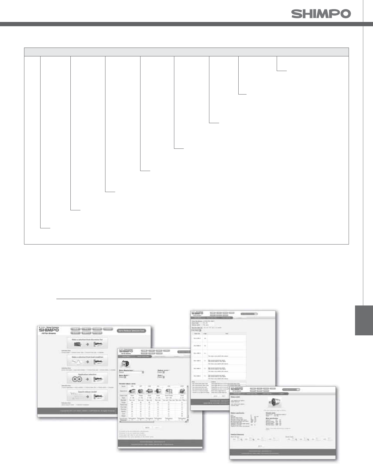
EVS
EVS-Series Model Code
Backlash
㩷Adapter ange code
EV
SB100 − −− 7 K 4 19HB16
Output style
2stage: 3, 4, 5, 6, 7, 8, 9, 10
3stage: 15, 16, 20, 25, 28, 30, 35, 40, 45, 50, 60, 70, 80, 90, 100
Ratio
K・・・ Shaft with key
S・・・ Smooth shaft
Generation of design
Frame size 060, 075, 100, 140, 180, 210, 240
Model name for ABLE reducer
Series name EVS Series
060, 075, 100, 140
4 arc-min (2stage), 7 arc-min (3stage)
180, 210, 240
6 arc-min (2stage), 9 arc-min (3stage)
*1) Adapter ange code
Adapter ange code varies depending on the motor.
Contact us for additional information or refer to our online reducer selection tool.
Selection tool www.nidec-shimpo.co.jp/selection/eng

EVS-SERIES Right-angle shaft
EVS- 2-Stage Specifications
EVS- 3-Stage Specifications
Frame Size 060
Stage 2-Stage
Ratio Unit Note 3 4 5 6 7 8 9 10
Nominal Output Torque [Nm] *1 12 16 22 24 24 24 16 16
Maximum Acceleration Torque [Nm] *2 24 32 40 45 45 45 32 32
Emergency Stop Torque [Nm] *3 50 65 80 90 90 90 65 65
Nominal Input Speed [rpm] *4 3000
Maximum Input Speed [rpm] *5 6000
No Load Running Torque [Nm] *6 0.33
Permitted Radial Load [N] *7 1700 1900 2000 2100 2200 2300 2400 2400
Permitted Axial Load [N] *8 2300 2500 2700 2700 2700 2700 2700 2700
Maximum Radial Load [N] *9 3000
Maximum Axial Load [N] *10 2700
Moment of Inertia (≤ Ø 8) [kgcm2] -- 0.320 0.271 0.251 0.242 0.235 0.232 0.229 0.228
Moment of Inertia (≤ Ø 14) [kgcm2] -- 0.395 0.346 0.326 0.317 0.310 0.307 0.304 0.303
Moment of Inertia (≤ Ø 19) [kgcm2] -- 0.584 0.535 0.516 0.506 0.500 0.496 0.494 0.492
E ciency [%] *11 93
Torsional Rigidity [Nm/arc-min] *12 3
Maximum Torsional Backlash [arc-min] -- ≤ 4
Noise Level [dB] *13 80
Protection Class -- *14 IP54 (IP65)
Ambient Temperature [°C] -- 0-40
Permitted Housing Temperature [°C] -- 90
Weight [kg] *15 2
Frame Size 060
Stage 3-Stage
Ratio Unit Note 15 16 20 25 28 30 35 40
Nominal Output Torque [Nm] *1 16 24 24 24 24 16 24 24
Maximum Acceleration Torque [Nm] *2 32 45 45 45 45 32 45 45
Emergency Stop Torque [Nm] *3 65 90 90 90 90 65 90 90
Nominal Input Speed [rpm] *4 3000
Maximum Input Speed [rpm] *5 6000
No Load Running Torque [Nm] *6 0.20
Permitted Radial Load [N] *7 2800 2800 3000 3000 3000 3000 3000 3000
Permitted Axial Load [N] *8 2700 2700 2700 2700 2700 2700 2700 2700
Maximum Radial Load [N] *9 3000
Maximum Axial Load [N] *10 2700
Moment of Inertia (≤ Ø 8) [kgcm2] -- 0.074 0.079 0.072 0.071 0.077 0.062 0.070 0.061
Moment of Inertia (≤ Ø 14) [kgcm2] -- 0.118 0.124 0.116 0.115 0.122 0.106 0.115 0.106
Moment of Inertia (≤ Ø 19) [kgcm2] -- -- -- -- -- -- -- -- --
E ciency [%] *11 88
Torsional Rigidity [Nm/arc-min] *12 3
Maximum Torsional Backlash [arc-min] -- ≤ 7
Noise Level [dB] *13 80
Protection Class -- *14 IP54 (IP65)
Ambient Temperature [°C] -- 0-40
Permitted Housing Temperature [°C] -- 90
Weight [kg] *15 1.8

EVS
EVS- 3-Stage Specifications
Frame Size 060
Stage 3-Stage
Ratio Unit Note 45 50 60 70 80 90 100
Nominal Output Torque [Nm] *1 16 24 24 24 24 16 16
Maximum Acceleration Torque [Nm] *2 32 45 45 45 45 32 32
Emergency Stop Torque [Nm] *3 65 90 90 90 90 65 65
Nominal Input Speed [rpm] *4 3000
Maximum Input Speed [rpm] *5 6000
No Load Running Torque [Nm] *6 0.20
Permitted Radial Load [N] *7 3000 3000 3000 3000 3000 3000 3000
Permitted Axial Load [N] *8 2700 2700 2700 2700 2700 2700 2700
Maximum Radial Load [N] *9 3000
Maximum Axial Load [N] *10 2700
Moment of Inertia (≤ Ø 8) [kgcm2] -- 0.070 0.061 0.061 0.061 0.061 0.061 0.061
Moment of Inertia (≤ Ø 14) [kgcm2] -- 0.115 0.106 0.106 0.106 0.105 0.105 0.105
Moment of Inertia (≤ Ø 19) [kgcm2] -- -- -- -- -- -- -- --
E ciency [%] *11 88
Torsional Rigidity [Nm/arc-min] *12 3
Maximum Torsional Backlash [arc-min] -- ≤ 7
Noise Level [dB] *13 80
Protection Class -- *14 IP54 (IP65)
Ambient Temperature [°C] -- 0-40
Permitted Housing Temperature [°C] -- 90
Weight [kg] *15 1.8
*1) At nominal input speed, service life is , hours
*2) The maximum torque when starting or stopping operation
*3) The maximum torque allowed under a stress situation (Permitted , times during service life)
*4) The average input speed
*5) The maximum intermittent input speed
*6) This is the torque at no load applied on the input shaft. The input speed is rpm for EVS
*7) At this load and nominal input speed, service life will be , hours. (The radial load applied to the output side bearing)
*8) At this load and nominal input speed, service life will be , hours. (The axial load applied to the output shaft center)
*9) The maximum radial load that the reducer can accept
*10) The maximum axial load that the reducer can accept
*11) The e ciency at the nominal torque rating
*12) This does not include the lost motion
*13) Contact NIDEC-SHIMPO for the testing conditions and environment
*14) IP (wash-down) is available as an option. Contact NIDECSHIMPO for more details and our food grade options
*15) The weight may vary slightly between models

EVS-SERIES Right-angle shaft
EVS- 2-Stage Dimensions
*1) Length will vary depending on motor
*2) Bushing will be inserted to adapt to motor shaft

EVS
EVS- 3-Stage Dimensions
*1) Length will vary depending on motor
*2) Bushing will be inserted to adapt to motor shaft

EVS-SERIES Right-angle shaft
EVS- 2-Stage Adapter Dimensions
*1) Double reduction : /~ /
*2) Bushing will be inserted to adapt to motor shaft.
Model number **: Adapter code 2-Stage
L1 L2 L3 L4 L5
EVS-060-□-□-8**
(S≦ 8)
AA•AC•AD•AF•AG•AL•AM•AN•AQ 103 71.5 □52 15.5 32
AB•AE•AH•AJ•AK 108 76.5 □52 20.5 37
BA•BB•BD•BE•BG•BH•BJ 103 71.5 □60 15.5 32
BC•BF 108 76.5 □60 20.5 37
CA 108 76.5 □70 20.5 37
EVS-060-□-□-14**
(8 S≦ 14)
BA•BB•BD•BE•BF•BG•BH•BJ•BK•BP 109 77.5 □65 16.5 35
BC•BH•BM•BN 114 82.5 □65 21.5 40
BL 119 87.5 □65 26.5 45
CA•CC 109 77.5 □70 16.5 35
CB 114 82.5 □70 21.5 40
DA•DB•DC•DD•DF•DH•DJ 109 77.5 □80 16.5 35
DE•DL 114 82.5 □80 21.5 40
DG•DK 119 87.5 □80 26.5 45
EA•EB•EC•EF•EG•EK•EL 109 77.5 □90 16.5 35
EJ•EM 114 82.5 □90 21.5 40
ED•EE•EH 119 87.5 □90 26.5 45
FA 109 77.5 □100 16.5 35
FB 119 87.5 □100 26.5 45
EVS-060-□-□-19**
(14 S≦ 19)
DA•DB•DC 126 94.5 □80 25 50
DD 136 104.5 □80 35 60
DE 131 99.5 □80 30 55
EA 131 99.5 □90 30 55
EB•ED 126 94.5 □90 25 50
EC 136 104.5 □90 35 60
FA 126 94.5 □100 25 50
FB 136 104.5 □100 35 60
A more comprehensive adapter ange o ering can be found using the NIDECSHIMPO Online Selector Tool. The variety is constantly
expanding and being updated on the Selector Tool. If you have any questions or need any support, contact NIDECSHIMPO.
For an explanation on the Adapter Flange Code, please turn to page .

EVS
EVS- 3-Stage Adapter Dimensions
*1) Triple reduction : /~ /
*2) Bushing will be inserted to adapt to motor shaft.
Model number **: Adapter code 3-Stage
L1 L2 L3 L4 L5
EVS-060-□-□-8**
(S≦ 8)
AA•AC•AD•AF•AG•AL•AM•AN•AQ 96 64.5 □52 15.5 32
AB•AE•AH•AJ•AK 101 69.5 □52 20.5 37
BA•BB•BD•BE•BG•BH•BJ 96 64.5 □60 15.5 32
BC•BF 101 69.5 □60 20.5 37
CA 101 69.5 □70 20.5 37
EVS-060-□-□-14**
(8 S≦ 14)
BA•BB•BD•BE•BF•BG•BH•BJ•BK•BP 100 68.5 □65 16.5 35
BC•BH•BM•BN 105 73.5 □65 21.5 40
BL 110 78.5 □65 26.5 45
CA•CC 100 68.5 □70 16.5 35
CB 105 73.5 □70 21.5 40
DA•DB•DC•DD•DF•DH•DJ 100 68.5 □80 16.5 35
DE•DL 105 73.5 □80 21.5 40
DG•DK 110 78.5 □80 26.5 45
EA•EB•EC•EF•EG•EK•EL 100 68.5 □90 16.5 35
EJ•EM 105 73.5 □90 21.5 40
ED•EE•EH 110 78.5 □90 26.5 45
FA 100 68.5 □100 16.5 35
FB 110 78.5 □100 26.5 45
EVS-060-□-□-19**
(14 S≦ 19)
DA•DB•DC -- -- -- -- --
DD -- -- -- -- --
DE -- -- -- -- --
EA -- -- -- -- --
EB•ED -- -- -- -- --
EC -- -- -- -- --
FA -- -- -- -- --
FB -- -- -- -- --
A more comprehensive adapter ange o ering can be found using the NIDECSHIMPO Online Selector Tool. The variety is constantly
expanding and being updated on the Selector Tool. If you have any questions or need any support, contact NIDECSHIMPO.
For an explanation on the Adapter Flange Code, please turn to page .

EVS-SERIES Right-angle shaft
EVS- 2-Stage Specifications
EVS- 3-Stage Specifications
Frame Size 075
Stage 2-Stage
Ratio Unit Note 3 4 5 6 7 8 9 10
Nominal Output Torque [Nm] *1 45 60 65 65 65 65 45 45
Maximum Acceleration Torque [Nm] *2 65 90 90 90 90 90 65 65
Emergency Stop Torque [Nm] *3 130 170 220 220 220 220 170 170
Nominal Input Speed [rpm] *4 3000
Maximum Input Speed [rpm] *5 6000
No Load Running Torque [Nm] *6 1.13
Permitted Radial Load [N] *7 2300 2500 2700 2800 3000 3100 3200 3300
Permitted Axial Load [N] *8 3400 3700 3900 3900 3900 3900 3900 3900
Maximum Radial Load [N] *9 4300
Maximum Axial Load [N] *10 3900
Moment of Inertia (≤ Ø 8) [kgcm2] -- -- -- -- -- -- -- -- --
Moment of Inertia (≤ Ø 14) [kgcm2] -- 2.070 1.870 1.780 1.740 1.720 1.700 1.690 1.690
Moment of Inertia (≤ Ø 19) [kgcm2] -- 2.400 2.200 2.110 2.070 2.050 2.030 2.020 2.020
Moment of Inertia (≤ Ø 28) [kgcm2] -- 4.530 4.320 4.240 4.200 4.170 4.160 4.150 4.150
E ciency [%] *11 93
Torsional Rigidity [Nm/arc-min] *12 10
Maximum Torsional Backlash [arc-min] -- ≤ 4
Noise Level [dB] *13 80
Protection Class -- *14 IP54 (IP65)
Ambient Temperature [°C] -- 0-40
Permitted Housing Temperature [°C] -- 90
Weight [kg] *15 4.8
Frame Size 075
Stage 3-Stage
Ratio Unit Note 15 16 20 25 28 30 35 40
Nominal Output Torque [Nm] *1 45 65 65 65 65 45 65 65
Maximum Acceleration Torque [Nm] *2 65 110 110 110 110 65 110 110
Emergency Stop Torque [Nm] *3 170 220 220 220 220 170 220 220
Nominal Input Speed [rpm] *4 3000
Maximum Input Speed [rpm] *5 6000
No Load Running Torque [Nm] *6 0.55
Permitted Radial Load [N] *7 3700 3800 4000 4300 4300 4300 4300 4300
Permitted Axial Load [N] *8 3900 3900 3900 3900 3900 3900 3900 3900
Maximum Radial Load [N] *9 4300
Maximum Axial Load [N] *10 3900
Moment of Inertia (≤ Ø 8) [kgcm2] -- 0.330 0.380 0.330 0.320 0.370 0.250 0.320 0.250
Moment of Inertia (≤ Ø 14) [kgcm2] -- 0.410 0.460 0.400 0.400 0.450 0.320 0.400 0.320
Moment of Inertia (≤ Ø 19) [kgcm2] -- 0.600 0.650 0.590 0.590 0.640 0.510 0.580 0.510
Moment of Inertia (≤ Ø 28) [kgcm2] -- -- -- -- -- -- -- -- --
E ciency [%] *11 88
Torsional Rigidity [Nm/arc-min] *12 10
Maximum Torsional Backlash [arc-min] -- ≤ 7
Noise Level [dB] *13 80
Protection Class -- *14 IP54 (IP65)
Ambient Temperature [°C] -- 0-40
Permitted Housing Temperature [°C] -- 90
Weight [kg] *15 4.1

EVS
EVS- 3-Stage Specifications
Frame Size 075
Stage 3-Stage
Ratio Unit Note 45 50 60 70 80 90 100
Nominal Output Torque [Nm] *1 45 65 65 65 65 45 45
Maximum Acceleration Torque [Nm] *2 65 110 110 110 110 65 65
Emergency Stop Torque [Nm] *3 170 220 220 220 220 170 170
Nominal Input Speed [rpm] *4 3000
Maximum Input Speed [rpm] *5 6000
No Load Running Torque [Nm] *6 0.55
Permitted Radial Load [N] *7 4300 4300 4300 4300 4300 4300 4300
Permitted Axial Load [N] *8 3900 3900 3900 3900 3900 3900 3900
Maximum Radial Load [N] *9 4300
Maximum Axial Load [N] *10 3900
Moment of Inertia (≤ Ø 8) [kgcm2] -- 0.320 0.250 0.250 0.250 0.250 0.250 0.250
Moment of Inertia (≤ Ø 14) [kgcm2] -- 0.390 0.320 0.320 0.320 0.320 0.320 0.320
Moment of Inertia (≤ Ø 19) [kgcm2] -- 0.580 0.510 0.510 0.510 0.510 0.510 0.510
Moment of Inertia (≤ Ø 28) [kgcm2] -- -- -- -- -- -- -- --
E ciency [%] *11 88
Torsional Rigidity [Nm/arc-min] *12 10
Maximum Torsional Backlash [arc-min] -- ≤ 7
Noise Level [dB] *13 80
Protection Class -- *14 IP54 (IP65)
Ambient Temperature [°C] -- 0-40
Permitted Housing Temperature [°C] -- 90
Weight [kg] *15 4.1
*1) At nominal input speed, service life is , hours
*2) The maximum torque when starting or stopping operation
*3) The maximum torque allowed under a stress situation (Permitted , times during service life)
*4) The average input speed
*5) The maximum intermittent input speed
*6) This is the torque at no load applied on the input shaft. The input speed is rpm for EVS
*7) At this load and nominal input speed, service life will be , hours. (The radial load applied to the output side bearing)
*8) At this load and nominal input speed, service life will be , hours. (The axial load applied to the output shaft center)
*9) The maximum radial load that the reducer can accept
*10) The maximum axial load that the reducer can accept
*11) The e ciency at the nominal torque rating
*12) This does not include the lost motion
*13) Contact NIDEC-SHIMPO for the testing conditions and environment
*14) IP (wash-down) is available as an option. Contact NIDECSHIMPO for more details and our food grade options
*15) The weight may vary slightly between models

EVS-SERIES Right-angle shaft
EVS- 2-Stage Dimensions
*1) Length will vary depending on motor
*2) Bushing will be inserted to adapt to motor shaft

EVS
EVS- 3-Stage Dimensions
*1) Length will vary depending on motor
*2) Bushing will be inserted to adapt to motor shaft

EVS-SERIES Right-angle shaft
EVS- 2-Stage Adapter Dimensions
䂓䂓
䂓䂓
䂓䂓
䂓䂓
*1) Double reduction : /~ /
Model number **: Adapter code 2-Stage
L1 L2 L3 L4 L5
EVS-075-□-□-8**
(S≦ 8)
AA•AC•AD•AF•AG•AL•AM•AN•AQ -- -- -- -- --
AB•AE•AH•AJ•AK -- -- -- -- --
BA•BB•BD•BE•BG•BH•BJ -- -- -- -- --
CA -- -- -- -- --
EVS-075-□-□-14**
(8 S≦ 14)
BA•BB•BD•BE•BF•BG•BH•BJ•BK•BP 137.5 92 □65 16.5 35
BC•BH•BM•BN 142.5 97 □65 21.5 40
CA•CC 137.5 92 □70 16.5 35
DA•DB•DC•DD•DF•DH•DJ 137.5 92 □80 16.5 35
EA•EB•EC•EF•EG•EK•EL 137.5 92 □90 16.5 35
FA 137.5 92 □100 16.5 35
FB 147.5 102 □100 26.5 45
JA 152.5 107 □150 31.5 50
EVS-075-□-□-19**
(14 S≦ 19)
DA•DB•DC 145.5 100 □80 25 50
EB•ED 145.5 100 □90 25 50
FA 145.5 100 □100 25 50
FB 155.5 110 □100 35 60
GA•GC•GH 150.5 105 □115 30 55
GB•GD•GJ 145.5 100 □115 25 50
GE•GF 155.5 110 □115 35 60
HA 145.5 100 □130 25 50
HB 160.5 115 □130 40 65
HC•HD•HE 150.5 105 □130 30 55
JA 155.5 110 □150 35 60
JB 160.5 115 □150 40 65
EVS-075-□-□-28**
(19 S≦ 28)
FA•FB•FC 174.5 129 □100 35 67
FD•FE 169.5 124 □100 30 62
GA•GB•GC•GD•GE•GF•GG•GH 174.5 129 □115 35 67
HA•HC•HD 174.5 129 □130 35 67
HB 184.5 139 □130 45 77
HE 189.5 144 □130 50 82
HF 169.5 124 □130 30 62
JA•JB•JC•JF 174.5 129 □150 35 67
JD 194.5 149 □150 55 87
JE 184.5 139 □150 45 77
A more comprehensive adapter ange o ering can be found using the NIDECSHIMPO Online Selector Tool. The variety is constantly
expanding and being updated on the Selector Tool. If you have any questions or need any support, contact NIDECSHIMPO.
For an explanation on the Adapter Flange Code, please turn to page .
*) Bushing will be inserted to adapt to motor shaft

EVS
EVS- 3-Stage Adapter Dimensions
䂓䂓
䂓䂓
䂓䂓
䂓䂓
*1) Triple reduction : /~ /
Model number **: Adapter code 3-Stage
L1 L2 L3 L4 L5
EVS-075-□-□-8**
(S≦ 8)
AA•AC•AD•AF•AG•AL•AM•AN•AQ 116 71.5 □52 15.5 32
AB•AE•AH•AJ•AK 121 76.5 □52 20.5 37
BA•BB•BD•BE•BG•BH•BJ 116 71.5 □60 15.5 32
CA 121 76.5 □70 20.5 37
EVS-075-□-□-14**
(8 S≦ 14)
BA•BB•BD•BE•BF•BG•BH•BJ•BK•BP 122 77.5 □65 16.5 35
BC•BH•BM•BN 127 82.5 □65 21.5 40
CA•CC 122 77.5 □70 16.5 35
DA•DB•DC•DD•DF•DH•DJ 122 77.5 □80 16.5 35
EA•EB•EC•EF•EG•EK•EL 122 77.5 □90 16.5 35
FA 122 77.5 □100 16.5 35
FB 132 87.5 □100 26.5 45
JA 137 92.5 □150 31.5 50
EVS-075-□-□-19**
(14 S≦ 19)
DA•DB•DC 139 94.5 □80 25 50
EB•ED 139 94.5 □90 25 50
FA 139 94.5 □100 25 50
FB 149 104.5 □100 35 60
GA•GC•GH 144 99.5 □115 30 55
GB•GD•GJ 139 94.5 □115 25 50
GE•GF 149 104.5 □115 35 60
HA 139 94.5 □130 25 50
HB 154 109.5 □130 40 65
HC•HD•HE 144 99.5 □130 30 55
JA 149 104.5 □150 35 60
JB 154 109.5 □150 40 65
EVS-075-□-□-28**
(19 S≦ 28)
FA•FB•FC -- -- -- -- --
FD•FE -- -- -- -- --
GA•GB•GC•GD•GE•GF•GG•GH -- -- -- -- --
HA•HC•HD -- -- -- -- --
HB -- -- -- -- --
HE -- -- -- -- --
HF -- -- -- -- --
JA•JB•JC•JF -- -- -- -- --
JD -- -- -- -- --
JE -- -- -- -- --
A more comprehensive adapter ange o ering can be found using the NIDECSHIMPO Online Selector Tool. The variety is constantly
expanding and being updated on the Selector Tool. If you have any questions or need any support, contact NIDECSHIMPO.
For an explanation on the Adapter Flange Code, please turn to page .
*) Bushing will be inserted to adapt to motor shaft

EVS-SERIES Right-angle shaft
EVS- 2-Stage Specifications
EVS- 3-Stage Specifications
Frame Size 100
Stage 2-Stage
Ratio Unit Note 3 4 5 6 7 8 9 10
Nominal Output Torque [Nm] *1 75 100 120 150 150 150 110 110
Maximum Acceleration Torque [Nm] *2 150 200 240 300 300 300 200 200
Emergency Stop Torque [Nm] *3 320 430 500 550 550 550 450 450
Nominal Input Speed [rpm] *4 3000
Maximum Input Speed [rpm] *5 6000
No Load Running Torque [Nm] *6 1.88
Permitted Radial Load [N] *7 3400 3700 4000 4200 4400 4600 4800 4900
Permitted Axial Load [N] *8 4800 5200 5600 5900 6100 6300 6300 6300
Maximum Radial Load [N] *9 7000
Maximum Axial Load [N] *10 6300
Moment of Inertia (≤ Ø 14) [kgcm2] -- -- -- -- -- -- -- -- --
Moment of Inertia (≤ Ø 19) [kgcm2] -- 6.610 5.410 4.970 4.730 4.620 4.530 4.470 4.450
Moment of Inertia (≤ Ø 28) [kgcm2] -- 8.210 7.010 6.570 6.330 6.220 6.120 6.070 6.040
Moment of Inertia (≤ Ø 38) [kgcm2] -- 15.280 14.080 13.640 13.400 13.290 13.200 13.140 13.110
E ciency [%] *11 93
Torsional Rigidity [Nm/arc-min] *12 31
Maximum Torsional Backlash [arc-min] -- ≤ 4
Noise Level [dB] *13 85
Protection Class -- *14 IP54 (IP65)
Ambient Temperature [°C] -- 0-40
Permitted Housing Temperature [°C] -- 90
Weight [kg] *15 10.5
Frame Size 100
Stage 3-Stage
Ratio Unit Note 15 16 20 25 28 30 35 40
Nominal Output Torque [Nm] *1 110 130 150 150 150 110 150 150
Maximum Acceleration Torque [Nm] *2 200 260 300 300 300 200 300 300
Emergency Stop Torque [Nm] *3 450 550 550 550 550 450 550 550
Nominal Input Speed [rpm] *4 3000
Maximum Input Speed [rpm] *5 6000
No Load Running Torque [Nm] *6 1.11
Permitted Radial Load [N] *7 5600 5700 6100 6500 6700 6900 7000 7000
Permitted Axial Load [N] *8 6300 6300 6300 6300 6300 6300 6300 6300
Maximum Radial Load [N] *9 7000
Maximum Axial Load [N] *10 6300
Moment of Inertia (≤ Ø 14) [kgcm2] -- 2.240 2.450 2.190 2.180 2.400 1.870 2.160 1.860
Moment of Inertia (≤ Ø 19) [kgcm2] -- 2.570 2.780 2.520 2.510 2.730 2.200 2.490 2.190
Moment of Inertia (≤ Ø 28) [kgcm2] -- 4.700 4.910 4.650 4.630 4.860 4.330 4.620 4.320
Moment of Inertia (≤ Ø 38) [kgcm2] -- -- -- -- -- -- -- -- --
E ciency [%] *11 88
Torsional Rigidity [Nm/arc-min] *12 31
Maximum Torsional Backlash [arc-min] -- ≤ 7
Noise Level [dB] *13 85
Protection Class -- *14 IP54 (IP65)
Ambient Temperature [°C] -- 0-40
Permitted Housing Temperature [°C] -- 90
Weight [kg] *15 10.1

EVS
EVS- 3-Stage Specifications
Frame Size 100
Stage 3-Stage
Ratio Unit Note 45 50 60 70 80 90 100
Nominal Output Torque [Nm] *1 110 150 150 150 150 110 110
Maximum Acceleration Torque [Nm] *2 200 300 300 300 300 200 200
Emergency Stop Torque [Nm] *3 450 550 550 550 550 450 450
Nominal Input Speed [rpm] *4 3000
Maximum Input Speed [rpm] *5 6000
No Load Running Torque [Nm] *6 1.11
Permitted Radial Load [N] *7 7000 7000 7000 7000 7000 7000 7000
Permitted Axial Load [N] *8 6300 6300 6300 6300 6300 6300 6300
Maximum Radial Load [N] *9 7000
Maximum Axial Load [N] *10 6300
Moment of Inertia (≤ Ø 14) [kgcm2] -- 2.150 1.860 1.850 1.850 1.850 1.850 1.850
Moment of Inertia (≤ Ø 19) [kgcm2] -- 2.480 2.190 2.180 2.180 2.180 2.180 2.180
Moment of Inertia (≤ Ø 28) [kgcm2] -- 4.610 4.310 4.310 4.310 4.310 4.310 4.310
Moment of Inertia (≤ Ø 38) [kgcm2] -- -- -- -- -- -- -- --
E ciency [%] *11 88
Torsional Rigidity [Nm/arc-min] *12 31
Maximum Torsional Backlash [arc-min] -- ≤ 7
Noise Level [dB] *13 85
Protection Class -- *14 IP54 (IP65)
Ambient Temperature [°C] -- 0-40
Permitted Housing Temperature [°C] -- 90
Weight [kg] *15 10.1
*1) At nominal input speed, service life is , hours
*2) The maximum torque when starting or stopping operation
*3) The maximum torque allowed under a stress situation (Permitted , times during service life)
*4) The average input speed
*5) The maximum intermittent input speed
*6) This is the torque at no load applied on the input shaft. The input speed is rpm for EVS
*7) At this load and nominal input speed, service life will be , hours. (The radial load applied to the output side bearing)
*8) At this load and nominal input speed, service life will be , hours. (The axial load applied to the output shaft center)
*9) The maximum radial load that the reducer can accept
*10) The maximum axial load that the reducer can accept
*11) The e ciency at the nominal torque rating
*12) This does not include the lost motion
*13) Contact NIDEC-SHIMPO for the testing conditions and environment
*14) IP (wash-down) is available as an option. Contact NIDECSHIMPO for more details and our food grade options
*15) The weight may vary slightly between models

EVS-SERIES Right-angle shaft
EVS- 2-Stage Dimensions
*1) Length will vary depending on motor
*2) Bushing will be inserted to adapt to motor shaft

EVS
EVS- 3-Stage Dimensions
*1) Length will vary depending on motor
*2) Bushing will be inserted to adapt to motor shaft

EVS-SERIES Right-angle shaft
EVS- 2-Stage Adapter Dimensions
*1) Double reduction : /~ /
Model number **: Adapter code 2-Stage
L1 L2 L3 L4 L5
EVS-100-□-□-14**
(S≦ 14)
BA•BB•BD•BE•BF•BG•BH•BJ•BK•BP -- -- -- -- --
BC•BH•BM•BN -- -- -- -- --
CA•CC ----------
DA•DB•DC•DD•DF•DH•DJ -- -- -- -- --
EA•EB•EC•EF•EG•EK•EL -- -- -- -- --
FA -- -- -- -- --
FB -- -- -- -- --
JA -- -- -- -- --
EVS-100-□-□-19**
(14 S≦ 19)
DA•DB•DC 170 110 □80 25 50
EB•ED 170 110 □90 25 50
FA 170 110 □100 25 50
FB 180 120 □100 35 60
GB•GD•GJ 170 110 □115 25 50
HA 170 110 □130 25 50
HB 185 125 □130 40 65
JA 180 120 □150 35 60
EVS-100-□-□-28**
(19 S≦ 28)
FA•FB•FC 196 136 □100 35 67
FD•FE 191 131 □100 30 62
GA•GB•GC•GD•GE•GF•GG•GH 196 136 □115 35 67
HA•HC•HD 196 136 □130 35 67
HB 206 146 □130 45 77
HE 211 151 □130 50 82
HF 191 131 □130 30 62
JA•JB•JC•JF 196 136 □150 35 67
JD 216 156 □150 55 87
JE 206 146 □150 45 77
KA•KB•KE 196 136 □180 35 67
KD 206 146 □180 45 77
EVS-100-□-□-38**
(28 S≦ 38)
HA 213 153 □130 45 82
HB•HE 208 148 □130 40 77
JA 213 153 □150 45 82
KA•KB•KC 213 153 □180 45 82
KD 248 188 □180 80 117
KE 228 168 □180 60 97
A more comprehensive adapter ange o ering can be found using the NIDECSHIMPO Online Selector Tool. The variety is constantly
expanding and being updated on the Selector Tool. If you have any questions or need any support, contact NIDECSHIMPO.
For an explanation on the Adapter Flange Code, please turn to page .
*) Bushing will be inserted to adapt to motor shaft

EVS
EVS- 3-Stage Adapter Dimensions
*1) Triple reduction : /~ /
Model number **: Adapter code 3-Stage
L1 L2 L3 L4 L5
EVS-100-□-□-14**
(S≦ 14)
BA•BB•BD•BE•BF•BG•BH•BJ•BK•BP 152 92 □65 16.5 35
BC•BH•BM•BN 157 97 □65 21.5 40
CA•CC 152 92 □70 16.5 35
DA•DB•DC•DD•DF•DH•DJ 152 92 □80 16.5 35
EA•EB•EC•EF•EG•EK•EL 152 92 □90 16.5 35
FA 152 92 □100 16.5 35
FB 162 102 □100 26.5 45
JA 167 107 □150 31.5 50
EVS-100-□-□-19**
(14 S≦ 19)
DA•DB•DC 160 100 □80 25 50
EB•ED 160 100 □90 25 50
FA 160 100 □100 25 50
FB 170 110 □100 35 60
GB•GD•GJ 160 100 □115 25 50
HA 160 100 □130 25 50
HB 175 115 □130 40 65
JA 170 110 □150 35 60
EVS-100-□-□-28**
(19 S≦ 28)
FA•FB•FC 189 129 □100 35 67
FD•FE 184 124 □100 30 62
GA•GB•GC•GD•GE•GF•GG•GH 189 129 □115 35 67
HA•HC•HD 189 129 □130 35 67
HB 199 139 □130 45 77
HE 204 144 □130 50 82
HF 184 124 □130 30 62
JA•JB•JC•JF 189 129 □150 35 67
JD 209 149 □150 55 87
JE 199 139 □150 45 77
KA•KB•KE 189 129 □180 35 67
KD 199 139 □180 45 77
EVS-100-□-□-38**
(28 S≦ 38)
HA -- -- -- -- --
HB•HE -- -- -- -- --
JA -- -- -- -- --
KA•KB•KC -- -- -- -- --
KD -- -- -- -- --
KE -- -- -- -- --
A more comprehensive adapter ange o ering can be found using the NIDECSHIMPO Online Selector Tool. The variety is constantly
expanding and being updated on the Selector Tool. If you have any questions or need any support, contact NIDECSHIMPO.
For an explanation on the Adapter Flange Code, please turn to page .
*) Bushing will be inserted to adapt to motor shaft

EVS-SERIES Right-angle shaft
EVS- 2-Stage Specifications
EVS- 3-Stage Specifications
Frame Size 140
Stage 2-Stage
Ratio Unit Note 3 4 5 6 7 8 9 10
Nominal Output Torque [Nm] *1 130 170 200 260 300 300 200 200
Maximum Acceleration Torque [Nm] *2 260 340 400 520 600 600 400 400
Emergency Stop Torque [Nm] *3 700 950 1100 1100 1100 1100 750 750
Nominal Input Speed [rpm] *4 2000
Maximum Input Speed [rpm] *5 4000
No Load Running Torque [Nm] *6 3.26
Permitted Radial Load [N] *7 6700 7400 7900 8300 8700 9100 9400 9700
Permitted Axial Load [N] *8 9000 9000 9000 9000 9000 9000 9000 9000
Maximum Radial Load [N] *9 10000
Maximum Axial Load [N] *10 9000
Moment of Inertia (≤ Ø 19) [kgcm2] -- -- -- -- -- -- -- -- --
Moment of Inertia (≤ Ø 28) [kgcm2] -- 23.010 18.490 16.850 15.970 15.550 15.210 14.750 14.640
Moment of Inertia (≤ Ø 38) [kgcm2] -- 27.380 22.860 21.220 20.340 19.920 19.580 19.120 19.020
Moment of Inertia (≤ Ø 48) [kgcm2] -- 40.610 36.090 34.450 33.570 33.150 32.810 32.250 32.250
E ciency [%] *11 93
Torsional Rigidity [Nm/arc-min] *12 60
Maximum Torsional Backlash [arc-min] -- ≤ 4
Noise Level [dB] *13 85
Protection Class -- *14 IP54 (IP65)
Ambient Temperature [°C] -- 0-40
Permitted Housing Temperature [°C] -- 90
Weight [kg] *15 20.6
Frame Size 140
Stage 3-Stage
Ratio Unit Note 15 16 20 25 28 30 35 40
Nominal Output Torque [Nm] *1 200 300 300 300 300 200 300 300
Maximum Acceleration Torque [Nm] *2 400 600 600 600 600 400 600 600
Emergency Stop Torque [Nm] *3 750 1100 1100 1100 1100 750 1100 1100
Nominal Input Speed [rpm] *4 2000
Maximum Input Speed [rpm] *5 4000
No Load Running Torque [Nm] *6 2.56
Permitted Radial Load [N] *7 10000 10000 10000 10000 10000 10000 10000 10000
Permitted Axial Load [N] *8 9000 9000 9000 9000 9000 9000 9000 9000
Maximum Radial Load [N] *9 10000
Maximum Axial Load [N] *10 9000
Moment of Inertia (≤ Ø 19) [kgcm2] -- 6.400 7.290 6.220 6.150 7.090 4.990 6.090 4.940
Moment of Inertia (≤ Ø 28) [kgcm2] -- 7.990 8.880 7.810 7.750 8.680 6.580 7.680 6.540
Moment of Inertia (≤ Ø 38) [kgcm2] -- 15.060 15.950 14.880 14.820 15.750 13.660 14.760 13.610
Moment of Inertia (≤ Ø 48) [kgcm2] -- -- -- -- -- -- -- -- --
E ciency [%] *11 88
Torsional Rigidity [Nm/arc-min] *12 60
Maximum Torsional Backlash [arc-min] -- ≤ 7
Noise Level [dB] *13 85
Protection Class -- *14 IP54 (IP65)
Ambient Temperature [°C] -- 0-40
Permitted Housing Temperature [°C] -- 90
Weight [kg] *15 20.7

EVS
EVS- 3-Stage Specifications
Frame Size 140
Stage 3-Stage
Ratio Unit Note 45 50 60 70 80 90 100
Nominal Output Torque [Nm] *1 200 300 300 300 300 200 200
Maximum Acceleration Torque [Nm] *2 400 600 600 600 600 400 400
Emergency Stop Torque [Nm] *3 750 1100 1100 1100 1100 750 750
Nominal Input Speed [rpm] *4 2000
Maximum Input Speed [rpm] *5 4000
No Load Running Torque [Nm] *6 2.56
Permitted Radial Load [N] *7 10000 10000 10000 10000 10000 10000 10000
Permitted Axial Load [N] *8 9000 9000 9000 9000 9000 9000 9000
Maximum Radial Load [N] *9 10000
Maximum Axial Load [N] *10 9000
Moment of Inertia (≤ Ø 19) [kgcm2] -- 6.070 4.930 4.920 4.910 4.910 4.910 4.910
Moment of Inertia (≤ Ø 28) [kgcm2] -- 7.660 6.520 6.510 6.510 6.500 6.500 6.500
Moment of Inertia (≤ Ø 38) [kgcm2] -- 14.730 13.590 13.590 13.580 13.580 13.570 13.570
Moment of Inertia (≤ Ø 48) [kgcm2] -- -- -- -- -- -- -- --
E ciency [%] *11 88
Torsional Rigidity [Nm/arc-min] *12 60
Maximum Torsional Backlash [arc-min] -- ≤ 7
Noise Level [dB] *13 85
Protection Class -- *14 IP54 (IP65)
Ambient Temperature [°C] -- 0-40
Permitted Housing Temperature [°C] -- 90
Weight [kg] *15 20.7
*1) At nominal input speed, service life is , hours
*2) The maximum torque when starting or stopping operation
*3) The maximum torque allowed under a stress situation (Permitted , times during service life)
*4) The average input speed
*5) The maximum intermittent input speed
*6) This is the torque at no load applied on the input shaft. The input speed is rpm for EVS
*7) At this load and nominal input speed, service life will be , hours. (The radial load applied to the output side bearing)
*8) At this load and nominal input speed, service life will be , hours. (The axial load applied to the output shaft center)
*9) The maximum radial load that the reducer can accept
*10) The maximum axial load that the reducer can accept
*11) The e ciency at the nominal torque rating
*12) This does not include the lost motion
*13) Contact NIDEC-SHIMPO for the testing conditions and environment
*14) IP (wash-down) is available as an option. Contact NIDECSHIMPO for more details and our food grade options
*15) The weight may vary slightly between models

EVS-SERIES Right-angle shaft
EVS- 2-Stage Dimensions
*1) Length will vary depending on motor
*2) Bushing will be inserted to adapt to motor shaft

EVS
EVS- 3-Stage Dimensions
*1) Length will vary depending on motor
*2) Bushing will be inserted to adapt to motor shaft
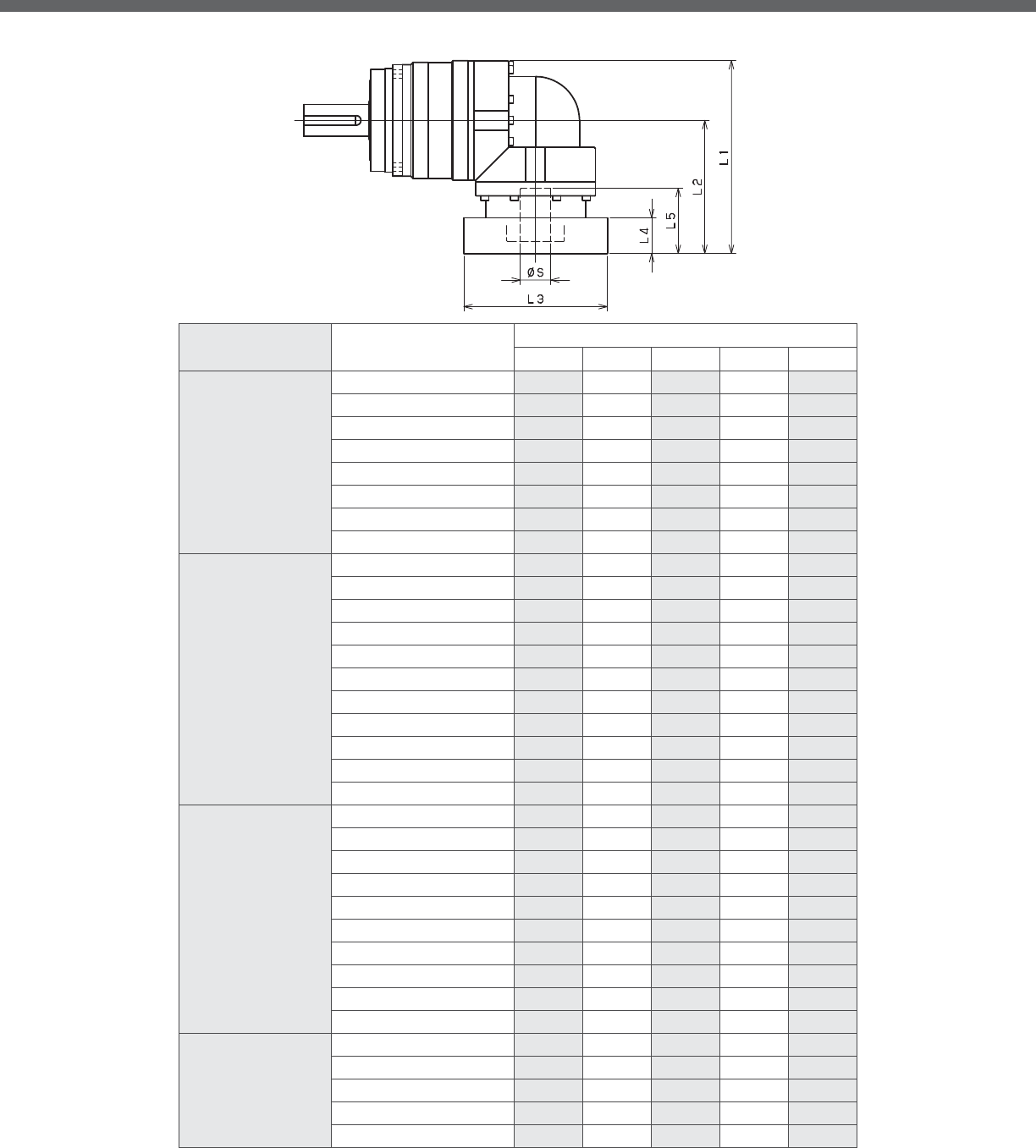
EVS-SERIES Right-angle shaft
EVS- 2-Stage Adapter Dimensions
*1) Double reduction : /~ /
Model number **: Adapter code 2-Stage
L1 L2 L3 L4 L5
EVS-140-□-□-19**
(S≦ 19)
DA•DB•DC -- -- -- -- --
EB•ED -- -- -- -- --
FA -- -- -- -- --
FB -- -- -- -- --
GB•GD•GJ -- -- -- -- --
HA -- -- -- -- --
HB -- -- -- -- --
JA -- -- -- -- --
EVS-140-□-□-28**
(19≦ S≦ 28)
FA•FB•FC 227 152 □100 35 67
GA•GB•GC•GD•GE•GF•GG•GH 227 152 □115 35 67
HA•HC•HD 227 152 □130 35 67
HB 237 162 □130 45 77
HF 222 147 □130 30 62
JA•JB•JC•JF 227 152 □150 35 67
KA•KB•KE 227 152 □180 35 67
LA 227 152 □200 35 67
LB 237 162 □200 45 77
MA 227 152 □220 35 67
MB 237 162 □220 45 77
EVS-140-□-□-38**
(28 S≦ 38)
HA 242 167 □130 45 82
HB•HE 237 162 □130 40 77
JA 242 167 □150 45 82
KA•KB•KC 242 167 □180 45 82
KD 277 202 □180 80 117
KE 257 182 □180 60 97
LB 252 177 □200 55 92
MA•MB 242 167 □220 45 82
MC 257 182 □220 60 97
MD 252 177 □220 55 92
EVS-140-□-□-48**
(38 S≦ 48)
KA 288 213 □180 75 118
KB•KC 268 193 □180 55 98
LA 268 193 □200 55 98
MA 268 193 □220 55 98
MB 288 213 □220 75 118
A more comprehensive adapter ange o ering can be found using the NIDECSHIMPO Online Selector Tool. The variety is constantly
expanding and being updated on the Selector Tool. If you have any questions or need any support, contact NIDECSHIMPO.
For an explanation on the Adapter Flange Code, please turn to page .
*) Bushing will be inserted to adapt to motor shaft

EVS
EVS- 3-Stage Adapter Dimensions
*1) Triple reduction : /~ /
Model number **: Adapter code 3-Stage
L1 L2 L3 L4 L5
EVS-140-□-□-19**
(S≦ 19)
DA•DB•DC 185 110 □80 25 50
EB•ED 185 110 □90 25 50
FA 185 110 □100 25 50
FB 195 120 □100 35 60
GB•GD•GJ 185 110 □115 25 50
HA 185 110 □130 25 50
HB 200 125 □130 40 65
JA 195 120 □150 35 60
EVS-140-□-□-28**
(19≦ S≦ 28)
FA•FB•FC 211 136 □100 35 67
GA•GB•GC•GD•GE•GF•GG•GH 211 136 □115 35 67
HA•HC•HD 211 136 □130 35 67
HB 221 146 □130 45 77
HF 206 131 □130 30 62
JA•JB•JC•JF 211 136 □150 35 67
KA•KB•KE 211 136 □180 35 67
LA 211 136 □200 35 67
LB 221 146 □200 45 77
MA 211 136 □220 35 67
MB 221 146 □220 45 77
EVS-140-□-□-38**
(28 S≦ 38)
HA 228 153 □130 45 82
HB•HE 223 148 □130 40 77
JA 228 153 □150 45 82
KA•KB•KC 228 153 □180 45 82
KD 263 188 □180 80 117
KE 243 168 □180 60 97
LB 238 163 □200 55 92
MA•MB 228 153 □220 45 82
MC 243 168 □220 60 97
MD 238 163 □220 55 92
EVS-140-□-□-48**
(38 S≦ 48)
KA -- -- -- -- --
KB•KC -- -- -- -- --
LA -- -- -- -- --
MA -- -- -- -- --
MB -- -- -- -- --
A more comprehensive adapter ange o ering can be found using the NIDECSHIMPO Online Selector Tool. The variety is constantly
expanding and being updated on the Selector Tool. If you have any questions or need any support, contact NIDECSHIMPO.
For an explanation on the Adapter Flange Code, please turn to page .
*) Bushing will be inserted to adapt to motor shaft

EVS-SERIES Right-angle shaft
EVS- 2-Stage Specifications
EVS- 3-Stage Specifications
Frame Size 180
Stage 2-Stage
Ratio Units Note 3 4 5 6 7 8 9 10
Nominal Output Torque [Nm] *1 400 575 600 600 600 600 400 400
Maximum Acceleration Torque [Nm] *2 575 770 960 1120 1120 1120 775 775
Emergency Stop Torque [Nm] *3 1300 1700 2000 2500 2500 2500 2000 2000
Nominal Input Speed [rpm] *4 1500
Maximum Input Speed [rpm] *5 3000
No Load Running Torque [Nm] *6 10.8
Permitted Radial Load [N] *7 12000 13000 14000 15000 16000 17000 17000 18000
Permitted Axial Load [N] *8 16000 17000 17000 17000 17000 17000 17000 17000
Maximum Radial Load [N] *9 19000
Maximum Axial Load [N] *10 17000
Moment of Inertia (≤Ø 28) [kgcm2] -- -- -- -- -- -- -- -- --
Moment of Inertia (≤Ø 38) [kgcm2] -- 92.00 76.72 71.23 68.28 66.08 65.00 64.38 64.10
Moment of Inertia (≤Ø 48) [kgcm2] -- 126.9 111.6 106.1 103.1 100.9 99.86 99.25 98.97
Moment of Inertia (≤ Ø 65) [kgcm2] -- 212.5 197.2 191.7 188.7 186.6 185.5 184.9 184.6
E ciency [%] *11 93
Torsional Rigidity [Nm/arcmin] *12 175
Maximum Torsional Backlash [Arc-min] -- ≤ 6
Noise Level [dB] *13 ≤ 85
Protection Class -- *14 IP54 (IP65)
Ambient Temperature [°C] -- 0-40
Permitted Housing Temperature [°C] -- 90
Weight [kg] *15 52
Frame Size 180
Stage 3-Stage
Ratio Units Note 15 16 20 25 28 30 35 40
Nominal Output Torque [Nm] *1 400 555 600 600 600 400 600 600
Maximum Acceleration Torque [Nm] *2 775 1120 1120 1120 1120 775 1120 1120
Emergency Stop Torque [Nm] *3 2000 2500 2500 2500 2500 2000 2500 2500
Nominal Input Speed [rpm] *4 1500
Maximum Input Speed [rpm] *5 3000
No Load Running Torque [Nm] *6 4.7
Permitted Radial Load [N] *7 19000 19000 19000 19000 19000 19000 19000 19000
Permitted Axial Load [N] *8 17000 17000 17000 17000 17000 17000 17000 17000
Maximum Radial Load [N] *9 19000
Maximum Axial Load [N] *10 17000
Moment of Inertia (≤Ø 28) [kgcm2] -- 11.42 12.03 11.11 10.96 11.57 10.31 10.82 10.23
Moment of Inertia (≤Ø 38) [kgcm2] -- 20.21 20.82 19.90 19.74 20.36 19.10 19.60 19.02
Moment of Inertia (≤Ø 48) [kgcm2] -- 25.03 25.64 24.72 24.56 25.18 23.92 24.42 23.84
Moment of Inertia (≤ Ø 65) [kgcm2] -- -- -- -- -- -- -- -- --
E ciency [%] *11 88
Torsional Rigidity [Nm/arcmin] *12 175
Maximum Torsional Backlash [Arc-min] -- ≤ 9
Noise Level [dB] *13 ≤ 85
Protection Class -- *14 IP54 (IP65)
Ambient Temperature [°C] -- 0-40
Permitted Housing Temperature [°C] -- 90
Weight [kg] *15 39

EVS
EVS- 3-Stage Specifications
Frame Size 180
Stage 3-Stage
Ratio Units Note 45 50 60 70 80 90 100
Nominal Output Torque [Nm] *1 400 600 600 600 600 400 400
Maximum Acceleration Torque [Nm] *2 775 1120 1120 1120 1120 775 775
Emergency Stop Torque [Nm] *3 2000 2500 2500 2500 2500 2000 2000
Nominal Input Speed [rpm] *4 1500
Maximum Input Speed [rpm] *5 3000
No Load Running Torque [Nm] *6 4.7
Permitted Radial Load [N] *7 19000 19000 19000 19000 19000 19000 19000
Permitted Axial Load [N] *8 17000 17000 17000 17000 17000 17000 17000
Maximum Radial Load [N] *9 19000
Maximum Axial Load [N] *10 17000
Moment of Inertia (≤Ø 28) [kgcm2] -- 10.76 10.19 10.17 10.16 10.15 10.14 10.14
Moment of Inertia (≤Ø 38) [kgcm2] -- 19.54 18.98 18.96 18.94 18.94 18.93 18.93
Moment of Inertia (≤Ø 48) [kgcm2] -- 24.36 23.80 23.78 23.77 23.76 23.75 23.75
Moment of Inertia (≤ Ø 65) [kgcm2] -- -- -- -- -- -- -- --
E ciency [%] *11 88
Torsional Rigidity [Nm/arcmin] *12 175
Maximum Torsional Backlash [Arc-min] -- ≤ 9
Noise Level [dB] *13 ≤ 85
Protection Class -- *14 IP54 (IP65)
Ambient Temperature [°C] -- 0-40
Permitted Housing Temperature [°C] -- 90
Weight [kg] *15 39
*1) At nominal input speed, service life is , hours
*2) The maximum torque when starting or stopping operation
*3) The maximum torque allowed under a stress situation (Permitted , times during service life)
*4) The average input speed
*5) The maximum intermittent input speed
*6) This is the torque at no load applied on the input shaft. The input speed is rpm for EVS
*7) At this load and nominal input speed, service life will be , hours. (The radial load applied to the output side bearing)
*8) At this load and nominal input speed, service life will be , hours. (The axial load applied to the output shaft center)
*9) The maximum radial load that the reducer can accept
*10) The maximum axial load that the reducer can accept
*11) The e ciency at the nominal torque rating
*12) This does not include the lost motion
*13) Contact NIDEC-SHIMPO for the testing conditions and environment
*14) IP (wash-down) is available as an option. Contact NIDECSHIMPO for more details and our food grade options
*15) The weight may vary slightly between models

EVS-SERIES Right-angle shaft
EVS- 2-Stage Dimensions
*1) Length will vary depending on motor
*2) Bushing will be inserted to adapt to motor shaft

EVS
EVS- 3-Stage Dimensions
*1) Length will vary depending on motor
*2) Bushing will be inserted to adapt to motor shaft
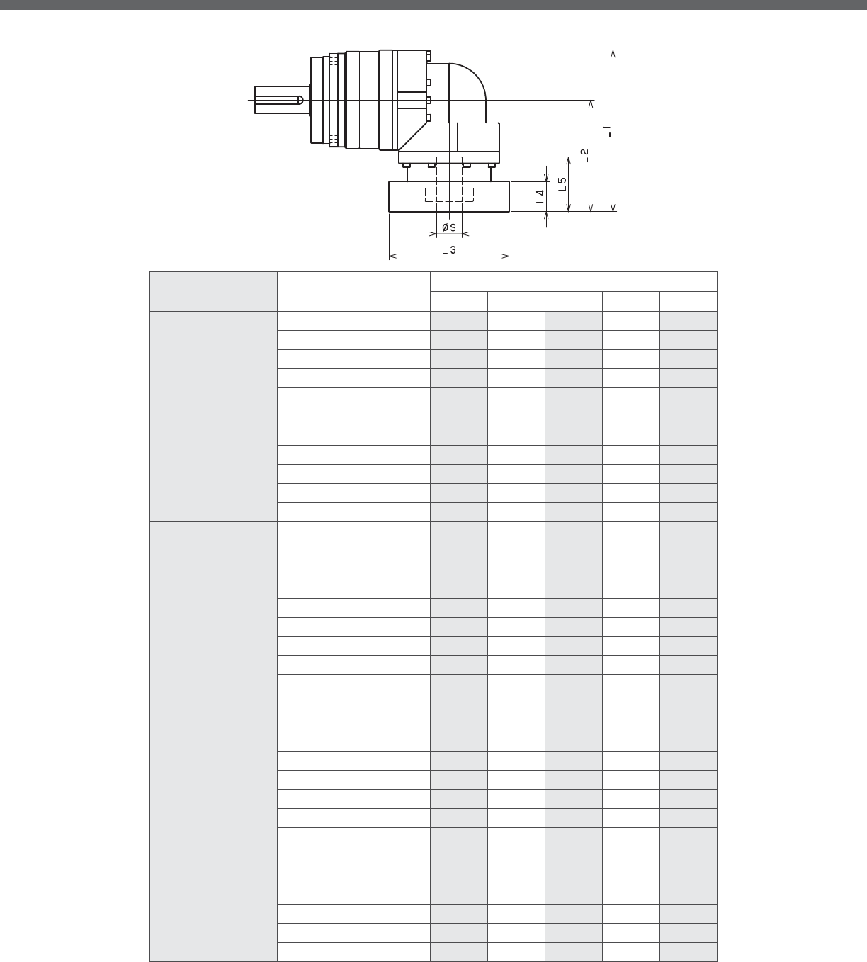
EVS-SERIES Right-angle shaft
EVS- 2-Stage Adapter Dimensions
*1) Double reduction : /~ /
Model number **: Adapter code 2-Stage
L1 L2 L3 L4 L5
EVS-180-□-□-28**
(S≦ 28)
FA•FB•FC -- -- -- -- --
GA•GB•GC•GD•GE•GF•GG•GH -- -- -- -- --
HA•HC•HD -- -- -- -- --
HB -- -- -- -- --
HF -- -- -- -- --
JA•JB•JC•JF -- -- -- -- --
KA•KB•KE -- -- -- -- --
LA -- -- -- -- --
LB -- -- -- -- --
MA -- -- -- -- --
MB -- -- -- -- --
EVS-180-□-□-38**
(28 S≦ 38)
HA 331.5 231.5 □130 45 82
HB•HE 326.5 226.5 □130 40 77
JA 331.5 231.5 □150 45 82
KA•KB•KC 331.5 231.5 □180 45 82
KD 366.5 266.5 □180 80 117
KE 346.5 246.5 □180 60 97
LB 341.5 241.5 □200 55 92
MA•MB 331.5 231.5 □220 45 82
MC 346.5 246.5 □220 60 97
MD 341.5 241.5 □220 55 92
NA 331.5 231.5 □250 45 82
EVS-180-□-□-48**
(38 S≦ 48)
KA 368 268 □180 75 118
KB•KC 348 248 □180 55 98
LA 348 248 □200 55 98
MA 348 248 □220 55 98
MB 368 268 □220 75 118
NA 368 268 □250 75 118
PA 368 268 □280 75 118
EVS-180-□-□-65**
(48 S≦ 65)
MA•MB•MC•MD 381 281 □220 80 122
NA•NC 381 281 □250 80 122
NB•ND 411 311 □250 110 152
PA 401 301 □280 100 142
PB 411 311 □280 110 152
A more comprehensive adapter ange o ering can be found using the NIDECSHIMPO Online Selector Tool. The variety is constantly
expanding and being updated on the Selector Tool. If you have any questions or need any support, contact NIDECSHIMPO.
For an explanation on the Adapter Flange Code, please turn to page .
*) Bushing will be inserted to adapt to motor shaft
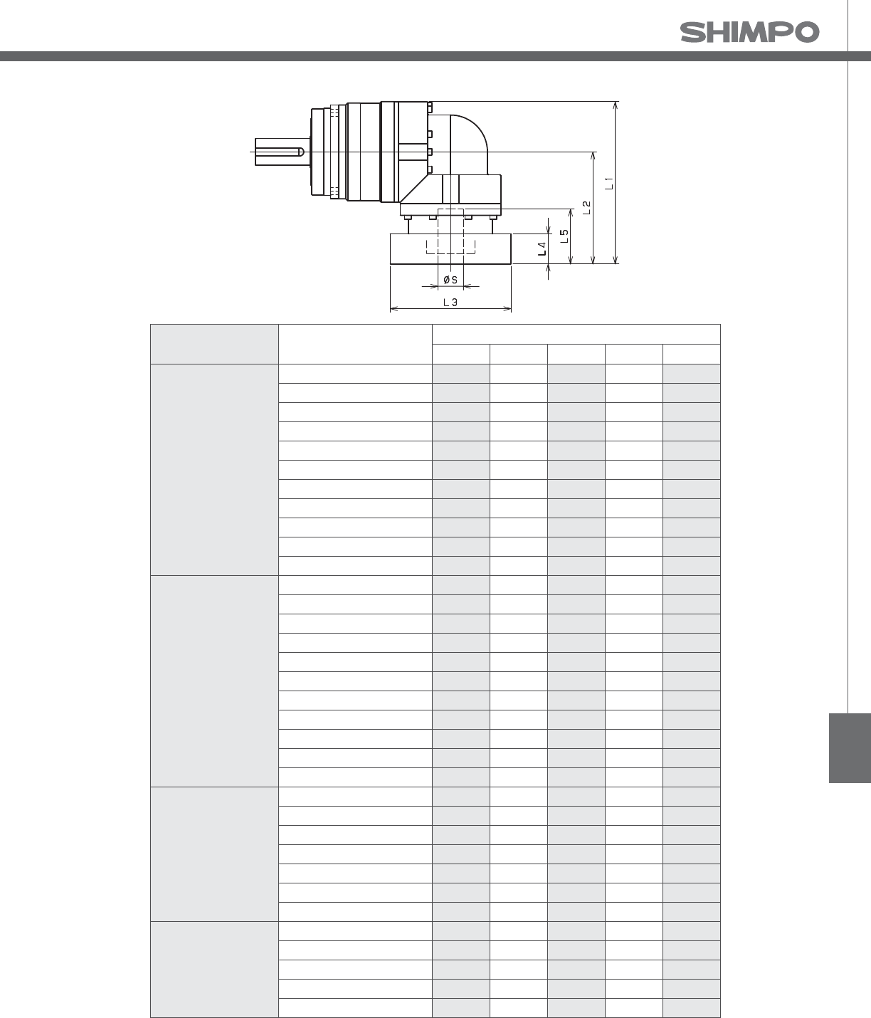
EVS
EVS- 3-Stage Adapter Dimensions
*1) Triple reduction : /~ /
Model number **: Adapter code 3-Stage
L1 L2 L3 L4 L5
EVS-180-□-□-28**
(S≦ 28)
FA•FB•FC 252 152 □100 35 67
GA•GB•GC•GD•GE•GF•GG•GH 252 152 □115 35 67
HA•HC•HD 252 152 □130 35 67
HB 262 162 □130 45 77
HF 247 147 □130 30 62
JA•JB•JC•JF 252 152 □150 35 67
KA•KB•KE 252 152 □180 35 67
LA 252 152 □200 35 67
LB 262 162 □200 45 77
MA 252 152 □220 35 67
MB 262 162 □220 45 77
EVS-180-□-□-38**
(28 S≦ 38)
HA 267 167 □130 45 82
HB•HE 262 162 □130 40 77
JA 267 167 □150 45 82
KA•KB•KC 267 167 □180 45 82
KD 302 202 □180 80 117
KE 282 182 □180 60 97
LB 277 177 □200 55 92
MA•MB 267 167 □220 45 82
MC 282 182 □220 60 97
MD 277 177 □220 55 92
NA 267 167 □250 45 82
EVS-180-□-□-48**
(38 S≦ 48)
KA 313 213 □180 75 118
KB•KC 293 193 □180 55 98
LA 293 193 □200 55 98
MA 293 193 □220 55 98
MB 313 213 □220 75 118
NA 313 213 □250 75 118
PA 313 213 □280 75 118
EVS-180-□-□-65**
(48 S≦ 65)
MA•MB•MC•MD -- -- -- -- --
NA•NC -- -- -- -- --
NB•ND -- -- -- -- --
PA -- -- -- -- --
PB -- -- -- -- --
A more comprehensive adapter ange o ering can be found using the NIDECSHIMPO Online Selector Tool. The variety is constantly
expanding and being updated on the Selector Tool. If you have any questions or need any support, contact NIDECSHIMPO.
For an explanation on the Adapter Flange Code, please turn to page .
*) Bushing will be inserted to adapt to motor shaft

EVS-SERIES Right-angle shaft
EVS- 2-Stage Specifications
EVS- 3-Stage Specifications
Frame Size 210
Stage 2-Stage
Ratio Units Note 3 4 5 6 7 8 9 10
Nominal Output Torque [Nm] *1 575 765 960 1150 1200 1200 800 800
Maximum Acceleration Torque [Nm] *2 1015 1355 1695 1840 1840 1760 1520 1280
Emergency Stop Torque [Nm] *3 2500 3300 4000 4500 4500 4500 3600 3600
Nominal Input Speed [rpm] *4 1000
Maximum Input Speed [rpm] *5 2000
No Load Running Torque [Nm] *6 14.5
Permitted Radial Load [N] *7 17000 18000 20000 21000 22000 23000 24000 24000
Permitted Axial Load [N] *8 22000 22000 22000 22000 22000 22000 22000 22000
Maximum Radial Load [N] *9 24000
Maximum Axial Load [N] *10 22000
Moment of Inertia (≤Ø 38) [kgcm2] -- -- -- -- -- -- -- -- --
Moment of Inertia (≤Ø 48) [kgcm2] -- 149.7 123.8 113.9 108.5 105.0 103.0 101.7 101.1
Moment of Inertia (≤ Ø 65) [kgcm2] -- 224.9 199.0 189.1 183.7 180.3 178.2 176.9 176.3
E ciency [%] *11 93
Torsional Rigidity [Nm/arcmin] *12 400
Maximum Torsional Backlash [Arc-min] -- ≤ 6
Noise Level [dB] *13 ≤ 85
Protection Class -- *14 IP54 (IP65)
Ambient Temperature [°C] -- 0-40
Permitted Housing Temperature [°C] -- 90
Weight [kg] *15 71
Frame Size 210
Stage 3-Stage
Ratio Units Note 15 16 20 25 28 30 35 40
Nominal Output Torque [Nm] *1 800 1200 1200 1200 1200 800 1200 1200
Maximum Acceleration Torque [Nm] *2 1280 1840 1840 1840 1840 1280 1840 1840
Emergency Stop Torque [Nm] *3 3600 4500 4500 4500 4500 3600 4500 4500
Nominal Input Speed [rpm] *4 1000
Maximum Input Speed [rpm] *5 2000
No Load Running Torque [Nm] *6 10.2
Permitted Radial Load [N] *7 24000 24000 24000 24000 24000 24000 24000 24000
Permitted Axial Load [N] *8 22000 22000 22000 22000 22000 22000 22000 22000
Maximum Radial Load [N] *9 24000
Maximum Axial Load [N] *10 22000
Moment of Inertia (≤Ø 38) [kgcm2] -- 36.39 37.30 35.79 35.49 36.41 34.41 35.22 34.26
Moment of Inertia (≤Ø 48) [kgcm2] -- 66.21 67.12 65.61 65.31 66.23 64.23 65.04 64.08
Moment of Inertia (≤ Ø 65) [kgcm2] -- -- -- -- -- -- -- -- --
E ciency [%] *11 88
Torsional Rigidity [Nm/arcmin] *12 400
Maximum Torsional Backlash [Arc-min] -- ≤ 9
Noise Level [dB] *13 ≤ 85
Protection Class -- *14 IP54 (IP65)
Ambient Temperature [°C] -- 0-40
Permitted Housing Temperature [°C] -- 90
Weight [kg] *15 73

EVS
EVS- 3-Stage Specifications
Frame Size 210
Stage 3-Stage
Ratio Units Note 45 50 60 70 80 90 100
Nominal Output Torque [Nm] *1 800 1200 1200 1200 1200 800 800
Maximum Acceleration Torque [Nm] *2 1040 1840 1840 1840 1440 1040 960
Emergency Stop Torque [Nm] *3 3600 4500 4500 4500 4500 3600 3600
Nominal Input Speed [rpm] *4 1000
Maximum Input Speed [rpm] *5 2000
No Load Running Torque [Nm] *6 10.2
Permitted Radial Load [N] *7 24000 24000 24000 24000 24000 24000 24000
Permitted Axial Load [N] *8 22000 22000 22000 22000 22000 22000 22000
Maximum Radial Load [N] *9 24000
Maximum Axial Load [N] *10 22000
Moment of Inertia (≤Ø 38) [kgcm2] -- 35.11 34.18 34.14 34.12 34.10 34.09 34.08
Moment of Inertia (≤Ø 48) [kgcm2] -- 64.92 64.00 63.96 63.93 63.92 63.90 63.90
Moment of Inertia (≤ Ø 65) [kgcm2] -- -- -- -- -- -- -- --
E ciency [%] *11 88
Torsional Rigidity [Nm/arcmin] *12 400
Maximum Torsional Backlash [Arc-min] -- ≤ 9
Noise Level [dB] *13 ≤ 85
Protection Class -- *14 IP54 (IP65)
Ambient Temperature [°C] -- 0-40
Permitted Housing Temperature [°C] -- 90
Weight [kg] *15 73
*1) At nominal input speed, service life is , hours
*2) The maximum torque when starting or stopping operation
*3) The maximum torque allowed under a stress situation (Permitted , times during service life)
*4) The average input speed
*5) The maximum intermittent input speed
*6) This is the torque at no load applied on the input shaft. The input speed is rpm for EVS
*7) At this load and nominal input speed, service life will be , hours. (The radial load applied to the output side bearing)
*8) At this load and nominal input speed, service life will be , hours. (The axial load applied to the output shaft center)
*9) The maximum radial load that the reducer can accept
*10) The maximum axial load that the reducer can accept
*11) The e ciency at the nominal torque rating
*12) This does not include the lost motion
*13) Contact NIDEC-SHIMPO for the testing conditions and environment
*14) IP (wash-down) is available as an option. Contact NIDECSHIMPO for more details and our food grade options
*15) The weight may vary slightly between models

EVS-SERIES Right-angle shaft
EVS- 2-Stage Dimensions
*1) Length will vary depending on motor
*2) Bushing will be inserted to adapt to motor shaft

EVS
EVS- 3-Stage Dimensions
*1) Length will vary depending on motor
*2) Bushing will be inserted to adapt to motor shaft

EVS-SERIES Right-angle shaft
EVS- 2-Stage Adapter Dimensions
*1) Double reduction : /~ /
*2) Bushing will be inserted to adapt to motor shaft
Model number **: Adapter code 2-Stage
L1 L2 L3 L4 L5
EVS-210-□-□-38**
(S≦ 38)
HA -- -- -- -- --
HB•HE -- -- -- -- --
JA -- -- -- -- --
KA•KB•KC -- -- -- -- --
KD -- -- -- -- --
KE -- -- -- -- --
LA -- -- -- -- --
LB -- -- -- -- --
MA•MB -- -- -- -- --
MC -- -- -- -- --
MD -- -- -- -- --
NA -- -- -- -- --
EVS-210-□-□-48**
(38 S≦48)
KA 399.5 287 □180 75 118
KB•KC 379.5 267 □180 55 98
LA 379.5 267 □200 55 98
MA 379.5 267 □220 55 98
MB 399.5 287 □220 75 118
NA 399.5 287 □250 75 118
PA 399.5 287 □280 75 118
EVS-210-□-□-65**
(48 S≦ 65)
MA•MB•MC•MD 405.5 293 □220 80 122
NA•NC 405.5 293 □250 80 122
NB•ND 435.5 323 □250 110 152
PA 425.5 313 □280 100 142
PB 435.5 323 □280 110 152
QA•QB 425.5 313 □320 100 142
A more comprehensive adapter ange o ering can be found using the NIDECSHIMPO Online Selector Tool. The variety is constantly
expanding and being updated on the Selector Tool. If you have any questions or need any support, contact NIDECSHIMPO.
For an explanation on the Adapter Flange Code, please turn to page .

EVS
EVS- 3-Stage Adapter Dimensions
*1) Triple reduction : /~ /
*2) Bushing will be inserted to adapt to motor shaft
Model number **: Adapter code 3-Stage
L1 L2 L3 L4 L5
EVS-210-□-□-38**
(S≦ 38)
HA 344 231.5 □130 45 82
HB•HE 339 226.5 □130 40 77
JA 344 231.5 □150 45 82
KA•KB•KC 344 231.5 □180 45 82
KD 379 266.5 □180 80 117
KE 359 246.5 □180 60 97
LA 344 231.5 □200 45 82
LB 354 241.5 □200 55 92
MA•MB 344 231.5 □220 45 82
MC 359 246.5 □220 60 97
MD 354 241.5 □220 55 92
NA 344 231.5 □250 45 82
EVS-210-□-□-48**
(38 S≦48)
KA 380.5 268 □180 75 118
KB•KC 360.5 248 □180 55 98
LA 360.5 248 □200 55 98
MA 360.5 248 □220 55 98
MB 380.5 268 □220 75 118
NA 380.5 268 □250 75 118
PA 380.5 268 □280 75 118
EVS-210-□-□-65**
(48 S≦ 65)
MA•MB•MC•MD -- -- -- -- --
NA•NC -- -- -- -- --
NB•ND -- -- -- -- --
PA -- -- -- -- --
PB -- -- -- -- --
QA•QB -- -- -- -- --
A more comprehensive adapter ange o ering can be found using the NIDECSHIMPO Online Selector Tool. The variety is constantly
expanding and being updated on the Selector Tool. If you have any questions or need any support, contact NIDECSHIMPO.
For an explanation on the Adapter Flange Code, please turn to page .

EVS-SERIES Right-angle shaft
EVS- 2-Stage Specifications
EVS- 3-Stage Specifications
Frame Size 240
Stage 2-Stage
Ratio Units Note 3 4 5 6 7 8 9 10
Nominal Output Torque [Nm] *1 1005 1340 1680 1920 1920 1920 1280 1280
Maximum Acceleration Torque [Nm] *2 2000 2960 2960 2960 2960 2880 2400 2080
Emergency Stop Torque [Nm] *3 4000 5400 6500 7200 7200 7200 5400 5400
Nominal Input Speed [rpm] *4 1000
Maximum Input Speed [rpm] *5 2000
No Load Running Torque [Nm] *6 25.3
Permitted Radial Load [N] *7 21000 22000 24000 25000 26000 28000 29000 29000
Permitted Axial Load [N] *8 27000 27000 27000 27000 27000 27000 27000 27000
Maximum Radial Load [N] *9 30000
Maximum Axial Load [N] *10 27000
Moment of Inertia (≤Ø 48) [kgcm2] -- -- -- -- -- -- -- -- --
Moment of Inertia (≤ Ø 65) [kgcm2] -- 217.5 156.7 134.5 122.4 112.9 108.3 105.5 104.0
E ciency [%] *11 93
Torsional Rigidity [Nm/arcmin] *12 550
Maximum Torsional Backlash [Arc-min] -- ≤ 6
Noise Level [dB] *13 ≤ 85
Protection Class -- *14 IP54 (IP65)
Ambient Temperature [°C] -- 0-40
Permitted Housing Temperature [°C] -- 90
Weight [kg] *15 122
Frame Size 240
Stage 3-Stage
Ratio Units Note 15 16 20 25 28 30 35 40
Nominal Output Torque [Nm] *1 1280 1920 1920 1920 1920 1280 1920 1920
Maximum Acceleration Torque [Nm] *2 2000 2960 2960 2960 2960 2000 2960 2960
Emergency Stop Torque [Nm] *3 5400 7200 7200 7200 7200 5400 7200 7200
Nominal Input Speed [rpm] *4 1000
Maximum Input Speed [rpm] *5 2000
No Load Running Torque [Nm] *6 16.4
Permitted Radial Load [N] *7 30000 30000 30000 30000 30000 30000 30000 30000
Permitted Axial Load [N] *8 27000 27000 27000 27000 27000 27000 27000 27000
Maximum Radial Load [N] *9 30000
Maximum Axial Load [N] *10 27000
Moment of Inertia (≤Ø 48) [kgcm2] -- 40.47 42.59 39.21 38.59 40.73 35.09 38.02 34.78
Moment of Inertia (≤ Ø 65) [kgcm2] -- -- -- -- -- -- -- -- --
E ciency [%] *11 88
Torsional Rigidity [Nm/arcmin] *12 550
Maximum Torsional Backlash [Arc-min] -- ≤ 9
Noise Level [dB] *13 ≤ 85
Protection Class -- *14 IP54 (IP65)
Ambient Temperature [°C] -- 0-40
Permitted Housing Temperature [°C] -- 90
Weight [kg] *15 113

EVS
EVS- 3-Stage Specifications
Frame Size 240
Stage 3-Stage
Ratio Units Note 45 50 60 70 80 90 100
Nominal Output Torque [Nm] *1 1280 1920 1920 1920 1920 1280 1280
Maximum Acceleration Torque [Nm] *2 1680 2960 2960 2960 2160 1680 1440
Emergency Stop Torque [Nm] *3 5400 7200 7200 7200 7200 5400 5400
Nominal Input Speed [rpm] *4 1000
Maximum Input Speed [rpm] *5 2000
No Load Running Torque [Nm] *6 16.4
Permitted Radial Load [N] *7 30000 30000 30000 30000 30000 30000 30000
Permitted Axial Load [N] *8 27000 27000 27000 27000 27000 27000 27000
Maximum Radial Load [N] *9 30000
Maximum Axial Load [N] *10 27000
Moment of Inertia (≤Ø 48) [kgcm2] -- 37.78 34.62 34.53 34.48 34.45 34.42 34.41
Moment of Inertia (≤ Ø 65) [kgcm2] -- -- -- -- -- -- -- --
E ciency [%] *11 88
Torsional Rigidity [Nm/arcmin] *12 550
Maximum Torsional Backlash [Arc-min] -- ≤ 9
Noise Level [dB] *13 ≤ 85
Protection Class -- *14 IP54 (IP65)
Ambient Temperature [°C] -- 0-40
Permitted Housing Temperature [°C] -- 90
Weight [kg] *15 113
*1) At nominal input speed, service life is , hours
*2) The maximum torque when starting or stopping operation
*3) The maximum torque allowed under a stress situation (Permitted , times during service life)
*4) The average input speed
*5) The maximum intermittent input speed
*6) This is the torque at no load applied on the input shaft. The input speed is rpm for EVS
*7) At this load and nominal input speed, service life will be , hours. (The radial load applied to the output side bearing)
*8) At this load and nominal input speed, service life will be , hours. (The axial load applied to the output shaft center)
*9) The maximum radial load that the reducer can accept
*10) The maximum axial load that the reducer can accept
*11) The e ciency at the nominal torque rating
*12) This does not include the lost motion
*13) Contact NIDEC-SHIMPO for the testing conditions and environment
*14) IP (wash-down) is available as an option. Contact NIDECSHIMPO for more details and our food grade options
*15) The weight may vary slightly between models

EVS-SERIES Right-angle shaft
EVS- 2-Stage Dimensions
*1) Length will vary depending on motor
*2) Bushing will be inserted to adapt to motor shaft

EVS
EVS- 3-Stage Dimensions
*1) Length will vary depending on motor
*2) Bushing will be inserted to adapt to motor shaft
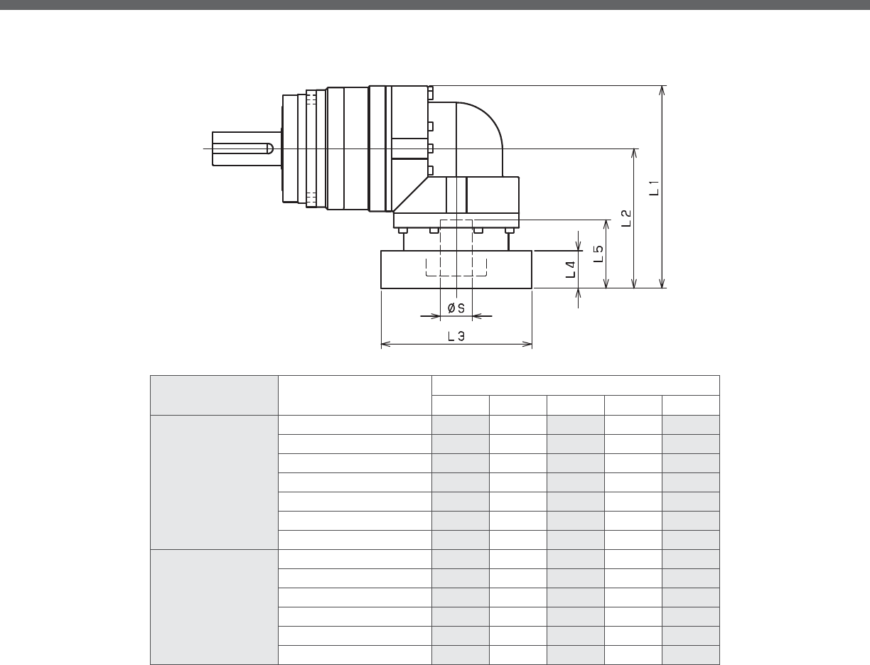
EVS-SERIES Right-angle shaft
*1) Double reduction : /~ /
*2) Bushing will be inserted to adapt to motor shaft
EVS- 2-Stage Adapter Dimensions
Model number **: Adapter code 2-Stage
L1 L2 L3 L4 L5
EVS-240-□-□-48**
(S≦ 48)
KA -- -- -- -- --
KB•KC -- -- -- -- --
LA -- -- -- -- --
MA -- -- -- -- --
MB -- -- -- -- --
NA -- -- -- -- --
PA -- -- -- -- --
EVS-240-□-□-65**
(48 S≦ 65)
MA•MB•MC•MD 447.5 321 □220 80 122
NA•NC 447.5 321 □250 80 122
NB•ND 477.5 351 □250 110 152
PA 467.5 341 □280 100 142
PB 477.5 351 □280 110 152
QA•QB 467.5 341 □320 100 142
A more comprehensive adapter ange o ering can be found using the NIDECSHIMPO Online Selector Tool. The variety is constantly
expanding and being updated on the Selector Tool. If you have any questions or need any support, contact NIDECSHIMPO.
For an explanation on the Adapter Flange Code, please turn to page .

EVS
*1) Triple reduction : /~ /
*2) Bushing will be inserted to adapt to motor shaft
EVS- 3-Stage Adapter Dimensions
Model number **: Adapter code 3-Stage
L1 L2 L3 L4 L5
EVS-240-□-□-48**
(S≦ 48)
KA 413.5 287 □180 75 118
KB•KC 393.5 267 □180 55 98
LA 393.5 267 □200 55 98
MA 393.5 267 □220 55 98
MB 413.5 287 □220 75 118
NA 413.5 287 □250 75 118
PA 413.5 287 □280 75 118
EVS-240-□-□-65**
(48 S≦ 65)
MA•MB•MC•MD -- -- -- -- --
NA•NC -- -- -- -- --
NB•ND -- -- -- -- --
PA -- -- -- -- --
PB -- -- -- -- --
QA•QB -- -- -- -- --
A more comprehensive adapter ange o ering can be found using the NIDECSHIMPO Online Selector Tool. The variety is constantly
expanding and being updated on the Selector Tool. If you have any questions or need any support, contact NIDECSHIMPO.
For an explanation on the Adapter Flange Code, please turn to page .

The STH is a mid-range speed and torque gear reducer that
sets a new standard for rotary positioning performance at
an exceptional price point. A SHIMPO ABLE planetary gearbox
is the interface between the servo motor and STH rotary stage.
The ABLE reducer features simple mounting of nearly any small
to medium servo motor, and it gives the complete STH package
net ratios ranging from : through :.
The rotary stage has very large crossed roller output bearings, al-
lowing for impressive thrust loads and tilting moments. A generous
hollow bore provides clearance for wiring, tubing, or threaded rod
to be passed through to effectors, fillers, or any other active machin-
ery. The STH fills the need for a high-performance, price competitive
option to your traditional style indexers and cam units.
STH-SERIES

STH-SERIES
■ mm pass-through hole allows use of air lines or wiring
■Input is compatible with most servo motor brands
■Exceptional value for small to mid-range indexing applications
■Available ratios range from : through :
■Ships within hours
■Assembled in the USA
STH

STH-SERIES Hollow output rotary actuators
STH-Series Features
1
3
1 One or two stage planetary reducer
mm hollow bore diameter
3 Heavy duty cross-roller bearing
4 Final stage primary gear
2
4

STH
STHVL7 and STHEL7 Series Model Code
Model Ratio Motor Shaft OD Modications/Motor
Attachment Tapped Holes
Order Code Order Code Order Code
Order Code
STH 012 12:1 05
00
016 16:1 06
I
Input 020 20:1 N1
F
Order Code 028 28:1 07
G
VL7 040 40:1 08
S
EL7 060 60:1 09
W
080 80:1 N2
X
Input Unit Direction 100 100:1 10
F
Order Code 120 120:1 11
T
0 140 140:1 12
H
U 160 160:1 N3
L
D 200 200:1 14
B
R 280 280:1 N4
R
L 400 400:1 16
A_
17
Backlash Reducer Input Bore 19
Notes:
Order Code Order Code
208
814
19
Input Unit Direction (Right-angle Detail)
Hollow output Double
Reduction
w/ VRL
_
Triple
Reduction
w/ EVL
5 mm
Standard
6 mm
IP65 - standard grease
6.35 mm
N/A
7 mm
N/A
VRL-070 8 mm
Steel-It paint - standard grease - IP65
EVL-070
Triple
Reduction
w/ VRL
_
Quadruple
Reduction
w/ EVL
9 mm
White epoxy paint - standard grease - IP65
9.525 mm
N/A
10 mm
N/A
11 mm
Re-tap adapter ange one size larger
VRL input 12 mm
Through hole on motor attachment ange
R/A - Up 12.7 mm
Larger through hole on adapter ange
R/A - Down 14 mm
Pilot diameter reduced
R/A - Right 15.875 mm
Deeper adapter ange/add spacer plate
R/A - Left 16 mm
Specify
17 mm
19 mm
Use 0's (zeros) for unused modification.
2 Arc-min 8 mm
8 Arc-min 14 mm
19 mm
Motor Shaft OD ModicationsMotor Attachment
Input
Unit
Direction
BacklashRatio Reducer
Input Bore
InputModel
LV7U100919HA1900STH
"U": Right-angle Input Up Direction "R": Right-angle Input
Right Direction
"L": Right-angle Input
Left Direction
"D": Right-angle Input Down Direction

STH-SERIES Hollow output rotary actuators
226
170
85
60
24
18
98.8
6-M8x1.25
2-Ø6(H7)
Output Shaft
L
9
4-Ø11
Ø135(h8)
Ø176(h8)
Ø104(H8)
Ø85(Hollow Dia)
15 45
Ø120
Ø205
30°
12 Depth
8 Depth
30°
STHVL7 -Stage & 3-Stage Specifications
STHVL7 -Stage & -Stage Dimensions
Frame Size STHVL7
Stage Units Notes 2-Stage 3-Stage
Ratio -- *1 12:1 16:1 20:1 28:1 40:1 60:1 80:1
Nominal Torque 1 [Nm] *2 65 85 85 85 68 68 85
Acceleration Torque [Nm] -- 126 170 170 170 133 133 170
Emergency Stop Torque [Nm] -- 240 240 240 240 240 240 240
Nominal Input Speed [rpm] -- 3000 3000
Max. Input Speed [rpm] -- 6000 6000
Moment of Inertia (≤Ø 8) [kgcm2] *3 1.109 0.640 0.426 0.240 0.143 0.094 0.076
Moment of Inertia (≤Ø 14) [kgcm2] *3 1.189 0.715 0.509 0.318 0.227 0.179 0.152
Moment of Inertia (≤Ø 19) [kgcm2] *3 1.399 0.925 0.709 0.528 0.427 0.389 0.372
Backlash [arc-min] -- 2 2
Accuracy [arc-sec] -- ±60 ±60
Torsional Sti ness [Nm/arc-min] -- 7.6 7.6
Weight [kg] -- 7.6 7.8
Max. Axial Load [N] -- 4000 4000
Max. Radial Load [N] -- 5000 5000
Max. Tilting Moment Load [Nm] -- 200 200
Max. Surface Runout [mm] -- 0.070 0.070
Max. De ection [mm] -- 0.70 0.70
E ciency [%] -- 86 86 90 90 90 86 86
Noise Level [dB] -- 72 72 65 65 65 65 65
Max. Ambient Temperature °C -- 0-40 0-40
Max. Surface Temperature °C -- 90 90
Lubrication -- -- Grease Grease
Protection -- *4 IP54 (IP65) IP54 (IP65)
Unit Life hr -- 20000 20000
*1) Contact NIDEC-SHIMPO for more optional ratios
*2) At nominal input speed
*3) At input shaft
*4) IP (wash-down) is available as an option. Contact NIDECSHIMPO for more details and our food grade options
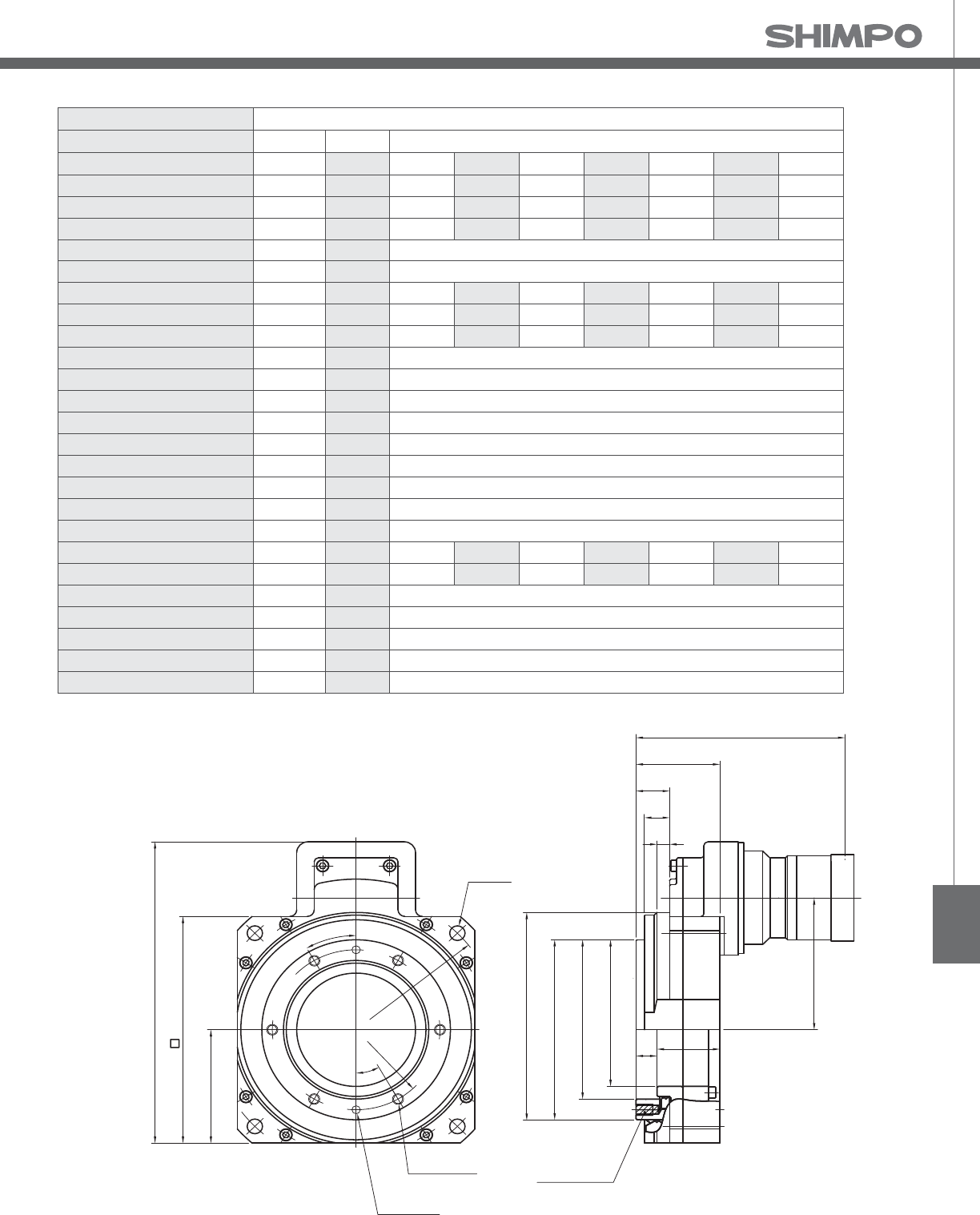
STH
226
170
85
60
24
18
98.8
6-M8x1.25
2-Ø6(H7)
Output Shaft
L
9
4-Ø11
Ø135(h8)
Ø176(h8)
Ø104(H8)
Ø85(Hollow Dia)
15 45
Ø120
Ø205
30°
12 Depth
8 Depth
30°
STHVL7 -Stage Specifications
STHVL7 -Stage Dimensions
Frame Size STHVL7
Stage Units Notes 3-Stage
Ratio -- *1 100:1 120:1 140:1 160:1 200:1 280:1 400:1
Nominal Torque 1 [Nm] *2 85 68 85 85 85 85 68
Acceleration Torque [Nm] -- 170 133 170 170 170 170 133
Emergency Stop Torque [Nm] -- 240 240 240 240 240 240 240
Nominal Input Speed [rpm] -- 3000
Max. Input Speed [rpm] -- 6000
Moment of Inertia (≤Ø 8) [kgcm2] *3 0.067 0.059 0.060 0.054 0.052 0.051 0.050
Moment of Inertia (≤Ø 14) [kgcm2] *3 0.144 0.140 0.137 0.135 0.133 0.132 0.131
Moment of Inertia (≤Ø 19) [kgcm2] *3 0.364 0.350 0.357 0.345 0.343 0.342 0.341
Backlash [arc-min] -- 2
Accuracy [arc-sec] -- ±60
Torsional Sti ness [Nm/arc-min] -- 7.6
Weight [kg] -- 7.8
Max. Axial Load [N] -- 4000
Max. Radial Load [N] -- 5000
Max. Tilting Moment Load [Nm] -- 200
Max. Surface Runout [mm] -- 0.070
Max. De ection [mm] -- 0.70
E ciency [%] -- 86 86 86 86 86 86 86
Noise Level [dB] -- 65 65 65 65 65 65 65
Max. Ambient Temperature °C -- 0-40
Max. Surface Temperature °C -- 90
Lubrication -- -- Grease
Protection -- *4 IP54 (IP65)
Unit Life hr -- 20000
*1) Contact NIDEC-SHIMPO for more optional ratios
*2) At nominal input speed
*3) At input shaft
*4) IP (wash-down) is available as an option. Contact NIDECSHIMPO for more details and our food grade options
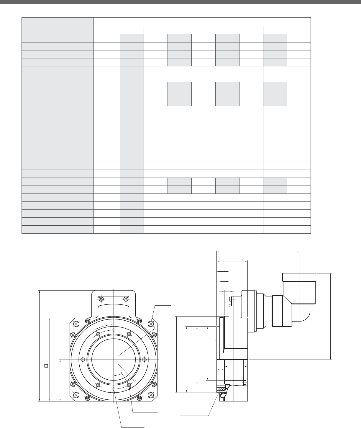
STH-SERIES Hollow output rotary actuators
226
170
85
Ø135(h8)
Ø176(h8)
Ø104(H8)
Ø85(Hollow Dia)
L
60
24
18
M
4-Ø11
6-M8x1.25
2-Ø6(H7)
Output Shaft
Ø120
Ø205
15
9
30°
30°
45
12 Depth
8 Depth
STHEL7 -Stage & 3-Stage Specifications
Frame Size STHEL7
Stage Units Notes 2-Stage 3-Stage
Ratio -- *1 12:1 16:1 20:1 28:1 40:1 60:1 80:1
Nominal Torque 1 [Nm] *2 43 58 84 85 61 61 85
Acceleration Torque [Nm] -- 86 115 152 170 122 122 170
Emergency Stop Torque [Nm] -- 180 234 240 240 204 240 240
Nominal Input Speed [rpm] -- 3000 3000
Max. Input Speed [rpm] -- 6000 6000
Moment of Inertia (≤Ø 8) [kgcm2] *3 1.280 0.811 0.597 0.412 0.314 0.112 0.093
Moment of Inertia (≤Ø 14) [kgcm2] *3 1.355 0.886 0.672 0.487 0.389 0.157 0.138
Moment of Inertia (≤Ø 19) [kgcm2] *3 1.544 1.075 0.862 0.676 0.578 -- --
Backlash [arc-min] -- 8 8
Accuracy [arc-sec] -- ±60 ±60
Torsional Sti ness [Nm/arc-min] -- 7.6 7.6
Weight [kg] -- 8.0 7.8
Max. Axial Load [N] -- 4000 4000
Max. Radial Load [N] -- 5000 5000
Max. Tilting Moment Load [Nm] -- 200 200
Max. Surface Runout [mm] -- 0.070 0.070
Max. De ection [mm] -- 0.70 0.70
E ciency [%] -- 84 84 88 88 88 84 84
Noise Level [dB] -- 72 72 65 65 65 65 65
Max. Ambient Temperature °C -- 0-40 0-40
Max. Surface Temperature °C -- 90 90
Lubrication -- -- Grease Grease
Protection -- *4 IP54 (IP65) IP54 (IP65)
Unit Life hr -- 20000 20000
STHEL7 -Stage & -Stage Dimensions
*1) Contact NIDEC-SHIMPO for more optional ratios
*2) At nominal input speed
*3) At input shaft
*4) IP (wash-down) is available as an option. Contact NIDECSHIMPO for more details and our food
grade options
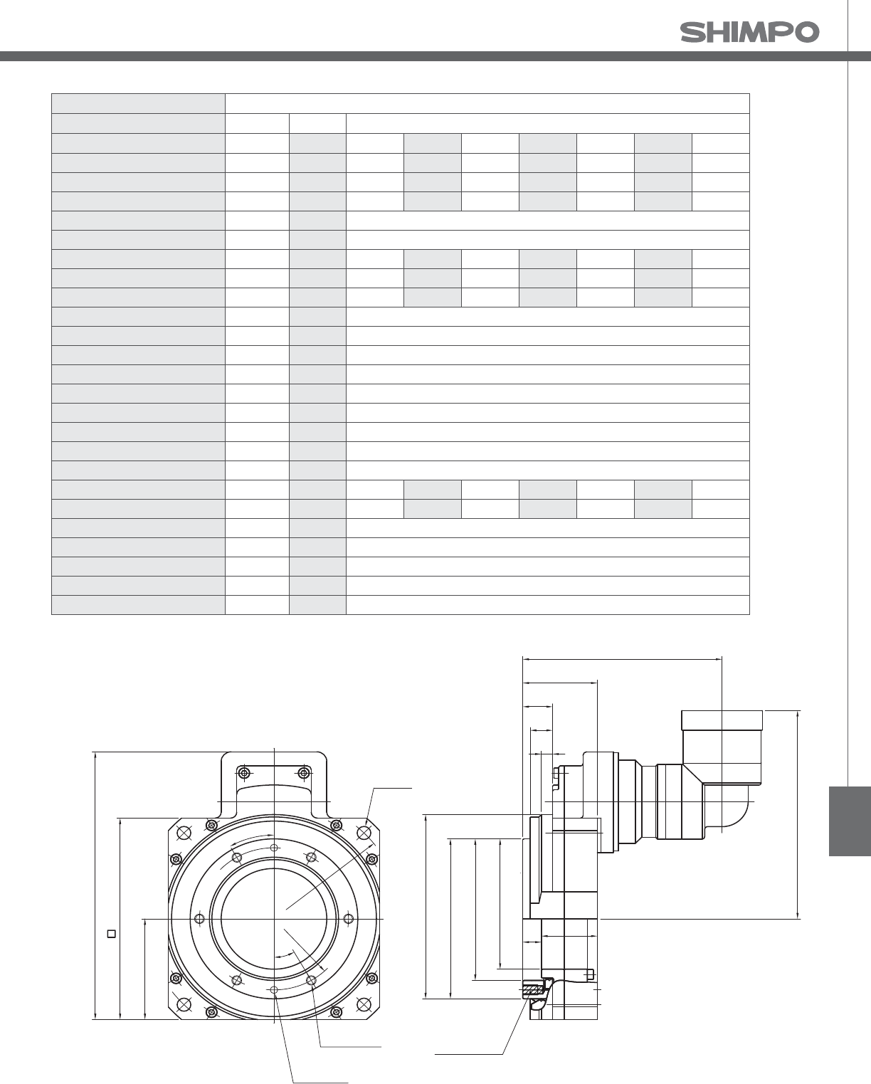
STH
226
170
85
Ø135(h8)
Ø176(h8)
Ø104(H8)
Ø85(Hollow Dia)
L
60
24
18
M
4-Ø11
6-M8x1.25
2-Ø6(H7)
Output Shaft
Ø120
Ø205
15
9
30°
30°
45
12 Depth
8 Depth
STHEL7 -Stage Specifications
Frame Size STHEL7
Stage Units Notes 3-Stage
Ratio -- *1 100:1 120:1 140:1 160:1 200:1 280:1 400:1
Nominal Torque 1 [Nm] *2 85 61 85 85 85 85 61
Acceleration Torque [Nm] -- 170 122 170 170 170 170 122
Emergency Stop Torque [Nm] -- 240 240 240 240 240 240 240
Nominal Input Speed [rpm] -- 3000
Max. Input Speed [rpm] -- 6000
Moment of Inertia (≤Ø 8) [kgcm2] *3 0.085 0.072 0.077 0.066 0.064 0.063 0.062
Moment of Inertia (≤Ø 14) [kgcm2] *3 0.129 0.116 0.122 0.111 0.108 0.106 0.106
Moment of Inertia (≤Ø 19) [kgcm2] *3 -- -- -- -- -- -- --
Backlash [arc-min] -- 8
Accuracy [arc-sec] -- ±60
Torsional Sti ness [Nm/arc-min] -- 7.6
Weight [kg] -- 7.8
Max. Axial Load [N] -- 4000
Max. Radial Load [N] -- 5000
Max. Tilting Moment Load [Nm] -- 200
Max. Surface Runout [mm] -- 0.070
Max. De ection [mm] -- 0.70
E ciency [%] -- 84 84 84 84 84 84 84
Noise Level [dB] -- 65 65 65 65 65 65 65
Max. Ambient Temperature °C -- 0-40
Max. Surface Temperature °C -- 90
Lubrication -- -- Grease
Protection -- *4 IP54 (IP65)
Unit Life hr -- 20000
STHEL7 -Stage Dimensions
*1) Contact NIDEC-SHIMPO for more optional ratios
*2) At nominal input speed
*3) At input shaft
*4) IP (wash-down) is available as an option. Contact NIDECSHIMPO for more details and our food
grade options

The STR provides a solution for ultra-high precision, obtain-
ing accuracies up to arc-seconds. The STR allows an ap-
plication to reach negligible backlash, maintain exceptional
rigidity, and maximize control stability so that the desired out-
put motion can be easily achieved. The design is truly a unique
concept, utilizing a full contact screw-like transmission for high-
efficiency and elimination of wear. The unit provides maximum
compactness using orthogonal axes and includes a large hollow
shaft for flexibility.
The STR will most often incorporate either an inline (VRB) or right-
angle (EVB) reducer to achieve an additional reduction and simplify
the connection to your servo motor. It is available in a number of
housing sizes, and it can handle extremely large moment loads. The
STR is an ideal fit for any automation or custom material handling
integrator that requires the precision, rigidity, and repeatability that
this servo rotary indexer can offer.
STR-SERIES

STR-SERIES
■Compatible with nearly any servo motor
■High output torque, high rigidity, high moment loads
■Large variety of reduction ratios to choose from
■Zero backlash, with precision as tight as arc-secs
■Large hollow shaft design allows use of air lines or wiring
■Multiple ratios to match application requirements
STR
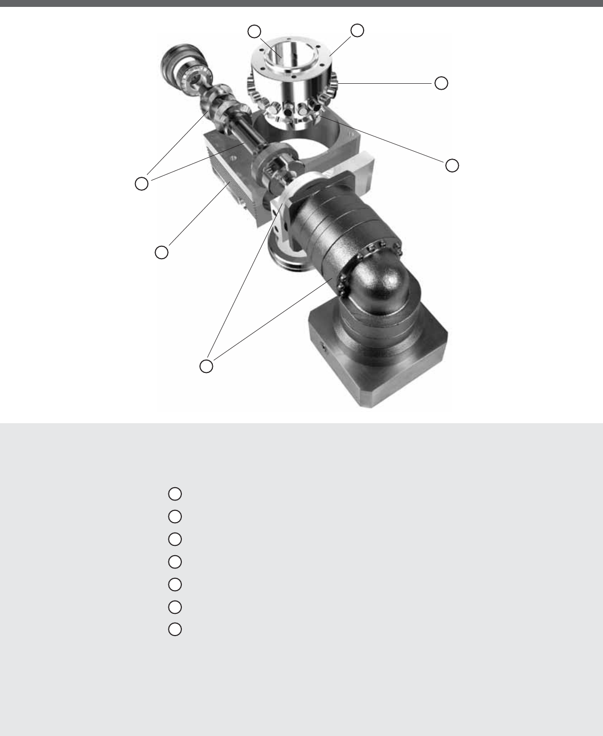
STR-SERIES Rotary indexer
STR-Series Features
7
1
1 Housing constructed from aluminum alloy
2 Special worm input shaft providing screw like transmission
3 Hollow-bore output shaft
4 Output shaft
5 Cam roller followers
6 Cross-roller bearing
7 Direct connection to VRB or EVB planetary reducer
4
2
3
5
6

STR
STR-Series Model Code
Contact us for additional information or refer to our online reducer selection tool.
Selection tool www.nidec-shimpo.co.jp/selection/eng
* Adapter ange code
Modications
STR
100 080 E R
Gearbox mount side (Right [R], Left [L])
Input Reducer type (Inline [V], Right-angle [E], None [N])
(Variety ranging from 15:1 - 2000:1)Reduction ratio
Actuator size (040, 063, 080, 100, 125, 160, 250)
Model name STR product
14BK12 00
*1) Adapter ange code
Adapter ange code varies depending on the motor.

STR-SERIES Rotary indexer
STR-V 1-Stage and 2-Stage Specifications with VRSF-B
*1) At nominal input speed
*2) Speeds are at the actuator input. Limits when used with additional gearbox are higher
*3) At input shaft
*4) IP (wash-down) is available as an option. Contact NIDECSHIMPO for more details and our food grade options
Frame Size 040V
Stage 1-Stage 2-Stage
Ratio Units Notes 15 45 75 135
Nominal Torque [Nm] *1 27 27 27 27
Acceleration Torque [Nm] -- 58 58 58 58
No Load Torque [Nm] *1 0.5 0.2 0.2 0.2
Nominal Input Speed [rpm] *2 900 2700 3000 3000
Maximum Input Speed [rpm] *2 3000 5000 5000 5000
Re ected Inertia (Single) [kg-mx10]*3 0.292 -- -- --
Re ected Inertia (≤Ø 8) [kg-mx10]*3 -- 0.082 0.06 0.053
Re ected Inertia (≤Ø 14) [kg-mx10]*3 -- 0.151 0.131 0.121
Backlash [arc-min] -- 0 0 0 0
Angular Transmission Accuracy [arc-min] -- ≤ 1.5 ≤ 1.5
Angular Repeatability Accuracy [arc-min] -- ± 0.2 ± 0.2
Surface Runout [µm (max)] -- 10 10 10 10
Weight [kg] -- 2.5 3.2 3.2 3.2
Maximum Axial Load [N] -- 999 999 999 999
Maximum Radial Load [N] -- 669 669 669 669
Maximum Tilting Moment Load [Nm] -- 33 33 33 33
E ciency [%] -- 80 76 76 76
Protection Class -- *4 IP54 (IP65)
6-M5 Depth10
V
47.5
95
0.5
62
65
Ø40
Ø55
Ø30 h7
Ø25
70
31
115
434032
1008
72
Ø25
17.5
21 ±0.05
27
122
40.5 ±0.1
81 ±0.03
65 ±0.1
INPUT FLANGE
OUTPUT TABLE SURFACE
Depth 10
S
W
R
V
Depth 10
***2-Ø5 H7 Depth8
(SURFACE V&W)
3-Ø6.9 DRILL THRU, Counterbore Ø11 Depth 6.5
3
-M
8
D
ept
h 1
5
R
U
T
***2-Ø5 H7 Depth8
VRSF-B
Ø42
Ø26
S
U
T
d
c
a
b
11.5
52 5
6101
52
**
SW
V
R
Ø60
4-Ø5.5 DRILL THRU
NOTE:
** Refer to page , for VRSF B-Frame dimensions
*** Optional
ROTATION:
a=d
a=c (upon special request)
STR- Dimensions with VRSF-B

STR
STR-V 3-Stage Specifications with VRSF-B
*1) At nominal input speed
*2) Speeds are at the actuator input. Limits when used with additional gearbox are higher
*3) At input shaft
*4) IP (wash-down) is available as an option. Contact NIDECSHIMPO for more details and our food grade options
Frame Size 040V
Stage 3-Stage
Ratio Units Notes 225 300 375 525
Nominal Torque [Nm] *1 27 27 27 27
Acceleration Torque [Nm] -- 58 58 58 58
No Load Torque [Nm] *1 0.1 0.1 0.1 0.1
Nominal Input Speed [rpm] *2 3000 3000 3000 3000
Maximum Input Speed [rpm] *2 5000 5000 5000 5000
Re ected Inertia (Single) [kg-mx10]*3 -- -- -- --
Re ected Inertia (≤Ø 8) [kg-mx10]*3 0.058 0.057 0.057 0.053
Re ected Inertia (≤Ø 14) [kg-mx10]*3 0.131 0.131 0.131 0.121
Backlash [arc-min] -- 0 0 0 0
Angular Transmission Accuracy [arc-min] -- ≤ 1.5
Angular Repeatability Accuracy [arc-min] -- ± 0.2
Surface Runout [µm (max)] -- 10 10 10 10
Weight [kg] -- 3.4 3.4 3.4 3.4
Maximum Axial Load [N] -- 999 999 999 999
Maximum Radial Load [N] -- 669 669 669 669
Maximum Tilting Moment Load [Nm] -- 33 33 33 33
E ciency [%] -- 72 72 72 72
Protection Class -- *4 IP54 (IP65)
6-M5 Depth10
V
47.5
95
0.5
62
65
Ø40
Ø55
Ø30 h7
Ø25
70
31
115
434032
1008
72
Ø25
17.5
21 ±0.05
27
122
40.5 ±0.1
81 ±0.03
65 ±0.1
INPUT FLANGE
OUTPUT TABLE SURFACE
Depth 10
S
W
R
V
Depth 10
***2-Ø5 H7 Depth8
(SURFACE V&W)
3-Ø6.9 DRILL THRU, Counterbore Ø11 Depth 6.5
3
-M
8
D
ept
h 1
5
R
U
T
***2-Ø5 H7 Depth8
VRSF-B
Ø42
Ø26
S
U
T
d
c
a
b
11.5
52 5
6101
52
**
SW
V
R
Ø60
4-Ø5.5 DRILL THRU
NOTE:
** Refer to page , for VRSF B-Frame dimensions
*** Optional
ROTATION:
a=d
a=c (upon special request)
STR- Dimensions with VRSF-B

STR-SERIES Rotary indexer
STR-V 2-Stage and 3-Stage Specifications with VRB-
STR-V 1-Stage and 2-Stage Specifications with VRB-
*1) At nominal input speed
*2) Speeds are at the actuator input. Limits when used with additional gearbox are higher
*3) At input shaft
*4) IP (wash-down) is available as an option. Contact NIDECSHIMPO for more details and our food grade options
*1) At nominal input speed
*2) Speeds are at the actuator input. Limits when used with additional gearbox are higher
*3) At input shaft
*4) IP (wash-down) is available as an option. Contact NIDECSHIMPO for more details and our food grade options
Frame Size 063V
Stage 1-Stage 2-Stage
Ratio Units Notes 20 60 80 100 120 140 160 180
Nominal Torque [Nm] *1 69 69 69 69 69 69 69 69
Acceleration Torque [Nm] -- 129 129 129 129 129 129 129 129
No Load Torque [Nm] *1 0.8 0.1 0.1 0.1 0.1 0.1 0.1 0.1
Nominal Input Speed [rpm] *2 800 2400 3000 3000 3000 3000 3000 3000
Maximum Input Speed [rpm] *2 3000 6000 6000 6000 6000 6000 6000 6000
Re ected Inertia (Single) [kg-mx10]*3 0.862 -- -- -- -- -- -- --
Re ected Inertia (≤Ø 8) [kg-mx10]*3 -- 0.142 0.097 0.079 0.070 0.064 0.061 0.059
Re ected Inertia (≤Ø 14) [kg-mx10]*3 -- 0.222 0.172 0.162 0.152 0.142 0.142 0.142
Re ected Inertia (≤Ø 19) [kg-mx10]*3 -- 0.432 0.382 0.362 0.362 0.352 0.352 0.342
Backlash [arc-min] -- 0 0 0 0 0 0 0 0
Angular Transmission Accuracy [arc-min] -- ≤ 1.0 ≤ 1.0
Angular Repeatability Accuracy [arc-min] -- ± 0.1 ± 0.1
Surface Runout [µm (max)] -- 10 10 10 10 10 10 10 10
Weight [kg] -- 5.6 7.0 7.0 7.0 7.0 7.0 7.0 7.0
Maximum Axial Load [N] -- 1657 1657 1657 1657 1657 1657 1657 1657
Maximum Radial Load [N] -- 1359 1359 1359 1359 1359 1359 1359 1359
Maximum Tilting Moment Load [Nm] -- 79 79 79 79 79 79 79 79
E ciency [%] -- 82 78 78 78 78 78 78 78
Protection Class -- *4 IP54 (IP65)
Frame Size 063V
Stage 2-Stage 3-Stage
Ratio Units Notes 200 300 320 400 500 560 600 700
Nominal Torque [Nm] *1 69 69 69 69 69 69 69 69
Acceleration Torque [Nm] -- 129 129 129 129 129 129 129 129
No Load Torque [Nm] *1 0.1 0.1 0.1 0.1 0.1 0.1 0.1 0.1
Nominal Input Speed [rpm] *2 3000 3000 3000 3000 3000 3000 3000 3000
Maximum Input Speed [rpm] *2 6000 6000 6000 6000 6000 6000 6000 6000
Re ected Inertia (Single) [kg-mx10]*3 -- -- -- -- -- --- --- ---
Re ected Inertia (≤Ø 8) [kg-mx10]*3 0.058 0.057 0.059 0.056 0.055 0.057 0.051 0.055
Re ected Inertia (≤Ø 14) [kg-mx10]*3 0.142 0.142 0.142 0.132 0.132 0.142 0.132 0.132
Re ected Inertia (≤Ø 19) [kg-mx10]*3 0.342 0.352 0.362 0.352 0.352 0.362 0.342 0.352
Backlash [arc-min] -- 0 0 0 0 0 0 0 0
Angular Transmission Accuracy [arc-min] -- ≤ 1.0 ≤ 1.0
Angular Repeatability Accuracy [arc-min] -- ± 0.1 ± 0.1
Surface Runout [µm (max)] -- 10 10 10 10 10 10 10 10
Weight [kg] -- 7.0 7.2 7.2 7.2 7.2 7.2 7.2 7.2
Maximum Axial Load [N] -- 1657 1657 1657 1657 1657 1657 1657 1657
Maximum Radial Load [N] -- 1359 1359 1359 1359 1359 1359 1359 1359
Maximum Tilting Moment Load [Nm] -- 79 79 79 79 79 79 79 79
E ciency [%] -- 78 74 74 74 74 74 74 74
Protection Class -- *4 IP54 (IP65)

STR
STR-V 3-Stage Specifications with VRB-
*1) At nominal input speed
*2) Speeds are at the actuator input. Limits when used with additional gearbox are higher
*3) At input shaft
*4) IP (wash-down) is available as an option. Contact NIDECSHIMPO for more details and our food grade options
Frame Size 063V
Stage 3-Stage
Ratio Units Notes 800 900 1000 1200 1400 1600 1800 2000
Nominal Torque [Nm] *1 69 69 69 69 69 69 69 69
Acceleration Torque [Nm] -- 129 129 129 129 129 129 129 129
No Load Torque [Nm] *1 0.1 0.1 0.1 0.1 0.1 0.1 0.1 0.1
Nominal Input Speed [rpm] *2 3000 3000 3000 3000 3000 3000 3000 3000
Maximum Input Speed [rpm] *2 6000 6000 6000 6000 6000 6000 6000 6000
Re ected Inertia (Single) [kg-mx10]*3 --- --- --- --- --- --- --- ---
Re ected Inertia (≤Ø 8) [kg-mx10]*3 0.051 0.055 0.051 0.051 0.051 0.051 0.051 0.051
Re ected Inertia (≤Ø 14) [kg-mx10]*3 0.132 0.132 0.132 0.132 0.132 0.132 0.132 0.132
Re ected Inertia (≤Ø 19) [kg-mx10]*3 0.342 0.352 0.342 0.342 0.342 0.342 0.342 0.342
Backlash [arc-min] -- 0 0 0 0 0 0 0 0
Angular Transmission Accuracy [arc-min] -- ≤ 1.0
Angular Repeatability Accuracy [arc-min] -- ± 0.1
Surface Runout [µm (max)] -- 10 10 10 10 10 10 10 10
Weight [kg] -- 7.2 7.2 7.2 7.2 7.2 7.2 7.2 7.2
Maximum Axial Load [N] -- 1657 1657 1657 1657 1657 1657 1657 1657
Maximum Radial Load [N] -- 1359 1359 1359 1359 1359 1359 1359 1359
Maximum Tilting Moment Load [Nm] -- 79 79 79 79 79 79 79 79
E ciency [%] -- 74 74 74 74 74 74 74 74
Protection Class -- *4 IP54 (IP65)
STR- Dimensions with VRB-
139.510.5
4-M5 Depth 10
V
Ø70
59 10.5
ba
104
52
10
R
95
606340
163
143
U
V
144.5
24.5
37.5
120
100 10
60
**
VRB-060
***2- Ø5 H7 Depth 8
3-Ø8.6 DRILL THRU, Counterbore Ø14 Depth 8.6
3-M10 Depth 15
(SURFACE V & W)
(SURFACE V & W)
*** Ø5 H7 Depth 8
6-M6 Depth12
cd
Ø
75
0.5
Ø70
Ø50 Depth 10
W
Ø90
Ø60 h7
Ø50 Depth 10
40
70
73
78
OUTPUT TABLE SURFACE
INPUT FLANGE
V
Ø51
±0.03
±0.05
±0.1
±0.1
**
S
W
NOTE:
** Refer to page , for VRB- dimensions
*** Optional
ROTATION:
a=d
a=c (upon special request)

STR-SERIES Rotary indexer
STR-E 1-Stage and 2-Stage Specifications with EVB-
STR-E 2Stage and 3-Stage Specifications with EVB-
*1) At nominal input speed
*2) Speeds are at the actuator input. Limits when used with additional gearbox are higher
*3) At input shaft
*4) IP (wash-down) is available as an option. Contact NIDECSHIMPO for more details and our food grade options
*1) At nominal input speed
*2) Speeds are at the actuator input. Limits when used with additional gearbox are higher
*3) At input shaft
*4) IP (wash-down) is available as an option. Contact NIDECSHIMPO for more details and our food grade options
Frame Size 063E
Stage 1-Stage 2-Stage
Ratio Units Notes 20 60 80 100 120 140 160 180
Nominal Torque [Nm] *1 69 69 69 69 69 69 69 69
Acceleration Torque [Nm] -- 129 129 129 129 129 129 129 129
No Load Torque [Nm] *1 0.8 0.4 0.4 0.4 0.4 0.4 0.4 0.4
Nominal Input Speed [rpm] *2 800 2400 3000 3000 3000 3000 3000 3000
Maximum Input Speed [rpm] *2 3000 6000 6000 6000 6000 6000 6000 6000
Re ected Inertia (Single) [kg-mx10]*3 0.862 -- -- -- -- -- -- --
Re ected Inertia (≤Ø 8) [kg-mx10]*3 -- 0.311 0.266 0.248 0.239 0.234 0.230 0.228
Re ected Inertia (≤Ø 14) [kg-mx10]*3 -- 0.386 0.341 0.323 0.314 0.309 0.305 0.303
Re ected Inertia (≤Ø 19) [kg-mx10]*3 -- 0.575 0.53 0.513 0.504 0.498 0.495 0.493
Backlash [arc-min] -- 0 0 0 0 0 0 0 0
Angular Transmission Accuracy [arc-min] -- ≤ 1.0 ≤ 1.0
Angular Repeatability Accuracy [arc-min] -- ± 0.1 ± 0.1
Surface Runout [µm (max)] -- 10 10 10 10 10 10 10 10
Weight [kg] -- 5.6 7.4 7.4 7.4 7.4 7.4 7.4 7.4
Maximum Axial Load [N] -- 1657 1657 1657 1657 1657 1657 1657 1657
Maximum Radial Load [N] -- 1359 1359 1359 1359 1359 1359 1359 1359
Maximum Tilting Moment Load [Nm] -- 79 79 79 79 79 79 79 79
E ciency [%] -- 82 74 74 74 74 74 74 74
Protection Class -- *4 IP54 (IP65)
Frame Size 063E
Stage 2-Stage 3-Stage
Ratio Units Notes 200 300 320 400 500 560 600 700
Nominal Torque [Nm] *1 69 69 69 69 69 69 69 69
Acceleration Torque [Nm] -- 129 129 129 129 129 129 129 129
No Load Torque [Nm] *1 0.4 0.2 0.2 0.2 0.2 0.2 0.2 0.2
Nominal Input Speed [rpm] *2 3000 3000 3000 3000 3000 3000 3000 3000
Maximum Input Speed [rpm] *2 6000 6000 6000 6000 6000 6000 6000 6000
Re ected Inertia (Single) [kg-mx10]*3 -- -- -- -- -- -- -- --
Re ected Inertia (≤Ø 8) [kg-mx10]*3 0.227 0.073 0.079 0.071 0.071 0.077 0.062 0.07
Re ected Inertia (≤Ø 14) [kg-mx10]*3 0.302 0.118 0.124 0.116 0.115 0.122 0.106 0.115
Re ected Inertia (≤Ø 19) [kg-mx10]*3 0.491 -- -- -- -- -- -- --
Backlash [arc-min] -- 0 0 0 0 0 0 0 0
Angular Transmission Accuracy [arc-min] -- ≤ 1.0 ≤ 1.0
Angular Repeatability Accuracy [arc-min] -- ± 0.1 ± 0.1
Surface Runout [µm (max)] -- 10 10 10 10 10 10 10 10
Weight [kg] -- 7.4 7.2 7.2 7.2 7.2 7.2 7.2 7.2
Maximum Axial Load [N] -- 1657 1657 1657 1657 1657 1657 1657 1657
Maximum Radial Load [N] -- 1359 1359 1359 1359 1359 1359 1359 1359
Maximum Tilting Moment Load [Nm] -- 79 79 79 79 79 79 79 79
E ciency [%] -- 74 70 70 70 70 70 70 70
Protection Class -- *4 IP54 (IP65)

STR
*1) At nominal input speed
*2) Speeds are at the actuator input. Limits when used with additional gearbox are higher
*3) At input shaft
*4) IP (wash-down) is available as an option. Contact NIDECSHIMPO for more details and our food grade options
Frame Size 063E
Stage 3-Stage
Ratio Units Notes 800 900 1000 1200 1400 1600 1800 2000
Nominal Torque [Nm] *1 69 69 69 69 69 69 69 69
Acceleration Torque [Nm] -- 129 129 129 129 129 129 129 129
No Load Torque [Nm] *1 0.2 0.2 0.2 0.2 0.2 0.2 0.2 0.2
Nominal Input Speed [rpm] *2 3000 3000 3000 3000 3000 3000 3000 3000
Maximum Input Speed [rpm] *2 6000 6000 6000 6000 6000 6000 6000 6000
Re ected Inertia (Single) [kg-mx10]*3 -- -- -- -- -- -- -- --
Re ected Inertia (≤Ø 8) [kg-mx10]*3 0.061 0.07 0.061 0.061 0.061 0.061 0.061 0.061
Re ected Inertia (≤Ø 14) [kg-mx10]*3 0.106 0.115 0.106 0.106 0.105 0.105 0.105 0.105
Re ected Inertia (≤Ø 19) [kg-mx10]*3 -- -- -- -- -- -- -- --
Backlash [arc-min] -- 0 0 0 0 0 0 0 0
Angular Transmission Accuracy [arc-min] -- ≤ 1.0
Angular Repeatability Accuracy [arc-min] -- ± 0.1
Surface Runout [µm (max)] -- 10 10 10 10 10 10 10 10
Weight [kg] -- 7.2 7.2 7.2 7.2 7.2 7.2 7.2 7.2
Maximum Axial Load [N] -- 1657 1657 1657 1657 1657 1657 1657 1657
Maximum Radial Load [N] -- 1359 1359 1359 1359 1359 1359 1359 1359
Maximum Tilting Moment Load [Nm] -- 79 79 79 79 79 79 79 79
E ciency [%] -- 70 70 70 70 70 70 70 70
Protection Class -- *4 IP54 (IP65)
STR-E -Stage Specifications with EVB-
0.5
Ø70
Ø90
Ø60 h7
Ø50 Depth 10
Ø50 Depth 10
Ø51
40
70
73
78
INPUT FLANGE
V
OUTPUT TABLE SURFACE
W
144.5
24.5
95 ±0.1
104 ±0.03
52±0.1
37.5
6063
120
40
163
10 143
100 10
60
V
*** 2-Ø 5H7 Depth 8
*** Ø5 H7 Depth 8
R
U
6-M6 Depth 12
cd
** EVB-060
Ø
75
**
**
3-Ø8.6 DRILL THRU, Counterbore Ø14 Depth 8.6
3-M10 Depth 15
(SURFACE V & W)
(SURFACE V & W)
59 10.5
139.510.5
ba
4-M5 Depth10
V
Ø
70
±0.05
S
W
NOTE:
** Refer to page , for EVB- dimensions
*** Optional
ROTATION:
a=d
a=c (upon special request)
STR- Dimensions with EVB-

STR-SERIES Rotary indexer
STR-V 1-Stage and 2-Stage Specifications with VRB-
Frame Size 080V
Stage 1-Stage 2-Stage
Ratio Units Notes 20 60 80 100 120 140 160 180
Nominal Torque [Nm] *1 113 113 113 113 113 113 113 113
Acceleration Torque [Nm] -- 202 202 202 202 202 202 202 202
No Load Torque [Nm] *1 1.3 0.1 0.1 0.1 0.1 0.1 0.1 0.1
Nominal Input Speed [rpm] *2 700 2100 2800 3000 3000 3000 3000 3000
Maximum Input Speed [rpm] *2 2500 6000 6000 6000 6000 6000 6000 6000
Re ected Inertia (Single) [kg-mx10]*3 3.066 -- -- -- -- -- -- --
Re ected Inertia (≤Ø 8) [kg-mx10]*3 -- 0.148 0.103 0.085 0.076 0.070 0.067 0.065
Re ected Inertia (≤Ø 14) [kg-mx10-4] *3 -- 0.228 0.178 0.168 0.158 0.148 0.148 0.148
Re ected Inertia (≤Ø 19) [kg-mx10]*3 -- 0.438 0.388 0.368 0.368 0.358 0.358 0.348
Backlash [arc-min] -- 0 0 0 0 0 0 0 0
Angular Transmission Accuracy [arc-min] -- ≤ 0.7 ≤ 0.7
Angular Repeatability Accuracy [arc-min] -- ± 0.08 ± 0.08
Surface Runout [µm (max)] -- 10 10 10 10 10 10 10 10
Weight [kg] -- 11.6 13.0 13.0 13.0 13.0 13.0 13.0 13.0
Maximum Axial Load [N] -- 3302 3302 3302 3302 3302 3302 3302 3302
Maximum Radial Load [N] -- 2819 2819 2819 2819 2819 2819 2819 2819
Maximum Tilting Moment Load [Nm] -- 210 210 210 210 210 210 210 210
E ciency [%] -- 80 76 76 76 76 76 76 76
Protection Class -- *4 IP54 (IP65)
Frame Size 080V
Stage 2-Stage 3-Stage
Ratio Units Notes 200 300 320 400 500 560 600 700
Nominal Torque [Nm] *1 113 113 113 113 113 113 113 113
Acceleration Torque [Nm] -- 202 202 202 202 202 202 202 202
No Load Torque [Nm] *1 0.1 0.1 0.1 0.1 0.1 0.1 0.1 0.1
Nominal Input Speed [rpm] *2 3000 3000 3000 3000 3000 3000 3000 3000
Maximum Input Speed [rpm] *2 6000 6000 6000 6000 6000 6000 6000 6000
Re ected Inertia (Single) [kg-mx10]*3 -- -- -- -- -- -- -- --
Re ected Inertia (≤Ø 8) [kg-mx10]*3 0.064 0.063 0.065 0.062 0.061 0.063 0.057 0.061
Re ected Inertia (≤Ø 14) [kg-mx10-4] *3 0.148 0.148 0.148 0.138 0.138 0.148 0.138 0.138
Re ected Inertia (≤Ø 19) [kg-mx10]*3 0.348 0.358 0.368 0.358 0.358 0.368 0.348 0.358
Backlash [arc-min] -- 0 0 0 0 0 0 0 0
Angular Transmission Accuracy [arc-min] -- ≤ 0.7 ≤ 0.7
Angular Repeatability Accuracy [arc-min] -- ± 0.08 ± 0.08
Surface Runout [µm (max)] -- 10 10 10 10 10 10 10 10
Weight [kg] -- 13.0 13.2 13.2 13.2 13.2 13.2 13.2 13.2
Maximum Axial Load [N] -- 3302 3302 3302 3302 3302 3302 3302 3302
Maximum Radial Load [N] -- 2819 2819 2819 2819 2819 2819 2819 2819
Maximum Tilting Moment Load [Nm] -- 210 210 210 210 210 210 210 210
E ciency [%] -- 76 72 72 72 72 72 72 72
Protection Class -- *4 IP54 (IP65)
STR-V 2-Stage and 3-Stage Specifications with VRB-
*1) At nominal input speed
*2) Speeds are at the actuator input. Limits when used with additional gearbox are higher
*3) At input shaft
*4) IP (wash-down) is available as an option. Contact NIDECSHIMPO for more details and our food grade options
*1) At nominal input speed
*2) Speeds are at the actuator input. Limits when used with additional gearbox are higher
*3) At input shaft
*4) IP (wash-down) is available as an option. Contact NIDECSHIMPO for more details and our food grade options

STR
STR-V -Stage Specifications with VRB-
Frame Size 080V
Stage 3-Stage
Ratio Units Notes 800 900 1000 1200 1400 1600 1800 2000
Nominal Torque [Nm] *1 113 113 113 113 113 113 113 113
Acceleration Torque [Nm] -- 202 202 202 202 202 202 202 202
No Load Torque [Nm] *1 0.1 0.1 0.1 0.1 0.1 0.1 0.1 0.1
Nominal Input Speed [rpm] *2 3000 3000 3000 3000 3000 3000 3000 3000
Maximum Input Speed [rpm] *2 6000 6000 6000 6000 6000 6000 6000 6000
Re ected Inertia (Single) [kg-mx10]*3 -- -- -- -- -- -- -- --
Re ected Inertia (≤Ø 8) [kg-mx10]*3 0.057 0.061 0.057 0.057 0.057 0.057 0.057 0.057
Re ected Inertia (≤Ø 14) [kg-mx10-4] *3 0.138 0.138 0.138 0.138 0.138 0.138 0.138 0.138
Re ected Inertia (≤Ø 19) [kg-mx10]*3 0.348 0.358 0.348 0.348 0.348 0.348 0.348 0.348
Backlash [arc-min] -- 0 0 0 0 0 0 0 0
Angular Transmission Accuracy [arc-min] -- ≤ 0.7
Angular Repeatability Accuracy [arc-min] -- ± 0.08
Surface Runout [µm (max)] -- 10 10 10 10 10 10 10 10
Weight [kg] -- 13.2 13.2 13.2 13.2 13.2 13.2 13.2 13.2
Maximum Axial Load [N] -- 3302 3302 3302 3302 3302 3302 3302 3302
Maximum Radial Load [N] -- 2819 2819 2819 2819 2819 2819 2819 2819
Maximum Tilting Moment Load [Nm] -- 210 210 210 210 210 210 210 210
E ciency [%] -- 72 72 72 72 72 72 72 72
Protection Class -- *4 IP54 (IP65)
*1) At nominal input speed
*2) Speeds are at the actuator input. Limits when used with additional gearbox are higher
*3) At input shaft
*4) IP (wash-down) is available as an option. Contact NIDECSHIMPO for more details and our food grade options
STR-V Dimensions with VRB-
T
T
a
b
W
V
4-M5 Depth 10
12.579
10.5 184.5
d
c
V
*** 2-Ø5 H7 Depth 8
(SURFACE V OR W )
*** Ø5 H7 Depth 8
** VRB-060
6-M8 Depth16
R
3-Ø10.5 DRILL THRU, Counterbore Ø17.5 Depth 10.8
3-M12 Depth 18
(SURFACE V & W )
194±0.00
74±0.1
8080
186
12
210
50
U
Ø102
125±0.00
55±0.1
51±0.00 80
12
160
136
28.5
188.5
**
S
INPUT FLANGE
V
W
OUTPUT TABLE SURFACE
100
95
92
52
Ø75 Depth15
Ø85 h7
Ø120
Ø76
0.5
Ø95
Ø75 Depth 15
U
NOTE:
** Refer to page , for VRB- dimensions
*** Optional
ROTATION:
a=d
a=c (upon special request)

STR-SERIES Rotary indexer
STR-E 1-Stage and 2-Stage Specifications with EVB-
Frame Size 080E
Stage 1-Stage 2-Stage
Ratio Units Notes 20 60 80 100 120 140 160 180
Nominal Torque [Nm] *1 113 113 113 113 113 113 113 113
Acceleration Torque [Nm] -- 202 202 202 202 202 202 202 202
No Load Torque [Nm] *1 1.3 0.4 0.4 0.4 0.4 0.4 0.4 0.4
Nominal Input Speed [rpm] *2 700 2100 2800 3000 3000 3000 3000 3000
Maximum Input Speed [rpm] *2 2500 6000 6000 6000 6000 6000 6000 6000
Re ected Inertia (Single) [kg-mx10]*3 3.066 -- -- -- -- -- -- --
Re ected Inertia (≤Ø 8) [kg-mx10]*3 -- 0.319 0.274 0.256 0.247 0.242 0.238 0.236
Re ected Inertia (≤Ø 14) [kg-mx10]*3 -- 0.394 0.349 0.331 0.322 0.317 0.313 0.311
Re ected Inertia (≤Ø 19) [kg-mx10]*3 -- 0.583 0.538 0.521 0.512 0.506 0.503 0.501
Backlash [arc-min] -- 0 0 0 0 0 0 0 0
Angular Transmission Accuracy [arc-min] -- ≤ 0.7 ≤ 0.7
Angular Repeatability Accuracy [arc-min] -- ± 0.08 ± 0.08
Surface Runout [µm (max)] -- 10 10 10 10 10 10 10 10
Weight [kg] -- 11.6 13.4 13.4 13.4 13.4 13.4 13.4 13.4
Maximum Axial Load [N] -- 3302 3302 3302 3302 3302 3302 3302 3302
Maximum Radial Load [N] -- 2819 2819 2819 2819 2819 2819 2819 2819
Maximum Tilting Moment Load [Nm] -- 210 210 210 210 210 210 210 210
E ciency [%] -- 80 72 72 72 72 72 72 72
Protection Class -- *4 IP54 (IP65)
Frame Size 080E
Stage 2-Stage 3-Stage
Ratio Units Notes 200 300 320 400 500 560 600 700
Nominal Torque [Nm] *1 113 113 113 113 113 113 113 113
Acceleration Torque [Nm] -- 202 202 202 202 202 202 202 202
No Load Torque [Nm] *1 0.4 0.3 0.3 0.3 0.3 0.3 0.3 0.3
Nominal Input Speed [rpm] *2 3000 3000 3000 3000 3000 3000 3000 3000
Maximum Input Speed [rpm] *2 6000 6000 6000 6000 6000 6000 6000 6000
Re ected Inertia (Single) [kg-mx10]*3 -- -- -- -- -- -- -- --
Re ected Inertia (≤Ø 8) [kg-mx10]*3 0.235 0.081 0.087 0.079 0.079 0.085 0.070 0.078
Re ected Inertia (≤Ø 14) [kg-mx10]*3 0.310 0.126 0.132 0.124 0.123 0.130 0.114 0.123
Re ected Inertia (≤Ø 19) [kg-mx10]*3 0.499 -- -- -- -- -- -- --
Backlash [arc-min] -- 0 0 0 0 0 0 0 0
Angular Transmission Accuracy [arc-min] -- ≤ 0.7 ≤ 0.7
Angular Repeatability Accuracy [arc-min] -- ± 0.08 ± 0.08
Surface Runout [µm (max)] -- 10 10 10 10 10 10 10 10
Weight [kg] -- 13.4 13.2 13.2 13.2 13.2 13.2 13.2 13.2
Maximum Axial Load [N] -- 3302 3302 3302 3302 3302 3302 3302 3302
Maximum Radial Load [N] -- 2819 2819 2819 2819 2819 2819 2819 2819
Maximum Tilting Moment Load [Nm] -- 210 210 210 210 210 210 210 210
E ciency [%] -- 72 68 68 68 68 68 68 68
Protection Class -- *4 IP54 (IP65)
STR-E 2-Stage and 3-Stage Specifications with EVB-
*1) At nominal input speed
*2) Speeds are at the actuator input. Limits when used with additional gearbox are higher
*3) At input shaft
*4) IP (wash-down) is available as an option. Contact NIDECSHIMPO for more details and our food grade options
*1) At nominal input speed
*2) Speeds are at the actuator input. Limits when used with additional gearbox are higher
*3) At input shaft
*4) IP (wash-down) is available as an option. Contact NIDECSHIMPO for more details and our food grade options

STR
Frame Size 080E
Stage 3-Stage
Ratio Units Notes 800 900 1000 1200 1400 1600 1800 2000
Nominal Torque [Nm] *1 113 113 113 113 113 113 113 113
Acceleration Torque [Nm] -- 202 202 202 202 202 202 202 202
No Load Torque [Nm] *1 0.3 0.3 0.3 0.3 0.3 0.3 0.3 0.3
Nominal Input Speed [rpm] *2 3000 3000 3000 3000 3000 3000 3000 3000
Maximum Input Speed [rpm] *2 6000 6000 6000 6000 6000 6000 6000 6000
Re ected Inertia (Single) [kg-mx10]*3 -- -- -- -- -- -- -- --
Re ected Inertia (≤Ø 8) [kg-mx10]*3 0.069 0.078 0.069 0.069 0.069 0.069 0.069 0.069
Re ected Inertia (≤Ø 14) [kg-mx10]*3 0.114 0.123 0.114 0.114 0.113 0.113 0.113 0.113
Re ected Inertia (≤Ø 19) [kg-mx10]*3 -- -- -- -- -- -- -- --
Backlash [arc-min] -- 0 0 0 0 0 0 0 0
Angular Transmission Accuracy [arc-min] -- ≤ 0.7
Angular Repeatability Accuracy [arc-min] -- ± 0.08
Surface Runout [µm (max)] -- 10 10 10 10 10 10 10 10
Weight [kg] -- 13.2 13.2 13.2 13.2 13.2 13.2 13.2 13.2
Maximum Axial Load [N] -- 3302 3302 3302 3302 3302 3302 3302 3302
Maximum Radial Load [N] -- 2819 2819 2819 2819 2819 2819 2819 2819
Maximum Tilting Moment Load [Nm] -- 210 210 210 210 210 210 210 210
E ciency [%] -- 68 68 68 68 68 68 68 68
Protection Class -- *4 IP54 (IP65)
STR-E 3-Stage Specifications with EVB-
STR-E Dimensions with EVB-
*1) At nominal input speed
*2) Speeds are at the actuator input. Limits when used with additional gearbox are higher
*3) At input shaft
*4) IP (wash-down) is available as an option. Contact NIDECSHIMPO for more details and our food grade options
T
a
b
W
V
4-M5 Depth 10
12.579
10.5 184.5
cd
V
*** 2-Ø5 H7 Depth 8
(SURFACE V OR W )
*** Ø5 H7 Depth 8
** VRB-060
6-M8 Depth 16
R
3-Ø10.5 DRILL THRU, Counterbore Ø17.5 Depth 10.8
3-M12 Depth 18
(SURFACE V & W )
80
12
51±0.00
160
136
28.5
188.5
S
**
194±0.00
74±0.1
125±0.00
55±0.1
8080
186
12
210
50
U
Ø102
INPUT FLANGE
V
W
OUTPUT TABLE SURFACE
100
95
92
52
0.5
Ø95
Ø75 Depth 15
Ø75 Depth 15
Ø85 h7
Ø120
Ø76
U
T
**
NOTE:
** Refer to page , for EVB- dimensions
*** Optional
ROTATION:
a=d
a=c (upon special request)

STR-SERIES Rotary indexer
STR-V 1-Stage and 2-Stage Specifications with VRB-
Frame Size 100V
Stage 1-Stage 2-Stage
Ratio Units Notes 20 60 80 100 120 140 160 180
Nominal Torque [Nm] *1 330 330 330 330 330 330 330 330
Acceleration Torque [Nm] -- 565 565 565 565 565 565 565 565
No Load Torque [Nm] *1 2.6 0.3 0.3 0.3 0.3 0.3 0.3 0.3
Nominal Input Speed [rpm] *2 600 1800 2400 3000 3000 3000 3000 3000
Maximum Input Speed [rpm] *2 2000 6000 6000 6000 6000 6000 6000 6000
Re ected Inertia (Single) [kg-mx10]*3 8.687 -- -- -- -- -- -- --
Re ected Inertia (≤Ø 8) [kg-mx10]*3 -- -- -- -- -- -- -- --
Re ected Inertia (≤Ø 14) [kg-mx10]*3 -- 0.742 0.512 0.422 0.382 0.342 0.332 0.312
Re ected Inertia (≤Ø 19) [kg-mx10]*3 -- 1.222 0.972 0.882 0.842 0.812 0.792 0.782
Re ected Inertia (≤Ø 28) [kg-mx10]*3 -- 3.222 3.022 2.922 2.822 2.822 2.822 2.822
Backlash [arc-min] -- 0 0 0 0 0 0 0 0
Angular Transmission Accuracy [arc-min] -- ≤ 0.7 ≤ 0.7
Angular Repeatability Accuracy [arc-min] -- ± 0.08 ± 0.08
Surface Runout [µm (max)] -- 10 10 10 10 10 10 10 10
Weight [kg] -- 21.5 25.2 25.2 25.2 25.2 25.2 25.2 25.2
Maximum Axial Load [N] -- 3724 3724 3724 3724 3724 3724 3724 3724
Maximum Radial Load [N] -- 3109 3109 3109 3109 3109 3109 3109 3109
Maximum Tilting Moment Load [Nm] -- 284 284 284 284 284 284 284 284
E ciency [%] -- 82 78 78 78 78 78 78 78
Protection Class IP54 (IP65)
Frame Size 100V
Stage 2-Stage 3-Stage
Ratio Units Notes 200 300 320 400 500 560 600 700
Nominal Torque [Nm] *1 330 330 330 330 330 330 330 330
Acceleration Torque [Nm] -- 565 565 565 565 565 565 565 565
No Load Torque [Nm] *1 0.3 0.2 0.2 0.2 0.2 0.2 0.2 0.2
Nominal Input Speed [rpm] *2 3000 3000 3000 3000 3000 3000 3000 3000
Maximum Input Speed [rpm] *2 6000 6000 6000 6000 6000 6000 6000 6000
Re ected Inertia (Single) [kg-mx10]*3 -- -- -- -- -- -- -- --
Re ected Inertia (≤Ø 8) [kg-mx10]*3 -- 0.152 0.172 0.152 0.142 0.162 0.122 0.142
Re ected Inertia (≤Ø 14) [kg-mx10]*3 0.312 0.302 0.322 0.302 0.302 0.312 0.272 0.292
Re ected Inertia (≤Ø 19) [kg-mx10]*3 0.772 0.742 0.762 0.742 0.732 0.752 0.722 0.732
Re ected Inertia (≤Ø 28) [kg-mx10]*3 2.822 2.722 2.822 2.722 2.722 2.722 2.622 2.722
Backlash [arc-min] -- 0 0 0 0 0 0 0 0
Angular Transmission Accuracy [arc-min] -- ≤ 0.7 ≤ 0.7
Angular Repeatability Accuracy [arc-min] -- ± 0.08 ± 0.08
Surface Runout [µm (max)] -- 10 10 10 10 10 10 10 10
Weight [kg] -- 25.2 25.7 25.7 25.7 25.7 25.7 25.7 25.7
Maximum Axial Load [N] -- 3724 3724 3724 3724 3724 3724 3724 3724
Maximum Radial Load [N] -- 3109 3109 3109 3109 3109 3109 3109 3109
Maximum Tilting Moment Load [Nm] -- 284 284 284 284 284 284 284 284
E ciency [%] -- 78 74 74 74 74 74 74 74
Protection Class IP54 (IP65)
STR-V 2-Stage and 3-Stage Specifications with VRB-
*1) At nominal input speed
*2) Speeds are at the actuator input. Limits when used with additional gearbox are higher
*3) At input shaft
*4) IP (wash-down) is available as an option. Contact NIDECSHIMPO for more details and our food grade options
*1) At nominal input speed
*2) Speeds are at the actuator input. Limits when used with additional gearbox are higher
*3) At input shaft
*4) IP (wash-down) is available as an option. Contact NIDECSHIMPO for more details and our food grade options

STR
Frame Size 100V
Stage 3-Stage
Ratio Units Notes 800 900 1000 1200 1400 1600 1800 2000
Nominal Torque [Nm] *1 330 330 330 330 330 330 330 330
Acceleration Torque [Nm] -- 565 565 565 565 565 565 565 565
No Load Torque [Nm] *1 0.2 0.2 0.2 0.2 0.2 0.2 0.2 0.2
Nominal Input Speed [rpm] *2 3000 3000 3000 3000 3000 3000 3000 3000
Maximum Input Speed [rpm] *2 6000 6000 6000 6000 6000 6000 6000 6000
Re ected Inertia (Single) [kg-mx10]*3 -- -- -- -- -- -- -- --
Re ected Inertia (≤Ø 8) [kg-mx10]*3 0.121 0.142 0.120 0.120 0.119 0.119 0.119 0.119
Re ected Inertia (≤Ø 14) [kg-mx10]*3 0.272 0.292 0.272 0.272 0.272 0.272 0.272 0.272
Re ected Inertia (≤Ø 19) [kg-mx10]*3 0.722 0.732 0.712 0.712 0.712 0.712 0.712 0.712
Re ected Inertia (≤Ø 28) [kg-mx10]*3 2.622 2.722 2.622 2.622 2.622 2.622 2.622 2.622
Backlash [arc-min] -- 0 0 0 0 0 0 0 0
Angular Transmission Accuracy [arc-min] -- ≤ 0.7
Angular Repeatability Accuracy [arc-min] -- ± 0.08
Surface Runout [µm (max)] -- 10 10 10 10 10 10 10 10
Weight [kg] -- 25.7 25.7 25.7 25.7 25.7 25.7 25.7 25.7
Maximum Axial Load [N] -- 3724 3724 3724 3724 3724 3724 3724 3724
Maximum Radial Load [N] -- 3109 3109 3109 3109 3109 3109 3109 3109
Maximum Tilting Moment Load [Nm] -- 284 284 284 284 284 284 284 284
E ciency [%] -- 74 74 74 74 74 74 74 74
Protection Class IP54 (IP65)
STR-V 1-Stage and 3-Stage Specifications with VRB-
*1) At nominal input speed
*2) Speeds are at the actuator input. Limits when used with additional gearbox are higher
*3) At input shaft
*4) IP (wash-down) is available as an option. Contact NIDECSHIMPO for more details and our food grade options
STR- Dimensions with VRB-
10.599
10.5 227
99
4-M6 Depth 12
W
Ø100
V
a
b
T
15
95
190
160
60 ±1.27
32.5
222.5
** VRB-090
T
S
6-M10 Depth 20
Ø5H7 Depth 8
100 95
255
60
22515
89 ±2.5
239 ±0.76
U
***2-Ø5h7 Depth 8
(SURFACE V & W)
4-Ø10.5 DRILL THRU, Counterbore Ø17.5 Depth 10.8
4-M12 Depth 20
(SURFACE V & W)
45
100
66±2.5
151
R
Ø120 mm
V
cd
±0.76
122
115
110
60
OUTPUT TABLE SURFACE
INPUT FLANGE
Ø86
Ø145
Ø95 h7
Ø
85 Depth 15
(0.5)
Ø85 Depth 15
Ø110
U
WV
**
NOTE:
** Refer to page , for VRB- dimensions
*** Optional
ROTATION:
a=d
a=c (upon special request)

STR-SERIES Rotary indexer
Frame Size 100E
Stage 1-Stage 2-Stage
Ratio Units Notes 20 60 80 100 120 140 160 180
Nominal Torque [Nm] *1 330 330 330 330 330 330 330 330
Acceleration Torque [Nm] -- 565 565 565 565 565 565 565 565
No Load Torque [Nm] *1 2.6 1.3 1.3 1.3 1.3 1.3 1.3 1.3
Nominal Input Speed [rpm] *2 600 1800 2400 3000 3000 3000 3000 3000
Maximum Input Speed [rpm] *2 2000 6000 6000 6000 6000 6000 6000 6000
Re ected Inertia [kg-mx10]*3 8.687 -- -- -- -- -- -- --
Re ected Inertia (≤Ø 8) [kg-mx10]*3 -- -- -- -- -- -- -- --
Re ected Inertia (≤Ø 14) [kg-mx10]*3 -- 2.132 1.912 1.822 1.782 1.752 1.732 1.722
Re ected Inertia (≤Ø 19) [kg-m2x10]*3 -- 2.462 2.242 2.152 2.112 2.082 2.062 2.052
Re ected Inertia (≤Ø 28) [kg-mx10]*3 -- 4.592 4.372 4.282 4.232 4.202 4.192 4.182
Backlash [arc-min] -- 0 0 0 0 0 0 0 0
Angular Transmission Accuracy [arc-min] -- ≤ 0.7 ≤ 0.7
Angular Repeatability Accuracy [arc-min] -- ± 0.08 ± 0.08
Surface Runout [µm (max)] -- 10 10 10 10 10 10 10 10
Weight [kg] -- 21.5 26.6 26.6 26.6 26.6 26.6 26.6 26.6
Maximum Axial Load [N] -- 3724 3724 3724 3724 3724 3724 3724 3724
Maximum Radial Load [N] -- 3109 3109 3109 3109 3109 3109 3109 3109
Maximum Tilting Moment Load [Nm] -- 284 284 284 284 284 284 284 284
E ciency [%] -- 82 74 74 74 74 74 74 74
Protection Class -- *4 IP54 (IP65)
Frame Size 100E
Stage 2-Stage 3-Stage
Ratio Units Notes 200 300 320 400 500 560 600 700
Nominal Torque [Nm] *1 330 330 330 330 330 330 330 330
Acceleration Torque [Nm] -- 565 565 565 565 565 565 565 565
No Load Torque [Nm] *1 1.3 0.7 0.7 0.7 0.7 0.7 0.7 0.7
Nominal Input Speed [rpm] *2 3000 3000 3000 3000 3000 3000 3000 3000
Maximum Input Speed [rpm] *2 6000 6000 6000 6000 6000 6000 6000 6000
Re ected Inertia [kg-mx10]*3 -- -- -- -- -- -- -- --
Re ected Inertia (≤Ø 8) [kg-mx10]*3 -- 0.362 0.402 0.352 0.342 0.392 0.272 0.342
Re ected Inertia (≤Ø 14) [kg-mx10]*3 1.712 0.432 0.482 0.422 0.422 0.472 0.352 0.422
Re ected Inertia (≤Ø 19) [kg-m2x10]*3 2.042 0.622 0.672 0.612 0.612 0.662 0.532 0.612
Re ected Inertia (≤Ø 28) [kg-mx10]*3 4.172 -- -- -- -- -- -- --
Backlash [arc-min] -- 0 0 0 0 0 0 0 0
Angular Transmission Accuracy [arc-min] -- ≤ 0.7 ≤ 0.7
Angular Repeatability Accuracy [arc-min] -- ± 0.08 ± 0.08
Surface Runout [µm (max)] -- 10 10 10 10 10 10 10 10
Weight [kg] -- 26.6 25.9 25.9 25.9 25.9 25.9 25.9 25.9
Maximum Axial Load [N] -- 3724 3724 3724 3724 3724 3724 3724 3724
Maximum Radial Load [N] -- 3109 3109 3109 3109 3109 3109 3109 3109
Maximum Tilting Moment Load [Nm] -- 284 284 284 284 284 284 284 284
E ciency [%] -- 74 70 70 70 70 70 70 70
Protection Class -- *4 IP54 (IP65)
STR-E 1-Stage and 2-Stage Specifications with EVB-
STR-E 2-Stage and 3-Stage Specifications with EVB-
*1) At nominal input speed
*2) Speeds are at the actuator input. Limits when used with additional gearbox are higher
*3) At input shaft
*4) IP (wash-down) is available as an option. Contact NIDECSHIMPO for more details and our food grade options
*1) At nominal input speed
*2) Speeds are at the actuator input. Limits when used with additional gearbox are higher
*3) At input shaft
*4) IP (wash-down) is available as an option. Contact NIDECSHIMPO for more details and our food grade options
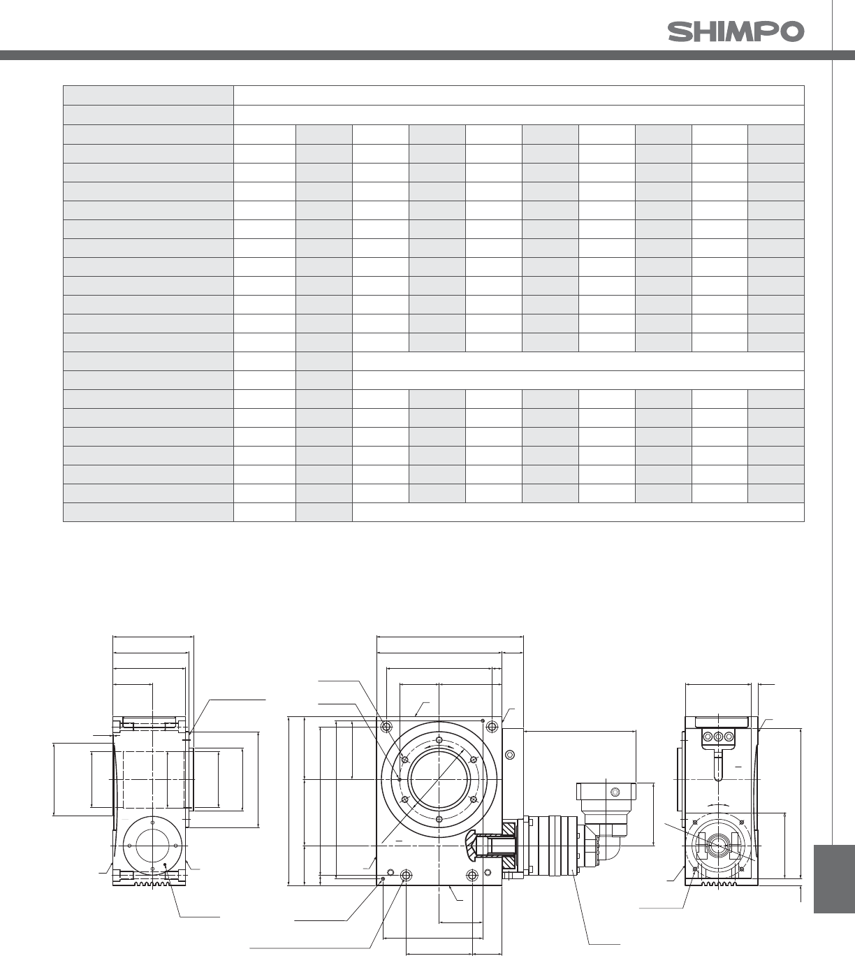
STR
Frame Size 100E
Stage 3-Stage
Ratio Units Notes 800 900 1000 1200 1400 1600 1800 2000
Nominal Torque [Nm] *1 330 330 330 330 330 330 330 330
Acceleration Torque [Nm] -- 565 565 565 565 565 565 565 565
No Load Torque [Nm] *1 0.7 0.7 0.7 0.7 0.7 0.7 0.7 0.7
Nominal Input Speed [rpm] *2 3000 3000 3000 3000 3000 3000 3000 3000
Maximum Input Speed [rpm] *2 6000 6000 6000 6000 6000 6000 6000 6000
Re ected Inertia [kg-mx10]*3 -- -- -- -- -- -- -- --
Re ected Inertia (≤Ø 8) [kg-mx10]*3 0.272 0.342 0.272 0.272 0.272 0.272 0.272 0.272
Re ected Inertia (≤Ø 14) [kg-mx10]*3 0.342 0.412 0.342 0.342 0.342 0.342 0.342 0.342
Re ected Inertia (≤Ø 19) [kg-m2x10]*3 0.532 0.602 0.532 0.532 0.532 0.532 0.532 0.532
Re ected Inertia (≤Ø 28) [kg-mx10]*3 -- -- -- -- -- -- -- --
Backlash [arc-min] -- 0 0 0 0 0 0 0 0
Angular Transmission Accuracy [arc-min] -- ≤ 0.7
Angular Repeatability Accuracy [arc-min] -- ± 0.08
Surface Runout [µm (max)] -- 10 10 10 10 10 10 10 10
Weight [kg] -- 25.9 25.9 25.9 25.9 25.9 25.9 25.9 25.9
Maximum Axial Load [N] -- 3724 3724 3724 3724 3724 3724 3724 3724
Maximum Radial Load [N] -- 3109 3109 3109 3109 3109 3109 3109 3109
Maximum Tilting Moment Load [Nm] -- 284 284 284 284 284 284 284 284
E ciency [%] -- 70 70 70 70 70 70 70 70
Protection Class -- *4 IP54 (IP65)
STR-E 3-Stage Specifications with EVB-
*1) At nominal input speed
*2) Speeds are at the actuator input. Limits when used with additional gearbox are higher
*3) At input shaft
*4) IP (wash-down) is available as an option. Contact NIDECSHIMPO for more details and our food grade options
STR- Dimensions with EVB-
122
115
110
60
OUTPUT TABLE SURFACE
INPUT FLANGE
Ø145
Ø95 h7
Ø85 Depth 15
(0.5)
Ø85 Depth 15
Ø110
Ø86
WV
U
95
190
160
60
32.5
222.5
T
S
6-M10 Depth 20
Ø5 H7 Depth 8
100 95
255
60
22515
89
239
U
2-Ø5 H7 Depth 8
4-Ø10.5 DRILL THRU, Counterbore Ø17.5 Depth 10.8
4-M12 Depth 20
(SURFACE V & W) 45
100
66
151 ** EVB-090
R
Ø120 mm
V
15
cd
10.599
10.5
4-M6 Depth 12
227
99
Ø100
W
V
a
b
T
±0.76
±2.5
±0.76
±2.5
±1.27
**
**
(SURFACE V & W)
NOTE:
** Refer to page , for EVB- dimensions
*** Optional
ROTATION:
a=d
a=c (upon special request)

STR-SERIES Rotary indexer
STR-V 1-Stage and 2-Stage Specifications with VRB-
Frame Size 125V
Stage 1-Stage 2-Stage
Ratio Units Notes 20 60 80 100 120 140 160 180
Nominal Torque [Nm] *1 548 548 548 548 548 548 548 548
Acceleration Torque [Nm] -- 939 939 939 939 939 939 939 939
No Load Torque [Nm] *1 3.8 0.4 0.4 0.4 0.4 0.4 0.4 0.4
Nominal Input Speed [rpm] *2 600 1800 2400 3000 3000 3000 3000 3000
Maximum Input Speed [rpm] *2 1600 4800 6000 6000 6000 6000 6000 6000
Re ected Inertia (Single) [kg-mx10]*3 14.85 -- -- -- -- -- -- --
Re ected Inertia (≤Ø 8) [kg-mx10]*3 -- -- -- -- -- -- -- --
Re ected Inertia (≤Ø 14) [kg-mx10]*3 -- 0.757 0.527 0.437 0.397 0.357 0.347 0.327
Re ected Inertia (≤Ø 19) [kg-mx10]*3 -- 1.237 0.987 0.897 0.857 0.827 0.807 0.797
Re ected Inertia (≤Ø 28) [kg-mx10]*3 -- 3.237 3.037 2.937 2.837 2.837 2.837 2.837
Backlash [arc-min] -- 0 0 0 0 0 0 0 0
Angular Transmission Accuracy [arc-min] -- ≤ 0.7 ≤ 0.7
Angular Repeatability Accuracy [arc-min] -- ± 0.08 ± 0.08
Surface Runout [µm (max)] -- 10 10 10 10 10 10 10 10
Weight [kg] -- 36.3 40.0 40.0 40.0 40.0 40.0 40.0 40.0
Maximum Axial Load [N] -- 8178 8178 8178 8178 8178 8178 8178 8178
Maximum Radial Load [N] -- 7452 7452 7452 7452 7452 7452 7452 7452
Maximum Tilting Moment Load [Nm] -- 764 764 764 764 764 764 764 764
E ciency [%] -- 80 76 76 76 76 76 76 76
Protection Class -- *4 IP54 (IP65)
Frame Size 125V
Stage 2-Stage 3-Stage
Ratio Units Notes 200 300 320 400 500 560 600 700
Nominal Torque [Nm] *1 548 548 548 548 548 548 548 548
Acceleration Torque [Nm] -- 939 939 939 939 939 939 939 939
No Load Torque [Nm] *1 0.4 0.2 0.2 0.2 0.2 0.2 0.2 0.2
Nominal Input Speed [rpm] *2 3000 3000 3000 3000 3000 3000 3000 3000
Maximum Input Speed [rpm] *2 6000 6000 6000 6000 6000 6000 6000 6000
Re ected Inertia (Single) [kg-mx10]*3 -- -- -- -- -- -- -- --
Re ected Inertia (≤Ø 8) [kg-mx10]*3 -- 0.167 0.187 0.167 0.157 0.177 0.137 0.157
Re ected Inertia (≤Ø 14) [kg-mx10]*3 0.327 0.317 0.337 0.317 0.317 0.327 0.287 0.307
Re ected Inertia (≤Ø 19) [kg-mx10]*3 0.787 0.757 0.777 0.757 0.747 0.767 0.737 0.747
Re ected Inertia (≤Ø 28) [kg-mx10]*3 2.837 2.737 2.837 2.737 2.737 2.737 2.637 2.737
Backlash [arc-min] -- 0 0 0 0 0 0 0 0
Angular Transmission Accuracy [arc-min] -- ≤ 0.7 ≤ 0.7
Angular Repeatability Accuracy [arc-min] -- ± 0.08 ± 0.08
Surface Runout [µm (max)] -- 10 10 10 10 10 10 10 10
Weight [kg] -- 40.0 40.5 40.5 40.5 40.5 40.5 40.5 40.5
Maximum Axial Load [N] -- 8178 8178 8178 8178 8178 8178 8178 8178
Maximum Radial Load [N] -- 7452 7452 7452 7452 7452 7452 7452 7452
Maximum Tilting Moment Load [Nm] -- 764 764 764 764 764 764 764 764
E ciency [%] -- 76 72 72 72 72 72 72 72
Protection Class -- *4 IP54 (IP65)
STR-V 2-Stage and 3-Stage Specifications with VRB-
*1) At nominal input speed
*2) Speeds are at the actuator input. Limits when used with additional gearbox are higher
*3) At input shaft
*4) IP65 (wash-down) is available as an option. Contact NIDECSHIMPO for more details and our food grade options
*1) At nominal input speed
*2) Speeds are at the actuator input. Limits when used with additional gearbox are higher
*3) At input shaft
*4) IP65 (wash-down) is available as an option. Contact NIDECSHIMPO for more details and our food grade options

STR
Frame Size 125V
Stage 3-Stage
Ratio Units Notes 800 900 1000 1200 1400 1600 1800 2000
Nominal Torque [Nm] *1 548 548 548 548 548 548 548 548
Acceleration Torque [Nm] -- 939 939 939 939 939 939 939 939
No Load Torque [Nm] *1 0.2 0.2 0.2 0.2 0.2 0.2 0.2 0.2
Nominal Input Speed [rpm] *2 3000 3000 3000 3000 3000 3000 3000 3000
Maximum Input Speed [rpm] *2 6000 6000 6000 6000 6000 6000 6000 6000
Re ected Inertia (Single) [kg-mx10]*3 -- -- -- -- -- -- -- --
Re ected Inertia (≤Ø 8) [kg-mx10]*3 0.136 0.157 0.135 0.135 0.134 0.134 0.134 0.134
Re ected Inertia (≤Ø 14) [kg-mx10]*3 0.287 0.307 0.287 0.287 0.287 0.287 0.287 0.287
Re ected Inertia (≤Ø 19) [kg-mx10]*3 0.737 0.747 0.727 0.727 0.727 0.727 0.727 0.727
Re ected Inertia (≤Ø 28) [kg-mx10]*3 2.637 2.737 2.637 2.637 2.637 2.637 2.637 2.637
Backlash [arc-min] -- 0 0 0 0 0 0 0 0
Angular Transmission Accuracy [arc-min] -- ≤ 0.7
Angular Repeatability Accuracy [arc-min] -- ± 0.08
Surface Runout [µm (max)] -- 10 10 10 10 10 10 10 10
Weight [kg] -- 40.5 40.5 40.5 40.5 40.5 40.5 40.5 40.5
Maximum Axial Load [N] -- 8178 8178 8178 8178 8178 8178 8178 8178
Maximum Radial Load [N] -- 7452 7452 7452 7452 7452 7452 7452 7452
Maximum Tilting Moment Load [Nm] -- 764 764 764 764 764 764 764 764
E ciency [%] -- 72 72 72 72 72 72 72 72
Protection Class -- *4 IP54 (IP65)
STR-V 3-Stage Specifications with VRB-
*1) At nominal input speed
*2) Speeds are at the actuator input. Limits when used with additional gearbox are higher
*3) At input shaft
*4) IP65 (wash-down) is available as an option. Contact NIDECSHIMPO for more details and our food grade options
STR- Dimensions with VRB-
100 20
267.520
W
Ø100
ba
T
V
50140
86±0.1
191 ±0.03
** VRB-090
R
4-Ø14 DRILL THRU, Counterbore Ø20 Depth 13
4-M16 Depth 25
(SURFACE V & W )
***2-Ø5 H7 Depth 8
315
12012570
28515
112 ±0.1
292 ±0.03
Ø5 H7 Depth 8
U
6-M12 Depth 24
77.5 ±0.05
240
120
210 15
32.5
272.5
T
Ø155
V
cd
(0.5)
140
130
125
70
Ø180
Ø130 h7
Ø115 Depth 20
Ø115 Depth 20
Ø150
INPUT FLANGE
SOUTPUT TABLE SURFACE
V
Ø116
U
W
**
(SURFACE V & W )
NOTE:
** Refer to page , for VRB- dimensions
*** Optional
ROTATION:
a=d
a=c (upon special request)

STR-SERIES Rotary indexer
STR-E 1-Stage and 2-Stage Specifications with EVB-
Frame Size 125E
Stage 1-Stage 2-Stage
Ratio Units Notes 20 60 80 100 120 140 160 180
Nominal Torque [Nm] *1 548 548 548 548 548 548 548 548
Acceleration Torque [Nm] -- 939 939 939 939 939 939 939 939
No Load Torque [Nm] *1 3.8 1.3 1.3 1.3 1.3 1.3 1.3 1.3
Nominal Input Speed [rpm] *2 600 1800 2400 3000 3000 3000 3000 3000
Maximum Input Speed [rpm] *2 1600 4800 6000 6000 6000 6000 6000 6000
Re ected Inertia (Single) [kg-mx10]*3 14.85 -- -- -- -- -- -- --
Re ected Inertia (≤Ø 8) [kg-mx10]*3 -- -- -- -- -- -- -- --
Re ected Inertia (≤Ø 14) [kg-mx10]*3 -- 2.147 1.927 1.837 1.797 1.767 1.747 1.737
Re ected Inertia (≤Ø 19) [kg-mx10]*3 -- 2.477 2.257 2.167 2.127 2.097 2.077 2.067
Re ected Inertia (≤Ø 28) [kg-mx10]*3 -- 4.607 4.387 4.297 4.247 4.217 4.207 4.197
Backlash [arc-min] -- 0 0 0 0 0 0 0 0
Angular Transmission Accuracy [arc-min] -- ≤ 0.7 ≤ 0.7
Angular Repeatability Accuracy [arc-min] -- ± 0.08 ± 0.08
Surface Runout [µm (max)] -- 10 10 10 10 10 10 10 10
Weight [kg] -- 36.3 41.4 41.4 41.4 41.4 41.4 41.4 41.4
Maximum Axial Load [N] -- 8178 8178 8178 8178 8178 8178 8178 8178
Maximum Radial Load [N] -- 7452 7452 7452 7452 7452 7452 7452 7452
Maximum Tilting Moment Load [Nm] -- 764 764 764 764 764 764 764 764
E ciency [%] -- 80 72 72 72 72 72 72 72
Protection Class -- *4 IP54 (IP65)
Frame Size 125E
Stage 2-Stage 3-Stage
Ratio Units Notes 200 300 320 400 500 560 600 700
Nominal Torque [Nm] *1 548 548 548 548 548 548 548 548
Acceleration Torque [Nm] -- 939 939 939 939 939 939 939 939
No Load Torque [Nm] *1 1.3 0.7 0.7 0.7 0.7 0.7 0.7 0.7
Nominal Input Speed [rpm] *2 3000 3000 3000 3000 3000 3000 3000 3000
Maximum Input Speed [rpm] *2 6000 6000 6000 6000 6000 6000 6000 6000
Re ected Inertia (Single) [kg-mx10]*3 -- -- -- -- -- -- -- --
Re ected Inertia (≤Ø 8) [kg-mx10]*3 -- 0.377 0.417 0.367 0.357 0.407 0.287 0.357
Re ected Inertia (≤Ø 14) [kg-mx10]*3 1.727 0.447 0.497 0.437 0.437 0.487 0.367 0.437
Re ected Inertia (≤Ø 19) [kg-mx10]*3 2.057 0.637 0.687 0.627 0.627 0.677 0.547 0.627
Re ected Inertia (≤Ø 28) [kg-mx10]*3 4.187 -- -- -- -- -- -- --
Backlash [arc-min] -- 0 0 0 0 0 0 0 0
Angular Transmission Accuracy [arc-min] -- ≤ 0.7 ≤ 0.7
Angular Repeatability Accuracy [arc-min] -- ± 0.08 ± 0.08
Surface Runout [µm (max)] -- 10 10 10 10 10 10 10 10
Weight [kg] -- 41.4 40.7 40.7 40.7 40.7 40.7 40.7 40.7
Maximum Axial Load [N] -- 8178 8178 8178 8178 8178 8178 8178 8178
Maximum Radial Load [N] -- 7452 7452 7452 7452 7452 7452 7452 7452
Maximum Tilting Moment Load [Nm] -- 764 764 764 764 764 764 764 764
E ciency [%] -- 72 68 68 68 68 68 68 68
Protection Class -- *4 IP54 (IP65)
STR-E 2-Stage and 3-Stage Specifications with EVB-
*1) At nominal input speed
*2) Speeds are at the actuator input. Limits when used with additional gearbox are higher
*3) At input shaft
*4) IP65 (wash-down) is available as an option. Contact NIDECSHIMPO for more details and our food grade options
*1) At nominal input speed
*2) Speeds are at the actuator input. Limits when used with additional gearbox are higher
*3) At input shaft
*4) IP65 (wash-down) is available as an option. Contact NIDECSHIMPO for more details and our food grade options

STR
Frame Size 125E
Stage 3-Stage
Ratio Units Notes 800 900 1000 1200 1400 1600 1800 2000
Nominal Torque [Nm] *1 548 548 548 548 548 548 548 548
Acceleration Torque [Nm] -- 939 939 939 939 939 939 939 939
No Load Torque [Nm] *1 0.7 0.7 0.7 0.7 0.7 0.7 0.7 0.7
Nominal Input Speed [rpm] *2 3000 3000 3000 3000 3000 3000 3000 3000
Maximum Input Speed [rpm] *2 6000 6000 6000 6000 6000 6000 6000 6000
Re ected Inertia (Single) [kg-mx10]*3 -- -- -- -- -- -- -- --
Re ected Inertia (≤Ø 8) [kg-mx10]*3 0.287 0.357 0.287 0.287 0.287 0.287 0.287 0.287
Re ected Inertia (≤Ø 14) [kg-mx10]*3 0.357 0.427 0.357 0.357 0.357 0.357 0.357 0.357
Re ected Inertia (≤Ø 19) [kg-mx10]*3 0.547 0.617 0.547 0.547 0.547 0.547 0.547 0.547
Re ected Inertia (≤Ø 28) [kg-mx10]*3 -- -- -- -- -- -- -- --
Backlash [arc-min] -- 0 0 0 0 0 0 0 0
Angular Transmission Accuracy [arc-min] -- ≤ 0.7
Angular Repeatability Accuracy [arc-min] -- ± 0.08
Surface Runout [µm (max)] -- 10 10 10 10 10 10 10 10
Weight [kg] -- 40.7 40.7 40.7 40.7 40.7 40.7 40.7 40.7
Maximum Axial Load [N] -- 8178 8178 8178 8178 8178 8178 8178 8178
Maximum Radial Load [N] -- 7452 7452 7452 7452 7452 7452 7452 7452
Maximum Tilting Moment Load [Nm] -- 764 764 764 764 764 764 764 764
E ciency [%] -- 68 68 68 68 68 68 68 68
Protection Class -- *4 IP54 (IP65)
STR-E 3-Stage Specifications with EVB-
*1) At nominal input speed
*2) Speeds are at the actuator input. Limits when used with additional gearbox are higher
*3) At input shaft
*4) IP65 (wash-down) is available as an option. Contact NIDECSHIMPO for more details and our food grade options
STR- Dimensions with EVB-
50140
86±0.1
191±0.03
R
4-Ø14 DRILL THRU, Counterbore Ø20 Depth 13
4-M16 Depth 25
(SURFACE V & W )
***2-Ø5 H7 Depth 8
315
12012570
28515
112±0.1
292±0.03
U
Ø155
V
** EVB-090
77.5 ±0.05
240
120
210 15
32.5
272.5
Ø5 H7 Depth 8 T
6-M12 Depth 24
cd
100 20
267.520
W
Ø100
V
ba
T
(0.5)
140
130
125
70
Ø115 Depth 20
Ø150
INPUT FLANGE
S
V
Ø180
Ø130 H7
Ø115 Depth 20
OUTPUT TABLE SURFACE
W
Ø116
U
**
**
(SURFACE V & W )
NOTE:
** Refer to page , for EVB- dimensions
*** Optional
ROTATION:
a=d
a=c (upon special request)

STR-SERIES Rotary indexer
STR-V 1-Stage and 2-Stage Specifications with VRB-
Frame Size 160V
Stage 1-Stage 2-Stage
Ratio Units Notes 20 60 80 100 120 140 160 180
Nominal Torque [Nm] *1 1165 1165 1165 1165 1165 1165 1165 1165
Acceleration Torque [Nm] -- 1888 1888 1888 1888 1888 1888 1888 1888
No Load Torque [Nm] *1 6.6 1.1 1.1 1.1 1.1 1.1 1.1 1.1
Nominal Input Speed [rpm] *2 500 1500 2000 2500 3000 3000 3000 3000
Maximum Input Speed [rpm] *2 1000 3000 4000 5000 6000 6000 6000 6000
Re ected Inertia (Single) [kg-mx10]*3 46.99 -- -- -- -- -- -- --
Re ected Inertia (≤Ø 14) [kg-mx10]*3 -- -- -- -- -- -- -- --
Re ected Inertia (≤Ø 19) [kg-mx10]*3 -- 3.417 2.117 1.717 1.417 1.217 1.117 1.097
Re ected Inertia (≤Ø 28) [kg-mx10]*3 -- 5.417 4.217 3.717 3.417 3.317 3.217 3.117
Re ected Inertia (≤Ø 38) [kg-mx10]*3 -- 13.12 12.12 11.12 11.12 11.12 11.12 11.12
Backlash [arc-min] -- 0 0 0 0 0 0 0 0
Angular Transmission Accuracy [arc-min] -- ≤ 1.5 ≤ 1.5
Angular Repeatability Accuracy [arc-min] -- ± 0.15 ± 0.15
Surface Runout [µm (max)] -- 20 20 20 20 20 20 20 20
Weight [kg] -- 126 134 134 134 134 134 134 134
Maximum Axial Load [N] -- 17170 17170 17170 17170 17170 17170 17170 17170
Maximum Radial Load [N] -- 7283 7283 7283 7283 7283 7283 7283 7283
Maximum Tilting Moment Load [Nm] -- 1216.3 1216.3 1216.3 1216.3 1216.3 1216.3 1216.3 1216.3
E ciency [%] -- 80 76 76 76 76 76 76 76
Protection Class -- *4 IP54 (IP65)
Frame Size 160V
Stage 2-Stage 3-Stage
Ratio Units Notes 200 300 320 400 500 560 600 700
Nominal Torque [Nm] *1 1165 1165 1165 1165 1165 1165 1165 1165
Acceleration Torque [Nm] -- 1888 1888 1888 1888 1888 1888 1888 1888
No Load Torque [Nm] *1 1.1 0.5 0.5 0.5 0.5 0.5 0.5 0.5
Nominal Input Speed [rpm] *2 3000 3000 3000 3000 3000 3000 3000 3000
Maximum Input Speed [rpm] *2 6000 6000 6000 6000 6000 6000 6000 6000
Re ected Inertia (Single) [kg-mx10]*3 -- -- -- -- -- -- -- --
Re ected Inertia (≤Ø 14) [kg-mx10]*3 -- 0.547 0.597 0.517 0.497 0.557 0.407 0.487
Re ected Inertia (≤Ø 19) [kg-mx10]*3 1.097 0.977 1.037 0.947 0.937 0.997 0.857 0.927
Re ected Inertia (≤Ø 28) [kg-mx10]*3 3.117 2.917 3.017 2.917 2.917 2.917 2.817 2.817
Re ected Inertia (≤Ø 38) [kg-mx10]*3 11.12 11.12 11.12 11.12 11.12 11.12 10.12 11.12
Backlash [arc-min] -- 0 0 0 0 0 0 0 0
Angular Transmission Accuracy [arc-min] -- ≤ 1.5 ≤ 1.5
Angular Repeatability Accuracy [arc-min] -- ± 0.15 ± 0.15
Surface Runout [µm (max)] -- 20 20 20 20 20 20 20 20
Weight [kg] -- 134 135 135 135 135 135 135 135
Maximum Axial Load [N] -- 17170 17170 17170 17170 17170 17170 17170 17170
Maximum Radial Load [N] -- 7283 7283 7283 7283 7283 7283 7283 7283
Maximum Tilting Moment Load [Nm] -- 1216.3 1216.3 1216.3 1216.3 1216.3 1216.3 1216.3 1216.3
E ciency [%] -- 76 72 72 72 72 72 72 72
Protection Class -- *4 IP54 (IP65)
*1) At nominal input speed
*2) Speeds are at the actuator input. Limits when used with additional gearbox are higher
*3) At input shaft
*4) IP65 (wash-down) is available as an option. Contact NIDECSHIMPO for more details and our food grade options
*1) At nominal input speed
*2) Speeds are at the actuator input. Limits when used with additional gearbox are higher
*3) At input shaft
*4) IP65 (wash-down) is available as an option. Contact NIDECSHIMPO for more details and our food grade options
STR-V 2-Stage and 3-Stage Specifications with VRB-

STR
10185
92.5
R
OUTPUT FLANGE
INPUT FLANGE
Ø160
Ø205 h7
Ø250
Ø300 h7
V
FIXED FLANGE
Ø75 Depth 26
23
198
211
10
23
GL
PLUG
PT 1/2
Ø77
U
OIL LEVEL
W
280 22.5
325
77.5 77.5
206 59.5
14122
245 40
45
162.5
415
121.5 32
478.5
R
V
T
** VRB-115
4-M12 Depth 24
8-M10 Depth 20
4-M10 Depth 20
2-14 DRILL
2-M16 THRU
(SURFACE V & W)
***2-14 DRILL
Counterbore 20 Depth 13
2-M16 Depth 25
(SURFACE V & W)
V
U
W
T
U
PLUG
PT 1/2
17
Ø225
c
d
Ø125
180 2.5
1805
T
a
b
V
W
4-M8 Depth 16
Ø130
**
NOTE:
** Refer to page , for VRB- dimensions
*** Optional
ROTATION:
a=d
a=c (upon special request)
STR- Dimensions with VRB-
Frame Size 160V
Stage 3-Stage
Ratio Units Notes 800 900 1000 1200 1400 1600 1800 2000
Nominal Torque [Nm] *1 1165 1165 1165 1165 1165 1165 1165 1165
Acceleration Torque [Nm] -- 1888 1888 1888 1888 1888 1888 1888 1888
No Load Torque [Nm] *1 0.5 0.5 0.5 0.5 0.5 0.5 0.5 0.5
Nominal Input Speed [rpm] *2 3000 3000 3000 3000 3000 3000 3000 3000
Maximum Input Speed [rpm] *2 6000 6000 6000 6000 6000 6000 6000 6000
Re ected Inertia (Single) [kg-mx10]*3 -- -- -- -- -- -- -- --
Re ected Inertia (≤Ø 14) [kg-mx10]*3 0.397 0.487 0.397 0.397 0.397 0.397 0.387 0.387
Re ected Inertia (≤Ø 19) [kg-mx10]*3 0.847 0.917 0.847 0.847 0.847 0.847 0.847 0.847
Re ected Inertia (≤Ø 28) [kg-mx10]*3 2.817 2.817 2.817 2.817 2.817 2.817 2.817 2.817
Re ected Inertia (≤Ø 38) [kg-mx10]*3 10.12 11.12 10.12 10.12 10.12 10.12 10.12 10.12
Backlash [arc-min] -- 0 0 0 0 0 0 0 0
Angular Transmission Accuracy [arc-min] -- ≤ 1.5
Angular Repeatability Accuracy [arc-min] -- ± 0.15
Surface Runout [µm (max)] -- 20 20 20 20 20 20 20 20
Weight [kg] -- 135 135 135 135 135 135 135 135
Maximum Axial Load [N] -- 17170 17170 17170 17170 17170 17170 17170 17170
Maximum Radial Load [N] -- 7283 7283 7283 7283 7283 7283 7283 7283
Maximum Tilting Moment Load [Nm] -- 1216.3 1216.3 1216.3 1216.3 1216.3 1216.3 1216.3 1216.3
E ciency [%] -- 72 72 72 72 72 72 72 72
Protection Class -- *4 IP54 (IP65)
STR-V 3-Stage Specifications with VRB-
*1) At nominal input speed
*2) Speeds are at the actuator input. Limits when used with additional gearbox are higher
*3) At input shaft
*4) IP65 (wash-down) is available as an option. Contact NIDECSHIMPO for more details and our food grade options

STR-SERIES Rotary indexer
STR-E 1-Stage and 2-Stage Specifications with EVB-
Frame Size 160E
Stage 1-Stage 2-Stage
Ratio Units Notes 20 60 80 100 120 140 160 180
Nominal Torque [Nm] *1 1165 1165 1165 1165 1165 1165 1165 1165
Acceleration Torque [Nm] -- 1888 1888 1888 1888 1888 1888 1888 1888
No Load Torque [Nm] *1 6.6 2.2 2.2 2.2 2.2 2.2 2.2 2.2
Nominal Input Speed [rpm] *2 500 1500 2000 2500 3000 3000 3000 3000
Maximum Input Speed [rpm] *2 1000 3000 4000 5000 6000 6000 6000 6000
Re ected Inertia (Single) [kg-mx10]*3 46.99 -- -- -- -- -- -- --
Re ected Inertia (≤Ø 14) [kg-mx10]*3 -- -- -- -- -- -- -- --
Re ected Inertia (≤Ø 19) [kg-mx10]*3 -- 6.857 5.607 5.137 4.887 4.767 4.667 4.607
Re ected Inertia (≤Ø 28) [kg-mx10]*3 -- 8.457 7.197 6.727 6.477 6.357 6.257 6.197
Re ected Inertia (≤Ø 38) [kg-mx10]*3 -- 15.53 14.27 13.81 13.55 13.43 13.34 13.28
Backlash [arc-min] -- 0 0 0 0 0 0 0 0
Angular Transmission Accuracy [arc-min] -- ≤ 1.5 ≤ 1.5
Angular Repeatability Accuracy [arc-min] -- ± 0.15 ± 0.15
Surface Runout [µm (max)] -- 20 20 20 20 20 20 20 20
Weight [kg] -- 126 137 137 137 137 137 137 137
Maximum Axial Load [N] -- 17170 17170 17170 17170 17170 17170 17170 17170
Maximum Radial Load [N] -- 7283 7283 7283 7283 7283 7283 7283 7283
Maximum Tilting Moment Load [Nm] -- 1216.3 1216.3 1216.3 1216.3 1216.3 1216.3 1216.3 1216.3
E ciency [%] -- 80 72 72 72 72 72 72 72
Protection Class -- *4 IP54 (IP65)
Frame Size 160E
Stage 2-Stage 3-Stage
Ratio Units Notes 200 300 320 400 500 560 600 700
Nominal Torque [Nm] *1 1165 1165 1165 1165 1165 1165 1165 1165
Acceleration Torque [Nm] -- 1888 1888 1888 1888 1888 1888 1888 1888
No Load Torque [Nm] *1 2.2 1.4 1.4 1.4 1.4 1.4 1.4 1.4
Nominal Input Speed [rpm] *2 3000 3000 3000 3000 3000 3000 3000 3000
Maximum Input Speed [rpm] *2 6000 6000 6000 6000 6000 6000 6000 6000
Re ected Inertia (Single) [kg-mx10]*3 -- -- -- -- -- -- -- --
Re ected Inertia (≤Ø 14) [kg-mx10]*3 -- 2.367 2.577 2.317 2.297 2.517 1.987 2.277
Re ected Inertia (≤Ø 19) [kg-mx10]*3 4.577 2.697 2.907 2.647 2.627 2.847 2.317 2.607
Re ected Inertia (≤Ø 28) [kg-mx10]*3 6.167 4.817 5.027 4.767 4.757 4.977 4.447 4.737
Re ected Inertia (≤Ø 38) [kg-mx10]*3 13.24 -- -- -- -- -- -- --
Backlash [arc-min] -- 0 0 0 0 0 0 0 0
Angular Transmission Accuracy [arc-min] -- ≤ 1.5 ≤ 1.5
Angular Repeatability Accuracy [arc-min] -- ± 0.15 ± 0.15
Surface Runout [µm (max)] -- 20 20 20 20 20 20 20 20
Weight [kg] -- 137 136 136 136 136 136 136 136
Maximum Axial Load [N] -- 17170 17170 17170 17170 17170 17170 17170 17170
Maximum Radial Load [N] -- 7283 7283 7283 7283 7283 7283 7283 7283
Maximum Tilting Moment Load [Nm] -- 1216.3 1216.3 1216.3 1216.3 1216.3 1216.3 1216.3 1216.3
E ciency [%] -- 72 68 68 68 68 68 68 68
Protection Class -- *4 IP54 (IP65)
STR-E 2-Stage and 3-Stage Specifications with EVB-
*1) At nominal input speed
*2) Speeds are at the actuator input. Limits when used with additional gearbox are higher
*3) At input shaft
*4) IP65 (wash-down) is available as an option. Contact NIDECSHIMPO for more details and our food grade options
*1) At nominal input speed
*2) Speeds are at the actuator input. Limits when used with additional gearbox are higher
*3) At input shaft
*4) IP65 (wash-down) is available as an option. Contact NIDECSHIMPO for more details and our food grade options

STR
10185
23
92.5
198
211
10
Ø160
Ø205 h7
Ø250
Ø300 h7
23
GL
R
S
V
FIXED FLANGE
OUTPUT FLANGE
PLUG
PT 1/2
INPUT FLANGE
Ø75 Depth 26
Ø77
W
OIL LEVEL
U
22
245 40
4-M12 Depth 24
W
141
T
V
U
R
180 2.5
5
V
W
180
T
a
b
Ø130
280 22.5
325
162.5
121.5 32
478.5
8-M10 Depth 20
4-M10 Depth 20
2-14 DRILL
2-M16 THRU
(SURFACE V & W)
45
415
***2-14 DRILL
2-M16 Depth 25
(SURFACE V & W)
U
17
Ø
225
77.5 77.5
206 59.5
** EVB-115
PLUG
PT 1/2
4-M8 Depth 16
T
c
d
Ø
125
V
**
**
Counterbore 20 Depth 13
NOTE:
** Refer to page , for EVB- dimensions
*** Optional
ROTATION:
a=d
a=c (upon special request)
STR- Dimensions with EVB-
Frame Size 160E
Stage 3-Stage
Ratio Units Notes 800 900 1000 1200 1400 1600 1800 2000
Nominal Torque [Nm] *1 1165 1165 1165 1165 1165 1165 1165 1165
Acceleration Torque [Nm] -- 1888 1888 1888 1888 1888 1888 1888 1888
No Load Torque [Nm] *1 1.4 1.4 1.4 1.4 1.4 1.4 1.4 1.4
Nominal Input Speed [rpm] *2 3000 3000 3000 3000 3000 3000 3000 3000
Maximum Input Speed [rpm] *2 6000 6000 6000 6000 6000 6000 6000 6000
Re ected Inertia (Single) [kg-mx10]*3 -- -- -- -- -- -- -- --
Re ected Inertia (≤Ø 14) [kg-mx10]*3 1.977 2.267 1.977 1.967 1.967 1.967 1.967 1.967
Re ected Inertia (≤Ø 19) [kg-mx10]*3 2.307 2.597 2.307 2.297 2.297 2.297 2.297 2.297
Re ected Inertia (≤Ø 28) [kg-mx10]*3 4.437 4.727 4.427 4.427 4.427 4.427 4.427 4.427
Re ected Inertia (≤Ø 38) [kg-mx10]*3 -- -- -- -- -- -- -- --
Backlash [arc-min] -- 0 0 0 0 0 0 0 0
Angular Transmission Accuracy [arc-min] -- ≤ 1.5
Angular Repeatability Accuracy [arc-min] -- ± 0.15
Surface Runout [µm (max)] -- 20 20 20 20 20 20 20 20
Weight [kg] -- 136 136 136 136 136 136 136 136
Maximum Axial Load [N] -- 17170 17170 17170 17170 17170 17170 17170 17170
Maximum Radial Load [N] -- 7283 7283 7283 7283 7283 7283 7283 7283
Maximum Tilting Moment Load [Nm] -- 1216.3 1216.3 1216.3 1216.3 1216.3 1216.3 1216.3 1216.3
E ciency [%] -- 68 68 68 68 68 68 68 68
Protection Class -- *4 IP54 (IP65)
STR-E 3-Stage Specifications with EVB-
*1) At nominal input speed
*2) Speeds are at the actuator input. Limits when used with additional gearbox are higher
*3) At input shaft
*4) IP65 (wash-down) is available as an option. Contact NIDECSHIMPO for more details and our food grade options

STR-SERIES Rotary indexer
STR-V 1-Stage and 2-Stage Specifications with VRB-
Frame Size 250V
Stage 1-Stage 2-Stage
Ratio Units Notes 20 60 80 100 120 140 160 180
Nominal Torque [Nm] *1 4006 4006 4006 4006 4006 4006 4006 4006
Acceleration Torque [Nm] -- 6072 6072 6072 6072 6072 6072 6072 6072
No Load Torque [Nm] *1 14.5 2.6 2.6 2.6 2.6 2.6 2.6 2.6
Nominal Input Speed [rpm] *2 400 1500 1500 1500 1500 1500 1500 1500
Maximum Input Speed [rpm] *2 800 3000 3000 3000 3000 3000 3000 3000
Re ected Inertia (Single) [kg-mx10]*3 430.0 -- -- -- -- -- -- --
Re ected Inertia (≤Ø 28) [kg-mx10]*3 -- -- -- -- -- -- -- --
Re ected Inertia (≤Ø 38) [kg-mx10]*3 -- 45.08 29.08 23.08 19.08 17.08 16.08 15.08
Re ected Inertia (≤Ø 48) [kg-mx10]*3 -- 67.08 51.08 45.08 42.08 39.08 38.08 37.08
Re ected Inertia (≤Ø 65) [kg-mx10]*3 -- 131.1 111.1 101.1 101.1 100.1 98.08 98.08
Backlash [arc-min] -- 0 0 0 0 0 0 0 0
Angular Transmission Accuracy [arc-min] -- ≤ 1.5 ≤ 1.5
Angular Repeatability Accuracy [arc-min] -- ± 0.15 ± 0.15
Surface Runout [µm (max)] -- 20 20 20 20 20 20 20 20
Weight [kg] -- 383 419 419 419 419 419 419 419
Maximum Axial Load [N] -- 38051 38051 38051 38051 38051 38051 38051 38051
Maximum Radial Load [N] -- 11165 11165 11165 11165 11165 11165 11165 11165
Maximum Tilting Moment Load [Nm] -- 2478.6 2478.6 2478.6 2478.6 2478.6 2478.6 2478.6 2478.6
E ciency [%] -- 80 76 76 76 76 76 76 76
Protection Class -- *4 IP54 (IP65)
Frame Size 250V
Stage 2-Stage 3-Stage
Ratio Units Notes 200 300 320 400 500 560 600 700
Nominal Torque [Nm] *1 4006 4006 4006 4006 4006 4006 4006 4006
Acceleration Torque [Nm] -- 6072 6072 6072 6072 6072 6072 6072 6072
No Load Torque [Nm] *1 2.6 2.0 2.0 2.0 2.0 2.0 2.0 2.0
Nominal Input Speed [rpm] *2 1500 1500 1500 1500 1500 1500 1500 1500
Maximum Input Speed [rpm] *2 3000 3000 3000 3000 3000 3000 3000 3000
Re ected Inertia (Single) [kg-mx10]*3 -- -- -- -- -- -- -- --
Re ected Inertia (≤Ø 28) [kg-mx10]*3 -- 5.775 6.475 5.475 5.275 5.975 4.275 5.175
Re ected Inertia (≤Ø 38) [kg-mx10]*3 15.08 13.08 14.08 13.08 13.08 14.08 12.08 13.08
Re ected Inertia (≤Ø 48) [kg-mx10]*3 37.08 35.08 36.08 35.08 35.08 36.08 34.08 35.08
Re ected Inertia (≤Ø 65) [kg-mx10]*3 97.08 -- -- -- -- -- -- --
Backlash [arc-min] -- 0 0 0 0 0 0 0 0
Angular Transmission Accuracy [arc-min] -- ≤ 1.5 ≤ 1.5
Angular Repeatability Accuracy [arc-min] -- ± 0.15 ± 0.15
Surface Runout [µm (max)] -- 20 20 20 20 20 20 20 20
Weight [kg] -- 419 420 420 420 420 420 420 420
Maximum Axial Load [N] -- 38051 38051 38051 38051 38051 38051 38051 38051
Maximum Radial Load [N] -- 11165 11165 11165 11165 11165 11165 11165 11165
Maximum Tilting Moment Load [Nm] -- 2478.6 2478.6 2478.6 2478.6 2478.6 2478.6 2478.6 2478.6
E ciency [%] -- 76 72 72 72 72 72 72 72
Protection Class -- *4 IP54 (IP65)
STR-V 2-Stage and 3-Stage Specifications with VRB-
*1) At nominal input speed
*2) Speeds are at the actuator input. Limits when used with additional gearbox are higher
*3) At input shaft
*4) IP65 (wash-down) is available as an option. Contact NIDECSHIMPO for more details and our food grade options
*1) At nominal input speed
*2) Speeds are at the actuator input. Limits when used with additional gearbox are higher
*3) At input shaft
*4) IP65 (wash-down) is available as an option. Contact NIDECSHIMPO for more details and our food grade options
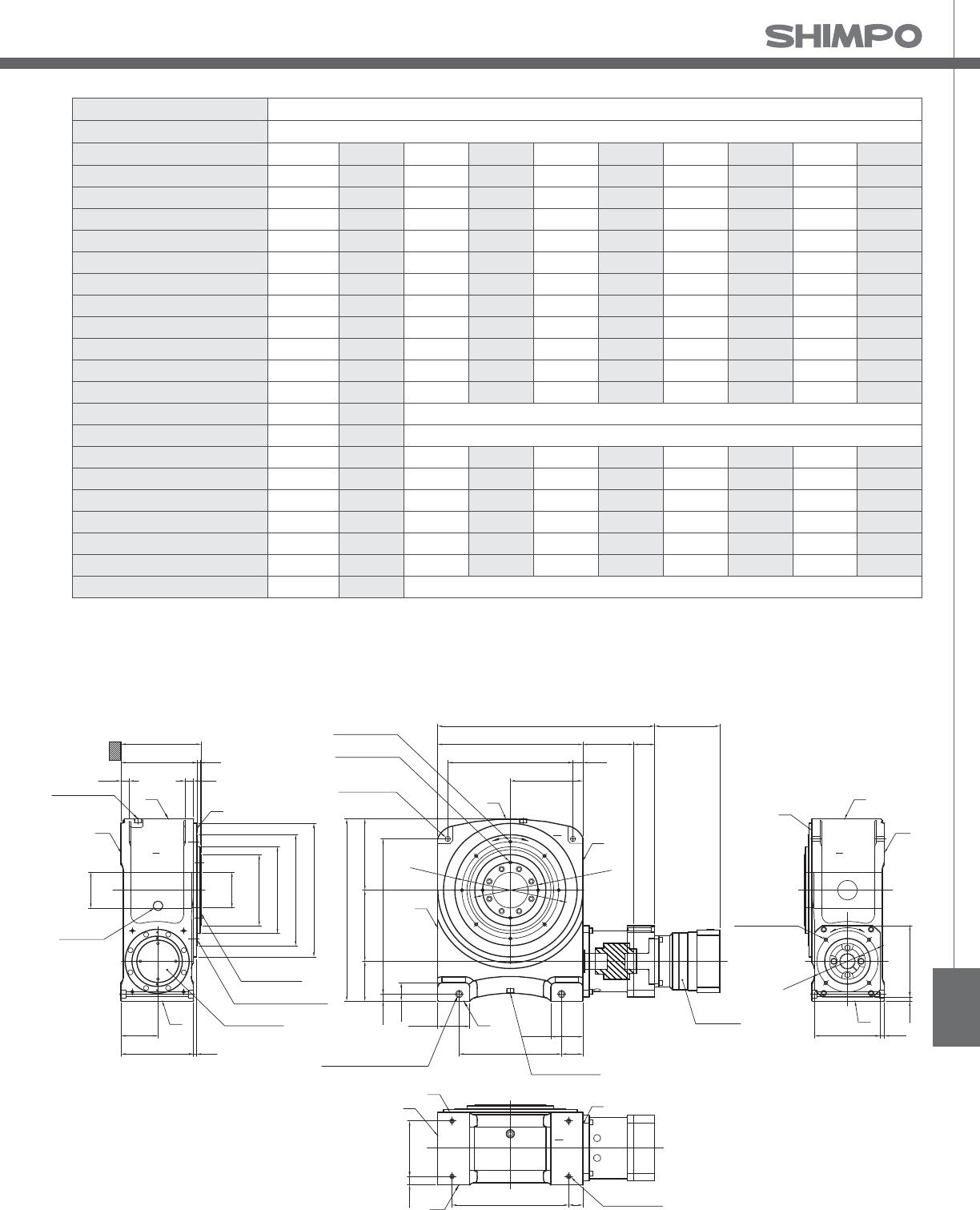
STR
Frame Size 250V
Stage 3-Stage
Ratio Units Notes 800 900 1000 1200 1400 1600 1800 2000
Nominal Torque [Nm] *1 4006 4006 4006 4006 4006 4006 4006 4006
Acceleration Torque [Nm] -- 6072 6072 6072 6072 6072 6072 6072 6072
No Load Torque [Nm] *1 2.0 2.0 2.0 2.0 2.0 2.0 2.0 2.0
Nominal Input Speed [rpm] *2 1500 1500 1500 1500 1500 1500 1500 1500
Maximum Input Speed [rpm] *2 3000 3000 3000 3000 3000 3000 3000 3000
Re ected Inertia (Single) [kg-mx10]*3 -- -- -- -- -- -- -- --
Re ected Inertia (≤Ø 28) [kg-mx10]*3 4.275 5.075 4.175 4.175 4.175 4.175 4.175 4.175
Re ected Inertia (≤Ø 38) [kg-mx10]*3 12.08 13.08 12.08 12.08 12.08 12.08 12.08 12.08
Re ected Inertia (≤Ø 48) [kg-mx10]*3 34.08 35.08 34.08 34.08 34.08 34.08 34.08 34.08
Re ected Inertia (≤Ø 65) [kg-mx10]*3 -- -- -- -- -- -- -- --
Backlash [arc-min] -- 0 0 0 0 0 0 0 0
Angular Transmission Accuracy [arc-min] -- ≤ 1.5
Angular Repeatability Accuracy [arc-min] -- ± 0.15
Surface Runout [µm (max)] -- 20 20 20 20 20 20 20 20
Weight [kg] -- 420 420 420 420 420 420 420 420
Maximum Axial Load [N] -- 38051 38051 38051 38051 38051 38051 38051 38051
Maximum Radial Load [N] -- 11165 11165 11165 11165 11165 11165 11165 11165
Maximum Tilting Moment Load [Nm] -- 2478.6 2478.6 2478.6 2478.6 2478.6 2478.6 2478.6 2478.6
E ciency [%] -- 72 72 72 72 72 72 72 72
Protection Class -- *4 IP54 (IP65)
STR-V 3-Stage Specifications with VRB-
*1) At nominal input speed
*2) Speeds are at the actuator input. Limits when used with additional gearbox are higher
*3) At input shaft
*4) IP65 (wash-down) is available as an option. Contact NIDECSHIMPO for more details and our food grade options
S
V
W
R
FIXED FLANGE
OUTPUT TABLE SURFACE
INPUT FLANGE
OIL LEVEL
OIL DRAIN PLUG
Rc3/4
GL
Ø127
Ø125
Depth 33
Ø250
Ø305h7
Ø390
Ø470h7
281
268 10
3030
640
65
112.5
25
140 250 250
545
762
440
255
178510
35
74
360 75
112.5
OIL FILLER PLUG
Rc3/4
Ø340
Ø195
S
T
R
**
19530
410 50 4-M16 Depth32
T
U
V
W
(SURFACE V&W)
255 10
130
2-18 DRILL
Counterbore 26 Depth 17.5
2-M20 Depth 30
S
V
W
R
4-M12 Depth24
**VRB-180
8-M12 Depth24
4-M12 Depth24
2-18 DRILL
2-M20 THRU
(SURFACE V&W)
R
V
U
T
d
c
230 15
25015
Ø215
a
b
U
STR- Dimensions with VRB-
NOTE:
** Refer to page , for VRB- dimensions
*** Optional
ROTATION:
a=d
a=c (upon special request)

STR-SERIES Rotary indexer
STR-E 1-Stage and 2-Stage Specifications with EVB-
Frame Size 250E
Stage 1-Stage 2-Stage
Ratio Units Notes 20 60 80 100 120 140 160 180
Nominal Torque [Nm] *1 4006 4006 4006 4006 4006 4006 4006 4006
Acceleration Torque [Nm] -- 6072 6072 6072 6072 6072 6072 6072 6072
No Load Torque [Nm] *1 14.5 11.5 11.5 11.5 11.5 11.5 11.5 11.5
Nominal Input Speed [rpm] *2 400 1500 1500 1500 1500 1500 1500 1500
Maximum Input Speed [rpm] *2 800 3000 3000 3000 3000 3000 3000 3000
Re ected Inertia (Single) [kg-mx10]*3 430.041 -- -- -- -- -- -- --
Re ected Inertia (≤Ø 14) [kg-mx10]*3 -- -- -- -- -- -- -- --
Re ected Inertia (≤Ø 19) [kg-mx10]*3 -- 94.785 78.795 72.965 69.815 67.505 66.345 65.675
Re ected Inertia (≤Ø 28) [kg-mx10]*3 -- 129.675 113.675 107.875 104.675 102.375 101.175 100.535
Re ected Inertia (≤Ø 38) [kg-mx10]*3 -- 215.275 199.275 193.475 190.275 187.975 186.775 186.175
Backlash [arc-min] -- 0 0 0 0 0 0 0 0
Angular Transmission Accuracy [arc-min] -- ≤ 1.5 ≤ 1.5
Angular Repeatability Accuracy [arc-min] -- ± 0.15 ± 0.15
Surface Runout [µm (max)] -- 20 20 20 20 20 20 20 20
Weight [kg] -- 383 432 432 432 432 432 432 432
Maximum Axial Load [N] -- 38051 38051 38051 38051 38051 38051 38051 38051
Maximum Radial Load [N] -- 11165 11165 11165 11165 11165 11165 11165 11165
Maximum Tilting Moment Load [Nm] -- 2478.6 2478.6 2478.6 2478.6 2478.6 2478.6 2478.6 2478.6
E ciency [%] -- 80 72 72 72 72 72 72 72
Protection Class -- *4 IP54 (IP65)
Frame Size 250E
Stage 2-Stage 3-Stage
Ratio Units Notes 200 300 320 400 500 560 600 700
Nominal Torque [Nm] *1 4006 4006 4006 4006 4006 4006 4006 4006
Acceleration Torque [Nm] -- 6072 6072 6072 6072 6072 6072 6072 6072
No Load Torque [Nm] *1 11.5 5.4 5.4 5.4 5.4 5.4 5.4 5.4
Nominal Input Speed [rpm] *2 1500 1500 1500 1500 1500 1500 1500 1500
Maximum Input Speed [rpm] *2 3000 3000 3000 3000 3000 3000 3000 3000
Re ected Inertia (Single) [kg-mx10]*3 -- -- -- -- -- -- -- --
Re ected Inertia (≤Ø 14) [kg-mx10]*3 -- 12.565 13.165 12.225 12.055 12.665 11.405 11.905
Re ected Inertia (≤Ø 19) [kg-mx10]*3 65.355 21.355 21.955 21.015 20.845 21.455 20.185 20.695
Re ected Inertia (≤Ø 28) [kg-mx10]*3 100.215 26.175 26.775 25.835 25.665 26.275 25.015 25.515
Re ected Inertia (≤Ø 38) [kg-mx10]*3 185.775 -- -- -- -- -- -- --
Backlash [arc-min] -- 0 0 0 0 0 0 0 0
Angular Transmission Accuracy [arc-min] -- ≤ 1.5 ≤ 1.5
Angular Repeatability Accuracy [arc-min] -- ± 0.15 ± 0.15
Surface Runout [µm (max)] -- 20 20 20 20 20 20 20 20
Weight [kg] -- 432 419 419 419 419 419 419 419
Maximum Axial Load [N] -- 38051 38051 38051 38051 38051 38051 38051 38051
Maximum Radial Load [N] -- 11165 11165 11165 11165 11165 11165 11165 11165
Maximum Tilting Moment Load [Nm] -- 2478.6 2478.6 2478.6 2478.6 2478.6 2478.6 2478.6 2478.6
E ciency [%] -- 72 68 68 68 68 68 68 68
Protection Class -- *4 IP54 (IP65)
STR-E 2-Stage and 3-Stage Specifications with EVB-
*1) At nominal input speed
*2) Speeds are at the actuator input. Limits when used with additional gearbox are higher
*3) At input shaft
*4) IP65 (wash-down) is available as an option. Contact NIDECSHIMPO for more details and our food grade options
*1) At nominal input speed
*2) Speeds are at the actuator input. Limits when used with additional gearbox are higher
*3) At input shaft
*4) IP65 (wash-down) is available as an option. Contact NIDECSHIMPO for more details and our food grade options

STR
Frame Size 250E
Stage 3-Stage
Ratio Units Notes 800 900 1000 1200 1400 1600 1800 2000
Nominal Torque [Nm] *1 4006 4006 4006 4006 4006 4006 4006 4006
Acceleration Torque [Nm] -- 6072 6072 6072 6072 6072 6072 6072 6072
No Load Torque [Nm] *1 5.4 5.4 5.4 5.4 5.4 5.4 5.4 5.4
Nominal Input Speed [rpm] *2 1500 1500 1500 1500 1500 1500 1500 1500
Maximum Input Speed [rpm] *2 3000 3000 3000 3000 3000 3000 3000 3000
Re ected Inertia (Single) [kg-mx10]*3 -- -- -- -- -- -- -- --
Re ected Inertia (≤Ø 14) [kg-mx10]*3 11.315 11.835 11.275 11.255 11.235 11.225 11.225 11.215
Re ected Inertia (≤Ø 19) [kg-mx10]*3 20.105 20.625 20.065 20.035 20.025 20.015 20.005 20.005
Re ected Inertia (≤Ø 28) [kg-mx10]*3 24.925 25.445 24.885 24.855 24.845 24.835 24.825 24.825
Re ected Inertia (≤Ø 38) [kg-mx10]*3 -- -- -- -- -- -- -- --
Backlash [arc-min] -- 0 0 0 0 0 0 0 0
Angular Transmission Accuracy [arc-min] -- ≤ 1.5
Angular Repeatability Accuracy [arc-min] -- ± 0.15
Surface Runout [µm (max)] -- 20 20 20 20 20 20 20 20
Weight [kg] -- 419 419 419 419 419 419 419 419
Maximum Axial Load [N] -- 38051 38051 38051 38051 38051 38051 38051 38051
Maximum Radial Load [N] -- 11165 11165 11165 11165 11165 11165 11165 11165
Maximum Tilting Moment Load [Nm] -- 2478.6 2478.6 2478.6 2478.6 2478.6 2478.6 2478.6 2478.6
E ciency [%] -- 68 68 68 68 68 68 68 68
Protection Class -- *4 IP54 (IP65)
STR-E 3-Stage Specifications with EVB-
*1) At nominal input speed
*2) Speeds are at the actuator input. Limits when used with additional gearbox are higher
*3) At input shaft
*4) IP65 (wash-down) is available as an option. Contact NIDECSHIMPO for more details and our food grade options
STR- Dimensions with EVB-
S
V
W
R
FIXED FLANGE
OUTPUT TABLE SURFACE
INPUT FLANGE
OIL LEVEL
OIL DRAIN PLUG
GL
Ø127
Ø125
Depth 33
Ø250
Ø305h7
Ø390
Ø470h7
281
268 10
3030
640
65
112.5
25
140 250 250
545
762
440
255
178510
35
74
360 75
112.5
Rc3/4
Ø340
Ø195
S
T
R
**
19530
410 50 4-M16 Depth32
T
U
V
W
(SURFACE V&W)
255 10
130
2-18 DRILL
Counterbore 26 Depth 17.5
2-M20 Depth 30
S
V
W
R
230 15
25015
Ø215
4-M12 Depth24
8-M12 Depth24
4-M12 Depth24
2-18 DRILL
2-M20 THRU
(SURFACE V&W)
V
U
T
d
c
Rc3/4
OIL FILLER PLUG
**EVB-180
a
b
R
**
U
NOTE:
** Refer to page , for EVB- dimensions
*** Optional
ROTATION:
a=d
a=c (upon special request)

High reduction ratios, without sacrificing efficiency. Com-
pact designs, without requiring special motors. Exceptional
shock load capacity, without having to oversize. Greater over-
hung load capacities, without using expensive special compo-
nents. The (Servo ER) Circulute is ideal for those applications in
heavier industrial environments where a more robust cycloidal
gearbox is necessary.
The dual pin-housing of the cycloidal provides the ability to pre-
load one wheel against the other reducing the output shaft back-
lash to less than arc-min. The long output shaft bearing span pro-
vides exceptional overhung load capabilities. At , rpm input
the (Servo ER) Circulute can handle motors up to kW and single
reduction ratios ranging from : to :.
ER-SERIES

ER-SERIES
■High e ciency cycloidal reducer design
■Multiple inputs: NEMA C-Face, Servo Square Flange, Shaft Input,
Shovel Base, Top Mount
■Straddle mount output shaft bearings (sizes D, E, F)
■Multiple mounting options: Base, ange, ring
■Readily available
■Assembled in the USA
ER

ER-SERIES Circulute cycloidal reducer
ER-Series Features
2
1 Output shaft bearings
2 Output shaft
3 Internal pin housing
4 Internal pin
5 Wheels
6 Carrier pins
7 Input shaft
8 Eccentric roller bearings
9 Various mounting options
8
7
4
3
9
6
5
1

ER
ER-Series Model Code
Backlash
Quill Shaft Diameter
Quill Shaft Tolerance
(Specied by Shimpo)
(See Dimensional Table)
Mounting
Type Position
Modications
(Use dashes for any place
not used - list modications
in alphabetical order
using position one rst)
Servo Motor Bolt Circle Diameter (mm)
Backlash
Servo Motor Input
Reduction Ratio (From the selection tables use dashes if all four places are not used)
Frame size (From the selection tables)
0B−− −−771S009016ABH
*1) Standard Backlash: Approximately 60 arc-min - 0
*2) Precision Backlash: Less than 6 arc-min - P
Contact us for additional information or refer to our online reducer selection tool.
Selection tool www.nidec-shimpo.co.jp/selection/eng

ER-SERIES Circulute cycloidal reducer
Rating Table - rpm Input, Single Reduction, Precision Backlash (less than arc-min)
*1) The reducer can continuously sustain this torque value without overheating
*2) The reducer can sustain this torque value for cycles without failure
*3) Acceleration torque is . times the nominal output torque
Frame Size Ratio Units Notes 11 17 29 35 47 59 71
B03
Input [kW] -- 1.430 1.160 0.710 0.560 0.390 0.320 0.250
Nominal Output Torque [Nm] *1 45.000 56.300 59.200 56.600 52.800 54.000 51.400
Emergency Stopping Torque [Nm] *2 112 141 148 141 132 135 128
Torsional Rigidity [Nm/arc-min] -- 3.000 4.700 5.000 5.400 5.400 5.400 5.400
Moment of Inertia [kg-cm] -- 0.716 0.969 0.927 0.927 0.927 0.927 0.927
B07
Input [kW] -- 1.900 1.540 0.950 0.750 0.520 0.430 0.340
Nominal Output Torque [Nm] *1 60.000 75.000 78.900 75.400 78.200 79.900 76.100
Emergency Stopping Torque [Nm] *2 150 188 197 189 196 200 190
Torsional Rigidity [Nm/arc-min] -- 3.000 4.700 5.000 5.400 5.400 5.400 5.400
Moment of Inertia [kg-cm] -- 0.716 0.969 0.927 0.927 0.927 0.927 0.927
C03
Input [kW] -- 2.910 2.690 1.690 1.550 1.080 0.860 0.710
Nominal Output Torque [Nm] *1 91.700 131 140 155 145 145 144
Emergency Stopping Torque [Nm] *2 229 328 350 388 362 362 361
Torsional Rigidity [Nm/arc-min] -- 6.200 11.200 11.900 12.600 12.600 12.600 12.600
Moment of Inertia [kg-cm] -- 3.118 3.412 4.171 4.129 4.086 4.086 4.086
C07
Input [kW] -- 3.880 3.590 2.250 2.060 1.430 1.140 0.950
Nominal Output Torque [Nm] *1 122 175 187 207 214 214 214
Emergency Stopping Torque [Nm] *2 306 437 467 517 536 536 535
Torsional Rigidity [Nm/arc-min] -- 6.200 11.200 11.900 12.600 12.600 12.600 12.600
Moment of Inertia [kg-cm] -- 3.118 3.412 4.171 4.129 4.086 4.086 4.086
D03
Input [kW] -- 6.830 5.380 3.400 3.010 2.240 1.720 1.360
Nominal Output Torque [Nm] *1 215 262 282 302 302 290 277
Emergency Stopping Torque [Nm] *2 538 654 705 754 754 725 693
Torsional Rigidity [Nm/arc-min] -- 17.800 23.000 25.200 27.400 27.400 27.400 27.400
Moment of Inertia [kg-cm] -- 7.752 10.996 12.007 11.754 11.754 11.754 11.501
D07
Input [kW] -- 9.110 7.170 4.530 4.010 2.990 2.290 1.820
Nominal Output Torque [Nm] *1 287 349 376 402 447 430 411
Emergency Stopping Torque [Nm] *2 718 872 940 1,010 1,120 1,070 1,030
Torsional Rigidity [Nm/arc-min] -- 17.800 23.000 25.200 27.400 27.400 27.400 27.400
Moment of Inertia [kg-cm] -- 7.752 10.996 12.007 11.754 11.754 11.754 11.501

ER
Rating Table - rpm Input, Single Reduction, Precision Backlash (less than arc-min)
*1) The reducer can continuously sustain this torque value without overheating
*2) The reducer can sustain this torque value for cycles without failure
*3) Acceleration torque is . times the nominal output torque
Frame Size Ratio Units Notes 11 17 29 35 47 59 71
E03
Input [kW] -- 13.100 11.600 9.710 8.050 5.390 4.430 3.420
Nominal Output Torque [Nm] *1 618 849 1,210 1,210 1,090 1,120 1,040
Emergency Stopping Torque [Nm] *2 1,540 2,120 3,030 3,030 2,730 2,800 2,600
Torsional Rigidity [Nm/arc-min] -- 54.800 70.400 85.200 85.200 85.200 85.200 85.200
Moment of Inertia [kg-cm] -- 31.512 52.661 49.291 48.869 48.448 48.448 48.027
E07
Input [kW] -- 17.400 15.500 13.000 10.700 7.190 5.910 4.570
Nominal Output Torque [Nm] *1 824 1,130 1,610 1,610 1,450 1,500 1,390
Emergency Stopping Torque [Nm] *2 2,060 2,660 3,520 3,520 3,520 3,520 3,480
Torsional Rigidity [Nm/arc-min] -- 54.800 70.400 85.200 85.200 85.200 85.200 85.200
Moment of Inertia [kg-cm] -- 31.512 52.661 49.291 48.869 48.448 48.448 48.027
F03
Input [kW] -- 20.200 19.900 17.000 14.800 10.800 8.170 6.790
Nominal Output Torque [Nm] *1 953 1,450 2,120 2,230 2,180 2,070 2,070
Emergency Stopping Torque [Nm] *2 2,380 3,630 5,300 5,580 5,450 5,180 5,180
Torsional Rigidity [Nm/arc-min] -- 116.700 122.300 133.400 133.400 133.400 133.400 133.400
Moment of Inertia [kg-cm] -- 87.628 74.989 130.178 127.650 127.650 127.650 125.122
F07
Input [kW] -- 26.900 26.500 22.600 19.800 14.400 10.900 9.060
Nominal Output Torque [Nm] *1 1,270 1,940 2,820 2,970 2,900 2,760 2,760
Emergency Stopping Torque [Nm] *2 3,180 4,850 7,050 7,350 7,350 6,900 6,900
Torsional Rigidity [Nm/arc-min] -- 116.700 122.300 133.400 133.400 133.400 133.400 133.400
Moment of Inertia [kg-cm] -- 87.628 74.989 130.178 127.650 127.650 127.650 125.122

ER-SERIES Circulute cycloidal reducer
ER Common Dimensions Single Stage Base Mount
*1) Sizes A through B do not have a lifting eye
T
L
Key
U
R
V
BA
F1
F
ØDF
Motor
Mounting
Flange
B
4-H
E
A
D
G
P
W
Frame Size Units A B BA D DF E F F1 G H P
A03 - A07 [mm] 175.01 119.89 65.28 89.99 N/A 145.03 89.92 14.99 16.00 11.94 147.07
A190 - A195 [mm] 180.09 134.87 59.94 100.00 N/A 150.11 89.92 14.99 11.94 10.92 147.07
B01 - B07 [mm] 175.01 150.11 85.85 115.01 N/A 145.03 119.89 14.99 16.00 11.94 150.11
B195 - B105 [mm] 180.09 134.87 59.94 100.00 N/A 150.11 89.92 14.99 11.94 10.92 150.11
B20H [mm] 180.09 134.87 59.94 119.99 N/A 150.11 89.92 14.99 11.94 10.92 150.11
C01 - C07 [mm] 219.96 189.99 103.38 140.00 N/A 180.09 150.11 20.07 22.10 14.99 189.99
C110 - C115 [mm] 230.12 154.94 82.04 119.99 N/A 189.99 115.06 20.07 14.99 13.97 189.99
C225 [mm] 230.12 154.94 82.04 140.00 N/A 189.99 115.06 20.07 14.99 13.97 189.99
D01 - D07 [mm] 275.08 230.12 135.38 165.00 N/A 225.04 180.09 24.89 25.91 19.05 234.95
D135 [mm] 330.20 195.07 100.08 149.99 N/A 290.07 145.03 24.89 22.10 18.03 234.95
D145 [mm] 330.20 195.07 119.89 149.99 N/A 290.07 145.03 24.89 22.10 18.03 234.95
D225 [mm] 330.20 195.07 119.89 159.99 N/A 290.07 145.03 24.89 22.10 18.03 233.68
E01 - E07 [mm] 359.92 299.97 150.88 184.99 312.93 299.97 249.94 24.89 29.97 22.10 299.97
E165 [mm] 409.96 238.00 138.94 159.99 312.93 369.82 150.11 43.94 24.89 18.03 299.97
E370 - E375 [mm] 430.02 335.03 124.97 200.00 312.93 379.98 275.08 29.97 29.97 22.10 414.02
F03 - F07 [mm] 424.94 365.00 194.82 210.01 368.05 350.01 294.89 35.05 35.05 24.89 359.92

ER
ER Flange Dimensions Single Stage Base Mount
*1) Other servo anges and bore sizes are available.
Contact Shimpo Drives Customer Service for
additional information
*2) All dimensions are in mm, except for «R»
dimension, which is in inches
*3) To download CAD drawings, visit our website:
www.shimpodrives.com
*4) The "R" dimension is the length from input ange
face to output shaft end
Motor Mounting FlangeCircleSquare
Frame Size LC LD LF LG LH LN LJ MH ML R Net Weight
(kg)
A03 - A07
70 -- 5 5 50 120 M5 14, 16 37 202.692 9.98
90 -- 5 7 70 120 M6 16, 19 57 212.60 9.98
100 -- 7 7 80 120 M6 16, 19 -- 214.63 9.98
115 100 7 7 95 -- M6 19, 24 57 212.60 9.98
145 110 7 8 110 -- M8 22, 24 -- 212.60 12.70
B03 - B07
70 -- 5 5 50 120 M5 14, 16 37 238.00 16.33
90 -- 5 7 70 120 M6 16, 19 57 247.90 16.33
100 -- 7 7 80 120 M6 16, 19 -- 249.94 16.33
115 100 7 7 95 -- M6 19, 24 57 247.90 16.33
145 110 7 8 110 -- M8 22, 24 -- 247.90 17.23
C03 - C07
90 -- 7 7 70 160 M6 16 -- 293.88 30.84
100 -- 7 7 80 120 M6 16, 19 -- 300.99 30.84
115 130 7 7 95 -- M6 22, 24 -- 293.88 30.84
145 130 7 8 110 -- M8 24, 28 -- 293.88 30.84
200 176 7 7 114.3 -- M12 28, 35 -- 328.93 38.55
D03 - D07
115 -- 7 7 95 200 M6 22, 24 -- 354.08 52.15
145 130 8 8 110 -- M8 22, 24 -- 349.00 52.15
165 -- 8 8 130 200 M10 24, 28 -- 360.93 52.15
200 176 10 7 114.3 -- M12 28, 35 -- 378.97 56.69
215 -- 10 10 180 300 M12 35, 38 -- 399.03 61.22
E03 - E07
145 -- 10 7 110 250 M8 24, 28 -- 409.96 111.56
165 176 7 7 130 -- M12 24, 28 -- 399.03 101.59
200 176 7 6 114.3 -- M12 28, 35 -- 399.03 101.59
215 -- 10 11 180 300 M12 35, 38 -- 459.99 116.55
235 -- 8 11 200 350 M12 38, 42 -- 494.03 129.71
F03 - F07
200 -- 10 7 114.3 300 M12 28, 35 -- 546.10 207.71
215 -- 10 8 180 300 M12 35, 38 -- 546.10 207.71
235 -- 5 11 200 300 M12 38, 42 -- 546.10 207.71
265 -- 5 11 230 400 M12 42, 48 -- 564.90 219.50
MH AU AW ML
14 16 5 32
16 18 5 37
19 21.5 6 42
22 25 8 57
24 27 8 67
MH AU AW ML
28 31 8 67
35 38 10 67
38 41 10 88
42 45 12 118
48 51.5 14 118
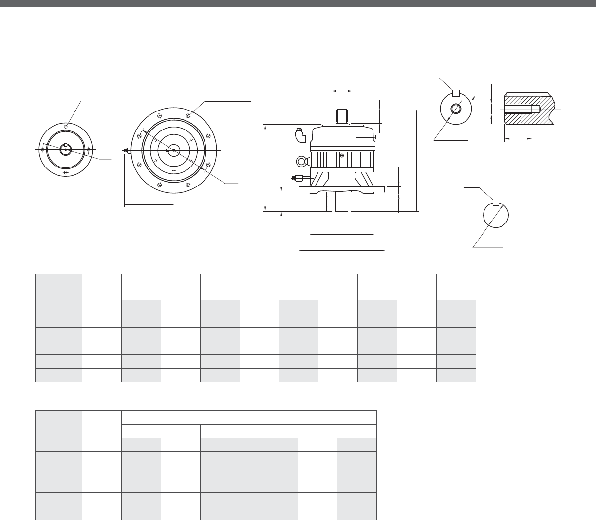
ER-SERIES Circulute cycloidal reducer
ER Common Dimensions Single Stage Flange Mount
HO
AG
C
BD
Ø
R
BB
BE
AM
Ø
AG
L
T
U
UA
Key
Key
BH
V
VA
DF
Ø
Motor
Mounting
Flange
Shaft
Input
Sizes D01-F07
Sizes A03-C07
BF Hole Diameter
BG Number of Holes
BF Hole Diameter
BG Number of Holes
Output Flange
Output Shaft
Input Shaft
Frame Size Units AG AM BB BD BE BF BG BH HO
A03 - A07 [mm] 130.05 110.01 4.06 160.02 13.97 11.94 101.60 29.97 N/A
B01 - B07 [mm] 165.10 130.00 4.06 199.90 13.97 11.94 101.60 40.13 N/A
C01 - C07 [mm] 214.88 180.01 4.06 249.94 18.03 14.99 101.60 55.12 N/A
D01 - D07 [mm] 264.92 230.00 5.08 299.97 22.10 14.99 203.20 70.10 184.91
E01 - E07 [mm] 350.01 300.00 7.87 400.05 24.89 19.05 203.20 89.92 230.12
F03 - F07 [mm] 400.05 350.01 7.87 450.09 24.89 19.05 203.20 109.98 260.10
Frame Size Units Output Shaft
UV Key T L
A03 - A07 [mm] 22.23 30.23 4.78x4.78x24.89 N/A N/A
B01 - B07 [mm] 34.925 50.80 7.95x7.95x44.96 N/A N/A
C01 - C07 [mm] 44.450 63.50 9.53x9.53x54.86 N/A N/A
D01 - D07 [mm] 63.500 95.25 15.88x15.88x74.93 M10 x 1.5 18.03
E01 - E07 [mm] 73.025 111.00 19.05x19.05x95.00 M20 x 2.5 35.05
F03 - F07 [mm] 92.075 139.70 22.23x22.23x115.06 M20 x 2.5 35.05

ER
ER Flange Dimensions Single Stage Flange Mount
ML
LG
LH
LF
(SQUARE)
4-LJ
LD
AW
LC
MH
AU
LH
LF
ML
LG
(CIRCLE)
4-LJ
AU
LC
MH
LN
AW
R
Motor
Mounting
Flange
*1) Other servo anges and bore sizes are available.
Contact Shimpo Drives Customer Service for
additional information
*2) All dimensions are in mm, except for «R»
dimension, which is in inches
*3) To download CAD drawings, visit our website:
www.shimpodrives.com
Frame Size LC LD LF LG LH LN LJ MH ML R Net Weight
(kg)
A03 - A07
70 -- 5 5 50 120 M5 14, 16 37 202.69 9.98
90 -- 5 7 70 120 M6 16, 19 57 212.60 9.98
100 -- 7 7 80 120 M6 16, 19 -- 214.63 9.98
115 100 7 7 95 -- M6 19, 24 57 212.60 9.98
145 110 7 8 110 -- M8 22, 24 -- 212.60 12.70
B03 - B07
70 -- 5 5 50 120 M5 14,16 37 238.00 16.33
90 -- 5 7 70 120 M6 16, 19 57 247.90 16.33
100 -- 7 7 80 120 M6 16, 19 -- 249.94 16.33
115 100 7 7 95 -- M6 19, 24 57 247.90 16.33
145 110 7 8 110 -- M8 22, 24 -- 247.90 17.23
C03 - C07
90 -- 7 7 70 160 M6 16 -- 293.88 30.84
100 -- 7 7 80 120 M6 16, 19 -- 300.99 30.84
115 130 7 7 95 -- M6 22, 24 -- 293.88 30.84
145 130 7 8 110 -- M8 24, 28 -- 293.88 30.84
200 176 7 7 114.3 -- M12 28, 35 -- 328.93 38.55
D03 - D07
115 -- 7 7 95 200 M6 22, 24 -- 354.08 52.15
145 130 8 8 110 -- M8 22, 24 -- 349.00 52.15
165 -- 8 8 130 200 M10 24, 28 -- 360.93 52.15
200 176 10 7 114.3 -- M12 28, 35 -- 378.97 56.69
215 -- 10 10 180 300 M12 35, 38 -- 399.03 61.22
E03 - E07
145 -- 10 7 110 250 M8 24, 28 -- 409.96 111.56
165 176 7 7 130 -- M12 24, 28 -- 399.03 101.59
200 176 7 6 114.3 -- M12 28, 35 -- 399.03 101.59
215 -- 10 11 180 300 M12 35, 38 -- 459.99 116.55
235 -- 8 11 200 350 M12 38, 42 -- 494.03 129.71
F03 - F07
200 -- 10 7 114.3 300 M12 28, 35 -- 546.10 207.71
215 -- 10 8 180 300 M12 35, 38 -- 546.10 207.71
235 -- 5 11 200 300 M12 38, 42 -- 546.10 207.71
265 -- 5 11 230 400 M12 42, 48 -- 564.90 219.50
MH AU AW ML
14 16 5 32
16 18 5 37
19 21.5 6 42
22 25 8 57
24 27 8 67
MH AU AW ML
28 31 8 67
35 38 10 67
38 41 10 88
42 45 12 118
48 51.5 14 118

Technical Information
Installation Instructions ...............................
Safety Precautions ....................................
Adapter Flange Codes............................. -
Selection Flow Charts ............................. -
Online Sizing and Selection Tool ................... -


Mounting Procedure to Motor
1. Wipe o anti-rust agent and oil on the motor shaft.
2. Remove the plug.
5. Tighten the clamping bolt of the input shaft with torque
wrench to the proper torque. (See table )
6. Reinstall the plug. The procedure is complete.
Reducer Installation
After con rming the installation surface is at and clean, tighten
the bolt using a torque wrench to the proper torque. (See table )
* Recommended bolt: Strength .
Table 2
Bolt Size Tightening Torque
Table 1
Motor Installing Bolts Clamping Bolts
Bolt Size
----
3. Turn the input shaft until the cap screw is seen. Make sure
the cap screw is loosened. Place reducer vertically on the
at surface so the motor mounting part faces up.
NOTE: In case the bushing has been attached, see reducer
drawing example below to x.
4. Carefully and gently insert the motor shaft into the input
shaft. Make sure the motor ange is perfectly t to the
reducer’s ange. Tighten the motor by installing and
tightening bolts to the proper torque. (See table )
Installation Instructions

Cautions for Operation
■ When the reducer is delivered to you, con rm that you received the exact model that you ordered.
Please wipe out the input and output shaft of the reducer which is covered by anti-corrosive oil.
* Remove rubber cap on the input shaft before you wipe the shafts.
* Lubricant (grease) is already lled in the reducer. The reducer is ready for operation out of the box.
Fixation and Installation
■ Avoid use in places where rain or water drops directly, unless special wash down design.
▪ In case of use outdoors or in a places where dust and water drops directly, consult SHIMPO in advance.
■ Install at °~°C of surrounding temperature.
▪ In case of use at temperature out of the mentioned (°~°C) range, consult SHIMPO in advance.
■ Firmly x with a bolt onto a solid stand without vibration.
■ Install in a convenient location for future repair and inspection.
Cautions Prior to Starting the Operation
■ Reducer can be used on arrival, since it has already been lled with lubrication.
■ At initial operation, check the rotating direction of the output shaft and then gradually apply load.
Cautions During Operation
■ Avoid overload.
■ Ensure that input speed shall not exceed the number of maximum revolutions per minute speci ed.
■ In the event the following occurs, stop the operation and check the following points:
▪ If temperature sharply increases
▪ If an abnormal noise appears sharply
▪ If the number of revolutions becomes unstable sharply
■ In the event the following occurs, respond immediately to the issue or contact us as soon as possible.
▪ Is it under overload condition?
▪ Is lubricant insu cient or deteriorated, or was another lubricant applied?
▪ Is the axis, gear, and/or motor input damaged?
▪ Are any connections unstable?
Disassembly
■ ABLE REDUCER is designed to not be disassembled.
Lubricant Use
■ The ABLE REDUCER is of grease-seal type in all models.
A speci ed amount of grease is lled at factory release so you can use as soon as it is delivered to you.
■ It is impossible to exchange grease.
■ In case of use outside of the recommended temperature range, consult SHIMPO in advance.
Daily Check Points
■ Is the reducer case temperature excessively high during operation? (Up to + °C is not signi cant.)
■ Is there an abnormal noise in the bearing, gear, etc?
■ Is there an abnormal vibration in the reducer?
* Upon an abnormal phenomenon, immediately stop the operation and contact us.
■ Is there a lubricant leak?
Periodic Check Points
■ Are there overload and abnormal rotation?
■ Are free, sprocket, and reducer assembling bolts loose?
■ Is there an abnormal condition in the electric system?
■ Checkup and repair of major parts
* Upon an abnormal condition, immediately stop the operation and contact us.
■ Oil leak
* Upon an oil leak, contact us.
Scrapping
Whenever scrapping the ABLE REDUCER, classify the parts by material into industrial wastes as speci ed in the laws and regulations of your
local government. Materials of construction can be divided into the following four categories:
1. Rubber parts: Oil seal, seat packing, rubber cap, seal used for bearing on the motor ange, etc.
2. Aluminum parts: Motor ange, output shaft holder
3. Grease: Wipe o the grease from the individual parts with dry cloth and scrap into oils.
4. Iron parts: Parts other than those mentioned in the above
Safety Precaution

Adapter Flange Codes
Adapter Flange Codes
These tables provide an explanation for the adapter codes. The tables start with Input Bore measurement and the Part # Code, which
are indicated at the end of every model code. For each Part # Code, the Pilot, PCD, Tapped Hole, and Pilot Depth, are explained.
Please note that even though the Part# Code may have the same letters (i.e. DC, FB, HA, etc), the Pilot and PCD dimensions may
not be the same if a di erent input bore diameter. Locate the table by input bore diameter rst, and then nd the appropriate
adapter Part# Code to check the dimensions. If you have any questions, contact NIDECSHIMPO for support.
Input Bore
(mm)
Part#
Code
Pilot
(mm)
PCD
(mm)
Tapped
Hole
Pilot
Depth
(mm)
65 MA 114.3 200 M12 8
65 MB 200 235 M12 8
65 MC 180 215 M12 8
65 MD 180 265 M12 8
65 NA 230 265 M12 8
65 NB 230 265 M12 18
65 NC 230 290 M12 8
65 ND 230 265 M20 18
65 PA 250 300 M16 8
65 PB 250 320 M16 18
65 QA 300 350 M16 8
65 QB 280 325 M16 8
Input Bore
(mm)
Part#
Code
Pilot
(mm)
PCD
(mm)
Tapped
Hole
Pilot
Depth
(mm)
48 KA 114.3 200 M12 8
48 KB 110 130 8.8 8
48 KC 130 215 M12 8
48 LA 180 215 M12 8
48 MA 180 265 M12 8
48 MB 200 235 M12 8
48 NA 230 265 M12 8
48 PA 250 300 M16 8
Input Bore
(mm)
Part#
Code
Pilot
(mm)
PCD
(mm)
Tapped
Hole
Pilot
Depth
(mm)
38 HA 110 130 8.8 8
38 HB 110 145 M8 8
38 HE 110 130 M8 8
38 JA 130 165 M10 8
38 KA 114.3 200 M12 8
38 KB 130 215 M10 8
38 KC 130 215 M12 8
38 KD 95 200 M10 18
38 KE 114.3 200 M12 18
38 LA 180 215 M12 8
38 LB 180 215 M12 18
38 MA 180 265 M12 8
38 MB 200 235 M12 8
38 MC 215.9 184.15 13.7 5.5
38 MD 200 250 M8 18
38 NA 230 265 M12 8
PILOT DEPTH
INPUT SHAFT
PILOT
TAPPED HOLE
ADAPTER FLANGE
PCD
INPUT BORE

Adapter Flange Codes
Input Bore
(mm)
Part#
Code
Pilot
(mm)
PCD
(mm)
Tapped
Hole
Pilot
Depth
(mm)
28 FA 80 100 M6 8
28 FB 95 115 M6 8
28 FC 95 115 M8 8
28 FD 95 115 M6 8
28 FE 95 115 M8 8
28 GA 55.563 125.73 M6 8
28 GB 63.5 127 M6 8
28 GC 95 130 M8 8
28 GD 110 130 M8 8
28 GE 110 130 M10 8
28 GF 110 130 8.8 8
28 GG 110 135 M8 8
28 GH 95 135 M8 8
28 HA 110 145 M8 8
28 HB 110 145 M8 18
28 HC 110 145 10.5 8
28 HD 114.3 149.23 10.5 8
28 HE 95 145 M8 18
28 HF 110 145 M8 8
28 JA 110 165 M8 8
28 JB 110 165 M10 8
28 JC 130 165 M10 8
28 JD 130 174 M10 28
28 JE 130 165 M10 18
28 JF 114.3 160 M10 8
28 KA 114.3 200 M12 8
28 KB 130 215 M10 8
28 KD 114.3 200 M12 18
28 KE 150 185 M10 8
28 LA 180 215 M12 8
28 LB 180 220 M12 18
28 MA 200 235 M12 8
28 MB 200 250 M8 18
Input Bore
(mm)
Part#
Code
Pilot
(mm)
PCD
(mm)
Tapped
Hole
Pilot
Depth
(mm)
19 DA 60 90 M5 6
19 DB 70 90 M5 6
19 DC 70 90 M6 6
19 DD 70 90 M6 16
19 DE 70 90 M5 11
19 EA 73.025 98.43 M5 11
19 EB 80 100 M6 6
19 EC 80 100 M6 16
19 ED 60 98.99 M6 6
19 FA 95 115 M8 6
19 FB 95 115 M8 16
19 GA 55.563 125.73 M6 11
19 GB 95 130 M8 6
19 GC 110 130 M8 11
19 GD 110 130 8.8 6
19 GE 95 130 M8 16
19 GF 100 125 M8 16
19 GH 95 135 M8 11
19 HA 110 145 M8 6
19 HB 110 145 M8 21
19 HC 110 145 10.5 11
19 HD 114.3 149.23 M8 11
19 HE 114.3 149.23 10.5 11
19 JA 130 165 M10 16
19 JB 115 165 M8 21
PILOT DEPTH
INPUT SHAFT
PILOT
TAPPED HOLE
ADAPTER FLANGE
PCD
INPUT BORE
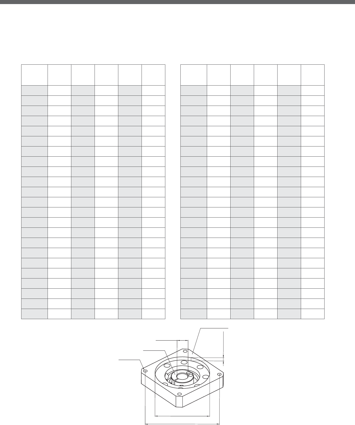
Adapter Flange Codes
PILOT DEPTH
INPUT SHAFT
PILOT
TAPPED HOLE
ADAPTER FLANGE
PCD
INPUT BORE
Input Bore
(mm)
Part#
Code
Pilot
(mm)
PCD
(mm)
Tapped
Hole
Pilot
Depth
(mm)
14 BA 38.1 66.68 M4 5
14 BB 38.1 66.68 M5 5
14 BC 38.1 66.68 M5 10
14 BD 40 63 M4 5
14 BE 40 63 M5 5
14 BF 40 65 M5 5
14 BG 40 70 M4 5
14 BH 50 60 M4 10
14 BJ 50 70 M4 5
14 BK 50 70 M5 5
14 BL 50 70 M5 15
14 BM 50 70 M5 10
14 BN 50 70 M4 10
14 BP 36 70.71 M4 5
14 CA 60 75 M5 5
14 CB 60 75 M6 10
14 CC 60 80 M4 5
14 DA 50 95 M6 5
14 DB 60 85 M5 5
14 DC 60 90 M5 5
14 DD 70 85 6.5 5
14 DE 70 90 M5 10
14 DF 70 90 M6 5
Input Bore
(mm)
Part#
Code
Pilot
(mm)
PCD
(mm)
Tapped
Hole
Pilot
Depth
(mm)
14 DG 70 90 M6 15
14 DH 70 95 M6 5
14 DJ 60 95 M5 5
14 DK 36.8 82.024 M6 15
14 DL 62 91.924 M5 10
14 EA 50 100 M6 5
14 EB 73.025 98.43 M5 5
14 EC 80 100 M6 5
14 ED 80 100 M6 15
14 EE 73.025 98.43 M6 15
14 EF 50 98.43 M5 5
14 EG 60 98.995 M5 5
14 EH 80 105 M6 15
14 EJ 60 98.995 M6 10
14 EK 73.025 98.43 M6 5
14 EL 73 94 M6 5
14 EM 83 104 M8 10
14 FA 60 115 M6 5
14 FB 95 115 M8 15
14 GA 80 139.7 M6 5
14 GB 80 130 M5 20
14 GC 94 120 M8 10
14 JA 115 165 M8 10
Adapter Flange Codes
These tables provide an explanation for the adapter codes. The tables start with Input Bore measurement and the Part # Code, which
are indicated at the end of every model code. For each Part # Code, the Pilot, PCD, Tapped Hole, and Pilot Depth, are explained.
Please note that even though the Part# Code may have the same letters (i.e. DC, FB, HA, etc), the Pilot and PCD dimensions may
not be the same if a di erent input bore diameter. Locate the table by input bore diameter rst, and then nd the appropriate
adapter Part# Code to check the dimensions. If you have any questions, contact NIDECSHIMPO for support.
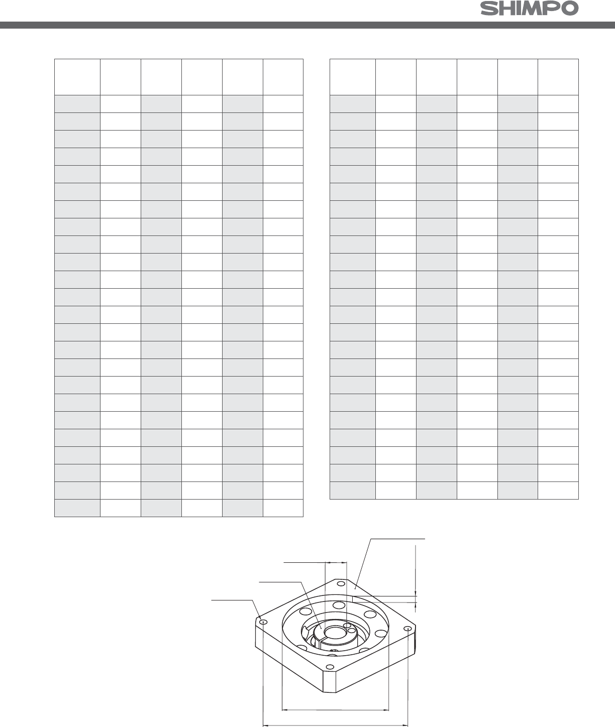
Input Bore
(mm)
Part#
Code
Pilot
(mm)
PCD
(mm)
Tapped
Hole
Pilot
Depth
(mm)
8 AA 20.02 46.69 M3 5
8 AB 22 43.82 4.7 10
8AC2248M35
8 AD 22.22 50.8 M3 5
8 AE 25.4 38.89 4 10
8AF3045M35
8AG3046M45
8 AH30 46M410
8 AJ 30 46 3.5 10
8 AK34 48M310
8AL3048M35
8 AM 22 43.82 3.5 5
8AN4050M45
8 AQ 37.6 48 M3 5
8 BA 38.1 66.68 M4 5
8 BB 38.1 66.68 M5 5
8 BC 50 60M410
8BD5070M45
8BE5070M55
8 BF 50 70M510
8 BG 36 70.71 M4 5
8BH5470M45
8BJ5058M35
8 CA50 80M410
Input Bore
(mm)
Part#
Code
Pilot
(mm)
PCD
(mm)
Tapped
Hole
Pilot
Depth
(mm)
S8 ZA 20.02 46.69 M3 5
S8 ZB 22 43.82 4.7 10
S8 ZC 22 48 M3 5
S8 ZD 22.22 50.8 M3 5
S8 ZE 25.4 38.89 4 10
S8 ZF 30 45 M3 5
S8 ZG 30 46 M4 5
S8 ZH 30 46 M4 10
S8 ZJ 30 46 3.5 10
S8 ZK 34 48 M3 10
S8 ZL 30 48 M3 5
S8 ZM 22 43.82 3.5 5
S8 ZN 40 50 M4 5
S8 ZQ 37.6 48 M3 5
S8 BA 38.1 66.68 M4 5
S8 BB 38.1 66.68 M5 5
S8 BC 50 60 M4 10
S8 BD 50 70 M4 5
S8 BE 50 70 M5 5
S8 BF 50 70 M5 10
S8 BG 36 70.71 M4 5
S8 BH 54 70 M4 5
S8 BJ 50 58 M3 5
Adapter Flange Codes
PILOT DEPTH
INPUT SHAFT
PILOT
TAPPED HOLE
ADAPTER FLANGE
PCD
INPUT BORE

Selection Flow Charts
Procedure for Gear Reducer Selection
Triangular Move Trapezoidal Move
V
V
tatc
Picture 3.2.2.1: Trapezoidal Motion Prole
tdtt
0
max.
V
V
ta
Picture 3.2.1.1: Triangular Motion Prole
tdtt
0
max.
Symbol
v
v
max
t
t
c
t
a
t
d
t
0
Dwell Time (Time at zero speed)
Description
Velocity
Maximum Velocity
Time
Constant Time
Acceleration Time
Deceleration Time
Symbol
v
v
max
t
t
a
t
d
t
0
Velocity
Maximum Velocity
Time
Description
Acceleration Time
Deceleration Time
Dwell Time (Time at zero speed)
Determine Type of Move and Prole Requirements
Select a Preliminary Frame Size & Series
Calculate / Compare
Max Operated Radial Load / Permitted Radial Load & Max Operated Axial Load / Permitted Axial Load
Calculate: Max Operated Output Torque & Max Operated Output Speed
Select: Preliminary Reduction Ratio (R)
Calculate: Max Operated Input Speed (niMAX-O)
Compare
Input Speed
FALSE
TRUE
TRUE
FALSE
FALSE
FALSE
Compare
Output Torque
Look up Data in Catalog: Blue text Calculate: Red text

X
Calculate: Average Operated Radial Load & Average Operated Axial Load
Calculate: Average Operated Output Torque & Average Operated Output Speed
Calculate: Life
Gear Reducer Selection Complete
Increase One Frame Size
Average Operated Radial Load (N):
3
2211
33
222
3
111
nOnOO
OnnOnOOOO
OAVG
tnotnotno
FrtnoFrtnoFrtno
Fr ⋅++⋅+⋅
⋅⋅++⋅⋅+⋅⋅
=
−
L
L
Average Operated Axial Load (N):
Average Operated Output Torque (Nm):
Average Operated Output Speed (rpm):
Bearing Life (Hours):
There are 3 Life calculations that should
be taken into account:
1. Life of Needle Bearing
2. Life Due to Radial Load
3. Life Due to Thrust Load
Contact Shimpo for calculation details
Contact NIDEC-SHIMPO for questions at (800) 842-1479
3
2211
33
222
3
111
nOnOO
OnnOnOOOO
OAVG tnotnotno
FttnoFttnoFttno
Fa ⋅++⋅+⋅
⋅⋅++⋅⋅+⋅⋅
=
−L
L
3
10 3
10
3
10
3
10
To
2211
222
111
nOnOO
OnnOnOOOO
OAVG tonotonotono
TotonoTotonotono
To ⋅⋅+⋅
⋅⋅++⋅⋅+⋅⋅
=
−L
L
n
nOnOO
OAVG
tototo
tonotonotono
no +++
⋅⋅+⋅
=
−
L
L
21
2211
⎟
⎟
⎠
⎞
⎜
⎜
⎝
⎛
•
⎟
⎟
⎠
⎞
⎜
⎜
⎝
⎛
•=
−
−
−
−
OAVG
PAVG
P
OAVG
PAVG
no
ni
To
To
Lh 20,000
Lh
≥ Required Life
Ensure Proper Fit between Gear Reducer and Motor
TRUE
FALSE

• Select a application template based on your criteria• Selection based on the Servo Motor Speci cations
• Selection based on the Servo Motor Movement
pro le requirements
• Selection based on the Application Speci cations
includes all the above
SHIMPO’s online Selection Tool o ers additional information that exceeds this catalog. The online Selection Tool has an extensive list of
Servo Motor Speci cations, Requirements and Application Speci cations. See the Selection Tool example screens below to guide, support
and help you with your application needs.
• Including the velocity, forces, mass, and move pro le
10
1
• Select a SHIMPO Reducer Series
• Select a Ratio that would put you near the rpm range
for your application
• Fill in all the information for your application
Online Sizing and Selection Tool
Selection Tool Screen Example Selection Tool Screen Example
Selection Tool Screen Example
Selection Tool Screen Example

• The proper SHIMPO reducer frame size has been
selected based on your application’s criteria
• Select the Motor Manufacturer for your application
from the list
• Select the appropriate motor via the “Motor Model
drop down box”
• The manufacture Motor Model list includes new and
former servo motors
• The sizing program does not select the servo motor
drive
The resulting Load Condition can be
helpful for sizing other related machine
components
The Load Condition includes:
• Output Torque (Nm) and Output
Velocity (rpm) of the Gearmotor
• These drawing formats can be
downloaded: PDF, DXF, IGS, STP
NOTE: The motor selection includes almost all
Rockwell Servo Motors
Please contact SHIMPO if your Servo Motor
Manufacture is not represented in the list
Selection tool www.nidec-shimpo.co.jp/selection/eng
Selection Tool Screen Example Selection Tool Screen Example
Selection Tool Screen Example

Commercial Information
Customer Service and Support .........................
Warranty ............................................
Standard Terms and Conditions .................... -
Locations and Contact Information .....................


Customer Service and Support
Distinction in Service and Support
NIDECSHIMPO has invested heavily in the past few years in building
a global customer service and application support network that will
meet the evolving needs of our customers. By leveraging our global
infrastructure, our OEM customers maintain their competitiveness
and pro tability at home while able to expand into emerging mar-
kets abroad without any drop-o of service and support.
NIDECSHIMPO pledges that we will continue to expand our service
and support network footprint globally, and continuously strive for
perfection as a dependable partner to our customers. In this section
you will learn about our service and support capabilities that we will
leverage in order to provide you peace of mind.
Online and Phone Support
Resolve your technical issues quickly and accurately, without
disrupting your business. With the NIDECSHIMPO OEM Partner
Service Program, your company and your customers have immedi-
ate access to our global network of support centers and resources.
Whether you need help designing, installing, and maintaining equip-
ment or diagnosing an operating issue, NIDECSHIMPO will deliver
the tools and information that you need in order to insure that your
equipment is running to perfection.
Contact your local sales o ce for immediate support either over the
phone or in the eld. A list of locations can be found on the back
cover of this catalog. All OEM accounts in North America have a dedi-
cated Technical Support Engineer, knowledgeable about your busi-
ness, on-standby ready to support you and your customers. If you do
not know who to contact, please call our - number in order to
get properly directed to the right person for help.
For online support, please visit our website in order to download any
drawings, instruction manuals, or technical performance speci ca-
tions that you require. All catalogs and brochures will also be easily
downloadable on the website. If you prefer to inquire about an
issue or for more information, please do not hesitate to submit your
request online or start a dialogue with our Info address.
Training Services
Investing our time in you, so together we build better, more com-
petitive product for your customer. As the industrial world becomes
increasingly competitive, new technologies are introduced every
year requiring manufacturers to constantly rationalize and update
existing designs. As a result, successful manufacturers realize the
absolute need for product training.
NIDECSHIMPO has a network of engineers that are factory trained
and authorized to provide your workforce solid training on our
products and basic power transmission concepts. The main objective
of our standard program and materials is to better empower your
workforce to size and select gear reducers and motors for any motion
control applications. We provide this service at no cost to our cus-
tomers, because we see the value in building a more knowledgeable
customer and helping them more quickly react to equipment design
revisions when needed.
Some other gear reducer manufacturers are not as forthcoming with
sharing information with their customers, an attempt to hide their
higher manufacturing costs or to use unreleased performance data
as a “product di erentiator”. NIDECSHIMPO views their customers
as a long-term partnership, and we train and share information with
our customers freely based on that vision.
Training classes can be conducted online, at any of our sales branch-
es or o ces, or at key distributor branches when requested. NIDEC
SHIMPO can also bring the training session to your facility in order
to make better use of your time and costs. A thorough hands-on
training seminar can be provided at our Itasca, IL build facility, where
customers can get the opportunity to completely assemble and test
one of our Able units.
The NIDECSHIMPO training program options provide support for
any budget. Our training programs improve your employees’ skill
and knowledge competencies in the areas of power transmission and
motion control while addressing any location, time, travel and pro-
ductivity constraints. Contact your local sales o ce today in order to
get a power transmission refresher on your calendar.
NIDECSHIMPO Hotline:
Toll-free: (800) 842-1479
Email: info@shimpodrives.com

1. STANDARD WARRANTY. With the exception of shaft seals, which is a normal wear item, Seller warrants that the products manufactured by
the Seller to be free from defects in materials and workmanship under normal use and proper maintenance for:
ears
Circulute® Reducers ears
Electrical Products
a. If within such period any product shall be proved to the Seller’s reasonable satisfaction to be defective, such product shall be repaired or
replaced at our option. The Seller’s obligation and Buyer’s exclusive remedy will be limited to such repair or replacement and shall be con-
in the warranty
period.
b. Shipping terms for any repaired or replaced product will be FOB shipping point unless negotiated otherwise. If necessary, Seller reserves
the right to inspect the product claimed to be defective at Buyer’s location or place of installation. Travel time and expenses for any Seller
ect such repair or replacement will be at the Buyer’s expense. Seller reserves the right
to satisfy our warranty obligation in full by reimbursing the Buyer for all payments made to Seller and Buyer shall thereupon return the
product to Seller.
ective if the product has been subject to overload, misuse, negligence, or accident, or if the product has
ects its condi-
tion or operation. Buyer shall establish, to our satisfaction, that the product has at all times, been properly assembled, installed, serviced,
maintained, tested, operated and used in accordance with the current maintenance and operating instructions of Seller and has not been
ed in any manner without our prior written consent.
ly shorter in
the length of time than the standard warranty as outlined, hereunder.
ered on wear items unless otherwise agreed to in writing by management at the time of
the sale.
f. Descriptions or representations of the products provided by the Seller’s employees, sales representatives, and distributors, regardless
written or verbal, should not be construed as an expressed or implied warranty that would supersede any element of this standard war-
ranty. Expressed or implied warranties are acceptable but only on a case-by-case basis as determined necessary by the Seller. A separate
rmed by management in order to be valid at the time
of sale.
g. THE STANDARD WARRANTY AS DESCRIBED HEREIN SHALL BE IN LIEU OF ALL OTHER WARRANTIES EXPRESSED OR IMPLIED RELATED TO THE
SELLER’S PRODUCTS, INCLUDING ALL IMPLIED WARRANTIES OF MERCHANTABILITY OR FITNESS, AND SHALL BE IN LIEU OF ANY OBLIGA-
TIONS OR LIABILITY ON THE SELLER’S BEHALF.
Warranty
....................................................High Precision Products (includes VR, EV, EJ, ST Series)

Standard Terms and Conditions
STANDARD TERMS AND CONDITIONS
1. SHIPPING AND PAYMENT TERMS. Unless otherwise speci ed, shipping terms are FOB shipping point, and payment terms are net days.
All payments are to be made in United States funds.
2. TAXES AND SECURITY INTEREST. Unless otherwise speci ed, the prices stated do not include any taxes which may now or hereafter be
applicable to the products or performance of any services by Seller. Buyer agrees to pay or reimburse Seller for any such required taxes and
all connected penalties and interests, or in lieu thereof, Buyer shall provide Seller with tax exemption documents acceptable to the tax-
ing authorities involved. Buyer, by acceptance of the goods ordered, represents and warrants that Buyer is solvent and able to pay for the
goods in accordance with the terms of sale. As security for payment of the purchase price for the products and all other amounts due from
the Buyer under these Terms, Buyer hereby grants Seller a security interest in the products and agrees to execute and permit Seller to le
and record all documents which may be requested by Seller in order to create, perfect, evidence and establish the foregoing security inter-
est. If Buyer fails to pay any amount when due, or, prior to payment of all amounts due, removes all or any part of the products from Buyer’s
premises, we shall exercise any or all of the rights and remedies given to secured parties under the UCC of the State of Illinois, and under
similar laws of any other state, if applicable.
3. RETURN GOODS. No product will be accepted for return unless authorized with appropriate returned goods number assigned. In all cases,
freight charges must be prepaid. Buyer will be responsible for any damages incurred in transit to goods being returned. Title shall pass to
Seller upon Seller’s acceptance of return goods.
4. CANCELLATION. Terms, once accepted and approved by Seller, shall not be canceled or altered by Buyer, and Buyer shall not otherwise
cause the work or shipment to be delayed, except with the consent of and upon the terms and conditions approved by Seller in writing.
Orders canceled or suspended with our consent are subject to cancellation and/ or other charges as determined by Seller.
5. DELAY IN DELIVERIES. In no event shall Seller be liable for nondelivery or delays in delivery of products, or in the performance of any other
obligations, arising directly or indirectly from acts of God, acts (including delay or failure to act) of any governmental authority (de jure or
de facto), war (declared or undeclared), riot, res, oods, weather, labor disputes, sabotage, epidemics, factory shutdowns or alterations,
embargoes, delays, shortages or inability to procure transportation, labor, manufacturing facilities or materials, failure to obtain timely
instructions or information from Buyer, or inability due to causes of any other kind beyond our control. The foregoing provisions shall apply
even though such cause may occur after performance of our obligations has been delayed for other causes.
6. INDEMNIFICATION. Buyer shall notify Seller promptly in writing and in all events within ten () days after its occurrence, of any accident
or malfunction involving the products which results in injury to or death of any persons, property damage or economic loss of any kind,
and Buyer shall cooperate fully with Seller in investigating and determining the cause of any such accident or malfunction. Buyer further
agrees to indemnify and hold Seller harmless from and against all claims and damages imposed upon Seller or incurred arising, directly or
indirectly, from Buyer’s failure to perform or satisfy any of the Terms described herein.
7. GENERAL PROVISIONS. These Terms shall be governed, construed and enforced in accordance with the laws of the State of Illinois, and
shall be binding upon and inure to the bene t of any successors, assigns, and legal Distributors of Seller and Buyer. The Terms are not
assignable without Seller’s prior written approval. A judicial or administrative declaration in any jurisdiction of the invalidity of any one
or more of the provisions of the Terms in any jurisdiction, nor shall such declaration have any e ect on the validity of interpretation of the
Terms outside that jurisdiction.

8. MINIMUM ORDER CHARGE. The minimum charge on an order will be $..
9. BOXING ORDER CHARGE. No charge is made for standard boxing or crating required by transportation companies for domestic ship-
ments. Cost of special boxing, export boxing, cartage to steamer or transfer expenses will be added to the invoice unless charges are shown
to be included in the prices.
Any and all Terms are subject to change prior to Buyer’s acceptance of these Terms.
PROPERTY AND PATENT RIGHTS
1. Seller retains for itself any and all property rights, including but not limited to all patent, copyright, and trade secret rights, to any software
materials and to all designs, engineering details, documentation, and other data pertaining to any product designed in connection here-
with and to all right of discovery, invention or patent rights arising out of the work done in connection herewith. Buyer expressly agrees that
it will not assert any property rights herein, except the right for itself and subsequent owners to use the product.
2. Buyer acknowledges that any software materials constitute valuable trade secrets of Seller and are unpublished works on which Seller holds
the sole and exclusive copyright. Buyer agrees to maintain and protect the con dentiality of these trade secrets and agrees not to disclose
them or use them for any purpose not contemplated by this Agreement. Buyer agrees to formulate and adopt appropriate safeguards in
light of its own operating activities, to insure protection of the con dentiality of these trade secrets. Buyer shall immediately notify Seller of
any information which comes to its attention which indicates that there has been any loss of con dentiality of Seller trade secret informa-
tion.
SUBMISSION AND ACCEPTANCE OF ORDERS
1. All orders and contracts are subject to acceptance or rejection by an o cer of Seller or any individual authorized by Seller in writing , at the
main o ces of Seller, which approval or rejection shall in all cases be in writing to the Buyer, and no order or contract shall be binding until
so accepted. Seller reserves the right to refuse any business originating in the Territory of the Buyer, for any reason which in the considered
judgment of Seller is su cient grounds for refusal.
2. On orders and contracts of a deferred-payment nature, all such payment and credit extensions are subject to nal review and approval by
Seller. Seller may accept such orders or contracts, withhold shipment after initial acceptance if for any reason the Buyer’s credit has become
impaired.
SHIPMENTS AND SHIPPING INFORMATION
1. All shipments, from whatever source, shall be contingent upon prior approval of the order or contract by Seller, and after such prior ap-
proval, upon the e ect of strikes, accidents, embargoes, priorities, or any cause natural or otherwise, beyond the control of this Seller. Seller,
in e ect, assumes no liability hereunder for its failure to make shipment on any order or contract.
2. All Products are prepared by Seller for North American land shipment only under this Agreement. Any special preparations, for water ship-
ment or foreign trade outside of the North Americas, must be arranged for as a special consideration.

Graph Template


Graph Template


Locations and Contact Information
NIDECSHIMPO AMERICA
CORPORATION
Glenlake Avenue
Itasca, IL USA
Sales & Customer Service
Engineering & Product
Support
Toll-free: () -
Local: () -
Fax: () -
info@shimpodrives.com
www.drives.nidec-shimpo.com
NIDECSHIMPO BRASIL
Av. Paulista, - Ed. Horsa II,
º andar, Conj.
São Paulo - SP, Brasil CEP
-
NIDECSHIMPO MEXICO
Parque Industrial El Marques
Circuito El Marques
Sur # Local
Mpio. El Marques Querétaro,
Mexico C.P.
NIDECSHIMPO MEXICO
Blvd. Carlos Salinas de Gortari
km. . Apodaca
Nuevo León. . México
NIDECSHIMPO
TAIWAN CORPORATION
Taichung City, China
NIDECSHIMPO
SHANGHAI
Trading Company Ltd.
Shanghai, China
NIDECSHIMPO INDIA
SALES AND TRADING
Bangalore, India
Many other satellite sales o ce locations throughout Asia-Paci c.
Please contact NIDECSHIMPO for more information.
NIDECSHIMPO
SINGAPORE
CORPORATION
Singapore
Americas Asia-Pacific
NIDECCORPORATION
Corporate Headquarters
Tonoshiro-cho
Kuze Minami-ku
Kyoto -, Japan
NIDECSHIMPO
CORPORATION
Corporate Headquarters
Terada, Kohtari
Nagaokakyo-City
Kyoto Japan -
NIDECSHIMPO
ZHEJIANG
CORPORATION
Ping Cheng Street
Pinghu Economic
Development Zone
Zhejiang, China
NIDECSHIMPO KOREA
CORPORATION
Seoul, Korea
NIDECSHIMPO HONG
KONG COMPANY, LTD.
Hong Kong, China

SHIMPO’s North American headquarters
is located in suburban Chicago

www.drives.nidec-shimpo.com
NIDEC-SHIMPO
1701 Glenlake Avenue, Itasca, IL 60143 USA
Phone: (800) 842-1479 • Fax: (630) 924-7382
© NIDECSHIMPO Product Catalog . All Rights Reserved.
