Flow Tolomatic Bc2 Series Rodless Cylinder 1505483132 Solid Bearing User Manual
Tolomatic Bc2 Series Rodless Cylinder-1505483132 TOLOMATIC_BC2_SERIES_RODLESS_CYLINDER-1505483132 TOLOMATIC_BC2_SERIES_RODLESS_CYLINDER-1505483132 TOLOMATIC BC2 SERIES RODLESS CYLINDER Cylinders s production assets-flotronics
2017-10-06
User Manual: Flow Tolomatic Bc2 Series Rodless Cylinder-1505483132
Open the PDF directly: View PDF ![]() .
.
Page Count: 27
www.tolomatic.com
BC2_1
BC2 SOLID BEARING
RODLESS CYLINDER
CONTENTS
Features ........................BC2_2
Performance ....................BC2_4
Carrier Adjustment...............BC2_5
BC205 ..........................BC2_6
BC210 ..........................BC2_8
BC212 & 15 ....................BC2_10
BC220 & 25 ....................BC2_12
Auxiliary Carrier ................BC2_14
Tube Supports ..................BC2_16
Foot Mount .....................BC2_17
Floating Mount .................BC2_18
Switches .......................BC2_20
Shock Absorbers ...............BC2_22
Application Data Worksheet. . . . .BC2_24
Selection Guidelines ............BC2_25
Application Guidelines ..........BC2_26
Service Parts ...................BC2_27
Ordering .......................BC2_28
ENGR PB CC MG LS BC4 BC3 BC2 MXP ABT
1-1
BC2_2 1.800.328.2174
www.tolomatic.com
BC2_3
AuxiliAry CArrier
• Substantially higher load capacity
• Substantially higher bending moment capacity
FloAting Mount
• Compensates for non-parallelism between band
cylinder and externally guided load
tube Support MountS
• Used for intermediate support
Foot MountS
• For end mounting of band cylinder
ShoCk AbSorberS
• Smooth deceleration
• Allows increased operating speed
• Self-compensates for load or speed changes
• Minimizes impact load to equipment
• Higher equipment productivity
• Adjustable position shocks available
SwitCheS
• Available in Reed, Hall-effect and Triac
• 15ft. cable with flying leads; available with
quick-disconnect couplers
optionS
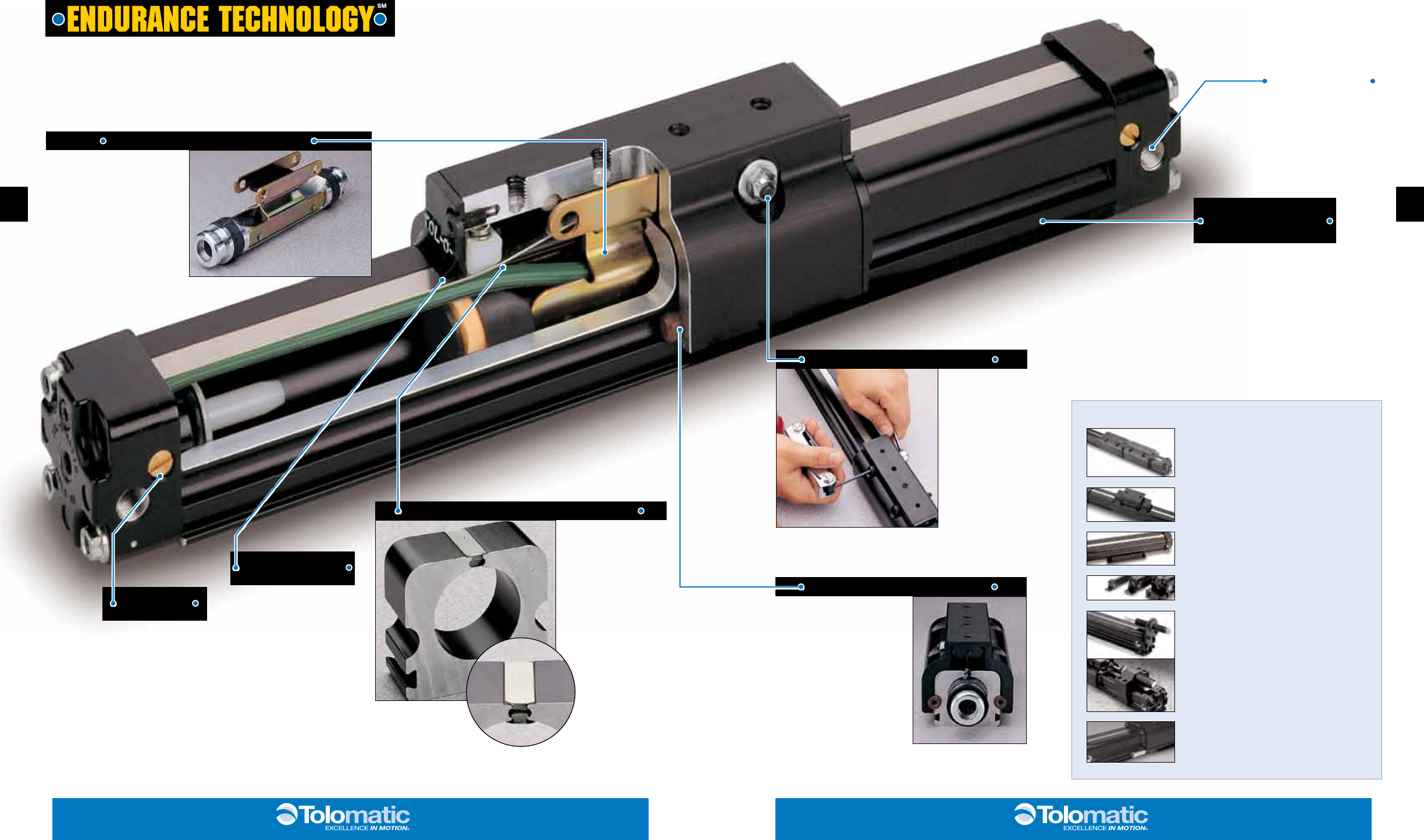
formed steel piston bracket
• Provides maximum strength at
major stress points
• Heat treated carbon steel
withstands the toughest
dynamic forces
• Strongest bracket design in the
industry assures long life with
less maintenance
rigid black-
anodized extruded
aluminum tube
• Stronger, stiffer tube retains
tolerance specs when chamber
is pressurized
• Keeps sealing band in place
for maximized air efficiency
• Tube supports are minimized
• Solid structural support
provides durability and long life
performance
adjustable
cushions
• Adjustable cushions
are standard, not
optional
• Easy screw adjustment
for end-of-stroke
deceleration
• Protects actuator and
load from damage
formed end cap
wiper seal
• Keeps contaminants from
entering the sealing area
• Protects internal
components
• Reduces maintenance while
increasing productivity
stainless steel sealing band system
• Fatigue resistant
stainless steel bands
are specifically made to
provide longer life and
will not elongate, like
elastomers
• Outer band keeps
out contaminants for
extended performance
• Inner band provides
a smooth surface
for less seal wear
load-bearing carrier design
• Load and piston are
independent - piston floats,
resulting in less friction and
longer seal life
• Engineered resin load bearings
offer consistently low friction
and long wear
adjustable carrier bracket
• 2-bolt adjustment
instead of a series
of set screws
• Easy to set tension
for freer running or
stiffer systems
• Minimizes free play
while maintaining a
higher level of load
guidance
3-ported heads
• Standard feature
• Simplifies air connections
Endurance Technology features are
designed for maximum durability to
provide extended service life.
The BC2 is the direct descendent of the industry’s first pneumatic rodless cylinder, manufactured by Tolomatic, the number one rodless
supplier. Featuring durable stainless steel bands, field replaceable engineered bearings and a large carrier mounting pattern the BC2 is
a great solution for applications that require increased Mx bending moment capacity. Built-to-order in stroke lengths up to 350 inches.
bC2 bAnd Cylinder
toloMAtiC … the rodleSS Cylinder leAder
Abt Mxp bC2 bC3 bC4 lS Mg CC pb engr
engr pb CC Mg lS bC4 bC3 bC2 Mxp Abt
2-2 3-3
BC2_4 1.800.328.2174
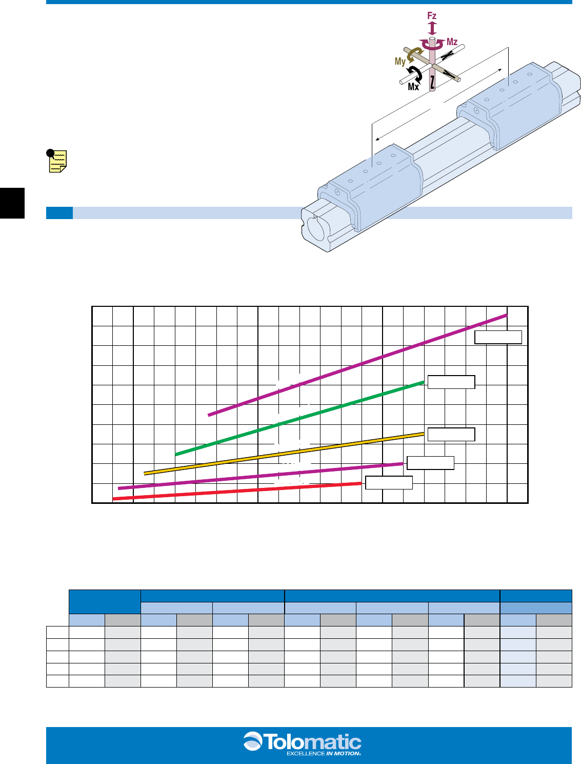
BC2 Solid Bearing Rodless Cylinder
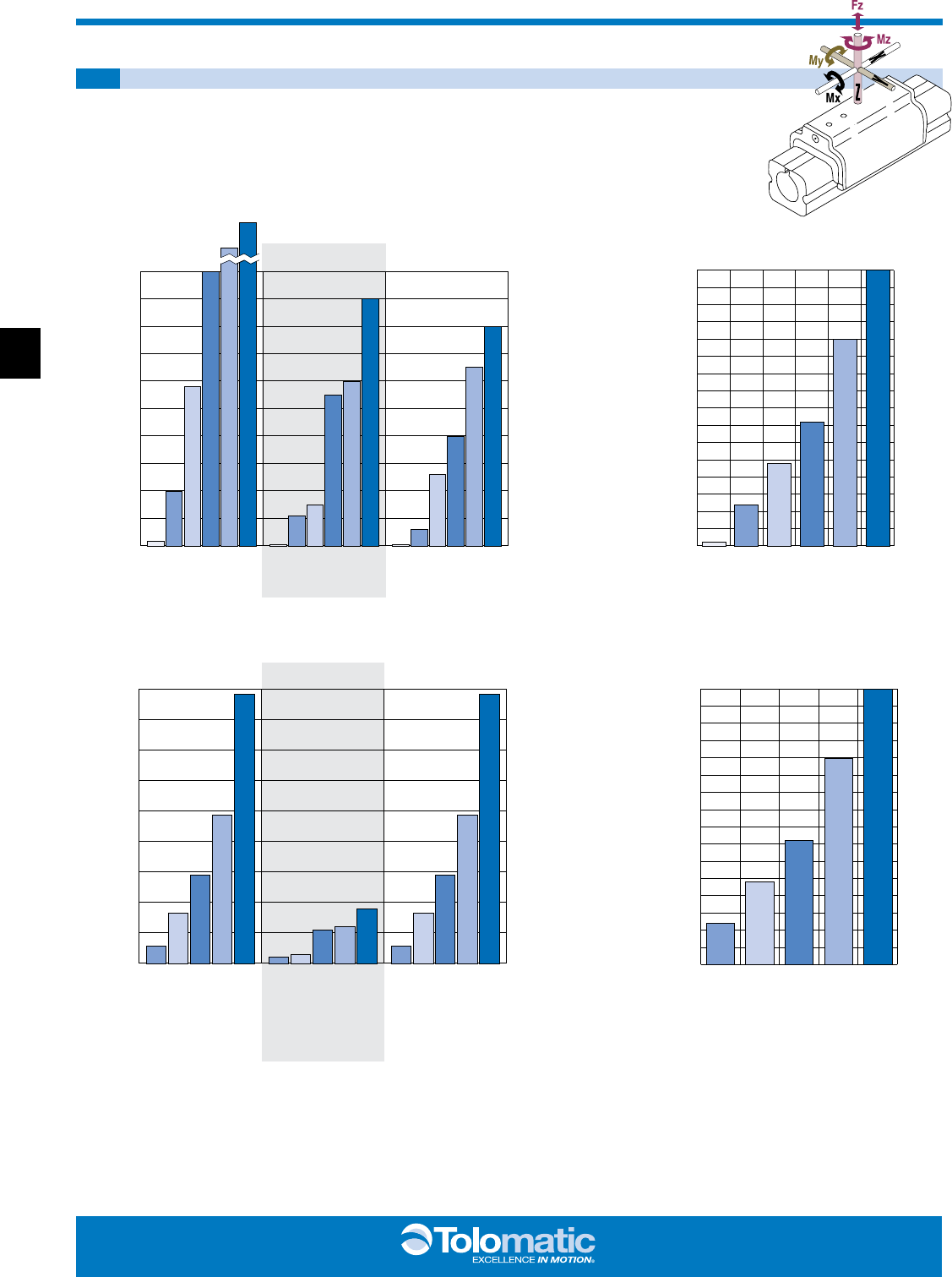
PERFORMANCE
BC2 BENDING MOMENTS AND LOAD, ALL SIZES
0
11.3
22.6
33.9
45.2
56.5
0
56.5
113.0
169.5
226.0
282.5
339.0
395.5
452.0
508.5
Mx MzMy
Mx MzMy
BENDING MOMENTS
STANDARD ACTUATOR
INCH-POUNDS
NEWTON-METERS
INCH-POUNDS
NEWTON-METERS
BC210DO/DW
BC212DO/DW
BC215DO/DW
BC220DO/DW
BC225DO/DW
BC210DO/DW
BC212DO/DW
BC215DO/DW
BC220DO/DW
BC225DO/DW
BC210DO/DW
BC212DO/DW
BC215DO/DW
BC220DO/DW
BC225DO/DW
BC205
BC210
BC212
BC215
BC220
BC225
BC205
BC210
BC212
BC215
BC220
BC225
BC205
BC210
BC212
BC215
BC220
BC225
BC210DO/DW
BC212DO/DW
BC215DO/DW
BC220DO/DW
BC225DO/DW
BC205
BC210
BC212
BC215
BC220
BC225
MAX. LOAD(Fz)
BENDING MOMENTS MAX. LOAD(Fz)
POUNDS
KILOGRAMS
AUXILIARY CARRIER OPTION
0
50
100
150
200
250
300
350
400
0
23
45
68
91
113
136
159
181
POUNDS
KILOGRAMS
0
100
200
300
400
500
600
700
800
0
45
91
136
181
227
272
318
363
1100 1800
500
400
300
200
100
0
4500
4000
3500
3000
2500
2000
1500
1000
500
0
*Auxiliary carrier bending moments indicated are at minimum center to center distance. Additional My + Mz load
capacity can be obtained by increasing “D” dimension. Refer to auxiliary carrier data on page BC2_14.
* *
ABT MXP BC2 BC3 BC4 LS MG CC PB ENGR
44
www.tolomatic.com
BC2_5
BC2 Solid Bearing Rodless Cylinder
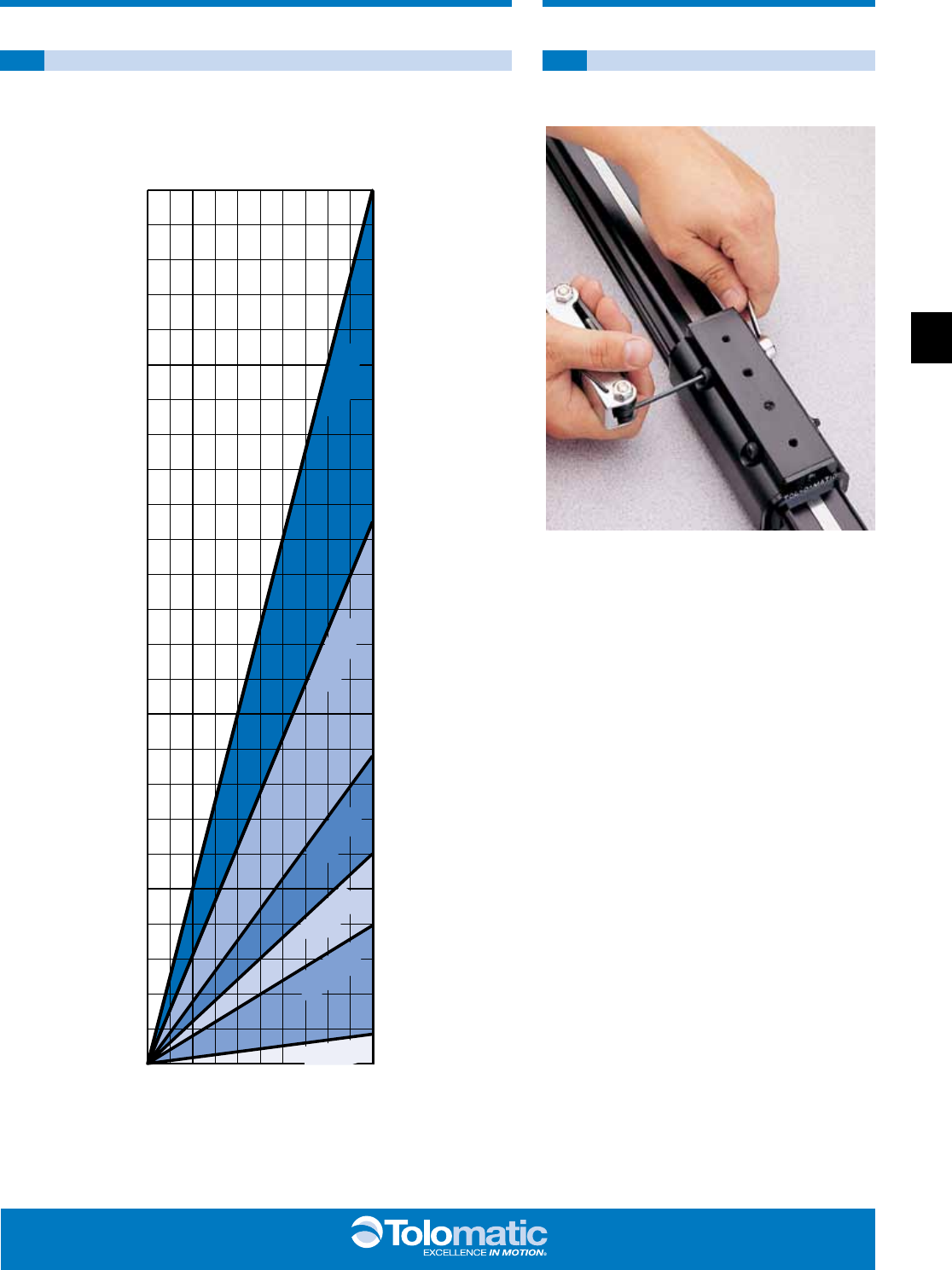
PERFORMANCE GUIDELINES
BC2 THEORETICAL FORCE vs PRESSURE BC2 CARRIER BRACKET
BOLT ADJUSTMENT
20
40
60
80
100
1.4
2.8
4.2
5.6
6.9
500
400
300
200
100
0
227
181
136
91
45
0
FORCE (pounds)
FORCE (kilograms)
PRESSURE (bars)
PRESSURE (PSI)
BC205
BC210
BC212
BC215
BC220
BC225
BC2 carrier bracket adjustment bolts should
be adjusted to suit each individual application,
depending on the degree of rigidity required. A good
starting point is to tighten the nut on the bolt until
there is no lateral movement of the bolt. Then, equally
tighten each nut on the carrier bolt while moving
the carrier by hand along the length of the stroke.
When all lateral play in the carrier is eliminated and
free movement along the length of the stroke is
maintained, your carrier bracket is adjusted properly.
Some applications may require fine tuning of this
adjustment to gain more lateral play or a higher
degree of rigidity. In demanding applications, carrier
adjustments should be done periodically.
ENGR PB CC MG LS BC4 BC3 BC2 MXP ABT
55
BC2_6 1.800.328.2174
LOAD (lbs)
FINAL VELOCITY (in/sec)
FINAL VELOCITY (meters/sec)
50
40
30
20
10
98
76
54
3
2
1
1
2
3
4
5
.5
.9
1.4
1.8
2.3
LOAD (kg)
1.3
1.0
.80
.50
.25 .23
.20 .18
.15 .13
.10
.08
.05
.03
15 .30
5
4
3
2
1
0
Max Distance Between Supports (in) “L”
LOAD WEIGHT (lbs)
LOAD WEIGHT (kg)
2.3
1.8
1.4
.9
.5
0
012 24 36 48 58
0
304.8
609.6
914.4
1219.2
1473.2
Max Distance Between Supports (mm) “L”
Maximum Allowable Load
PRESSURE (PSI)
FORCE (lbs)
FORCE (kg)
.7
1.4
2.1
2.8
3.4
4.2
4.8
5.6
6.2
6.9
PRESSURE (bar)
10 20 30 40 50 60 70 80 90 100
0
2
4
6
8
10
12
14
16
18
20 9.1
8.2
7.3
6.4
5.4
4.5
3.6
2.7
1.8
.9
0
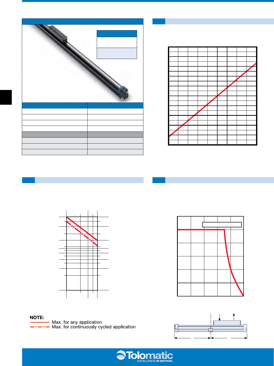
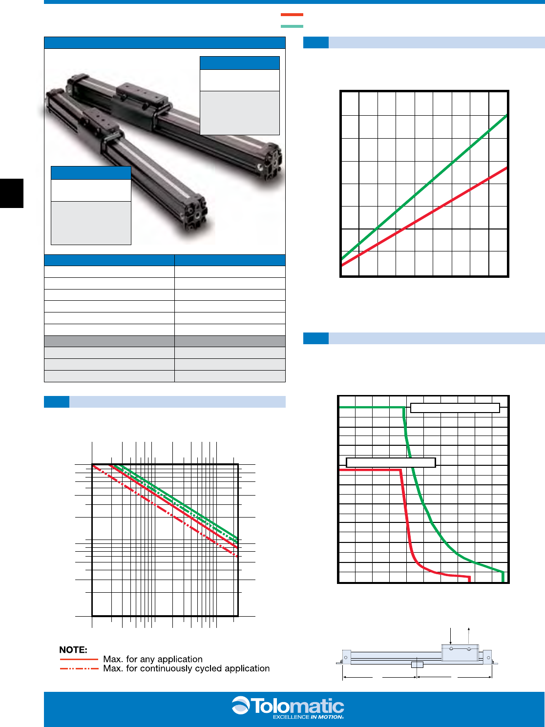
BC205 Solid Bearing Rodless Cylinder
PERFORMANCE
THEORETICAL FORCE vs PRESSURE
BUMPER DAMPENING TUBE SUPPORT REQUIREMENTS
L
L
W
BC205
BC205 OPTIONS Page
Floating Mount BC2_18
Foot Mount BC2_17
Switches BC2_20
Tube Supports BC2_16
MORE INFORMATION Page
Application Guidelines BC2_26
Ordering BC2_28
Selection BC2_25
ORDER CODES
BC205
inch (U.S. Standard)
BC2M05
(metric with taper port)
ABT MXP BC2 BC3 BC4 LS MG CC PB ENGR
66
www.tolomatic.com
BC2_7
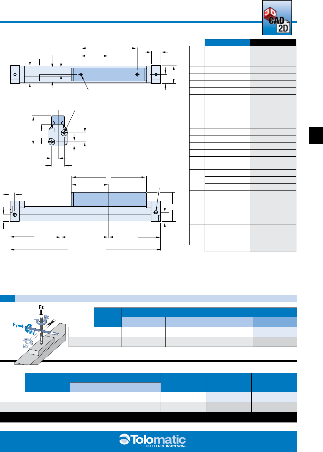
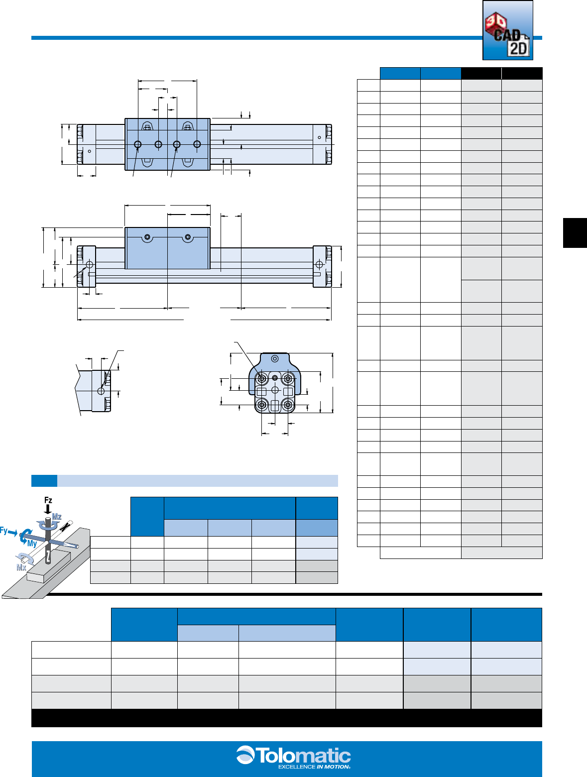
BC205 Solid Bearing Rodless Cylinder
SPECIFICATIONS
DIMENSIONS
BC205 BENDING MOMENTS AND LOAD
C
D
A
B
HH
JK
LI
V
BB
AA
DD
JJ
FF Q
EE
TOLOMATIC
STROKE + 2X
T
U
XSTROKE
N
G
E
F
S
X
05 M05
A0.97 24.6
B0.48 12.3
C3.00 76.2
D1.50 38.1
E0.36 9.1
F0.25 6.35
G0.49 12.4
I0.45 11.45
J0.70 17.8
K0.35 8.9
L0.90 22.9
N1.55 39.4
Q1.09 27.7
S#10-32 UNF M5
T4.00 101.6
U2.00 50.8
V2x #6-32 UNC
x .38 DEEP M3 x 9.7 DEEP
X*
2.60 @ 80-100 PSI 66.0 @ 80-100 PSI
2.66 @ 40-80 PSI 67.6 @ 40-80 PSI
2.71 @ 0-40 PSI 68.8 @ 0-40 PSI
AA 0.33 8.4
BB 0.66 16.8
DD 0.48 12.2
EE 4x #6-32UNC
x .25 DEEP M3 x 6.4 DEEP
FF 1.55 39.4
HH 0.50 12.7
JJ 0.17 4.3
INCHES MILLIMETERS
ORDER
CODE
BORE
SIZE
MAX. BENDING MOMENT MAX. LOAD
My Mx Mz Fz
05 0.50 in 9.0 in-lbs 2.0 in-lbs 3.0 in-lbs 5.0 lbs
M05 12 mm 1.01 N-m 0.22 N-m 0.33 N-m 2.27 kg
BORE SIZE WEIGHT MAX. STROKE
LENGTH*
MAX.
PRESSURE
TEMPERATURE
RANGE
BASE PER UNIT OF STOKE
05 0.50 in 0.38 lb 0.036 lb/in 171 in 100 PSI 20° to 140° F
M05 12 mm 0.169 kg 0.0164 kg/mm 4343 mm 6.895 bar -7° to 60° C
*For longer strokes, alternate materials, mounting and/or fasteners – consult Tolomatic
3d cad available at
www.tolomatic.com
ENGR PB CC MG LS BC4 BC3 BC2 MXP ABT
77
BC2_8 1.800.328.2174
LOAD (lbs)
FINAL VELOCITY (in/sec)
LOAD (kg)
FINAL VELOCITY (meters/sec)
2.5 2.3
2.0 1.8
1.5 1.3
1.0
.7
.5
.25
.23 .20
.18 .15
.13 .10
.08
.05
.03
100
90 80
70 60
50
40
30
20
10 9
87
65
4
3
2
1
1
2
3
4
5
6
7
8
9
10
20
30
40
50
60
70
80
90
100
.5
.9
1.4
1.8
2.7 3.2
3.6 4.1
4.5
9.1
13.6
18.1
22.7 27.2
31.7 36.3
40.8 45.4
2.3
60
55
50
45
40
35
30
25
20
15
10
5
0
27.2
24.9
22.7
20.4
18.1
15.9
13.6
11.3
9.1
6.8
4.5
2.3
0
Max Distance Between Supports (in) “L”
LOAD WEIGHT (lbs)
LOAD WEIGHT (kg)
0 12 24 36 48 60 72 84 96 108
0
304.8
609.6
914.4
1219.2
1524
1828.8
2133.6
2438.4
2743.2
Max Distance Between Supports (mm) “L”
Maximum Allowable Load
PRESSURE (PSI)
FORCE (lbs)
0
10
20
30
40
50
60
70
80
0
4.5
9.1
16.6
18.1
22.7
27.2
31.7
36.3
FORCE (kg)
.7
1.4
2.1
2.8
3.4
4.2
4.8
5.6
6.2
6.9
PRESSURE (bar)
10 20 30 40 50 60 70 80 90 100
THEORETICAL FORCE VS. PRESSURE
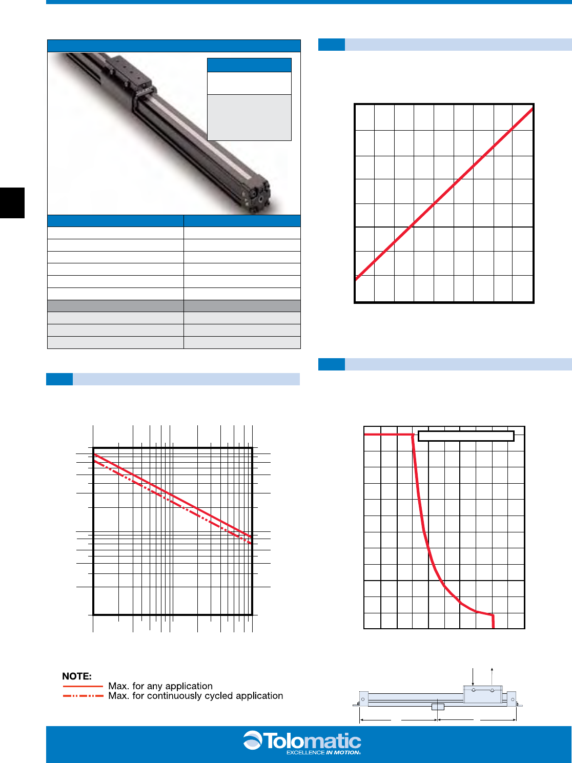
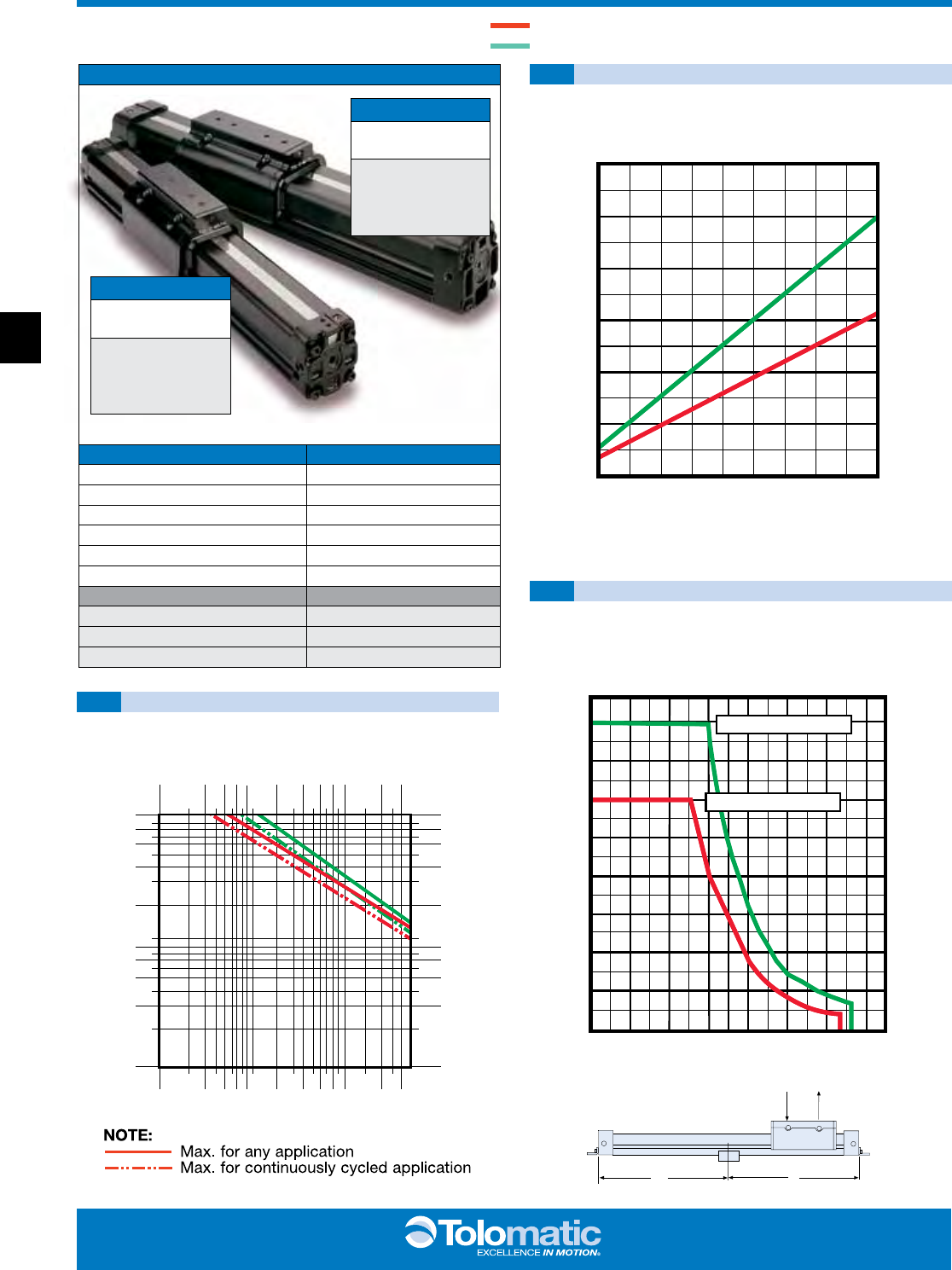
BC210 Solid Bearing Rodless Cylinder
PERFORMANCE
THEORETICAL FORCE vs PRESSURE
CUSHION DATA
TUBE SUPPORT REQUIREMENTS
L
L
W
BC210
BC210 OPTIONS Page
Auxiliary Carrier BC2_14
Floating Mount BC2_18
Foot Mount BC2_17
Shock Absorbers BC2_22
Switches BC2_20
Tube Supports BC2_16
MORE INFORMATION Page
Application Guidelines BC2_26
Ordering BC2_28
Selection BC2_25
ORDER CODES
BC210
inch (U.S. Standard)
BC2M10
(metric with taper port)
BC2MM10
(metric with parallel port)
ABT MXP BC2 BC3 BC4 LS MG CC PB ENGR
88
www.tolomatic.com
BC2_9
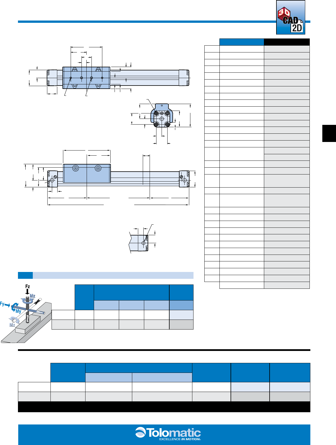
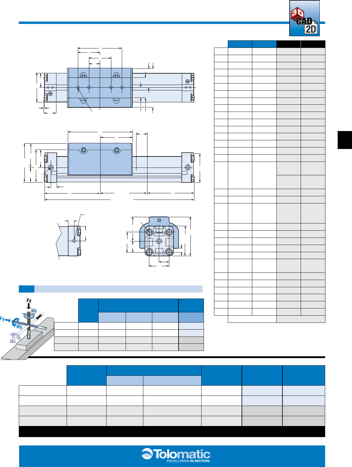
BC210 Solid Bearing Rodless Cylinder
SPECIFICATIONS
DIMENSIONS
BC210 BENDING MOMENTS AND LOAD
U
T
X
STROKE
X
STROKE + 2X
S
P
O
R
N
GG
REF Q
MM
PP CUSHION STROKE
LENGTH
JI
HG
V
Z
C
D
E
F
B
A
JJ
OO
EE
NN
DD
CC
BB
AA
GG
Q REF
TOLOMATIC
B
OPTIONAL 4th PORT
LOCATION
MM
T
O
L
O
M
A
T
I
C
10 M(MM)10
A1.58 40.1
B0.79 20.1
C3.15 80.0
D1.57 40.0
E1.00 25.4
F0.50 12.7
G0.65 16.5
H1.30 33.0
I1.09 27.7
J2.18 55.4
N1.62 41.2
O1.88 47.7
P1.20 30.5
Q1.64 41.5
R0.68 17.3
S1/8 NPT (3) M 1/8 BSPT(3)
MM1/8 BSPP(3)
T4.75 120.7
U2.37 60.2
V1/4-20 UNC X .25
DEEP M6 X 6 DEEP
X3.94 100.1
Z10-32 UNC X .25
DEEP M6 X 6 DEEP
AA 0.55 14.0
BB 1.10 27.9
CC 0.55 14.0
DD 1.10 27.9
EE 10-24 X .43 DEEP M5 X 11.0 DEEP
GG 2.30 58.4
JJ 1.00 25.4
MM 0.55 14.0
NN 1.50 38.1
OO 0.18 4.7
PP 0.68 17.3
INCHES MILLIMETERS
BORE
SIZE
MAX. BENDING MOMENT MAX.
LOAD
My Mx Mz Fz
10 1.00 in 100 in-lbs 55 in-lbs 30 in-lbs 60 lbs
M(MM)10
25 mm 11.29 N-m 6.21 N-m 3.39 N-m 27.21 kg
BORE SIZE WEIGHT MAX. STROKE
LENGTH*
MAX.
PRESS URE
TEMPERATURE
RANGE
BASE PER UNIT OF STOKE
10 1.00 in 2.26 lbs 0.14 lbs/in 350 in 100 PSI 20° to 140° F
M(MM)10 25 mm 1.025 kg 0.0024 kg/mm 8890 mm 6.895 bar -7° to 60° C
*For longer strokes, alternate materials, mounting and/or fasteners – consult Tolomatic
3D CAD AVAILABLE AT
WWW.TOLOMATIC.COM
ENGR PB CC MG LS BC4 BC3 BC2 MXP ABT
99
BC2_10 1.800.328.2174
12345678910 20 30 405060
70
80
90
100 200
1
2
3
4
56
78
910
20
30
40 50
60 70
80 90
100 2.5
2.3 2.0
1.8 1.5
1.3 1.0
.8
.5
.3 .23
.20 .18
.15 .13
.10
.08
.05
.03
.5
.9
1.4
1.81
2.7 3.2
3.6 4.1
4.5
9.1
13.6 18.1
22.7 27.2
31.7 36.3
40.8 45.4
2.3
90.7
LOAD (lbs)
FINAL VELOCITY (in/sec)
LOAD (kg)
FINAL VELOCITY (meters/sec)
180
160
140
120
100
80
60
40
20
0
81.6
72.6
63.5
54.4
45.4
36.3
27.2
18.1
9.1
0
0 12 24 36 48 60 72 84 96 108 120
304.8
609.6
914.4
1219.2
1524.0
1828.8
2133.6
2438.4
2743.2
3048.0
Maximum Allowable Load
Maximum Allowable Load
Max Distance Between Supports (in) “L”
Max Distance Between Supports (mm) “L”
LOAD WEIGHT (lbs)
LOAD WEIGHT (kg)
10 20 30 40 50 60 70 80 90 100
0
25
50
75
100
125
150
175
200
90.7
79.4
68.0
56.7
45.4
34.0
22.7
11.3
0
.7
1.4
2.1
2.8
3.4
4.2
4.8
5.6
6.2
6.9
PRESSURE (PSI)
FORCE (lbs)
FORCE (kg)
PRESSURE (bar)
BC212 & BC215 Solid Bearing Rodless Cylinder
PERFORMANCE
THEORETICAL FORCE vs PRESSURE
CUSHION DATA
TUBE SUPPORT REQUIREMENTS
L
L
W
BC212 & BC215
BC212 & BC215 OPTIONS Page
Auxiliary Carrier BC2_14
Floating Mount BC2_18
Foot Mount BC2_17
Shock Absorbers BC2_22
Switches BC2_20
Tube Supports BC2_16
MORE INFORMATION Page
Application Guidelines BC2_26
Ordering BC2_28
Selection BC2_25
ORDER CODES
BC215
inch (U.S. Standard)
BC2M15
(metric with taper port)
BC2MM15
(metric with parallel port)
ORDER CODES
BC212
inch (U.S. Standard)
BC2M12
(metric with taper port)
BC2MM12
(metric with parallel port)
BC212
BC215
ABT MXP BC2 BC3 BC4 LS MG CC PB ENGR
1010
www.tolomatic.com
BC2_11
BC212 & BC215 Solid Bearing Rodless Cylinder
SPECIFICATIONS
DIMENSIONS
BC212/15 BENDING MOMENTS AND LOAD
EE
Q
REF
GG
NN
DD CC
BB
AA
OO
TOLOMATIC
CUSHION STROKE LENGTHPP
STROKE + 2X
U
T
STROKE
MM
R
O
P
N
GG
REF
J
I
H
G
V
Z
F
E
DC
JJ
AB
S
X
X
Q
B
OPTIONAL 4th PORT
LOCATION
MM
T
O
L
O
M
A
T
I
C
12 15
M(MM)12 M(MM)15
A2.18 2.85 55.4 72.4
B1.09 1.42 27.7 36.1
C3.20 4.25 81.3 108.0
D1.60 2.12 40.6 53.8
E1.00 1.00 25.4 25.4
F0.50 0.50 12.7 12.7
G0.78 0.90 19.8 22.9
H1.56 1.80 39.6 45.7
I1.41 1.75 35.8 44.5
J2.82 3.50 71.6 89.0
N1.83 2.13 46.5 54.1
O2.48 2.95 63.0 74.9
P1.25 1.51 31.0 38.4
Q2.25 2.59 57.2 65.8
R1.23 1.41 31.2 36.6
S1/4 NPT
(3)
1/4 NPT
(3)
M 1/4
BSPT(3)
M 1/4
BSPT(3)
MM 1/4
BSPP(3)
MM 1/4
BSPP(3)
T4.64 5.91 117.9 150.1
U2.32 2.96 58.9 75.1
V
5/16-18
UNC x
.31 DP
1/4-20
UNC x
.38 DP
M8 x 7
DP
M8 x 10
DP
X4.87 5.91 123.7 150.1
Z
1/4-20
UNC x
.31 DP
5/16-18
UNC x
.38 DP
M8 x 7
DP
M8 x 10
DP
AA 0.71 0.91 18.0 23.1
BB 1.42 1.81 36.1 46.0
CC 0.78 1.03 19.8 26.2
DD 1.42 1.81 36.1 46.0
EE 1/4-20 x
.47 DP
1/4-20 x
.47 DP
M6 x 12
DP
M6 x 12
DP
GG 3.06 3.54 77.7 90.7
JJ 1.00 1.25 25.4 31.8
MM 0.34 0.50 8.6 12.7
NN 1.83 2.13 46.5 54.1
OO 0.35 0.28 9.0 7.0
PP 1.10 1.29 27.9 32.7
INCHES MILLIMETERS
BORE
SIZE
MAX. BENDING MOMENT MAX.
LOAD
My Mx Mz Fz
12 1.25 in 290 in-lbs 75 in-lbs 130 in-lbs 120 lbs
15 1.50 in 500 in-lbs 275 in-lbs 200 in-lbs 180 lbs
M(MM)12
32 mm 32.77 N-m 8.47 N-m 14.69 N-m 54.42 kg
M(MM)15
40 mm 56.49 N-m 31.07 N-m 22.60 N-m 81.63 kg
BORE
SIZE
WEIGHT MAX. STROKE
LENGTH*
MAX.
PRESS URE
TEMPERATURE
RANGE
BASE PER UNIT OF STOKE
12 1.25 in 4.56 lbs 0.21 lbs/in 288 in 100 PSI 20° to 140° F
15 1.50 in 8.18 lbs 0.34 lbs/in 298 in 100 PSI 20° to 140° F
M(MM)12 32 mm 2.068 kg 0.0036 kg/mm 7315 mm 6.895 bar -7° to 60° C
M(MM)15 40 mm 3.7 kg 0.0058 kg/mm 7569 mm 6.895 bar -7° to 60° C
*For longer strokes, alternate materials, mounting and/or fasteners – consult Tolomatic
3d cad available at
www.tolomatic.com
ENGR PB CC MG LS BC4 BC3 BC2 MXP ABT
1111
BC2_12 1.800.328.2174
1
2
3
4
5
6
7
8
9
10
20
30
40
50
60
70
80
90
100
200
300
400
500
30
40 50
60 70
80 90
100
1
2
34
56
78
910
20
2.5
2.3 2.0
1.8 1.5
1.3 1.0
.8
.5
.3 .23
.20 .18
.15 .13
.10
.08
.05
.03
.5
.9
1.4
1.8
2.7 3.2
3.6 4.1
4.5
9.1
13.6 18.1
22.7 27.2
31.7 36.3
40.8 45.4
2.3
90.7
136.1
181.4226.8
LOAD (lbs)
FINAL VELOCITY (in/sec)
LOAD (kg)
FINAL VELOCITY (meters/sec)
0 12 24 36 48 60 72 84 96 108 120 132 144 156 168
0
304.8
609.6
914.4
1219.2
1524.0
1828.8
2133.6
2438.4
2743.2
3048.0
3352.8
3657.6
3962.4
4267.2
400
350
300
250
200
150
100
50
0
181.4
158.7
136.1
113.4
90.7
68.0
45.4
22.7
0
Maximum Allowable Load
Maximum Allowable Load
Max Distance Between Supports (in) “L”
Max Distance Between Supports (mm) “L”
LOAD WEIGHT (lbs)
LOAD WEIGHT (kg)
10 20 30 40 50 60 70 80 90 100
600
500
400
300
200
100
0
272.2
226.8
181.4
136.1
90.7
45.4
0
.7
1.4
2.1
2.8
3.4
4.2
4.8
5.6
6.2
6.9
PRESSURE (PSI)
FORCE (lbs)
FORCE (kg)
PRESSURE (bar)
BC220 & BC225 Solid Bearing Rodless Cylinder
PERFORMANCE
THEORETICAL FORCE vs PRESSURE
CUSHION DATA
TUBE SUPPORT REQUIREMENTS
L
L
W
BC220 & BC225
BC220 & BC225 OPTIONS Page
Auxiliary Carrier BC2_14
Floating Mount BC2_18
Foot Mount BC2_17
Shock Absorbers BC2_22
Switches BC2_20
Tube Supports BC2_16
MORE INFORMATION Page
Application Guidelines BC2_26
Ordering BC2_28
Selection BC2_25
ORDER CODES
BC225
inch (U.S. Standard)
BC2M25
(metric with taper port)
BC2MM25
(metric with parallel port)
ORDER CODES
BC220
inch (U.S. Standard)
BC2M20
(metric with taper port)
BC2MM20
(metric with parallel port)
BC220
BC225
ABT MXP BC2 BC3 BC4 LS MG CC PB ENGR
1212
www.tolomatic.com
BC2_13
BC220 & BC225 Solid Bearing Rodless Cylinder
SPECIFICATIONS
DIMENSIONS
BC220/25 BENDING MOMENTS AND LOAD
TOLOMATIC
TOLOMATIC
EE
NN
DD
CC
BB
AA
OO
Q
REF
GG
C
D
E
F
V
B
A
K
JJ GH
IJ
Q
GG
REF
N
O
P
S
R
MM
X
STROKE
STROKE + 2X
X
U
TPP CUSHION STROKE
LENGTH
B
OPTIONAL
4th PORT
LOCATION
MM
20 25
M(MM)20 M(MM)25
A3.25 4.25 82.6 108.0
B1.62 2.13 41.1 54.1
C5.00 6.00 127.0 152.4
D2.50 3.00 63.5 76.2
E2.50 3.00 63.5 76.2
F1.25 1.50 31.8 38.1
G1.16 1.27 29.5 32.4
H2.30 2.55 58.4 64.8
I2.22 2.81 56.4 71.4
J4.44 5.62 112.8 142.8
K0.06 0.03 1.5 0.8
N2.75 3.20 69.9 81.3
O3.69 4.67 93.7 118.6
P2.00 2.37 50.8 60.2
Q3.38 4.37 85.9 111.0
R1.69 2.30 42.9 58.4
S3/8 NPT
(3)
3/8 NPT
(3)
M 3/8
BSPT(3)
M 3/8
BSPT(3)
MM 3/8
BSPP(3)
MM 3/8
BSPP(3)
T7.37 8.86 187.2 225.0
U3.68 4.43 93.5 112.5
V
3/8-16
UNC x
.44 DP
3/8-16
UNC x
.50 DP
M10 x 11
DP
M10 x 12
DP
X6.30 8.45 160.0 214.6
AA 1.12 1.44 28.5 36.6
BB 2.25 2.88 57.2 73.2
CC 1.25 1.75 31.8 44.5
DD 2.25 2.88 57.2 73.2
EE 5/16-18 x
.88 DP
5/16-18 x
.88 DP
M8 x 22
DP
M8 x 22
DP
GG 4.44 5.50 112.8 139.7
JJ 1.44 2.06 36.6 52.3
MM 0.69 1.00 17.5 25.4
NN 2.75 3.20 69.9 81.3
OO 0.43 0.76 10.9 19.3
PP 1.35 1.97 34.3 50.0
INCHES MILLIMETERS
BORE
SIZE
MAX. BENDING MOMENT MAX.
LOAD
My Mx Mz Fz
20 2.00 in
1,100 in-lbs 300 in-lbs 325 in-lbs
300 lbs
25 2.50 in
1,800 in-lbs 450 in-lbs 400 in-lbs
400 lbs
M(MM)20
50 mm
124.28 N-m 33.90 N-m 36.72 N-m
136.05 kg
M(MM)25
63 mm
203.37 N-m 50.84 N-m 45.19 N-m
181.4 kg
BORE
SIZE
WEIGHT MAX. STROKE
LENGTH*
MAX.
PRESS URE
TEMPERATURE
RANGE
BASE PER UNIT OF STOKE
20 2.00 in 14.12 lbs 0.54 lbs/in 274 in 100 PSI 20° to 140° F
25 2.50 in 31.90 lbs 1.01 lbs/in 163 in 100 PSI 20° to 140° F
M(MM)20 50 mm 6.4 kg 0.0093 kg/mm 6959 mm 6.895 bar -7° to 60° C
M(MM)25 63 mm 14.467 kg 0.0173 kg/mm 4140 mm 6.895 bar -7° to 60° C
*For longer strokes, alternate materials, mounting and/or fasteners – consult Tolomatic
3d cad available at
www.tolomatic.com
ENGR PB CC MG LS BC4 BC3 BC2 MXP ABT
1313
BC2_14 1.800.328.2174
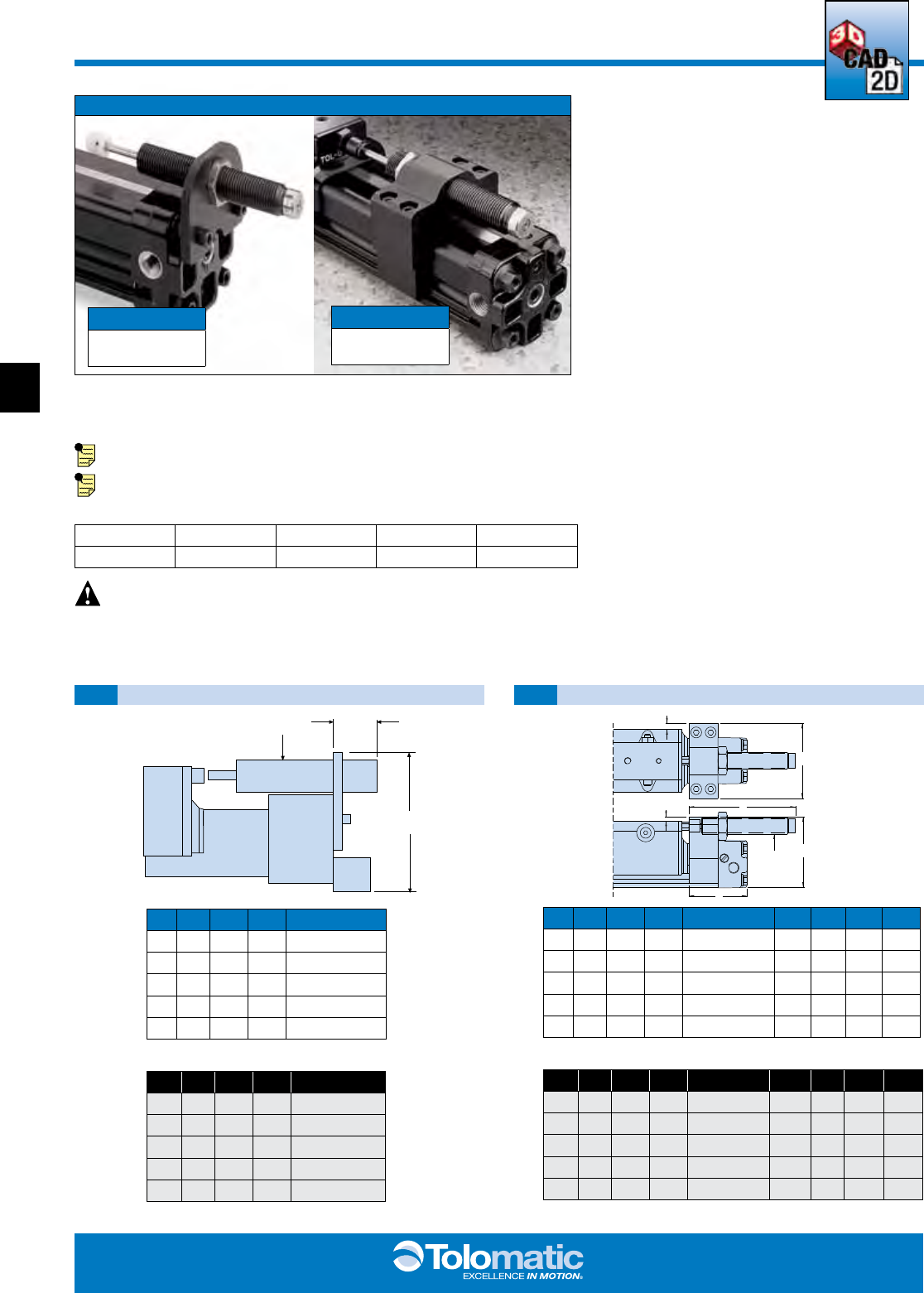
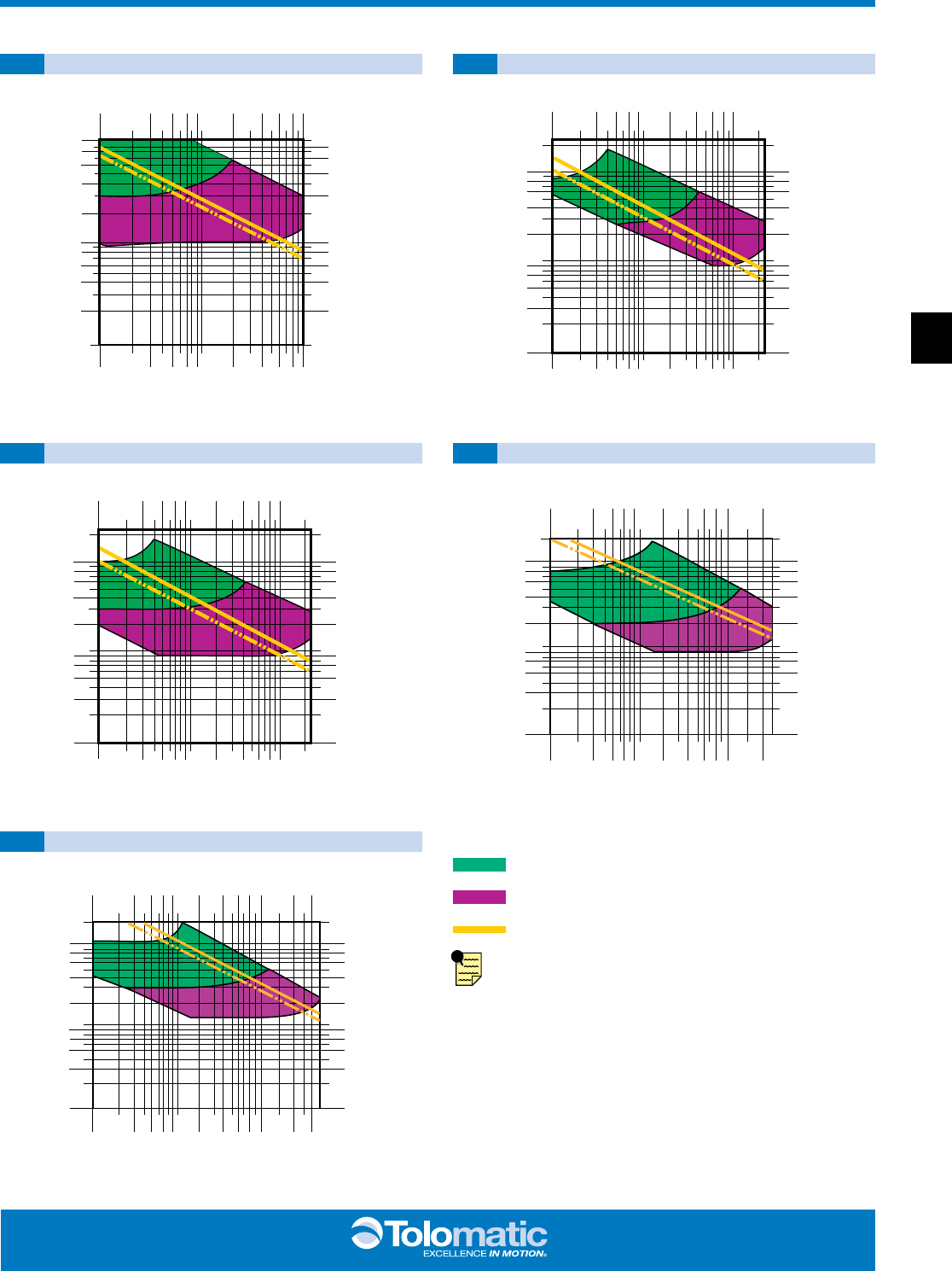
BC2 Auxiliary Carrier - 10, 12, 15, 20, 25 Sizes
PERFORMANCE
BENDING MOMENTS
BC220
BC225
Rates were calculated with the following assumptions:
1.) Coupling between carriers is rigid. 2.) Load is equally distributed between carriers.
3.) Coupling device applies no misalignment loads to carriers.
MOMENT LOAD vs. DISTANCE
10,000
9,000
8,000
7,000
6,000
5,000
4,000
3,000
2,000
1,000
0
4 5 6 7 8 9 10 11 12 13 14 15 16 17 18 19 20 21 22 23 24 25
2.50" BORE
2.00" BORE
1.50" BORE
1.25" BORE
1.00" BORE
D (in)
Mya & Mza (in-lbs)
D (mm)
1,130
1,017
904
791
678
565
452
339
226
113
0
My
a
& Mz
a
(N-m)
BC225DW
BC220DW
BC215DW
BC212DW
BC210DW
BC225DW
BC220DW
BC215DW
BC212DW
BC210DW
102
127
152
178
203
229
254
279
305
330
356
381
406
432
457
483
508
533
559
584
610
635
“D”
CARRIER
C
L
CARRIER
C
L
BORE SIZE “D” MINIMUM * MAX. BENDING MOMENT MAX. LOAD
(w/o Piston) (w/ Piston) My** Mx Mz** Fz
in mm
in mm in mm in-lbs N-m in-lbs N-m in-lbs N-m
lbs kg
10 1.00 25
5.07 129.0 5.07 129.0 287 32.4 110 12.4 287 32.4
120 54.4
12 1.25 32
5.17 131.0 6.85 174.0 822 92.9 150 16.9 822 92.9
240 108.9
15 1.50 40
6.46 164.0 8.07 205.0 1,453 164.1 550 62.1 1,453 164.1
360 163.3
20 2.00 50
8.10 206.0 8.10 206.0 2,430 274.6 600 67.8 2,430 274.6
600 272.2
25 2.50 63
9.62 244.0 11.04 2810.4 4,416 498.9 900 101.7 4,416 498.9
800 362.9
* “D” is distance between carriers
** Loads calculated are at minimum “D”, for substantially higher My and Mz loads increase “D” and refer to graph above
The auxiliary carrier option substantially increases load
carrying and bending moments capacity over the standard
single carrier models. As a general rule, the auxiliary carrier
option is highly recommended in vertical applications (My) if
the distance from the carrier mounting surface to the load
center of gravity (CG) exceeds the overall length of the carrier.
Auxiliary carriers can be ordered with (DW) or without (DO)
an internal piston. (Auxiliary carriers without a piston have no
cushion on the cylinder end closest to the auxiliary carrier.)
NOTE: breakaway pressure will increase when using
auxiliary carrier.
ABT MXP BC2 BC3 BC4 LS MG CC PB ENGR
1414
www.tolomatic.com
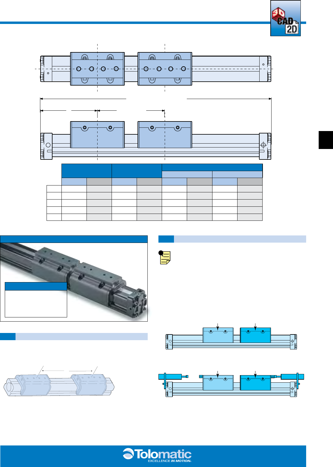
BC2_15
BC2 Auxiliary Carrier - 10, 12, 15, 20, 25 Sizes
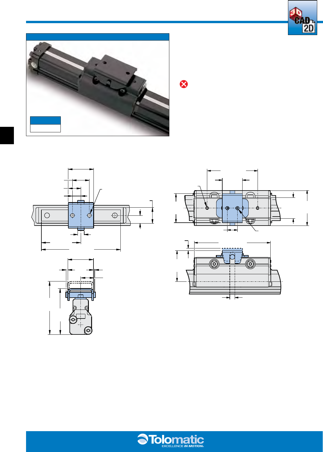
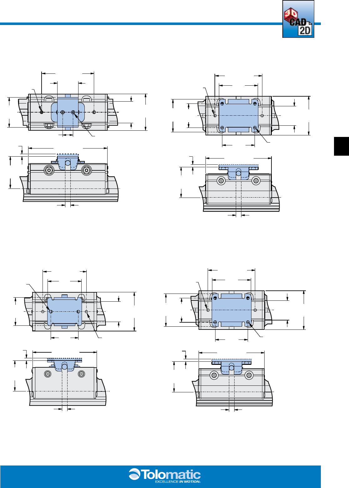
DIMENSIONS
ASSEMBLY INFORMATION
AUXILIARY CARRIERMAIN CARRIER
AUXILIARY CARRIERMAIN CARRIER
2A + “D” + STROKE
“D” (Min.)A
C
LC
L
BORE SIZE A “D” MINIMUM *
(w/o Piston) (w/ Piston)
in mm in mm
in mm in mm
10 1.00 25 3.94 100.1
5.07 129.0 5.07 129.0
12 1.25 32 4.90 124.5
5.17 131.0 6.85 174.0
15 1.50 40 5.91 150.1
6.46 164.0 8.07 205.0
20 2.00 50 6.30 160.0
8.10 206.0 8.10 206.0
25 2.50 63 8.46 214.9
9.62 244.0 11.04 280.4
AUXILIARY CARRIER
ORDER CODES
DO
(Auxiliary Carrier without piston)
DW
(Auxiliary Carrier with piston)
ORDERING INFORMATION
When ordering, determine the minimum distance required
between carriers (dimension “D” in Auxiliary Carrier Bending
Moments chart).
Determine your working stroke and your “D” dimension,
then enter these into your configuration string. (Example:
BC215SK50.00DW15.00RT2) The configurator will calculate
the overall length of the actuator.
IMPORTANT INFORMATION REGARDING AUXILIARY
CARRIER PLACEMENT
When a BC2 cylinder is ordered with auxiliary carrier, it is
always placed to the right (while facing the switch mounted
or open port side) of the main carrier. This is for auxiliary
carriers with (DW)/or without (DO) piston and for units with/
or without shock absorbers. When the auxiliary carrier is
ordered without (DO) piston the carrier without piston will be
marked.
“D”
CARRIER
C
L
CARRIER
C
L
3d cad available at
www.tolomatic.com
ENGR PB CC MG LS BC4 BC3 BC2 MXP ABT
1515
BC2_16 1.800.328.2174
(CARRIER NOT SHOWN)
B
C
D
A
TOLOMATIC
K
J
L
H
E
GFK
J
L
H
TOLOMATIC
(CARRIER NOT SHOWN)
B
C
D
A
TOLOMATIC
K
J
L
H
E
GFK
J
L
H
TOLOMATIC
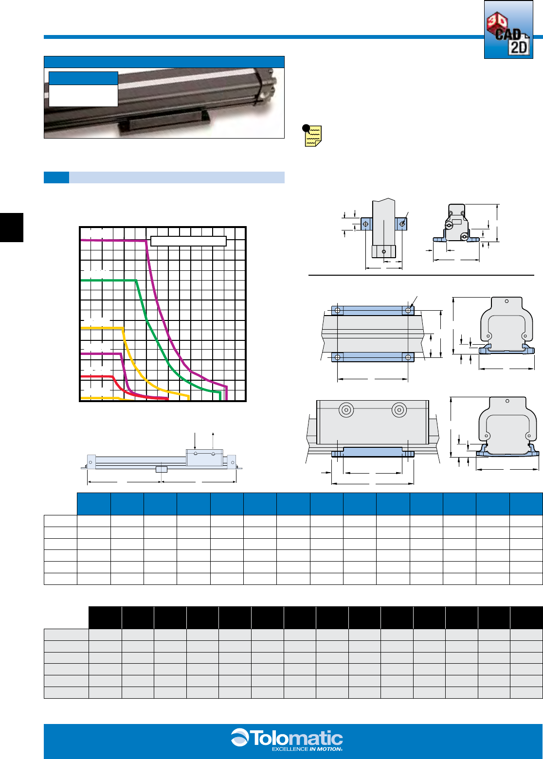
BC2 Tube Supports - ALL Sizes
PERFORMANCE
DIMENSIONS
Tube supports are mounted to the BC2 band cylinder during
assembly procedure. Made of black-anodized aluminum,
tube supports are designed to fit into dovetail grooves which
run the length of the cylinder tube. Refer to the tube support
graph to determine the number of tube supports required.
NOTE: Switches cannot be mounted on the same face
of the actuator as tube supports.
BORE
SIZE A Ø B C D E F G H J K L M N
05 0.50
0.18 0.75 1.50
– 0.50 – – 0.18 0.54 1.88 1.60 0.65 0.50
10 1.00
0.22 1.00 2.00
3.00 3.50 2.50 0.50 0.25 0.41 2.36 2.43 – –
12 1.25
0.27 1.31 2.63
4.50 5.00 4.00 0.50 0.40 0.81 3.12 3.23 – –
15 1.50
0.27 1.50 3.00
4.50 5.00 4.00 0.50 0.31 0.70 3.50 3.62 – –
20 2.00
0.41 1.875 3.750
5.75 6.38 5.00 0.69 0.375 0.87 4.44 4.53 – –
25 2.50
0.42 2.563 5.125
7.75 8.50 7.00 0.75 0.437 1.17 6.00 5.56 – –
Dimensions in inches
BORE
SIZE A Ø B C D E F G H J K L M N
M(MM)05 12
4.6 19.1 38.1
– 12.7 – – 4.6 13.7 47.7 40.6 16.5 12.7
M(MM)10 25
5.6 25.4 50.8
76.2 88.9 63.5 12.7 6.3 10.4 59.9 61.7 – –
M(MM)12 32
6.7 33.3 66.8
114.3 127.0 101.6 12.7 10.2 20.6 79.2 82.0 – –
M(MM)15 40
6.7 38.1 76.2
114.3 127.0 101.6 12.7 7.9 17.8 88.9 91.9 – –
M(MM)20 50
10.5 47.6 95.3
146.1 162.1 127.0 17.5 9.5 22.1 112.8 115.1 – –
M(MM)25 63
10.7 65.1 130.2
196.9 215.9 177.8 19.1 11.1 29.7 152.4 141.2 – –
Dimensions in millimeters
EM
C
B
A
K
L
NH
J
TOLOMATIC
EM
C
B
A
K
L
NH
J
TOLOMATIC
TUBE SUPPORT
ORDER CODE
TS_
(_ = Number ordered)
0 12 24 36 48 60 72 84 96 108 120 132 144 156 168
0
304.8
609.6
914.4
1219.2
1524.0
1828.8
2133.6
2438.4
2743.2
3048.0
3352.8
3657.6
3962.4
4267.2
400
350
300
250
200
150
100
50
0
181.4
158.7
136.1
113.4
90.7
68.0
45.4
22.7
0
Maximum Allowable Load
Max Distance Between Supports (in.) “L”
Max Distance Between Supports (mm) “L”
LOAD WEIGHT (Lbs.)
LOAD WEIGHT (Kgs.)
BC225
BC220
BC215
BC212
BC210
BC205
BC225
BC220
BC215
BC212
BC210
BC205
TUBE SUPPORT REQUIREMENTS
05
10, 12, 15, 20, 25
10, 12, 15, 20, 25
10, 12, 15, 20
25
L
L
W
3d cad available at
www.tolomatic.com
ABT MXP BC2 BC3 BC4 LS MG CC PB ENGR
1616
www.tolomatic.com
BC2_17
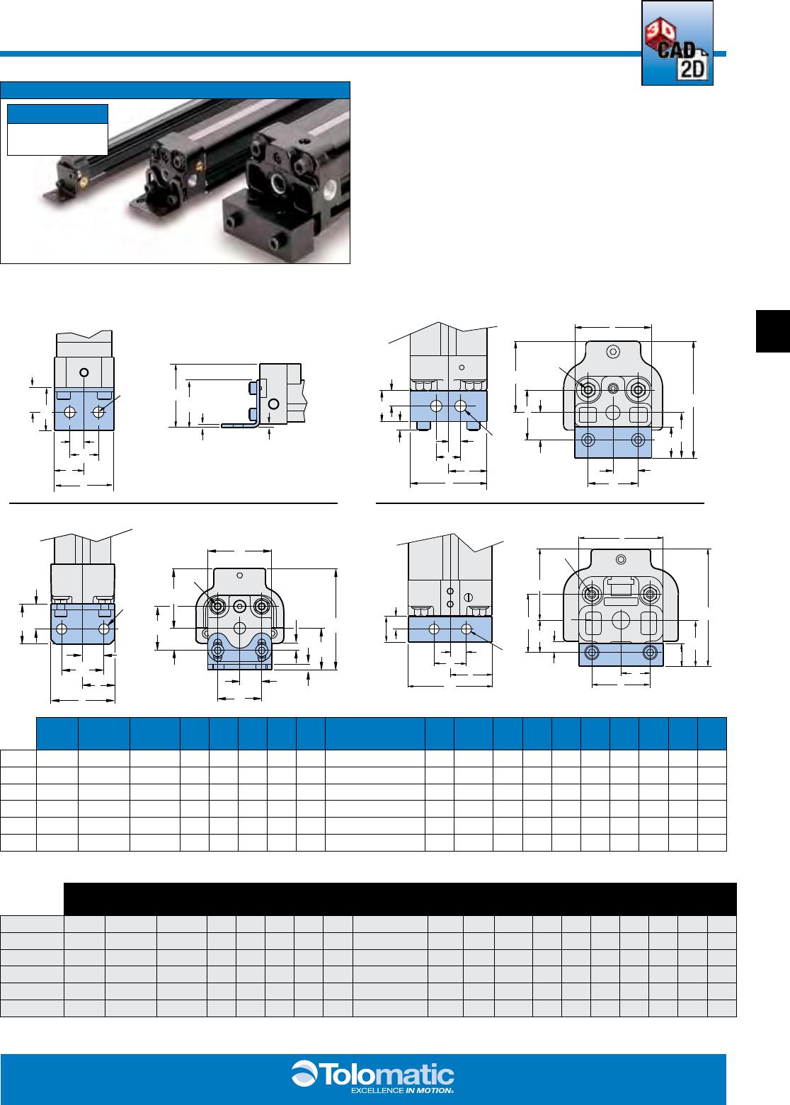
BC2 Foot Mounts - ALL Sizes
DIMENSIONS
For mounting other than flush. Foot mounts may be specified
on one or both ends of the cylinder.
BORE
SIZE A B C D E F G H I J Ø K L M N O P Q R
05 0.50
1.62 – –
– 0.87 – – – – 0.180 0.97 0.49 0.47 0.24 0.70 0.40 0.06 0.06
10 1.00
2.36/2.73 0.86/1.23 1.10
0.55 1.10 1.50 0.55 #10-24 x .43 DP 1.58 0.260 1.60 0.80 1.06 0.53 1.00 0.63 0.18 0.14
12 1.25
3.21/3.71 1.38/1.88 1.42
0.71 1.42 1.83 0.78 1/4-20 x .47 DP 2.18 0.328 2.09 1.05 1.42 0.71 0.84 0.49 0.35 0.13
15 1.50
3.69 1.56 1.82
0.91 1.81 2.13 1.03 1/4-20 x .47 DP 2.85 0.328 2.83 1.42 1.18 0.59 1.00 0.50 0.25 1.00
20 2.00
4.53 1.78 2.25
1.13 2.25 2.75 1.25 5/16-18 x 1.0 DP 3.25 0.390 3.25 1.63 1.25 0.63 1.00 0.50 0.43 0.88
25 2.50
5.65 2.45 2.88
1.44 2.88 3.20 1.75 5/16-18 x 1.0 DP 4.25 0.437 4.25 2.13 1.89 0.95 1.18 0.59 0.76 1.00
Dimensions in inches
BORE
SIZE A B C D E F G H I J Ø K L M N O P Q R
M(MM)05 12
41.1 – –
– 22.1 – – – – 4.6 24.6 12.3 11.9 6.0 20.4 10.2 1.5 1.5
M(MM)10 25
59.7/69.3 21.8/31.2 27.9
14.0 27.9 38.1 14.0 M5 x 11 DP 40.1 6.6 40.6 20.3 26.9 13.5 25.4 15.9 4.7 3.4
M(MM)12 32
81.5/94.2 35.1/47.8 36.1
18.0 36.1 46.5 19.8 M6 x 12 DP 55.4 8.3 53.1 26.7 36.1 18.0 21.3 12.4 9.0 3.2
M(MM)15 40
93.7 39.6 46.2
23.1 46.0 54.1 26.2 M6 x 12 DP 72.4 8.3 71.9 36.1 30.0 15.0 25.4 12.7 6.0 25.4
M(MM)20 50
115.1 45.7 57.2
28.7 57.2 69.9 31.8 M8 x 25 DP 82.6 9.9 82.6 41.2 31.8 16.0 25.4 12.7 10.9 22.2
M(MM)25 63
143.5 62.2 73.2
35.6 73.2 81.3 44.5 M8 x 25 DP 108.0 11.1 108.0 54.1 48.0 24.1 30.0 15.0 19.3 25.4
Dimensions in millimeters
M
N
K
O
P
L
J
E
RQ
A
O
L
K
J
M
N
P
TOLOMATIC
B
A
H
F
EG
I
C
D
Q
R
T
O
L
O
M
A
T
I
C
OP
QM
N
K
L
J
TOLOMATIC
H
I
D
C
A
B
G
E
F
R
T
O
L
O
M
A
T
I
C
J
KL
N
M
P
O
H
C
D
I
F
E
GB
A
TOLOMATIC
TOLOMATIC
QR
FOOT MOUNT
ORDER CODE
FM_
(_ = Number ordered)
05
15
10, 12 20,25
3d cad available at
www.tolomatic.com
ENGR PB CC MG LS BC4 BC3 BC2 MXP ABT
1717
BC2_18 1.800.328.2174
TOLOMATIC
1.14 (29.0)
0.05 (1.3) 0.05 (1.3)
2.03
(51.6)
2.32
(58.9)
0.57 (14.5)
1.14 (29.0)
0.56 (14.2)
0.75 (19.1)
0.38 (9.6)
4.00 (101.6)
2.00 (50.8)
0.29 (7.4)
Ø.17 (4.3) [2]
0.70 (17.8)
0.35 (8.9)
Ø .22 (5.6)
4.74 (120.4)
0.63 (16.0)
0.32 (8.1)
0.15
(3.8)
1.31
(33.3)
2.18
(55.5)
3.15 (80.0)
#10-32
1.81
(46.0)
1.26
(32.0)
1.99
(50.5)
C
L
C
L
BC2 Floating Mount Bracket - ALL Sizes
DIMENSIONS
For applications where a BC2 band cylinder is moving a load
that is externally guided and supported. An externally guided
load, not parallel to the BC2 band cylinder may result in
cylinder binding. The floating mount bracket compensates for
nonparallelism between the cylinder and the external guide.
(Floating mount brackets are not to be used in conjunction
with shock absorbers)
FLOATING MOUNT BRACKET
ORDER CODE
FL
05 10
Dimensions in inches (parenthesis indicate dimensions in millimeters)
3d cad available at
www.tolomatic.com
ABT MXP BC2 BC3 BC4 LS MG CC PB ENGR
1818
www.tolomatic.com
BC2_19
Ø .28 (7.1)
4.64 (117.9)
1.97 (50.0)
0.32 (8.1)
0.15
(3.8)
1.56
(39.6)
2.82
(71.6)
3.20 (81.3)
#1/4-20
2.22
(56.4)
2.76
(70.1)
2.20
(55.9)
C
L
C
L
Ø .34 (8.7)
8.86 (225.0)
3.94
(100.1)
0.63 (15.9)
0.23
(5.8)
2.55
(64.8)
5.62
(142.8)
6.00 (152.4)
3/8-16
3.87
(98.3) 2.76
(70.1)
4.72
(119.9)
4.02
(102.1)
C
L
C
L
Ø .28 (7.1)
5.91 (150.1)
2.95
(74.9)
0.44 (11.3)
0.23
(5.8)
1.80
(45.7)
3.50
(88.9)
4.25 (108.0)
5/16-18
2.95
(74.9) 2.17
(55.1)
3.54
(89.9)
2.95
(75.0)
C
L
C
L
3/8-16
7.37(187.2)
3.15
(80.0)
0.63 (15.9)
0.25
(6.4)
2.31
(58.7) 4.44
(112.7)
5.00 (127.0)
Ø .36
(9.1)
3.24
(82.3)
3.94
(100.1)
3.77
(95.8)
C
L
C
L
BC2 Floating Mount Bracket - ALL Sizes
DIMENSIONS
15
20
12
25
Dimensions in inches (parenthesis indicate dimensions in millimeters)
3d cad available at
www.tolomatic.com
ENGR PB CC MG LS BC4 BC3 BC2 MXP ABT
1919
BC2_20 1.800.328.2174
BC2 Switches - ALL Sizes
SWITCHES
There are 10 sensing choices: DC reed, form A (open) or form C (open or
closed); AC reed (Triac, open); Hall-effect, sourcing, PNP (open); Hall-effect,
sinking, NPN (open); each with either flying leads or QD (quick disconnect).
Commonly used to send analog signals to PLC (programmable logic
controllers), TLL, CMOS circuit or other controller device. These switches are
activated by the actuator’s magnet.
Switches contain reverse polarity protection. QD cables are shielded; shield
should be terminated at flying lead end.
If necessary to remove factory installed switches, be sure to reinstall on the
same of side of actuator with scored face of switch toward internal magnet.
**
WARNING
: Do not exceed power rating (Watt = Voltage X Amperage). Permanent damage to sensor will occur.
*QD = Quick Disconnect; Male coupler is located 6" [152mm} from sensor,
Female coupler to fl ying lead (part #2503-1025) distance is 197" [5m] also see Cable Shielding specifi cation above
REPLACEMENT OF QD SWITCHES MANUFACTURED BEFORE JULY 1, 1997:
It will be necessary to replace or rewire the female end coupler.
CAUTION: DO NOT OVER TIGHTEN SWITCH HARDWARE WHEN INSTALLING!
CURRENT
Quick disconnect
Wiring
BROWN
BLACK
BLUE
+
-
SIGNAL
OLD
Quick disconnect
Wiring
BROWN
BLACK
BLUE
+
-
SIGNAL
†
Shielded from the female quick disconnect coupler to the fl ying leads. Shield should be terminated at fl ying lead end.
§
Maximum current 500mA (not to exceed 10VA) Refer to Temperature vs. Current graph and Voltage Derating graph
§§
Maximum current 250mA (not to exceed 3VA) Refer to Temperature vs. Current graph and Voltage Derating graph
Reed Switch Life Expectancy: Up to
200,000,000 cycles (depending on load cur-
rent, duty cycle and environmental conditions)
DC REED, AC REED (TRIAC)
AND HALL-EFFECT
QUICK-DISCONNECT
COUPLER - MALE END
QUICK-DISCONNECT
COUPLER - FEMALE END
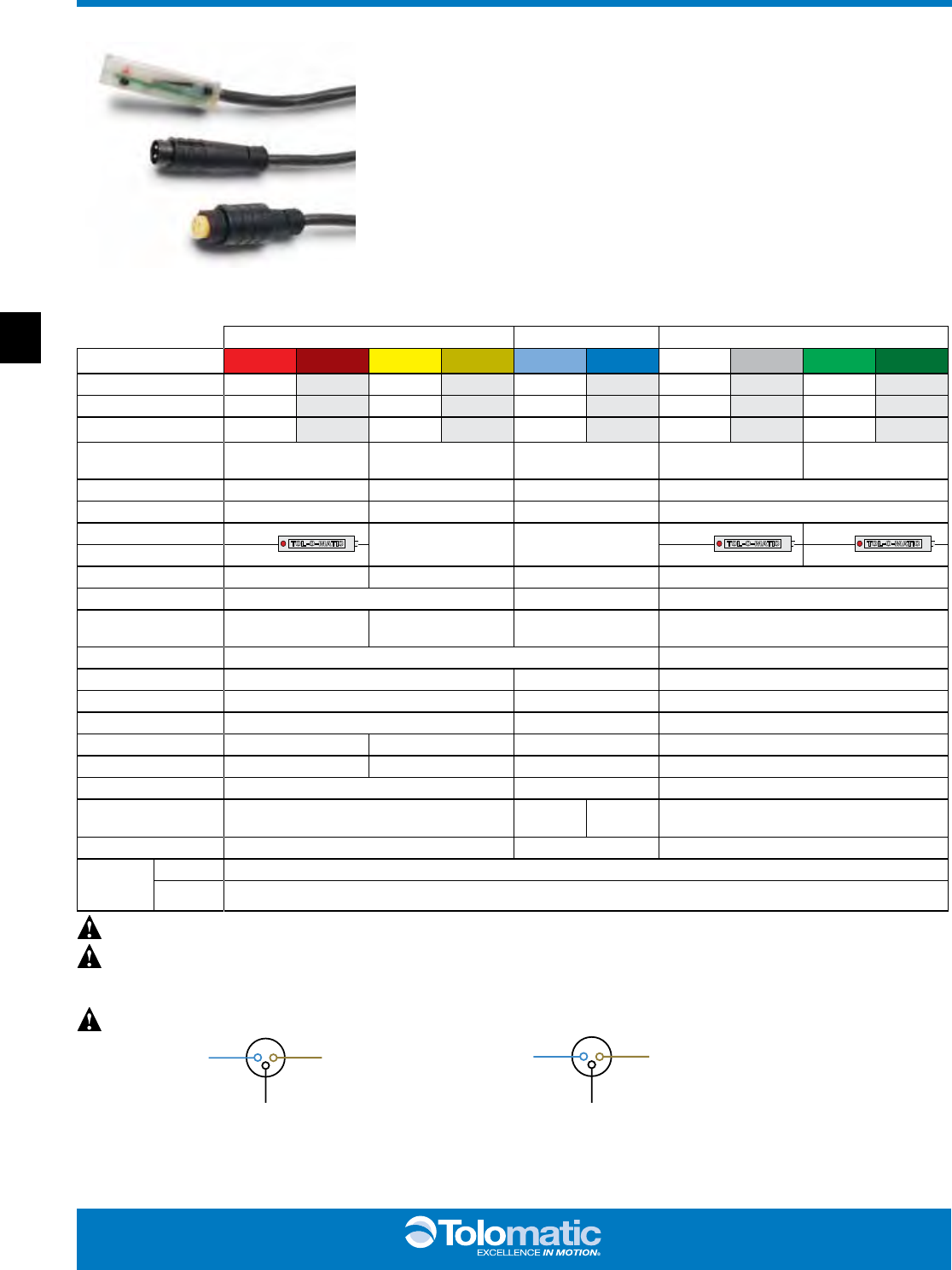
SPECIFICATIONS
REED DC REED AC HALL-EFFECT DC
ORDER CODE
R T R M B T B M C T C M T T T M K T K M
PART NUMBER 3600-9082 3600-9083 3600-9084 3600-9085 3600-9086 3600-9087 3600-9088 3600-9089 3600-9090 3600-9091
LEAD 5m QD* 5m QD* 5m QD* 5m QD* 5m QD*
CABLE SHIELDING Unshielded Shielded† Unshielded Shielded† Unshielded Shielded† Unshielded Shielded† Unshielded Shielded†
SWITCHING LOGIC "A" Normally Open "C" Normally Open or Closed Triac Normally Open PNP (Sourcing) Normally
Open NPN (Sinking) Normally Open
MECHANICAL CONTACTS Single-Pole Single-Throw Single-Pole Double-Throw Single-Pole Single-Throw NO, These Are Solid State Components
COIL DIRECT Yes Yes Yes —
POWER LED None None None None None
SIGNAL LED Red Red Red
OPERATING VOLTAGE 200 Vdc max. 120 Vdc max. 120 Vac max. 5 - 25 Vdc
OUTPUT RATING — — 25 Vdc, 200mA dc
OPERATING TIME 0.6 msec max.
(including bounce)
0.7 msec max.
(including bounce) — < 10 micro sec.
OPERATING TEMPERATURE -40°F [-40°C] to 158°F [70°C] 0°F [-18°C] to 150°F [66°C]
RELEASE TIME 1.0 msec. max. — —
ON TRIP POINT — — 150 Gauss maximum
OFF TRIP POINT — — 40 Gauss minimum
**POWER RATING (WATTS) 10.0
§
3.0
§ §
10.0 5.0
VOLTAGE DROP 2.6 V typical at 100 mA NA — —
RESISTANCE 0.1 Ω Initial (Max.) — —
CURRENT CONSUMPTION —1 Amp at
86°F [30°C]
0.5 Amp at
140°F [60°C] 200 mA at 25 Vdc
FREQUENCY — 47 - 63 Hz —
CABLE MIN.
BEND
RADIUS
STATIC 0.630" [16mm]
DYNAMIC Not Recommended
ABT MXP BC2 BC3 BC4 LS MG CC PB ENGR
2020
www.tolomatic.com
BC2_21
BC2 Switches - ALL Sizes
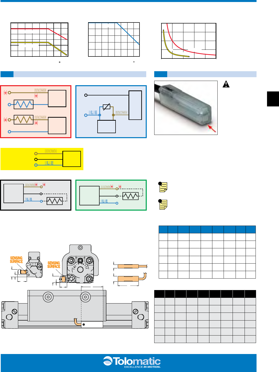
PERFORMANCE
THE NOTCHED
FACE OF THE
SWITCH INDICATES
THE SENSING
SURFACE AND
MUST FACE
TOWARD THE
MAGNET.
THE NOTCHED
GROOVE IN THE
ACTUATOR
INDICATES THE
GROOVE TO
INSTALL THE
SWITCH. CONTACT
TOLOMATIC IF
SWITCHES ARE
REQUIRED ON
ANOTHER SIDE OF
ACTUATOR.
0
50
100
150
200
0 100 200 300 400 500
VOLTAGE A.C. or D.C.
CURRENT D.C (mA)
REED FORM A
R
E
E
D
F
O
R
M
C
TEMP. vs CURRENT, DC REED VOLTAGE DERATING, DC REEDTEMP. vs CURRENT, AC REED
0
100
200
300
400
500
600
0 20 40 60 80 100 120 140 160
LOAD CURRENT (mA)
OPERATING TEMPERATURE ( F)
REED FORM C
REED FORM A
0
200
400
600
800
1000
0 20 40 60 80 100 120 140 160
LOAD CURENT (mA)
OPERATING TEMPERATURE ( F)
TRIAC
R T & R M DC REED, FORM A
B T & B M DC REED, FORM C
C T & C M AC REED, TRIAC
T T & T M HALL-EFFECT, SOURCING, PNP
K T & K M HALL-EFFECT, SINKING, NPN
REED
SWITCH
LOAD
BROWN
BLUE
(-) (-)
(+) (+)
REED
SWITCH
LOAD
BROWN
BLUE
(-) (-)
(+) (+)
OR
AC
COM
LOAD
INPUT
TRIAC
SWITCH
120Vac
Max.
MOV
BROWN
BLUE
REED
SWITCH
COMMON
NORMALLY CLOSED
NORMALLY OPEN
BROWN
BLACK
BLUE
HALL-EFFECT
SOURCING
SWITCH
BLACK
LOAD
BROWN
BLUE (-)
(+)
(-)
(+)
HALL-EFFECT
SINKING
SWITCH
BROWN
BLACK
BLUE (-)
(+)
(-)
(+)
LOAD
WIRING DIAGRAMS INSTALLATION INFORMATION
F
G
BCA
BC
BC205
BC210, BC212, BC215
BC215, BC220, BC225
SWITCH DIMENSIONS
A
D
E
SIZE
BORE
A B C D E F G
05 0.50 0.445 0.157 0.518 0.219 0.315 1.25 1.45
10 1.00 0.383 0.011 0.448 0.219 0.315 1.25 1.45
12 1.25 0.541 0.169 0.448 0.219 0.315 1.25 1.45
15 1.50 0.548 0.161 0.432 0.219 0.315 1.25 1.45
20 2.00 0.732 0.344 0.448 0.219 0.315 1.25 1.45
25 2.50 1.082 0.710 0.432 0.219 0.315 1.25 1.45
Dimensions in inches
SIZE
BORE
A B C D E F G
M05 12 11.30 3.99 13.16 5.56 8.00 31.75 36.83
M10 25 9.73 0.28 11.38 5.56 8.00 31.75 36.83
M12 32 13.74 4.29 11.38 5.56 8.00 31.75 36.83
M15 40 13.92 4.09 10.97 5.56 8.00 31.75 36.83
M20 50 18.59 8.74 11.38 5.56 8.00 31.75 36.83
M25 63 27.48 18.03 10.97 5.56 8.00 31.75 36.83
Dimensions in millimeters
DIMENSIONS
HALL-EFFECT SWITCHES ARE NOT
AVAILABLE FOR BC205
Some actuators may require switch mounting
on a specific side of the assembly.
Call Tolomatic for details.
ENGR PB CC MG LS BC4 BC3 BC2 MXP ABT
2121
BC2_22 1.800.328.2174
B
A
C
D
EA
B
C
F
G
C
L
SIZE
BORE
A B C (Thread Size)
10 1.00 2.35 2.50 9/16-18 UNF-2B
12 1.25 2.23 3.50 3/4-16 UNF-2B
15 1.50 2.23 4.00 3/4-16 UNF-2B
20 2.00 2.62 4.70 1-12 UNF-2B
25 2.50 1.17 6.00 1-12 UNF-2B
Dimensions in inches
SIZE
BORE
A B C (Thread Size) D E F G
10 1.00 3.68 2.45 9/16-18 UNF-2B 2.00 0.15 2.59 0.21
12 1.25 4.39 3.19 3/4-16 UNF-2B 2.25 0.13 2.82 0
15 1.50 4.39 3.62 3/4-16 UNF-2B 2.50 0.05 3.50 0
20 2.00 4.75 4.60 1-12 UNF-2B 3.13 0.16 4.44 0
25 2.50 4.75 5.63 1-12 UNF-2B 4.47 0.17 5.63 0
Dimensions in inches
SIZE
BORE
A B C (Thread Size)
M10 25 59.7 63.5 M14x1.5-6g
M12 32 56.6 88.9 M20x1.5-6g
M15 40 56.6 101.6 M20x1.5-6g
M20 50 66.5 119.4 M25x1.5-6g
M25 63 29.7 152.4 M25x1.5-6g
Dimensions in millimeters
SIZE
BORE
A B C (Thread Size) D E F G
M10 25 93.5 62.2 M14x1.5-6g 50.8 3.8 65.8 5.3
M12 32 111.5 81.0 M20x1.5-6g 57.2 3.3 71.6 0
M15 40 111.5 92.0 M20x1.5-6g 63.5 1.3 88.9 0
M20 50 120.7 116.8 M25x1.5-6g 79.5 4.1 112.8 0
M25 63 120.7 143.0 M25x1.5-6g 113.5 4.3 143.0 0
Dimensions in millimeters
BC2 Shock Absorbers - 10, 12, 15, 20, 25 Sizes
Rodless cylinders with standard internal cushion
offer an effective method of decelerating loads.
However, all Tolomatic rodless cylinders are capable
of carrying heavier loads at higher velocities than
the cylinder cushion can absorb. Optional shock
absorbers can be used to increase the cylinder’s life
and broaden the application range for the cylinder
model you have chosen.
Tolomatic offers two types of shock absorber
options for use with rodless cylinders. Standard
shock absorbers, which are positioned on the
cylinder heads for end-of-stroke deceleration and
adjustable shock absorbers which allows the shock
to be positioned at any point along the cylinder.
Typical shock absorber life varies between 1-2 million cycles (depending on environment) appropriate preventative maintenance
should be consid ered in high cyclic applications.
NOTE: When 2 shock absorbers are ordered, the unit will be assembled with NO internal cushions.
NOTE: Adjustable shock absorbers will reduce stroke length. To maintain desired stroke length: when ordering increase
stroke length by the dimension in the table below for each adjustable shock absorber ordered.
10 12 15 20 25
0.75" [19.0mm] 0.03" [0.7mm] 0.35" [8.9mm] 0.85" [21.6mm] 0.85" [21.6mm]
CAUTION: In applications which result in a load bending moment at deceleration, care should be taken to decelerate the
load rather than the carrier of the band cylinder.
SHOCK ABSORBERS
ORDER CODE
SD_ or SH_ or SL_
(_ = Number ordered)
ORDER CODE
AD_ or AH_ or AL_
(_ = Number ordered)
STANDARD SHOCK ADJUSTABLE POSITION SHOCK
DIMENSIONS
3d cad available at
www.tolomatic.com
ABT MXP BC2 BC3 BC4 LS MG CC PB ENGR
2222
www.tolomatic.com
BC2_23
BC210
BC215
BC225
BC212
BC220
BC2 Shock Absorbers - 10, 12, 15, 20, 25 Sizes: PERFORMANCE
VELOCITY vs LOAD
LOAD (lbs)
FINAL VELOCITY (in/sec)
FINAL VELOCITY (meters/sec)
2.5 2.3
2.0 1.8
1.5 1.3
1.0
.8
.5
.25
.23 .20
.18 .15
.13 .10
.08
.05
.03
100 90
80 70
60 50
40
30
20
10 9
87
65
4
3
2
1
1
2
3
4
5
6
7
8
9
10
20
30
40
50
60
70
80
90
100
.5
.9
1.4
1.8
2.7 3.2
3.6 4.1
4.5
9.1
13.6
18.1
22.7 27.2
31.7 36.3
40.8 45.4
2.3
LOAD (kg)
12345678910 20 30 405060
70
80
90
100 200
1
2
3
4
56
78
910
20
30
40 50
60 70
80 90
100
200
LOAD (lbs)
FINAL VELOCITY (in/sec)
FINAL VELOCITY (meters/sec)
2.5
2.3 2.0
1.8 1.5
1.3 1.0
.8
.5
.3 .23
.20 .18
.15 .13
.10
.08
.05
.03
.5
.9
1.4
1.8
2.7 3.2
3.6 4.1
4.5
9.1
13.6 18.1
22.7 27.2
31.7 36.3
40.8 45.4
2.3
LOAD (kg)
90.7
5.1
12345678910 20 30 405060
70
80
90
100 200
1
2
3
4
56
78
910
20
30
40 50
60 70
80 90
100
200
LOAD (lbs)
2.5
2.3 2.0
1.8 1.5
1.3 1.0
.8
.5
.25 .23
.20 .18
.15 .13
.10
.08
.05
.03
.5
.9
1.4
1.8
2.7 3.2
3.6 4.1
4.5
9.1
13.6
18.1
22.7 27.2
31.7 36.3
40.8 45.4
2.3
LOAD (kg)
90.7
5.1
FINAL VELOCITY (in/sec)
FINAL VELOCITY (meters/sec)
LOAD (lbs)
FINAL VELOCITY (in/sec)
FINAL VELOCITY (meters/sec)
LOAD (kg)
30
40 50
60 70
80 90
100
200
1
2
34
56
78
910
20
.5
1.4
3.2
4.1
9.1
18.1
27.2
36.3
45.4
2.3
136.1
.9
1.8
2.7
3.6
4.5
13.6
22.7
31.7
40.8
90.7
2.5
2.0
1.5
1.0
.50
.23
.18
.13
.08
.03
2.3
1.8
1.3
.80
.25
.20
.15
.10
.05
5.1
1 3 5 7 9 20 40 60 80100 300
2 4 6 8 10 30 50 70 90 200
LOAD (lbs)
FINAL VELOCITY (in/sec)
FINAL VELOCITY (meters/sec)
LOAD (kg)
.5
1.4
3.2
4.1
9.1
18.1
27.2
36.3
45.4
2.3
136.1
226.8
.9
1.8
2.7
3.6
4.5
13.6
22.7
31.7
40.8
90.7
181.4
2.5
2.0
1.5
1.0
.50
.23
.18
.13
.08
.03
2.3
1.8
1.3
.80
.25
.20
.15
.10
.05
5.1
1 3 5 7 9 20 40 60 80100 300 500
2 4 6 8 10 30 50 70 90 200 400
40
60
80
100
1
3
5
7
9
20
30
50
70
90
200
2
4
6
8
10
LIGHT DUTY (Light load/High velocity)
HEAVY DUTY (Heavy load/Low velocity)
AIR CUSHION DATA
NOTE: If final (or impact) velocity cannot be calculated
directly, a reasonable guideline to use is 2 x average velocity.
ENGR PB CC MG LS BC4 BC3 BC2 MXP ABT
2323
BC2_24 1.800.328.2174
Application Data Worksheet
STROKE LENGTH _____________
inch (SK) millimeters
(U.S. Standard) (Metric)
AVAILABLE AIR PRESSURE _____
PSI bar
(U.S. Standard) (Metric)
REQUIRED THRUST FORCE _____
lbf N
(U.S. Standard) (Metric)
LOAD _________________
_
____
lb kg
(U.S. Standard) (Metric)
LOAD CENTER OF
dx
______
GRAVITY DISTANCE
dy
______
TO CARRIER CENTER
dz
______
inch millimeters
(U.S. Standard) (Metric)
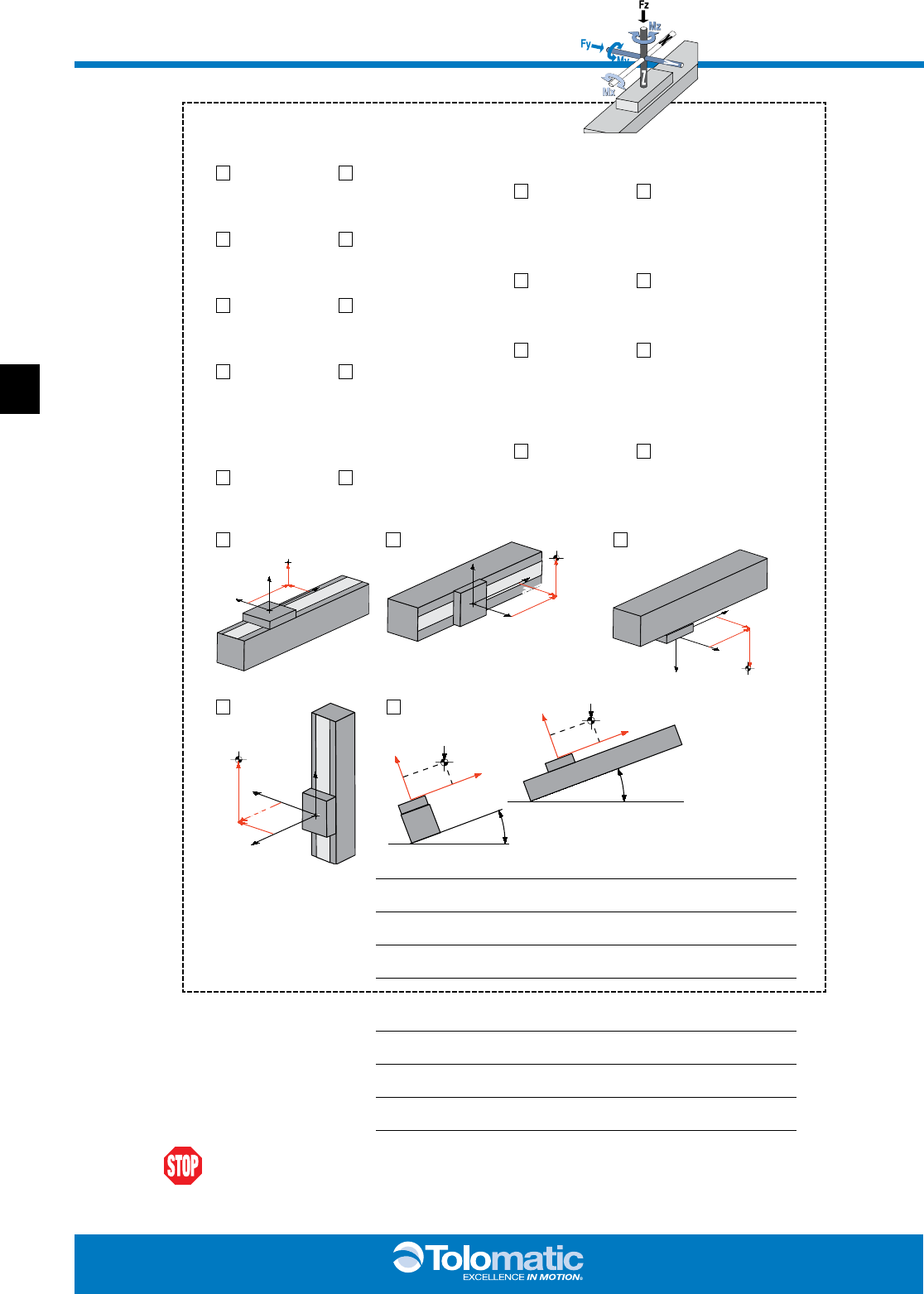
ORIENTATION
FRONT
VIEW
β
Lz
X
Z
SIDE VIEW
α
Lz
Y
Z
ACTUATOR
ACTUATOR
CARRIER
CARRIER
CENTER
OF GRAVITY
dz
d
Y
dx
CENTER
OF GRAVITY
dz
d
Y
dx
ACTUATOR
ACTUATOR
CARRIER
CARRIER
ACTUATOR
ACTUATOR
CARRIER
CARRIER
CENTER
OF GRAVITY
dy
dZ
dy
dZ
dx
dx
CENTER
OF GRAVITY
CARRIER
ACTUATOR
CARRIER
ACTUATOR
dz
dz
dY
FORCES APPLIED
Fz
______
TO CARRIER
Fy
______
lbf N
(U.S. Standard) (Metric)
BENDING MOMENTS
Mx
______
APPLIED TO CARRIER
My
______
in-lbs N-m Mz
______
(U.S. Standard) (Metric)
FINAL VELOCITY _____________
in/sec mm/sec
(U.S. Standard) (Metric)
MOVE TIME
sec.
_____________
NO. OF CYCLES _____________
per minute per hour
Horizontal Side Horizontal Down
Vertical Angled α __________ β
____________
Fax (1-763-478-8080) or call Tolomatic (1-800-328-2174) with the above information.
We will provide any assistance needed to determine the proper actuator.
OTHER ISSUES:
(i.e. Environment,
Temperature,
Contamination, etc.)
Contact information:
ABT MXP BC2 BC3 BC4 LS MG CC PB ENGR
2424

www.tolomatic.com
BC2_25
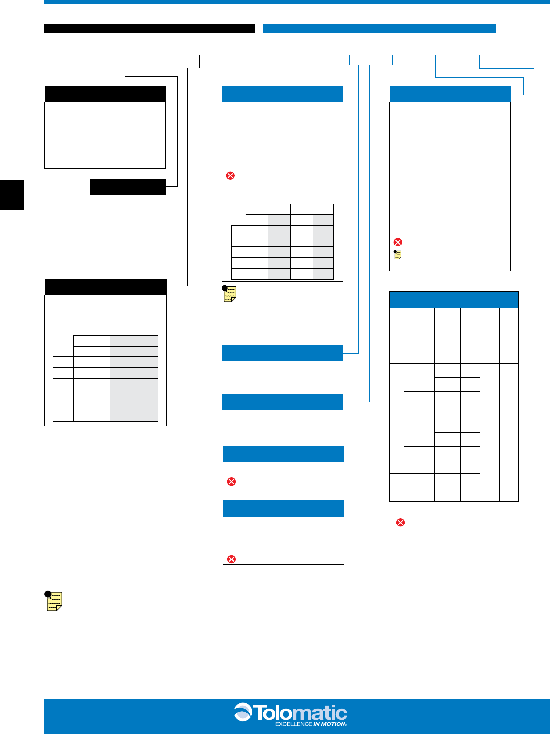
Rodless Cylinder Selection Guidelines
- BC2, BC3, BC4, LS - All Sizes
PROVIDING LOAD GUIDANCE AND SUPPORT
The process of selecting
a load bearing actuator
for a given application can
be complex. It is highly
recommended that you
contact Tolomatic or a
Tolomatic Distributor for
assistance in selecting
the best actuator for your
application. The following
overview of the selection
guidelines are for educa-
tional purposes only.
1 COMPILE
APPLICATION
REQUIREMENTS
To determine the appropriate
Band Cylinder or Linear Slide
model for an application, compile
the following information:
• Available pressure (PSI)
• Weight of load (lbs or kg)
• Orientation of load (lbs or kgs)
• Velocity of load (in/sec or
mm/sec)
• Stroke length (in or mm)
HINT: Use Tolomatic sizing and
selection software, download at:
tolomatic.com
2
SELECT
CYLINDER SIZE
• Consult the Theoretical Force
vs. Pressure charts.
• Cross-reference the load force
(or load weight if force is not
known) and the available
operating pressure. If the
intersection falls below the
diagonal line, and if moments
do not exceed maximum
values listed for that model
(see Step 3), the actuator will
accommodate the application.
If the intersection is above the
diagonal line, a larger cylinder
bore size should be
considered.
NOTE: Additional force may be
required to obtain the necessary
acceleration for vertical or
horizontal loads.
3 DETERMINE
NATURE OF
LOAD AND THE
EFFECT OF
BENDING
MOMENTS
If the cylinder will guide and
support a load located directly
over the center of carrier, bending
moments will not be a factor in
the cylinder selection.
NOTE: The maximum load “L”
must not exceed the capacity
limits of the cylinder selected.
• Bending Moments
For off center or side loads,
determine the distance from
the center of mass of the load
to the center of the carrier
bracket. This measurement is
needed to calculate the torque
for bending moments. (Refer to
Bend ing Moment chart for
each model.)
Should the resulting maximum
bending moment exceed
figures indicated on the chart,
external guides, auxiliary
carrier/s or a larger cylinder
should be considered.
• Auxiliary Carrier Bending
Moments
The auxiliary carrier option
(available on most models)
increases load carrying
capacity and bending
moments. Auxiliary carriers
can be ordered with or without
an internal piston. (Auxiliary
carriers without a piston have
no internal cushion on the
cylinder end closest to the
auxiliary carrier.)
IMPORTANT: When ordering,
determine the working stroke,
then the minimum distance
required between carriers
(dimension “D” in Auxiliary
Carrier Bending Mom ents
chart). When ordered,
Tolomatic’s configurator will
calculate the overall length of
the actuator.
NOTE: breakaway pressure will
increase when using auxiliary
carriers.
4 DETERMINE
INTERNAL
CUSHION
CAPACITY
• Consult the Cushion Data chart
for the model selected. The
velocities listed on the cushion
charts are final or cushion
impact velocities. On
applications where the internal
cushions or bumpers are to be
used, be sure the actual, final
or impact velocity is known. If
the velocity is not known, use
of limit switches with valve
deceleration circuits or shock
absorbers should be
considered. NOTE: The BC205
uses external bumpers in place
of internal cushions, LS05 &
LS10 do not have cushions or
bumpers.
• Cross-reference the final
velocity and weight of the load.
If the intersection is below the
diagonal lines, the internal
cushions on the actuator may
be used. If the point falls above
the dashed diagonal line or if
the velocity is not known, use
deceleration circuits, external
shock absorbers or select a
larger cylinder with greater
cushion capacity. On high-
cyclic applications, use of
external stops is strongly
recommended.
5 DETERMINE
TUBE SUPPORT
REQUIREMENTS
• Consult the Tube Support chart
for the model selected.
• Cross reference the load
weight and maximum distance
between supports.
6
CONSIDER
OPTIONS
• Switches– dc Reed, Hall-effect
or ac Triac
Band Cylinders and Linear Slides
each have different standard
features and options. Check the
options section for the actuator
you have selected.
• Shock Absorbers– if needed.
• Foot Mounting Kits
• Floating Mount Bracket – use
when lack of parallelism
occurs between the cylinder
and an external guided and
supported load.
• Single End Porting (BC3, BC4)
• Long Carrier (BC4)
• Proximity Sensors (LS)
• Dual 180° Carrier (BC3)
ENGR PB CC MG LS BC4 BC3 BC2 MXP ABT
2525
BC2_26 1.800.328.2174
Application Guidelines
The following conditional
statements are intended as
general guidelines for use of
Tolomatic actuators. Since all
applications have their own
specific operating
requirements, consult
Tolomatic, Inc. or your local
Tolomatic distributor if an
application is unconventional
or if questions arise regarding
the selection process.
CUSHION NEEDLE
ADJUSTMENT (BC2,
BC3, BC4, CC, SA, DP,
TC ONLY)
Adjust the cushion needles in
the cylinder heads carefully to
obtain a smooth, hesitation
free deceleration for your
particular application. If there
are questions on proper
adjustment, please consult
Tolomatic, Inc.
LUBRICATION
GUIDELINES
All Tolomatic actuators (except
Cable Cylinders) are
prelubricated at the factory. To
ensure maximum actuator life,
the following guidelines should
be followed.
• Filtration
We recommend the use of
dry, filtered air in our
products. “Filtered air”
means a level of 10 Micron
or less. “Dry” means air
should be free of
appreciable amounts of
moisture. Regular
maintenance of installed
filters will generally keep
excess moisture in check.
• External Lubricators
(optional)
The factory prelubrication of
Tolomatic actuators will
provide optimal
performance without the
use of external lubrication.
However, external
lubricators can further
extend service life of
pneumatic actuators if the
supply is kept constant.
Oil lubricators, (mist or drop)
should supply a minimum of
1 drop per 20 standard
cubic feet per minute to the
cylinder. As a rule of thumb,
double that rate if water in
the system is suspected.
Demanding conditions may
require more lubricant.
If lubricators are used, we
recommend a non-
detergent, 20cP @ 140˚F
10-weight lubricant.
Optimum conditions for
standard cylinder operation
are +32˚ to +150˚F (+0˚ to
65.5˚C).
NOTE: Use of external
lubricators may wash away
the factory installed
lubrication. External
lubricants must be
maintained in a constant
supply or the results will be
a dry actuator prone to
premature wear.
• Sanitary Environments
Oil mist lubricators must
dispense “Food Grade”
lubricants to the air supply.
Use fluids with ORAL LD50
toxicity ratings of 35 or
higher such as Multitherm®
PG-1 or equivalent.
Demanding conditions can
require a review of the
application.
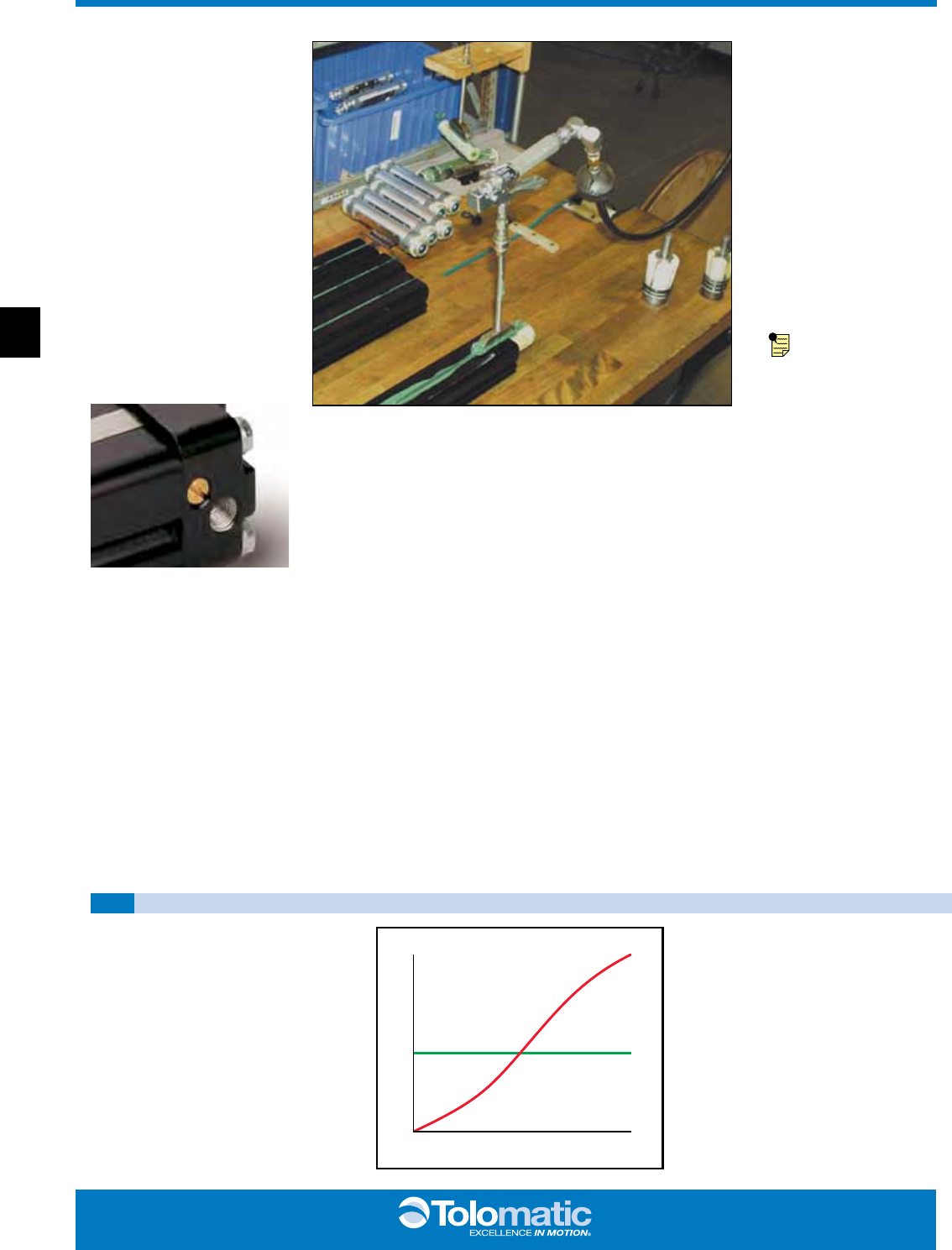
Velocity calculations for all rodless
cylinders need to differentiate between
final velocity and average velocity. For
example: Stroking a 100-inch BC3 model
in one second yields an average velocity
of 100 inches per second. To properly
determine the inertial forces for
cushioning, it is important to know the
final (or impact) velocity. Rodless cylinders
accelerate and decelerate at each end of
the stroke. Therefore this acceleration
must be considered (see diagram).
If final (or impact) velocity cannot be
calculated directly, a reasonable guideline
is to use 2 x average velocity.
FINAL VELOCITY CALCULATION
VELOCITY
Start Time End
Final (impact)
Average
ABT MXP BC2 BC3 BC4 LS MG CC PB ENGR
2626

www.tolomatic.com
BC2_27
Application Guidelines
The following conditional
statements are intended as
general guidelines for use of
Tolomatic actuators. Since all
applications have their own
specific operating
requirements, consult
Tolomatic, Inc. or your local
Tolomatic distributor if an
application is unconventional
or if questions arise regarding
the selection process.
CUSHION NEEDLE
ADJUSTMENT (BC2,
BC3, BC4, CC, SA, DP,
TC ONLY)
Adjust the cushion needles in
the cylinder heads carefully to
obtain a smooth, hesitation
free deceleration for your
particular application. If there
are questions on proper
adjustment, please consult
Tolomatic, Inc.
LUBRICATION
GUIDELINES
All Tolomatic actuators (except
Cable Cylinders) are
prelubricated at the factory. To
ensure maximum actuator life,
the following guidelines should
be followed.
We recommend the use of
dry, filtered air in our
products. “Filtered air”
means a level of 10 Micron
or less. “Dry” means air
should be free of
appreciable amounts of
moisture. Regular
maintenance of installed
filters will generally keep
excess moisture in check.
(optional)
The factory prelubrica tion of
Tolomatic actuators will
provide optimal
performance without the
use of external lubrication.
However, external
lubricators can further
extend service life of
pneumatic actuators if the
supply is kept constant.
Oil lubricators, (mist or drop)
should supply a minimum of
1 drop per 20 standard
cubic feet per minute to the
cylinder. As a rule of thumb,
double that rate if water in
the system is suspected.
Demanding conditions may
require more lubricant.
If lubricators are used, we
recommend a non-
detergent, 20cP @ 140˚F
10-weight lubricant.
Optimum conditions for
standard cylinder operation
are +32˚ to +150˚F (+0˚ to
65.5˚C).
NOTE: Use of external
lubricators may wash away
the factory installed
lubrication. External
lubricants must be
maintained in a constant
supply or the results will be
a dry actuator prone to
premature wear.
Oil mist lubricators must
dispense “Food Grade”
lubricants to the air supply.
Use fluids with ORAL LD50
toxicity ratings of 35 or
higher such as Multitherm®
PG-1 or equivalent.
Demanding conditions can
require a review of the
application.
Velocity calculations for all rodless
cylinders need to differentiate between
final velocity and average velocity. For
example: Stroking a 100-inch BC3 model
in one second yields an average velocity
of 100 inches per second. To properly
determine the inertial forces for
cushioning, it is important to know the
final (or impact) velocity. Rodless cylinders
accelerate and decelerate at each end of
the stroke. Therefore this acceleration
must be considered (see diagram).
If final (or impact) velocity cannot be
calculated directly, a reasonable guideline
is to use 2 x average velocity.
VELOCITY
StartTime End
Final (impact)
Average
- ALL Sizes
Service Parts Ordering NOTES:
1Foot Mount Kit contains two foot mount brackets and mounting
hardware
2Shock Field Retrofit Kit contains one Shock Absorber and mount-
ing hardware
3Shock Field Mount Kit contains one set of mounting hardware
only
4A minimum of 2 (two) Tube Supports required per cylinder
5Repair Kit for 05 size contains O-rings, U-Cups, End Caps, Wear
Strips, Band Inserts, Spring Clamps, Sealing Band, Dust Band and
Shock Absorbing Pads
6Repair Kit for 10, 12, 15, 20 & 25 size contains End Caps, Bearing
Rods, O-rings, U-cups, Wear Rings, Cushion Seals, Band Inserts,
Spring Clamps, Sealing Band and Dust Band.
7When ordering repair kits, specify stroke as “SK” then indicate
the desired length in decimal inches after the order code indi-
cated above. EXAMPLE: RKBC210SK10.00
8Standard end-of-stroke shock absorbers are designed to operate
without the assistance of the standard band cylinder cushion. To
ensure proper shock absorber performance, make sure the air
cushion is disabled.
NA = Not Available
Switch Ordering NOTES:
To order field retrofit switch and hardware kits for all Tolo-
matic actuators: SW (Then the model and bore size, and type
of switch required)
(Hardware and Form A Reed switch with 5 meter lead for 1.5"
bore BC2 band cylinder)
Mounting hardware is required if replacing switch for any
actuator manufactured before 7/1/97
PART NUMBER ORDERING
DESCRIPTION CODE
3600-9084
Switch Only, Reed, Form C, 5m
BT
3600-9085
Switch Only, Reed, Form C, Male Conn.
BM
3600-9082
Switch Only, Reed, Form A, 5m
RT
3600-9083
Switch Only, Reed, Form A, Male Conn.
RM
3600-9086
Switch Only, Triac, 5m
CT
3600-9087
Switch Only, Triac, Male Conn.
CM
3600-9090
Switch Only, Hall-effect, Sinking, 5m
KT
3600-9091
Switch Only, Hall-effect, Sinking, Male Conn.
KM
3600-9088
Switch Only, Hall-effect, Sourcing, 5m
TT
3600-9089
Switch Only, Hall-effect, Sourcing, Male Conn.
TM
2503-1025
Connector (Female) 5 meter lead
NOTE: When ordered by Config. Code Female connector & all mounting hardware is included
05 10 12 15 20 25
NA 0510-9057 0512-9057 0515-9057 0520-9057 0525-9057
NA 0510-9095 0512-9095 0515-9095 0520-9095 0525-9095
0905-9115 0510-9007 0512-9007 0515-9007 0520-9007 0525-9007
10905-9010 0510-9125 0512-9125 0515-9125 0520-9125 0525-9125
2,8 NA 0510-9090 0512-9090 0515-9090 0520-9090 0525-9090
2,8 NA 0510-9091 0512-9091 0515-9091 0520-9091 0525-9091
3,8 NA 0510-9092 0512-9092 0515-9092 0520-9092 0525-9092
2NA 0510-9048 0512-9011 0515-9011 0520-9011 0525-9011
2NA 0510-9049 0512-9012 0515-9012 0520-9012 0525-9012
3NA 0510-9072 0512-9072 0515-9072 0520-9072 0525-9013
40905-1034 4510-1010 4512-1010 4515-1010 4520-1010 4525-1010
0505-9999 0510-9999 0512-9999 0515-9999 0520-9999 0525-9999
5,6,7 RKBC205 RKBC210 RKBC212 RKBC215 RKBC220 RKBC225
M(MM)05 M(MM)10 M(MM)12 M(MM)15 M(MM)20 M(MM)25
NA 4510-9057 4512-9057 4515-9057 4520-9057 4525-9057
NA 4510-9095 4512-9095 4515-9095 4520-9095 4525-9095
4905-9115 4510-9007 4512-9007 4515-9007 4520-9007 4525-9007
14905-9010 4510-9125 4512-9125 4515-9125 4520-9125 4525-9125
2,8 NA 4510-9090 4512-9090 4515-9090 4520-9090 4525-9090
2,8 NA 4510-9091 4512-9091 4515-9091 4520-9091 4525-9091
3,8 NA 4510-9092 4512-9092 4515-9092 4520-9092 4525-9092
2NA 4510-9013 4512-9013 4515-9013 4520-9013 4525-9013
2NA 4510-9014 4512-9014 4515-9014 4520-9014 4525-9014
3NA 4510-9025 4512-9025 4515-9025 4520-9025 4525-9025
40905-1034 4510-1010 4512-1010 4515-1010 4520-1010 4525-1010
0505-9999 0510-9999 0512-9999 0515-9999 0520-9999 0525-9999
5,6,7
RKBC2M(MM)05 RKBC2M(MM)10 RKBC2M(MM)12 RKBC2M(MM)15 RKBC2M(MM)20 RKBC2M(MM)25
ENGR PB CC MG LS BC4 BC3 BC2 MXP ABT
2727
BC2_28 1.800.328.2174
BC2 Ordering - ALL Sizes
TUBE SUPPORTS (BC2_16)
TS_ Tube Support & number
required
FOOT MOUNT (BC2_17)
FM_ Foot Mount & number
required (1 or 2)
PORTING OPTION
HDL 4-Ported Head - Left End
HDR 4-Ported Head - Right End
HDB 4-Ported Head - Both Ends
Not available for 05 size
SHOCK ABSORBERS (BC2_22)
SD_ Shock hardware Only and
number required
SH_ Shock, Heavy duty and
number required
SL_ Shock, Light duty and
number required
*AD_ Adjustable shock hardware
Only and number required
*AH_ Adjustable shock, Heavy
duty and number required
*AL_ Adjustable shock, Light duty
and number required
Not available for 05 size
*NOTE: Adjustable Shock will reduce
working stroke (see page BC2_22)
FLOATING MOUNT (BC2_18)
FL Floating Mount Bracket
Not compatible with shock absorbers
Not all codes listed are compati-
ble with all options. Contact
Tolomatic with any questions.
MODEL, BORE, STROKE OPTIONS
MODEL & MOUNTING
BC2 BC2 Band Cylinder -
inch (U.S. Standard)
BC2M metric mounting with
taper port
BC2MM metric mounting with
parallel port
STROKE LENGTH
SK
_ _._ _
Enter desired stroke length
in decimal inches
MAXIMUM STROKE
SIZE
BC2 BC2M(MM)
in mm
05 171 4,343
10 350 8,890
12 288 7,315
15 298 7,569
20 274 6,959
25 163 4,140
BORE SIZE
05 0.50” (12mm)
10 1.00” (25mm)
12 1.25” (32mm)
15 1.50” (40mm)
20 2.00” (50mm)
25 2.50” (63mm)
BC2__ 10 SK100.250 DW6.0 TS3 FM2 SH2 BM2
AUXILIARY CARRIER (BC2_14)
DW Auxiliary carrier With
piston & “D” distance
DO Auxiliary carrier Without
piston & “D” distance
_ _._ _ “D” Distance between
carriers
Not available for 05 size
MINIMUM “D” DISTANCE
BETWEEN CARRIERS
(DO) w/o Piston (DW) w/ Piston
in mm in mm
10 5.07 129 5.07 129
12 5.17 131 6.85 174
15 6.46 164 8.07 205
20 8.10 206 8.10 206
25 9.62 244 11.06 281
*When ordering auxiliary carrier
option, enter the distance
required between carriers. The
configurator will calculate the overall
length of the actuator.
SWITCHES (BC2_20)
TYPE
QUICK-
DISCONNECT
CODE
QUANTITY
LEAD LENGTH
REED
Form A QD RM
After code enter quantity desired
5 meters
no RT
Form C QD BM
no BT
HALL-EFFECT
Sinking QD *KM
no *KT
Sourcing QD *TM
no *TT
TRIAC QD CM
no CT
MDR
Dual Magnet (Reed, Hall-effect, Triac)
* Not available for 05 size
ABT MXP BC2 BC3 BC4 LS MG CC PB ENGR
2828
