Flowline LRXX Echo Pulse Radar Level Transmitter User Manual
Flowline, Inc. Echo Pulse Radar Level Transmitter
Flowline >
User Manual
Rev9_4
EchoPulse™
RadarLevelTransmitter
LR10,LR15,LR20,LR25&LR30SeriesManual
FlowlineInc.
10500HumboltStreet
LosAlamitos,CA90720
Tel:(562)598‐3015
Fax:(562)431‐8507
www.flowline.com
UNRELEASED

Page2of72MN301700Rev9_4
INTRODUCTIONSectionOne
TableofContentsPage
SectionOne|Introduction:..................................................................................................................................................2
TableofContents:.....................................................................................................................................................2
SensorModels:..........................................................................................................................................................4
OperatingPrinciple:..................................................................................................................................................4
Features:...................................................................................................................................................................4
Benefits:....................................................................................................................................................................4
Limitations:................................................................................................................................................................4
Specifications:...........................................................................................................................................................5
Dimensions:...............................................................................................................................................................8
SafetyPrecautions:.................................................................................................................................................11
SectionTwo|GettingStarted:...........................................................................................................................................12
SetupOverview:......................................................................................................................................................12
PartNumber:...........................................................................................................................................................14
SectionThree|InstallSensor:............................................................................................................................................16
InstallationRequirements:......................................................................................................................................16
LR15AntennaPreparation:.....................................................................................................................................17
MountingPosition:..................................................................................................................................................18
FlangeRiserInstallation:.........................................................................................................................................20
StandPipeInstallation:...........................................................................................................................................22
SightGlassInstallation:...........................................................................................................................................23
LR30SensorInstallation:.........................................................................................................................................24
LR98DisplayInstallation:........................................................................................................................................25
SectionFour|WireSensor:................................................................................................................................................26
TerminalWiring:.....................................................................................................................................................26
LR30SensortoLR98Display:..................................................................................................................................27
WiringtoDisplays,Controllers&PLCs:...................................................................................................................28
SectionFive|Configuration:..............................................................................................................................................30
BasicConfigurationOverview:................................................................................................................................30
UsingtheDisplay:....................................................................................................................................................31
ChangingDisplayValues:........................................................................................................................................32
Step1‐MeasuretheTank:.....................................................................................................................................33
Step2‐SettheUnitsofMeasurement:.................................................................................................................34
Step3‐SettheEmptyConfiguration(4mA):..........................................................................................................35
Step4‐SettheFullConfiguration(20mA):............................................................................................................36
Step5‐SettheRange(MaximumRange):.............................................................................................................37
Step6‐SettheDeadBand:....................................................................................................................................38
Step7‐ChecktheEchoCurve:...............................................................................................................................39
SectionSix|ProcessAdjustments:.....................................................................................................................................40
ProcessAdjustmentsOverview:.............................................................................................................................40
FastFillingorEmptyingofLiquid:...........................................................................................................................41
LiquidSurfaceisTurbulentorAgitated:.................................................................................................................42
FoamontheSurfaceoftheLiquid:.........................................................................................................................43
SensorInstalledinaStandPipeorSightGlass:......................................................................................................44
UNRELEASED

Rev9_4MN301700Page3of72
INTRODUCTIONSectionOne
SectionSeven|AdvancedAdjustments:...........................................................................................................................45
AdvancedAdjustmentsOverview:..........................................................................................................................45
4‐20mAReverseOutput:........................................................................................................................................46
Fail‐SafeOutput:.....................................................................................................................................................47
MinimumCurrentOutput:......................................................................................................................................48
CreateaNewFalseEchoCurve:.............................................................................................................................49
UpdateanExistingFalseEchoCurve:.....................................................................................................................50
SectionEight|Troubleshooting:.........................................................................................................................................51
TroubleshootingOverview:.....................................................................................................................................51
MeasurementStatus:..............................................................................................................................................52
PeakValues:............................................................................................................................................................53
Simulation:..............................................................................................................................................................54
FirstEchoAdjustment:............................................................................................................................................55
EchoCurveZoom:...................................................................................................................................................56
FalseEchoCurveDelete:.........................................................................................................................................57
Reset:......................................................................................................................................................................58
SectionNine|Appendix:.....................................................................................................................................................59
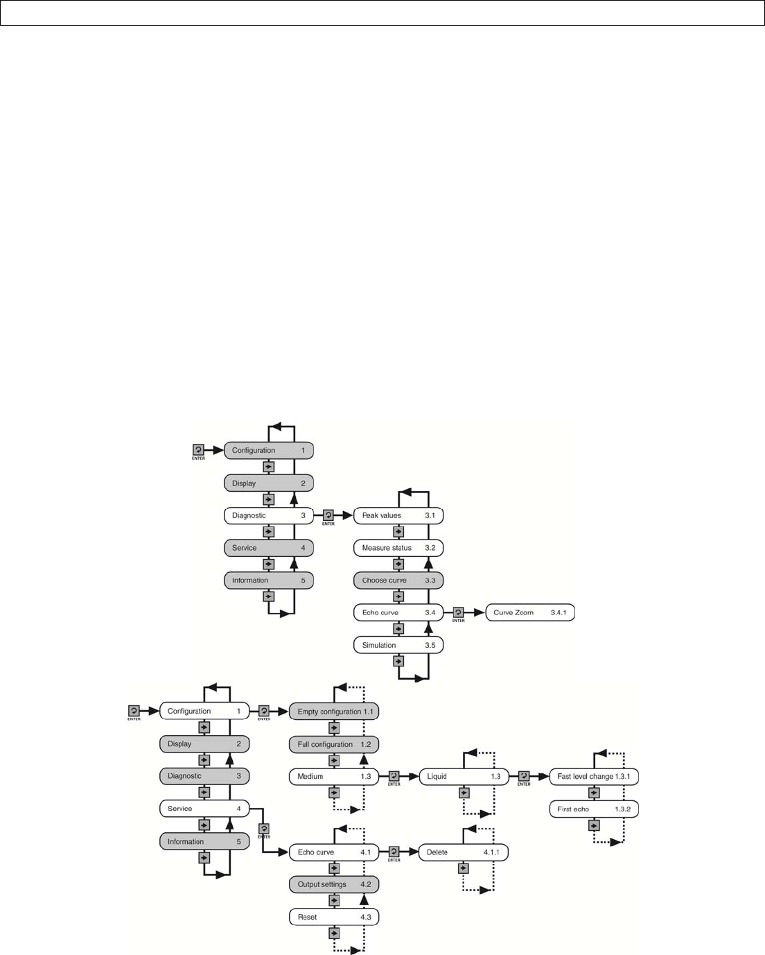
ConfigurationMenu:...............................................................................................................................................59
EmptyConfiguration:..............................................................................................................................................60
FullConfiguration:...................................................................................................................................................60
Medium:..................................................................................................................................................................61
LowDielectricMedium:..........................................................................................................................................62
Dampen:..................................................................................................................................................................63
ScaledUnits:............................................................................................................................................................63
Range:.....................................................................................................................................................................63
DeadBand:..............................................................................................................................................................63
DisplayMenu:.........................................................................................................................................................64
DisplayValue:..........................................................................................................................................................64
LCDContrast:..........................................................................................................................................................64
DiagnosticsMenu:...................................................................................................................................................65
PeakValues:............................................................................................................................................................65
MeasurementStatus:..............................................................................................................................................65
EchoCurve:.............................................................................................................................................................66
Simulation:..............................................................................................................................................................66
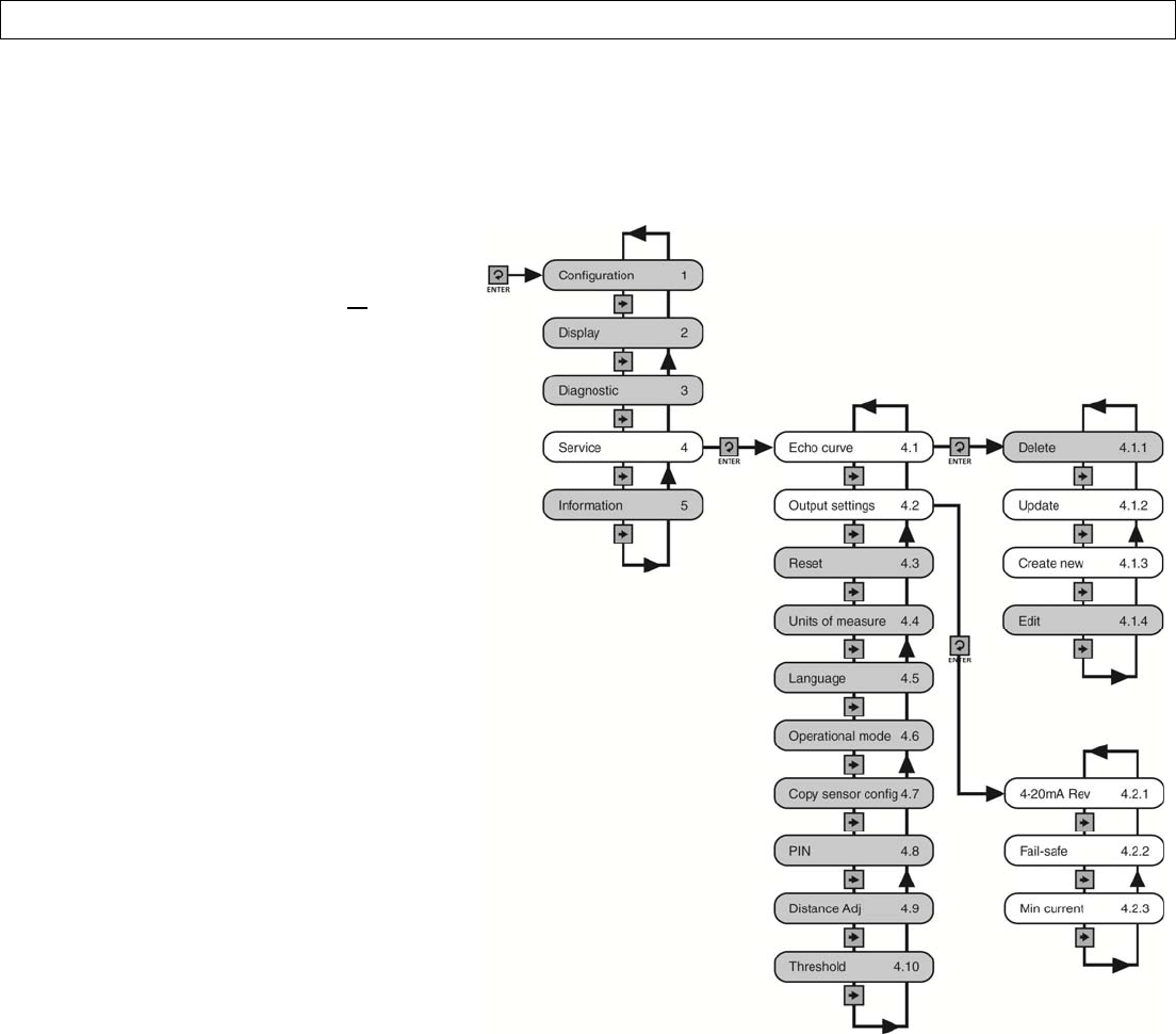
ServiceMenu:.........................................................................................................................................................67
FalseEcho:...............................................................................................................................................................68
OutputSettings:......................................................................................................................................................68
Reset:......................................................................................................................................................................69
UnitsofMeasurement:...........................................................................................................................................69
Language:................................................................................................................................................................69
Information:............................................................................................................................................................70
FactorySettings:......................................................................................................................................................70
UserConfiguration:.................................................................................................................................................70
Notes:......................................................................................................................................................................71
Warranty:................................................................................................................................................................72
UNRELEASED

Page4of72MN301700Rev9_4
INTRODUCTIONSectionOne
SensorModels
Offeredinfivedifferentmodels,EchoPulse™isageneral‐purpose,two‐wire,pulseradarlevelsensorthatprovidesa
continuous4‐20mAcurrentoutputthat’sproportionaltotheliquidlevelinatankorsump.Makesurethatthemodel
purchasedisappropriateforyourapplication.
OperatingPrinciple
Thesensoremitsamicrowavepulsefromitsantenna,whichtravelsatthespeedoflighttothesurfaceofthemedium
below.Aportionofthatenergyreflectsoffthemediumandreturnstotheantenna.Thetimegapbetweenenergy
emissionandreceiptiscalledthe“timeofflight”,andisproportionaltothedistancebetweenthemediumsurfaceand
thesensorsmeasurementlocation,whichistypicallylocatedatthebottomoftheantenna.Thesensormeasuresthe
timeofflightandtranslatesthisvalueintoacontinuous4‐20mAsignaloutputthat’sproportionatetolevelwithina
definedmeasurementspan.
Features
EasyconfigurationwithLCDpushbuttondisplaymodule
Adjustableloopfail‐safe,nochange,20.5mA,22mA
Small12”(30.48cm)deadbandenablesfulltankmeasurement
Recognition,storageanddeletionoffalseechosignalreturns
Benefits
Unaffectedbyphysicalprocessandenvironmentalconditions
Idealforapplicationswithhighertemp,pressure,foamandvapor
Strongsignalpenetrabilitywithminimalattenuationoverdistance
Limitations(factorsthatcouldinfluenceperformance)
Airparticulateswithahighdielectricconstantvaluesuchasleadorferroalloy
Highlydenseairparticulatesthatattenuatemicrowaveemissionandreceipt
Materialbuild‐upontheantennathatdegradesmicrowaveemissionandreceipt
Mediumswithanextremelylowdielectricconstantvaluewithlittlereflectivity
SeriesMaxRangeMaterialMountingApplication
LR1032.81’
(10m)PTFE1‐1/2”NPTCorrosiveliquidsunder
simpleprocessconditions
LR1598.42’
(30m)316LSS
1‐1/2”NPT
3”ANSIflange
4”ANSIflange
6”ANSIflange
Storagetanks&process
tanksunderdifficultprocess
conditions
LR2065.61’
(20m)
316LSSwith
PTFEcover
3”ANSIflange
4”ANSIflange
Aggressiveliquidsunder
extremelydifficultprocess
conditions
LR25114.83’
(35m)
316LSSwith
PTFEcover
4”ANSIflange
6”ANSIflange
Storagetank&processtanks
underextremelydifficult
processconditions
LR3098.42’
(30m)PA66Bracketortop
mounted(1”)conduit
Waterprocessing,lift
stations,stormwaterand
sumpprocessconditions
UNRELEASED

Rev9_4MN301700Page5of72
INTRODUCTIONSectionOne
Specifications
MeasurementRange:
SeriesLR10LR15LR20LR25LR30
Range(Max)32.81ft
(10m)
98.42feet
(30m)
65.61feet
(20m)
114.83feet
(35m)
98.42feet
(30m)
DeadBand:12”(30.48cm)/FactorySet
Note:Canbeloweredto2”fromthebottomoftheantenna
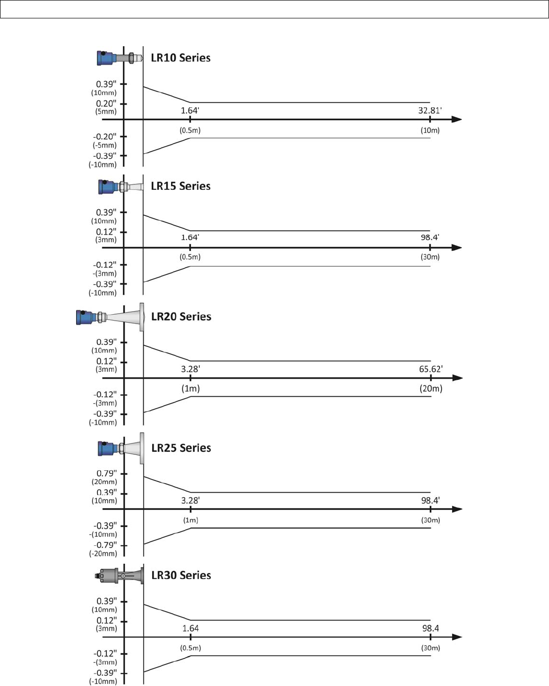
MeasurementAccuracy:(seechartsonPage7)
SeriesLR10LR15LR20LR25LR30
Accuracy±5mm±3mm±3mm±10mm±3mm
DisplayResolution:1mm
FrequencyRange:LR10,LR15,LR20,LR30:......26GHz
LR25:...................................6.3GHz
MeasurementInterval:About1sec(dependentonconfigurationsettings)
AdjustmentTime:About1sec(dependentonconfigurationsettings)
ProcessConnection:Seepartnumberdescription
Material:
SeriesLR10LR15LR20LR25LR30
FlangeN/A316LSSN/A
EnclosureAluminumPA66
AntennaPTFE316LSS316LSSwithPTFECoverPA66
ExtensionPBT‐FRN/A
SealViton
SealRingSilicone(betweenhousingandcap)
WindowPolycarbonateN/A
GroundTerminalStainlessSteel
BracketN/A304SS
Weight:Dependsonprocessconnectionsizeandhousing
SeriesLR10LR15LR20LR25LR30
Weight2.20lbs
(1kg)
4.41lbs
(2kg)
6.61lbs
(3kg)
6.61lbs
(3kg)
2.2lbs
(1kg)
Temperature:
SeriesLR10LR15LR20LR25LR30
Process
Temp
F:‐40°to266°
C:‐40°to130°
F:‐76°to302°
C:‐60°to150°
F:‐40°to302°
C:‐40°to150°
F:‐40°to266°
C:‐40°to130°
F:‐40°to212°
C:‐40°to100°
Storage
Temp
F:‐40°to176°
C:‐40°to80°
RelativeHumidity:<95%
UNRELEASED
Page6of72MN301700Rev9_4
INTRODUCTION SectionOne
ProcessPressure:
SeriesLR10LR15LR20LR25LR30
Pressure‐14.5to43.5psi
(‐1to3bar)
‐14.5to150psi
(‐1to10.3bar)
‐14.5to72.5psi
(‐1to5bar)
‐14.5to580psi
(‐1to40bar)Atmospheric
VibrationProof:Mechanicalvibration10m/s,10m2/s,10‐150Hz
Output:
SignalOutput:4‐20mA
Resolution:1.6µA
Fail‐SafeSetting:20.5mA,22mAornochange
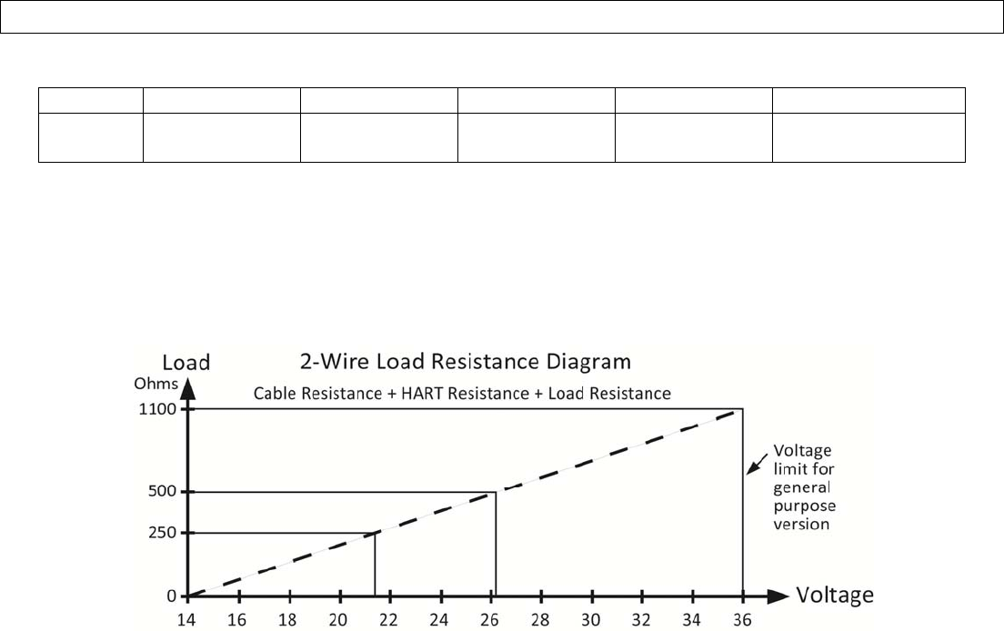
LoadResistance:Seechartbelow
IntegrationTime:0‐40sec,adjustable
Power:
PowerSupply:24VDC(16to26VDC)Thesametwo‐wireconnectioncablecarriespowersupplyand
currentsignal.
PowerConsumption:22.5mAmaximum
RippleAllowed:
<100Hz:<1V
100to100KHz:<10mV
EnclosureRating:LR10,LR15,LR20,LR25:…………IP67(NEMA6)
LR30:………………………………………IP68(NEMA6P)
CableConnection:Standard2‐wireshieldedcablewithearthgroundwireandoutsidediameterof5‐9mm
isrecommended.
CableEntry/Plug:LR10,LR15,LR20,LR25:.............Dualcableentry(½”NPTwithadapter,M20x1.5)
LR30:........................................Onecableentry(1”NPT)
SpringConnectionTerminal:Applicableforcableswithcrosssectionif2.5mm2
Certification:GeneralPurpose:cTUVus(UL61010‐1:2012&CAN/CSA‐C22.2No.61010‐1‐12)
Communication:FCC(US)
Compliance:CE[EN61326(1997w/A1:98,A2:01&A3:03)ClassA]
RoHS
Classification:GeneralPurpose
UNRELEASED
Rev9_4MN301700Page7of72
INTRODUCTIONSectionOne
AccuracyCharts
UNRELEASED
Page8of72MN301700Rev9_4
INTRODUCTIONSectionOne
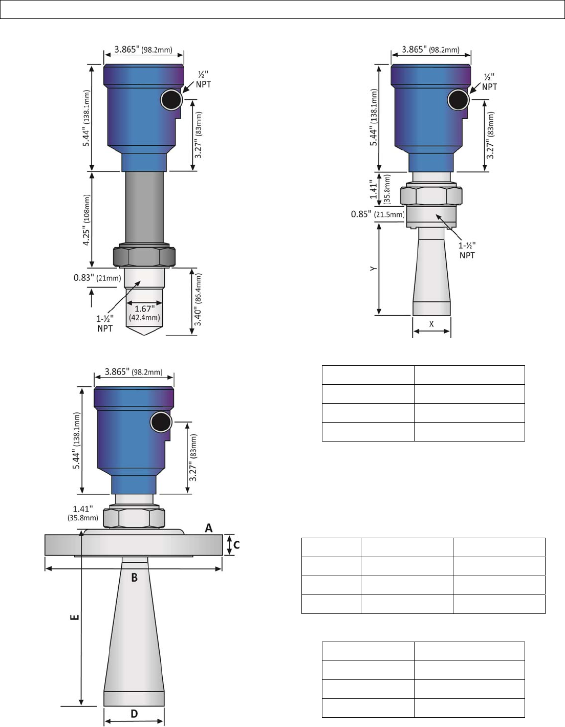
LR10Series
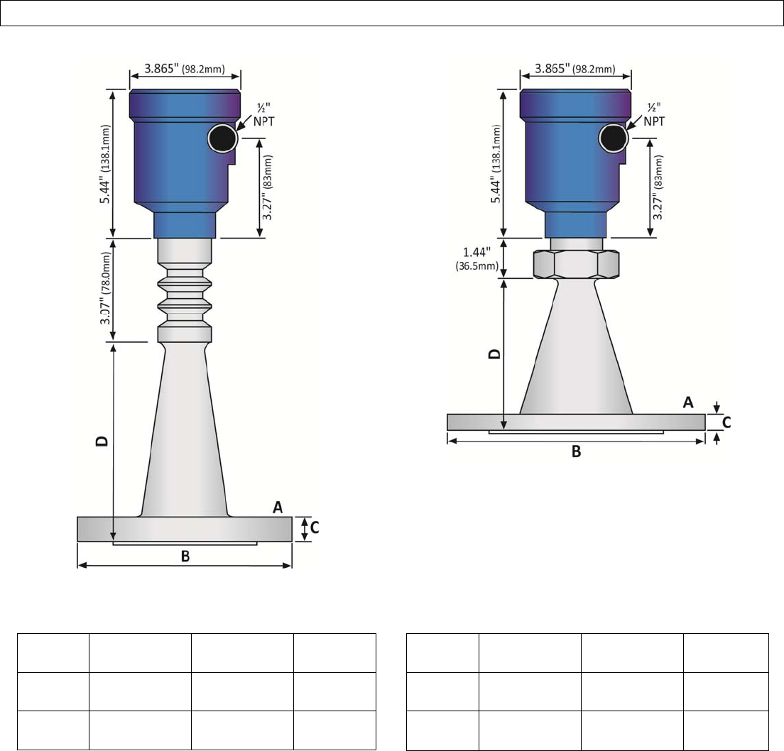
LR15Series(Threaded)
LR15Series(Flange) LR15Series(Threaded)AntennaDimensions
Diameter(X)Length(Y)
2”(48mm)5.51”(140mm)
3”(78mm)8.94”(227mm)
4”(98mm)11.34”(288mm)
LR15Series(Flange)Dimensions
Flange(A)Diameter(B)Thickness(C)
3”ANSI7.5”(190.5mm)0.88”(22.3mm)
4”ANSI9.0”(228.6mm)0.88”(22.3mm)
6”ANSI11.0”(279.4mm)0.94”(23.9mm)
LR15Series(Flange)AntennaDimensions
Diameter(D)Length(E)
2”(48mm)6.36”(161.5mm)
3”(78mm)9.78”(248.5mm)
4”(98mm)12.18(309.5mm)
UNRELEASED
Rev9_4MN301700Page9of72
INTRODUCTIONSectionOne
LR20Series
LR25Series
LR20SeriesFlange/AntennaDimensions LR25SeriesFlange/AntennaDimensions
Flange
(A)
Diameter
(B)
Thickness
(C)
Length
(D)
3”
ANSI
7.5”
(190.5mm)
0.88”
(22.3mm)
6.50”
(165mm)
4”
ANSI
9.0”
(228.6mm)
0.88”
(22.3mm)
8.00”
(203mm)
Flange
(A)
Diameter
(B)
Thickness
(C)
Length
(D)
4”
ANSI
9.0”
(228.6mm)
0.57”
(14.5mm)
5.71”
(145mm)
6”
ANSI
11.0”
(279.4mm)
0.63”
(16.1mm)
9.75”
(247.7mm)
UNRELEASED
Page10of72MN301700Rev9_4
INTRODUCTIONSectionOne
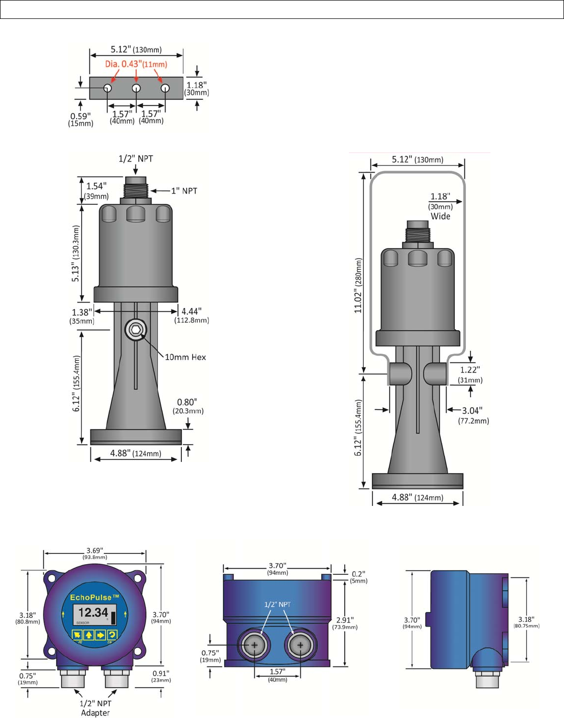
LR30SeriesBracket(TopView)
LR30Series(SideViewA)
LR30Series(SideViewB)
LR98SeriesDisplay
(FrontView)
LR98SeriesDisplay
(BottomView)
LR98SeriesDisplay
(SideView)
UNRELEASED

Rev9_4MN301700Page11of72
INTRODUCTIONSectionOne
SafetyPrecautions
AboutthisManual:PLEASEREADTHEENTIREMANUALPRIORTOINSTALLINGORUSINGTHISPRODUCT.This
manualincludesinformationontheEchoPulse™RadarLevelTransmitterfromFLOWLINE.Pleaserefertothepart
numberlocatedonthesensorlabeltoverifytheexactmodel,whichyouhavepurchased.
User’sResponsibilityforSafety:FLOWLINEmanufacturesabroadrangeoflevelsensingtechnologies.Whileeach
ofthesesensorsisdesignedtooperateinawidevarietyofapplications,itistheuser’sresponsibilitytoselectasensor
modelthatisappropriatefortheapplication,installitproperly,performtestsoftheinstalledsystem,andmaintainall
components.Thefailuretodosocouldresultinpropertydamageorseriousinjury.
ProperInstallationandHandling:Onlyprofessionalstaffshouldinstalland/orrepairthisproduct.Neverover
tightenthesensorwithinthefitting.Alwayscheckforleakspriortosystemstart‐up.
WiringandElectrical:Asupplyvoltageof16to26VDCisusedtopowertheEchoPulse™.Electricalwiringofthe
sensorshouldbeperformedinaccordancewithallapplicablenational,state,andlocalcodes.
MaterialCompatibility:TheenclosureismadeofeitherAluminumor316StainlessSteel(refertosensorpart
number).TheantennaismadeofStainlessSteel(SS),Polytetrafluoroethylene(PTFE)orNylon(PA66)withaVitonseal
(refertosensorpartnumber).Makesurethatthemodel,whichyouhaveselected,ischemicallycompatiblewiththe
applicationmedia.
Enclosure:Thesensorhousingisliquid‐resistant,butisnotdesignedtobeoperationalwhenimmersed(LR30series
isdesignedforsubmersionbutwillnotprovideatruelevelreadingwhilesubmersed).Mountthesensorinsuchaway
thattheenclosureandantennadonotcomeintocontactwiththeapplicationmediaundernormaloperational
conditions.Theenclosurehasacoverthatprovidesaccesstothepushbuttondisplaymoduleandterminalstripfor
wiring.Toopentheenclosure,youwillneedtotwistthecovercounter‐clockwise.Beforeclosingtheenclosure,make
surethattheenclosuregasketisproperlyseated,andthatanyconduitfittings,cableconnectorsorplugsareinstalled
correctlyandsealed.Note:IfusingtheFlowlineLM90‐1001(liquidtightfitting)onthe½”conduit,thecableminimumis
0.170”(4.3mm)andthemaximumis0.450”(11.4mm).
MakeaFail‐SafeSystem:Designafail‐safesystemthataccommodatesthepossibilityofsensorand/orpower
failure.FLOWLINErecommendstheuseofredundantback‐upsystemsandalarmsinadditiontotheprimarysystem.
Flammable,ExplosiveorHazardousApplications:EchoPulse™isapprovedforusewithingeneralpurpose
applicationsONLYandshouldNOTbeusedwithinclassifiedhazardousenvironments.
HandlingStatic‐SensitiveCircuitsandDevices:Whenhandlingtheinstrument(part),thetechnicianshouldfollow
thebelowguidelinestoreducethepossibilityofanelectrostaticchargebuild‐uponthetechnician’sbodyfrombeing
transferredtotheelectronicpart.Alwaystouchaknowngoodgroundsourcebeforehandlingapart.Thisshouldbe
repeatedwhilehandlingthepartandmorefrequentlyaftersittingdownfromastandingposition,slidingacrosstheseat
orwalkingadistance.Avoidtouchingelectricalterminalsofthepartunlessmakingconnections.DONOTopentheunit
coveruntilitistimetoworkonthepart.
UNRELEASED

Page12of72MN301700Rev9_4
GETTINGSTARTEDSectionTwo
SetupOverview
Thebelowhighlightstheinitialstepsinsettingupyoursensorforoperation.
1. PartNumber(SectionTwo)
1. Priortopurchasingthesensor,youshouldhavesubmittedaLevelApplicationQuestionnaire
(www.flowline.com/LAQ),whichbasedupontheinformationprovided,mayhaveresultedina
suggestedpartnumber.Whereso,confirmthatthesuggestedpartnumbermatchesthepartnumber
ofthepurchasedsensor.Ifanyoftheabovedoesnotmatchand/ormeetyourapplication
requirements,pleasecontactyourdistributor.
2. InstallSensor(SectionThree)
1. Informationonthelocationandmechanicalinstallationofthesensor.
3. WireSensor(SectionFour)
1. Informationontheelectricalwiringandpowerrequirementsofthesensor.
4. BasicConfiguration(SectionFive)
1. Beginbymeasuringthetankforallkeydimensions.
a. Accuracyinmeasurementwillresultinaccuracyofsensorperformance.
2. SettheUnitsofMeasurementforthesensor.
a. Unitscanbeconfiguredinbasicengineeringunitsoflength:Feet,Meters
3. SettheEmptyConfigurationforthesensorinthetank.
a. Thisisthe4mAsettingfortheoutput.
4. SettheFullConfigurationforthesensorinthetank.
a. Thisisthe20mAsettingfortheoutput.
5. SettheRange(MaximumRangeorMaxR)forthesensorinthetank.
a. Thesensorwillignoreanyechosignalreturnsbeyondthissetting.
6. SettheDeadBand(MinimumRangeorMinR)forthesensorinthetank.
a. Thesensorwillignoreanyechosignalreturnscloserthanthissetting.
7. ChecktheEchoCurve
a. Thisisaquickchecktodetermineifthesensorisreadingthecorrectlevel.
5. ProcessAdjustments(SectionSix)
1. InformationonOPTIONALadjustmentsforspecificprocessconditionsthatmayexistinyourapplication.
a. Fastfillingoremptyingofliquid.
b. Liquidsurfaceisturbulentoragitated.
c. Foamonthesurfaceoftheliquid.
d. Sensorinstalledinastillwellorsightglass.
UNRELEASED

Rev9_4MN301700Page13of72
GETTINGSTARTEDSectionTwo
6. AdvancedAdjustments(SectionSeven)
1. Reverse4‐20mAOutput
a. Reversesthecurrentoutfrom4mA@bottomand20mA@topoftankto20mA@bottomand
4mA@topofthetank.
2. Fail‐SafeSetting
a. Allowsforthepresettingofthecurrentoutputwhenasensorfailureoccurs.
3. MinimumCurrentSetting
a. Setstheminimumcurrentoutputforthesensor.
4. CreateaNewFalseEchoCurve
a. Amethodtomapoutfalseechosignalreturnswithinthetank.
5. UpdateanExistingFalseEchoCurve
a. Amethodtoupdatefalseechosignalreturnsforasectionofthetankthatwasnotexposed
duringthecreationoftheoriginalFalseEchoCurve.
7. Troubleshooting(SectionEight)
1. MeasurementStatus
a. Determinesthemeasurementreliabilityandgeneralstatusofthesensor.
2. PeakValues
a. Displaysthelowestandhighestlevelheightthatthesensorhasmeasuredindistance(d).
3. Simulation
a. Simulatesandhelpstodeterminetheaccuracyandlinearityofthesensor.
4. FirstEchoAdjustment
a. Increasesordecreasesthestrengthofthefirstechosignalreturn.
5. EchoCurveZoomIn
a. AmethodtozoominandviewtheEchoCurveoveraspecificrange.
6. FalseEchoCurveDelete
a. AmethodtodeleteapreviouslysavedFalseEchoCurvefrommemory.
7. Reset
a. Amethodtoresetthesensor’sconfigurationtotheoriginalfactorysetting.
UNRELEASED
Page14of72MN301700Rev9_4
GETTINGSTARTEDSectionTwo
PartNumber
Priortopurchasingthesensor,youshouldhavesubmittedaLevelApplicationQuestionnaire(www.flowline.com/LAQ),
whichbasedupontheinformationprovided,mayhaveresultedinasuggestedpartnumber.Whereso,confirmthatthe
suggestedpartnumbermatchesthepartnumberofthesensor.Thepartnumbercanbefoundontheoutsidelabelon
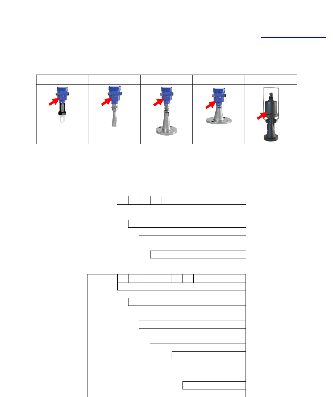
thesensorasshownbelow:
LR10Series
LR15Series
LR20Series
LR25Series
LR30Series
Thepartnumberwillindicatethesizeandtypeofmountingfittingrequiredforinstallingthesensor.Refertothebelow
partnumberdescriptionforspecificinformation.Ifanyoftheabovedoesnotmatchand/ormeetyourapplication
requirements,pleasecontactyourdistributor.
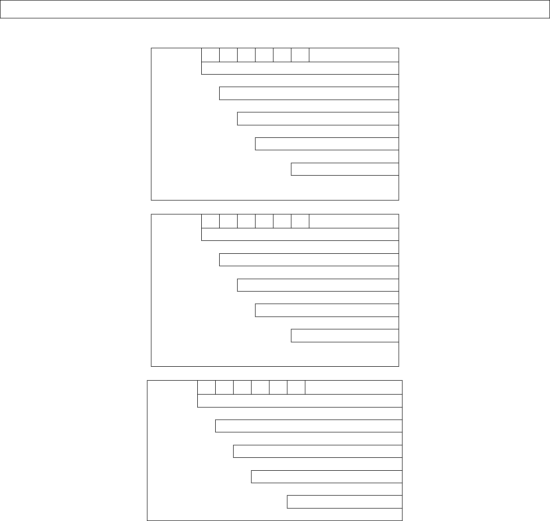
LR10‐0010
HousingMaterial
0‐Aluminum
ProcessConnection
0‐Thread1½"NPT
Output
1‐4‐20mA
Approval
0‐GeneralPurpose(cTUVus)
LR15‐0_10‐_0
HousingMaterial
0‐Aluminum
ProcessConnection
0‐Thread1½"NPT
3‐ANSIFlange
Output
1‐4‐20mA
Approval
0‐GeneralPurpose(cTUVus)
AntennaSize
2‐2"(48mm)Horn
3‐3"(78mm)Horn
4‐4"(98mm)Horn
FlangeSize
0‐ThreadedConn.
UNRELEASED
Rev9_4MN301700Page15of72
GETTINGSTARTEDSectionTwo
LR20‐031 0‐_0
HousingMaterial
0‐Aluminum
ProcessConnection
3‐ANSIFlange
Output
1‐4‐20mA
Approval
0‐GeneralPurpose(cTUVus)
FlangeSize
3‐3"Flange(ANSI)
4‐4"Flange(ANSI)
LR25‐031 0‐_0
HousingMaterial
0‐Aluminum
ProcessConnection
3‐ANSIFlange
Output
1‐4‐20mA
Approval
0‐GeneralPurpose(cTUVus)
FlangeSize
4‐4"Flange(ANSI)
6‐6"Flange(ANSI)
LR30‐0010‐10
HousingMaterial
0‐Nylon (PA66)
Mount
0‐Bracket
Output
1‐4‐20mA
Approval
0‐GeneralPurpose(cTUVus)
Display(LI98‐1001)
1‐WithDisplay
UNRELEASED

Page16of72MN301700Rev9_4
INSTALLSENSORSectionThree
InstallationRequirements
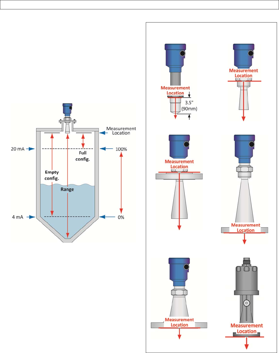
EchoPulse™measuresthedistancebetweenthesensorandtheliquidsurfacebelow.Typically,allmeasurementsfrom
thesensororiginatefromthebottomoftheantenna.RefertotheMeasurementReferenceCharttodeterminethe
locationwheremeasurementoriginatesonyoursensor.Toensurereliablemeasurement,adheretothefollowing
minimuminstallationrequirements:
1. Therearenoobstructionsbetweenthebottomedgeoftheinstalledantennaandthesurfaceoftheliquidbelow
includingladders,walls,tankseams,liquidinflows,rails,othersensors,mixerblades,heatingcoils,pumps,struts
orapparatus.Note:Additionally,whenthesensortransmitsamicrowavepulse,theRFsignalspreadsinaconical
shape(determinedbyitsbeamangle)overdistance.RefertotheBeamAngleCharttodetermine,whatifany,
additionalmeasurementspaceisrequiredtobefreeofsuchobstacles.Ifsuchitemsarepresent,thenaFalse
EchoCurveconfigurationmustbedone(SectionSeven).
2. Thesensormustbeinstalledwiththeantennaperpendiculartothesurfaceoftheliquid.
3. Thesensormustbeinstalledwithadistance≥19.7”(500mm)fromthesidewallofthetank.
4. Theliquidlevelmustnotbeallowedtoenterintothedeadband(blankingzone)ofthesensor.
5. Thesensorinstallationmustbedoneinaccordancewithrelevantlocalorfederalsafetyregulations.
6. Thesensormustbeconnectedtoelectricalground.
7. Donotusethehousingtoscrewthesensorintotheinstallationfitting(LR10&LR15Series).
1. Applyingatighteningforceagainstthehousingmaydamagethesensor.
8. Makesurethatallpartsofthesensorexposedtotheapplication,specificallyanyportioninstalledwithinthe
tank,aresuitablefortheprocess.
1. Consideranyeffectsfromtheapplicationtemperature,pressureormedia.
FCCConformity
ThisinstrumentcomplieswithPart15oftheFCCRules.Operationissubjecttothefollowingtwoconditions:(1)
thisinstrumentmaynotcauseharmfulinterference,and;(2)thisinstrumentmustacceptanyinterference
received,includinginterferencethatmaycauseundesiredoperation.
Changesormodificationsnotexpresslyapprovedbythemanufacturercouldvoidtheuser’sauthoritytooperate
theequipment.
Warning:Usermustkeepasafetydistanceofatleast20cmfromtheantenna.
NOTE:ThisequipmenthasbeentestedandfoundtocomplywiththelimitsforaClassAdigitaldevice,pursuant
topart15oftheFCCRules.Theselimitsaredesignedtoprovidereasonableprotectionagainstharmful
interferencewhentheequipmentisoperatedinacommercialenvironment.Thisequipmentgenerates,uses,
andcanradiateradiofrequencyenergyand,ifnotinstalledandusedinaccordancewiththeinstructionmanual,
maycauseharmfulinterferencetoradiocommunications.Operationofthisequipmentinaresidentialareais
likelytocauseharmfulinterferenceinwhichcasetheuserwillberequiredtocorrecttheinterferenceathisown
expense.
Thisequipmentisnotallowedtobeconnectedtopublicutilitypowerlines.
UNRELEASED
Rev9_4MN301700Page17of72
INSTALLSENSORSectionThree
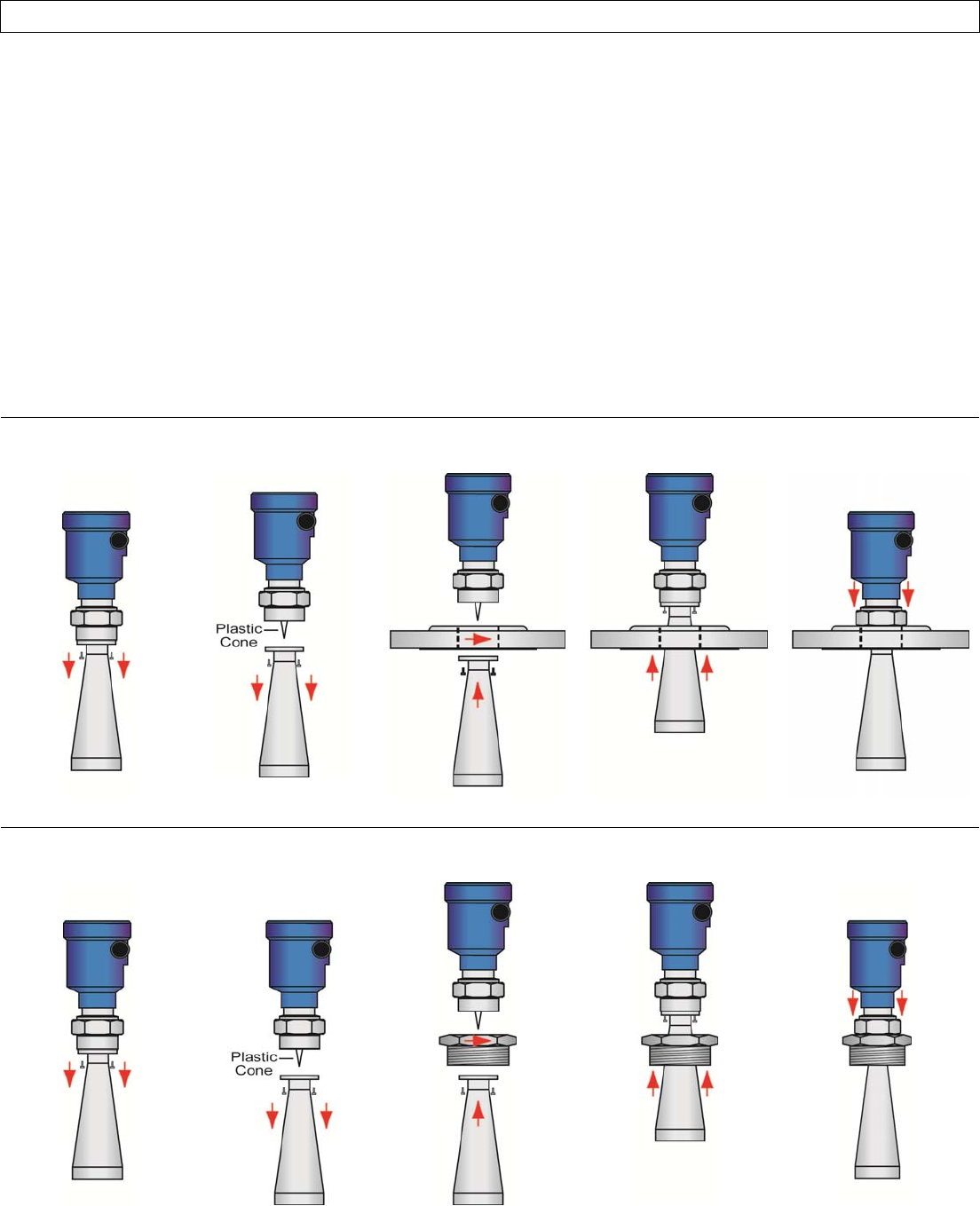
LR15AntennaPreparation
TheLR15Seriesantenna(only)mayberemovedfromthesensortoallowaflangeorreducerbushingaccessorytobe
attachedtothe1½”NPTmountingthreadsand/or,theantennamaybeinsertedfromwithintheinsideofthetank
throughthebottomofanexistingfitting(wherethebaseoftheantennaistoowidetopassthroughthefittingfromthe
top).Referencingtheillustrations,followthebelowstepstodisconnect,mountandreattachtheantenna.
1) Loosenandremovethefour(4)socketscrewsusinga3mmAllenwrench.
2) Carefullyremovetheantenna.Note:Donotremoveordamagetheplasticconewithintheantennasocket.
3) Inserttheantennathroughthebottomofthefitting.Note:Ifdoingsofromtheinsideofthetank,makesureto
secureit,soastopreventtheantennafromfallingintothetank.
4) Connectthesensortotheantennasocketandreattachthefour(4)screwsusinga3mmAllenwrench.
5) Attachthesensortothefittingasnecessary.
AddaFlange
RemoveScrewsRemoveAntennaInsertAntennaConnectAntennato
Sensor,AttachScrews
ThreadSensorto
Flange
AddaReducerBushing
RemoveScrewsRemoveAntennaInsertAntennaConnectAntennato
Sensor,AttachScrews
ThreadSensorto
ReducerBushing
UNRELEASED
Page18of72MN301700Rev9_4
INSTALLSENSORSectionThree
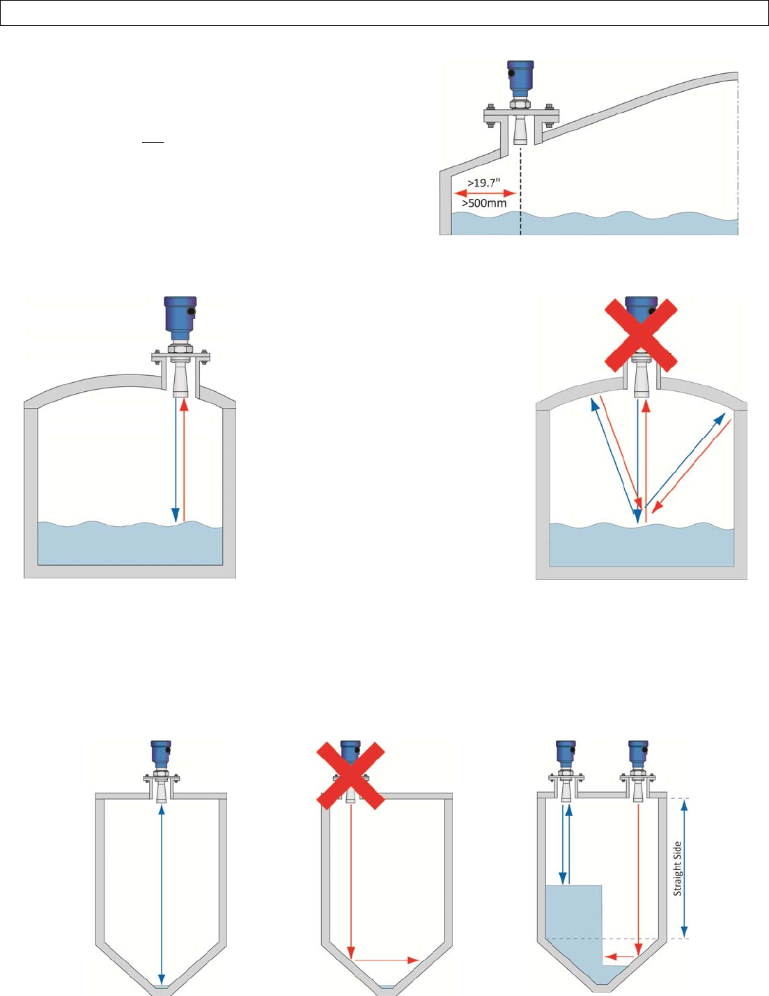
MountingPosition
Theminimumdistance(independentofbeamangle)thatthe
sensorcanbemountednexttothestraightsidewallofthetank
is19.7”(500mm)asmeasuredfromthesensorcenterlinetothe
sidewall.Ifyouarenotabletoinstallthesensormorethan
19.7”(500mm)awayfromthesidewall,orifthereismaterial
builduponthesidewall(withinthebeamangle),performa
FalseEchoCurveduringinitialconfiguration.
Avoidmountingthesensorinthecenterofadometoptank.Thecenterofsuchatankwillmultiplytheechoes,making
sensoroperationdifficult.
CorrectMounting
Sensormountedoffcenterinadome
toptank.
IncorrectMounting
Sensormountedinthecenterofa
domedtoptankresultinginmultiple
echoes.
Inconebottomtanks,itcanbeadvantageoustomountthesensorinthecenterofthetank,makingitpossibleforthe
sensortomeasureclosertothebottomofthetank.Ifthesensorismountedoveranangledbottom,andthelevel
dropsbelowtheangle,theechowillbedeflectedawayfromthesensor,resultinginpooroperation.Thesensorcanbe
mountedoveranangledbottomaslongasthelevelismaintainedwithinthestraightsidewallsothesensorwillreceive
echoreturns.
CenterMount‐CorrectLevelBelowSideWall‐IncorrectLevelAboveSideWall–Correct
UNRELEASED
Rev9_4MN301700Page19of72
INSTALLSENSORSectionThree
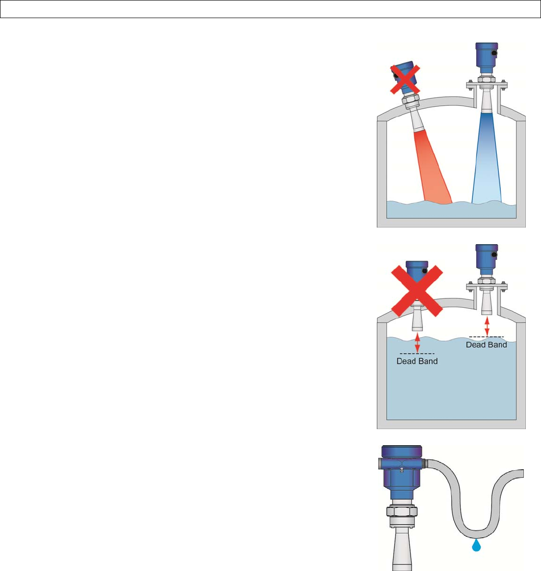
MounttheSensorPerpendiculartotheLiquidLevel
Alwaysmountthesensorperpendiculartothesurfaceoftheliquid.Thiswill
enablethereturnechoestoreachthesensor.Mountingthesensoroff‐axiswill
resultinweakerreturnechoesornoreturnechoes,dependingonthedegree
ofangle.
ConsidertheDeadBand
Thesensorhasadeadband(blankingdistance)of12”(30.48mm)asitsdefault.
Thedeadbandcanbeloweredtowithin2”ofthebottomoftheantenna
(consultwithfactory).Thisisanupclosedistancewherethesensorisnot
abletomeasurethelevelwithinthisrange.Typically,themeasurement
locationforthesensorisatthebottomoftheantenna.Whenidentifyinga
locationforsensorinstallation,takeintoaccountthelengthoftheantenna
combinedwiththedeadbandofthesensor.
AvoidCondensationintheConduit
Youcangiveyourinstrumentadditionalprotectionagainstmoisture
penetrationbyleadingtheconduitconnectionorcabledownwardinfrontof
thecableentry.Condensationintheconduitwillthusnotenterthesensor
enclosure.
UNRELEASED
Page20of72MN301700Rev9_4
INSTALLSENSORSectionThree
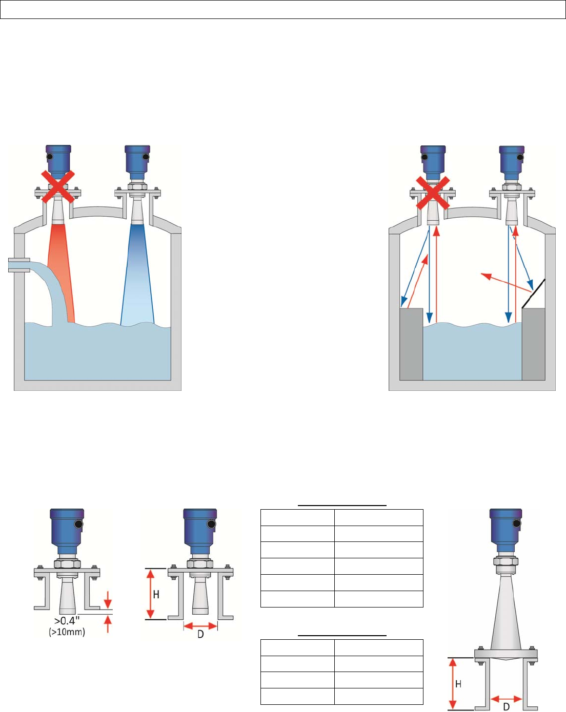
AvoidObstructionsintheBeamPath
Donotmountthesensorinorabovethefillstream,otherequipment(ladders,pumps,mixers)orstructureswithinthe
beampathofthesensor.Suchitemscancreatefalseechoreturnsandpreventtheactuallevelfrombeingseenbythe
sensor.Findalocationwherethesensorhasaclearviewoftheliquidsurface.Ifyourtankhasotherequipmentnearor
withinthebeampathofthesensor,aFalseEchoCurveshouldbeperformedduringinitialconfiguration.
FillStreamMounting
Mountingonleftincorrectlypositions
sensorabovethetankfillstreaminlet.
Mountingonrightiscorrectasthe
sensorhasanunobstructedviewto
theliquidlevelbelow.
ReflectorInstallation
Mountingonleftincorrectlyallows
thesensortoreceivefalseecho
returnsfromthestep.
Mountingonrighthasanangled
baffle‐boardmountedoverthestep,
whichpreventsthefalseechofrom
returningtothesensor.Assuch,the
sensoronlyreceivescorrectecho
returnsfromtheliquidlevel.
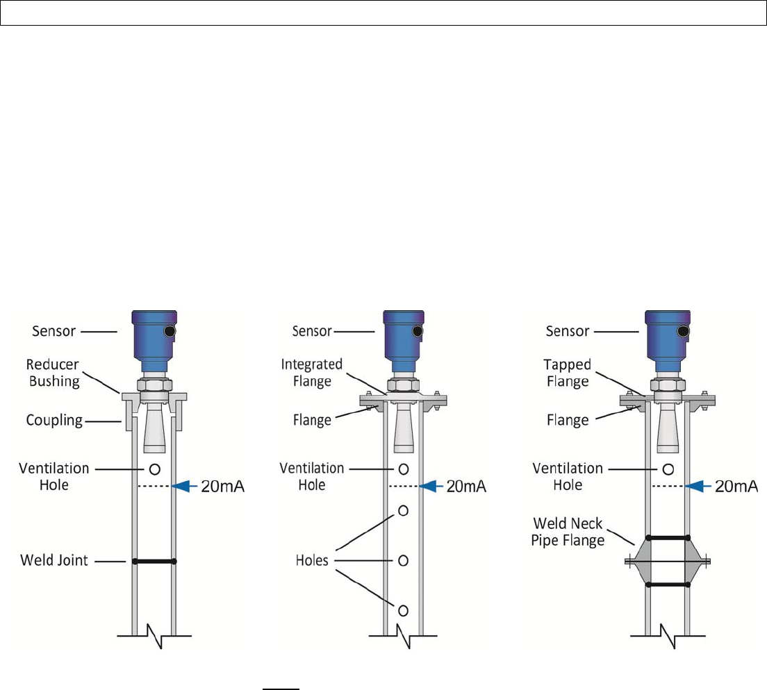
FlangeRiserInstallation
Wheninstallingthesensoronaflangewithariser(oranyfittingthatistallandnarrow),theantennamustprotrudeat
least0.4”(10mm)fromthebottomoftheriser.Thesensorcanbeinstalledwithintheriseraslongastheliquidhasa
strongreflectiveproperty(dielectricconstant)providingastrongechoreturn.Thebelowinformationdescribesthe
maximumdistancethattheantennacanberecessedwithinariserbasedonthediameterandheightofthefitting.
AntennaExtension
LR15Series
LR10&LR15Series
Diameter(D)Height(H)
1‐½”7.9”(200mm)
2”(50mm)9.8”(250mm)
3”(80mm)11.8”(300mm)
4”(100mm)19.7”(500mm)
6”(150mm)31.5”(800mm)
LR20&LR25Series
Diameter(D)Height(H)
3”(80mm)11.8”(300mm)
4”(100mm)19.7”(500mm)
6”(150mm)31.5”(800mm)
LR20Series
UNRELEASED
Rev9_4MN301700Page21of72
INSTALLSENSORSectionThree
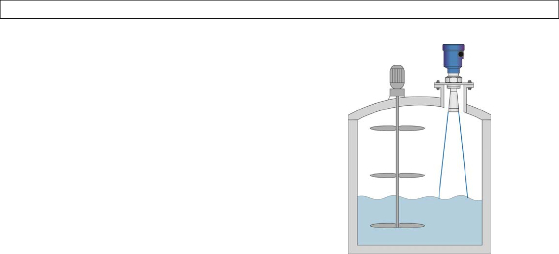
AgitatororMixer
Ifthereareagitatorsormixersinthetank,thesensor
shouldbemountedasfarawayfromthebladesas
possible.Oncetheinstallationiscomplete,aFalseEcho
Curveshouldbepreformedwhiletheagitatorormixeris
inmotiontomapoutandeliminatefalseechoreturns
fromtheblades.Ifsignificantfoamand/oragitationexists
withintheapplication,astand‐pipeinstallationshouldbe
considered.
UNRELEASED
Page22of72MN301700Rev9_4
INSTALLSENSORSectionThree
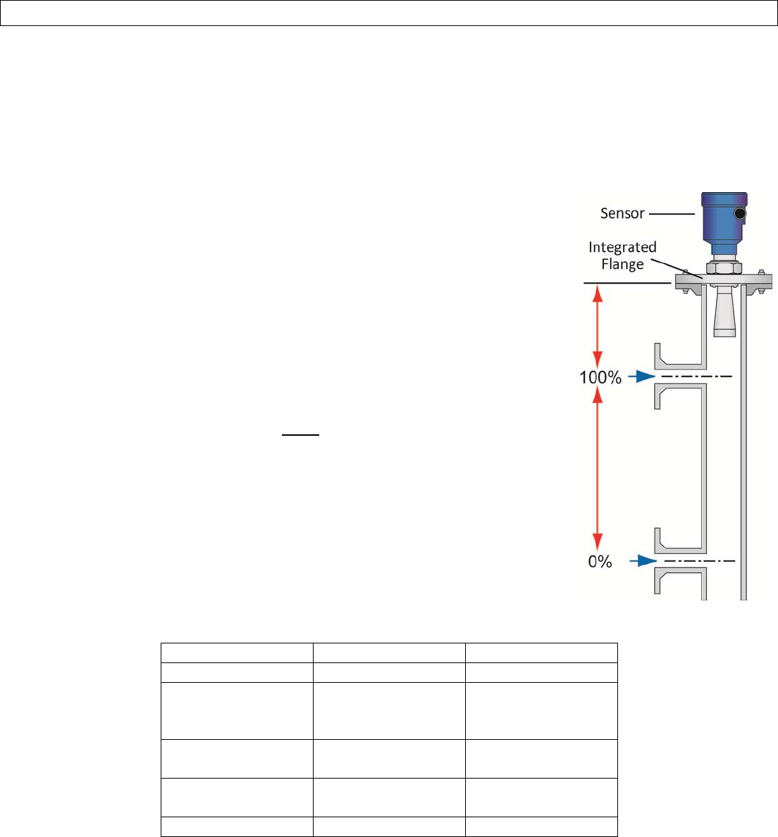
StandPipeInstallation
Toavoidissuesfromturbulence,substantialfoamorotherequipmentinthesensorsbeampath,installthesensor
withinastandpipe(stillwell).Astandpipeinstallationcanbeusedwithliquidswithadielectricconstantaslowas1.9.
Note:Theuseofastandpipeisnotrecommendedwithliquidsthatsignificantlycoatorscale.Asarule,iftheinsidewall
ofthetankhasmaterialbuild‐up,thentheinsideofthestandpipewillalsohavebuild‐upthatwillaffectthesensor’s
operation.Wheninstallingasensorinastandpipe,followthebelowguidelines:
1. TheFullConfigurationsetting(20mA)mustbebelowtheupperventholeandthebottomoftheantenna.
2. TheEmptyConfigurationsetting(4mA)istypicallyplacedatornearthebottomofthestandpipe.
3. TheStandPipefunctionmustbeactivated.ItcanbefoundunderMediumintheConfigurationMenu.The
innerdiameterofthestandpipemustbeenteredwithinthisfunction.
4. ItisrecommendedtoperformaFalseEchoCurvewhenthesensorisinstalledinastandpipe.
StandPipeConstruction
1. Thestandpipematerialmustbemetalwithasmoothinnerpipewall.Theminimumpipesizeisdependentupon
theSeriesandantennalength.TheLR10andLR15sensorcanbeappliedinpipesizes≤3”(76.2mm).
2. Anyweldedjointmustbestraightwithagapsize≤1/254”(0.1mm).
3. Flangesshouldbeweldedtothestandpipetube.
4. Inthecaseofapipeextensionwithaweldedneckflangeorpipecollar,makesuretheinnersurfacesarealigned
andaccuratelyjoinedtogether.
5. Whensecuringthepipetothetank,donotweldthroughthepipewall.
1. Roughnessontheinsidecausedbyunintentionalpipepenetrationshouldberemoved.
2. Notdoingsowillcausestrongfalseechoreturnsandencouragebuildupwithinthepipe.
6. Thediameterofanyholesalongthepipemustbe≤1/5”(5mm).
1. ThetopventilationholemustbeabovetheFullConfigurationsetting(20mA).
2. Theholesmustbeverticallyalignedononesideofthepipewithallburrsremoved.
3. Thenumberofholesdoesnotmatter.
7. Theinnerdiameterofthepipecannotchangeovertheentirepipelength.
UNRELEASED
Rev9_4MN301700Page23of72
INSTALLSENSORStepThree
SightGlassInstallation
Analternativetoastandpipeisinstallingthesensorwithinasightglassmountedoutsideofthetank.Sightglass
installationscanavoidissuesfromturbulence,substantialfoamorotherequipmentinthesensorsbeampath.Note:
Theuseofasightglassisnotrecommendedwithliquidsthatsignificantlycoatorscale.Asarule,iftheinsidewallofthe
tankhasmaterialbuild‐up,thentheinsideofthesightglasswillalsohavebuild‐upthatwillaffectthesensor’soperation.
Wheninstallingasensorinasightglass,followthebelowguidelines:
1. TheFullConfigurationsetting(20mA)mustbeplacedatorbelowtheupper
tankconnectionpipe.
2. TheEmptyConfigurationsetting(4mA)mustbeplacedatorabovethebottom
tankconnectionpipe.
3. TheStandPipefeaturemustbeactivated.ItcanbefoundunderMediuminthe
ConfigurationMenu.Theinnerdiameterofthesightglassmustbeentered
withinthisfunction.
4. ItisrecommendedtoperformaFalseEchoCurvewhenthesensorisinstalled
inasightglass.
SightGlassConstruction
1. Thesightglassmaterialmustbemetalwithasmoothinnerpipewall.The
minimumpipesizeisdependentupontheSeriesandantennalength.TheLR10
andLR15sensorcanbeappliedinpipesizes≤3”(76.2mm).
2. Thereisaminimumdistance>11.8”(>300mm)betweenthebottomofthe
antennaandthetopedgeoftheuppertankconnectionpipe.
3. Anyweldedjointsmustbestraightwithagapsize≤1/254”(0.1mm).
4. Flangesshouldbeweldedtothesightglasstube.
5. Theinnerdiameterofthesightglasscannotchangeovertheentirepipelength.
StandPipe/SightGlassPipeSizevs.Series
SeriesMinimumPipeMaximumPipe
LR10:All2”3”
LR15:2”Antenna
3”Antenna
4”Antenna
2”
3”
4”
8”
LR20:3”Antenna
4”Antenna
3”
4”8”
LR25:4”Antenna
6”Antenna
4”
6”8”
LR30:AllN/AN/A
UNRELEASED
Page24of72MN301700Rev9_4
INSTALLSENSORSectionThree
LR30SensorInstallation
TheLR30isuniquewithintheEchoPulse™sensorfamily.Itisdesignedforuseinwaterprocessing,liftstations,storm
waterandsumpprocessconditions,whichrequirethesensortobeinstalledinlocationsthatareoftenbelowgrade
wherefloodingisapossibility.Thedesignofthesensorallowsfortheunittobesubmersed.Whilethesensorwillnot
bedamagedwhilesubmersed,thesensorwillnotprovidecorrectlevelreadingswhensubmersed.Note:Donot
attempttoopenthesensorhousing.Doingsowilldamagetheseal,allowmoistureintothesensor,andcauseasensor
failure.Thesensoralsofeaturesasubmersionresistant10mcableandIP67remotepushbuttondisplaymodule(LR98
describedonthefollowingpage)throughwhichthesensorcanbeconfiguredandthelevelwillbedisplayed.
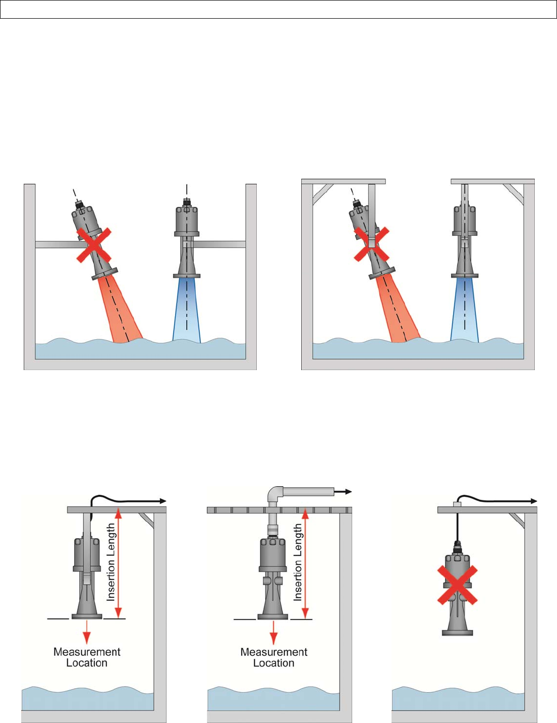
MounttheSensorPerpendiculartotheLiquidLevel
BracketorConduitMount
Mountingfromthebracketorfromthe1”conduitconnectorarebothacceptablemountingmethods.The
measurementlocationforallreadingsislocatedatthebottomofthesensor.Remembertotakeintoaccountthe
installedinsertionlengthofthesensorwhencalculatinglevelheightwithinthesump.Note:Nevermountthesensor
hangingfromthecable.Thistypeofinstallationwillnotsecurethesensor,maydamagethecableconnectionandwill
resultininconsistentlevelreadingsasthesensorsways.
UNRELEASED
Rev9_4MN301700Page25of72
INSTALLSENSORSectionThree
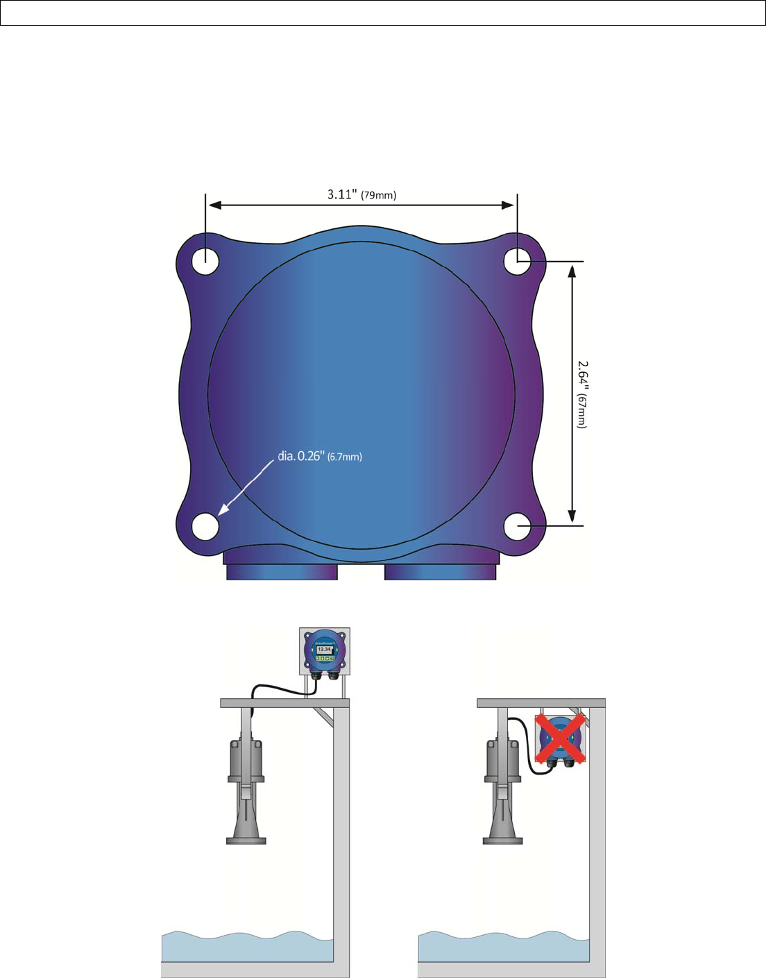
LR98DisplayInstallation
TheLR98isawallmountIP67remotepushbuttondisplaymodulethat’susedtoconfigureanddisplaylevelreadings
fromtheLR30sensor.TheLR98shouldbemountedinalocationwherethedisplaycanbeeasilyread.Note:TheLR30
cablelengthis32.8’(10m)whichisalsothemaximumsignaldistancebetweentheLR30andLR98.Takethatinto
accountwhenselectingtheLR98mountinglocationandusethebelowdrill‐holetemplateforinstallingthedisplay.
LR98RearView
Note:MakesurethattheLR98displayismountedinanabovegradelocationwhereitwillnotbecomesubmersed.
UNRELEASED
Page26of72MN301700Rev9_4
WIRESENSORSectionFour
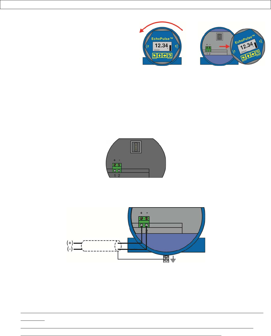
RemovetheDisplay
Toaccesstheterminalstripandconduitports,youfirst
needtoremovethedisplay.Gentlytwistthedisplay
counter‐clockwiseuntilyoufeelthedisplayunlockfrom
thehousing.Next,liftthedisplayfromthehousingto
viewtheterminalstripandwireaccessports.Note:This
procedureappliestoallsensorsincludingtheLR30with
itsLR98remotedisplay.
SupplyVoltage
Thesensorpowersupplyandcurrentsignalsharethesametwo‐wireshieldedcable.Thesensorsupplyvoltageshould
neverexceed26VDC.Alwaysprovidecompleteelectricalandphysicalseparationbetweenthesensorsupplycircuitand
themaincircuit.Note:Rememberthattheoutputvoltageofthepowersupplycanbelowerundernominalload(witha
sensorcurrentof20.5mAor22mA)and/orwiththeadditionofotherinstrumentsplacedwithinthecircuit.Ifvoltage
spikesorsurgesareexpected,adequateisolationprotectionmustalsobeprovided.
TerminalWiring
Thepositive(+)andNegative(‐)terminalsareforconnectiontoa24VDCpowersupplyortoa4‐20mAlooppowersource.
Thewiretotheterminalscanbeextendedupto1,000feetusing22gaugeorlargerwire.
Thesensorshouldbewiredwithshielded2‐conductorcable(16to22AWG)toprotectfromelectromagnetic
interference.Ifusingaliquidtightconnector,selectacablewithanouterdiameterthatisdesignedtoensurean
effectivesealwiththeconnector[typicallybetween0.20”to0.35”(5to9mm)].
Electrical,UsageandSafety
1. Wiringshouldalwaysbedonebyalicensedelectricianinaccordancewithnational,stateandlocalcodes.
2. Neveruseageneralpurpose(cTUVus)sensor(LR10,LR15,LR20,LR25,LR30Series)inenvironmentsclassifiedas
hazardous.
3. Wherepersonalsafetyorsignificantpropertydamagecanoccurduetoaspill,theinstallationmusthavea
redundantfail‐safebackupsysteminstalledwhichaccountsforsensorand/orpowerfailure.
UNRELEASED
Rev9_4MN301700Page27of72
WIRESENSORSectionFour
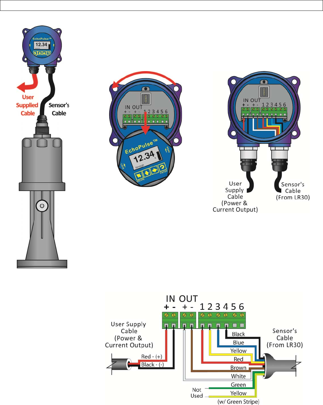
LR30SensortoLR98Display
Note:TheIN[Positive(+)and
Negative(‐)]terminalsarefor
connectiontoa24VDCpower
supplyor4‐20mAlooppower
source.The4‐20mAwiresto
theLR98terminalscanbe
extendedupto1,000feet
using22‐gaugeorlarger
wires.Theseterminalsare
equivalenttothe(+)and(‐)
terminalsdescribedonthe
previouspage.
TheLR98displayisusedwiththeLR30sensor.Theattached8‐conductorsensorcable
willwiredirectlyintothedisplayterminals.Ashieldedtwo‐wirecable(usersupplied)is
requiredtoprovidepowertoandthecurrentoutputsignalfromthedisplay.
LR98DisplayRemovalLR98DisplayTerminals
1. Removethedisplay(asdescribedonthepreviouspage)toaccesstheinputand
outputterminalswithintheLR98display.
2. Referencingthebelowdiagram,connecttheappropriatelycolored6‐conductors
(of8total)fromtheLR30sensorcabletoOut[(+)&(‐)]&terminals1‐4onthe
LR98display.
3. Theremaining2‐conductors(GreenandYelloww/Stripe)willnotbeused.
4. Finally,connectthe2‐conductors(fromtheusersuppliedCable)forlooppower
inputandcurrentoutputtothe(+)and(‐)terminalsontheLR98display.
UNRELEASED
Page28of72MN301700Rev9_4
WIRESENSORSectionFour
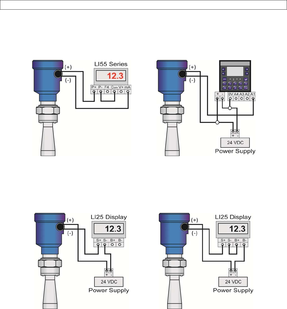
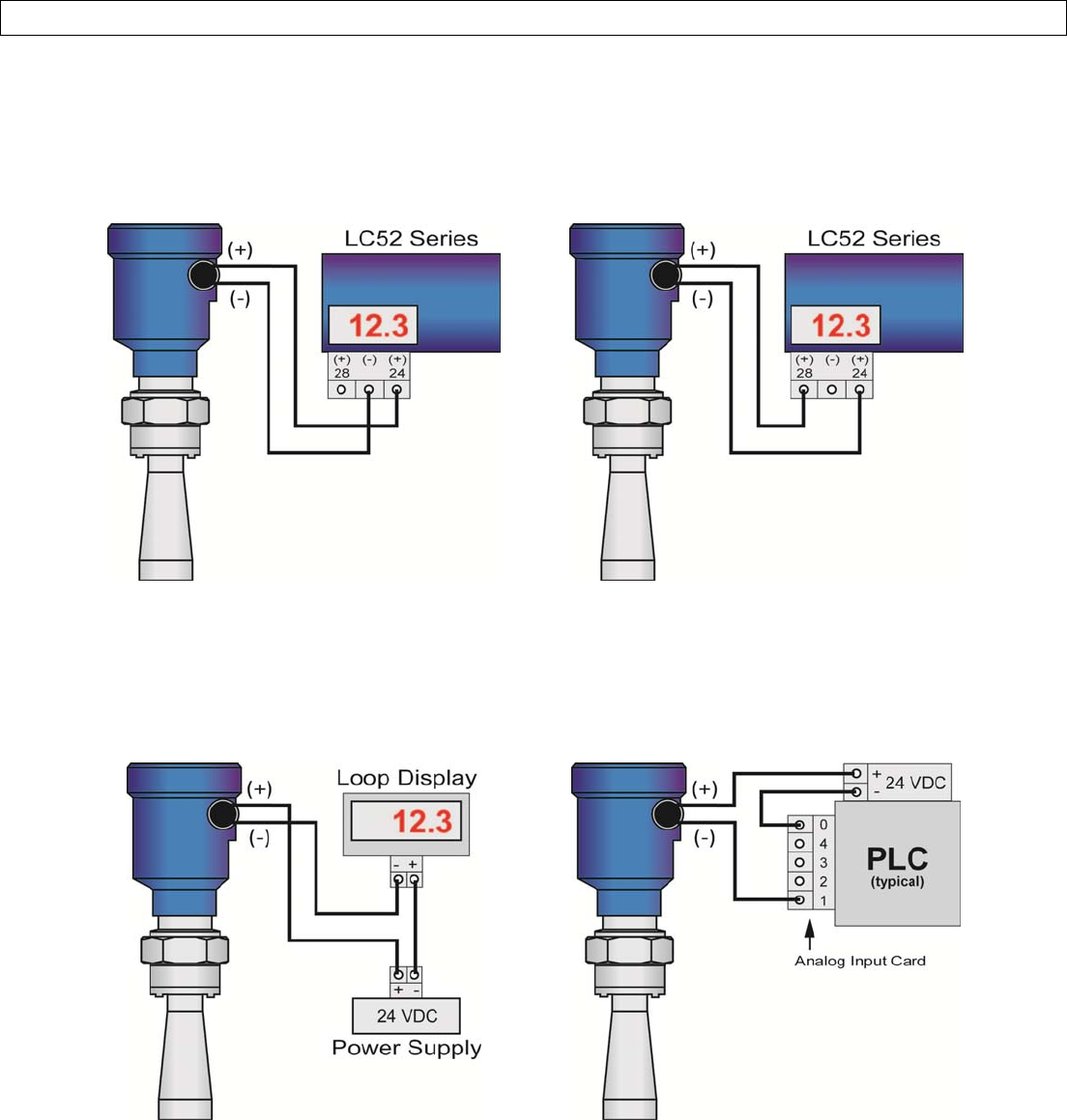
WiringtoDisplays,Controllers&PLC’s
BelowareexamplesofhowtowireEchoPulse™tocommondisplays,controllersandPLC’s.
DataView™LI55Series
LevelController
Commander™LI90Series
Multi‐TankLevelController
DataLoop™LI25Series
LevelIndicator
(WithoutBacklight)
DataLoop™LI25Series
LevelIndicator
(WithBacklight)
UNRELEASED
Rev9_4MN301700Page29of72
WIRESENSORSectionFour
WiringtoDisplays,Controllers&PLC’s
DataPoint™LC52Series
LevelController
(*JWAMode‐FactorySetting)
DataPoint™LC52Series
LevelController
(*JWBMode)
GenericLoop
PoweredDisplay
GenericPLC
*RefertotheDataPoint™LC52SeriesLevelControllermanualforinformationonJWAmodeandJWBmodesettingsin
thecontroller.
UNRELEASED
Page30of72MN301700Rev9_4
CONFIGURATIONSectionFive
BasicConfigurationOverview
Belowarethe7basicstepstoconfigurethesensorforoperation.Eachstepisdescribedindetailonthefollowingpages
1. MeasuretheTank
1. Beginbymeasuringthekeytankandfittingdimensions.Correcttankdimensionswillresultinaccurate
sensormeasurement.
2. SettheUnitsofMeasurement
1. UnitscanbeconfiguredinbasicengineeringunitsoflengthincludingFeetorMeters.
3. SettheEmptyConfiguration
1. Thisistheemptysetting(4mA)forthetank.
4. SettheFullConfiguration
1. Thisisthefullsetting(20mA)forthetank.
5. SettheRange(MaximumRangeorMaxR)
1. Thisisthemaximummeasurementrangeforthesensor.Thesensorwillignoreallechoreturnsbeyond
thissetting.
6. SettheDeadBand(MinimumRangeorMinR)
1. Thisistheminimummeasurementrangeforthesensor.Thesensorwillignoreallechoreturnscloser
thanthissetting.
7. ChecktheEchoCurve
1. Thisisaquickdiagnostictooltodetermineifthesensorisreadingthecorrectlevel.
UNRELEASED
Rev9_4MN301700Page31of72
CONFIGURATIONSectionFive
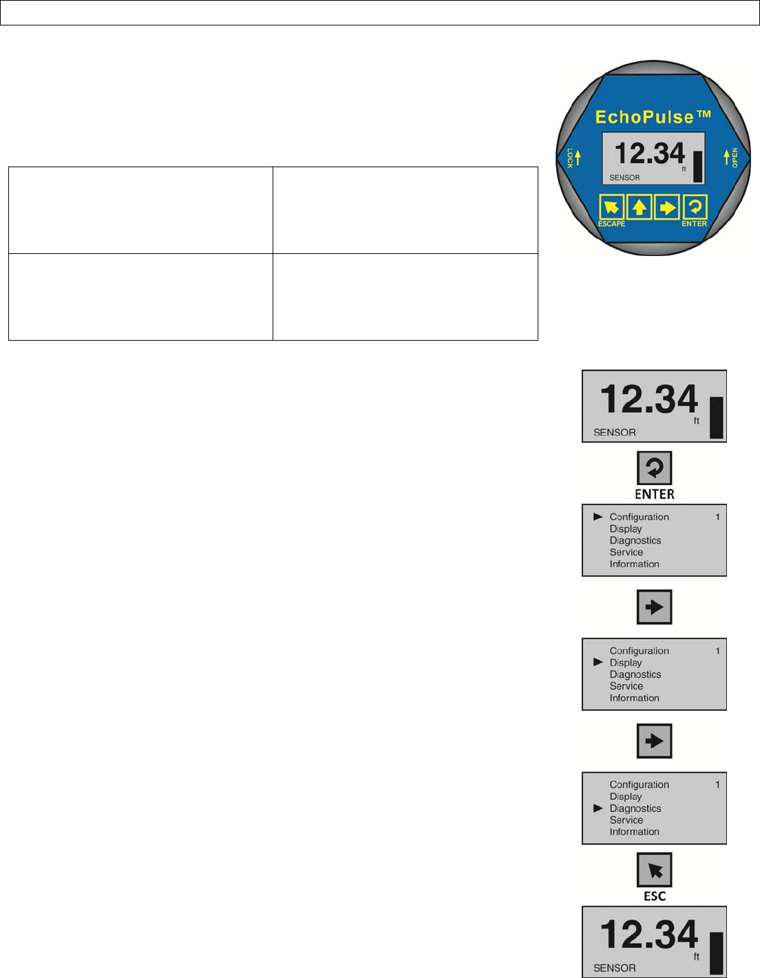
UsingtheDisplay
ThedisplaymodulefeaturesadotmatrixLCDdisplaywith4pushbuttonsona
removablepuck.Outofthebox,thedisplayindicateslevelinfeetanddepictsthe
levelwithinthe4‐20mAspanonabargraphattherightsideofthedisplay.Thefour
buttonsperformthefollowingfunctions:
ESCAPE
o Exitconfigurationmode
o Returntoahighermenulevel
o DisplayEchoCurve
UpArrow
o Modifyparametervalues
o Choosedisplaymode
RightArrow
o Chooseconfigurationoptions
o Chooseparameterdigitstoedit
o Displaycontentsofparameters
ENTER
o EnterMenuandOptions
o Confirmconfigurationoptions
o Confirmchangestoparameters
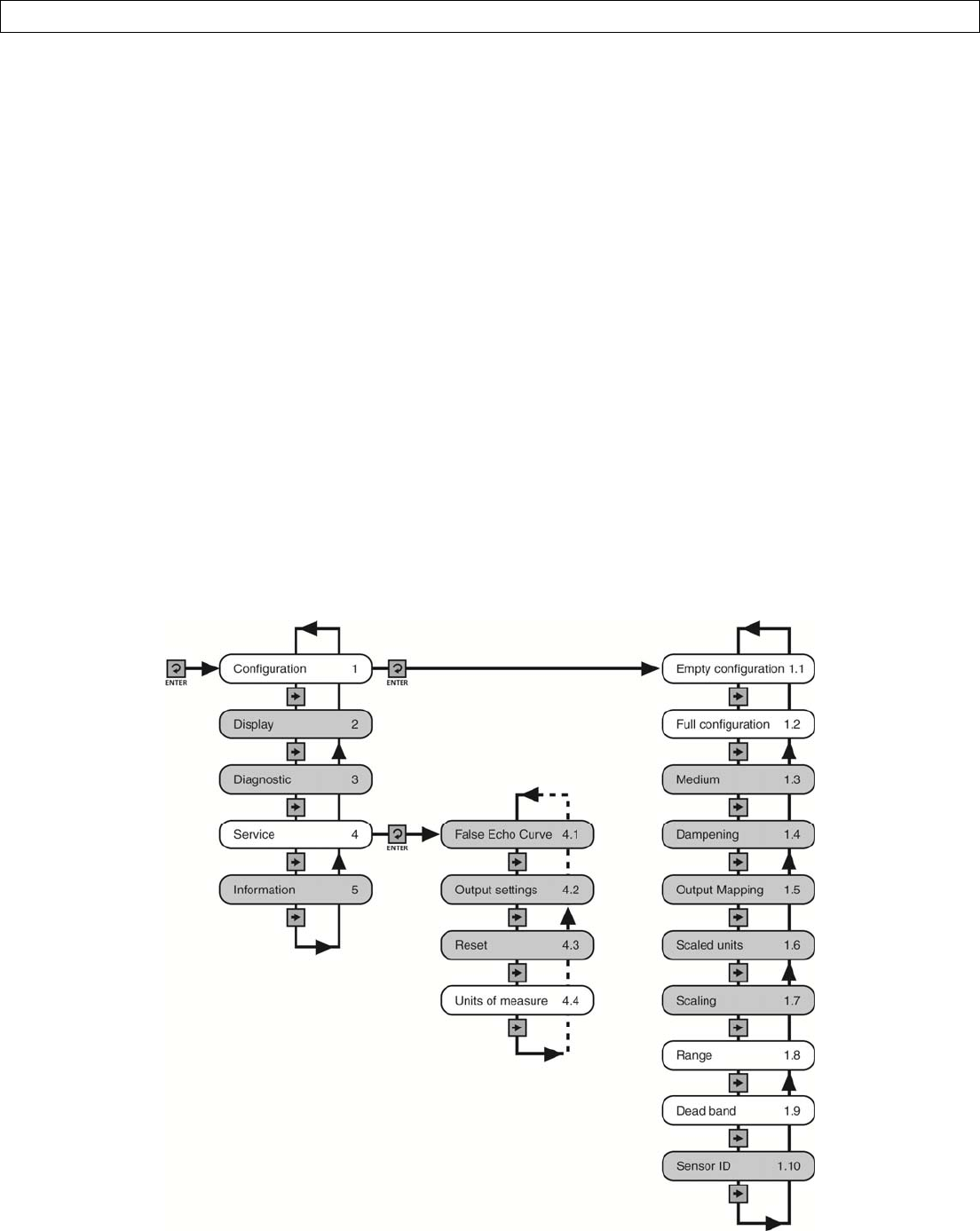
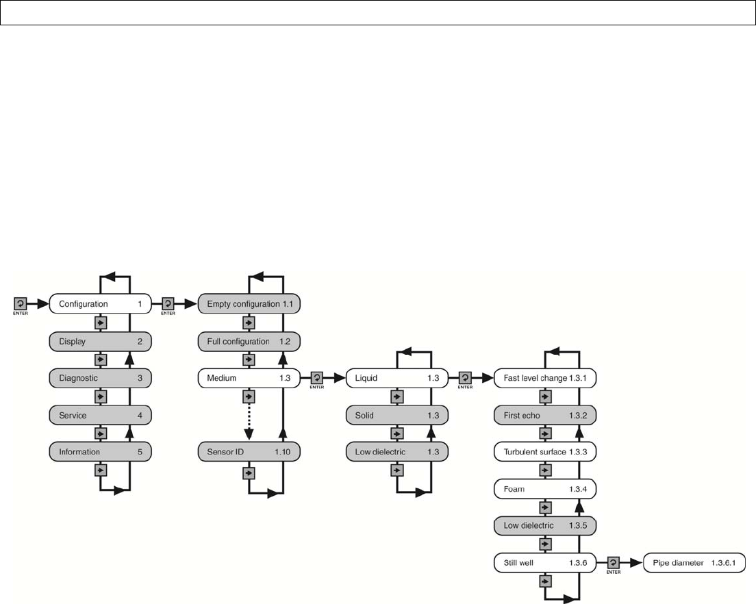
MenuIntroduction
1. ToentertheMainMenu(fromtheMainScreen),presstheENTERbutton.
2. UsetheRightArrowbuttontoscrollthroughtheMainMenuoptions.
1. Configuration‐Belowaretheconfigurationmenufunctions:
a. EmptyConfiguration
b. FullConfiguration
c. Medium
d. Dampening
e. OutputMapping
f. ScaledUnits
g. Scaling
h. Range
i. DeadBand
j. SensorID
2. Display‐Thismenufunctionsetsthedisplaymodeandcontrast.
3. Diagnostics‐Belowarethediagnosticmenufunctions:
a. MeasurementofPeakValues
b. MeasurementStatus
c. EchoCurve
d. Simulation
4. Service‐Withintheservicemenufunctions,youcanstoreaFalse
EchoCurve,setunitsofmeasurement,changeoutputsettings,reset
configurationsettings,setlanguageorsetaPINforthesensor.
5. Info‐Thisitemprovidesinformationonthesensor’stype,serial
number,dateofmanufactureandsoftwareversion.
3. Toselectoneofthefunctions,pressENTER.
4. Toexittheprogrammingmode,pressESC.
UNRELEASED
Page32of72MN301700Rev9_4
CONFIGURATIONSectionFive
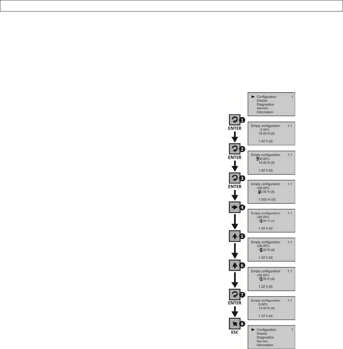
ChangingDisplayValues
ThenumericvaluesaresetusingtheRightArrowandUpArrowbuttons.PresstheRightArrowbuttontoselectthe
nextdigitandtheUpArrowbuttontoincrementthedigitvalue.Thedigitbeingchangedishighlighted.PresstheEnter
buttontoacceptasettingortheEscbuttontoexitwithoutsavingchanges.Thebelowexerciseillustrateshowto
changethevalueofanEmptyconfiguration.Followthestepstochangethesettingfrom10.00ftto12.00ft.This
exampleappliestoallfunctionalsettingsstartingfromtheMainMenu.
1. FromtheMainMenu,pressENTERtoadvanceinto
theConfigurationmenu.
1. Emptyconfigurationwillappearonthetop
lineofthescreen.
2. FromEmptyconfiguration,pressENTER.
1. The“+”signwillbehighlightedonthescreen.
2. Thisistheadjustmentforthepercentage
setting.
3. PressENTERtomovedowntothedistancesetting.
1. Thefirstdigit,“1”,willbehighlighted.
4. PressRightArrowtomoveonedigittotheright.
1. UsetheRightArrowbuttontomovethedigit
onespacetotheright.
2. PressingRightArrowonthelastdigitwill
jumpbacktothefirstdigit.
5. PressUPARROWtoincreasethedigitfrom“0”to
“1”.
6. PressUPARROWtoincreasethedigitfrom“1”to
“2”.
1. UsetheUPARROWbuttontoincreasethe
digitbyoneunit.
2. After“9”,thedisplaywilljumpbackto“0”.
7. PressENTERtoacceptthesettingas12.00.
8. PressESCAPEtomovebacktotheMainMenu.
UNRELEASED
Rev9_4MN301700Page33of72
CONFIGURATIONSectionFive
Step1‐MeasuretheTank
Measuringthetankisoneofthemostimportantaspectsin
configuringthesensor.Whenmeasuringthetank,takeinto
accountthelocationofthesensorwithrespecttofittings,
risers,dometopsandbottoms,andidentifywherethe
measurementsaretakenfromthesensor.Note:Thelocation
formeasurementmaybedifferentamongdifferentsensor
Series,baseduponthetypeofantenna.Refertothe
MeasurementReferenceChartforthemeasurementlocation
ofyoursensor.Thebasicmeasurementsforconfiguration
aredescribedbelow:
1. Distancefromthesensor’smeasurementlocationto
thebottomofthetankistheRangevalue.TheRange
valueistypicallysetatthebottomofthetank.
2. Distancefromthesensor’smeasurementlocationto
theemptyorlowestliquidlevelinthetankisthe
EmptyConfiguration.
1. EmptyConfiguration=4mAsetting.
2. Withflatbottomtanks,theRangeandEmpty
Configurationvaluescanbethesame.
3. Distancefromthesensor’smeasurementlocationto
thefullorhighestliquidlevelinthetankistheFull
Configuration.
1. FullConfiguration=20mAsetting.
MeasurementReferenceChart
LR10Series
LR15Series
(ThreadedVersion)
LR15Series
(FlangeVersion)LR20Series
LR25SeriesLR30Series
UNRELEASED
Page34of72MN301700Rev9_4
CONFIGURATIONSectionFive
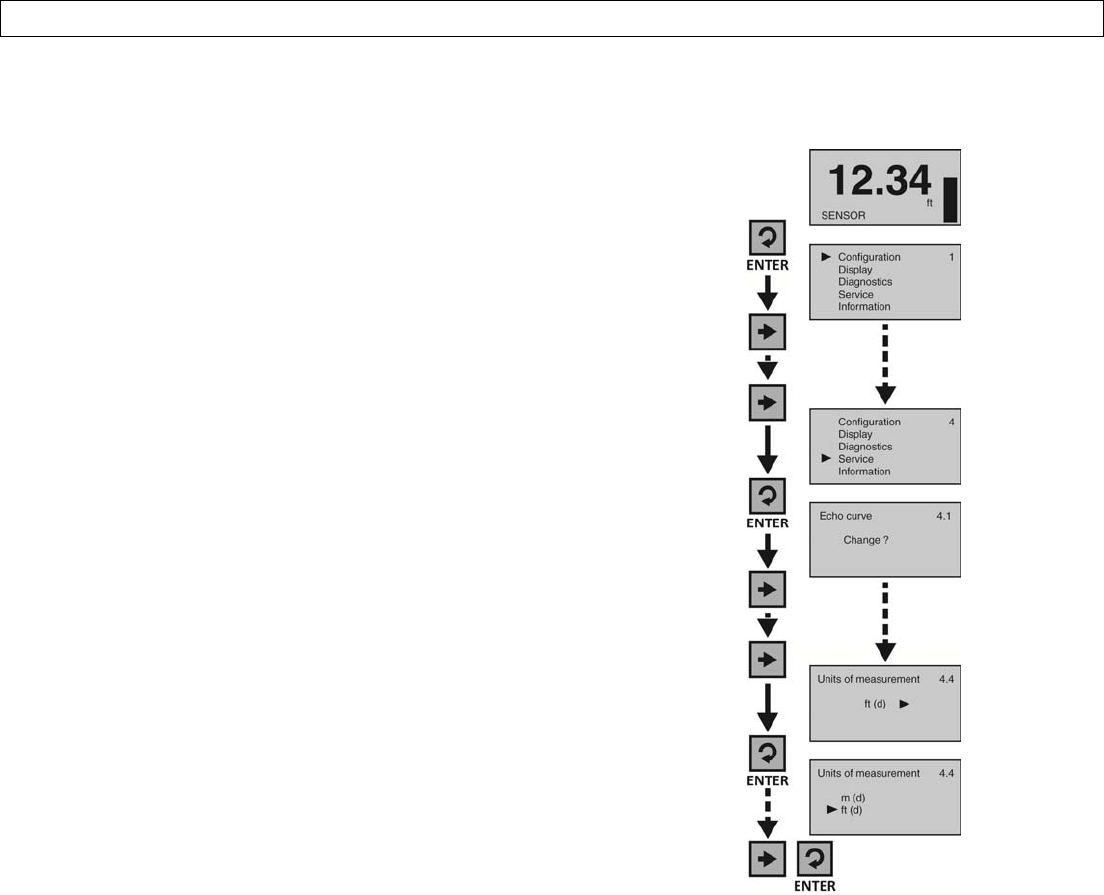
Step2‐SettheUnitsofMeasurement
Thisfunctionsetstheunitsforallmeasurementvaluestobeenteredintothesensor.
1. FromtheMainScreen,pressEntertoadvanceinto
theMainMenu.
2. PressRightArrowrepeatedlyuntilthearrowisnext
toService.
3. PressEntertoadvanceintotheServicemenu(and
Echocurvewillappear).
4. PressRightArrowrepeatedlyuntilthemenushows
UnitsofMeasurement.
5. PressEntertoadvanceintoUnitsofMeasurement.
6. PressRightArrowtochangethesettingbetween
feet[ft(d)]andmeters[m(d)].
7. Whentheunitsarecorrect,pressEntertosavethe
setting.
8. Whendone,pressESCtoreturntotheMainMenu,
andpressESCasecondtimetoreturntotheMain
Screen.
UNRELEASED
Rev9_4MN301700Page35of72
CONFIGURATIONSectionFive
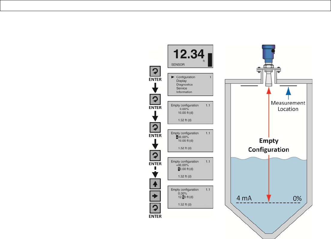
Step3‐SettheEmptyConfiguration(4mA)
ThisfunctionsetstheEmptyConfigurationpointforthesensorcorresponding4mAtoempty.
1. FromtheMainScreen,pressEnterto
advanceintotheMainMenu.
2. PressEntertoadvanceintothe
ConfigurationMenu.
3. PressEntertoadvanceintoEmpty
Configuration.Thefirstpercentage
segmentwillbehighlighted.
4. PressEnteragaintoswitchtothe
distance(d)setting.
5. PressRightArrowtomoveone
segmenttotheright.RightArrow
willscrolllefttorightandthenback
tothefirstsegment.
6. PressUpArrowtoincreasethevalue
ofthenumberhighlighted.UpArrow
willscrollfrom0to9andbackagain.
7. Whenthevalueiscorrect,press
Entertosavethesetting.
8. Whendone,pressESCtoreturnto
theMainMenu,andpressESCa
secondtimetoreturntotheMain
Screenor;Ifyouwanttoadvance
directlyintoFullConfiguration,press
RightArrow.
UNRELEASED
Page36of72MN301700Rev9_4
CONFIGURATIONSectionFive
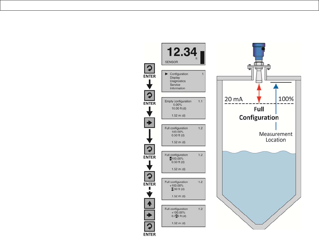
Step4‐SettheFullConfiguration(20mA)
ThisfunctionsetstheFullConfigurationpointforthesensorcorresponding20mAtofull.
1. FromtheMainScreen,pressEnterto
advanceintotheMainMenu.
2. PressEntertoadvanceintothe
ConfigurationMenu.
3. PressRightArrowtoadvanceinto
FullConfiguration.
4. PressEntertoadvanceintoFull
Configuration.Thefirstpercentage
segmentwillbehighlighted.
5. PressEnteragaintoswitchtothe
distance(d)setting.
6. PressRightArrowtomoveone
segmenttotheright.RightArrow
willscrolllefttorightandthenback
tothefirstsegment.
7. PressUpArrowtoincreasethevalue
ofthenumberhighlighted.UpArrow
willscrollfrom0to9andbackagain.
8. Whenthevalueiscorrect,press
Entertosavethesetting.
9. Whendone,pressESCtoreturnto
theMainMenu,andpressESCa
secondtimetoreturntotheMain
Screenor;Ifyouwanttoadvance
directlyintoRange,pressRight
ArrowrepeatedlyuntilRange
appears.
UNRELEASED
Rev9_4MN301700Page37of72
CONFIGURATIONSectionFive
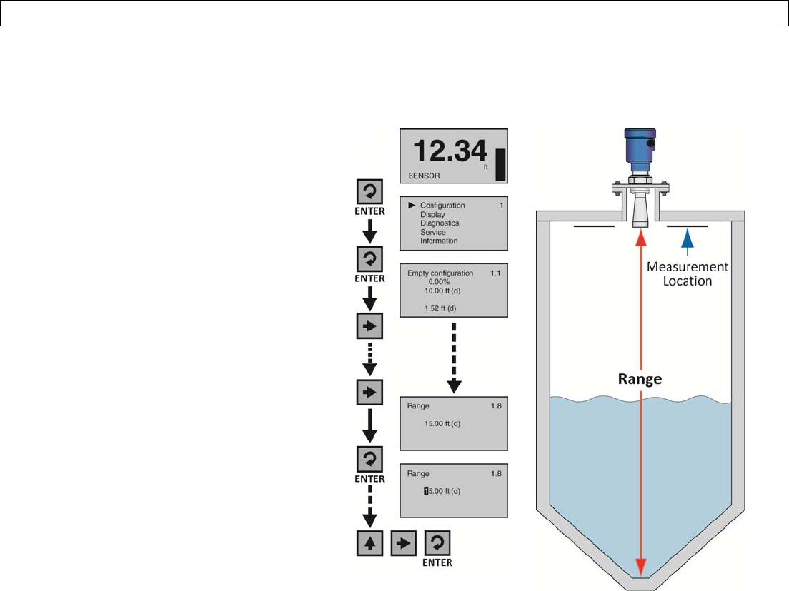
Step5‐SettheRange(MaximumRange)
Thisfunctionsetsthemaximumoperationalrange(MaxR)forthesensor.Thissettingdefinesthemaximumdistance
thatthesensorwilldetectvalidechoreturns.
1. FromtheMainScreen,pressEnterto
advanceintotheMainMenu.
2. PressEntertoadvanceintothe
ConfigurationMenu.
3. PressRightArrowrepeatedlyuntil
themenushowsRange.
4. PressEntertoeditRangevalue.The
firstsegmentwillbehighlighted.
5. PressRightArrowtomoveone
segmenttotheright.RightArrow
willscrolllefttorightandthenback
tothefirstsegment.
6. PressUpArrowtoincreasethevalue
ofthenumberhighlighted.UpArrow
willscrollfrom0to9andbackagain.
7. Whenthevalueiscorrect,press
Entertosavethesetting.
8. Whendone,pressESCtoreturnto
theMainMenu,andpressESCa
secondtimetoreturntotheMain
Screenor;ifyouwanttoadvance
directlyintoDeadBand,pressRight
ArrowrepeatedlyuntilDeadBand
appears.
UNRELEASED
Page38of72MN301700Rev9_4
CONFIGURATIONSectionFive
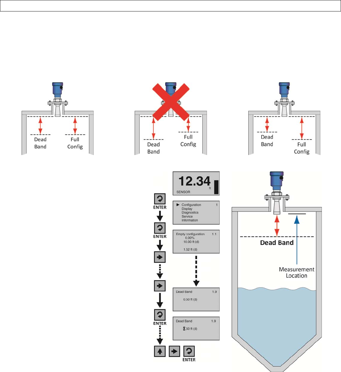
Step6‐SettheDeadBand
ThisfunctionsetstheDeadBandforthesensor.Thissettingdefinestheminimumdistancethatthesensorwilldetect
validechoreturns.WhiletheDeadBandsettingistypicallyconfiguredtobeequalwithorslightlyabove(higherinthe
tank)theFullConfigurationsetting(20mA),itsfunctionsindependentlyofFullConfiguration.Note:IftheDeadBand
settingisplacedbelowtheFullConfigurationsetting,thenthesensorwillnotmeasureabovetheDeadBand.
DeadBandEqualsFullConfig. DeadBandBelowFullConfig. DeadBandAboveFullConfig.
1. FromtheMainScreen,pressEnterto
advanceintotheMainMenu.
2. PressEntertoadvanceintothe
ConfigurationMenu.
3. PressRightArrowrepeatedlyuntil
menushowsDeadBand.
4. PressEntertoeditDeadBandvalue.
Thefirstsegmentwillbehighlighted.
5. PressRightArrowtomoveone
segmenttotheright.RightArrow
willscrolllefttorightandthenback
tothefirstsegment.
6. PressUpArrowtoincreasethevalue
ofthenumberhighlighted.UpArrow
willscrollfrom0to9andbackagain.
7. Whenthevalueiscorrect,press
Entertosavethesetting.
8. Whendone,pressESCtoreturnto
theMainMenu,andpressESCa
secondtimetoreturntotheMain
Screen.
UNRELEASED
Rev9_4MN301700Page39of72
CONFIGURATIONSectionFive
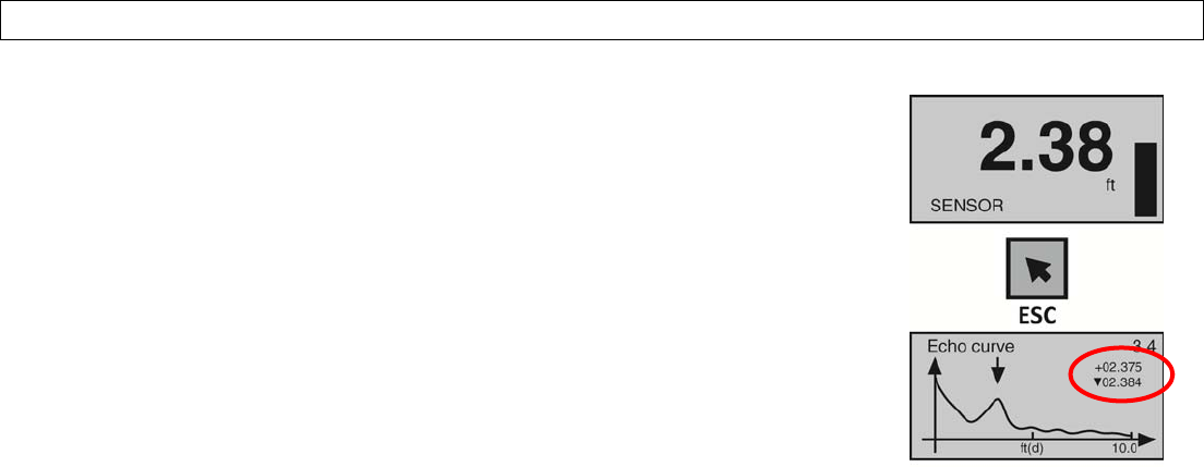
Step7‐ChecktheEchoCurve
Thisfunctiondisplaystheprimaryechoreturn(s)thatthesensorisseeinggraphically,
thelocationandamplitudeofthereturn(s),andthenumericairgapdistancefromthe
sensor’smeasurementlocationtotheliquidlevelbelow.Note:Thisstepshouldonly
beperformedafterhavingcompletedthepriorsixconfigurationstepswiththesensor
installedonthetank.Additionally,ifthesensorwasinstalledinastandpipeorsight
glass,nowgoforwardtoSectionSixandturnonthestillwellfunction(Sensor
InstalledinaStandPipeorSightGlass)beforecontinuingwiththisstep.
1. FromtheMainScreen,pressESCandtheEchoCurveScreenwillappear.The
curvegraphicallyrepresentstheprimaryechoreturn(s)amplitude(Y‐axis)
overdistance(X‐axis).Abovetheechoreturnpeakisafloatingarrowand
trianglesymbol(whichundernormalconditionsareoftenmergedtogetheror
seenasasingletrianglebecauseit’sthelargerofthetwosymbols).The
arrowrepresentsthemeasuredliquidlevelandthetrianglerepresentsthe
peakamplitudelocationoftheechoreturn.Undernormalconditions,expect
toseeastabletriangle(oroverlappingarrowandtriangle)floatingabovea
pronouncedpeakattheexpectedairgapdistancebetweenthemeasurement
locationandliquidlevel.
2. Intheupperrighthandcornerofthescreenaretwolinesofnumbersthat
representtheairgapdistancefromthemeasurementlocationtotheliquid
level(arrow)onthetop,andpeakamplitudelocation(triangle)oftheecho
returnonthebottom.Undernormalconditions,thesevaluesshouldbe
relativelyclosetooneanotherandconsistentwiththeexpectedairgap
distancebetweenthemeasurementlocationandliquidlevel.
3. Assumingthatthesensorisproperlyinstalled,ifthemeasuredliquidleveland
peakamplitudelocationdata(symbolsandvalues)areunstable,substantially
differentfromoneanotherand/orinconsistentwiththeactualairgap
distance,thenthislikelyindicatesthatthesensorrequiresadditionalprocess
adjustment(s)describedinthefollowingSectionSix.
4. Whendone,pressESCtoreturntotheMainMenu.
UNRELEASED
Page40of72MN301700Rev9_4
PROCESSADJUSTMENTSSectionSix
ProcessAdjustmentsOverview
Theseoptionalfunctionsareintendedtoimprovesensorperformanceinapplicationswiththebelowprocessand/or
installationcharacteristics.Note:Theseadjustmentsshouldonlybeperformedwhen(afterhavingcompletedtheseven
configurationstepsdescribedinSectionFivewiththesensorinstalledonthetank)thesensorisnotperformingtoyour
satisfaction.Whereso,performthefollowingapplicableProcessAdjustments.
1. FastFillingorEmptyingoftheLiquid
2. LiquidSurfaceisTurbulentorAgitatedSurface
3. FoamontheSurfaceoftheLiquid
4. SensorInstalledinaStandPipeorSightGlass
UNRELEASED
Rev9_4MN301700Page41of72
PROCESSADJUSTMENTSSectionSix
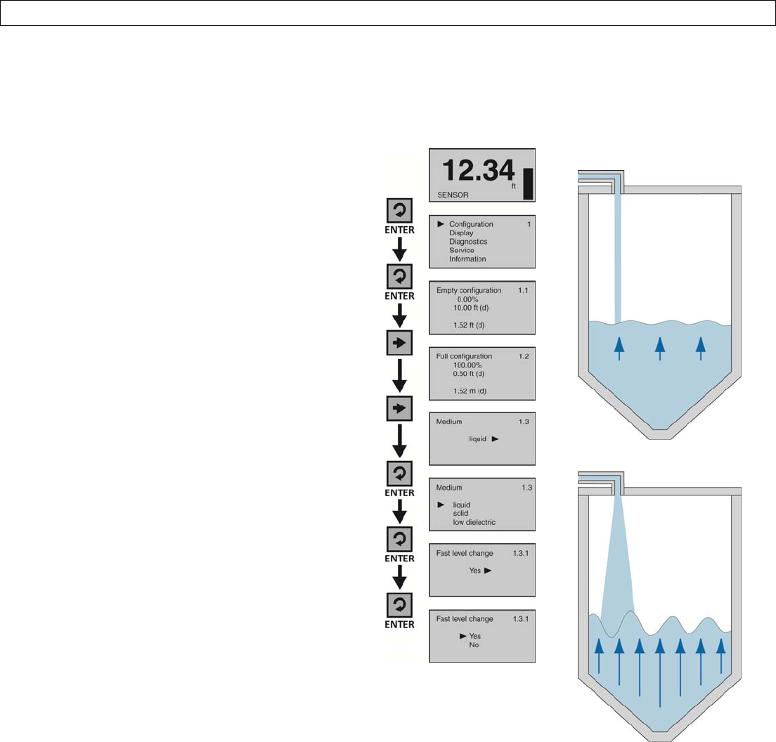
FastFillingorEmptyingofLiquid
Ifthespeedofliquidlevelriseorfallwithinthetankisgreaterthanarateof1”persecond(25.4mm/sec),setFastLevel
ChangetoYes.Note:Fastfillingoremptyingcanoccurwhenmultiplepumpsareoperatingorwhenaweatherevent
increasestheamountofliquidenteringthetank.
1. FromtheMainScreen,pressEntertoadvance
intotheMainMenu.
2. PressEntertoadvanceintotheConfiguration
Menu.
3. PressRightArrowtoadvancefromEmpty
ConfigurationtoFullConfiguration.
4. PressRightArrowtoadvancefromFull
ConfigurationtoMedium.
5. PressEntertoadvanceintoMedium.Liquid,
Solid,LowDielectricwillappear.
6. PressEntertoadvanceintoLiquid.FastLevel
Changewillappearfirst.
7. PressEntertoadvanceintoFastLevelChange.
8. PressRightArrowtochangetheFastLevel
Changesetting.
9. Whenthesettingiscorrect,pressEnterto
save.
10. Whendone,pressESCtoreturntoMedium,
pressESCagaintoreturntotheConfiguration
Menu,andpressESCathirdtimetoreturnto
theMainScreenor;Ifyouwanttoadvance
directlyintoTurbulentSurface,pressRight
ArrowrepeatedlyuntilTurbulentSurface
appears.
NormalLevelChange
FastLevelChange
UNRELEASED
Page42of72MN301700Rev9_4
PROCESSADJUSTMENTSSectionSix
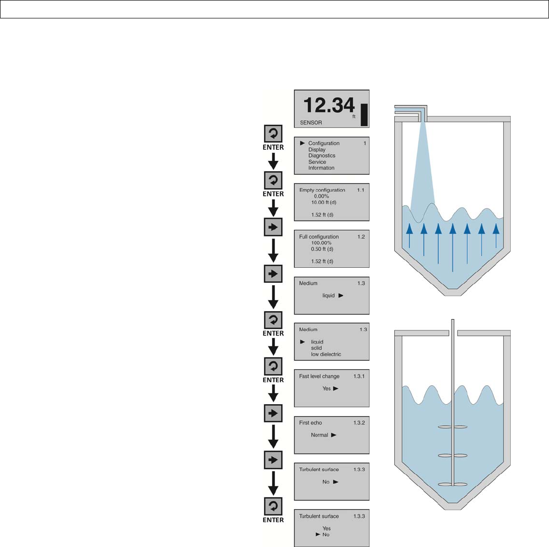
LiquidSurfaceisTurbulentorAgitated
Iftheliquidsurfaceisturbulentoragitated,setTurbulentSurfacetoYes.Note:Turbulentoragitatedsurfacescan
occurwhentanksarefilledfromthetopwithoutadownpipe,orwhenamixerorairagitationisusedwithinthetank.
1. FromtheMainScreen,pressEnterto
advanceintotheMainMenu.
2. PressEntertoadvanceintothe
ConfigurationMenu.
3. PressRightArrowtoadvancefrom
EmptyConfigurationtoFull
Configuration.
4. PressRightArrowtoadvancefromFull
ConfigurationtoMedium.
5. PressEntertoadvanceintoMedium.
Liquid,Solid,LowDielectricwillappear.
6. PressEntertoadvanceintoLiquid.Fast
LevelChangewillappearfirst.
7. PressRightArrowtoadvancefromFast
LevelChangetoFirstEcho.
8. PressRightArrowtoadvancefromFirst
EchotoTurbulentSurface.
9. PressEntertoadvanceintoTurbulent
Surface.
10. PressRightArrowtochangethe
TurbulentSurfacesetting.
11. Whenthesettingiscorrect,pressEnter
tosave.
12. Whendone,pressESCtoreturnto
Medium,pressESCagaintoreturnto
theConfigurationMenu,andpressESCa
thirdtimetoreturntotheMainScreen
or;Ifyouwanttoadvancedirectlyinto
Foam,pressRightArrowrepeatedly
untilFoamappears.
TurbulencefromTankFill
AgitationfromMixer
UNRELEASED
Rev9_4MN301700Page43of72
PROCESSADJUSTMENTSSectionSix
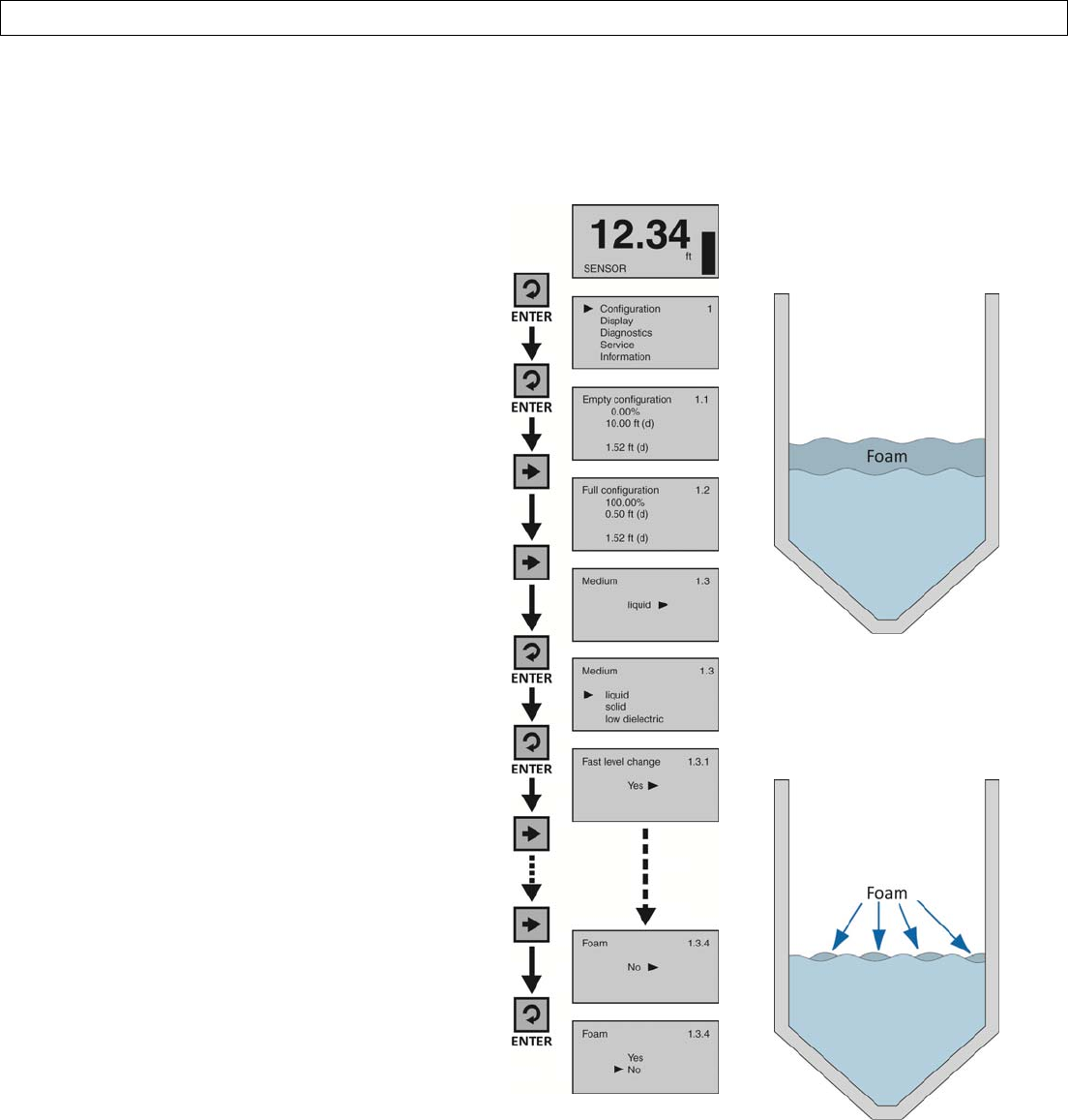
FoamontheSurfaceoftheLiquid
Iftheentireliquidsurfaceiscoveredwithfoam,setFoamtoYes.Thisisnotnecessaryiftheliquidsurfaceispartially
coveredwithfoam.Note:Foamcanoccurwhentanksarefilledfromthetopwithoutadown‐fillpipe,orwhenamixer
orairagitationisusedwithinthetank.
1. FromtheMainScreen,pressEntertoadvance
intotheMainMenu.
2. PressEntertoadvanceintotheConfiguration
Menu.
3. PressRightArrowtoadvancefromEmpty
ConfigurationtoFullConfiguration.
4
. PressRightArrowtoadvancefromFull
ConfigurationtoMedium.
5. PressEntertoadvanceintoMedium.Liquid,
Solid,LowDielectricwillappear.
6. PressEntertoadvanceintoLiquid.FastLevel
Changewillappearfirst.
7. PressRightArrowrepeatedlyuntilFoam1.3.4
appears.
8. PressEntertoadvanceintoFoam.
9. PressRightArrowtochangetheFoam
setting.
10. Whenthesettingiscorrect,pressEnterto
save.
11. Whendone,pressESCtoreturntoMedium,
pressESCagaintoreturntotheConfiguration
Menu,andpressESCathirdtimetoreturnto
theMainScreenor;Ifyouwanttoadvance
directlyintoStillWell,pressRightArrow
repeatedlyuntilStillWellappears.
HeavyFoam–Iffoamcovers
theentiresurfaceofthe
liquid,setFoamtoYes.
LightFoam–Iffoampartially
coversthesurfaceofthe
liquid,setFoamtoNo.
UNRELEASED
Page44of72MN301700Rev9_4
PROCESSADJUSTMENTSSectionSix
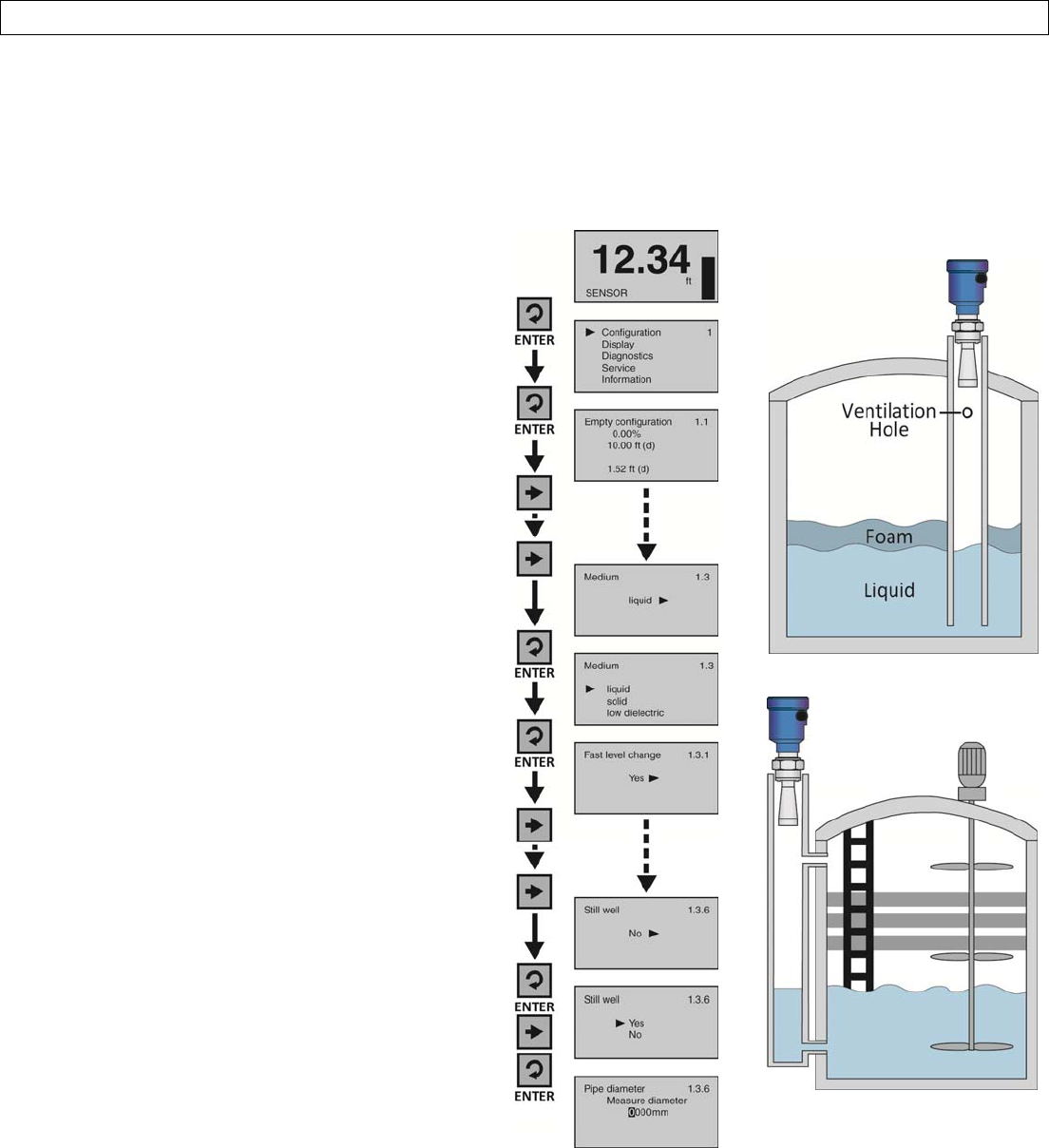
SensorInstalledinaStandPipeorSightGlass
Ifthesensorisinstalledinametalstandpipe(stillwell)ormetalsightglass,setStillWelltoyesandentertheinnerPipe
Diameterdimension.Note:ThePipeDiameterwillbeenteredinmillimeters.Forexample,a3”pipecanhaveaninner
diameterof3.042”.Toconvertinchestomm,multipleinchesby25.4mm.Thus,a3.042”pipeinnerdiameterequals
77.26mm.Youwouldthenenterthevalueof77mm.
1. FromtheMainScreen,pressEntertoadvance
intotheMainMenu.
2. PressEntertoadvanceintotheConfiguration
Menu.
3. PressRightArrowrepeatedlyuntilmenushows
Medium.
4. PressEntertoadvanceintoMedium.Liquid,
Solid&LowDielectricwillappear.
5. PressEntertoadvanceintoLiquid.FastLevel
Changewillappearfirst.
6. PressRightArrowrepeatedlyuntilStillWell
appears.
7. PressEntertoadvanceintoStillWell.
8. PressRightArrowtochangethesettingfrom
NotoYes.
9. PressEntertoenterthePipeDiameter.
10. UsetheRightArrowtomoveonesegmentto
theright.RightArrowwillscrolllefttoright
andthenbacktothefirstsegment.
11. UsetheUpArrowtoincreasethevalueofthe
numberhighlighted.UpArrowwillscrollfrom0
to9andbackagain.
12. Whenthevalueiscorrect,pressEntertosave.
13. Whendone,pressESCtoreturntoMedium,
pressESCagaintoreturntotheConfiguration
Menu,andpressESCathirdtimetoreturnto
theMainScreen.
StillWellorStandPipe
SightGlass
UNRELEASED
Rev9_4MN301700Page45of72
ADVANCEDADJUSTMENTSSectionSeven
AdvancedAdjustmentsOverview
Theseoptionalfunctionsareusedtochangethesensoroutputcharacteristics,orCreateaFalseEchoCurvetofilterout
falseechoreturnswithinthetank(improvingsensorperformance),orUpdateanexistingFalseEchoCurvefilterifthe
originalfilterwasnotcreatedduringanemptytankcondition.
1. 4‐20mARevOutput‐
Reversesthe
currentoutputfrom4mA@bottom
and20mA@topoftankto20mA@
bottomand4mA@topofthetank.
2. Fail‐Safe‐Allowsforthepresettingof
thecurrentoutputwhenasensor
failureoccurs.Optionsarenochange
tocurrent,20.5mAor22mA.
3. MinimumCurrent‐Setstheminimum
currentoutputforthesensor.Options
are4.0mAor3.9mA.
4. CreateanewFalseEchoCurve‐A
methodtofilteroutfalseechoreturns
withinthetank.Thisshouldbe
performedwhenthetankisatits
lowestlevel(empty).
5. UpdateanexistingFalseEchoCurve‐
AmethodtoupdateanexistingFalse
EchoCurvetoincludealowersection
ofthetankthatwasnotexposed
duringthecreationoftheoriginal
EchoCurve.Note:Ifyoudon'tknow
thelocation(levelposition)orvalidity
oftheoriginalFalseEchoCurve,itis
recommendedtodeletetheoriginal
EchoCurve,andthencreateanew
FalseEchoCurve(versusupdatingan
existingFalseEchoCurve).
UNRELEASED
Page46of72MN301700Rev9_4
ADVANCEDADJUSTMENTSSectionSeven
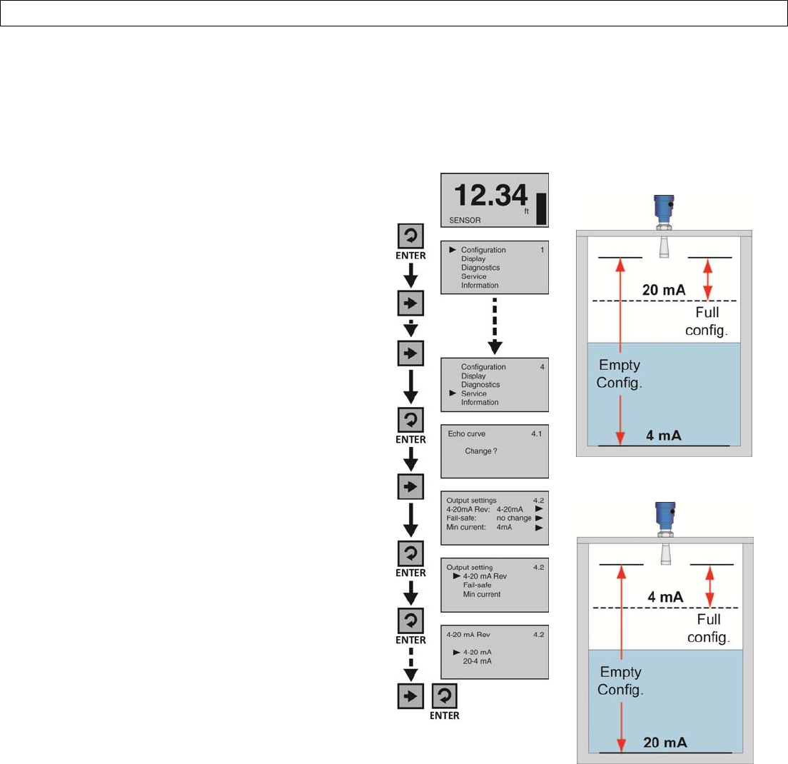
4‐20mAReverseOutput
Thisfunctionsetsthecurrentoutputateither4‐20mAor20‐4mA.Selecting4‐20mAsetstheoutputwith4mA@
bottomand20mA@topofthetank.Thisisthestandardoutputusedinthemajorityofapplications.Selecting20‐4mA
setstheoutputwith20mA@bottomand4mA@topofthetank.Thisisanoptionaloutputsometimesusedin
applicationswherethelevelismaintainedatahighlevel.
1. FromtheMainScreen,pressEnterto
advanceintotheMainMenu.
2. PressRightArrowrepeatedlyuntilthearrow
isnexttoService.
3. PressEntertoadvanceintoServiceMenu.
4. PressRightArrowtomovefromEchoCurve
toOutputCurrent.
5. PressEntertoadvanceintoOutputCurrent.
6. PressEntertoadvanceinto4‐20mARev.
7. PressRightArrowtochangethesetting
between4‐20mAand20‐4mA.
8. Whenthesettingiscorrect,pressEnterto
save.
9. Whendone,pressESCtoreturntothe
ServiceMenuandpressESCasecondtimeto
returntotheMainScreenor;ifyouwantto
advancedirectlyintoFail‐Safe,pressEnter
andthenRightArrowuntilFail‐Safeappears.
4to20mAOutput
20to4mAOutput
UNRELEASED
Rev9_4MN301700Page47of72
ADVANCEDADJUSTMENTSSectionSeven
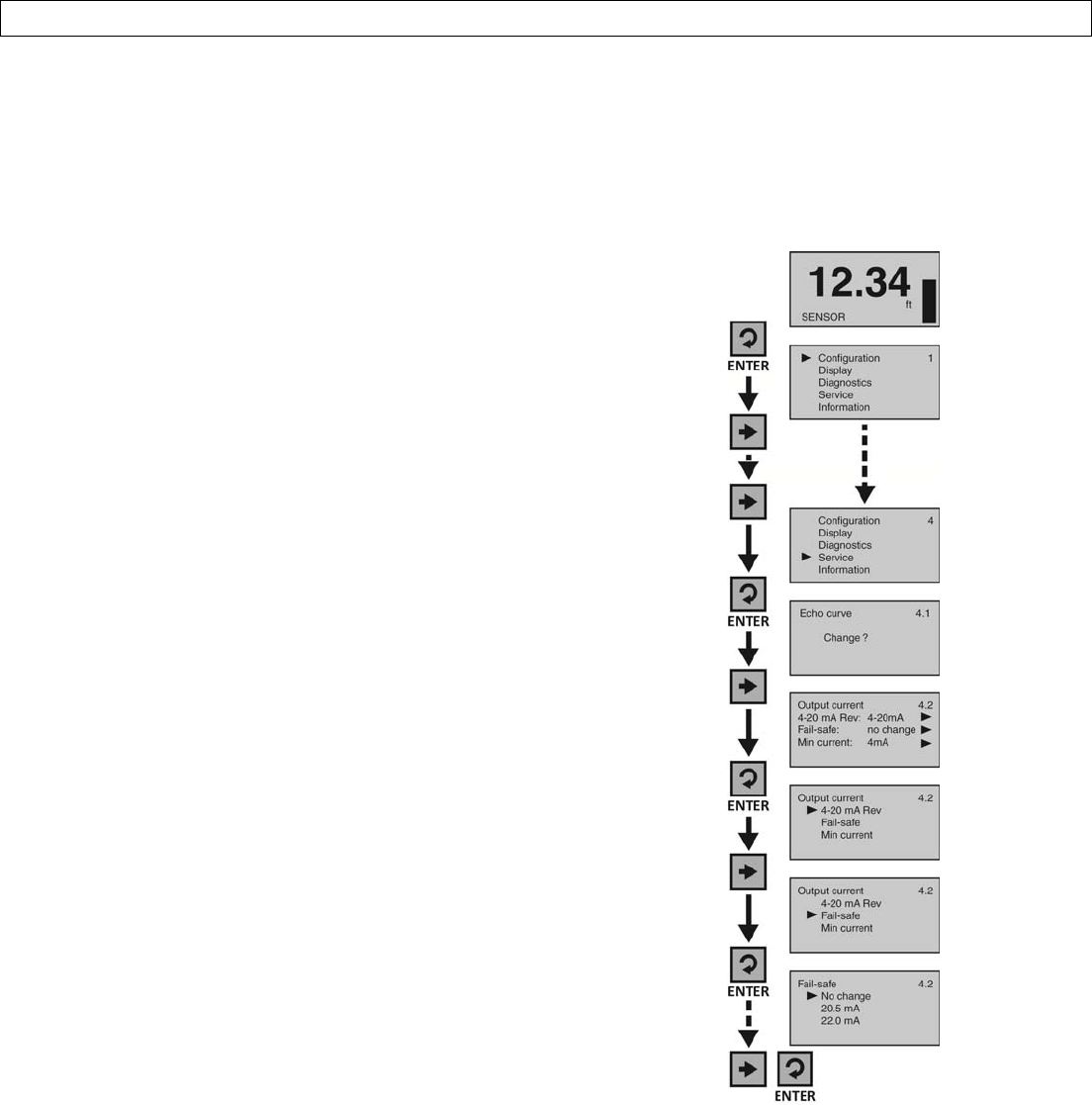
Fail‐SafeOutput
Thisfunctionisusedtosetthecurrentoutputtoadesignatedstateifthesensorlosesmeasurementconfidence.
SelectingNoChangewillholdthecurrentatitslastvalidcurrentoutput.Selecting20.5mAwillforcethecurrenttojump
to20.5mA.Selecting22.5mAwillforcethecurrenttojumpto22.5mA.Note:Thelattertwohighcurrentoutputstates
areabovethestandard4‐20mAoperationalrange,andcanbeusedtoindicatethatafailurehasoccurred.
1. FromtheMainScreen,pressEntertoadvanceinto
theMainMenu
2. PressRightArrowrepeatedlyuntilthearrowisnext
toService.
3. PressEntertoadvanceintoServiceMenuandEcho
Curvewillappear.
4. PressRightArrowtomovefromEchoCurveto
OutputCurrent.
5. PressEntertoadvanceintoOutputCurrentmenu.
6. PressRightArrowtomovefromReverse4‐20mAto
Fail‐safe.
7. PressEntertoenterFail‐safe.
8. PressRightArrowtochangethesettingbetweenNo
change,20.5mAand22.0mA.
9. Whenthesettingiscorrect,pressEntertosave.
10. Whendone,pressESCtoreturntotheServiceMenu
andpressESCasecondtimetoreturntotheMain
Screenor;ifyouwanttoadvancedirectlyintoMin
Current,pressEnterandthenRightArrowuntilMin
Currentappears.
UNRELEASED
Page48of72MN301700Rev9_4
ADVANCEDADJUSTMENTSSectionSeven
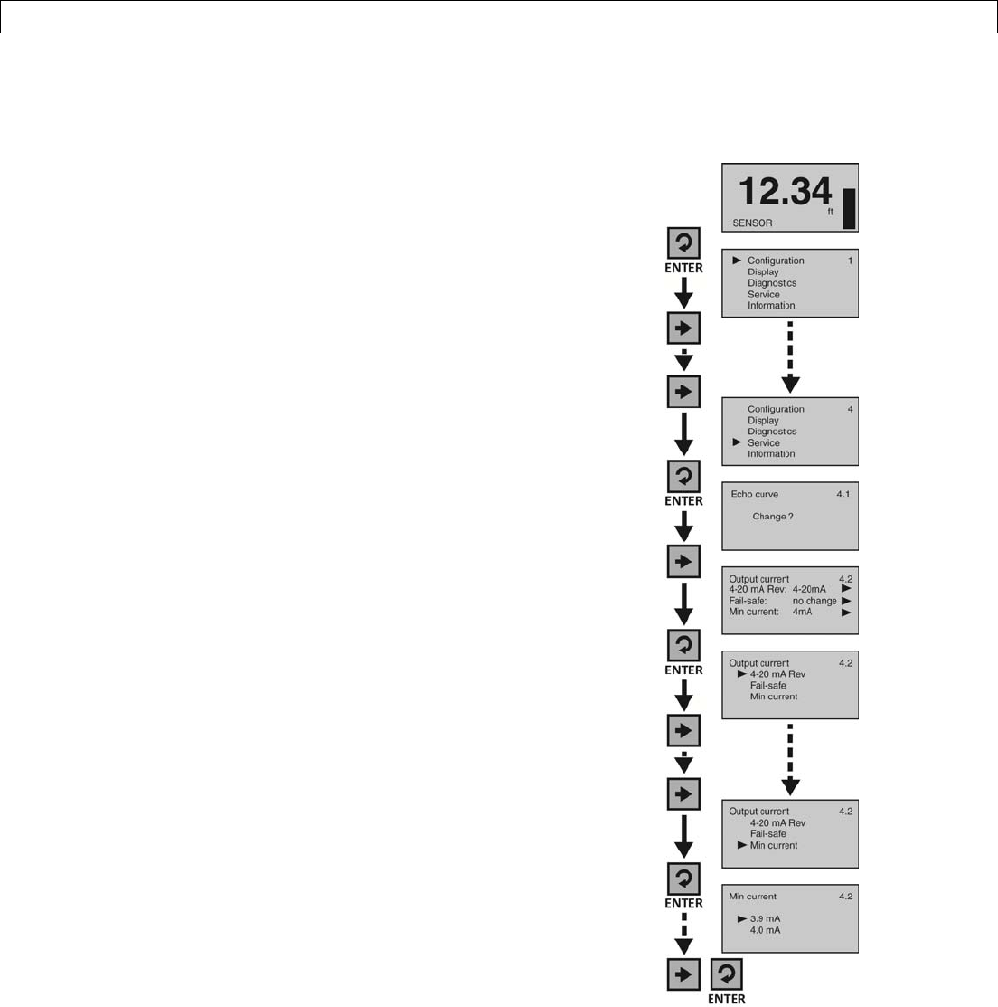
MinimumCurrentOutput
Thisfunctionsetstheminimumcurrentoutputforthesensorateither4.0mAor3.9mA.Note:4.0mAisthedefault
minimumcurrentoutputandisusedinthemajorityofapplications.
1. FromtheMainScreen,pressEntertoadvanceinto
theMainMenu.
2. PressRightArrowrepeatedlyuntilthearrowisnext
toService.
3. PressEntertoadvanceintoServiceMenuandEcho
Curvewillappear.
4. PressRightArrowtomovefromEchoCurveto
OutputCurrent.
5. PressEntertoadvanceintoOutputCurrentmenu.
6. PressRightArrowrepeatedlytomovefromReverse
4‐20mAtoMinCurrent.
7. PressEntertoenterMinCurrent.
8. PressRightArrowtochangethesettingbetween
3.9mAand4.0mA.
9. Whenthesettingiscorrect,pressEntertosave.
10. Whendone,pressESCtoreturntotheServiceMenu
andpressESCasecondtimetoreturntotheMain
Screen.
UNRELEASED
Rev9_4MN301700Page49of72
ADVANCEDADJUSTMENTSSectionSeven
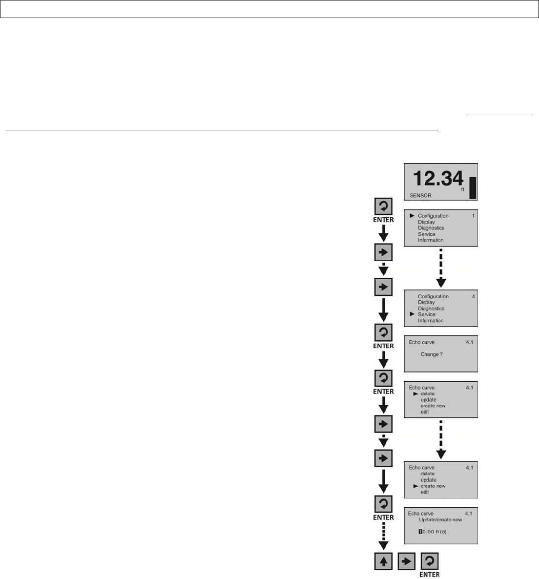
CreateaNewFalseEchoCurve
Obstructionsinthetank(mixerblades,sidewallweldjointsormaterialbuild‐up,submersiblepumps,piping,other
apparatus)ortalltankrisersorinstallationfittingscancreatefalseechoreturnsthatimpairthesensor’smeasurement.
Thisfunctionmapsallechoreturnswithinthetank,differentiatingbetweengoodandfalseechoes,andstoresthose
identifiedasfalseintotheFalseEchoCurve,sotheywillnotbeconsideredinthelevelmeasurement.Note:AFalse
EchoCurveshouldonlybeperformedwhenthetankisemptysothatallfalsereflectionswillbedetected.Beforestarting,
measureandnotetheexactdistancefromthesensor’smeasurementlocationtotheliquidsurface.Settingthedistance
valuetoolargeortooshortcanforcethesensorintoignoringthetruelevel.
1. FromtheMainScreen,pressEntertoadvanceintotheMain
Menu.
2. PressRightArrowrepeatedlyuntilthearrowisnextto
Service.
3. PressEntertoadvanceintoServiceMenuandEchoCurvewill
appear.
4. PressEntertomakeachangetotheEchoCurvesettings.
5. PressRightArrowrepeatedlyuntilthearrowisnexttoCreate
New.
6. PressEntertoadvanceintoCreateNew.Enterthedistance
fromthesensor’smeasurementlocationtotheliquidsurface.
7. UsetheRightArrowtomoveonesegmenttotheright.The
RightArrowwillscrolllefttorightandthenbacktothefirst
segment.
8. UsetheUpArrowtoincreasethevalueofthenumber
highlighted.TheUpArrowwillscrollfrom0to9andback
again.
9. Whenthevalueiscorrect,pressEntertosavethesettingand
begintheFalseEchoCurvemapping.Theprocessmaytakea
fewminutes.Whencomplete,thedisplaywillreturntothe
EchoCurvescreen.
10. Whendone,pressESCtoreturntotheServiceMenuand
pressESCasecondtimetoreturntotheMainScreen.
11. FromtheMainScreen,pressESCandtheEchoCurveScreen
willappear.FollowtheCheckEchoCurveprocedure
describedattheendofSectionFivetoconfirmthatthe
sensorisperformingcorrectly.
UNRELEASED
Page50of72MN301700Rev9_4
ADVANCEDADJUSTMENTSSectionSeven
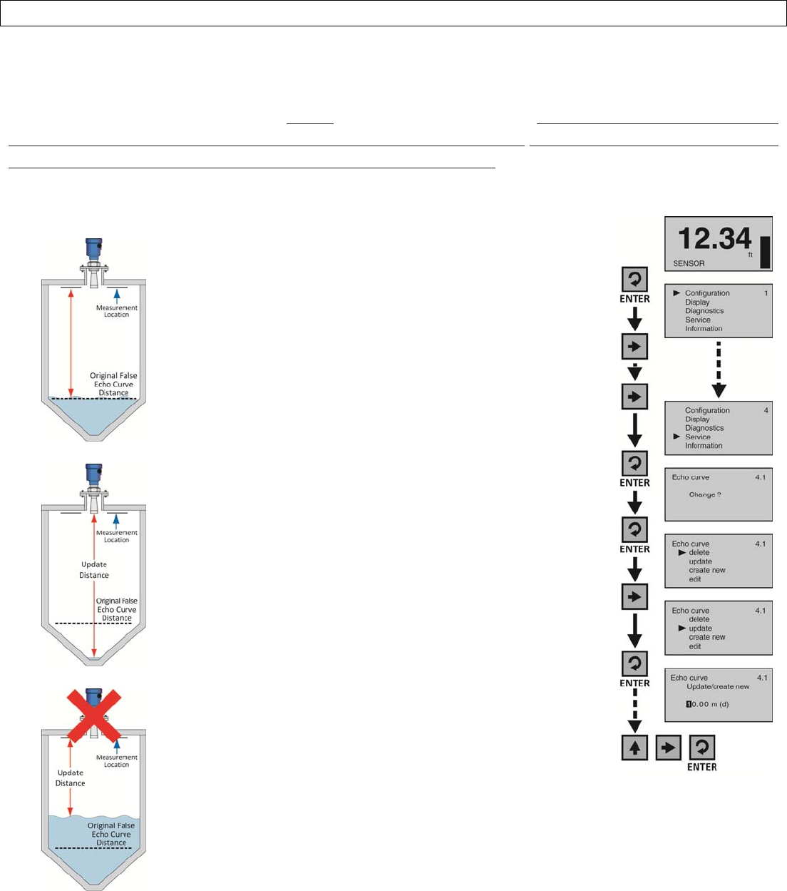
UpdateanExistingFalseEchoCurve
ThisfunctionenablesanExistingFalseEchoCurvetobeupdatedunderthecircumstancesthatthecurvewascreated
whenthelevelwashigherthananemptytankcondition.Note:Thisfunctionshouldonlybeperformedtoupdatean
ExistingFalseEchoCurvewhenthelevelisBELOWtheoriginalFalseEchoCurve.Donotusethisfunctiontoupdatean
ExistingFalseEchoCurvewhenthelevelisabovetheoriginalFalseEchoCurve.Beforestarting,measureandnotethe
exactdistancefromthesensor’smeasurementlocationtotheliquidsurface.Settingthedistancevaluetoolargeortoo
shortcanforcethesensorintoignoringthetruelevel.
OriginalFalseEchoCurve
1. FromtheMainScreen,pressEntertoadvanceintothe
MainMenu.
2. PressRightArrowrepeatedlyuntilthearrowisnextto
Service.
3. PressEntertoadvanceintoServiceMenuandEcho
Curvewillappear.
4. PressEntertomakeachangetotheEchoCurve
settings.
5. PressRightArrowrepeatedlyuntilthearrowisnextto
Update.
6. PressEntertoadvanceintoUpdate.Entertheactual
distancefromthesensor’smeasurementlocationto
theliquidsurface.
7. UsetheRightArrowtomoveonesegmenttothe
right.TheRightArrowwillscrolllefttorightandthen
backtothefirstsegment.
8. UsetheUpArrowtoincreasethevalueofthenumber
highlighted.TheUpArrowwillscrollfrom0to9and
backagain.
9. Whenthevalueiscorrect,pressEntertosavethe
settingandbegintheFalseEchoCurvemapping.The
processmaytakeafewminutes.Whencomplete,the
displaywillreturntotheEchoCurvescreen.
10. Whendone,pressESCtoreturntotheServiceMenu
andpressESCasecondtimetoreturntotheMain
Screen.
11. FromtheMainScreen,pressESCandtheEchoCurve
Screenwillappear.FollowtheCheckEchoCurve
proceduredescribedattheendofSectionFiveto
confirmthatthesensorisperformingcorrectly.
GoodUpdate
BadUpdate
UNRELEASED
Rev9_4MN301700Page51of72
TROUBLESHOOTINGSectionEight
TroubleshootingOverview
Thesefunctionsprovidetroubleshootinginformation;enableEchoCurveadjustmentsanddeletionofsettings.
1. MeasurementStatus
1. Displaysthesignalstrength(dB)oftheechoreturnsandthefunctionalstatusofthesensorincluding
diagnosticerrorcodes.
2. PeakValues
1. Displaysthelowestandhighestlevelheightthatthesensorhasmeasuredindistance(d).
3. Simulation
1. Simulatesthe4‐20mAcurrentoutputfrompercentofspan,currentordistanceinputs.
4. FirstEchoAdjustment
1. ProvidestheabilitytoincreaseordecreasethepeaksignalstrengthoftheFirstEchoreturn.
5. EchoCurveZoom
1. ProvidestheabilitytozoominandmagnifytheEchoCurveoveraspecifiedrange.
6. FalseEchoCurveDelete
1. ProvidestheabilitytodeleteasavedFalseEchoCurve.
7. Reset
1. Providestheabilitytoresetconfigurationsettingsandmemory.
UNRELEASED
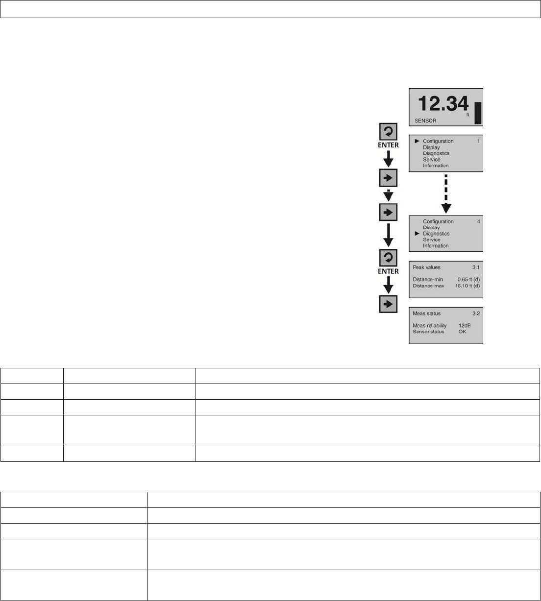
Page52of72MN301700Rev9_4
TROUBLESHOOTINGSectionEight
MeasurementStatus
Thisfunctiondisplaysthesignalstrength(dB)oftheechoreturnsandtheoperationalstatusofthesensorincluding
diagnosticerrorcodes.
1. FromtheMainScreen,pressEntertoadvanceintotheMain
Menu.
2. PressRightArrowrepeatedlyuntilthearrowisnextto
Diagnostics.
3. PressEntertoadvanceintoDiagnostics.
4. PressRightArrowtoswitchtoMeasurementStatus.
5. Measurementreliabilityindicatesthedecibel(dB)strengthof
RFenergythat’sreflectingbacktothesensorlessanynoise.
Forreliablefunction,thedBvalueshouldbe≥10dB.
6. Sensorstatusindicatesthefunctionalstatusofthesensor
(eitherOKorerrorcode)
7. Whendone,pressESCtoreturntotheServiceMenuand
pressESCasecondtimetoreturntotheMainScreen.
SensorStatusErrorCodes
ErrorCodeProblemSolution
E11InsufficientpowerCheckpowersupply
E12OpencircuitCheckwiringforopencircuit
E14Weakechoreturn(<10dB)Checkforobstaclesunderthesensor,eithercleartheobstacle,movethe
sensororperformaFalseEchoCurve
E15orE17ROMerrorContactyourdistributor
CurrentOutputConditions
ProblemSolution
Sensoroutput<3.9mA Checkwiringforopencircuit
Sensoroutput>22mACheckwiringforshortcircuit
Sensoroutputreaches4mA
beforethetankisempty
ChecktheEmptyConfigurationsetting,andifincorrect,extendthesettingtothe
emptytankposition
Sensoroutputwillnotreach
4mA
ChecktheRangesetting,andifincorrect,extendthesettingtoorslightlybelowthe
EmptyConfigurationsetting
UNRELEASED
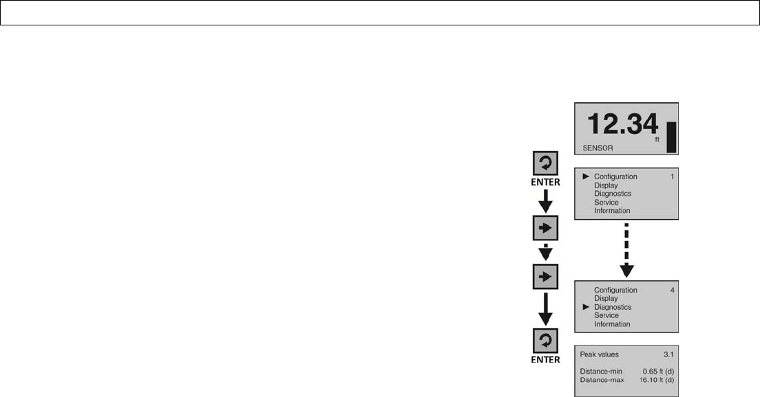
Rev9_4MN301700Page53of72
TROUBLESHOOTINGSectionEight
PeakValues
Thisfunctiondisplaysthelowestandhighestlevelheightthatthesensorhasmeasuredindistance(d).
1. FromtheMainScreen,pressEntertoadvanceintotheMain
Menu.
2. PressRightArrowrepeatedlyuntilarrowisnextto
Diagnostics.
3. PressEntertoadvanceintoDiagnosticsandviewPeakValues.
4. Distance‐ministhelowestmeasuredlevelandDistance‐maxis
thehighestmeasuredlevel.Confirmthatthesevaluesare
withinthesensor’soperationalrange.
5. Ifthevaluesappeartoohighortoolow,checkthetankfor
obstructionsthatcouldcausethatproblem.
6. Whendone,pressESCtoreturntotheServiceMenuand
pressESCasecondtimetoreturntotheMainScreen.
UNRELEASED
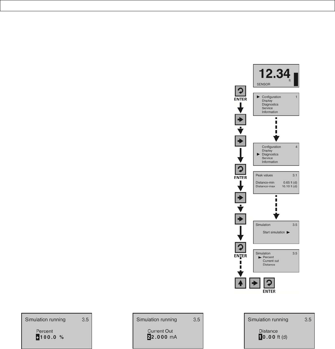
Page54of72MN301700Rev9_4
TROUBLESHOOTINGSectionEight
Simulation
Thisfunctionsimulatesthe4‐20mAcurrentoutput,whenthesensorisconfiguredandinstalledonthetank,butthe
levelcannotbechangedeasilyfortesting.Percent(ofspan),CurrentOutputorDistancecanbeusedastheinput
methodtosetthecurrentoutput.
1. FromtheMainScreen,pressEntertoadvanceintotheMain
Menu.
2. PressRightArrowrepeatedlyuntilthearrowisnextto
Diagnostics.
3. PressEntertoadvanceintoDiagnostics.
4. PressRightArrowrepeatedlyuntilSimulationappears.
5. PressEntertoadvanceintoSimulation.
6. UsetheRightArrowtoscrollamongthethreesimulation
methods(Percent,CurrentOutorDistance).
7. UseEntertoselectthemethodofsimulation.
8. Uponselectionofamethod,thesimulationwillstartandthe
currentoutputwillproportionatelyreflectthevalueshown.
Whilethesimulationisrunning,thevaluecanbechanged.
9. UsetheRightArrowtomoveonesegmenttotheright.The
RightArrowwillscrolllefttorightandthenbacktothefirst
segment.
10. UsetheUpArrowtoincreasethevalueofthenumber
highlighted.TheUpArrowwillscrollfrom0to9andback
again.
11. Whenthevalueiscorrect,pressEnterandthecurrentoutput
willreflectthevalueshown.
12. Whendone,pressESCtoreturntoSimulation,pressESC
againtoreturntotheConfigurationMenu,andpressESCa
thirdtimetoreturntotheMainScreen.
Percent CurrentOutput Distance
Thismethodusespercentageofspan
(0‐100%)tosetthecurrentoutput(4‐
20mA)betweentheEmptyandFull
Configurationvalueswith100%equal
to20mAand0%equalto4mA.
Thismethoddirectlysetsthecurrent
output(4‐20mA)tothedesiredvalue.
Thismethodusesdistancefromthe
sensor’smeasurementlocationtoset
thecurrentoutput(4‐20mA)between
theEmptyandFullConfiguration
values.
UNRELEASED
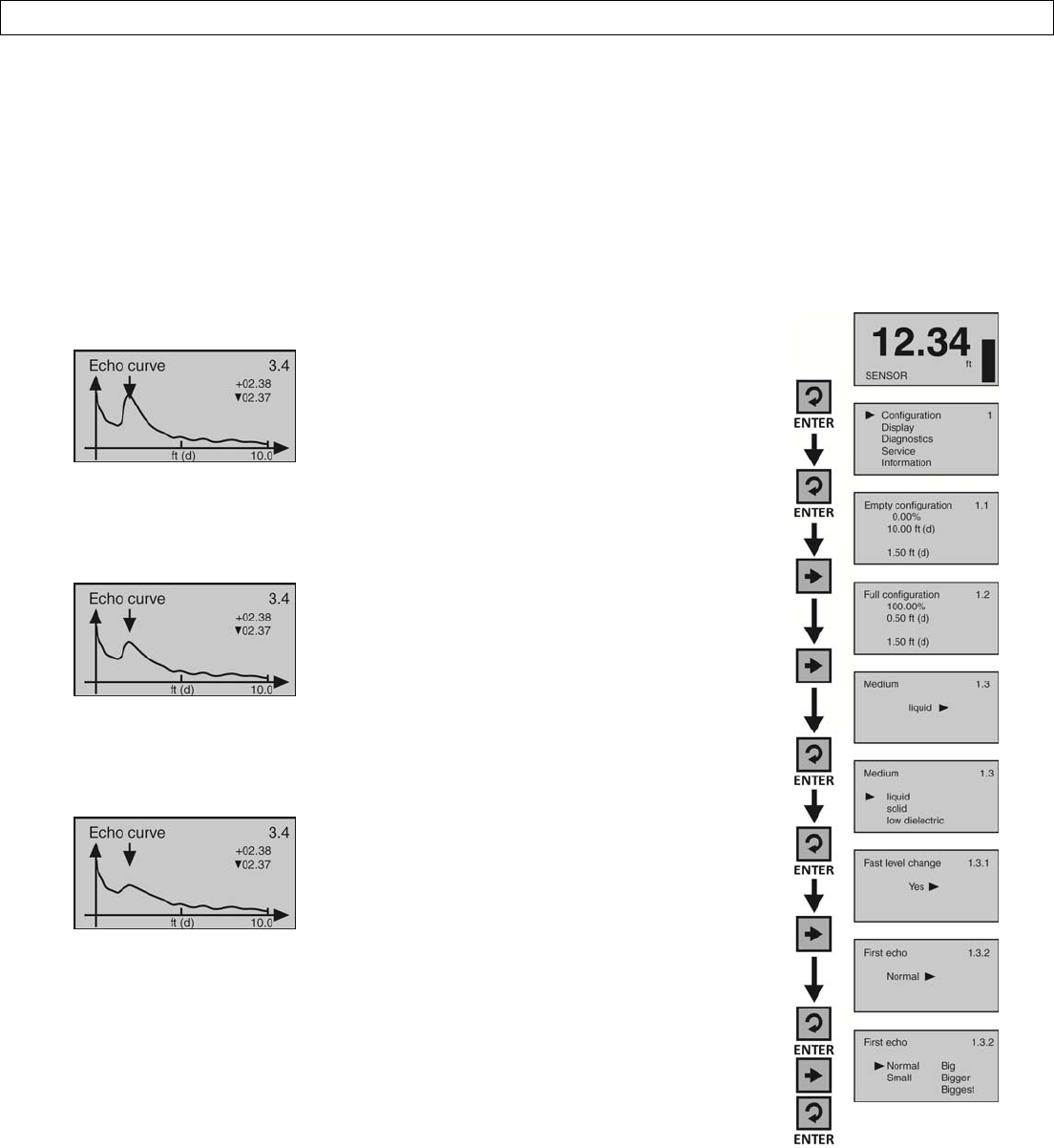
Rev9_4MN301700Page55of72
TROUBLESHOOTINGSectionEight
FirstEchoAdjustment
Thisfunctionincreasesordecreasesthepeakstrengthofthesensor’sFirstEchoreturn,andshouldonlybeperformedif:
1)Theliquidhasaveryhighdielectricconstantvalueandprimarilystaysinthenearfullrangeofthetank,resultingina
veryhighFirstEchopeakstrengthor;2)Processconditions,suchaswhentheliquidhasaverylowdielectricconstant
value,orwhenobstructions,heavyfoamorturbulenceexistinthetank,resultinginlittleornoFirstEchopeakstrength.
Note:Underconditionone(Example1),itcanbebeneficialtodecreasetheFirstEchopeakstrength.Undercondition
two(Example3),itcanbebeneficialtoincreasetheFirstEchopeakstrength.
Example11. FromtheMainScreen,pressEnterto
advanceintotheMainMenu.
2. PressEntertoadvanceintothe
ConfigurationMenu.
3. PressRightArrowtomovefromEmpty
ConfigurationtoFullConfiguration.
4. PressRightArrowtomovefromFull
ConfigurationtoMedium.
5. PressEntertoadvanceintoMedium
andLiquid,Solid&LowDielectricwill
appear.
6. PressEntertoadvanceintoLiquidand
FastLevelChangewillappear.
7. PressRightArrowtomovefromFast
LevelChangetoFirstEcho.
8. PressEntertoadvanceintoFirstEcho.
9. PressRightArrowtochangetheFirst
Echosetting.
10. Whensettingiscorrect,pressEnterto
save.
11. Whendone,pressESCtoreturnto
Medium,pressESCagaintoreturnto
theConfigurationMenu,andpressESC
athirdtimetoreturntotheMain
Screen.
FirstEchopeakisverystrongand
canbereduced.
Example2
FirstEchopeakisnormalandno
adjustmentisrequired.
Example3
FirstEchopeakisweakandcanbe
increased.
FirstEchoAdjustments
Normal‐Noadjustment
Small‐Decreaseby10dB
Big‐Increaseby10db
Bigger‐Increaseby20db
Biggest‐Increaseby40db
UNRELEASED
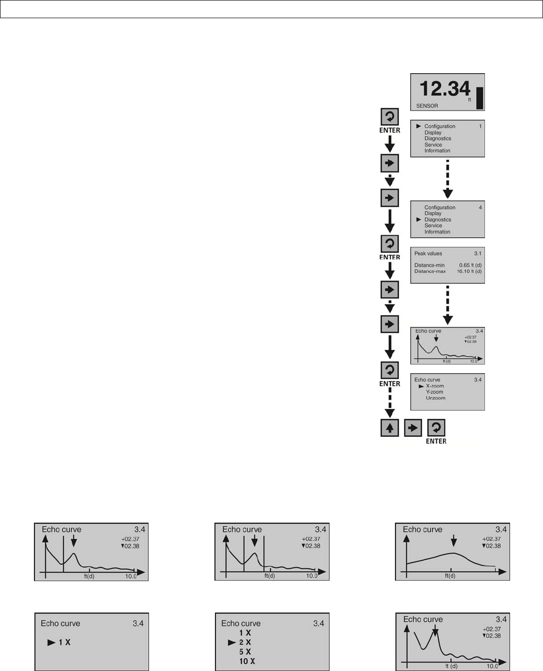
Page56of72MN301700Rev9_4
TROUBLESHOOTINGSectionEight
EchoCurveZoom
ThisfunctionzoomsinandmagnifiesanEchoCurveoveraspecifiedrange.
1. FromtheMainScreen,pressEntertoadvanceintotheMain
Menu.
2. PressRightArrowrepeatedlyuntilthearrowisnextto
Diagnostics.
3. PressEntertoadvanceintoDiagnostics.
4. PressRightArrowrepeatedlyuntilEchoCurveappears.
5. PressEntertoadvanceintoEchoCurve.
6. UsetheRightArrowtoscrollamongthethreesettings(X‐
zoom,Y‐zoom,Unzoom).
7. PressEntertoselectX‐zoom.
8. PressEntertoadvanceintothefirstX‐zoomboundary
(Example1).PressRightArrowtomovetheboundarytoits
desiredlocation.PressEntertosettheboundaryanda
secondX‐zoomboundarywillappear.
9. PressRightArrowtomovetheboundarytoitsdesired
location(Example2).PressEntertosettheboundaryandthe
screenwillshowtheexpandedX‐axis(Example3).PressESC
toexit.
10. PressEntertoadvanceintoY‐zoom(Example4).PressRight
Arrowtomovetothedesiredzoommagnification(Example
5).PressEntertosetthezoomandthescreenwillshowthe
expandedY‐axis(Example6).Note:Ifyouwishtostartover,
pressESC,returntoEchoCurve,selectUnzoom,andbegin
theprocedureagain.
11. Whendone,pressESCtoreturntoEchoCurve,pressESC
againtoreturntoDiagnostics,andESCathirdtimetoreturn
totheMainScreen.
X‐zoom(Example1)X‐zoom(Example2) X‐zoom(Example3)
Y‐zoom(Example4)Y‐zoom(Example5)Y‐zoom(Example6)
UNRELEASED
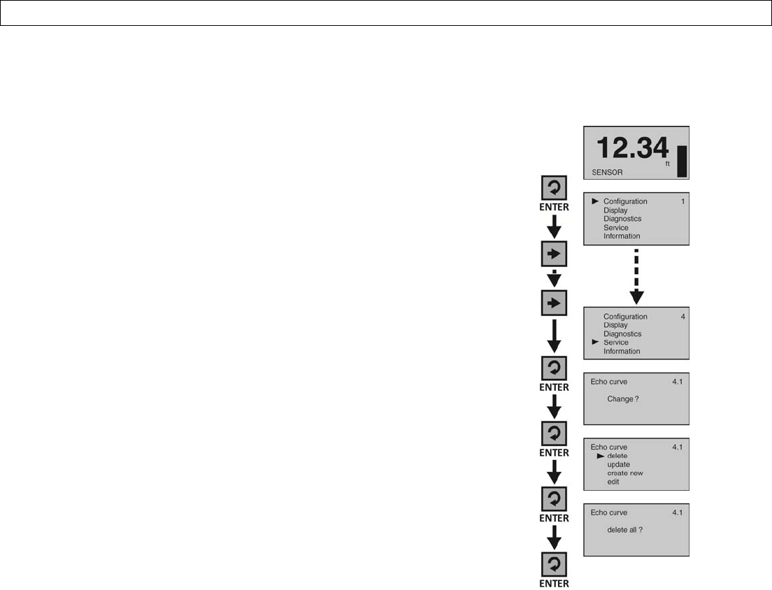
Rev9_4MN301700Page57of72
TROUBLESHOOTINGSectionEight
FalseEchoCurveDelete
ThisfunctiondeletesasavedFalseEchoCurve.Note:Ifyouaredissatisfiedwiththesensor’sperformance(operating
withaFalseEchoCurve),youmaydeleteit,andconsidercreatinganewFalseEchoCurve.
1. FromtheMainScreen,pressEntertoadvanceintotheMain
Menu.
2. PressRightArrowrepeatedlyuntilthearrowisnextto
Service.
3. PressEntertoadvanceintoServiceandEchoCurvewill
appear.
4. PressEntertomakeachangetoEchoCurve.
5. PressEntertoselectDelete.
6. PressEntertoDeleteAll.
7. PressESCtoreturntoServiceandpressESCasecondtimeto
returntotheMainScreen.
UNRELEASED
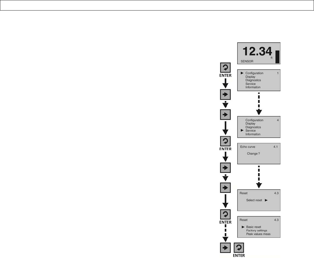
Page58of72MN301700Rev9_4
TROUBLESHOOTINGSectionEight
Reset
Thisfunctionresetsthesensor’sconfiguration(basicorfactory)settingsandmemory(peakvaluesmeasured).
1. FromtheMainScreen,pressEntertoadvanceintotheMain
Menu.
2. PressRightArrowrepeatedlyuntilthearrowisnextto
Service.
3. PressEntertoadvanceintoService.
4. PressRightArrowrepeatedlyuntilResetappears.
5. PressEntertoadvanceintoReset.
6. UsetheRightArrowtoscrollamongthethreeresettypes
(BasicReset,FactorySettings,PeakValueMeas).
1. BasicReset
a. Resetsbasicconfigurationsettings,process
adjustmentsettings,andpeaklevelvaluesin
memory(retaininganyadvancedadjustment
settings).
2. FactorySettings
a. ResetsALLsettingsandmemorytofactory
default.
3. PeakValuesMeasured
a. Resetstheminimumandmaximumpeak
levelvaluesinmemory(retaininganybasic
configuration,processadjustmentand
advancedadjustmentsettings).
7. UseEntertoselectthedesiredtypeofreset.
8. Whendone,pressESCtoreturntoService,andpressESCa
secondtimetotheMainScreen.
UNRELEASED
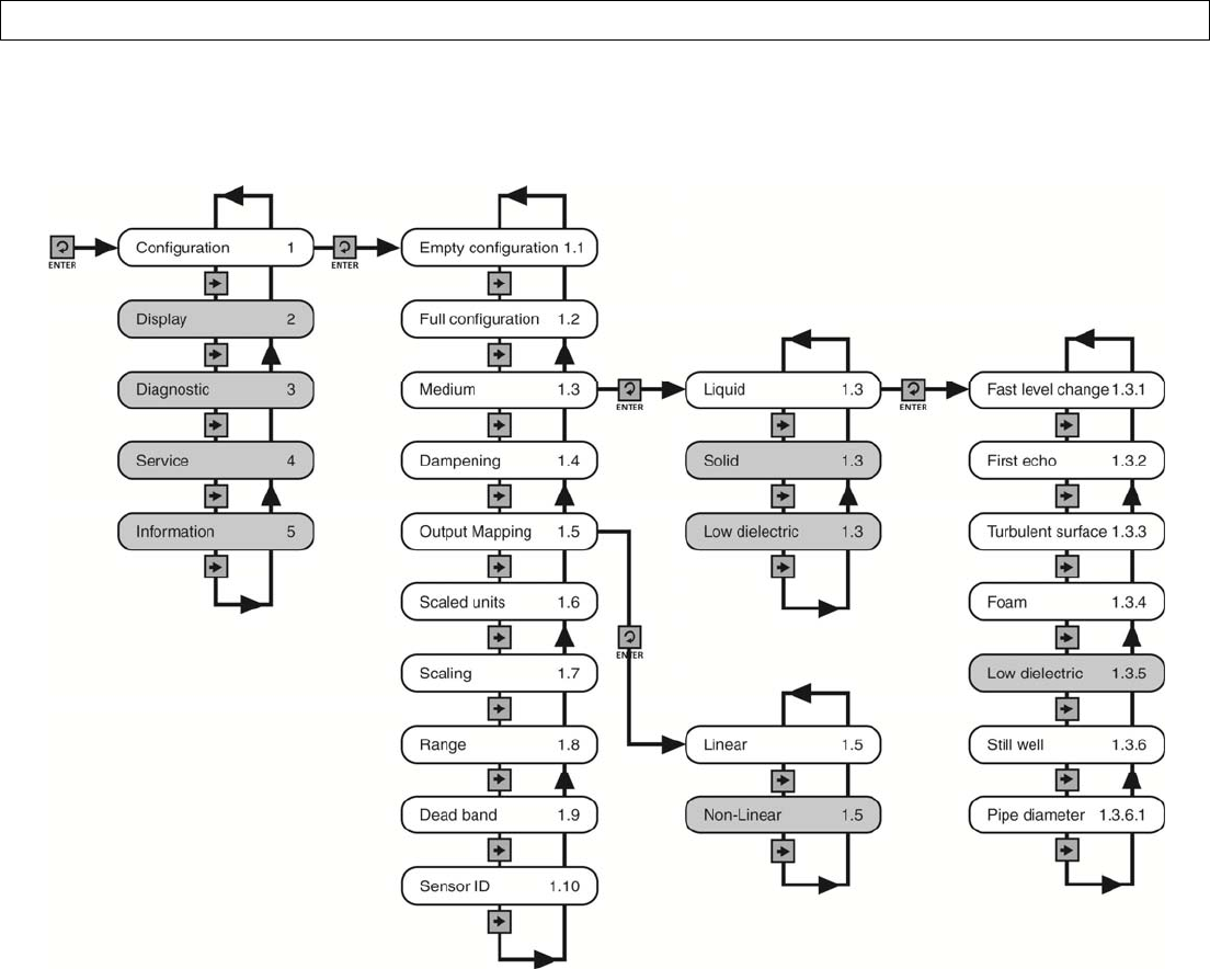
Rev9_4MN301700Page59of72
APPENDIXSectionNine
ConfigurationMenu
ThebasicconfigurationfunctionsarefoundunderConfiguration.Thebelowtreeshowsthe10functionsettingsand
howtonavigatebetweenthem.
Note:PressESCAPEtoback‐uptothepreviouslevel.
UNRELEASED
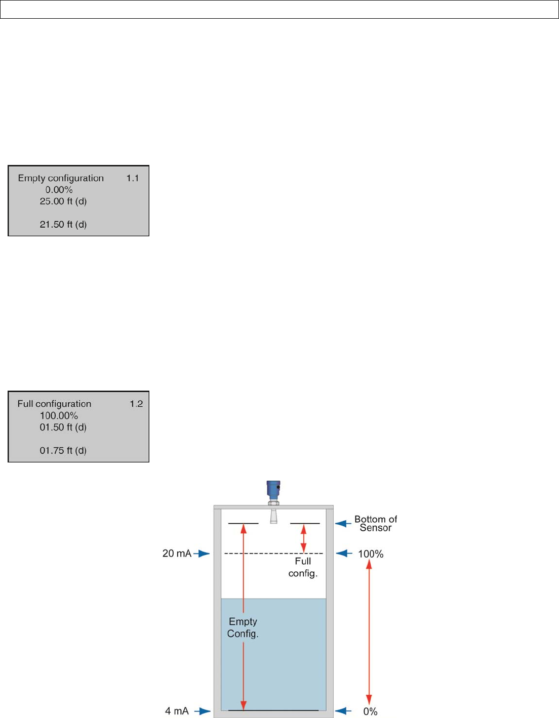
Page60of72MN301700Rev9_4
APPENDIXSectionNine
EmptyConfiguration
Thisfunctionadjuststheemptylinearscaledcurrentoutput(4mA)andprovidestwodifferentadjustmentmethods:
Theprimarymethodinvolvessettingthevaluebaseduponthedistancefromthebottomofthesensor.Thisisa
measuredvalueusingtheunitsofoperationforthesensor.Forexample,iftheunitsofoperationareinmeters,
thenthesettingmustalsobeinmeters.
AsecondmethodinvolvessettingavaluebaseduponthepercentageoftheRangevalue.Forexample,ifthe
Rangeissetto10ft,thena10%settingisequivalentto1ftofliquidheightor9ftofairgapawayfromthe
sensor.Note:SettheRangevaluebeforesettingtheEmptyConfigurationvalue.
ShowsthepercentageofemptybasedupontheRangesetting.
Showsthedistancefromthebottomofthesensortotheemptytank.
Showstheairgapdistancefromtheliquidtothebottomofthesensor.
FullConfiguration
Thisfunctionadjuststhefulllinearscaledcurrentoutput(20mA)andprovidestwodifferentadjustmentmethods:
Theprimarymethodinvolvessettingthevaluebaseduponthedistancefromthebottomofthesensor.Thisisa
measuredvalueusingtheunitsofoperationforthesensor.Forexample,iftheunitsofoperationareinmeters,
thenthesettingmustalsobeinmeters.
ThesecondmethodinvolvessettingavaluebaseduponthepercentageoftheRangevalue.Forexample,ifthe
Rangeissetto10ft,thena95%settingisequivalentto9.5ftofliquidheightor0.5ftorairgapawayfromthe
sensor.Note:SettheRangevaluebeforesettingtheFullconfigurationvalue.
ShowsthepercentageoffullbasedupontheRangesetting.
Showsthedistancefromthebottomofthesensortothefulltank.
Showstheairgapdistancefromtheliquidtothebottomofthesensor.
UNRELEASED
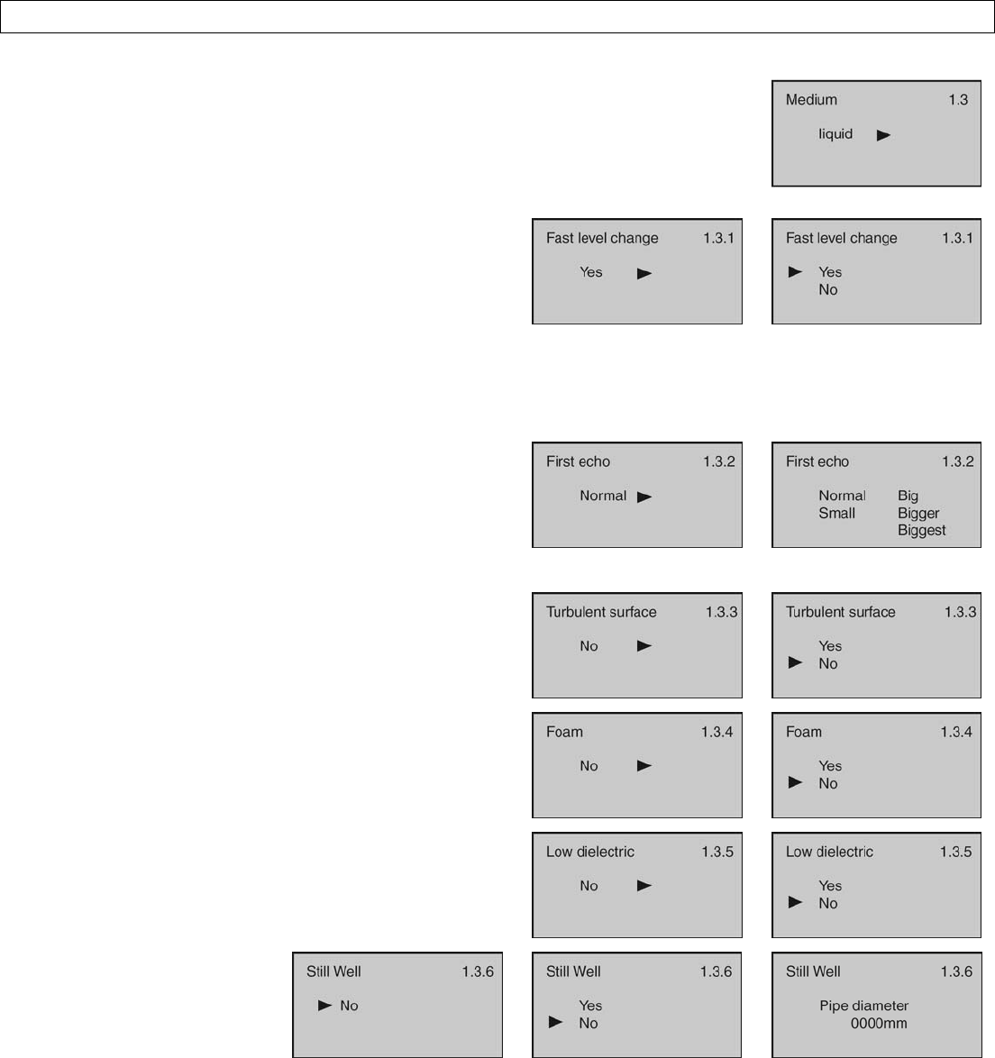
Rev9_4MN301700Page61of72
APPENDIXSectionNine
Medium
ThisfunctionidentifiesthetypeofmediathatthesensorismeasuringincludingLiquid,
SolidorLowDielectric.Eachhasvarioussettingstoaddressthedifferentreflective
propertiesassociatedwitheachmedium.DefaultisLiquid.
TheLiquidMediumfunctionhasthefollowingsettings:
FastLevelChange‐Usedwhenthemedia’slevelriseor
fallwithinthetankisgreaterthanarateof1”persecond
(25.4mm/sec).SelectionsareYESorNO.DefaultisNO.
FirstEcho‐Usedwhenthesensorhasdifficultyseeing
thefirstechoreturn.Thissettingadjuststhepeak
strength(dB)ofthefirstecho.DefaultisNormal.Below
arethesettings:
o Normal‐Noadjustment
o Small‐Decreasesby10dB
o Big‐Increasesby10dB
o Bigger‐Increasesby20dB
o Biggest‐Increasesby40dB
TurbulentSurface‐Usedwhenthesurfaceoftheliquid
isturbulentoragitated.SelectionsareYESorNO.
DefaultisNO.
Foam‐Usedwhentheentireliquidsurfaceiscovered
withfoam.SelectionsareYESorNO.DefaultisNO.
LowDielectric‐Usedwhentheliquidhasalowdielectric
constant(andshouldnotbeperformedwithoutfirst
consultingwiththefactory).SelectionsareYESorNO.
DefaultisNO.
StillWell‐Usedwhenthe
sensorisinstalledinastill
well,standpipeorsight
glass.SelectionsareYESor
NO.DefaultisNO.Note:If
YESisselected,thepipe
(inner)diametermustbe
entered.
UNRELEASED
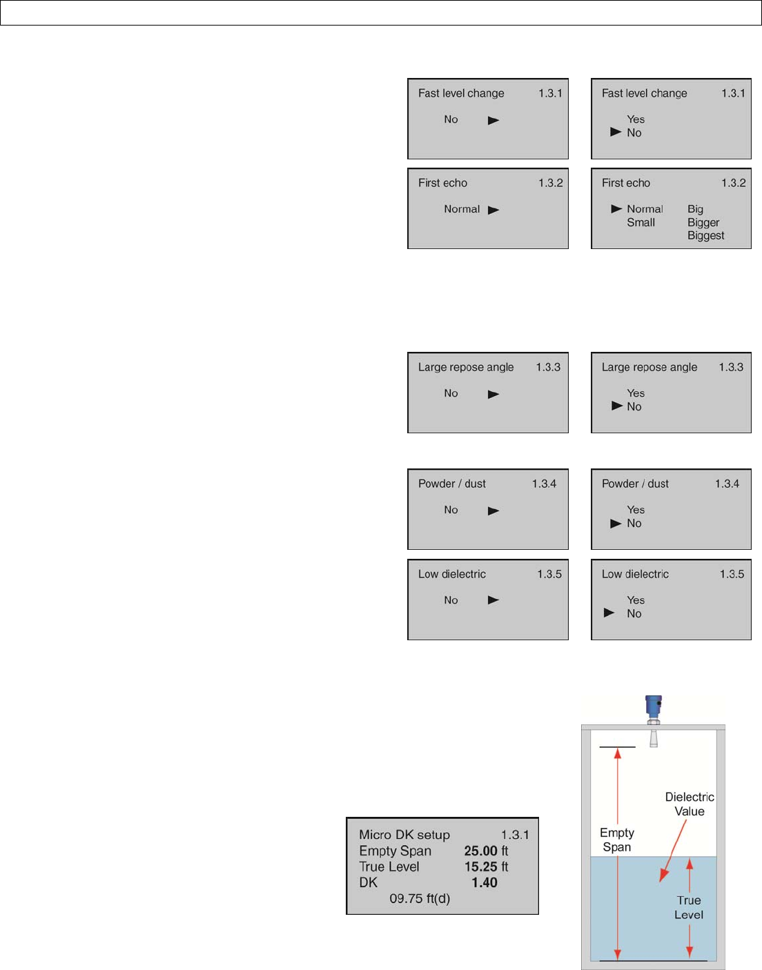
Page62of72MN301700Rev9_4
APPENDIXSectionNine
TheSolidMediumfunctionhasthefollowingsettings(andshouldnotbeperformedwithoutfirstconsultingwiththe
factory):
FastLevelChange‐Usedwhenthemedia’slevelriseor
fallwithinthetankisgreaterthanarateof1”persecond
(25.4mm/sec).SelectionsareYESorNO.DefaultisNO.
FirstEcho‐Usedwhenthesensorhasdifficultyseeing
thefirstechoreturn.Thissettingadjuststhepeak
strength(dB)ofthefirstecho.DefaultisNormal.Below
arethesettings:
o Normal‐Noadjustment
o Small‐Decreasesby10dB
o Big‐Increasesby10dB
o Bigger‐Increasesby20dB
o Biggest‐Increasesby40dB
LargeReposeAngle‐Usedwhenthereposeangleofthe
materialissteep.Reposeangleisthesteepestangleof
assentordescentrelativetothehorizontalplanethata
materialcanbepiledwithoutsliding.Thereposeangle
variesbetweendifferentmaterials.SelectionsareYesor
No.DefaultisNo.
Powder/Dust‐Usedwhenpowderordustarepresent
intheatmosphereabovethematerial.Selectionsare
YesorNo.DefaultisNo.
LowDielectric‐Usedwhenthematerialhasalow
dielectricconstant(andshouldnotbeperformedwithout
firstconsultingwiththefactory).SelectionsareYESor
NO.DefaultisNO.
TheLowDielectricMediumfunctionhasthefollowingsettings(andshouldnotbeperformedwithoutfirstconsulting
withthefactory):
Whenthedielectricconstantofthemediais≤4,theamplitudeofthedirectecho
fromthemediamaybelowanddifficulttodetect.However,bymeasuringtheecho
reflectedfromthebottomofthetank,theliquidlevelcanbemeasured.Two
parametersmustbeinputtocompletethesetup:1)Distancefromthebottomofthe
sensortothetankbottom(EmptySpan)and;2)Distancefromthetankbottomto
theliquidlevel(TrueLevel).
EmptySpan‐Distancefromthebottomofthe
sensortothetankbottom.
TrueLevel‐Distancefromthetankbottomto
theliquidlevel..
DK‐Mediadielectricconstant(determinedby
sensor).
Note:Oncethisfeaturehasbeenactivated,onlyafactorysettingcanundoits
activation.AfactoryresetwilleraseallactivesettingsincludingEchoCurves.
UNRELEASED
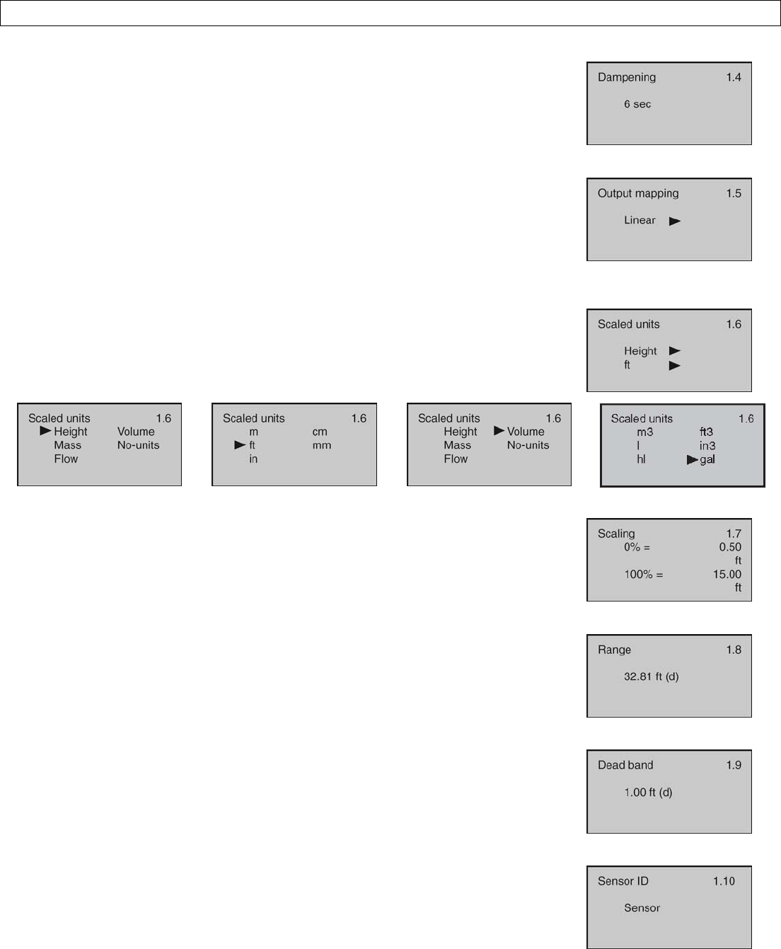
Rev9_4MN301700Page63of72
APPENDIXSectionNine
Dampen
Thisfunctionsetsthesamplingrateforwhichthesensorupdatesthecurrentoutput.
Thevalueisenteredinseconds.Defaultis6seconds.
Decreasingthevaluewillmaketheoutputmoreresponsivetolevelchanges.
Increasingthevaluewillmaketheoutputlessresponsivetolevelchanges.
OutputMapping
Thisfunctionsetsthecorrelationbetweenthemeasuredvalueandthecurrent
output.SelectionsareLinearorNon‐Linear.DefaultisLinear.
KeepthesettingonLinear.Note:Thissettingshouldnotbechangedwithout
firstconsultingwiththefactory.
ScaledUnits
Thisfunctionsetsthetypeofmeasurement(Height,Volume,Mass,FloworNo‐
Units)andunitsofmeasurement(whichvarybaseduponthetypeofmeasurement)
displayedandinputduringconfiguration.DefaultisHeightinUnitsoffeet(ft).
Scaling
Thisfunctionsetsthespanvaluesfor0%and100%asanalternativemethodof
adjustingtheEmptyConfigurationandFullConfigurationsettings.Defaultsare0%
and100%.
Range
Thisfunctionsetsthemaximumrangethatthesensorcanmeasurewhichistypically
thedistancefromthebottomofthesensortotheemptytankbottom.Defaultisthe
maximumrangeofthesensor.
DeadBand
Thisfunctionsetsthedeadbandortheminimumdistancethatthesensorwill
measure.Defaultis12”(30cm).Minimumsettingis2”fromthebottomofthe
antenna.Consultfactorywhensettingthedeadbandlessthanthefactorysetting.
SensorID
Thisfunctionsetsan11‐digitidentificationcode.Thesettingcanusealphanumeric
valuesfromAtoZand0to9.Defaultisthesensor’s4‐digitSeriesnumber.
UNRELEASED
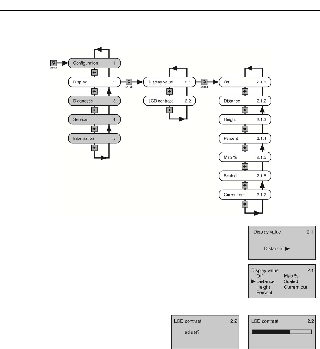
Page64of72MN301700Rev9_4
APPENDIXSectionNine
DisplayMenu
ThismenusetstheDisplayValueandLCDContrast.Thebelowtreeshowsthe2functionsettingsandhowtonavigate
betweenthem.
DisplayValue
ThisfunctionsetstheDisplayValue.Defaultis(airgap)Distance.Belowarethesettings:
OFF‐TurnsthedisplayOFF.
Distance‐Displaysthedistancefromthebottomofthesensortotheliquidsurface.
Height‐DisplaystheheightofmediainthetankfromtheMaximumRangeSetting.
PercentSpan‐Displaysthelevelbasedonitspercentageofoperationalspan.
MapPercentage‐Displaysthelevelbasedonitspercentageofoperationalrange.
Scaled‐Displaysthelevelbasedonascaledvaluebetween0(empty)and10(full).
CurrentOutput‐Displaysthe4‐20mAcurrentoutput.
LCDContrast
ThisfunctionsetstheB/Wdisplaycontrast.PresstheUp
Arrowtoincreasethecontrast,andpresstheRightArrowto
decreasethecontrast.
UNRELEASED
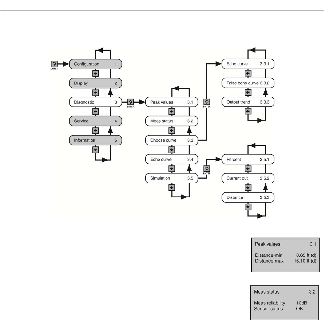
Rev9_4MN301700Page65of72
APPENDIXSectionNine
DiagnosticsMenu
Thismenuprovidesinformationabouttheoperationalstatusofthesensoranddiagnostictools.Thebelowtreeshows
the5functionsettingsandhowtonavigatebetweenthem.
PeakValues
Thisfunctiondisplaysthelowestandhighestlevelheightdistances(d)thatthesensorhas
measuredduringoperation.Toresetthesevalues,usetheReset>>PeakMeasuredValues
optionfoundundertheServiceMenu.
MeasurementStatus
Thisfunctiondisplaysthesignalstrength(dB)oftheechoreturns(Measurement
Reliability)andtheoperationalstatusofthesensor(SensorStatus).Asignalstrengthof
10dBorhigherisacceptable.Anythingunder10dBisconsideredaweaksignal.Thecause
ofaweaksignalisoftenobstructionswithinthebeampathorapoorinstallation.
Sensorstatusconfirmswhetherthesensorisoperatingasexpected.Ifnormal,the
descriptorwillbeOK.Ifabnormal,thedescriptorwillbeoneofthefollowingerrorcodes:
E11–InsufficientpowerE12–SensoropencircuitE14–WeakreturnechoE15–ROMerrorE17–ROMerror
UNRELEASED
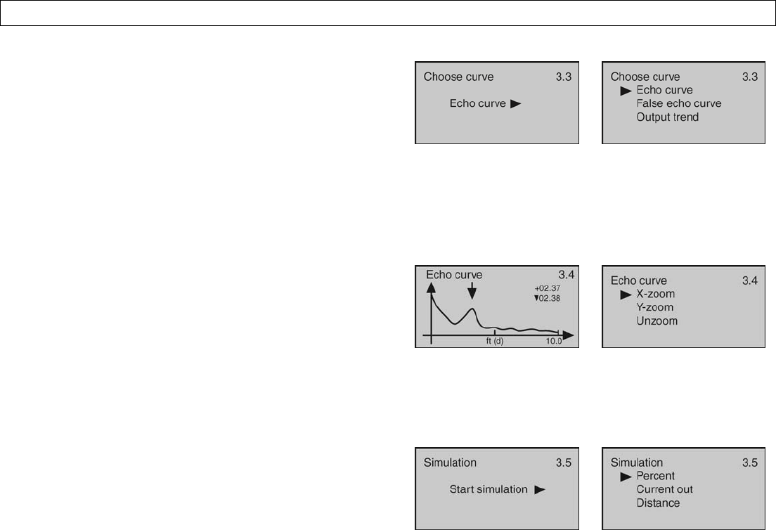
Page66of72MN301700Rev9_4
APPENDIXSectionNine
ChooseCurve
Thisfunctionsetswhichinformationisdisplayed.Defaultis
EchoCurve.
EchoCurve‐Showstheechoreturnenergyreceivedbythe
sensoroverdistance.
FalseEchoCurve‐Showsthefalseechoreturnswhichare
mappedout(notconsidered)bythesensor.
OutputTrend‐Showsrecenthistoryofwherethepast
levelreadingshaveoccurred.
EchoCurve
ThisfunctionshowstheEchoCurveandallowstheuserto
zoominandmagnifyinformationalongtheX‐axisandY‐axis.
X‐zoom‐ExpandsechoinformationalongtheX‐axis.Used
todeterminethelocationofanecho.
Y‐zoom‐Expandsechoinformationalongthey‐axis.Used
todeterminetheenergyofanecho.
Unzoom‐Returnsthedisplaytotheoriginalsetting.
Simulation
Thisfunctionsetsafixed4‐20mAcurrentoutputfromthe
sensorforpurposesoftestingdevicesreceivinginformation
fromthesensor.Thesimulatedcurrentoutputmaybeset
withthebelowthreeinputmethods:
Percent‐Thismethodusespercentageofspan(0‐100%)to
setthecurrentoutput(4‐20mA)betweentheEmptyand
FullConfigurationvalueswith100%equalto20mAand
0%equalto4mA.
CurrentOut‐Thismethoddirectlysetsthecurrentoutput
(4‐20mA)tothedesiredvalue.
Distance‐Thismethodusesdistancefromthesensor’s
measurementlocationtosetthecurrentoutput(4‐20mA)
betweentheEmptyandFullConfigurationvalues.
UNRELEASED
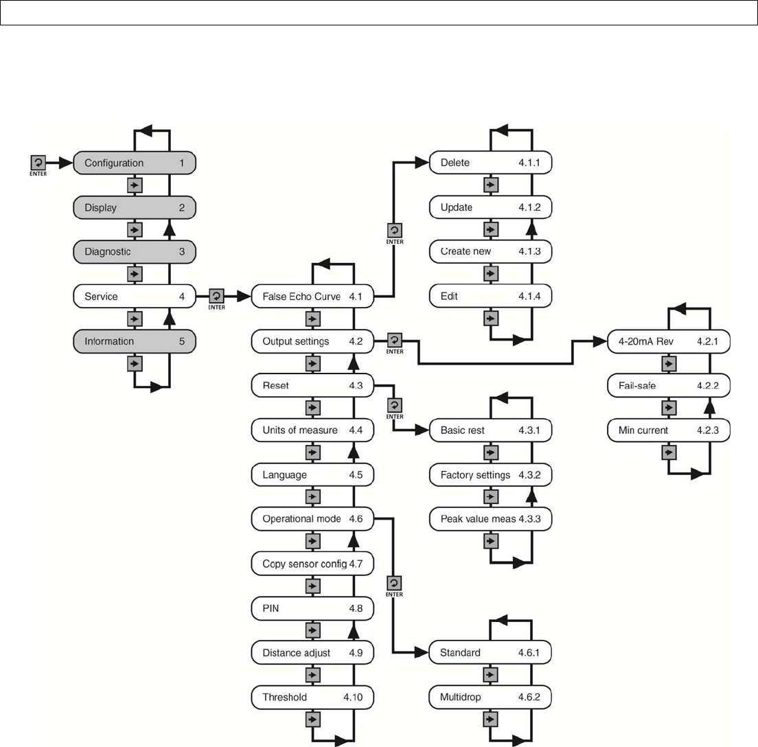
Rev9_4MN301700Page67of72
APPENDIXSectionNine
ServiceMenu
Thismenuisusedtomakemoreadvancedadjustmentstothesensor.Note:Someofthesefunctionsshouldonlybe
performedbyatrainedtechnician.
UNRELEASED
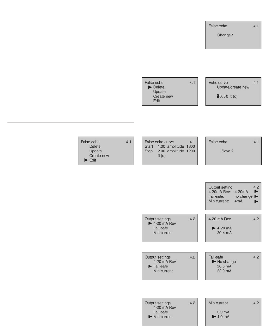
Page68of72MN301700Rev9_4
APPENDIXSectionNine
FalseEcho
Obstructionsinthetank(mixerblades,sidewallweldjointsormaterialbuild‐up,
submersiblepumps,piping,otherapparatus)ortalltankrisersorinstallationfittingscan
createfalseechoreturnsthatimpairthesensor’smeasurement.Thisfunctionmapsall
echoreturnswithinthetank,differentiatingbetweengoodandfalseechoes,andstores
thoseidentifiedasfalseintotheFalseEchoCurve,sotheywillnotbeconsideredinthe
levelmeasurement.Note:AFalseEchoCurveshouldonlybeperformedwhenthetankis
emptysothatallfalsereflectionswillbedetected.
ThisfunctionallowstheselectionofthebelowFalseEcho
Curvesettings:
Delete‐UsedtoremoveastoredFalseEchoCurve.
Update‐UsedtoupdateastoredFalseEchoCurve.Note:
DonotusethisfunctiontoupdateanexistingFalseEcho
CurvewhenthelevelisabovetheoriginalFalseEchoCurve.
CreateNew‐UsedtocreateanewFalseEchoCurve.
Edit‐Usedtoeditthefalse
echoesstoredinaFalseEcho
Curve.Note:Thisfunction
shouldonlybeperformedby
atrainedtechnician.
OutputSettings
Thisfunctionallowstheselectionofthebelowof4‐20mAReverse,Fail‐SafeandMinimum
Currentoutputsettings.Theinitialscreenindicatesthestatusofthethreefunctions.
4‐20mAReverse‐Usedtosetthecurrentoutputat4‐20
mAor20‐4mA.Selecting4‐20mAsetstheoutputwith
4mA@bottomand20mA@topofthetank.Selecting20‐
4mAsetstheoutputwith20mA@bottomand4mA@
topofthetank.Defaultis4‐20mA.
Fail‐Safe–Usedtosetthecurrentoutputtoadesignatedif
thesensorlosesmeasurementconfidence.SelectingNo
Changewillholdthecurrentatitslastvalidcurrentoutput.
Selecting20.5mAwillforcethecurrenttojumpto20.5mA.
Selecting22.5mAwillforcethecurrenttojumpto22.5
mA.Defaultis22.0mA.
MinimumCurrent‐Usedtosettheminimumcurrent
outputateither4.0mAor3.9mADefaultis4.0mA.
UNRELEASED
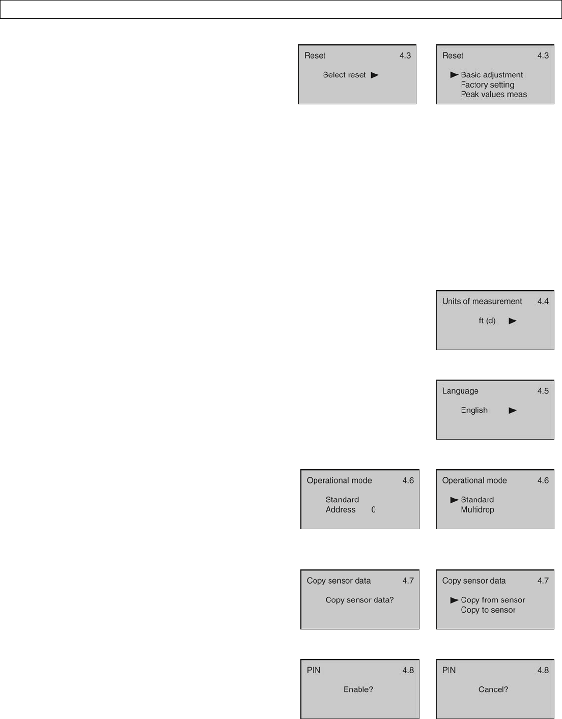
Rev9_4MN301700Page69of72
APPENDIXSectionNine
Reset
Thisfunctionallowstheconfiguration(basicorfactory)
settingsandmemory(peakvaluesmeasured)tobereset.
Belowarethethreeresettypes:
BasicReset–Usedtoresetthebasicconfiguration
settings,processadjustmentsettings,andpeaklevel
valuesinmemory(retaininganyadvancedadjustment
settings).
FactorySettings–UsedtoresetALLsettingsandmemory
tofactorydefault.
PeakValuesMeasured–Usedtoresettheminimumand
maximumpeaklevelvaluesinmemory(retaininganybasic
configuration,processadjustmentandadvanced
adjustmentsettings).
UnitsofMeasurement
ThisfunctionallowstheunitsofmeasurementtobechangedbetweenMetricandEnglish
systemunits.
Language
Thisfunctionsetsthedisplaylanguage.DefaultisEnglish.
OperationalMode
Thisfunctionallowsthesensordigitaladdresstobechanged
fromtheStandardmodewithanaddressof0toaMultidrop
modewheretheaddresscanbesetfrom1to15.Defaultis
Address0.Note:Thisfunctionshouldonlybeperformedby
atrainedtechnician.
CopySensorData
Thisfunctionallowsconfigurationandmemorydatatobe
uploadedtoordownloadedfromthesensor.Note:This
functionshouldonlybeperformedbyatrainedtechnician.
PIN
Thisfunctionallowsthesensorconfigurationtobelockedvia
apresetPIN.Note:Thisfunctionshouldonlybeperformedby
atrainedtechnician.
UNRELEASED
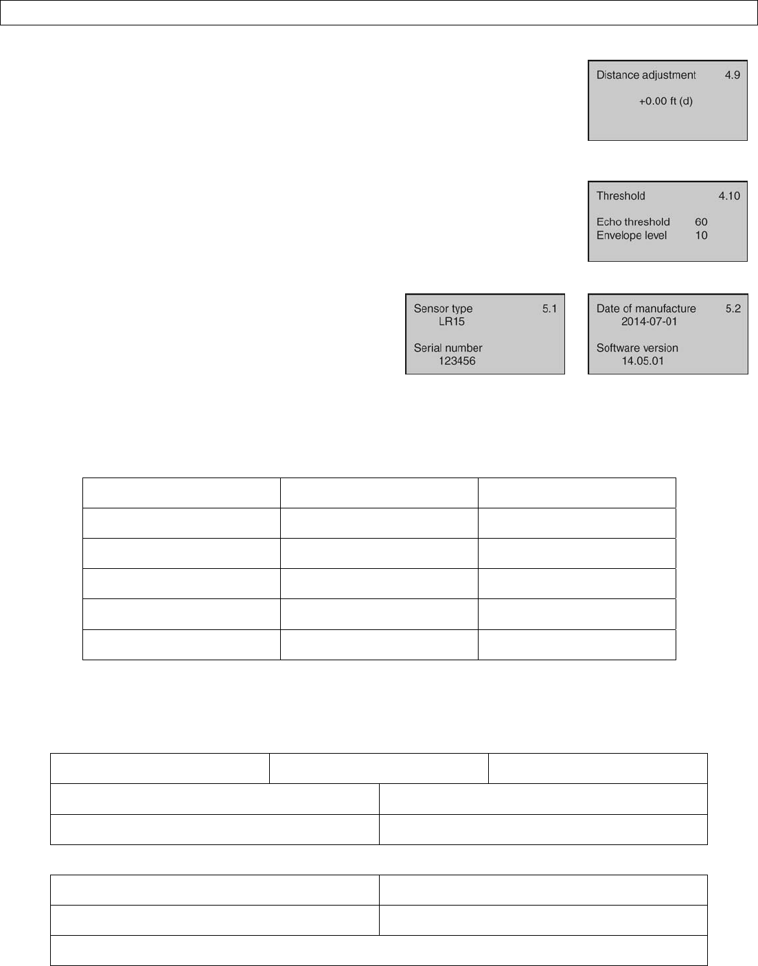
Page70of72MN301700Rev9_4
APPENDIXSectionNine
DistanceAdjustment
Thisfunctionallowsthefactorysetdistanceofameasuredvaluetobeadjusted.Note:
Thisfunctionshouldonlybeperformedbyatrainedtechnician.
Threshold
Thisfunctionallowsthefactorysetechothresholdtobeadjusted.Note:Thisfunction
shouldonlybeperformedbyatrainedtechnician.
Information
Thisfunctiondisplaysbasicinformationaboutyoursensor
includingsensortype,serialnumber,dateofmanufacture
andsoftwareversion.
FactorySettings
BelowaretheEmptyConfigurationandFullConfigurationfactorysettingsforeachsensor.
Series EmptyConfiguration(4mA)FullConfiguration(20mA)
LR10 32.81’(10m)1.64’(0.5m)
LR15 98.42’(30m)1.64’(0.5m)
LR20 65.61’(20m)1.64’(0.5m)
LR25 114.83’(35m)1.64’(0.5m)
LR30 94.82’(30m)1.64’(0.5m)
UserConfiguration
Filloutthebelowchartandkeeparecordofyoursensorconfiguration.
Configuration
UnitsofMeasurement:FeetMeters
EmptyConfiguration: FullConfiguration:
Range(Maximum):DeadBand:
ProcessAdjustments
FastLevelChange:NoYesAgitatedSurface:NoYes
Foam:NoYesLowDielectric:NoYes
StillWell:NoYesDiameter:
UNRELEASED

Rev9_4MN301700Page71of72
APPENDIXSectionNine
Notes
Subject Comment
UNRELEASED

Page72of72MN301700Rev9_4
APPENDIXSectionNine
Warranty
Flowlinewarrantstotheoriginalpurchaserofitsproductsthatsuchproductswillbefreefromdefectsinmaterialand
workmanshipundernormaluseandserviceinaccordancewithinstructionsfurnishedbyFlowlineforaperiodoftwo
yearsfromthedateofmanufactureofsuchproducts.Flowline'sobligationunderthiswarrantyissolelyandexclusively
limitedtotherepairorreplacement,atFlowline'soption,oftheproductsorcomponents,whichFlowline'sexamination
determinestoitssatisfactiontobedefectiveinmaterialorworkmanshipwithinthewarrantyperiod.Flowlinemustbe
notifiedpursuanttotheinstructionsbelowofanyclaimunderthiswarrantywithinthirty(30)daysofanyclaimedlackof
conformityoftheproduct.Anyproductrepairedunderthiswarrantywillbewarrantedonlyfortheremainderofthe
originalwarrantyperiod.Anyproductprovidedasareplacementunderthiswarrantywillbewarrantedforthefulltwo
yearsfromthedateofmanufacture.
Returns
ProductscannotbereturnedtoFlowlinewithoutFlowline'spriorauthorization.Toreturnaproductthatisthoughttobe
defective,gotowww.flowline.com,andsubmitacustomerreturn(MRA)requestformandfollowtheinstructions
therein.Allwarrantyandnon‐warrantyproductreturnstoFlowlinemustbeshippedprepaidandinsured.Flowlinewill
notberesponsibleforanyproductslostordamagedinshipment.
Limitations
Thiswarrantydoesnotapplytoproductswhich:1)arebeyondthewarrantyperiodorareproductsforwhichthe
originalpurchaserdoesnotfollowthewarrantyproceduresoutlinedabove;2)havebeensubjectedtoelectrical,
mechanicalorchemicaldamageduetoimproper,accidentalornegligentuse;3)havebeenmodifiedoraltered;4)
anyoneotherthanservicepersonnelauthorizedbyFlowlinehaveattemptedtorepair;5)havebeeninvolvedin
accidentsornaturaldisasters;or6)aredamagedduringreturnshipmenttoFlowline.Flowlinereservestherightto
unilaterallywaivethiswarrantyanddisposeofanyproductreturnedtoFlowlinewhere:1)thereisevidenceofa
potentiallyhazardousmaterialpresentwiththeproduct;or2)theproducthasremainedunclaimedatFlowlineformore
than30daysafterFlowlinehasdutifullyrequesteddisposition.Thiswarrantycontainsthesoleexpresswarrantymade
byFlowlineinconnectionwithitsproducts.ALLIMPLIEDWARRANTIES,INCLUDINGWITHOUTLIMITATION,THE
WARRANTIESOFMERCHANTABILITYANDFITNESSFORAPARTICULARPURPOSE,AREEXPRESSLYDISCLAIMED.The
remediesofrepairorreplacementasstatedabovearetheexclusiveremediesforthebreachofthiswarranty.INNO
EVENTSHALLFLOWLINEBELIABLEFORANYINCIDENTALORCONSEQUENTIALDAMAGESOFANYKINDINCLUDING
PERSONALORREALPROPERTYORFORINJURYTOANYPERSON.THISWARRANTYCONSTITUTESTHEFINAL,COMPLETE
ANDEXCLUSIVESTATEMENTOFWARRANTYTERMSANDNOPERSONISAUTHORIZEDTOMAKEANYOTHER
WARRANTIESORREPRESENTATIONSONBEHALFOFFLOWLINE.Thiswarrantywillbeinterpretedpursuanttothelawsof
theStateofCalifornia.Ifanyportionofthiswarrantyisheldtobeinvalidorunenforceableforanyreason,suchfinding
willnotinvalidateanyotherprovisionofthiswarranty.
Forcompleteproductdocumentation,videotraining,andtechnicalsupport,gotowww.flowline.com.
Forphonesupport,call562‐598‐3015from8amto5pmPST,Mon‐Fri.
(PleasemakesureyouhavethePartandSerialnumberavailable.)
UNRELEASED