Fluke Electronics 805FC Vibration Meter User Manual
Fluke Electronics Vibration Meter
UserManual.wiki
>
Fluke Electronics
>
805FC User Manual
>
User Manual
Contents
1.
User Manual
2.
RF Exposure Warning Statement
3.
Antenna Information
User Manual
Navigation menu
Upload a User Manual
Namespaces
Wiki Guide
HTML
PDF
Info
Views
User Manual
Discussion / Help
Navigation


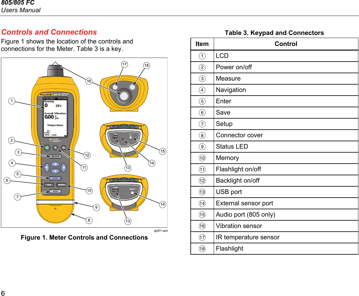
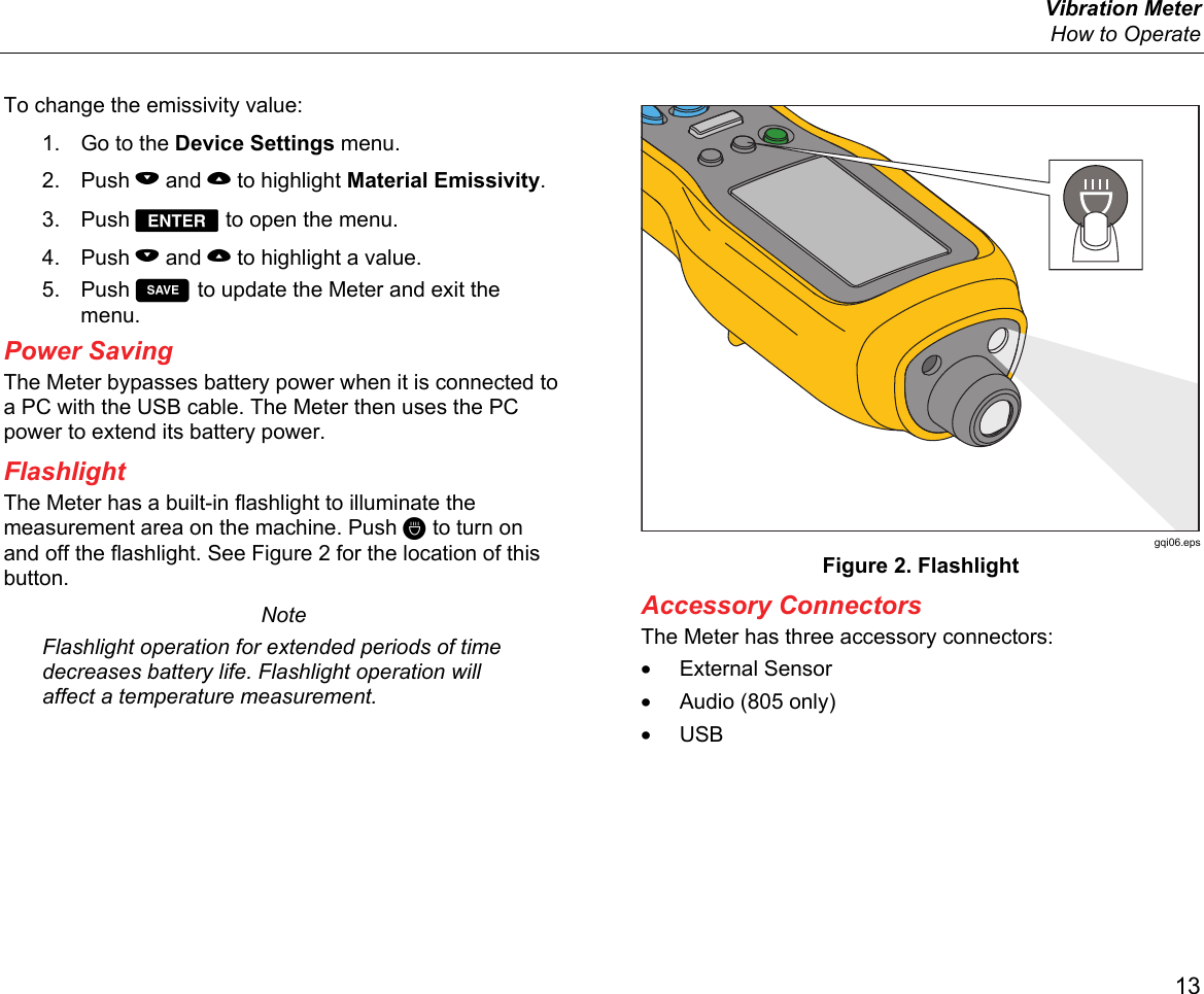
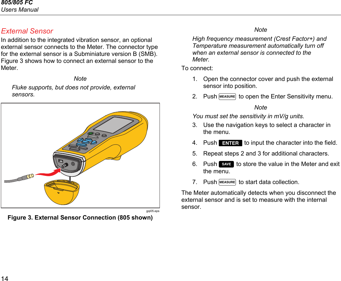
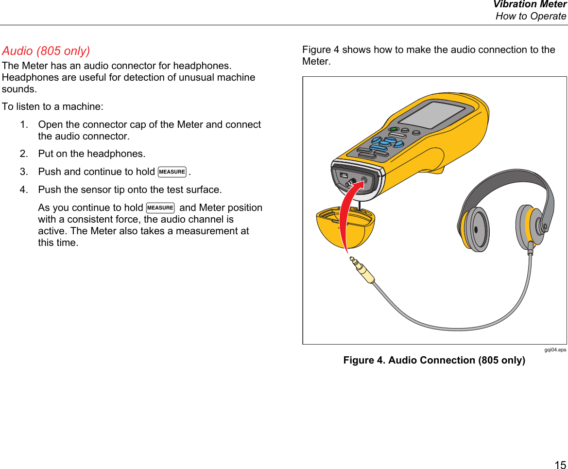
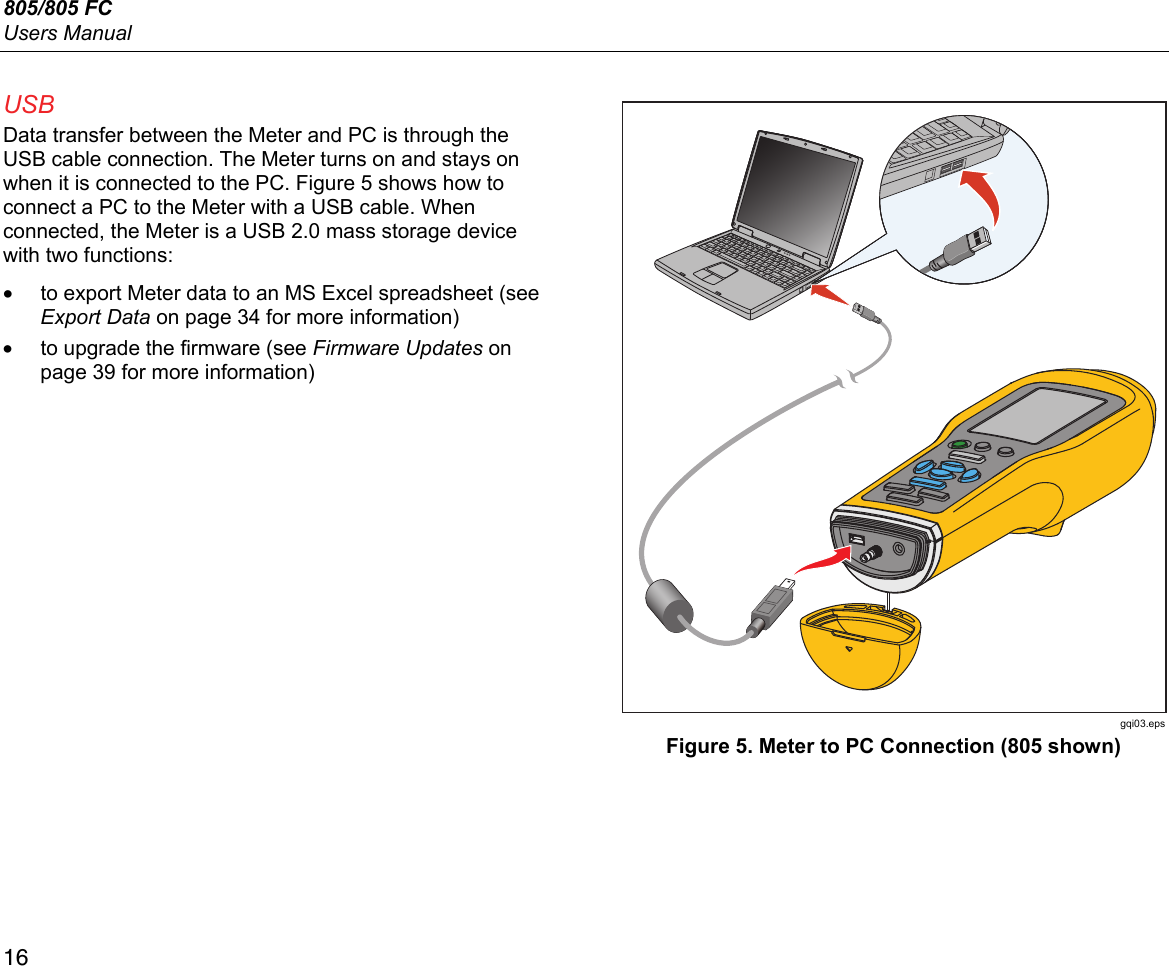
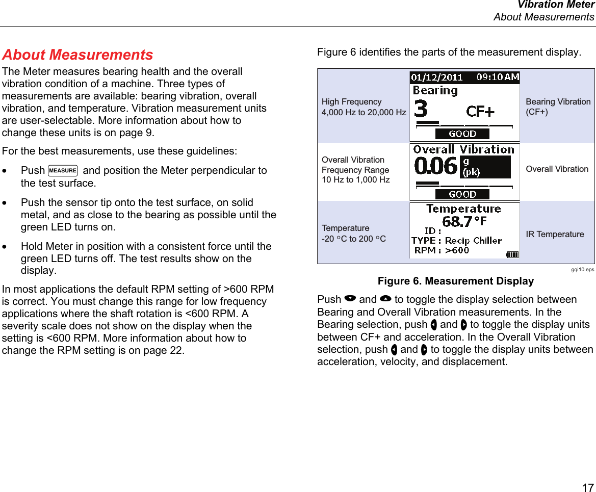
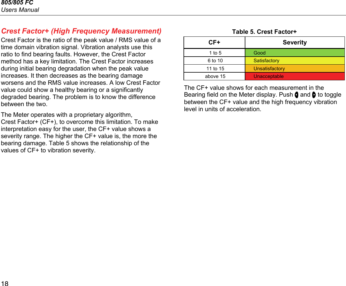
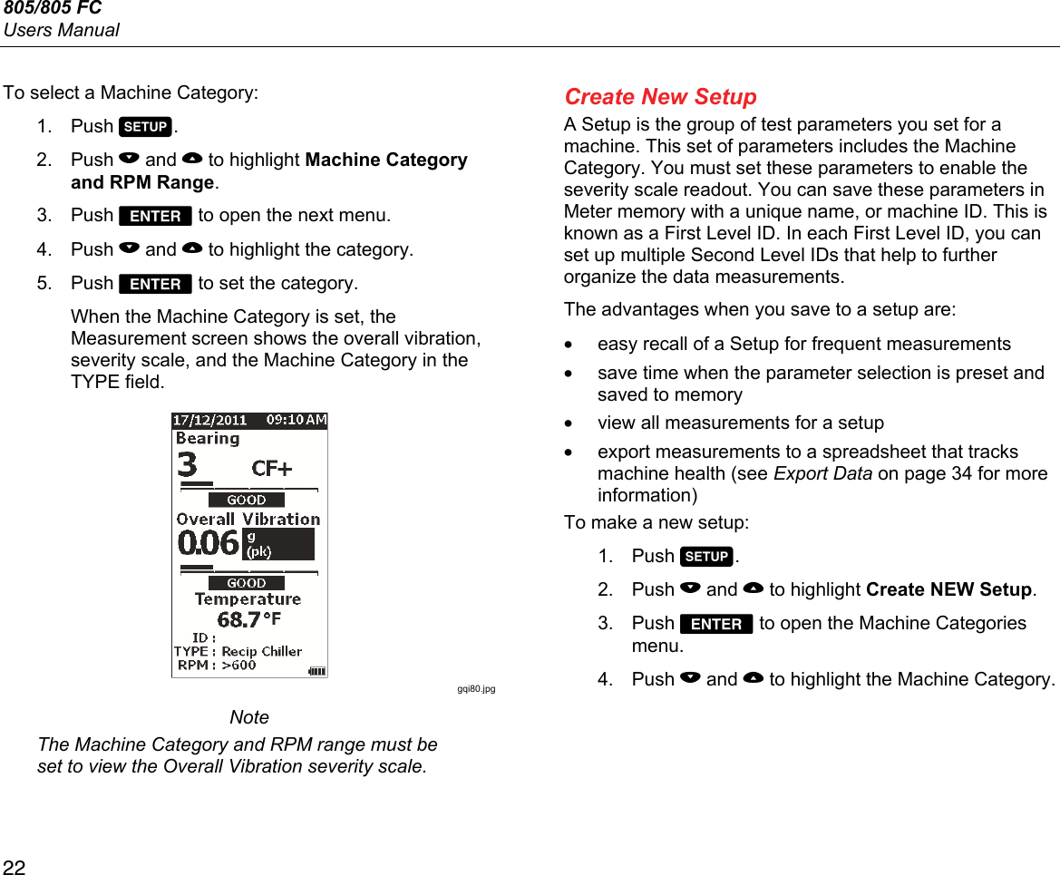
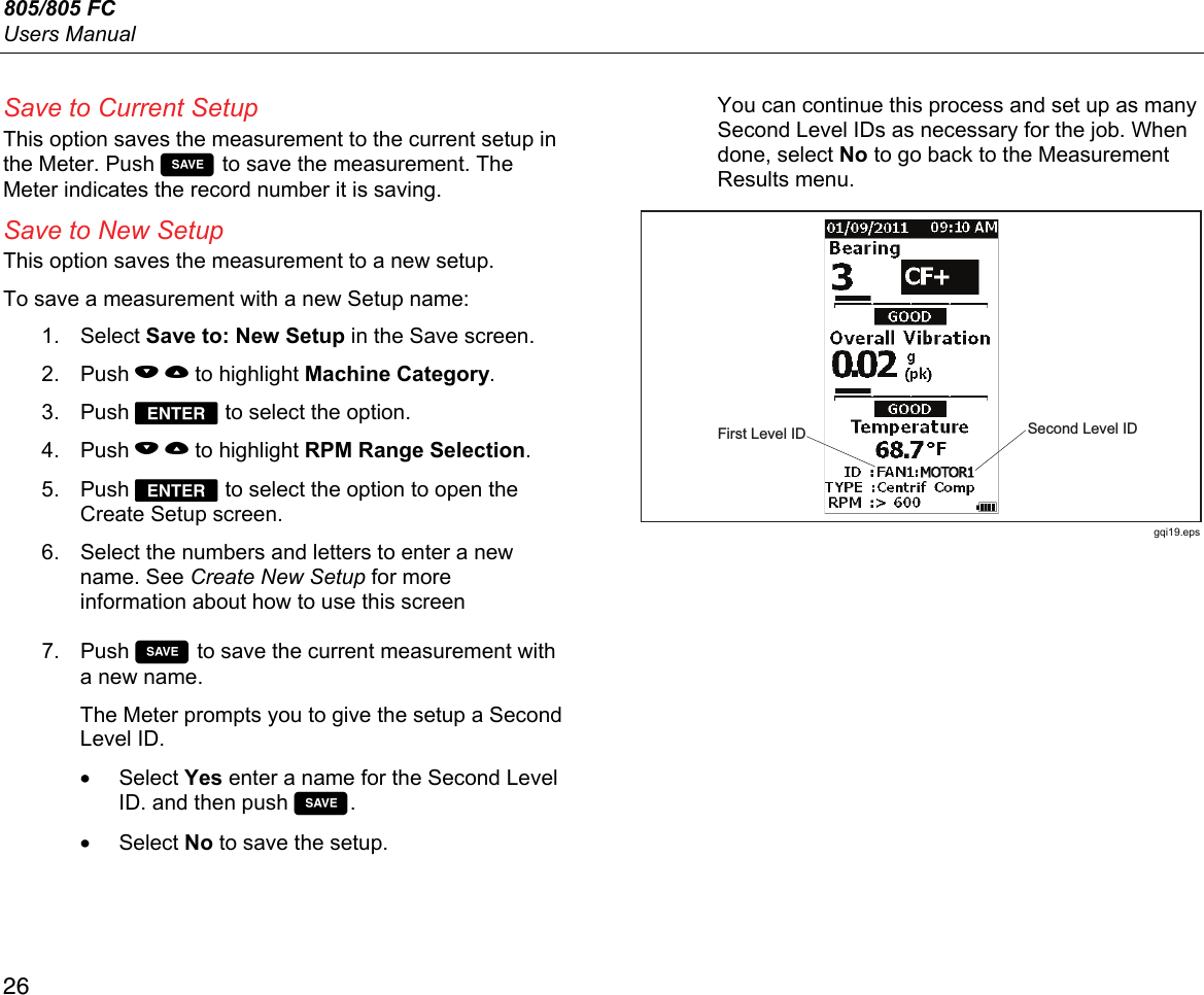
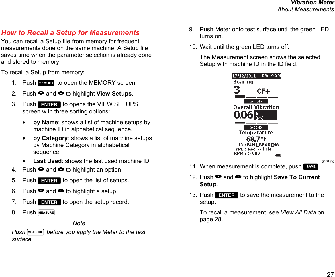
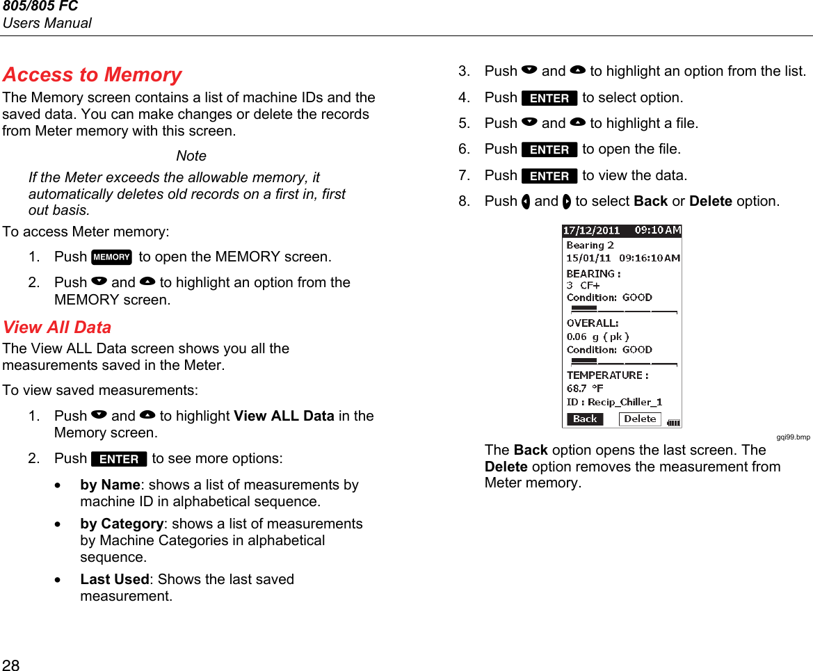
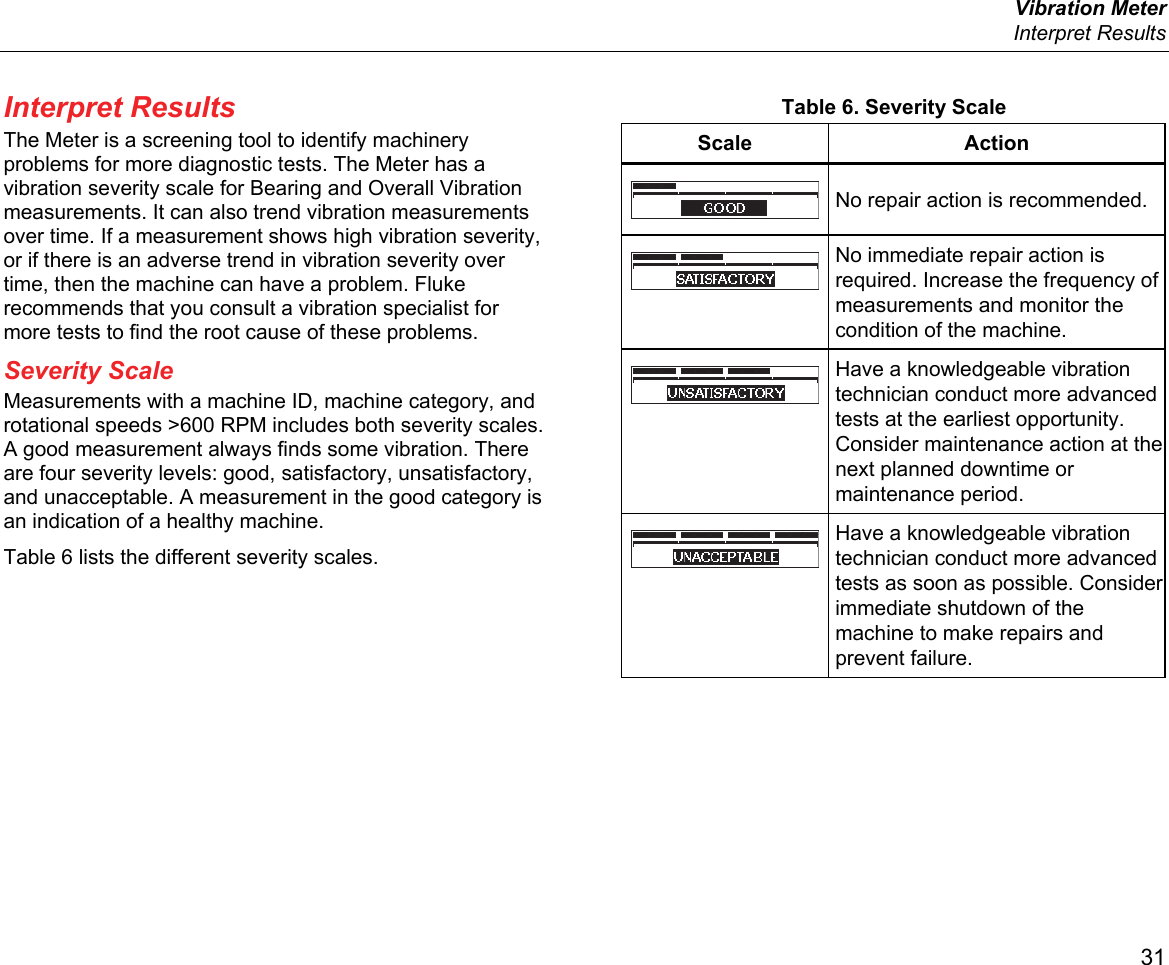
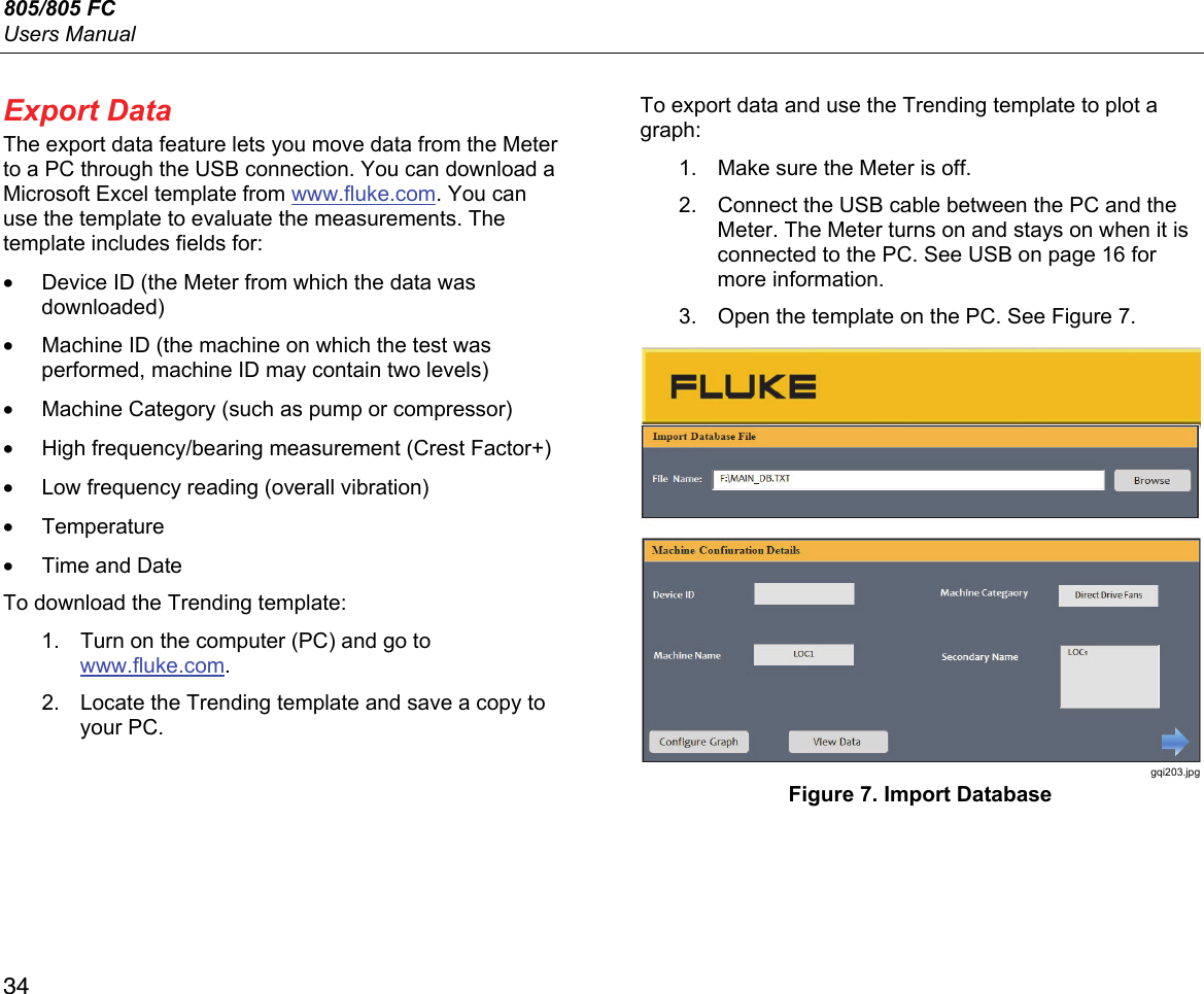
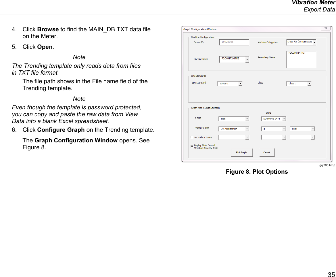
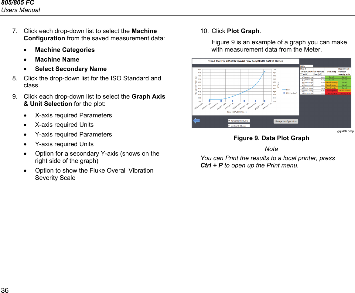
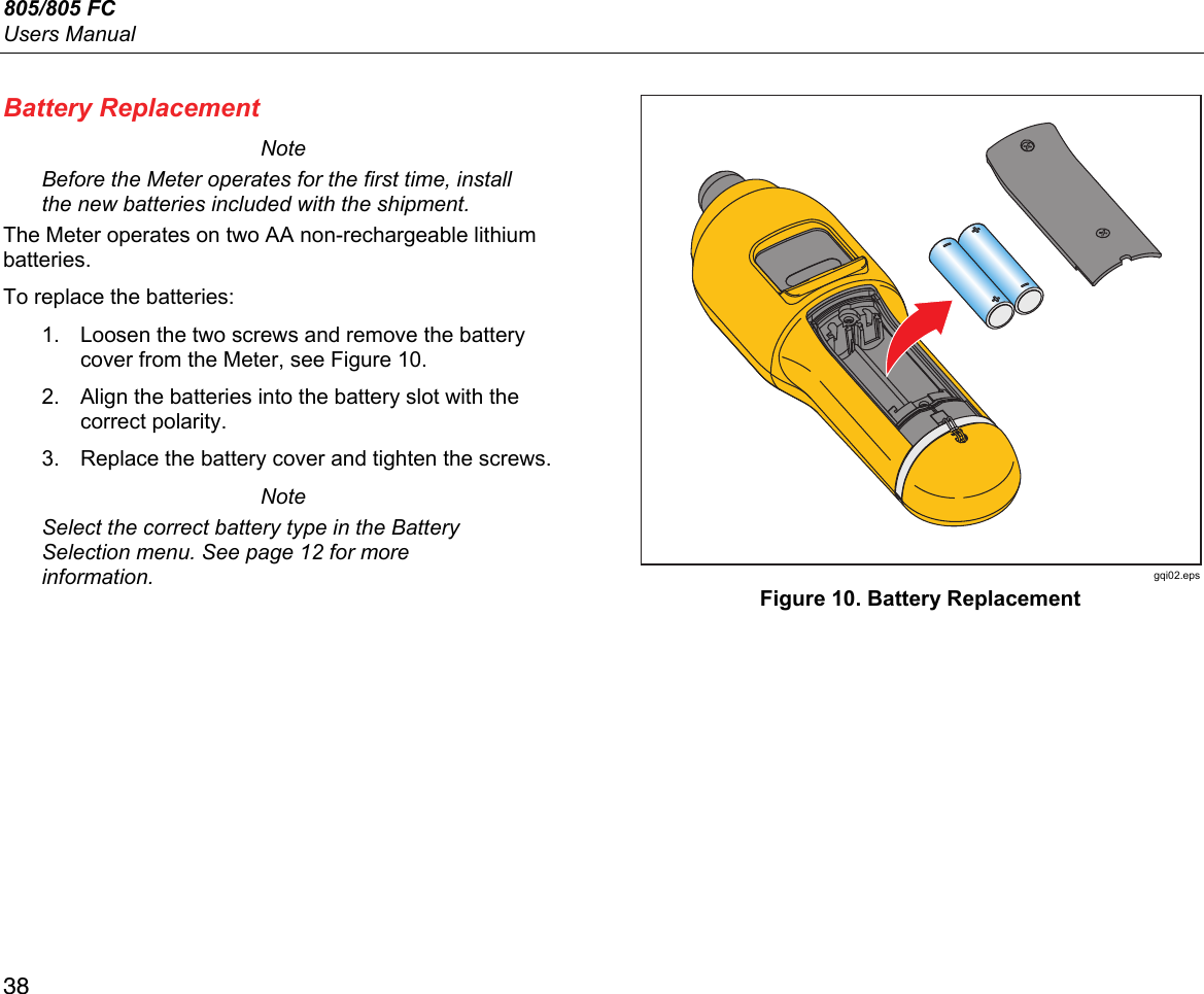
![805/805 FC Users Manual 40 How to Troubleshoot Table 8 is a list of problems, causes, and corrective actions for the Meter. Table 8. Troubleshooting Symptom Cause Corrective Action Meter does not turn on. • The battery voltage is too low. • The battery connection is loose. 1. Replace the batteries. See Battery Replacement on page 38 for more information. 2. Ensure the batteries are properly aligned and secured. 3. If the problem continues, contact the Fluke Service Center [1] for technical support. Buttons do not operate. Meter does not operate. 1. Restart the Meter. 2. If the problem continues, contact the Fluke Service Center [1] for technical support. The Meter cannot connect with the PC. The USB cable is not connected correctly. Correctly connect the USB cable. See USB on page 16 for more information. • The USB cable is damaged. • Check that USB drivers are installed in the PC/Laptop. 1. Examine the USB cable for any damage. If you find damage, contact the Fluke Service Center [1] for a replacement cable. 2. Reboot the PC. PC does not see the Meter is connected. Reboot the PC. Error Message: Measurement invalid. Please hold to surface for full duration. The Meter was not held on the surface for a sufficient time or with sufficient force. Push Meter onto test surface until green LED turns on. Wait until the green LED turns off. See About Measurements on page 17 for more information. [1] See How to Contact Fluke on page 1.](https://usermanual.wiki/Fluke-Electronics/805FC.User-Manual/User-Guide-2607272-Page-50.png)