Fluke Electronics 805FC Vibration Meter User Manual 2450AT42B100x
Fluke Electronics Vibration Meter 2450AT42B100x
UserManual.wiki
>
Fluke Electronics
>
805FC User Manual
>
Antenna Information
Contents
1.
User Manual
2.
RF Exposure Warning Statement
3.
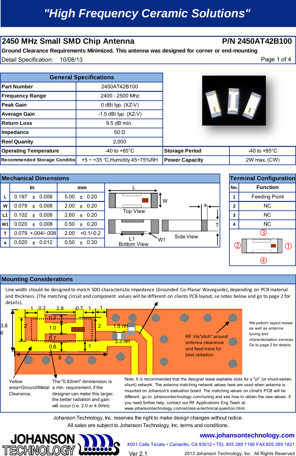
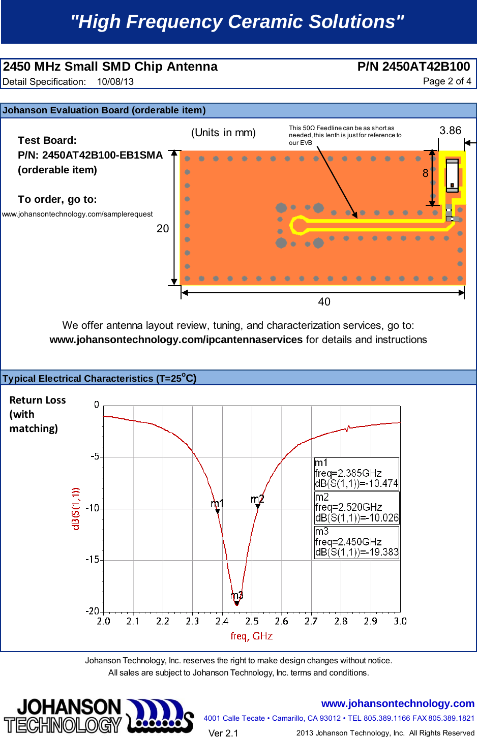
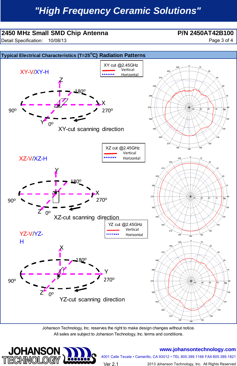
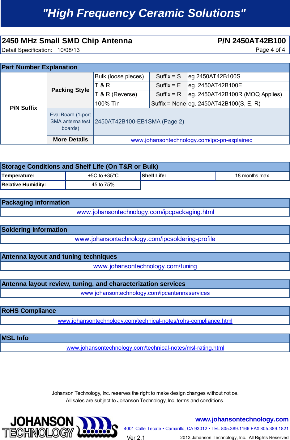
Antenna Information
Antenna Information
Navigation menu
Upload a User Manual
Namespaces
Wiki Guide
HTML
PDF
Info
Views
User Manual
Discussion / Help
Navigation