Fluke Electronics FLK1750 Power Recorder User Manual 0master
Fluke Electronics Power Recorder 0master
UserManual.wiki
>
Fluke Electronics
>
FLK1750 User Manual
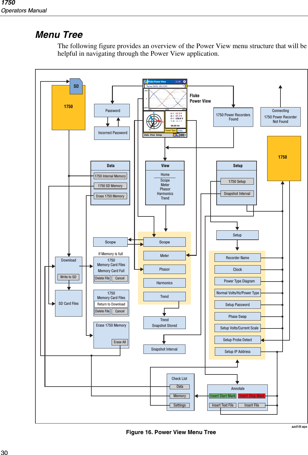
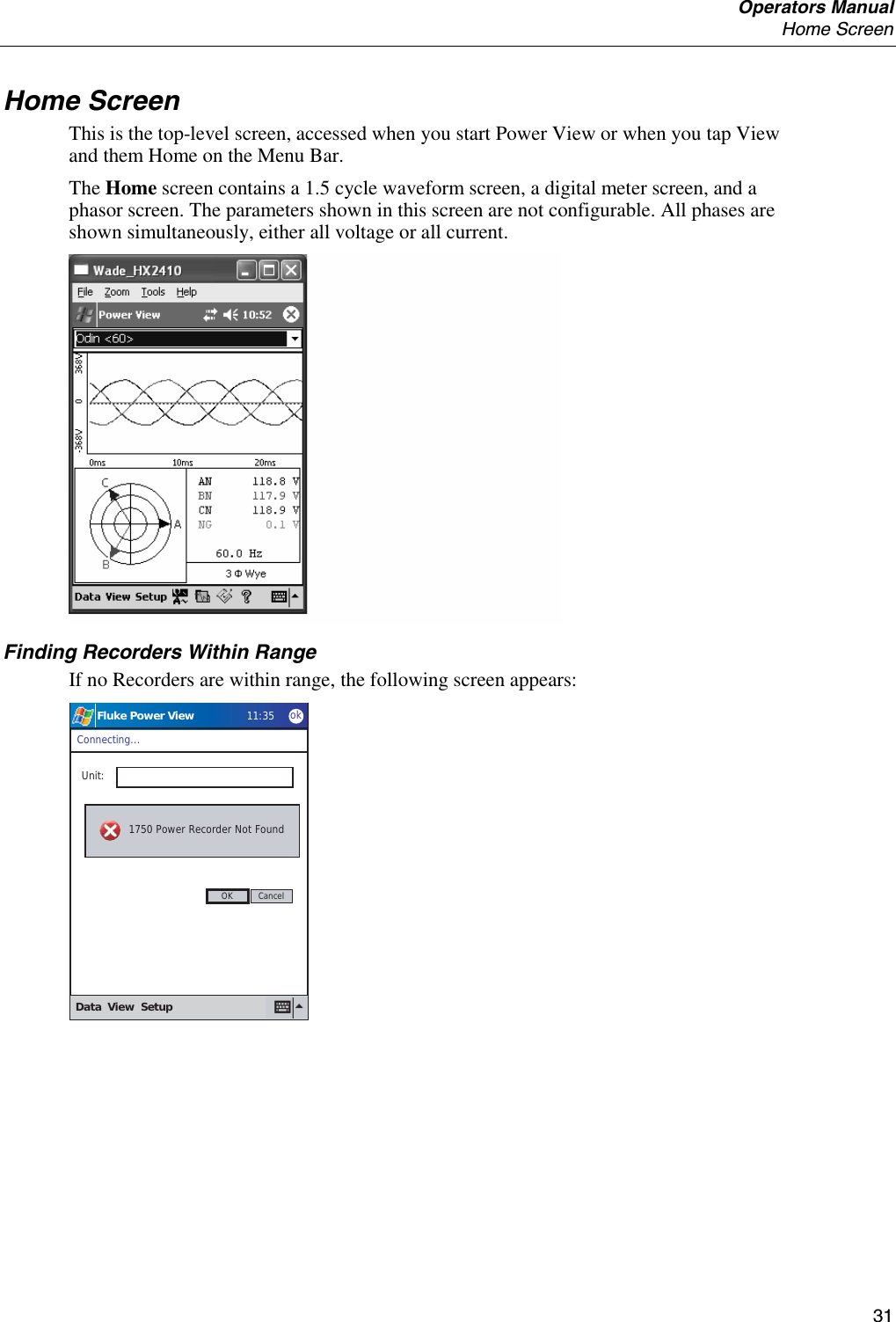
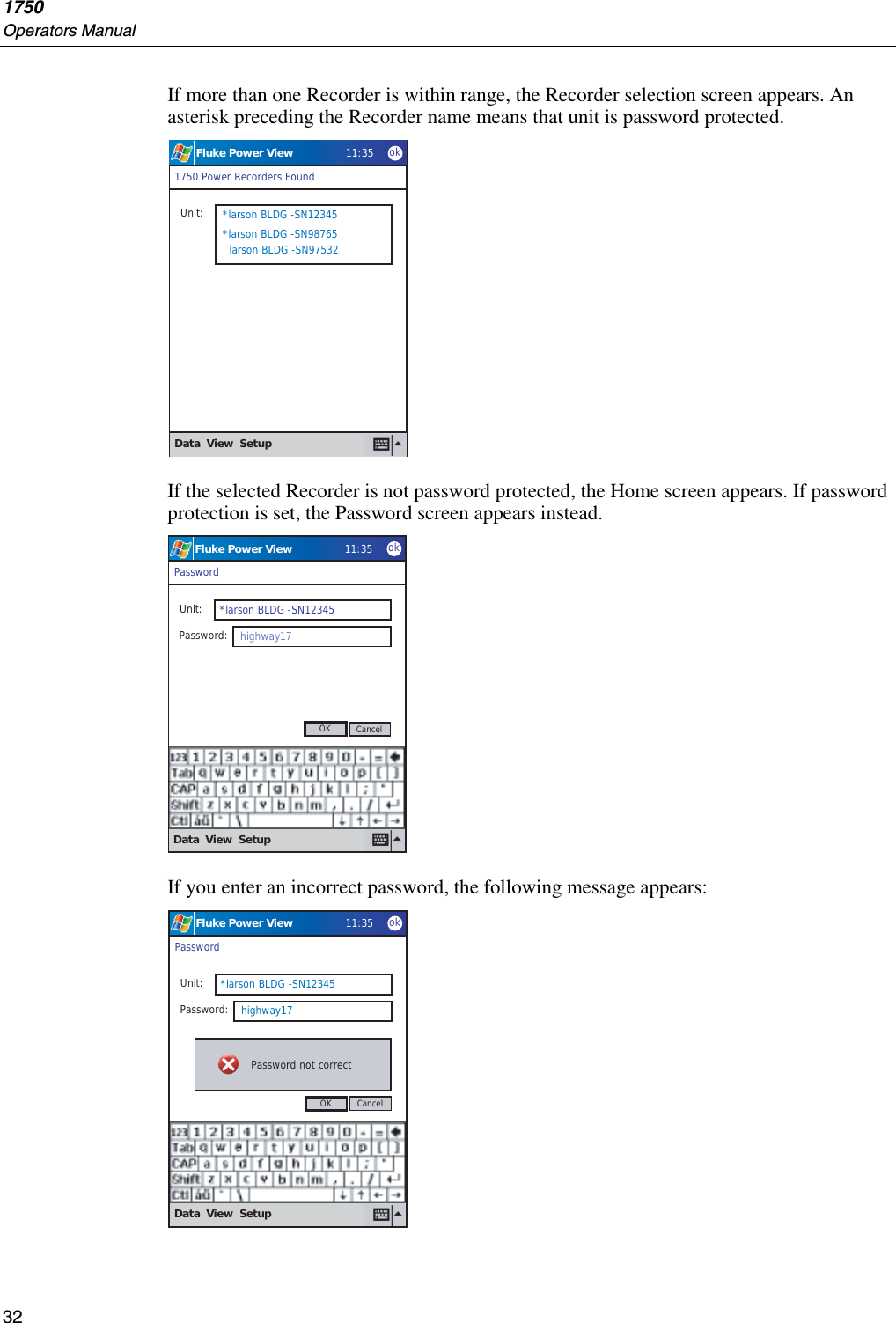
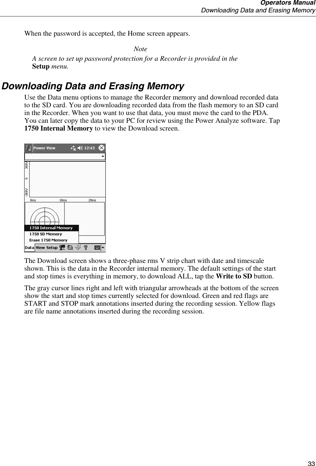
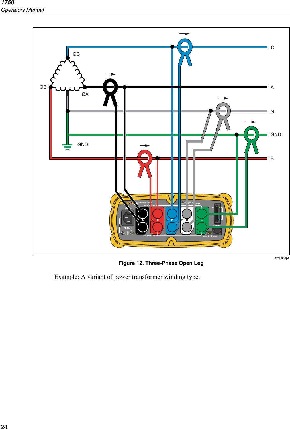
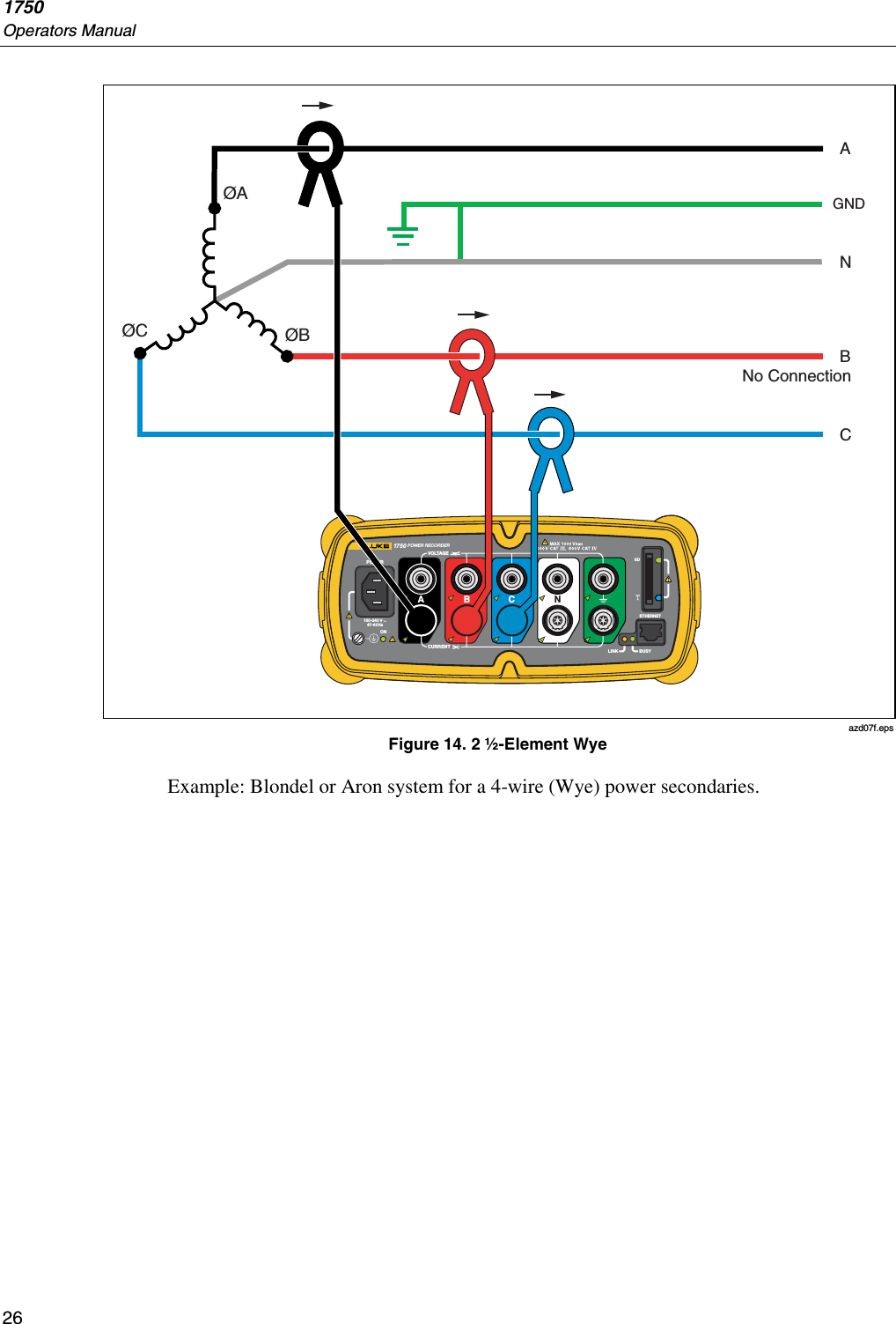
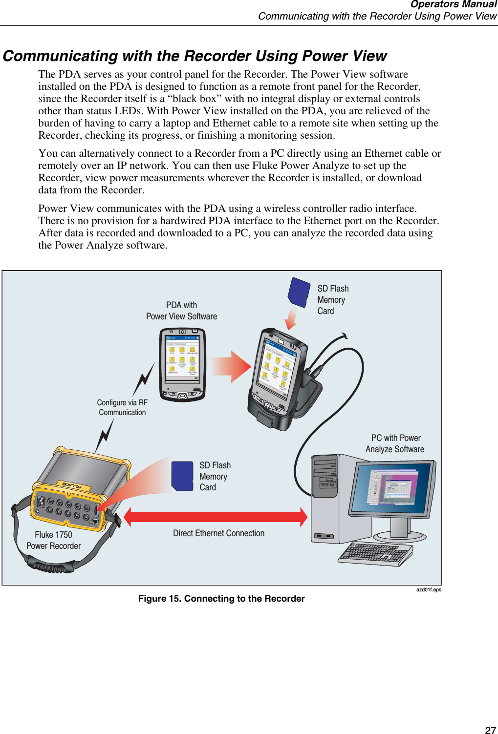
Users Manual
Navigation menu
Upload a User Manual
Namespaces
Wiki Guide
HTML
PDF
Info
Views
User Manual
Discussion / Help
Navigation

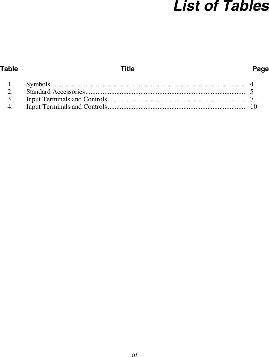

![1750 Operators Manual 4 Table 1. Symbols X Hazardous voltage. Risk of electrical shock. Precedes Warning WRisk of danger. Important information. See manual. Precedes Caution and Warning. P Conforms to requirements of European Union and European Free Trade Association (EFTA). ~ Do not dispose of this product as unsorted municipal waste. Contact Fluke or a qualified recycler for disposal. ) Canadian Standards Association. [ Note: Canadian and US. ] J Protective conductor terminal. CAT III CAT III equipment is designed to protect against transients in equipment in fixed-equipment installations, such as distribution panels, feeders and short branch circuits, and lighting systems in large buildings. CAT IVCAT IV equipment is designed to protect against transients from the primary supply level, such as an electricity meter or an overhead or underground utility service.](https://usermanual.wiki/Fluke-Electronics/FLK1750/User-Guide-705309-Page-12.png)


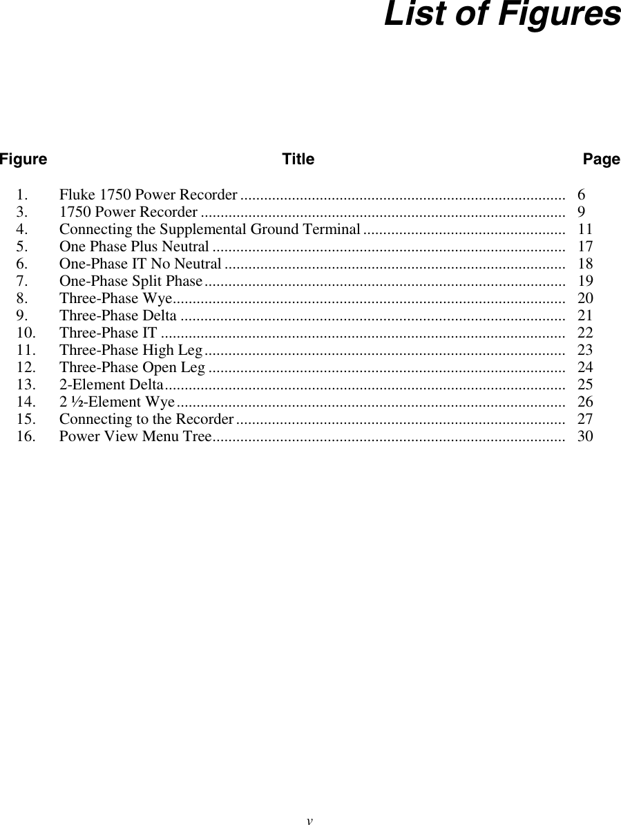
![Operators Manual Navigating in Power View on the PDA 29 This icon brings up the Annotate screen. Use the annotate menu to enter text or to insert a file and load it into the recorded data stream in the Recorder. Annotations can be used to make notes, or to insert an image or audio file name. You can enter multiple start and stop annotations. Start and stop annotations are not paired and are not restricted to being used as literally “start” and “stop”. Annotations are often done at the start of a power recording session. [keyboard] This icon brings up the standard PDA data entry keyboard.](https://usermanual.wiki/Fluke-Electronics/FLK1750/User-Guide-705309-Page-37.png)