Fluke Electronics FT560 TiX560, TiX520 User Manual 0master
Fluke Electronics TiX560, TiX520 0master
UserManual.wiki
>
Fluke Electronics
>
FT560 User Manual
>
Usres Manual
Contents
1.
Usres Manual
2.
Compliance Info Revised
3.
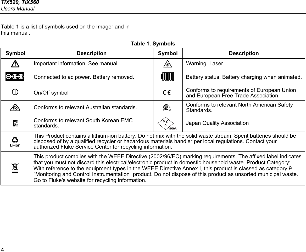
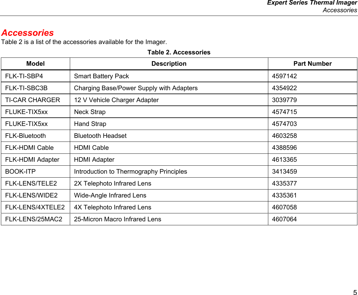
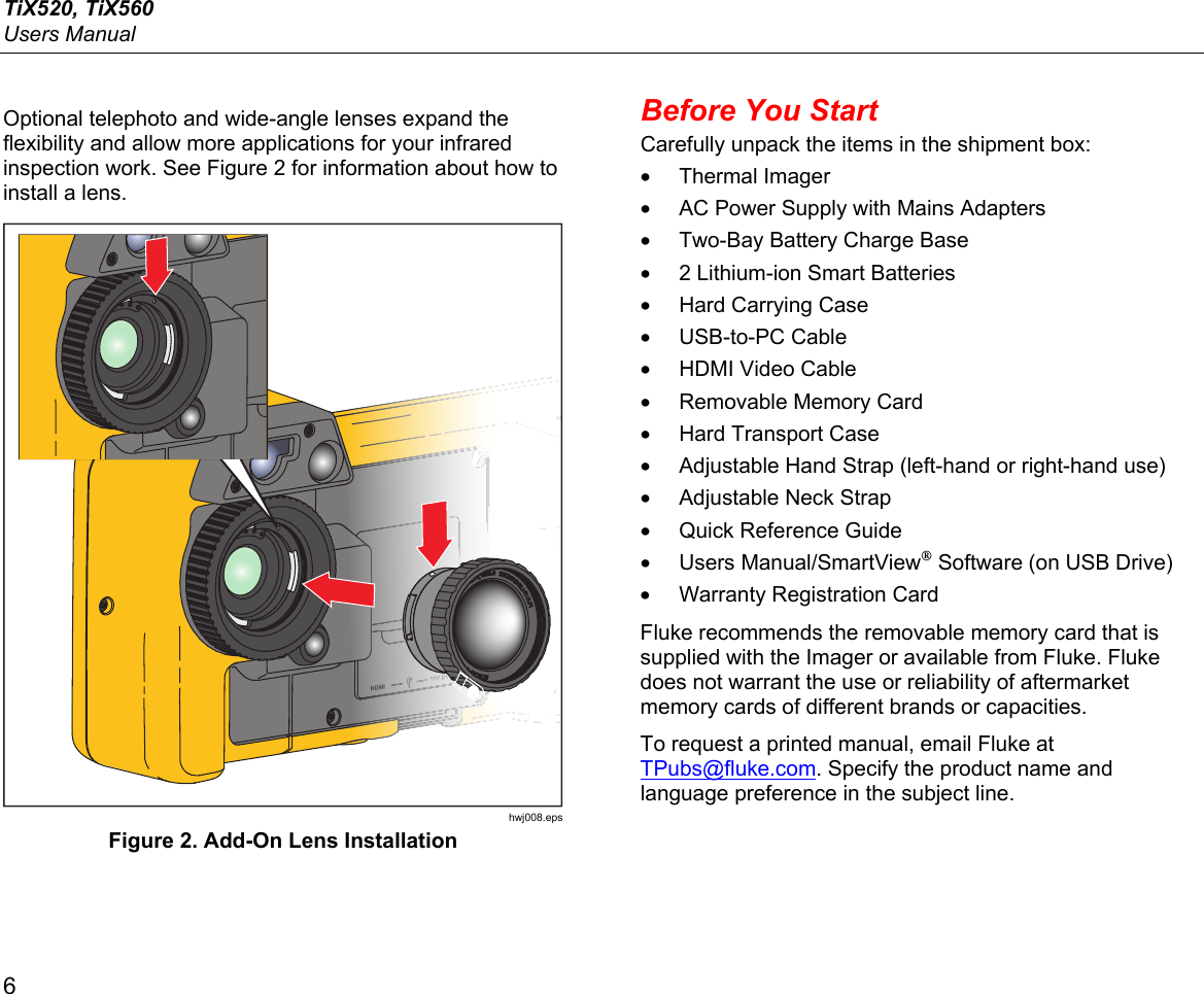
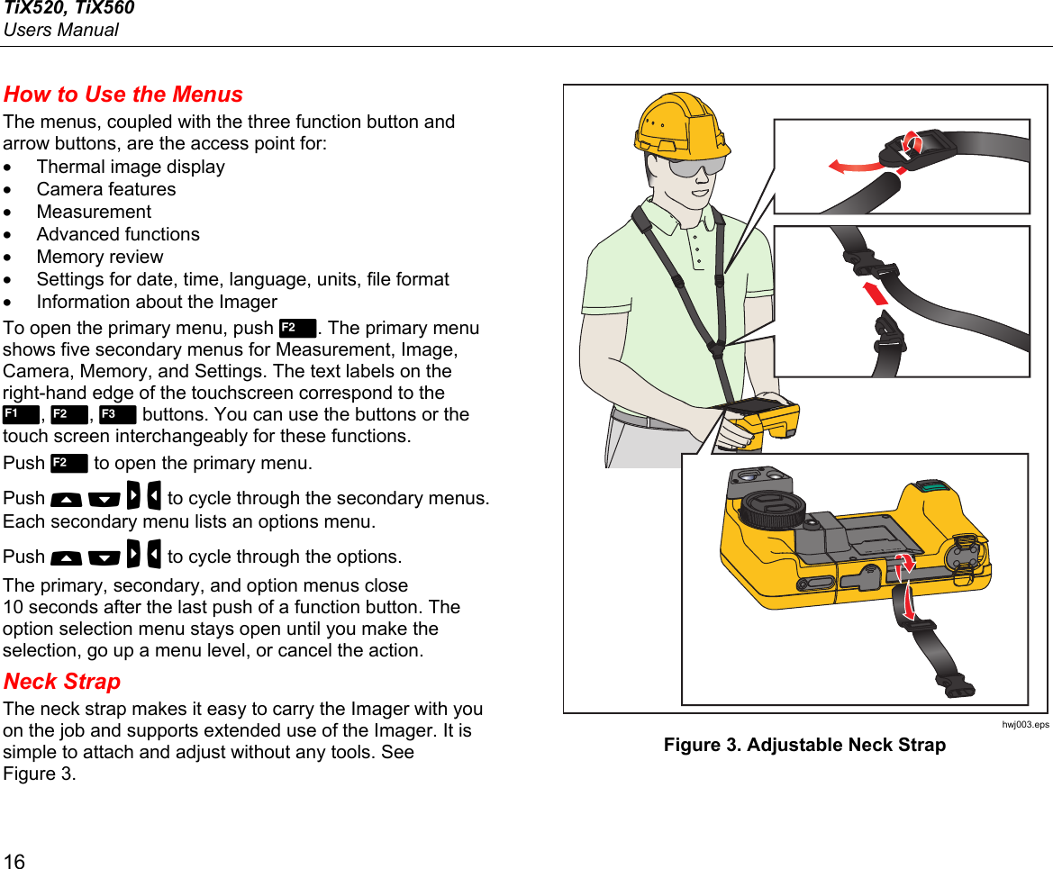
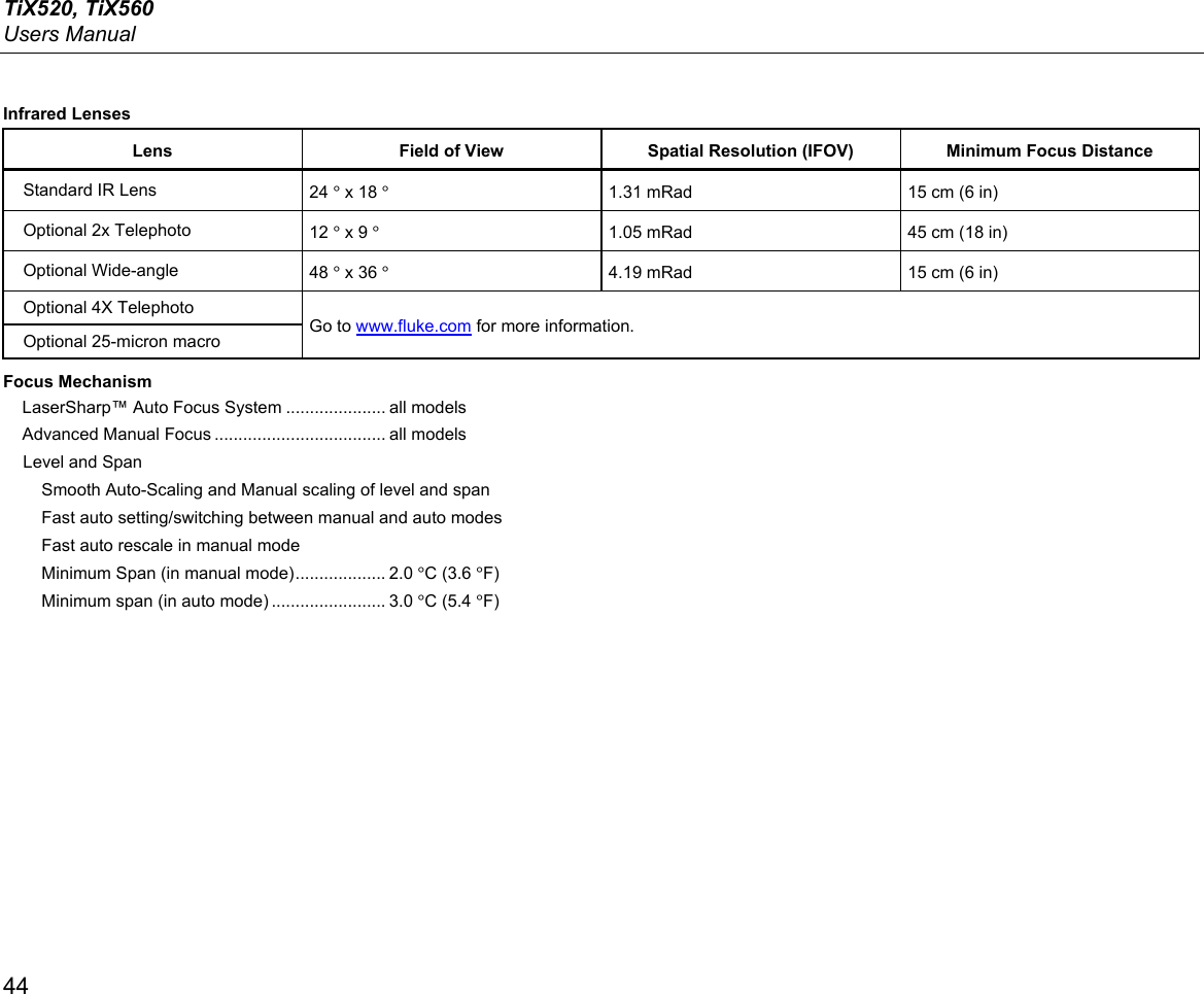
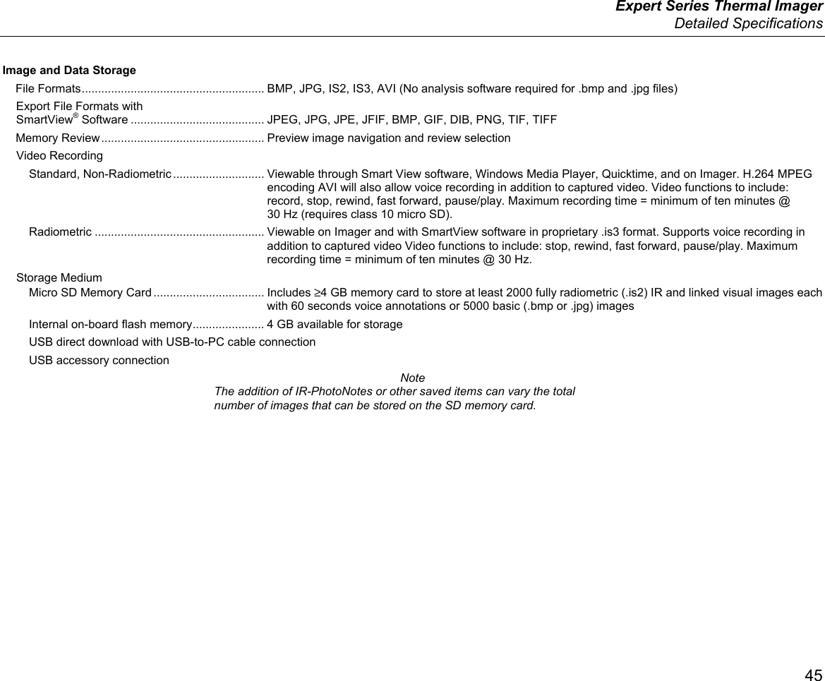
Users Manual
Usres Manual
Navigation menu
Upload a User Manual
Namespaces
Wiki Guide
HTML
PDF
Info
Views
User Manual
Discussion / Help
Navigation