Fluke Electronics FWCS Radio Module User Manual 0master
Fluke Electronics Radio Module 0master
UserManual.wiki
>
Fluke Electronics
>
FWCS User Manual
>
Users Manual
Contents
1.
User Manual
2.
Users Manual
Users Manual
Navigation menu
Upload a User Manual
Namespaces
Wiki Guide
HTML
PDF
Info
Views
User Manual
Discussion / Help
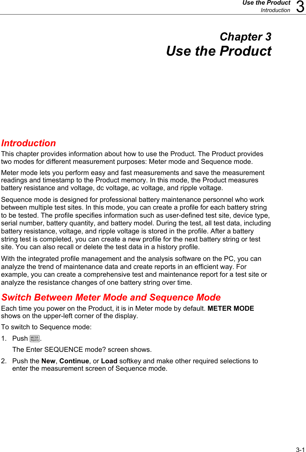
Navigation


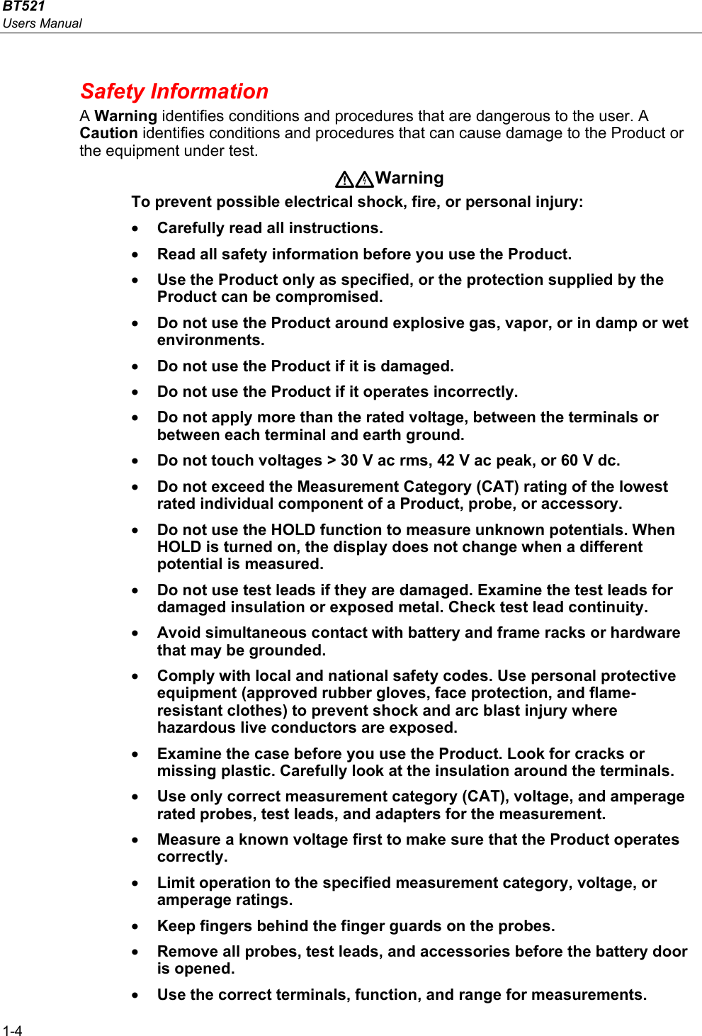
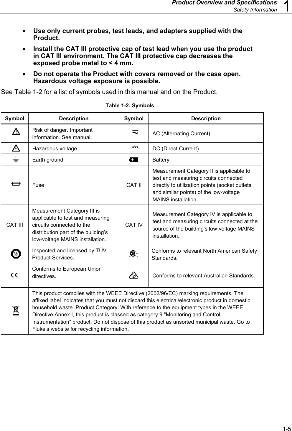
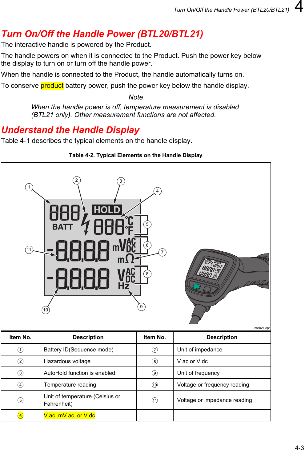
![Product Overview and Specifications Accuracy Specifications 1 1-9 Accuracy Specifications Accuracy is specified for a period of one year after calibration, at 18 °C to 28 °C (64 °F to 82 °F), with relative humidity to 80 %. Accuracy specifications are given as: ±([% of reading] + [number of least significant digits]). Accuracy specification assumes ambient temperature stable ±1 °C. Function Range Resolution Accuracy Battery Resistance[1] 3 mΩ 0.001 mΩ 1 % + 8 30 mΩ 0.01 mΩ 0.8 % + 6 300 mΩ 0.1 mΩ 0.8 % + 6 3000 mΩ 1 mΩ 0.8 % + 6 V dc 6 V 0.001 V 0.09 % +5 60 V 0.01 V 600 V 0.1 V 1000 V 1 V V ac (45 Hz to 500 Hz with low-pass filter) 600 V 0.1 V 2 % + 10 Frequency (Display with V ac) Trigger level: ≥ 10 mV @V ac; ≥ 10 A @A ac 45 Hz to 500 Hz 0.1 Hz 0.5 % + 8 AC Voltage Ripple (20 kHz max) 600 mV 6000 mV 0.1 mV 1 mV 3 % + 20 3 % + 10 Amps dc/Amps ac (With accessory Fluke i410) 400 A 1 A 3.5 % + 2 Temperature 0 °C to 60 °C 1 °C ±2 °C [1] The measurement is based on ac injection method. The injected source signal is <100 mA, 1 kHz.](https://usermanual.wiki/Fluke-Electronics/FWCS.Users-Manual/User-Guide-2252469-Page-19.png)