Fluke 807 0115 Users Manual Datasheet_4xT1_E1
807-0115 to the manual 92c5ec97-8279-4796-8a0a-99ef4be151f0
2015-02-02
: Fluke Fluke-807-0115-Users-Manual-427831 fluke-807-0115-users-manual-427831 fluke pdf
Open the PDF directly: View PDF ![]() .
.
Page Count: 34
- 4xT1/E1 inline ASE Model 115
- T1/E1 inline ASE Model 113
- 10/100 Ethernet inline ASE Model 120
- 10/100 Ethernet inline ASE Model 122
- 10/100/1000 Ethernet ASE Model 220
- HSSI inline ASE Model 106
- V35 inline ASE Model 104
- X21 inline ASE Model 105
- DS3 inline ASE Model 200
- E3 inline ASE Model 201
- OC3 inline ASE Model 202 (single-mode)
- OC3 inline ASE Model 203 (multi-mode)
- T1 CSU/DSU Model 109 (with DSX)
- T1 CSU/DSU Model 110
- T1 CSU/DSU Model 111 (with modem)
- T1 CSU/DSU Model 112 (with modem and DSX)
- T1 CSU/DSU Model 100 (dual-port dual-analysis)
Technical Data
4xT1/E1 i nline probe ASE
With LinkSafe capabilities
Key features
Four management ports
MLPPP support on IP Transport software
Inband management capability
LinkSafe technology
Power loss detection
Service Level Agreement (SLA) metrics
Application analysis capability
LMI spoofi ng
LAN management port
Realtime events
•
•
•
•
•
•
•
•
•
•
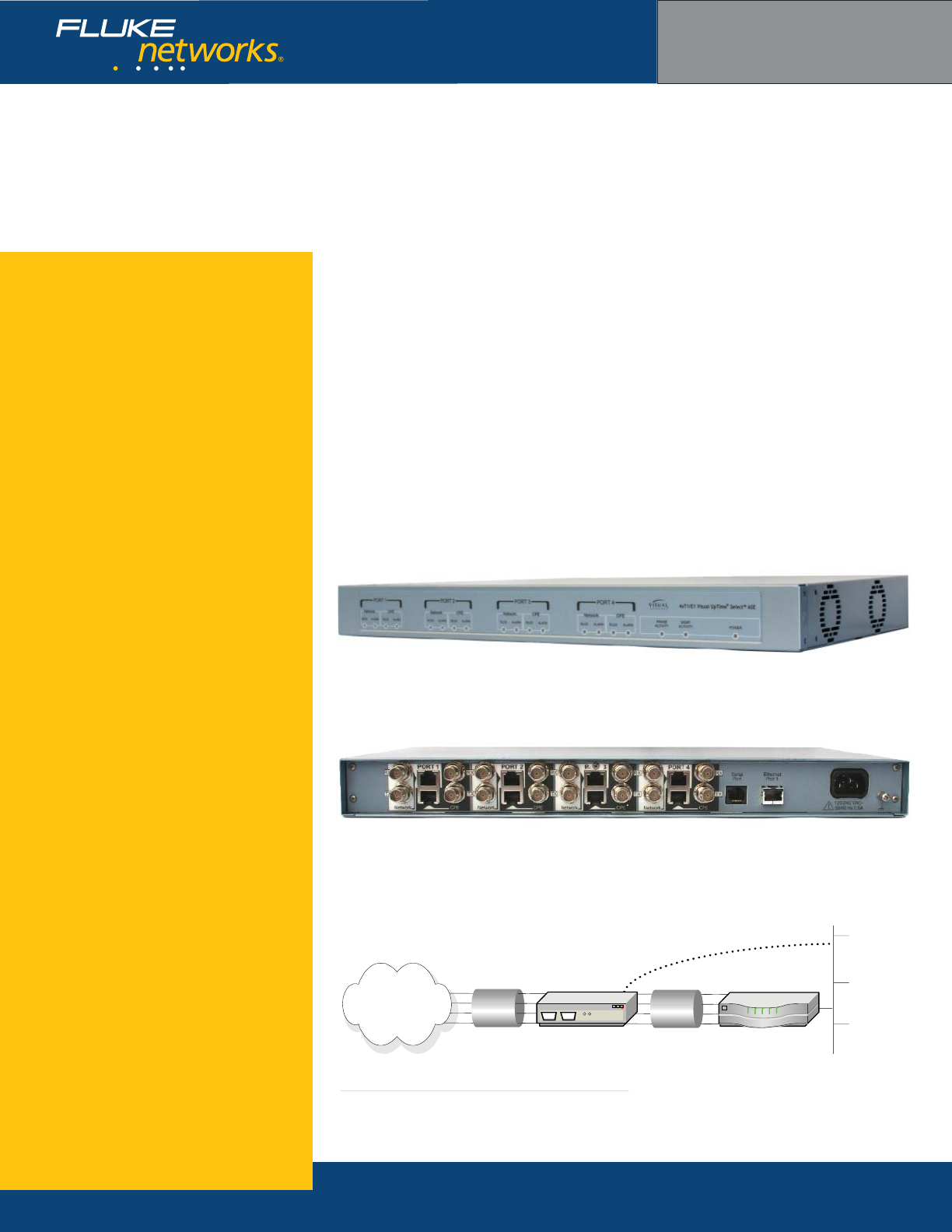
The Visual UpTime® Select™ 4xT1/E1 inline probe
ASE enhances the data analysis functionality of the
Visual UpTime Select system for enterprises with
two-to-four T1 or E1 circuits terminating at a single
location. The ASE provides up to 6.176 Mbps
(T-standard) or 8.192 Mbps (E-standard) of detailed
network traffi c analysis and management, while
maintaining full wire speed pass-through of all
traffi c. In its initial release, the ASE supports IP
Transport software over MultiLink Point-to-Point
Protocol (MLPPP) T1 links.
The 4xT1/E1 ASE includes LinkSafe™ technology
to protect circuit integrity in case of a power outage
and it also delivers a notifi cation alarm if there is a
power failure.
Designed for locations with multiple circuits
terminating at a single device, the 4xT1/E1 is typi-
cally deployed as an inline probe between the service
provider’s edge device and the customer’s termination
equipment. The fi gure below highlights the multilink
deployment for the 4xT1/E1 ASE.
4xT1/E1 inline probe model model 807-0115 rear
4xT1/E1 inline probe model 807-0115 front
4xT1/E1 inline probe model 807-0115 position on network
Visual UpTime Select
ASE model 807-0115
Bundled
T1 Line
LAN
4xT1/E1 inline ASE
Optional LAN Connection
CPE Router
WAN

NETWORKSUPERVISION
Fluke Networks
P.O. Box 777, Everett, WA USA 98206-0777
Fluke Networks operates in more than 50 countries
worldwide. To fi nd your local offi ce contact details, go to
www.fl ukenetworks.com/contact.
©2006 Fluke Corporation. All rights reserved.
Printed in U.S.A. 2/2006 2643418 D-ENG-N Rev A
What are ASEs?
ASEs (Analysis Service Elements) are data
collection and network performance monitor-
ing hardware devices placed on a wide area
network (WAN) or Local Area Network (LAN)
as part of the Visual UpTime Select system,
which offers in-depth, real-time, and historical
visibility into the performance of your
applications infrastructure. In the system,
data gathered by ASEs is stored in the Visual
UpTime Select server and displayed and ana-
lyzed from the Visual UpTime Select Web client.
As a service level management tool, ASEs
indicate when services are being met, provide
warnings when services start to degrade, and
send alerts when services are not met.
Hardware Warranties
Enhanced Gold, Bronze, and International
Gold ASE hardware warranty service programs
are available to help you maximize your
investment in Visual UpTime Select. For more
detailed warranty information, visit:
www.fl ukenetworks.com/visualcustomercare
Ordering Information
For more details, please contact your Visual
UpTime Select authorized reseller or
Fluke Networks Sales at (800) 240-4010
or (301) 296-2300.
4xT1/E1 inline probe ASE specifcations
General Dimensions 8.16” (20.7 cm) x 9.0” (22.8 cm) x 1.62”(4.1 cm)
Weight 7 lbs.
Data Rate T1: 1.536 Mbps, E1: 1.984 Mbps
Timing Mode Derived externally from the T1 or E1 network,
user interface, or internally from the ASE.
Environment Operating Temperature 0o to +40oC (+32o to +104o F)
Storage Temperature -20o to +55oC (-4o to +131o×F)
Clearance Requirement Minimum of 3” (7.62 cm) space on sides.
Operating and Storage
Humidity
10% to 80%, noncondensing
Power Requirements Input 100 to 240 VAC
Frequency 50/60 Hz
Input Current Rating 0.5 amps
T1 Network Interface
(Ports 1-4)
Line Rate 1.544 Mbps ±50 bps synchronous
Line Format B8ZS line coding
Framing ESF framing formats
Input Signal 0dB to -36dB
Output Signal 0, -7.5dB, -15dB, -22.5dB LBO
Pulse Density AT&T 62411
Connector 100 ohm 8-pin modular jack—USOC: RJ48C
Timing Network or User
Channel Selection 1 to 24 channels in any combination
E1 Network Interface
(Ports 1-4)
Line Rate 2.048 Mbps ±102.4 bps synchronous
Line Format HDB3 line coding
Framing CRC4 or FAS framing formats
Time Slot 16 CAS, CCS, or Data
Input Signal 0dB to -43dB
Output Signal 0dB
Connector 120 ohm RJ-48C balanced and 75 ohm BNC unbal-
anced coaxial
Channel Selection 1-31 (includes channel 16) or 1-15, 17-31 (does
not include channel 16)
Serial Port Interface Baud Rate 19200 or 9600 bps
Parity 8 data bits, no parity
Stop Bit 1 stop bit
Electrical Format EIA RS-232, DTE
Connector RJ-45
Ethernet 10/100BaseT
Interface
Bite Rate 10 or 100 Mbps
Connector 8-pin modular jack: RJ-48
Technical Data
T1/E1 i nline probe ASE
With LinkSafe capabilities
Key features
Inband management capabilities
LinkSafe technology
Power loss detection
Multi-Protocol or IP Transport software
Service Level Agreement (SLA) metrics
Voice over IP (VoIP) analysis capability
Application analysis capability
LMI spoofi ng
LAN management port
Realtime events
•
•
•
•
•
•
•
•
•
•
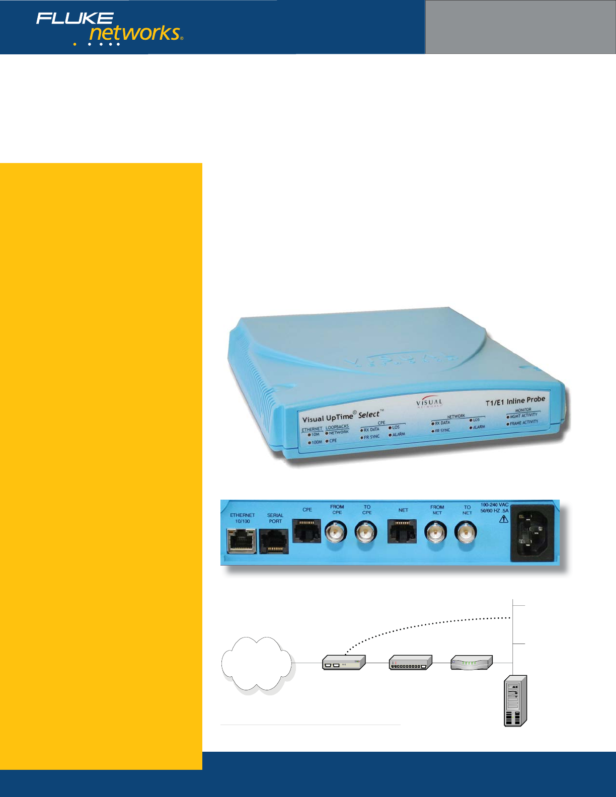
The Visual UpTime® Select™ T1/E1 LinkSafe™ inline
probe ASE is deployed inline on a T1 or E1 access line,
typically between a service provider’s edge device and
CSU/DSU. This ASE supports Multi-Protocol software
for deployment in standard frame relay or HDLC
networks and IP Transport software for deployment
in frame relay or HDLC-based networks that use IP
switching. The ASE also includes LinkSafe technology
to protect circuit integrity in case of an ASE outage,
as well as power failure notifi cation.
When confi gured for use on an E1 network, the ASE
complies with the physical/electrical characteristics
defi ned by ITU-T G.703 at 2.048 Megabits per second
(Mbps). The ASE also complies with the synchronous
frame structure specifi cations defi ned by ITU-T G.704,
including the option to use channel 16 for data or
signalling. You can either connect to the E1 network
using a 120 ohm balanced cable or BNC coax 75 ohm
unbalanced cables.
T1/E1 inline probe model model 807-0113 rear view
T1/E1 inline probe model 807-0113 front view
T1/E1 inline probe model 807-0113 position on network
Visual UpTime Select
ASE model 807-0113
T1/E1 Access Line
LAN
T1/E1 inline ASE
Optional LAN Connection
CPE Router
Visual UpTime
Select Server
WAN
CSU/DSU

NETWORKSUPERVISION
Fluke Networks
P.O. Box 777, Everett, WA USA 98206-0777
Fluke Networks operates in more than 50 countries
worldwide. To fi nd your local offi ce contact details, go to
www.fl ukenetworks.com/contact.
©2006 Fluke Corporation. All rights reserved.
Printed in U.S.A. 2/2006 2643532 D-ENG-N Rev A
What are ASEs?
ASEs (Analysis Service Elements) are data
collection and network performance monitor-
ing hardware devices placed on a wide area
network (WAN) or Local Area Network (LAN)
as part of the Visual UpTime Select system,
which offers in-depth, real-time, and historical
visibility into the performance of your
applications infrastructure. In the system,
data gathered by ASEs is stored in the Visual
UpTime Select server and displayed and ana-
lyzed from the Visual UpTime Select Web client.
As a service level management tool, ASEs
indicate when services are being met, provide
warnings when services start to degrade, and
send alerts when services are not met.
Hardware Warranties
Enhanced Gold, Bronze, and International
Gold ASE hardware warranty service programs
are available to help you maximize your
investment in Visual UpTime Select. For more
detailed warranty information, visit:
www.fl ukenetworks.com/visualcustomercare
Ordering Information
For more details, please contact your Visual
UpTime Select authorized reseller or
Fluke Networks Sales at (800) 240-4010
or (301) 296-2300.
T1/E1 inline probe ASE specifcations
General Dimensions 8.16” (20.7 cm) x 9.0” (22.8 cm) x 1.62”(4.1 cm)
Weight 2.10 lbs.
Data Rate 1.544 Mbps synchronous
Timing Mode Derived externally from the T1 or E1 network,
user interface, or internally from the ASE.
Environment Operating Temperature 0o to +40oC (+32o to +104o F)
Storage Temperature -20o to +55oC (-4o to +131o×F)
Clearance Requirement Minimum of 3” (7.62 cm) space on sides.
Operating and Storage
Humidity
10% to 80%, noncondensing
Power Requirements Input 100 to 240 VAC
Frequency 50/60 Hz
Input Current Rating 0.5 amps
T1 Network Interface Line Rate 1.544 Mbps ±50 bps synchronous
Line Format AMI or B9ZS line coding
Framing ESF or D4 framing formats
Input Signal 0dB to -36dB
Output Signal 0, -7.5dB, -15dB, -22.5dB LBO
Pulse Density AT&T 62411
Connector 8-pin modular jack—USOC: RJ48C
Timing Network, User, or Internal
Channel Selection 1 to 24 channels in any combination
E1 Network Interface Line Rate 2.048 Mbps ±102.4 bps synchronous
Line Format HDB3 or AMI line coding
Framing CRC4 or FAS framing formats
Time Slot 16 CAS, CCS, or Data
Input Signal 0dB to -43dB
Output Signal 0dB to LBO
Connector RJ-45 (100 ohm balanced)
or BNC (75 ohm unbalanced)
Channel Selection 1-31 (includes channel 16
or 1-15, 17-31 (does not include channel 16)
Serial Port Interface Baud Rate 19200 or 9600 bps
Parity 8 data bits, no parity
Stop Bit 1 stop bit
Electrical Format EIA RS-232, DTE
Connector RJ-45
Ethernet 10/100BaseT
Interface
Bite Rate 10 or 100 Mbps
Connector 8-pin modular jack: RJ-48
Technical Data
10/100 Ethernet i nline ASE LE
With LinkSafe capabilities
Key features
Inline or SPAN mode deployment
LinkSafe technology
IP Transport or LAN Visibility software
Voice over IP (VoIP) analysis capability
Application analysis capability
LAN management port
Power loss detection
Realtime events
•
•
•
•
•
•
•
•
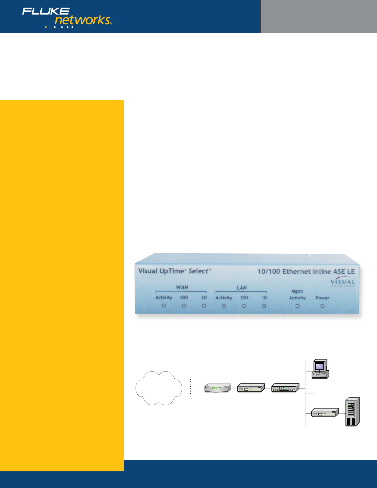
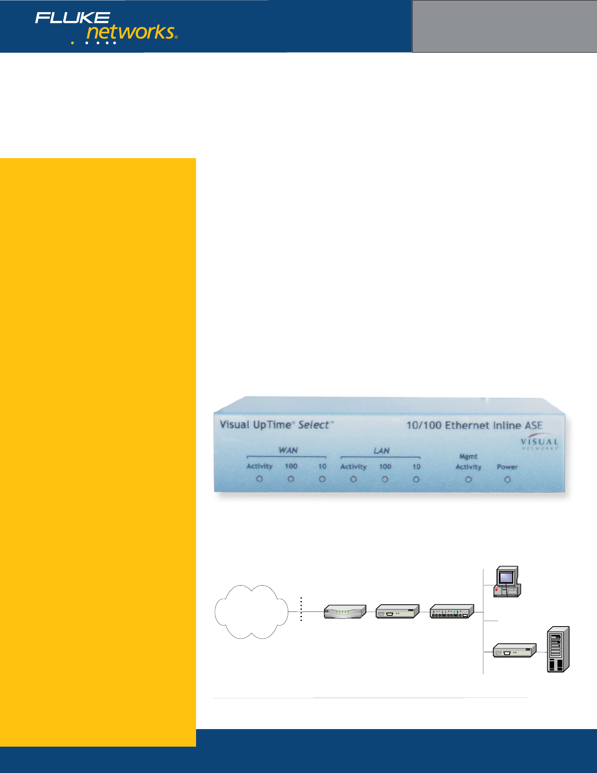
The Visual UpTime® Select™ 10/100 Ethernet
inline ASE LE enhances the analysis functionality
of the Visual UpTime Select system for Ethernet
networks. The ASE provides up to 6 Mbps of detailed
network traffi c analysis and management, while
maintaining full wire speed pass-through of all traf-
fi c. It supports both IP Transport and LAN Visibility
software When deployed inline, the ASE includes
LinkSafe™ technology to protect circuit integrity if
in case of an ASE outage, as well as power failure
notifi cation.
Designed for business class DSL and cable, the
10/100 Ethernet inline ASE LE has a wide variety of
deployment options. The IP Transport Ethernet ASE is
typically deployed as an inline probe on the access
line between LAN devices, such as the LAN switch
and router (see fi gure). Other options include posi-
tioning the ASE on the Ethernet segment between a
subscriber’s router and a Network Terminating Unit
(NTU) such as a DSL modem or a Service Provider
switch (Ethernet as WAN access), or connecting the
ASE to a router or switch SPAN port.
The LAN Visibility Ethernet ASE is deployed on
the LAN. The inline LAN Visibility ASE collects and
displays application fl ow traffi c on the LAN between
clients and application server. In contrast, the IP
Transport ASE is designed to display only traffi c to or
from the WAN, and ignore local traffi c (such as be-
tween a client and an Internet or application server).
Ethernet inline probe model 807-0120 front view
Visual UpTime Select
ASE model 807-0120
Ethernet inline probe model 807-0120 deployed inline IP Transport and on LAN in LAN Visibility mode
Access
Line(s)
LAN
IP Transport
Ethernet ASE
Customer
Edge Router
Wide Area
Network
LAN Switch
LAN Visibility
Ethernet ASE
NTU
device
Client
Server
NETWORKSUPERVISION
Fluke Networks
P.O. Box 777, Everett, WA USA 98206-0777
Fluke Networks operates in more than 50 countries
worldwide. To fi nd your local offi ce contact details, go to
www.fl ukenetworks.com/contact.
©2006 Fluke Corporation. All rights reserved.
Printed in U.S.A. 2/2006 2643441 D-ENG-N Rev A
What are ASEs?
ASEs (Analysis Service Elements) are data
collection and network performance monitor-
ing hardware devices placed on a wide area
network (WAN) or Local Area Network (LAN)
as part of the Visual UpTime Select system,
which offers in-depth, real-time, and historical
visibility into the performance of your
applications infrastructure. In the system,
data gathered by ASEs is stored in the Visual
UpTime Select server and displayed and ana-
lyzed from the Visual UpTime Select Web client.
As a service level management tool, ASEs
indicate when services are being met, provide
warnings when services start to degrade, and
send alerts when services are not met.
Hardware Warranties
Enhanced Gold, Bronze, and International
Gold ASE hardware warranty service programs
are available to help you maximize your
investment in Visual UpTime Select. For more
detailed warranty information, visit:
www.fl ukenetworks.com/visualcustomercare
Ordering Information
For more details, please contact your Visual
UpTime Select authorized reseller or
Fluke Networks Sales at (800) 240-4010
or (301) 296-2300.
Ethernt inline probe ASE specifcations
General Dimensions 7.5” (19.1 cm) x 6” (15.2 cm) x 1.5” (3.8 cm)
Weight 2.10 lbs.
Maximum Data Rate 6 Mbps
Environment Operating Temperature 0o to +40oC (+32o to +104o F)
Storage Temperature -20o to +55oC (-4o to +131o×F)
Clearance Requirement Minimum of 3” (7.62 cm) space on sides.
Power Requirements Input 100 to 240 VAC
Frequency 50/60 Hz
Input Current Rating 0.5 amps
LAN and WAN
Ethernet Interface
Bit Rate 10/100 Mbps
Connector 8-pin modular jack: RJ-45
Serial Port Interface Baud Rate 19200 or 9600 bps
Parity 8 data bits, no parity
Stop Bit 1 stop bit
Electrical Format EIA RS-232, DTE
Connector RJ-45
Ethernet inline probe model model 807-0120 rear view
Technical Data
10/100 Ethernet i nline ASE
With LinkSafe capabilities
Key features
Inline or SPAN mode deployment
LinkSafe technology
IP Transport or LAN Visibility software
Voice over IP (VoIP) analysis capability
Application analysis capability
Power loss detection
LAN management port
Realtime events
•
•
•
•
•
•
•
•
The Visual UpTime® Select™ 10/100 Ethernet
inline ASE enhances the analysis functionality of the
Visual UpTime Select system for Ethernet networks.
The ASE provides up to 100 Mbps of detailed network
traffi c analysis and management, while maintaining
full wire speed pass-through of all traffi c. It supports
both IP Transport and LAN Visibility software When
deployed inline, the ASE includes LinkSafe™ technol-
ogy to protect circuit integrity if in case of an ASE
outage, as well as power failure notifi cation.
Designed for business class DSL and cable, the
10/100 Ethernet inline ASE has a wide variety of
deployment options. The IP Transport Ethernet ASE is
typically deployed as an inline probe on the access
line between LAN devices, such as the LAN switch
and router (see fi gure). Other options include posi-
tioning the ASE on the Ethernet segment between a
subscriber’s router and a Network Terminating Unit
(NTU) such as a DSL modem or a Service Provider
switch (Ethernet as WAN access), or connecting the
ASE to a router or switch SPAN port.
The LAN Visibility Ethernet ASE is deployed on
the LAN. The inline LAN Visibility ASE collects and
displays application fl ow traffi c on the LAN between
clients and application server. In contrast, the IP
Transport ASE is designed to display only traffi c to or
from the WAN, and ignore local traffi c (such as be-
tween a client and an Internet or application server).
Ethernet inline probe model 807-0122 front view
Visual UpTime Select
ASE model 807-0122
Ethernet inline probe model 807-0122 deployed inline IP Transport and on LAN in LAN Visibility mode
Access
Line(s)
LAN
IP Transport
Ethernet ASE
Customer
Edge Router
Wide Area
Network
LAN Switch
LAN Visibility
Ethernet ASE
NTU
device
Client
Server

NETWORKSUPERVISION
Fluke Networks
P.O. Box 777, Everett, WA USA 98206-0777
Fluke Networks operates in more than 50 countries
worldwide. To fi nd your local offi ce contact details, go to
www.fl ukenetworks.com/contact.
©2006 Fluke Corporation. All rights reserved.
Printed in U.S.A. 2/2006 2643434 D-ENG-N Rev A
What are ASEs?
ASEs (Analysis Service Elements) are data
collection and network performance monitor-
ing hardware devices placed on a wide area
network (WAN) or Local Area Network (LAN)
as part of the Visual UpTime Select system,
which offers in-depth, real-time, and historical
visibility into the performance of your
applications infrastructure. In the system,
data gathered by ASEs is stored in the Visual
UpTime Select server and displayed and ana-
lyzed from the Visual UpTime Select Web client.
As a service level management tool, ASEs
indicate when services are being met, provide
warnings when services start to degrade, and
send alerts when services are not met.
Hardware Warranties
Enhanced Gold, Bronze, and International
Gold ASE hardware warranty service programs
are available to help you maximize your
investment in Visual UpTime Select. For more
detailed warranty information, visit:
www.fl ukenetworks.com/visualcustomercare
Ordering Information
For more details, please contact your Visual
UpTime Select authorized reseller or
Fluke Networks Sales at (800) 240-4010
or (301) 296-2300.
Ethernt inline probe ASE specifcations
General Dimensions 7.5” (19.1 cm) x 6” (15.2 cm) x 1.5” (3.8 cm)
Weight 2.10 lbs.
Maximum Data Rate 100 Mbps
Environment Operating Temperature 0o to +40oC (+32o to +104o F)
Storage Temperature -20o to +55oC (-4o to +131o×F)
Clearance Requirement Minimum of 3” (7.62 cm) space on sides.
Power Requirements Input 100 to 240 VAC
Frequency 50/60 Hz
Input Current Rating 0.5 amps
LAN and WAN
Ethernet Interface
Bit Rate 10/100 Mbps
Connector 8-pin modular jack: RJ-45
Serial Port Interface Baud Rate 19200 or 9600 bps
Parity 8 data bits, no parity
Stop Bit 1 stop bit
Electrical Format EIA RS-232, DTE
Connector RJ-45
Ethernet inline probe model model 807-0122 rear view
Technical Data
10/100/1000 Ethernet ASE
With SPAN mode capabilities
Key features
500 MB of total analysis
SPAN mode deployment
Deployable in DS3, NxDS3, Fractional
OC3, and Ethernet to Premises topologies
IP Transport or LAN Visibility software
Voice over IP (VoIP) analysis capability
Application analysis capability
LAN management port
Realtime events
•
•
•
•
•
•
•
•
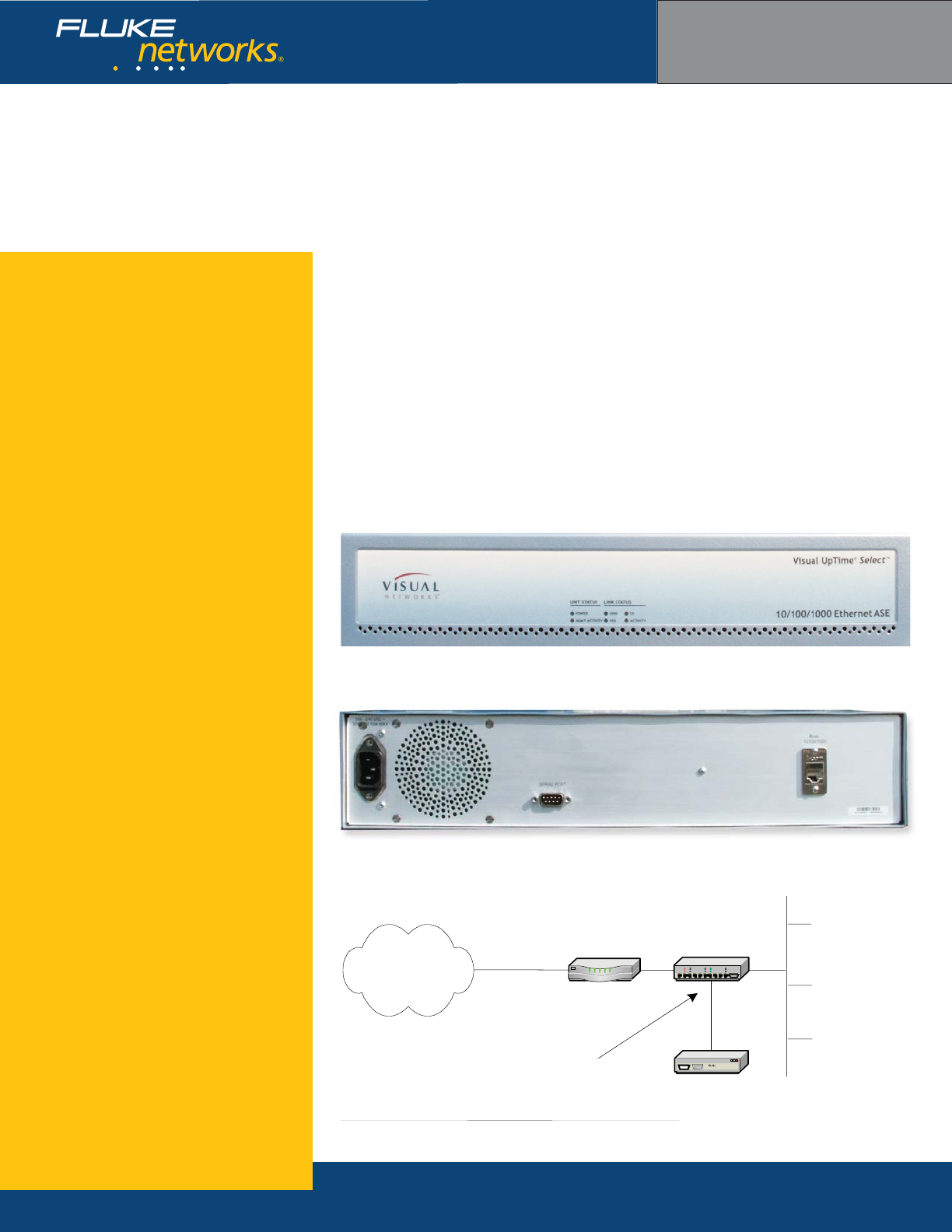
The Visual UpTime® Select™ 10/100/1000 Ethernet
ASE enhances the analysis functionality of Visual
UpTime Select for Ethernet networks. The ASE
provides up to 500 Mbps of detailed network traffi c
analysis and management, while maintaining full wire
speed pass-through of all traffi c. It supports both IP
Transport and LAN Visibility software
Designed for business class DSL and cable, the
10/100/1000 Ethernet ASE has a wide variety of
deployment options. The IP Transport Ethernet ASE is
deployed off a LAN switch SPAN port (see fi gure).
The LAN Visibility Ethernet ASE is deployed on the
LAN. The ASE collects and displays application fl ow
traffi c on the LAN between clients and application
server. In contrast, the IP Transport ASE is designed
to display only traffi c to or from the WAN, and ignore
local traffi c (such as between a client and an Inter-
net or application server).
Ethernet inline probe model 807-0220 front view
Visual UpTime Select
ASE model 807-0220
Ethernet inline probe model model 807-0220 rear view
Ethernet probe model 807-0220 deployed on a LAN switch SPAN port
LANEthernet ASE
Customer
Edge Router
Wide Area
Network
LAN Switch
SPAN port
NETWORKSUPERVISION
Fluke Networks
P.O. Box 777, Everett, WA USA 98206-0777
Fluke Networks operates in more than 50 countries
worldwide. To fi nd your local offi ce contact details, go to
www.fl ukenetworks.com/contact.
©2006 Fluke Corporation. All rights reserved.
Printed in U.S.A. 2/2006 2643429 D-ENG-N Rev A
What are ASEs?
ASEs (Analysis Service Elements) are data
collection and network performance monitor-
ing hardware devices placed on a wide area
network (WAN) or Local Area Network (LAN)
as part of the Visual UpTime Select system,
which offers in-depth, real-time, and historical
visibility into the performance of your
applications infrastructure. In the system,
data gathered by ASEs is stored in the Visual
UpTime Select server and displayed and ana-
lyzed from the Visual UpTime Select Web client.
As a service level management tool, ASEs
indicate when services are being met, provide
warnings when services start to degrade, and
send alerts when services are not met.
Hardware Warranties
Enhanced Gold, Bronze, and International
Gold ASE hardware warranty service programs
are available to help you maximize your
investment in Visual UpTime Select. For more
detailed warranty information, visit:
www.fl ukenetworks.com/visualcustomercare
Ordering Information
For more details, please contact your Visual
UpTime Select authorized reseller or
Fluke Networks Sales at (800) 240-4010
or (301) 296-2300.
Ethernt inline probe ASE specifcations
General Dimensions 17.3” (43.9 cm) x 12” (30.5 cm) x 3.5” (8.9 cm)
Weight 10.45 lbs.
Maximum Data Rate 500 Mbps
Environment Operating Temperature 0o to +40oC (+32o to +104o F)
Storage Temperature -20o to +55oC (-4o to +131o×F)
Clearance Requirement Minimum of 3” (7.62 cm) space on sides.
Power Requirements Input 100 to 240 VAC
Frequency 50/60 Hz
Input Current Rating 0.5 amps
LAN and WAN
Ethernet Interface
Bit Rate 10/100/1000 Mbps
Connector 8-pin modular jack: RJ-45
Serial Port Interface Baud Rate 19200 or 9600 bps
Parity 8 data bits, no parity
Stop Bit 1 stop bit
Electrical Format EIA RS-232, DTE
Connector 9-pin D, male per EIA-574
Technical Data
HSSI i nline probe ASE
With LinkSafe capabilities
Key features
Inband management capabilities
LinkSafe technology
Power loss detection
Multi-Protocol or IP Transport software
Service Level Agreement (SLA) metrics
Application analysis capability
LMI spoofi ng
LAN management port
Realtime events
•
•
•
•
•
•
•
•
•
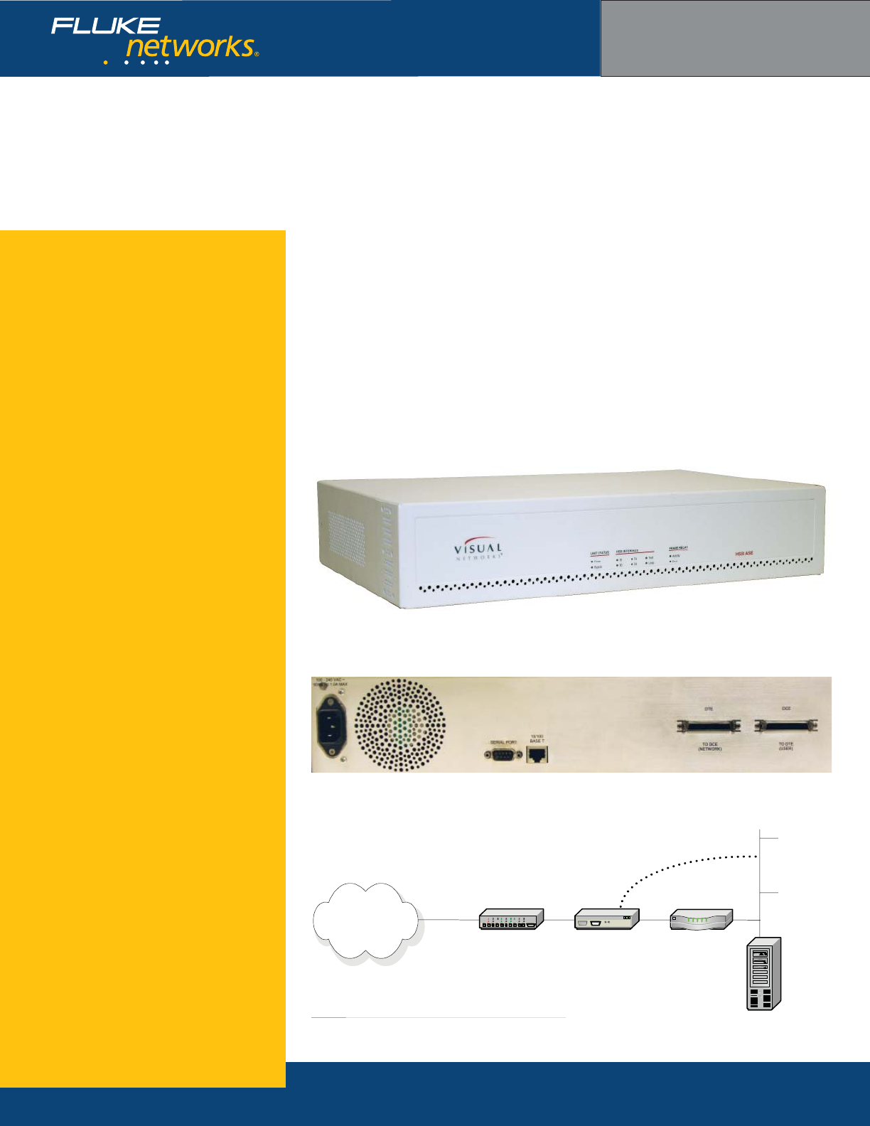
The Visual UpTime® Select™ HSSI LinkSafe™ inline
probe ASE is deployed inline on a High Speed Serial
Interface (HSSI) access line, typically between a
CSU/DSU and customer edge router. It is capable of
monitoring traffi c fl owing through a bi-directional
HSSI connection at data rates up to 44.7 Mbps.
The HSSI ASE supports Multi-Protocol software for
deployment in standard frame relay or HDLC networks
and IP Transport software for deployment in frame
relay or HDLC-based networks that use IP switching.
The ASE also includes LinkSafe technology to protect
circuit integrity in case of an ASE outage, as well as
power failure notifi cation.
The HSSI ASE has two HSSI interfaces, Data Ter-
minal Equipment (DTE) for monitoring traffi c to the
network and Data Communication Equipment (DCE)
for monitoring traffi c from the network. Because of
its high speed capabilities, a HSSI ASE can support
data passed through the CSU/DSU from NxT1
and DS3 lines.
HSSI inline probe model model 807-0106 rear view
HSSI inline probe model 807-0106 front view
HSSI inline probe model 807-0106 position on network
Visual UpTime Select
ASE model 807-0106
Access Line
LAN
Inline ASE
Optional LAN
Connection
CPE Router
Visual UpTime
Select Server
WAN
CSU/DSU

NETWORKSUPERVISION
Fluke Networks
P.O. Box 777, Everett, WA USA 98206-0777
Fluke Networks operates in more than 50 countries
worldwide. To fi nd your local offi ce contact details, go to
www.fl ukenetworks.com/contact.
©2006 Fluke Corporation. All rights reserved.
Printed in U.S.A. 2/2006 2643476 D-ENG-N Rev A
What are ASEs?
ASEs (Analysis Service Elements) are data
collection and network performance monitor-
ing hardware devices placed on a wide area
network (WAN) or Local Area Network (LAN)
as part of the Visual UpTime Select system,
which offers in-depth, real-time, and historical
visibility into the performance of your
applications infrastructure. In the system,
data gathered by ASEs is stored in the Visual
UpTime Select server and displayed and ana-
lyzed from the Visual UpTime Select Web client.
As a service level management tool, ASEs
indicate when services are being met, provide
warnings when services start to degrade, and
send alerts when services are not met.
Hardware Warranties
Enhanced Gold, Bronze, and International
Gold ASE hardware warranty service programs
are available to help you maximize your
investment in Visual UpTime Select. For more
detailed warranty information, visit:
www.fl ukenetworks.com/visualcustomercare
Ordering Information
For more details, please contact your Visual
UpTime Select authorized reseller or
Fluke Networks Sales at (800) 240-4010
or (301) 296-2300.
HSSI inline probe ASE specifcations
General Dimensions 17.3” (43.9 cm) x 12” (30.5 cm) x 3.5” (8.9 cm)
Weight 10.45 lbs.
Data Rate 0 to 44.736 Mbps synchronous
Timing Mode RD: Always synchronous with SCR
SD: Synchronous with SCT or SCTE
Environment Operating Temperature 0o to +40oC (+32o to +104o F)
Storage Temperature -20o to +55oC (-4o to +131o×F)
Clearance Requirement Minimum of 3” (7.62 cm) space on sides.
Operating and Storage
Humidity
10% to 80%, noncondensing
Power Requirements Input 100 to 240 VAC
Frequency 50/60 Hz
Input Current Rating 1 amp
HSSI Interface Confi guration Two HSSI interfaces: one DTE and one DCE for
monitoring to-network and from-network traffi c.
Serial Port Interface Baud Rate 19200 or 9600 bps
Parity 8 data bits, no parity
Stop Bit 1 stop bit
Electrical Format EIA RS-232, DTE
Connector 9-pin D, male per EIA-574
Ethernet 10/100BaseT
Interface
Bite Rate 10 or 100 Mbps
Connector 8-pin modular jack: RJ-48
Technical Data
V.35 i nline probe ASE
With LinkSafe capabilities
Key features
Inband management capabilities
LinkSafe technology
Multi-Protocol or IP Transport software
Service Level Agreement (SLA) metrics
Voice over IP (VoIP) analysis capability
Application analysis capability
LMI spoofi ng
LAN management port
Power loss detection
Realtime events
•
•
•
•
•
•
•
•
•
•
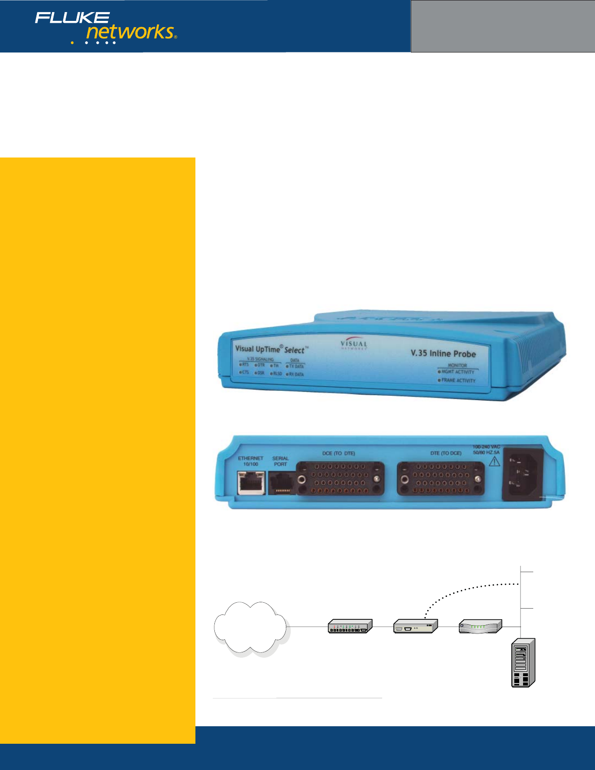
The Visual UpTime® Select™ V.35 LinkSafe™ inline
probe ASE is deployed inline on a T1 access line,
typically between a CSU/DSU and customer premises
equipment. This ASE supports Multi-Protocol software
for deployment in standard frame relay or HDLC
networks and IP Transport software for deployment
in frame relay or HDLC-based networks that use IP
switching.
The V.35 inline probe ASE supports V.35 connectiv-
ity through a V.35 Data Terminal Equipment (DTE)
interface on the network side and Data Communica-
tions Equipment (DCE) interface on the user side.
The ASE operates at data rates up to 2.048 Mbps,
deriving timing from the network-side and sourcing
timing on the user side. It also includes LinkSafe
technology to protect circuit integrity in case of an
ASE outage, as well as power failure notifi cation.
V.35 inline probe model model 807-0104 rear view
V.35 inline probe model 807-0104 front view
V.35 inline probe model 807-0104 position on network
Visual UpTime Select
ASE model 807-0104
Access Line
LAN
Inline ASE
Optional LAN
Connection
CPE Router
Visual UpTime
Select Server
WAN
CSU/DSU
NETWORKSUPERVISION
Fluke Networks
P.O. Box 777, Everett, WA USA 98206-0777
Fluke Networks operates in more than 50 countries
worldwide. To fi nd your local offi ce contact details, go to
www.fl ukenetworks.com/contact.
©2006 Fluke Corporation. All rights reserved.
Printed in U.S.A. 2/2006 2643465 D-ENG-N Rev A
What are ASEs?
ASEs (Analysis Service Elements) are data
collection and network performance monitor-
ing hardware devices placed on a wide area
network (WAN) or Local Area Network (LAN)
as part of the Visual UpTime Select system,
which offers in-depth, real-time, and historical
visibility into the performance of your
applications infrastructure. In the system,
data gathered by ASEs is stored in the Visual
UpTime Select server and displayed and ana-
lyzed from the Visual UpTime Select Web client.
As a service level management tool, ASEs
indicate when services are being met, provide
warnings when services start to degrade, and
send alerts when services are not met.
Hardware Warranties
Enhanced Gold, Bronze, and International
Gold ASE hardware warranty service programs
are available to help you maximize your
investment in Visual UpTime Select. For more
detailed warranty information, visit:
www.fl ukenetworks.com/visualcustomercare
Ordering Information
For more details, please contact your Visual
UpTime Select authorized reseller or
Fluke Networks Sales at (800) 240-4010
or (301) 296-2300.
V.35 inline probe ASE specifcations
General Dimensions 8.16” (20.7 cm) x 9.0” (22.8 cm) x 1.62”(4.1 cm)
Plastic case with internal power supply
Weight 2.10 lbs.
Data Rate 0 to 2.048 Mbps synchronous
Timing Mode RD: Always synchronous with SCR
SD: Synchronous with SCT or SCTE
Environment Operating Temperature 0o to +40oC (+32o to +104o F)
Storage Temperature -20o to +55oC (-4o to +131o×F)
Clearance Requirement Minimum of 3” (7.62 cm) space on sides.
Operating and Storage
Humidity
10% to 80%, noncondensing
Power Requirements Input 100 to 240 VAC
Frequency 50/60 Hz
Input Current Rating 0.5 amps
V.35 User Interface
(DCE)
Confi guration DCE for interfacing with DTE
Data and Clock Leads ITU-T V.35
Signaling Leads EIA RS-232 (ITU-T V.28)
Connector Female 34-pin V.35 connector
Signaling RTS, DTR
V.35 Network
Interface
(DTE)
Confi guration DTE for interfacing with DCE
Data and Clock Leads ITU-T V.35
Signaling Leads EIA RS-232 (ITU-T V.28)
Connector Female 34-pin V.35 connector
Signaling CTS, RLSD, DSR
Serial Port Interface Baud Rate 19200 or 9600 bps
Parity 8 data bits, no parity
Stop Bit 1 stop bit
Electrical Format EIA RS-232, DTE
Connector RJ-45
Ethernet 10/100BaseT
Interface
Bite Rate 10 or 100 Mbps
Connector 8-pin modular jack: RJ-48
Technical Data
X.21 i nline probe ASE
With LinkSafe capabilities
Key features
Inband management capabilities
LinkSafe technology
Multi-Protocol or IP Transport software
Service Level Agreement (SLA) metrics
Voice over IP (VoIP) analysis capability
Application analysis capability
LMI spoofi ng
LAN management port
Power loss detection
Realtime events
•
•
•
•
•
•
•
•
•
•
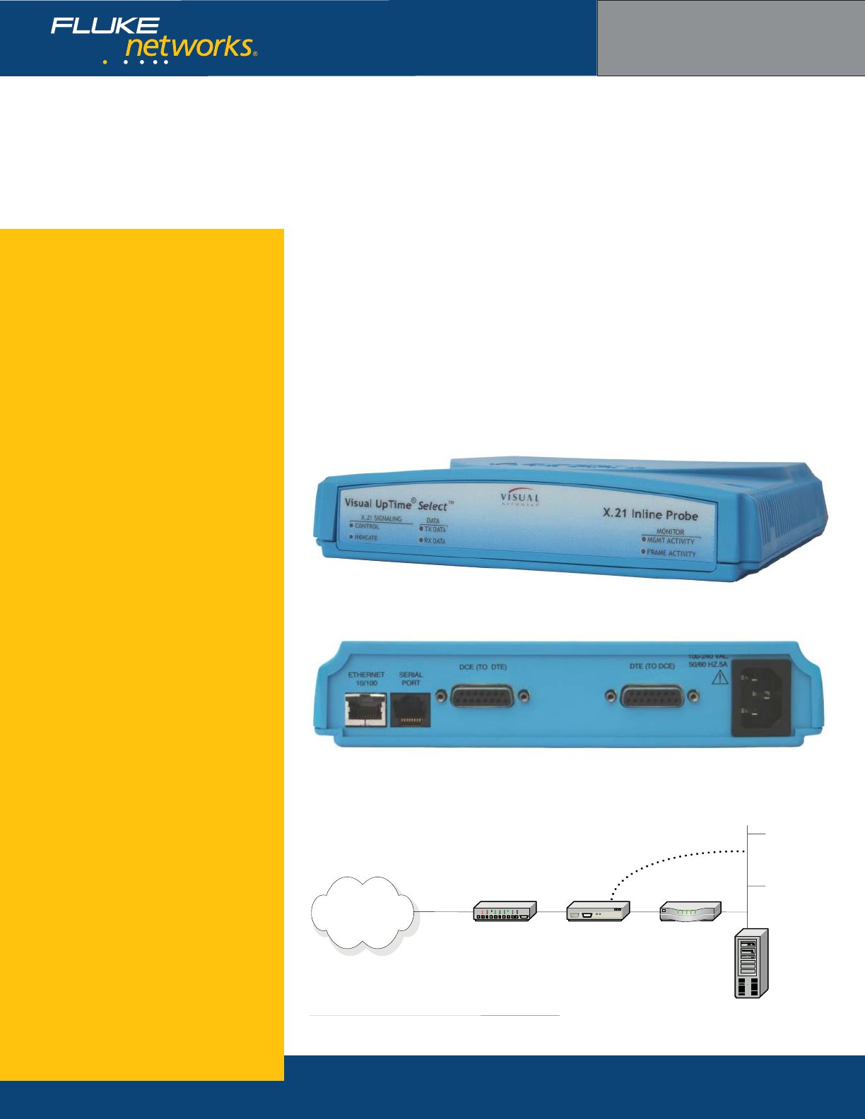
The Visual UpTime® Select™ X.21 LinkSafe™ inline
probe ASE is deployed inline on an access line, typical-
ly between a CSU/DSU and customer premises equip-
ment (CPE). It supports Multi-Protocol software for
deployment in standard frame relay or HDLC networks
and IP Transport software for deployment in frame
relay or HDLC-based networks that use IP switching.
The ASE supports X.21 connectivity through a X.21
Data Terminal Equipment (DTE) interface on the
network side and Data Communications Equipment
(DCE) interface on the user side.
The ASE operates at data rates up to 2.048 Mbps,
deriving timing from the network-side and sourcing
timing on the user side. It also includes LinkSafe
technology to protect circuit integrity in case of an
ASE outage, as well as power failure notifi cation.
X.21 inline probe model model 807-0105 rear view
X.21 inline probe model 807-0105 front view
X.21 inline probe model 807-0105 position on network
Visual UpTime Select
ASE model 807-0105
Access Line
LAN
Inline ASE
Optional LAN
Connection
CPE Router
Visual UpTime
Select Server
WAN
CSU/DSU
NETWORKSUPERVISION
Fluke Networks
P.O. Box 777, Everett, WA USA 98206-0777
Fluke Networks operates in more than 50 countries
worldwide. To fi nd your local offi ce contact details, go to
www.fl ukenetworks.com/contact.
©2006 Fluke Corporation. All rights reserved.
Printed in U.S.A. 2/2006 2643152 D-ENG-N Rev A
What are ASEs?
ASEs (Analysis Service Elements) are data
collection and network performance monitor-
ing hardware devices placed on a wide area
network (WAN) or Local Area Network (LAN)
as part of the Visual UpTime Select system,
which offers in-depth, real-time, and historical
visibility into the performance of your
applications infrastructure. In the system,
data gathered by ASEs is stored in the Visual
UpTime Select server and displayed and ana-
lyzed from the Visual UpTime Select Web client.
As a service level management tool, ASEs
indicate when services are being met, provide
warnings when services start to degrade, and
send alerts when services are not met.
Hardware Warranties
Enhanced Gold, Bronze, and International
Gold ASE hardware warranty service programs
are available to help you maximize your
investment in Visual UpTime Select. For more
detailed warranty information, visit:
www.fl ukenetworks.com/visualcustomercare
Ordering Information
For more details, please contact your Visual
UpTime Select authorized reseller or
Fluke Networks Sales at (800) 240-4010
or (301) 296-2300.
X.21 inline probe ASE specifcations
General Dimensions 8.16” (20.7 cm) x 9.0” (22.8 cm) x 1.62”(4.1 cm)
Plastic case with internal power supply
Weight 2.10 lbs.
Data Rate 0 to 2.048 Mbps synchronous
Timing Mode RD: Always synchronous with SCR
SD: Synchronous with SCT or SCTE
Environment Operating Temperature 0o to +40oC (+32o to +104o F)
Storage Temperature -20o to +55oC (-4o to +131o×F)
Clearance Requirement Minimum of 3” (7.62 cm) space on sides.
Operating and Storage
Humidity
10% to 80%, noncondensing
Power Requirements Input 100 to 240 VAC
Frequency 50/60 Hz
Input Current Rating 0.5 amps
X.21 User Interface
(DCE)
Confi guration DCE for interfacing with DTE
Data and Clock Leads ITU-CCITT X.21
Signaling Leads ITU-CCITT X.21
Connector Female 15-pin X.21 connector
Signaling Indicate: Clear to Send control signal to the user
interface. Received and terminated by the ASE.
X.21 Network
Interface (DTE)
Confi guration DTE for interfacing with DCE
Data and Clock Leads ITU-CCITT X.21
Signaling Leads ITU-CCITT X.21
Connector Female 15-pin X.21 connector
Signaling Control: Request to Send control signal from the
user interface. On while power is applied by the
ASE.
Serial Port Interface Baud Rate 19200 or 9600 bps
Parity 8 data bits, no parity
Stop Bit 1 stop bit
Electrical Format EIA RS-232, DTE
Connector RJ-45
Ethernet 10/100BaseT
Interface
Bite Rate 10 or 100 Mbps
Connector 8-pin modular jack: RJ-48

Technical Data
DS3 i nline probe ASE
With LinkSafe capabilities
Key features
Inband management capabilities
LinkSafe technology
Multi-Protocol or IP Transport software
Service Level Agreement (SLA) metrics
Application analysis capability
LAN management port
Realtime events
•
•
•
•
•
•
•
The Visual UpTime® Select™ DS3 LinkSafe™ inline
probe ASE complies with Class A standards for
countries using DS3 ATM lines (U.S. and Canada) and
supports digital transmission at the DS3 rate of 44
Mbps. This ASE supports Multi-Protocol software for
deployment in standard ATM networks and IP Trans-
port software for deployment in ATM-based networks
that use IP switching. The ASE also includes LinkSafe
technology to protect circuit integrity in case of an
ASE outage, as well as power failure notifi cation.
The DS3 inline probe ASE is designed for deploy-
ment at the network demarcation point between a
subscriber’s CPE and the WAN. It can be deployed in
ATM and mixed frame relay-ATM environments. The
fi gure below shows the ASE positioned at the edge of
an inter-worked frame relay-to-ATM network, allowing
for SLA messaging between a frame relay DLCI and an
ATM VPI/VCI.
DS3 inline probe model 200 rear view
DS3 inline probe model 200 front view
DS3 inline probe model 200 on ATM/Frame network
Visual UpTime Select
ASE model 807-0200
Branch ASEs
T1
Frame
Network ATM
Network
Frame to ATM
Interworking
Visual
UpTime
Select
server
LAN
ATM ASE CPE
Router

NETWORKSUPERVISION
Fluke Networks
P.O. Box 777, Everett, WA USA 98206-0777
Fluke Networks operates in more than 50 countries
worldwide. To fi nd your local offi ce contact details, go to
www.fl ukenetworks.com/contact.
©2006 Fluke Corporation. All rights reserved.
Printed in U.S.A. 2/2006 2643490 D-ENG-N Rev A
What are ASEs?
ASEs (Analysis Service Elements) are data
collection and network performance monitor-
ing hardware devices placed on a wide area
network (WAN) or Local Area Network (LAN)
as part of the Visual UpTime Select system,
which offers in-depth, real-time, and historical
visibility into the performance of your
applications infrastructure. In the system,
data gathered by ASEs is stored in the Visual
UpTime Select server and displayed and ana-
lyzed from the Visual UpTime Select Web client.
As a service level management tool, ASEs
indicate when services are being met, provide
warnings when services start to degrade, and
send alerts when services are not met.
Hardware Warranties
Enhanced Gold, Bronze, and International
Gold ASE hardware warranty service programs
are available to help you maximize your
investment in Visual UpTime Select. For more
detailed warranty information, visit:
www.fl ukenetworks.com/visualcustomercare
Ordering Information
For more details, please contact your Visual
UpTime Select authorized reseller or
Fluke Networks Sales at (800) 240-4010
or (301) 296-2300.
DS3 inline probe ASE specifcations
General Dimensions 1 EIA unit (1.75”) high x 19” wide rack-mountable
chassis
Weight 10 lbs.
Data Rate to 45 Mbps synchronous
Timing Mode Derived externally from the network.
Environment Operating Temperature 0o to +40oC (+32o to +104oF)
Storage Temperature -20o to +55oC (-4o to +131oF)
Clearance Requirement Minimum of 3” (7.62 cm) space on sides.
Operating/Storage Humidity 10% to 90% non-condensing
Power Requirements Input 100 to 240 VAC
Frequency 50/60 Hz
Input Current Rating 0.5 amps
Network Interface Line Rate 44.736 Mbps
Cell Delineation HEC or PLCP
Cell Scrambler Enable or Disable
Line Build Out Long = more than 225 feet. Short = 225 feet or less.
Connector 4 BNC (75 ohm), Network Tx and Rx, CPE Tx and Rx
Serial Port Interface Baud Rate 57600, 19200, or 9600 bps
Parity 8 data bits, no parity
Stop Bit 1 stop bit
Electrical Format EIA RS-232, DTE
Connector 9-pin D, male per EIA-574
Ethernet 10/100BaseT
Interface
Bite Rate 10 or 100 Mbps
Connector 8-pin modular jack: RJ-48

Technical Data
E3 i nline probe ASE
With LinkSafe capabilities
Key features
Inband management capabilities
LinkSafe technology
Multi-Protocol or IP Transport software
Service Level Agreement (SLA) metrics
Application analysis capability
LAN management port
Realtime events
•
•
•
•
•
•
•
The Visual UpTime® Select™ E3 LinkSafe™ inline
probe ASE complies with Class A standards for
countries using E3 ATM lines and supports digital
transmission at the E3 rate of 34 Mbps. This ASE
supports Multi-Protocol software for deployment in
standard ATM networks and IP Transport software
for deployment in ATM-based networks that use IP
switching. The ASE also includes LinkSafe technology
to protect circuit integrity in case of an ASE outage,
as well as power failure notifi cation.
The E3 inline probe ASE is designed for deploy-
ment at the network demarcation point between a
subscriber’s CPE and the WAN. It can be deployed in
ATM and mixed frame relay-ATM environments. The
fi gure below shows the ASE positioned at the edge of
an inter-worked frame relay-to-ATM network, allowing
for SLA messaging between a frame relay DLCI and an
ATM VPI/VCI.
E3 inline probe model 201 rear view
E3 inline probe model 201 on ATM/Frame network
Visual UpTime Select
ASE model 807-0201
E3 inline probe model 201 front view
Branch ASEs
T1
Frame
Network ATM
Network
Frame to ATM
Interworking
Visual
UpTime
Select
server
LAN
ATM ASE CPE
Router
NETWORKSUPERVISION
Fluke Networks
P.O. Box 777, Everett, WA USA 98206-0777
Fluke Networks operates in more than 50 countries
worldwide. To fi nd your local offi ce contact details, go to
www.fl ukenetworks.com/contact.
©2006 Fluke Corporation. All rights reserved.
Printed in U.S.A. 2/2006 2643483 D-ENG-N Rev A
What are ASEs?
ASEs (Analysis Service Elements) are data
collection and network performance monitor-
ing hardware devices placed on a wide area
network (WAN) or Local Area Network (LAN)
as part of the Visual UpTime Select system,
which offers in-depth, real-time, and historical
visibility into the performance of your
applications infrastructure. In the system,
data gathered by ASEs is stored in the Visual
UpTime Select server and displayed and ana-
lyzed from the Visual UpTime Select Web client.
As a service level management tool, ASEs
indicate when services are being met, provide
warnings when services start to degrade, and
send alerts when services are not met.
Hardware Warranties
Enhanced Gold, Bronze, and International
Gold ASE hardware warranty service programs
are available to help you maximize your
investment in Visual UpTime Select. For more
detailed warranty information, visit:
www.fl ukenetworks.com/visualcustomercare
Ordering Information
For more details, please contact your Visual
UpTime Select authorized reseller or
Fluke Networks Sales at (800) 240-4010
or (301) 296-2300.
E3 inline probe ASE specifcations
General Dimensions 1 EIA unit (1.75”) high x 19” wide rack-mountable
chassis
Weight 10 lbs.
Data Rate to 34 Mbps synchronous
Timing Mode Derived externally from the network.
Environment Operating Temperature 0o to +40oC (+32o to +104oF)
Storage Temperature -20o to +55oC (-4o to +131oF)
Clearance Requirement Minimum of 3” (7.62 cm) space on sides.
Operating/Storage Humidity 10% to 90% non-condensing
Power Requirements Input 100 to 240 VAC
Frequency 50/60 Hz
Input Current Rating 0.5 amps
Network Interface Line Rate 34.368 Mbps
Cell Delineation HEC or PLCP
Cell Scrambler Enable or Disable
Connector 4 BNC (75 ohm), Network Tx and Rx, CPE Tx and Rx
Serial Port Interface Baud Rate 57600, 19200, or 9600 bps
Parity 8 data bits, no parity
Stop Bit 1 stop bit
Electrical Format EIA RS-232, DTE
Connector 9-pin D, male per EIA-574
Ethernet 10/100BaseT
Interface
Bite Rate 10 or 100 Mbps
Connector 8-pin modular jack: RJ-48
Technical Data
OC-3c/STM-1 i nline probe ASE
Single mode with LinkSafe capabilities
Key features
Inband management capabilities
LinkSafe technology
Multi-Protocol or IP Transport software
Service Level Agreement (SLA) metrics
Application analysis capability
LAN management port
Realtime events
•
•
•
•
•
•
•
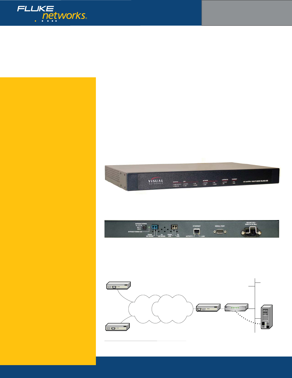
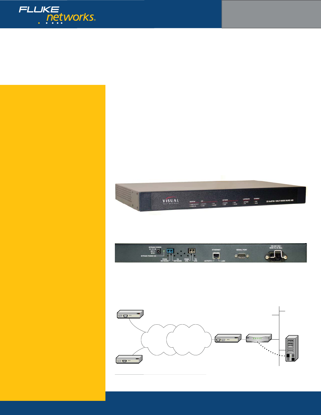
The Visual UpTime® Select™ OC-3c/STM-1 LinkSafe™
inline probe ASE supports single mode ATM OC-3c
physical lines, with SONET and SDH standards, at
speeds up to 155 Mbps. This ASE supports Multi-Proto-
col software for deployment in standard ATM networks
and IP Transport software for deployment in ATM-based
networks that use IP switching. The ASE also includes
LinkSafe technology to protect circuit integrity in case
of an ASE outage, as well as power failure notifi cation.
The OC-3c/STM-1 inline probe ASE is designed
for deployment at the network demarcation point
between a subscriber’s CPE and the WAN. It can be
deployed in ATM and mixed frame relay-ATM environ-
ments. The fi gure below shows the ASE positioned
at the edge of an inter-worked frame relay-to-ATM
network, allowing for SLA messaging between a frame
relay DLCI and an ATM VPI/VCI.
OC-3c inline probe model 202 rear view
OC-3c inline probe model 202 front view
OC-3c inline probe model 202 on ATM/Frame network
Visual UpTime Select
ASE model 807-0202
Branch ASEs
T1
Frame
Network ATM
Network
Frame to ATM
Interworking
Visual
UpTime
Select
server
LAN
OC-3c
ATM ASE CPE
Router
NETWORKSUPERVISION
Fluke Networks
P.O. Box 777, Everett, WA USA 98206-0777
Fluke Networks operates in more than 50 countries
worldwide. To fi nd your local offi ce contact details, go to
www.fl ukenetworks.com/contact.
©2006 Fluke Corporation. All rights reserved.
Printed in U.S.A. 2/2006 2643526 D-ENG-N Rev A
What are ASEs?
ASEs (Analysis Service Elements) are data
collection and network performance monitor-
ing hardware devices placed on a wide area
network (WAN) or Local Area Network (LAN)
as part of the Visual UpTime Select system,
which offers in-depth, real-time, and historical
visibility into the performance of your
applications infrastructure. In the system,
data gathered by ASEs is stored in the Visual
UpTime Select server and displayed and ana-
lyzed from the Visual UpTime Select Web client.
As a service level management tool, ASEs
indicate when services are being met, provide
warnings when services start to degrade, and
send alerts when services are not met.
Hardware Warranties
Enhanced Gold, Bronze, and International
Gold ASE hardware warranty service programs
are available to help you maximize your
investment in Visual UpTime Select. For more
detailed warranty information, visit:
www.fl ukenetworks.com/visualcustomercare
Ordering Information
For more details, please contact your Visual
UpTime Select authorized reseller or
Fluke Networks Sales at (800) 240-4010
or (301) 296-2300.
OC-3c inline probe ASE specifcations
General Dimensions 1 EIA unit (1.75”) high x 19” wide rack-mountable
chassis
Weight 10 lbs.
Data Rate to 155 Mbps synchronous
Timing Mode Derived externally from the network.
Environment Operating Temperature 0o to +40oC (+32o to +104oF)
Storage Temperature -20o to +55oC (-4o to +131oF)
Clearance Requirement Minimum of 3” (7.62 cm) space on sides.
Operating/Storage Humidity 10% to 90% non-condensing
Power Requirements Input 100 to 240 VAC
Frequency 50/60 Hz
Input Current Rating 0.5 amps
Bypass 5 volt 1 amp DC
Network Interface Line Rate 155.52 Mbps
Line Mode SONET or SDH
Cell Delineation HEC
Cell Scrambler Enable or Disable
Connectors 2 Sff Duplex-LC, Network Tx and Rx, CPE Tx and Rx
Wavelength 1274 nm/1356 nm
Tx Average Output Power -11dBm (typical) Measured with single mode cable
Rx Sensitivity -33dBm (typical)
Serial Port Interface Baud Rate 57600, 19200, or 9600 bps
Parity 8 data bits, no parity
Stop Bit 1 stop bit
Electrical Format EIA RS-232, DTE
Connector 9-pin D, male per EIA-574
Ethernet 10/100BaseT
Interface
Bite Rate 10 or 100 Mbps
Connector 8-pin modular jack: RJ-48
Compliant with Bellcore GR-253 CORE and ITE G.957 standards
Technical Data
OC-3c/STM-1 i nline probe ASE
Multimode with LinkSafe capabilities
Key features
Inband management capabilities
LinkSafe technology
Multi-Protocol or IP Transport software
Service Level Agreement (SLA) metrics
Application analysis capability
LAN management port
Realtime events
•
•
•
•
•
•
•
The Visual UpTime® Select™ OC-3c/STM-1 LinkSafe™
inline probe ASE supports multimode ATM OC-3c
physical lines, with SONET and SDH standards, at
speeds up to 155 Mbps. This ASE supports Multi-
Protocol software for deployment in standard ATM
networks and IP Transport software for deployment in
ATM-based networks that use IP switching. The ASE
also includes LinkSafe technology to protect circuit
integrity in case of an ASE outage, as well as power
failure notifi cation.
The OC-3c/STM-1 inline probe ASE is designed
for deployment at the network demarcation point
between a subscriber’s CPE and the WAN. It can be
deployed in ATM and mixed frame relay-ATM environ-
ments. The fi gure below shows the ASE positioned
at the edge of an inter-worked frame relay-to-ATM
network, allowing for SLA messaging between a frame
relay DLCI and an ATM VPI/VCI.
OC-3c inline probe model 203 rear view
OC-3c inline probe model 203 front view
OC-3c inline probe model 203 on ATM/Frame network
Visual UpTime Select
ASE model 807-0203
Branch ASEs
T1
Frame
Network ATM
Network
Frame to ATM
Interworking
Visual
UpTime
Select
server
LAN
OC-3c
ATM ASE CPE
Router

NETWORKSUPERVISION
Fluke Networks
P.O. Box 777, Everett, WA USA 98206-0777
Fluke Networks operates in more than 50 countries
worldwide. To fi nd your local offi ce contact details, go to
www.fl ukenetworks.com/contact.
©2006 Fluke Corporation. All rights reserved.
Printed in U.S.A. 2/2006 2643515 D-ENG-N Rev A
What are ASEs?
ASEs (Analysis Service Elements) are data
collection and network performance monitor-
ing hardware devices placed on a wide area
network (WAN) or Local Area Network (LAN)
as part of the Visual UpTime Select system,
which offers in-depth, real-time, and historical
visibility into the performance of your
applications infrastructure. In the system,
data gathered by ASEs is stored in the Visual
UpTime Select server and displayed and ana-
lyzed from the Visual UpTime Select Web client.
As a service level management tool, ASEs
indicate when services are being met, provide
warnings when services start to degrade, and
send alerts when services are not met.
Hardware Warranties
Enhanced Gold, Bronze, and International
Gold ASE hardware warranty service programs
are available to help you maximize your
investment in Visual UpTime Select. For more
detailed warranty information, visit:
www.fl ukenetworks.com/visualcustomercare
Ordering Information
For more details, please contact your Visual
UpTime Select authorized reseller or
Fluke Networks Sales at (800) 240-4010
or (301) 296-2300.
OC-3c inline probe ASE specifcations
General Dimensions 1 EIA unit (1.75”) high x 19” wide rack-mountable
chassis
Weight 10 lbs.
Data Rate to 155 Mbps synchronous
Timing Mode Derived externally from the network.
Environment Operating Temperature 0o to +40oC (+32o to +104oF)
Storage Temperature -20o to +55oC (-4o to +131oF)
Clearance Requirement Minimum of 3” (7.62 cm) space on sides.
Operating/Storage Humidity 10% to 90% non-condensing
Power Requirements Input 100 to 240 VAC
Frequency 50/60 Hz
Input Current Rating 0.5 amps
Bypass 5 volt 1 amp DC
Network Interface Line Rate 155.52 Mbps
Line Mode SONET or SDH
Cell Delineation HEC
Cell Scrambler Enable or Disable
Connectors 2 Sff Duplex-LC, Network Tx and Rx, CPE Tx and Rx
Wavelength 1270 nm/1380 nm
Tx Average Output Power -16dBm (typical) Measured with 62.5µ/120
Multimedia cable
Rx Sensitivity -33dBm (typical)
Serial Port Interface Baud Rate 57600, 19200, or 9600 bps
Parity 8 data bits, no parity
Stop Bit 1 stop bit
Electrical Format EIA RS-232, DTE
Connector 9-pin D, male per EIA-574
Ethernet 10/100BaseT
Interface
Bite Rate 10 or 100 Mbps
Connector 8-pin modular jack: RJ-48
Technical Data
T1 CSU/DSU ASE
With DSX-1, Drop-and-Insert capabilities
Key features
Inband management capabilities
Multi-Protocol or IP Transport software
Service Level Agreement (SLA) metrics
Drop-and-Insert capabilities through
DSX port
Voice over IP (VoIP) analysis capability
Application analysis capability
LMI spoofi ng
LAN management port
Power loss detection
Realtime events
•
•
•
•
•
•
•
•
•
•
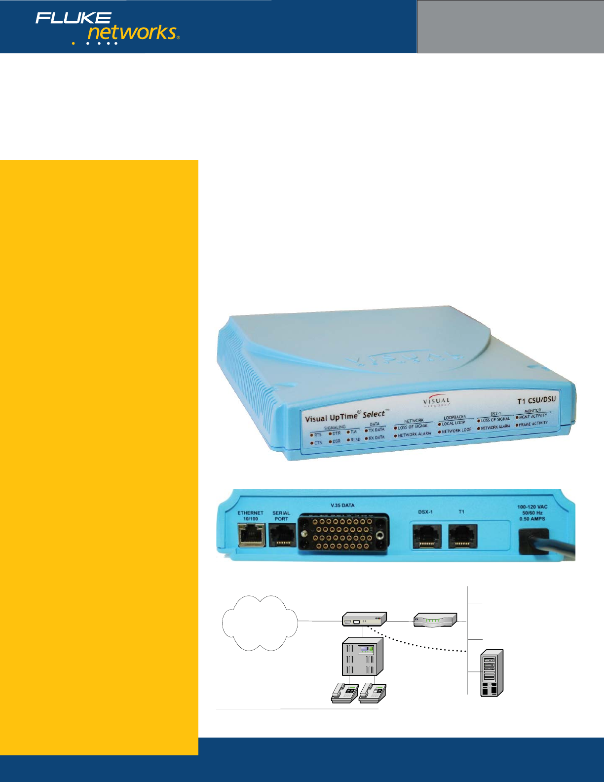
The Visual UpTime® Select™ T1 CSU/DSU ASE is
deployed on a T1 access line at the demarcation point
between the provider network and customer premises.
It supports full and fractional (FT1) T1 networks and
provides connectivity through V.35 and additional
digital cross connect signal (DSX-1) interfaces.
The ASE supports Multi-Protocol software for deploy-
ment in standard frame relay or HDLC networks and
IP Transport software for deployment in frame relay or
HDLC-based networks that use IP switching.
In addition to performing standard CSU/DSU
functions—such as BER tests, loopbacks, and power
failure detection—the ASE is capable of inserting
management traffi c.
The ASE’s “drop-and-insert” feature provides a
secondary DSX-1 port that can connect to a Private
Branch Exchange at a customer’s site. T1 Timeslots
can be segmented for a PBX on the same circuit car-
rying data traffi c (see fi gure).
T1 CSU/DSU model 807-0109 rear view
T1 CSU/DSU model 807-0109 front view
T1 CSU/DSU model 807-0109 position on network
Visual UpTime Select
ASE model 807-0109
T1 Access
Line
Visual
UpTime
Select
Server
V.35
Line
Optional LAN
Connection
CSU/DSU
ASE
Wide Area
Network
PBX
PBX
Tele
p
honeTele
p
hone

NETWORKSUPERVISION
Fluke Networks
P.O. Box 777, Everett, WA USA 98206-0777
Fluke Networks operates in more than 50 countries
worldwide. To fi nd your local offi ce contact details, go to
www.fl ukenetworks.com/contact.
©2006 Fluke Corporation. All rights reserved.
Printed in U.S.A. 2/2006 2643395 D-ENG-N Rev A
What are ASEs?
ASEs (Analysis Service Elements) are data
collection and network performance monitor-
ing hardware devices placed on a wide area
network (WAN) or Local Area Network (LAN)
as part of the Visual UpTime Select system,
which offers in-depth, real-time, and historical
visibility into the performance of your
applications infrastructure. In the system,
data gathered by ASEs is stored in the Visual
UpTime Select server and displayed and ana-
lyzed from the Visual UpTime Select Web client.
As a service level management tool, ASEs
indicate when services are being met, provide
warnings when services start to degrade, and
send alerts when services are not met.
Hardware Warranties
Enhanced Gold, Bronze, and International
Gold ASE hardware warranty service programs
are available to help you maximize your
investment in Visual UpTime Select. For more
detailed warranty information, visit:
www.fl ukenetworks.com/visualcustomercare
Ordering Information
For more details, please contact your Visual
UpTime Select authorized reseller or
Fluke Networks Sales at (800) 240-4010
or (301) 296-2300.
T1 CSU/DSU ASE specifcations
General Dimensions 8.16” (20.7 cm) x 9.0” (22.8 cm) x 1.62”(4.1 cm)
Plastic case with internal power supply.
Weight 2.10 lbs.
Data Rate 1.544 Mbps synchronous
Timing Mode Derived externally from the T1 network or DSX-1
interface, or internally from the ASE.
Environment Operating Temperature 0o to +40oC (+32o to +104o F)
Storage Temperature -20o to +55oC (-4o to +131o×F)
Clearance Requirement Minimum of 3” (7.62 cm) space on sides.
Operating and Storage
Humidity
10% to 90%, noncondensing
Power Requirements Input 100 to 120 VAC
Frequency 50/60 Hz
Input Current Rating 0.5 amps
T1 Network Interface Line Rate 1.544 Mbps ±50 bps synchronous
Line Format AMI or B9ZS line coding
Framing ESF or D4 framing formats
ESF FDL ANSI T1.403, AT&T TR54016, Both, or None
Input Signal 0dB to -36dB
Output Signal 0, -7.5dB, -15dB, -22.5dB LBO
Pulse Density AT&T 62411
Connector 8-pin modular jack—USOC: RJ48C
Timing Loop, DSX-1, or Internal
Channel Selection 1 to 24 channels in any combination
Network DTE Interface
(Data Port)
Confi guration DCE for interfacing with DTE
Data and Clock Leads ITU-T V.35
Signaling Leads EIA RS-232 (ITU-T V.28)
Data Rates 56 kbps x N or 64 kbps x N (N = 1 through 24)
HDLC Inversion Selectable V.35 data inversion
Transmit Timing Basis Network selected-source timing
Receive Timing Basis SCT, inverted SCT, SCTE
Receive Line Data Not Valid RLSD, CTS
Connector Female 34-pin V.35 connector
DSX-1 Interface Line Rate 1.544 Mbps ±50 bps
Line Format AMI or B8ZS
Framing ESF or D4 (SF)
Input Signal -1dB to -11dB
Line Equalization 0 ft, 133 ft, 266 ft, 399 ft, 533 ft, 655 ft
Connector RJ-45
Channel Selection 1 to 24 channels in any combination
Serial Port Interface Specifi cations 19200 or 9600 bps baud rate, 8 data bits no parity,
1 stop bit, EIA RS-232 DTE electrical format, RJ-45
connector
Ethernet 10/100BaseT
Interface
Bite Rate 10 or 100 Mbps
Connector 8-pin modular jack: RJ-48
Technical Data
T1 CSU/DSU ASE
Key features
Inband management capabilities
Multi-Protocol or IP Transport software
Service Level Agreement (SLA) metrics
Voice over IP (VoIP) analysis capability
Application analysis capability
LMI spoofi ng
LAN management port
Power loss detection
Realtime events
•
•
•
•
•
•
•
•
•
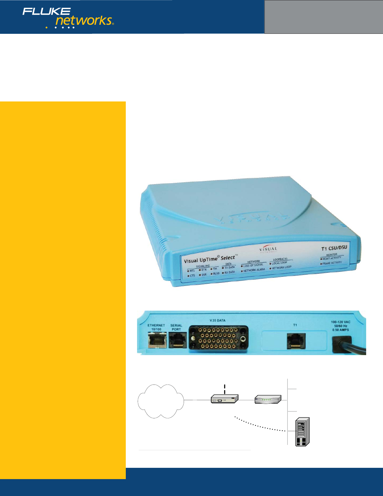
The Visual UpTime® Select™ T1 CSU/DSU ASE is
deployed on a T1 access line at the demarcation point
between the provider network and customer premises.
It supports full and fractional (FT1) T1 networks and
provides connectivity through V.35 interface.
The ASE supports Multi-Protocol software for deploy-
ment in standard frame relay or HDLC networks and
IP Transport software for deployment in frame relay or
HDLC-based networks that use IP switching.
In addition to performing standard CSU/DSU
functions—such as BER tests, loopbacks, and power
failure detection—the ASE is capable of inserting
management traffi c.
T1 CSU/DSU model 807-0110 rear view
T1 CSU/DSU model 807-0110 front view
T1 CSU/DSU model 807-0110 position on network
Visual UpTime Select
ASE model 807-0110
T1 Access
Line
Demarcation Point
Visual
UpTime
Select
Server
V.35
Line
Optional LAN
Connection
Wide Area
Network CSU/DSU
ASE
NETWORKSUPERVISION
Fluke Networks
P.O. Box 777, Everett, WA USA 98206-0777
Fluke Networks operates in more than 50 countries
worldwide. To fi nd your local offi ce contact details, go to
www.fl ukenetworks.com/contact.
©2006 Fluke Corporation. All rights reserved.
Printed in U.S.A. 2/2006 2643388 D-ENG-N Rev A
What are ASEs?
ASEs (Analysis Service Elements) are data
collection and network performance monitor-
ing hardware devices placed on a wide area
network (WAN) or Local Area Network (LAN)
as part of the Visual UpTime Select system,
which offers in-depth, real-time, and historical
visibility into the performance of your
applications infrastructure. In the system,
data gathered by ASEs is stored in the Visual
UpTime Select server and displayed and ana-
lyzed from the Visual UpTime Select Web client.
As a service level management tool, ASEs
indicate when services are being met, provide
warnings when services start to degrade, and
send alerts when services are not met.
Hardware Warranties
Enhanced Gold, Bronze, and International
Gold ASE hardware warranty service programs
are available to help you maximize your
investment in Visual UpTime Select. For more
detailed warranty information, visit:
www.fl ukenetworks.com/visualcustomercare
Ordering Information
For more details, please contact your Visual
UpTime Select authorized reseller or
Fluke Networks Sales at (800) 240-4010
or (301) 296-2300.
T1 CSU/DSU ASE specifcations
General Dimensions 8.16” (20.7 cm) x 9.0” (22.8 cm) x 1.62”(4.1 cm)
Plastic case with internal power supply.
Weight 2.10 lbs.
Data Rate 1.544 Mbps synchronous
Timing Mode Derived externally from the T1 network or DSX-1
interface, or internally from the ASE.
Environment Operating Temperature 0o to +40oC (+32o to +104o F)
Storage Temperature -20o to +55oC (-4o to +131o×F)
Clearance Requirement Minimum of 3” (7.62 cm) space on sides.
Operating and Storage
Humidity
10% to 90%, noncondensing
Power Requirements Input 100 to 120 VAC
Frequency 50/60 Hz
Input Current Rating 0.5 amps
T1 Network Interface Line Rate 1.544 Mbps ±50 bps synchronous
Line Format AMI or B9ZS line coding
Framing ESF or D4 framing formats
ESF FDL ANSI T1.403, AT&T TR54016, Both, or None
Input Signal 0dB to -36dB
Output Signal 0, -7.5dB, -15dB, -22.5dB LBO
Pulse Density AT&T 62411
Connector 8-pin modular jack—USOC: RJ48C
Timing Loop, DSX-1, or Internal
Channel Selection 1 to 24 channels in any combination
Network DTE Interface
(Data Port)
Confi guration DCE for interfacing with DTE
Data and Clock Leads ITU-T V.35
Signaling Leads EIA RS-232 (ITU-T V.28)
Data Rates 56 kbps x N or 64 kbps x N (N = 1 through 24)
HDLC Inversion Selectable V.35 data inversion
Transmit Timing Basis Network selected-source timing
Receive Timing Basis SCT, inverted SCT, SCTE
Receive Line Data Not Valid RLSD, CTS
Connector Female 34-pin V.35 connector
Serial Port Interface Specifi cations 19200 or 9600 bps baud rate, 8 data bits no parity,
1 stop bit, EIA RS-232 DTE electrical format, RJ-45
connector
Ethernet 10/100BaseT
Interface
Bite Rate 10 or 100 Mbps
Connector 8-pin modular jack: RJ-48
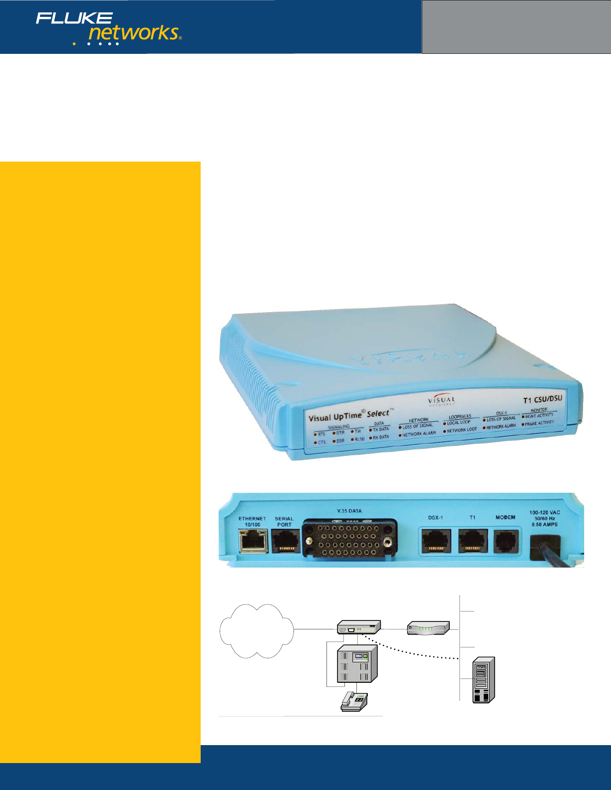
Technical Data
T1 CSU/DSU ASE
With Modem
Key features
Inband management capabilities
Multi-Protocol or IP Transport software
Service Level Agreement (SLA) metrics
Drop-and-Insert capabilities through
DSX port
Internal modem
Voice over IP (VoIP) analysis capability
Application analysis capability
LMI spoofi ng
LAN management port
Power loss detection
Realtime events
•
•
•
•
•
•
•
•
•
•
•
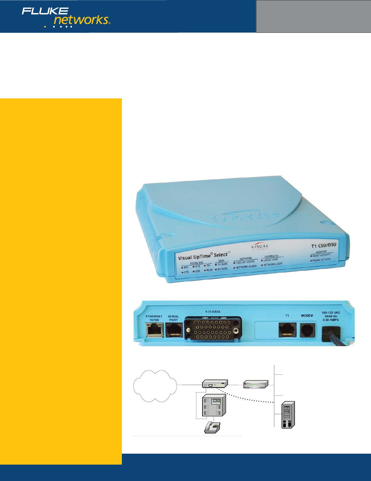
The Visual UpTime® Select™ T1 CSU/DSU ASE is
deployed on a T1 access line at the demarcation point
between the provider network and customer premises.
It supports full and fractional (FT1) T1 networks and
provides connectivity through V.35 interface.
The ASE supports Multi-Protocol software for deploy-
ment in standard frame relay or HDLC networks and
IP Transport software for deployment in networks that
use IP switching.
This ASE features an internal modem that allows
users to establish a telephone connection to either
the ASE’s administrative interface or a pass-through
connection through the serial port.
In addition to performing standard CSU/DSU
functions—such as BER tests, loopbacks, and power
failure detection—the ASE is capable of inserting
management traffi c.
T1 CSU/DSU model 807-0111 rear view
T1 CSU/DSU model 807-0111 front view
T1 CSU/DSU model 807-0111 position on network
Visual UpTime Select
ASE model 807-0111
T1 Access
Line
Visual
UpTime
Select
Server
V.35
Line
Optional LAN
Connection
CSU/DSU
ASE
Wide Area
Network
PBX PBX
Tl h
Modem
Connection
NETWORKSUPERVISION
Fluke Networks
P.O. Box 777, Everett, WA USA 98206-0777
Fluke Networks operates in more than 50 countries
worldwide. To fi nd your local offi ce contact details, go to
www.fl ukenetworks.com/contact.
©2006 Fluke Corporation. All rights reserved.
Printed in U.S.A. 2/2006 2643374 D-ENG-N Rev A
What are ASEs?
ASEs (Analysis Service Elements) are data
collection and network performance monitor-
ing hardware devices placed on a wide area
network (WAN) or Local Area Network (LAN)
as part of the Visual UpTime Select system,
which offers in-depth, real-time, and historical
visibility into the performance of your
applications infrastructure. In the system,
data gathered by ASEs is stored in the Visual
UpTime Select server and displayed and ana-
lyzed from the Visual UpTime Select Web client.
As a service level management tool, ASEs
indicate when services are being met, provide
warnings when services start to degrade, and
send alerts when services are not met.
Hardware Warranties
Enhanced Gold, Bronze, and International
Gold ASE hardware warranty service programs
are available to help you maximize your
investment in Visual UpTime Select. For more
detailed warranty information, visit:
www.fl ukenetworks.com/visualcustomercare
Ordering Information
For more details, please contact your Visual
UpTime Select authorized reseller or
Fluke Networks Sales at (800) 240-4010
or (301) 296-2300.
T1 CSU/DSU ASE specifcations
General Dimensions 8.16” (20.7 cm) x 9.0” (22.8 cm) x 1.62”(4.1 cm)
Plastic case with internal power supply.
Weight 2.10 lbs.
Data Rate 1.544 Mbps synchronous
Timing Mode Derived externally from the T1 network or DSX-1
interface, or internally from the ASE.
Environment Operating Temperature 0o to +40oC (+32o to +104o F)
Storage Temperature -20o to +55oC (-4o to +131o×F)
Clearance Requirement Minimum of 3” (7.62 cm) space on sides.
Operating and Storage
Humidity
10% to 90%, noncondensing
Power Requirements Input 100 to 120 VAC
Frequency 50/60 Hz
Input Current Rating 0.5 amps
T1 Network Interface Line Rate 1.544 Mbps ±50 bps synchronous
Line Format AMI or B9ZS line coding
Framing ESF or D4 framing formats
ESF FDL ANSI T1.403, AT&T TR54016, Both, or None
Input Signal 0dB to -36dB
Output Signal 0, -7.5dB, -15dB, -22.5dB LBO
Pulse Density AT&T 62411
Connector 8-pin modular jack—USOC: RJ48C
Timing Loop, DSX-1, or Internal
Channel Selection 1 to 24 channels in any combination
Network DTE Interface
(Data Port)
Confi guration DCE for interfacing with DTE
Data and Clock Leads ITU-T V.35
Signaling Leads EIA RS-232 (ITU-T V.28)
Data Rates 56 kbps x N or 64 kbps x N (N = 1 through 24)
HDLC Inversion Selectable V.35 data inversion
Transmit Timing Basis Network selected-source timing
Receive Timing Basis SCT, inverted SCT, SCTE
Receive Line Data Not Valid RLSD, CTS
Connector Female 34-pin V.35 connector
Serial Port Interface Specifi cations 19200 or 9600 bps baud rate, 8 data bits no parity,
1 stop bit, EIA RS-232 DTE electrical format, RJ-45
connector
Ethernet 10/100BaseT
Interface
Bite Rate 10 or 100 Mbps
Connector 8-pin modular jack: RJ-48
Modem Connector RJ11
Standard FCC Part 68 and IC-CS03
Compliance US and Canada
Technical Data
T1 CSU/DSU ASE
With DSX-1, Drop-and-Insert, and Modem
Key features
Inband management capabilities
Multi-Protocol or IP Transport software
Service Level Agreement (SLA) metrics
Drop-and-Insert capabilities through
DSX port
Internal modem
Voice over IP (VoIP) analysis capability
Application analysis capability
LMI spoofi ng
LAN management port
Power loss detection
Realtime events
•
•
•
•
•
•
•
•
•
•
•
The Visual UpTime® Select™ T1 CSU/DSU ASE is
deployed on a T1 access line at the demarcation point
between the provider network and customer premises.
It supports full and fractional (FT1) T1 networks and
provides connectivity through V.35 and additional
digital cross connect signal (DSX-1) interfaces.
The ASE supports Multi-Protocol software for deploy-
ment in standard frame relay or HDLC networks and IP
Transport software for deployment in networks that
use IP switching.
The ASE’s “drop-and-insert” feature provides a
secondary DSX-1 port that can connect to a Private
Branch Exchange at a customer’s site. T1 Timeslots
can be segmented for a PBX on the same circuit
carrying data traffi c (see fi gure). The ASE’s internal
modem lets users establish a telephone connection
to either the ASE’s administrative interface or a pass-
through connection via the serial port.
T1 CSU/DSU model 807-0112 rear view
T1 CSU/DSU model 807-0112 front view
T1 CSU/DSU model 807-0112 position on network
Visual UpTime Select
ASE model 807-0112
T1 Access
Line
Visual
UpTime
Select
Server
V.35
Line
Optional LAN
Connection
CSU/DSU
ASE
Wide Area
Network
PBX PBX
Tl h
Modem
Connection
NETWORKSUPERVISION
Fluke Networks
P.O. Box 777, Everett, WA USA 98206-0777
Fluke Networks operates in more than 50 countries
worldwide. To fi nd your local offi ce contact details, go to
www.fl ukenetworks.com/contact.
©2006 Fluke Corporation. All rights reserved.
Printed in U.S.A. 2/2006 2643363 D-ENG-N Rev A
What are ASEs?
ASEs (Analysis Service Elements) are data
collection and network performance monitor-
ing hardware devices placed on a wide area
network (WAN) or Local Area Network (LAN)
as part of the Visual UpTime Select system,
which offers in-depth, real-time, and historical
visibility into the performance of your
applications infrastructure. In the system,
data gathered by ASEs is stored in the Visual
UpTime Select server and displayed and ana-
lyzed from the Visual UpTime Select Web client.
As a service level management tool, ASEs
indicate when services are being met, provide
warnings when services start to degrade, and
send alerts when services are not met.
Hardware Warranties
Enhanced Gold, Bronze, and International
Gold ASE hardware warranty service programs
are available to help you maximize your
investment in Visual UpTime Select. For more
detailed warranty information, visit:
www.fl ukenetworks.com/visualcustomercare
Ordering Information
For more details, please contact your Visual
UpTime Select authorized reseller or
Fluke Networks Sales at (800) 240-4010
or (301) 296-2300.
T1 CSU/DSU ASE specifcations
General Dimensions 8.16” (20.7 cm) x 9.0” (22.8 cm) x 1.62”(4.1 cm)
Plastic case with internal power supply.
Weight 2.10 lbs.
Data Rate 1.544 Mbps synchronous
Timing Mode Derived externally from the T1 network or DSX-1
interface, or internally from the ASE.
Environment Operating Temperature 0o to +40oC (+32o to +104o F)
Storage Temperature -20o to +55oC (-4o to +131o×F)
Clearance Requirement Minimum of 3” (7.62 cm) space on sides.
Operating/Storage Humidity 10% to 90%, noncondensing
Power Requirements Input 100 to 120 VAC
Frequency 50/60 Hz
Input Current Rating 0.5 amps
T1 Network Interface Line Rate 1.544 Mbps ±50 bps synchronous
Line Format AMI or B9ZS line coding
Framing ESF or D4 framing formats
ESF FDL ANSI T1.403, AT&T TR54016, Both, or None
Input Signal 0dB to -36dB
Output Signal 0, -7.5dB, -15dB, -22.5dB LBO
Pulse Density AT&T 62411
Connector 8-pin modular jack—USOC: RJ48C
Timing Loop, DSX-1, or Internal
Channel Selection 1 to 24 channels in any combination
Network DTE Interface
(Data Port)
Confi guration DCE for interfacing with DTE
Data and Clock Leads ITU-T V.35
Signaling Leads EIA RS-232 (ITU-T V.28)
Data Rates 56 kbps x N or 64 kbps x N (N = 1 through 24)
HDLC Inversion Selectable V.35 data inversion
Transmit Timing Basis Network selected-source timing
Receive Timing Basis SCT, inverted SCT, SCTE
Receive Line Data Not Valid RLSD, CTS
Connector Female 34-pin V.35 connector
DSX-1 Interface Line Rate 1.544 Mbps ±50 bps
Line Format AMI or B8ZS
Framing ESF or D4 (SF)
Input Signal -1dB to -11dB
Line Equalization 0 ft, 133 ft, 266 ft, 399 ft, 533 ft, 655 ft
Connector RJ-45
Channel Selection 1 to 24 channels in any combination
Serial Port Interface Specifi cations 19200 or 9600 bps baud rate, 8 data bits no parity,
1 stop bit, EIA RS-232 DTE electrical format, RJ-45
connector
Ethernet 10/100BaseT
Interface
Bite Rate 10 or 100 Mbps
Connector 8-pin modular jack: RJ-48
Modem Specifi cations RJ11 connector, FCC Part 68 and IC-CS03 standards,
compliance in US and Canada
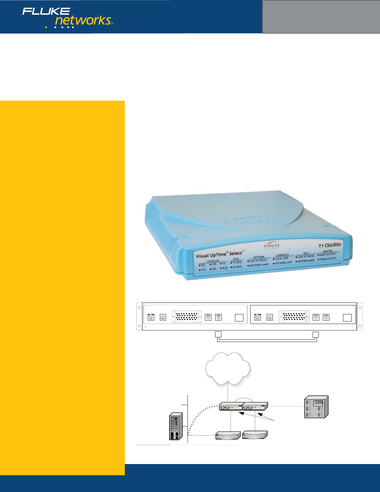
Technical Data
Dual-port Dual-analysis ASE
T1 CSU/DSU with DSX-1 and Drop-and-Insert capabilities
Key features
Inband management capabilities
Multi-Protocol or IP Transport software
Service Level Agreement (SLA) metrics
Drop-and-Insert capabilities through
DSX port
Voice over IP (VoIP) analysis capability
Application analysis capability
LMI spoofi ng
LAN management port
Second analysis port for redundant
router, different traffi c types
Power loss detection
Realtime events
•
•
•
•
•
•
•
•
•
•
•
T1 CSU/DSU model 807-0100 rear view
T1 CSU/DSU model 807-0100 on network
Visual UpTime Select
ASE model 807-0100
ASE 2 ASE 1
ASE 2 PORT 2 ASE 1 PORT 1
T1 DSX
T1-DSX Cable (801-0096)
T1 CSU/DSU model 807-0109 front view (ASE model 100 is two model 109 units in a rack mount)
The Visual UpTime® Select™ Dual-port Dual-analysis
T1 CSU/DSU ASE is deployed on a T1 access line at the
demarcation point between the provider network and
customer premises. It supports frame relay/HDLC and
IP Transport capabilities.
This unit combines two model 109 T1 CSU/DSU ASEs
with a built-in connector cable and analyzes data on
both ports. The unit’s second port can be used for
a redundant router in the event of primary router
failure. Multiple traffi c types can be concentrated on
separate frame relay ports (for example, voice over
FR1, plus SNA over FR2). In addition, domestic and
international frame relay services can exist on two
separate ports on the same access line.
In addition to performing standard CSU/DSU
functions—such as BER tests, loopbacks, and power
failure detection—the ASE is capable of inserting
management traffi c. Up to 155 PVCs or IP circuits can
be managed per ASE.
V.35 Ports
CSU/DSU
Dual-port ASE
data 1 data 2
Optional LAN
Connection on
data 1
PBX
Wide Area
Network
PBX
DSX-1

NETWORKSUPERVISION
Fluke Networks
P.O. Box 777, Everett, WA USA 98206-0777
Fluke Networks operates in more than 50 countries
worldwide. To fi nd your local offi ce contact details, go to
www.fl ukenetworks.com/contact.
©2006 Fluke Corporation. All rights reserved.
Printed in U.S.A. 2/2006 264xxxx D-ENG-N Rev A
What are ASEs?
ASEs (Analysis Service Elements) are data
collection and network performance monitor-
ing hardware devices placed on a wide area
network (WAN) or Local Area Network (LAN)
as part of the Visual UpTime Select system,
which offers in-depth, real-time, and historical
visibility into the performance of your
applications infrastructure. In the system,
data gathered by ASEs is stored in the Visual
UpTime Select server and displayed and ana-
lyzed from the Visual UpTime Select Web client.
As a service level management tool, ASEs
indicate when services are being met, provide
warnings when services start to degrade, and
send alerts when services are not met.
Hardware Warranties
Enhanced Gold, Bronze, and International
Gold ASE hardware warranty service programs
are available to help you maximize your
investment in Visual UpTime Select. For more
detailed warranty information, visit:
www.fl ukenetworks.com/visualcustomercare
Ordering Information
For more details, please contact your Visual
UpTime Select authorized reseller or
Fluke Networks Sales at (800) 240-4010
or (301) 296-2300.
T1 CSU/DSU ASE specifcations
General Dimensions 8.16” (20.7 cm) x 9.0” (22.8 cm) x 1.62”(4.1 cm)
Plastic case with internal power supply.
Weight 2.10 lbs.
Data Rate 1.544 Mbps synchronous
Timing Mode Derived externally from the T1 network or DSX-1
interface, or internally from the ASE.
Environment Operating Temperature 0o to +40oC (+32o to +104o F)
Storage Temperature -20o to +55oC (-4o to +131o×F)
Clearance Requirement Minimum of 3” (7.62 cm) space on sides.
Operating and Storage
Humidity
10% to 90%, noncondensing
Power Requirements Input 100 to 240 VAC
Frequency 50/60 Hz
Input Current Rating 0.5 amps
T1 Network Interface Line Rate 1.544 Mbps ±50 bps synchronous
Line Format AMI or B9ZS line coding
Framing ESF or D4 framing formats
ESF FDL ANSI T1.403, AT&T TR54016, Both, or None
Input Signal 0dB to -36dB
Output Signal 0, -7.5dB, -15dB, -22.5dB LBO
Pulse Density AT&T 62411
Connector 8-pin modular jack—USOC: RJ48C
Timing Loop, DSX-1, or Internal
Channel Selection 1 to 24 channels in any combination
Network DTE Interface
(Data Port)
Confi guration DCE for interfacing with DTE
Data and Clock Leads ITU-T V.35
Signaling Leads EIA RS-232 (ITU-T V.28)
Data Rates 56 kbps x N or 64 kbps x N (N = 1 through 24)
HDLC Inversion Selectable V.35 data inversion
Transmit Timing Basis Network selected-source timing
Receive Timing Basis SCT, inverted SCT, SCTE
Receive Line Data Not Valid RLSD, CTS
Connector Female 34-pin V.35 connector
DSX-1 Interface Line Rate 1.544 Mbps ±50 bps
Line Format AMI or B8ZS
Framing ESF or D4 (SF)
Input Signal -1dB to -11dB
Line Equalization 0 ft, 133 ft, 266 ft, 399 ft, 533 ft, 655 ft
Connector RJ-45
Channel Selection 1 to 24 channels in any combination
Serial Port Interface Specifi cations 19200 or 9600 bps baud rate, 8 data bits no parity,
1 stop bit, EIA RS-232 DTE electrical format, RJ-45
connector
Ethernet 10/100BaseT
Interface
Bite Rate 10 or 100 Mbps
Connector 8-pin modular jack: RJ-48
