Flyingvoice Network Technology FWR9601 VoIP Wireless Router User Manual
Flyingvoice Network Technology Co., Ltd VoIP Wireless Router Users Manual
UserManual.wiki
>
Flyingvoice Network Technology
>
FWR9601 User Manual
Users Manual
Navigation menu
Upload a User Manual
Namespaces
Wiki Guide
HTML
PDF
Info
Views
User Manual
Discussion / Help
Navigation
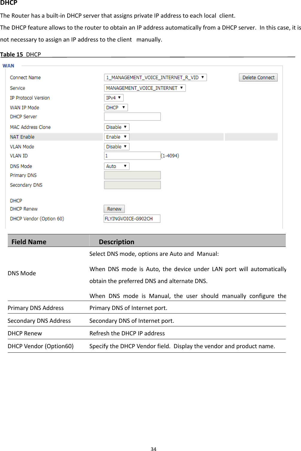
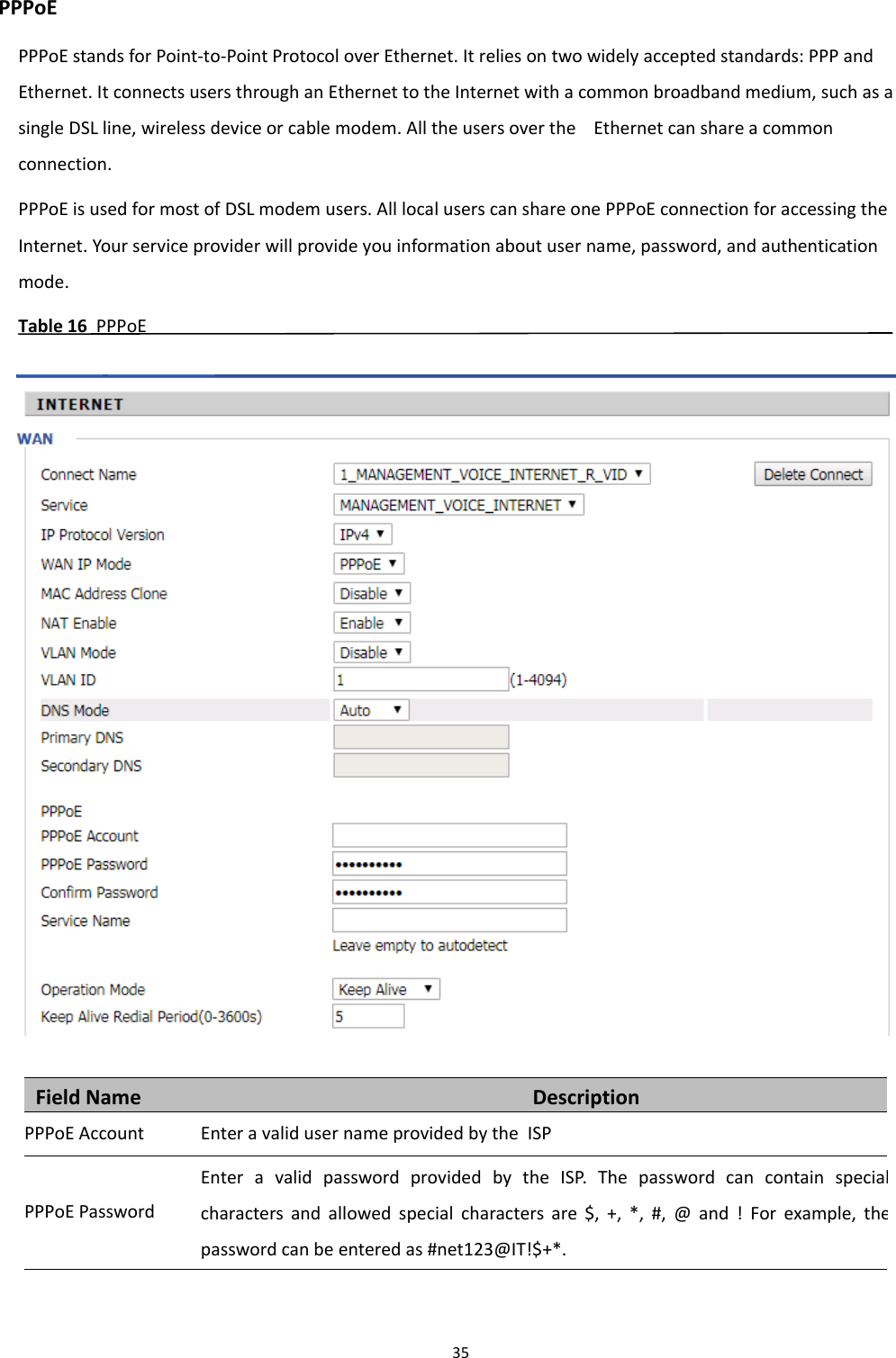
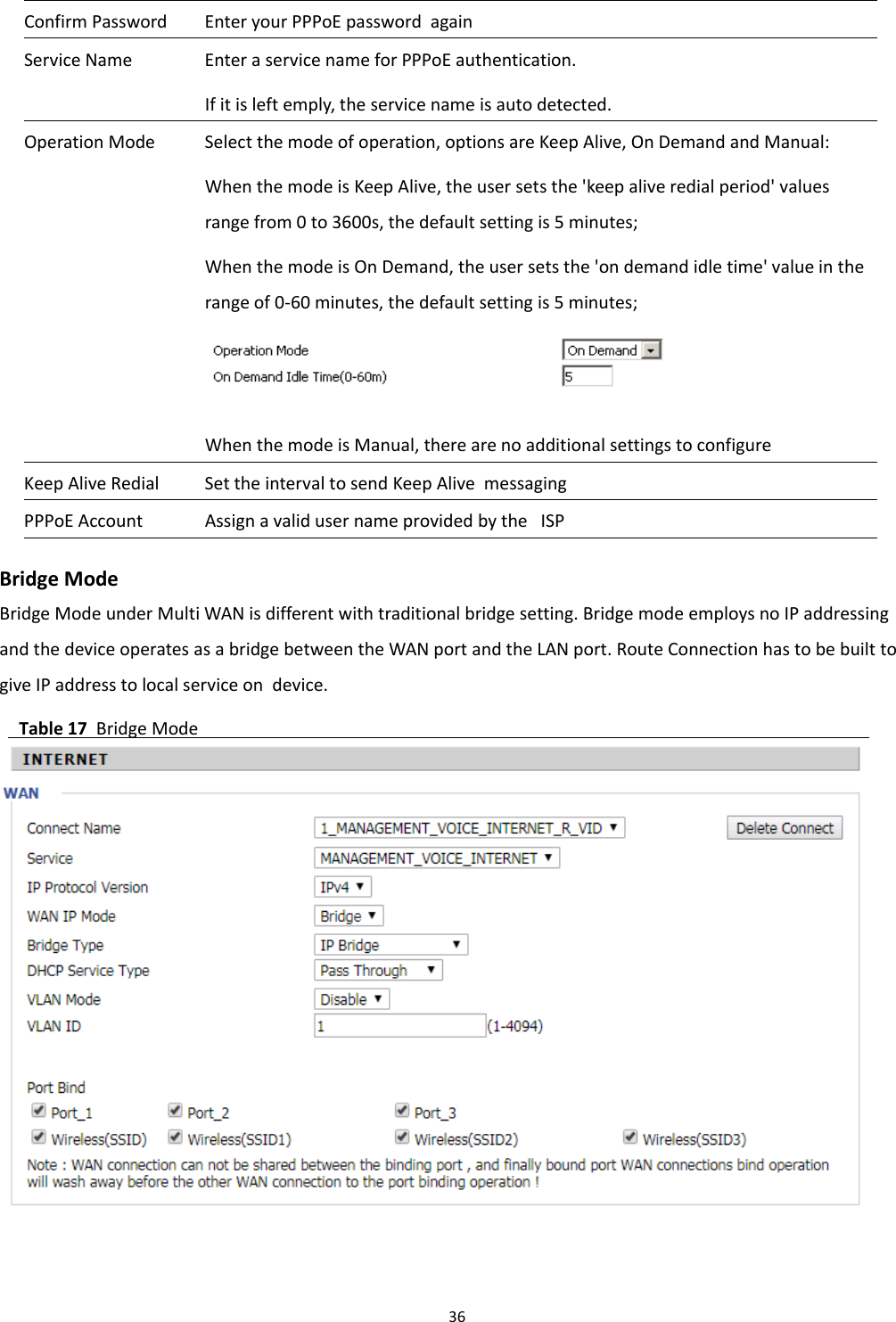
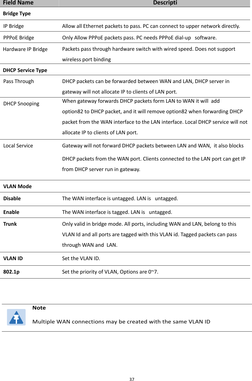
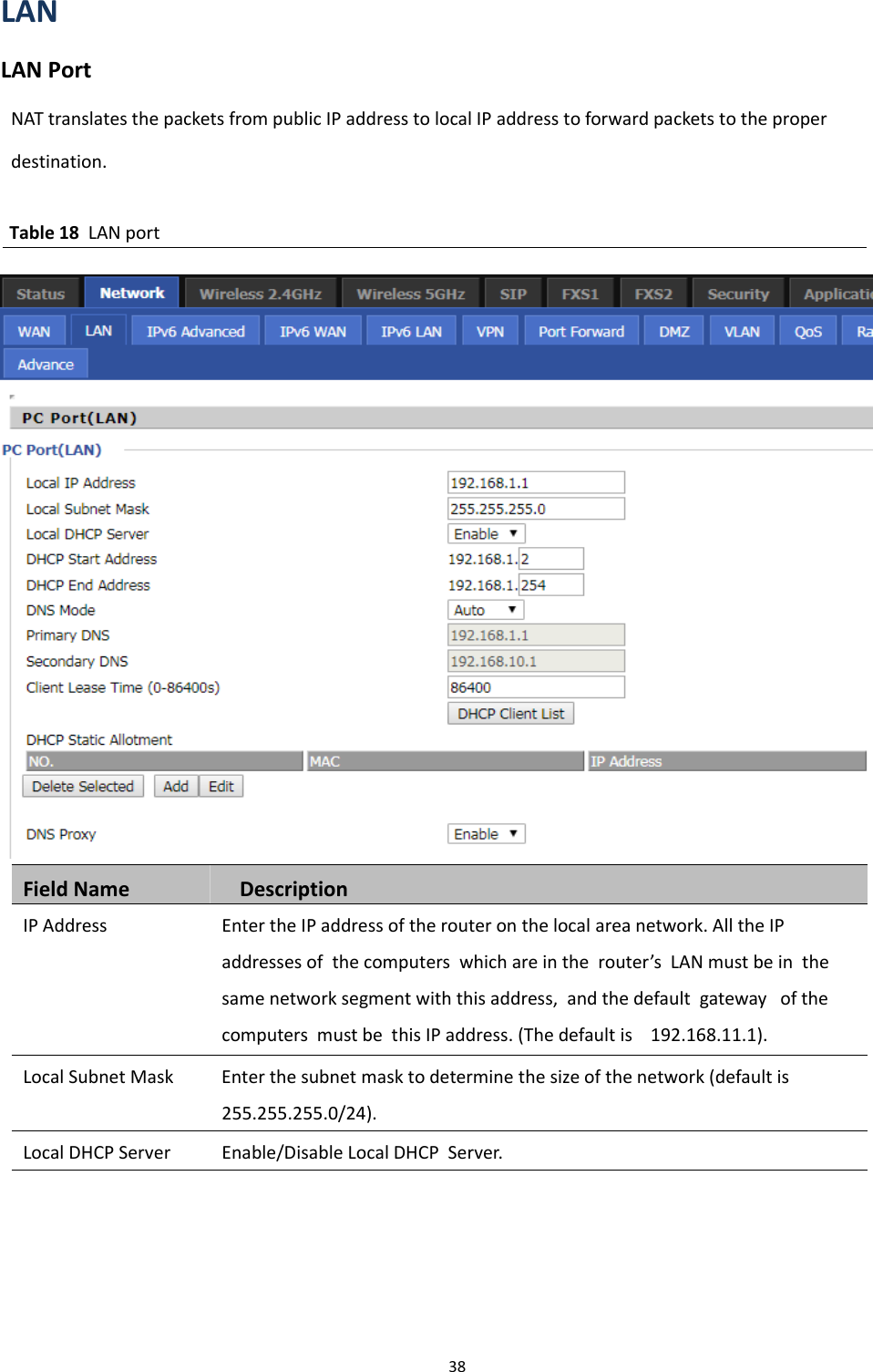
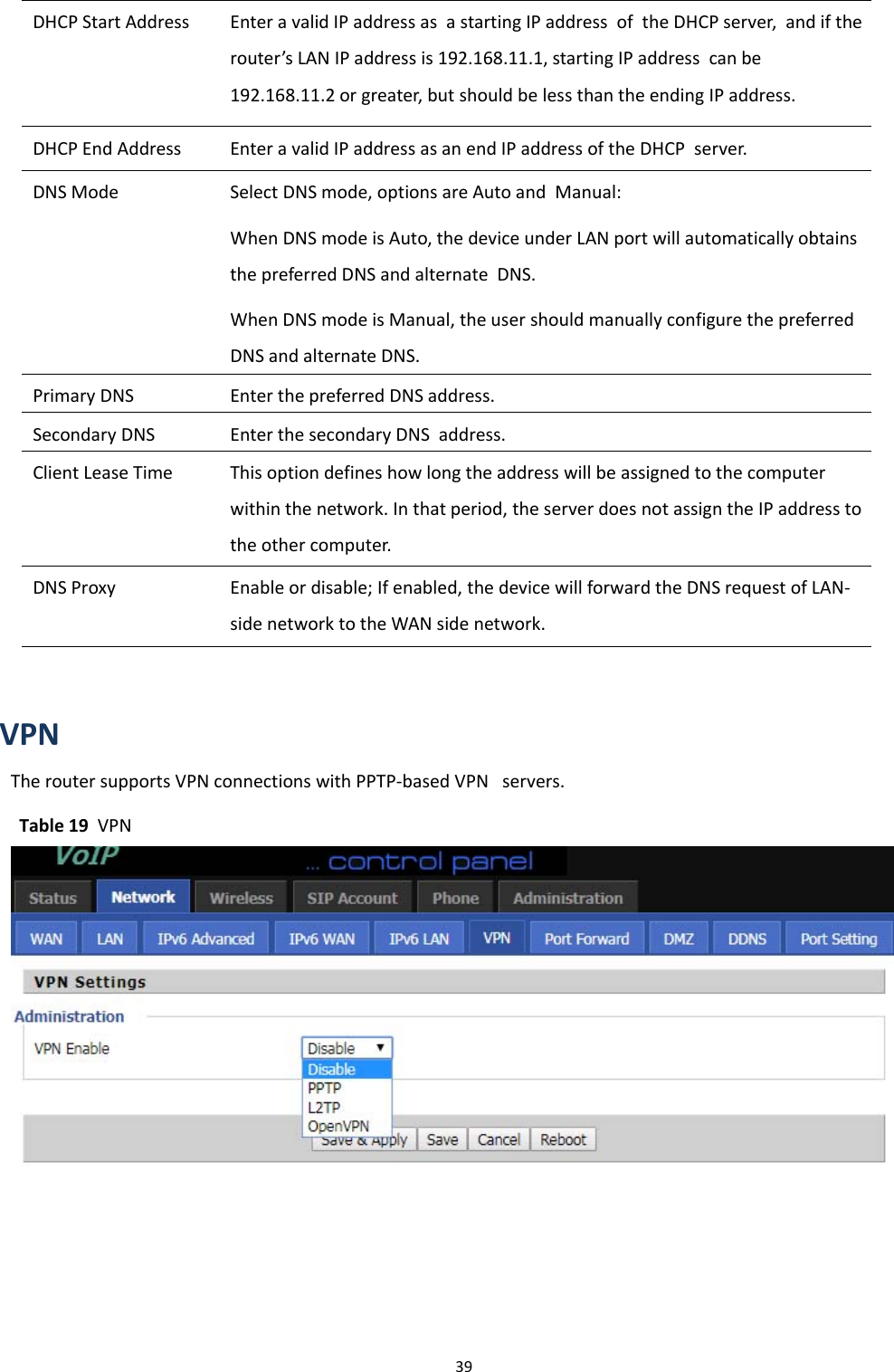
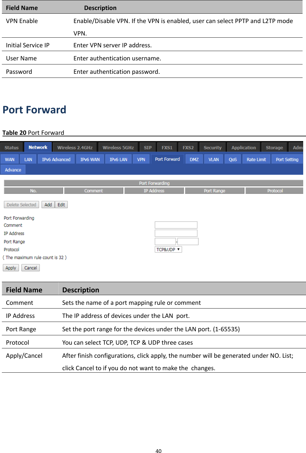
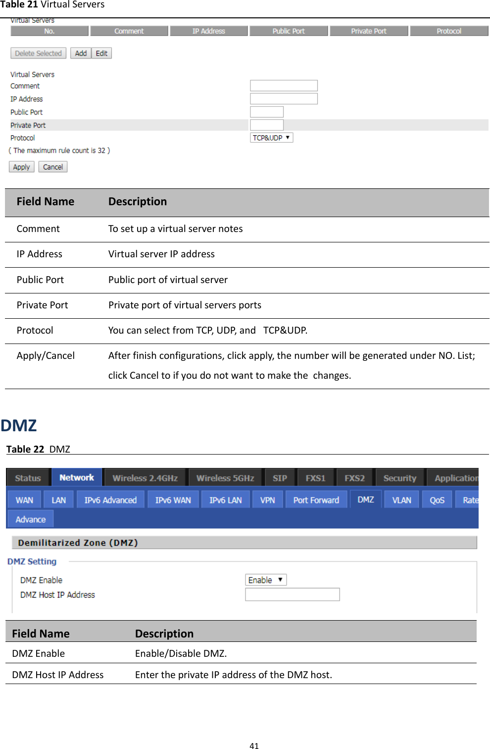
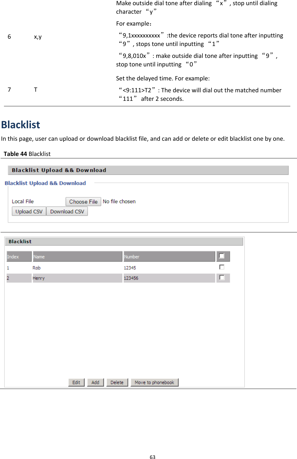
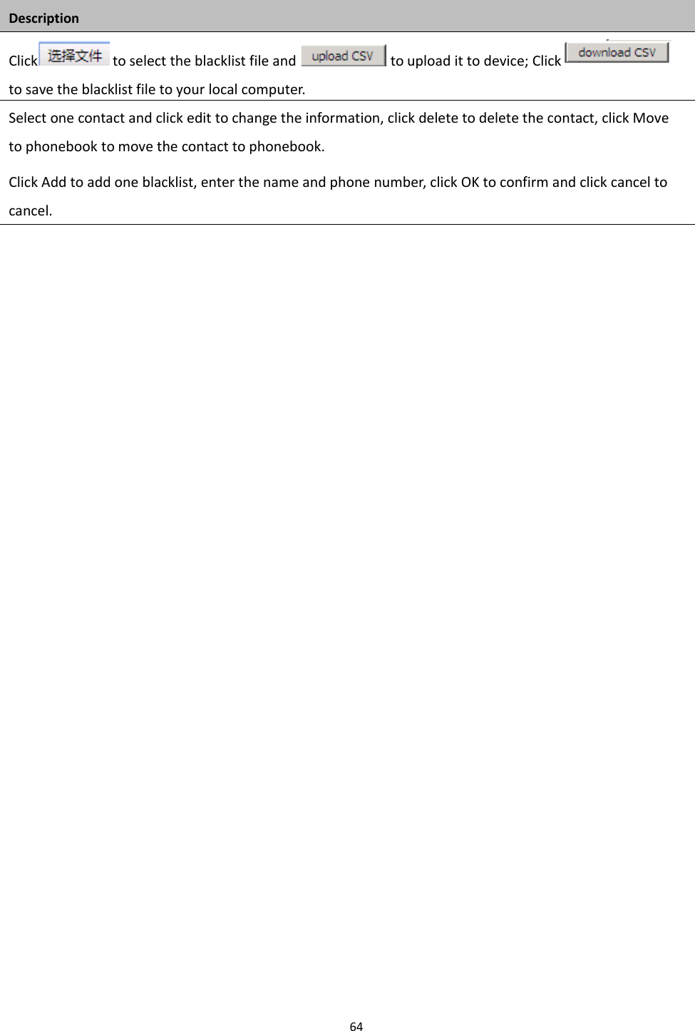
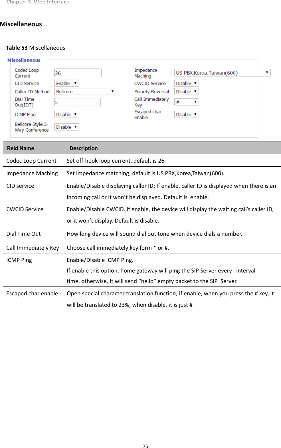
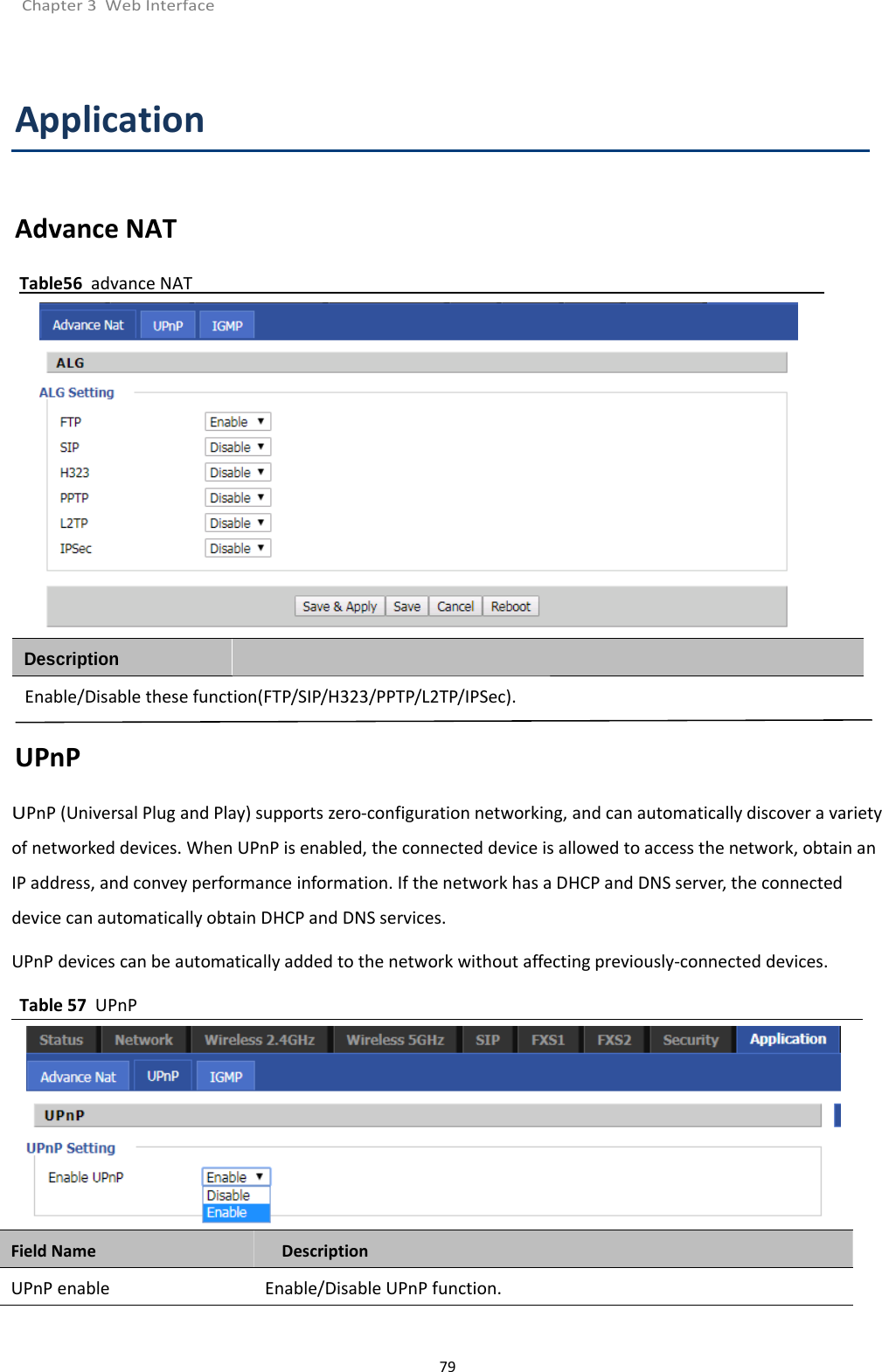
![Chapter 3 Web Interface62Adding one Dial PlanTable 42 Adding one dial planDescriptionStep 1. Enable Dial Plan.Step 2. Click Add button, and the configuration table.Step 3. Fill in the value of parameters.Step 4. Press OK button to end configuration.Dial Plan SyntacticTable 43 Dial Plan SyntacticNo. String Description1 0123456789* # Allowedcharacters2 x Lowercase letter “x” stands for one legal character3[sequence]To match one character form sequence. For example:[0-9]: match one digit form 0 to 9[23-5*]: match one character from 2 or 3 or 4 or 5 or *4x.Match to x, xx, xxx, xxxx and so on.For example:“01” can be match to “0”,”01”,”011”...”011111...” and so on5<dialed:substituted>Replace dialed with substituted.For example:<8:1650>123456:input is “85551212”, output is“16505551212”](https://usermanual.wiki/Flyingvoice-Network-Technology/FWR9601/User-Guide-4129091-Page-70.png)