Flyingvoice Network Technology FWR9601 VoIP Wireless Router User Manual
Flyingvoice Network Technology Co., Ltd VoIP Wireless Router Users Manual
Users Manual

User Manual

FWR9601 User Manual
About This User Guide..............................................................................................................................................1
Contacting FlyingVoice........................................................................................................................1
Purpose................................................................................................................................................2
Cross references..................................................................................................................................2
Feedback............................................................................................................................................. 2
Declaration of Conformity...........................................................................................................................3
Part 15 FCC Rules................................................................................................................................3
Warnings and Notes.................................................................................................................................... 4
Warnings..............................................................................................................................................4
Notes................................................................................................................................................... 4
Chapter 1 Product description............................................................................................................................... 5
FWR9601......................................................................................................................................................6
LED Indicators and Interfaces......................................................................................................................7
Hardware Installation........................................................................................................................10
IVR Voice Prompt.......................................................................................................................................12
Chapter 2 Basic Settings........................................................................................................................................ 17
Two-Level Management...........................................................................................................................18
Web Management Interface.............................................................................................................18
Web Management Interface Details.........................................................................................................20
Satus...................................................................................................................................................... 20
Setting the Time Zone.......................................................................................................................21
Configuring an Internet Connection................................................................................................. 22
Setting up Wireless Connections...................................................................................................... 24
Encryption......................................................................................................................................... 25
Configuring Session Initiation Protocol............................................................................................ 26
SIP Accounts......................................................................................................................................26
Viewing the Registration Status........................................................................................................28
Making a Call..................................................................................................................................... 29
Chapter 3 Web Interface............................................................................................................................. 31
Login...........................................................................................................................................................32
Status......................................................................................................................................................... 33
Contents
FWR9601 User Manual
Network and Security................................................................................................................................34
WAN...................................................................................................................................................34
LAN.................................................................................................................................................... 39
VPN....................................................................................................................................................40
Port Forward..................................................................................................................................... 41
DMZ................................................................................................................................................... 42
Port Setting........................................................................................................................................43
Routing.............................................................................................................................................. 43
Advance.............................................................................................................................................44
Wireless 2.4GHz.........................................................................................................................................45
Wireless Security...............................................................................................................................48
WMM.................................................................................................................................................51
WDS................................................................................................................................................... 51
WPS....................................................................................................................................................52
Station Info........................................................................................................................................53
Advanced...........................................................................................................................................54
Wireless 5GHz............................................................................................................................................56
Wireless Security...............................................................................................................................58
WMM.................................................................................................................................................59
WDS................................................................................................................................................... 59
WPS....................................................................................................................................................59
Station Info........................................................................................................................................59
Advanced...........................................................................................................................................59
SIP......................................................................................................................................................60
SIP Settings........................................................................................................................................60
Dial Plan.............................................................................................................................................62
Blacklist..............................................................................................................................................64
Call Log.............................................................................................................................................. 66
FXS 1...........................................................................................................................................................67
Preferences....................................................................................................................................... 73
Security...................................................................................................................................................... 77
Filtering Setting................................................................................................................................. 77
Content Filtering............................................................................................................................... 78
Application.................................................................................................................................................80
Disk Management............................................................................................................................. 82
FTP Setting.........................................................................................................................................83
SMB Setting.......................................................................................................................................84
Administration...........................................................................................................................................85
Management ....................................................................................................................................85
Firmware Upgrade............................................................................................................................ 90
FWR9601 User Manual
Provision............................................................................................................................................90
SNMP.................................................................................................................................................92
TR-069................................................................................................................................................93
Diagnosis........................................................................................................................................... 94
Operating Mode................................................................................................................................96
System Log.........................................................................................................................................96
Logout................................................................................................................................................96
Reboot............................................................................................................................................... 97
Chapter 4 IPv6 address configuration..................................................................................................................98
Introduction.......................................................................................................................................99
IPv6 Advance...................................................................................................................................100
Configuring IPv6.............................................................................................................................. 100
Viewing WAN port status................................................................................................................102
IPv6 DHCP configuration for LAN/WLAN clients............................................................................ 102
LAN DHCPv6.................................................................................................................................... 103
Chapter 5 Troubleshooting Guide......................................................................................................................104
Configuring PC to get IP Address automatically............................................................................. 105
Cannot connect to the Web............................................................................................................106
Forgotten Password........................................................................................................................106

Table FWR9601 User Manual
Table 1 Features at-a-glance................................................................................................................................... 6
Table 2 LED Indicators............................................................................................................................................. 7
Table 3 Interfaces.................................................................................................................................................... 8
Table 4 IVR Menu Setting Options......................................................................................................................... 11
Table 5 Web management interface......................................................................................................................19
Table 6 Setting time zone.......................................................................................................................................20
Table 7 Configuring an internet connection......................................................................................................... 21
Table 8 Wireless > Basic web page (user view)......................................................................................................23
Table 9 Wireless Security web page.......................................................................................................................24
Table 10 Configuring SIP the Web Management Interface................................................................................. 26
Table 11 Registration status....................................................................................................................................27
Table 12 Login details.............................................................................................................................................31
Table 13 Status....................................................................................................................................................... 32
Table 14 Internet.................................................................................................................................................... 33
Table 15 DHCP........................................................................................................................................................ 34
Table 16 PPPoE....................................................................................................................................................... 35
Table 17 Bridge Mode............................................................................................................................................ 36
Table 18 LAN port...................................................................................................................................................38
Table 19 VPN...........................................................................................................................................................39
Table 20 Port Forward.............................................................................................................................................40
Table 21 Virtual Servers...........................................................................................................................................41
Table 22 DMZ..........................................................................................................................................................41
Table 23 P
ort setting..............................................................................................................................................42
Table 24 Routing......................................................................................................................................................42
Table 25 Advance.................................................................................................................................................... 43
Table 26 Basic......................................................................................................................................................... 44
Table 27 Wireless security.......................................................................................................................................47
Table 28 WiFI Security Setting.................................................................................................................................47
Table 29 WPA-PSK................................................................................................................................................... 48
Table 30 WPAPSKWPA2PSK.................................................................................................................................... 49
Table
Table FWR9601 User Manual
Table 31 Wireless Access Policy............................................................................................................................. 49
Table 32 WMM.......................................................................................................................................................50
Table 33 WDS..........................................................................................................................................................50
Table 34 WPS..........................................................................................................................................................51
Table 35 Station info...............................................................................................................................................52
Table 36 Advanced.................................................................................................................................................. 53
Table 37 Basic......................................................................................................................................................... 55
Table 38 Wireless security.......................................................................................................................................57
Table 39 SIP Settings............................................................................................................................................... 59
Table 40 VoIP QoS................................................................................................................................................... 60
Table 41 Dial Plan................................................................................................................................................... 61
Table 42 Adding one dial plan.................................................................................................................................62
Table 43 Dial Plan Syntactic.....................................................................................................................................62
Table 44 Blacklist..................................................................................................................................................... 63
Table 45 Call log.......................................................................................................................................................65
Table 46 Line...........................................................................................................................................................66
Table 47 Audio configuration.................................................................................................................................67
Table 48 Supplementary service.............................................................................................................................68
Table 49 Advanced.................................................................................................................................................. 69
Table 50 Preferences...............................................................................................................................................72
Table 51 Regional................................................................................................................................................... 72
Table 52 Features and call forward........................................................................................................................73
Table 53 Miscellaneous...........................................................................................................................................75
Table 54 Filtering Setting........................................................................................................................................76
Table 55 Content Filtering.......................................................................................................................................77
Table56 advance NAT.............................................................................................................................................79
Table 57 UPnP.........................................................................................................................................................79
Table 58 IGMP........................................................................................................................................................ 80
Table 59 Disk Management.....................................................................................................................................81
Table 60 FTP Setting................................................................................................................................................ 82
Table 61 SMB Setting...............................................................................................................................................83
Table62 SaveConfigFile
........................................................................................................................................84
Table 63 Administrator settings..............................................................................................................................85
Table 64 NTP settings............................................................................................................................................. 86
Table FWR9601 User Manual
Table 65 Daylight Saving Time................................................................................................................................87
Table 66 System log Setting.................................................................................................................................... 87
Table 67 Factory Defaults Setting........................................................................................................................... 88
Table 68 Factory Defaults.......................................................................................................................................88
Table 69 Firmware upgrade................................................................................................................................... 89
Table 70 Provision................................................................................................................................................... 90
Table 71 Firmware Upgrade...................................................................................................................................91
Table 72 SNMP........................................................................................................................................................91
Table 73 TR069 .......................................................................................................................................92
Table 75 Operating mode.......................................................................................................................................95
Table 76 System log.................................................................................................................................................95
Table 77 Logout...................................................................................................................................................... 95
Table 78 IPv6 Modes.............................................................................................................................................. 98
Table 79 Enabling IPv6............................................................................................................................................99
Table 80 Configuring Statefull IPv6.........................................................................................................................99
Table 81 Configuring Stateless IPv6......................................................................................................................100
About This User Manual
This guide contains the following chapters:
Chapter 1 Product description
Chapter 2 Configuring Basic Settings
Chapter 3 Web Interface
Chapter 4 IPv6 address configuration on WAN interface
Chapter 5 Troubleshooting Guide
About This User Guide
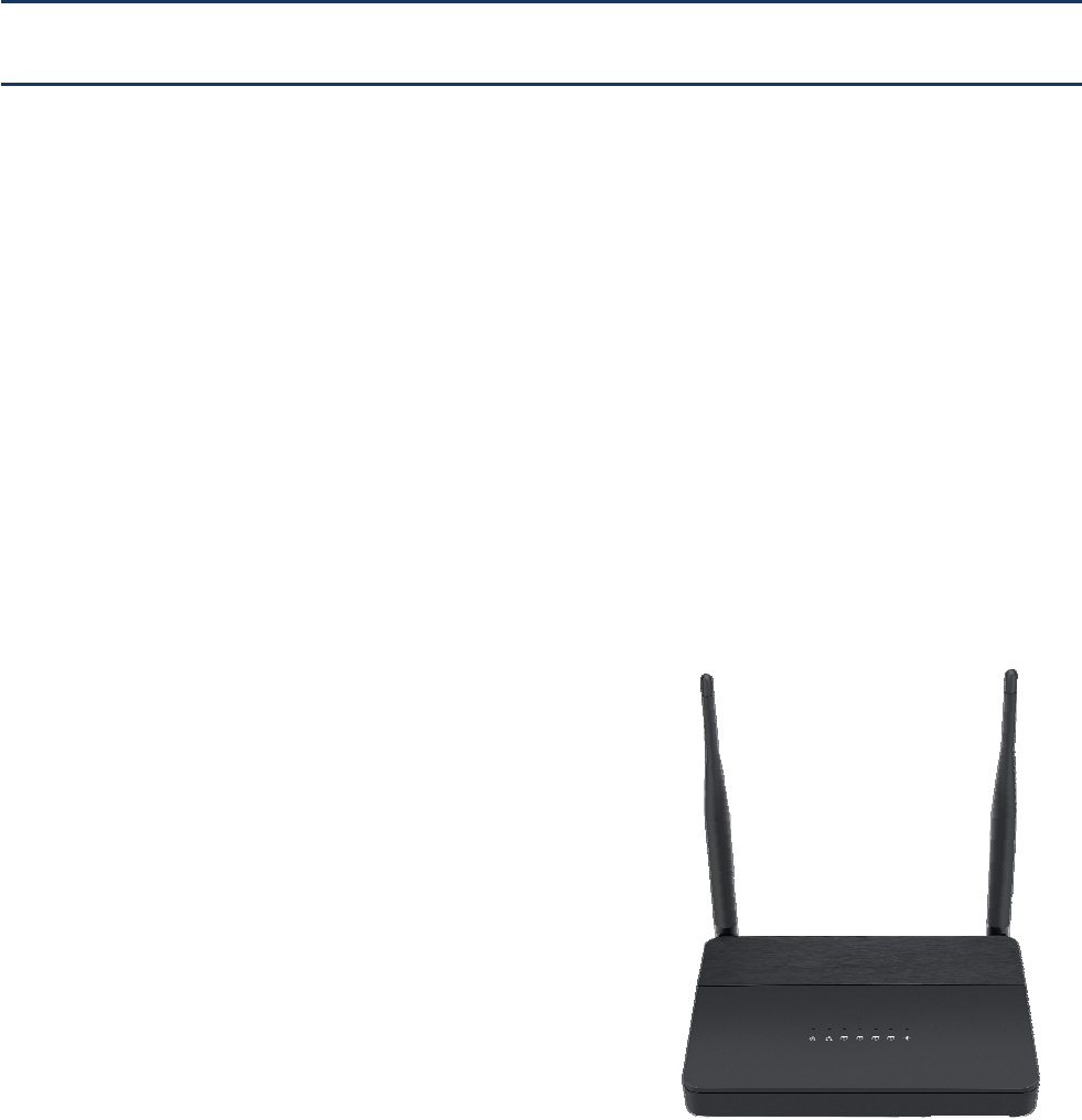
Thank you for choosing FWR9601 wireless router with
VoIP.FWR9601 includes extended functions which support,
USB memory card,This design not only provide users with a
conventional VoIP and routing capabilities. Users can also
take FWR9601 as a FTP server, to share LAN files, pictures
and other resources. Meanwhile, FWR9601 VoIP wireless
router is ideally suited for small and medium enterprises
(SMB) to build wireless office. FWR9601supports
IEEE802.11ac gigabit wireless LAN standard, the highest
wireless speed is up to 867Mbps and it supports both
2.4GHz and 5GHz bands.For VoIP end user, 5G band can
make sure less interference and the transmission quality.
The more, users can enjoy greater bandwidth, and
enhanced data throughput.
About This User Manual
Contacting FlyingVoice
M
ain website: http://www.flyingvoice.com/
Sales e
nquiries:
sales1@flyingvoice.com
S
upport enquiries:
s
upport@flyingvoice.com
Hotline: 010-67886296 0755-26099365
Address: Room508-509, Bldg#1, Dianshi Business Park, No.49 BadachuRd,Shijingshan
District,Beijing,China
About This User Manual
Purpose
The documents are intended to instruct and assist personnel in the operation, installation and
maintenance of the FlyingVoice equipment and ancillary devices. It is recommended that all personnel
engaged in such activities be properly trained.FlyingVoice disclaims all liability whatsoever, implied or
express, for any risk of damage, loss or reduction in system performance arising directly or indirectly
out of the failure of the customer, or anyone acting on the customer's behalf, to abide by the
instructions, system parameters, or recommendations made in this document.
Cross references
References to external publications are shown in italics. Other cross references, emphasized in blue text
in electronic versions, are active links to the references.
This document is divided into numbered chapters that are divided into sections. Sections are not
numbered, but are individually named at the top of each page, and are listed in the table of contents.
Feedback
We appreciate feedback from the users of our documents. This includes feedback on the structure,
content, accuracy, or completeness of our documents. Send feedback to support@flyingvoice.com.
About This User Manual
Declaration of Conformity
Part 15 FCC Rules
This device complies with Part 15 of the FCC Rules. Operation is subject to the following two conditions:
•
This device may not cause harmful interference, and
•
This device must accept any interference received, including interference that may cause
undesired operation.
Warning
Changes or modifications not expressly approved by the party responsible for compliance
could void the user's authority to operate the equipment.
This equipment has been tested and found to comply with the limits for a Class B digital device,
pursuant to Part 15 of the FCC Rules.These limits are designed to provide reasonable protection against harmful
interference in a residential installation. This equipment generates, uses and can radiate radio frequency energy
and, if not installed and used in accordance with the instructions, may cause harmful interference to radio
communications. However, there is no guarantee that interference will not occur in a particular installation.
If this equipment does cause harmful interference to radio or television reception,which can be
determined by turning the equipment off and on, the user is encouraged to try to correct the interference
by one or more of the following measures:
•
Reorient or relocate the receiving antenna.
•
Increase the separation between the equipment and receiver.
•
Connect the equipment into an outlet on a circuit different from that to which the receiver
is connected.
•
Consult the dealer or an experienced radio/TV technician for help
This equipment complies with FCC radiation exposure limits set forth for an uncontrolled environment. This
equipment should be installed and operated with minimum distance 20cm between the radiator & your body.
Indoor use only.

About This User Manual
Warnings and Notes
The following describes how warnings and notes are used in this document and in all documents of the
FlyingVoice document set.
Warnings
Warnings precede instructions that contain potentially hazardous situations. Warnings are used to alert
the reader to possible hazards that could cause loss of life or physical injury. A warning has the
following format:
Warning
Warning text and consequence for not following the instructions in the warning.
Notes
A note means that there is a possibility of an undesirable situation or provides additional
information to help the reader understand a topic or concept. A note has the following format:
Notes
Notes text and consequence for not following the instructions in the Notes.

Chapter 1 Product description
Chapter 1 Product description
This chapter covers:
·FWR9601
·LED Indicators and Interfaces
·Hardware Installation
·Voice Prompt

Chapter 1 Product description
FWR9601
Table 1 Features at-a-glance
Port/Model FWR9601
picture
WAN 1
LAN 4
FXS 1
USB NO
Ethernet
interface
5* RJ45
10/100/1000M
Fax T.30, T.38 Fax
WiFi 2.4G 2T2R(300Mbps)
5G 2T2R (867Mbps)
Voice Code G.711 (A-law, U-law), G.729A/B, G.723, G.722 (Wide band)
Management Voice menu, Web Management, Provision:TFTP/HTTP/HTTPS, TR069, SNMP
VLAN Support

Chapter 1 Product description
LED Indicators and Interfaces
Table 2 LED Indicators
LED Status Explanation
POWER
On (Green) The router is powered on and running normally.
Off The router is powered off.
WAN
On (Green) The port is connected with 100Mbps.
Off The port is disconnected.
Blinking (Green) It will blink while transmitting data.
LAN1/2/3/4
On (Green) The port is connected with 100Mbps.
Off The port is disconnected.
Blinking (Green) It will blink while transmitting data.
2.4G
On (Green) The port is connected with 100Mbps.
Off The port is disconnected.
Blinking (Green) It will blink while transmitting data.
5G
On (Green Wireless access point is ready.
Blinking (Green) It will blink while wireless traffic goes through.
Off The system is not powered on or the WIFI switch is off
PHONE
Blinking (Green) Not registered
On (Green) Registered
Chapter 1 Product description
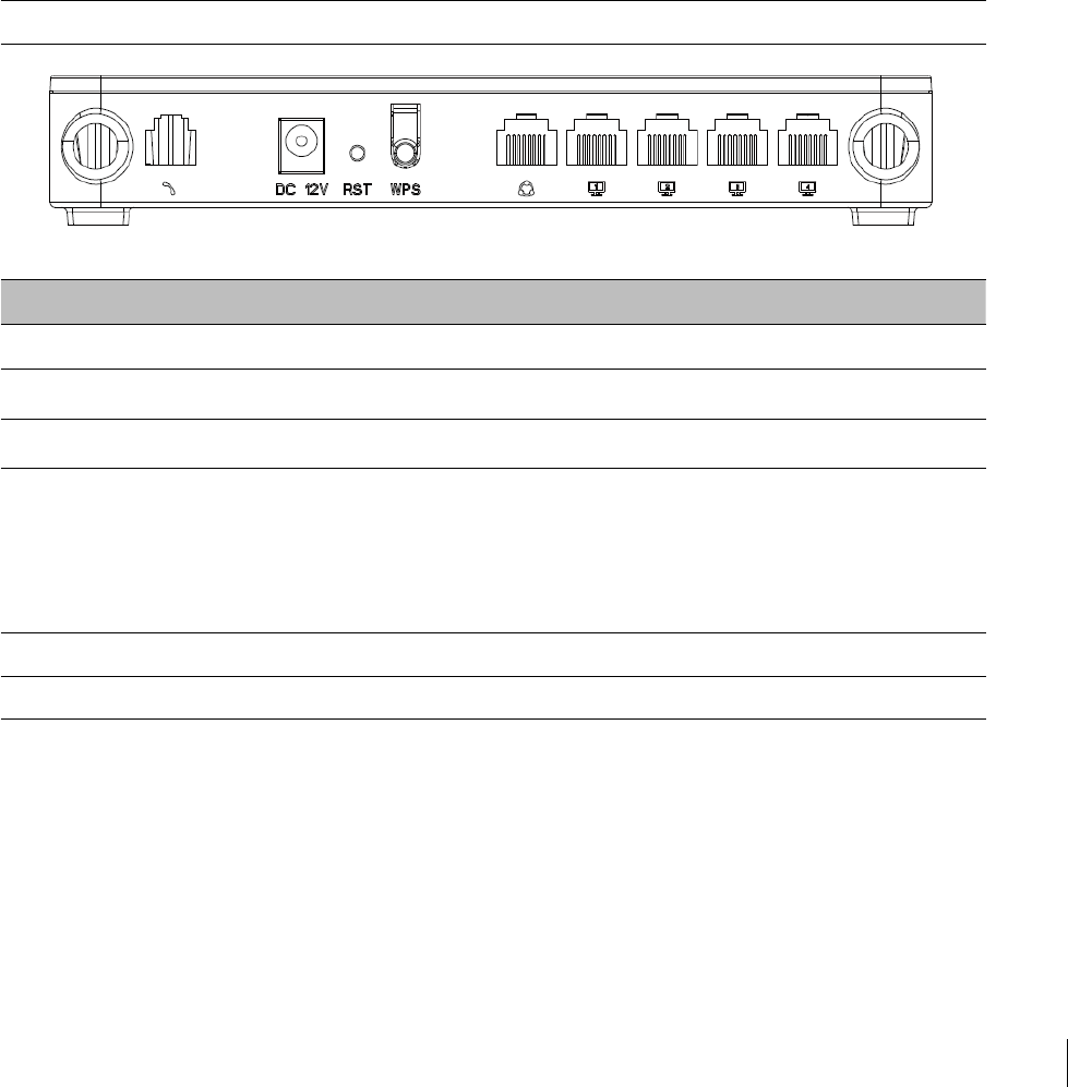
Table 3 Interfaces
FWR9601
Interface Description
Phone1 ATA Analog phone connector
POWER Connector for a power adapter
RESET Restore the factory settings button, press and hold the device after 5s to restore
WPS Wi-Fi security settings, when mobile phones, laptops and other wireless devices to
find the wireless router WiFi signal, when connected, click the WPS button on the
router to complete the wireless router and wireless device encryption
authentication and connection.
WAN Connector for accessing the Internet
LAN 1/2/3/4 Connectors for local networked devices

Chapter 1 Product description
Hardware Installation
Before configuring your router, please see the procedure below for instructions on connecting the device in
your network.
Procedure 1 Configuring the Router
1.
Connect analog phone to ATA Port with an RJ11 cable.
2.
Connect the WAN port to the Interne your network’s modem/switch/router/ADSL
3.
equipment using an Ethernet cable.
4.
Connect one end of the power cord to the power port of the device. Connect the other end to the
wall outlet.
5.
Check the Power, WAN, and LAN LED to confirm network connectivity.
Warning
Please do not attempt to use unsupported power adapters and do not remove power during
configuring or updating the device. Using other power adapters may damage theFWR8102

Chapter 1 Product description
Warning
Changes or modifications not expressly approved by the party responsible for
compliance can void the user’s authority to operate the equipment.
This equipment has been tested and found to comply with the limits for a Class B digital
device, pursuant to Part 15 of the FCC Rules. These limits are designed to provide reasonable
protection against harmful interference in a residential installation. This equipment
generates, uses and can radiate radio frequency cause harmful interference to radio
communications. However, there is no energy and, if not installed and used in accordance
with the instructions, may guarantee that interference will not occur in a particular
installation.
If this equipment does cause harmful interference to radio or television reception, which can
be determined by turning the equipment off and on, the user is encouraged to try to correct
the interference by one or more of the following measures:
•
R
eorient or relocate the receiving antenna.
•
Increase the separation between the equipment and receiver.
•
Connect the equipment into an outlet on a circuit different from that to which the receiver
is connected.

Chapter 1 Product description
IVR Voice Prompt
The devices may be configured by navigating the unit’s voice menu. By using your phone and
dialing a sequence of commands, the device can be configured for operation. Each device
configuration section may be accessed by entering a certain operation code, as shown below.
Table 4 IVR Menu Setting Options
Operation
code Menu Navigation
1
Network port
configuration
(1)
WAN Port
Connection
Type
1.
Pick up phone and press “****” to start IVR
2.
Choose “1”, and The router reports the current WAN port connection type
3.
Prompt "Please enter password”, user needs to input password and press “#”
key, if user wants to configuration WAN port connection type.
The password in IVR is same as web management interface login, the user may
use phone keypad to enter password directly
For example: WEB login password is “admin”, so the password in IVR is “admin”.
The user may “23646” to access and then configure the WAN connection port.
The unit reports “Operation Successful” if the password is correct.
4.
Prompt "Please enter password”, user needs to input password and press “#”
key if user wants to configuration WAN port connection type.
5.
Choose the new WAN port connection type (1) DHCP or (2) Static
The unit reports “Operation Successful” if the changes are successful. The router
returns to the prompt “please enter your option …”
6.
To quit, enter “*”

Chapter 1 Product description
(2)
WAN Port IP
Address
1.
Pick up phone and press “****” to start IVR
2.
Choose “2”, and The router reports current WAN Port IP Address
3.
Input the new WAN port IP address and press “#” key:
4.
Use “*” to replace “.”, for exampleuser can input 192*168*20*168 to set the
new IP address 192.168.20.168
5.
Press # key to indicate that you have finished
6.
Report “operation successful” if user operation is ok.
7.
To quit, enter “**”.
(3)
WAN Port
Subnet Mask
1.
Pick up phone and press “****” to start IVR
2.
Choose “3”, and router reports current WAN port subnet mask
3.
Input a new WAN port subnet mask and press # key:
4.
Use “*” to replace “.”, user can input 255*255*255*0 to set the new WAN
port subnet mask 255.255.255.0
5.
Press “#” key to indicate that you have finished
6.
Report “operation successful” if user operation is ok.
7.
To quit, enter “**”.
(4)
Gateway
1.
Pick up phone and press “****” to start IVR
2.
Choose “4”, and the router reports current gateway
3.
Input the new gateway and press “#” key:
4.
Use “*” to replace “.”, user can input 192*168*20*1 to set the new gateway
192.168.20.1.
5.
Press “#” key to indicate that you have finished.
6.
Report “operation successful” if user operation is ok.
7.
To quit, press “**”.

Chapter 1 Product description
(5)
DNS
1.
Pick up phone and press “****” to start IVR
2.
Choose “5”, and the router reports current DNS
3.
Input the new DNS and press # key:
4.
Use “*” to replace “.”, user can input 192*168*20*1 to set the new gateway
192.168.20.1.
5.
Press “#” key to indicate that you have finished.
2
Phone port
configuration
1. Pick up phone and press “****” to start IVR
2. Select "2", then the device will continue to broadcast prompts the user to select
current phone number; 2. registration server address; 3. registration port; 4. call
forwarding configuration,5. DNS configuration ;
3. Continue pressing "1" and the unit will continue to broadcast the phone number
of the current phone port. The device will then broadcast "1. Phone number ..."
again.
3
F
actory Reset
1.
Pick up phone and press “****” to start IVR
2.
Choose “3”, and the router reports “Factory Reset”
3.
Prompt "Please enter password", the method of inputting password is the same
as operation 1.
4.
If you want to quit, press “*”.
5.
Prompt “operation successful” if password is right and then the router will be in
factory default configuration.
4
Reboot
1.
Pick up phone and press “****” to start IVR
2.
Choose “4”, and the router reports “Reboot”
3.
Prompt "Please enter password", the method of inputting password is same as
operation 1.
4.
the router reboots if password is right and operation
5
W
AN Port
Login
1.
Pick up phone and press “****” to start IVR
2.
Choose “5”, and the router reports “WAN Port Login”
3.
Prompt "Please enter password", the method of inputting password is same as
operation 1.
4.
If user wants to quit, press “*”.

Chapter 1 Product description
14
6
WEB Access
Port
1.
Pick up phone and press “****” to start IVR
2.
Choose “6”, and the router reports “ WEB Access Port”
3.
Prompt “Please enter password”, the method of inputting password is same as
operation 1.
4.
Report “operation successful” if user operation is ok.
5.
Report the current WEB Access Port
7
F
irmware
Versio
n
1.
Pick up phone and press “****” to start IVR
2.
Choose “7” and the router reports the current Firmware version

Chapter 1 Product description
15
Note
1.While using Voice menu, press * (star) to return to main menu.
2.If any changes made in the IP assignment mode, the router must be rebooted in order
for the settings to take effect.
3.While entering an IP address or subnet mask, use "*" (star) to enter "." (Dot) and use
"#" (hash) key to finish entering IP address or subnet mask:
4.For example, to enter the IP address 192.168.20.159 by keypad, press these keys:
192*168*20*159, use the #(hash) key to indicate that you have finished entering the
IP address.
5.Use the # (hash) key to indicate that you have finish entering the IP address or subnet
mask
6.While assigning an IP address in Static IP mode, setting the IP address, subnet mask
and default gateway is required to complete the configuration. If in DHCP mode,
please make sure that a DHCP server is available in your existing broadband
connection to which WAN port of FWR8102 is connected.
7.The default LAN port IP address of FWR8102 is 192.168.11.1 and this address should
not be assigned to the WAN port IP address of FWR8102 in the same network segment
of LAN port.
8.The password can be entered using phone keypad, the mapping table between number
and letters as follows:
Toinput:D,E,F,d,e,f--press‘3’
Toinput:G,H,I,g,h,i--press‘4’
Toinput:J,K,L,j,k,l--press‘5’
To input: M, N, O, m, n, o -- press ‘6’
Toinput:P,Q,R,S,p,q,r,s--press‘7’
Toinput:T,U,V,t,u,v--press‘8’
Toinput:W,X,Y,Z,w,x,y,z--press ‘9’
To input all other characters in the administrator password-----press ‘0’,

16
This chapter covers:
•
Two-Level Management
•
Web Management Interface
•
Configuring
•
Making a Call
Chapter 2 Basic Settings
Chapter 2 Basic Settings
17
Two-Level Management
This section explains how to setup a password for an administrator or user and how to adjust basic and
advanced settings.
FWR9601 supports two-level management:
(1) administrator mode operation: please type “admin/admin” on Username/Password and click Login
button to begin configuration.
(2) user mode operation, please type “user/user” on Username/Password and click Login button to begin
configuration.
Web Management Interface
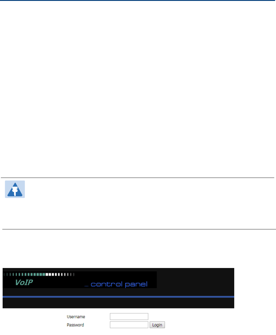
The devices feature a web browser-based interface that may be used to configure and manage the device.
See below for information
Login in from the LAN port
1.Ensure your PC is connected to the router’s LAN port correctly.
Note
You may either set up your PC to get an IP dynamically from the router or set up
the IP
address of the PC to be the same subnet as the default IP address of router is 192.168.1.1.
For detailed information, see Chapter 5: Troubleshooting Guide.
2.Open a web browser on your PC and type “http://192.168.1.1”.
3.The following window appears and prompts for username , password.
4.For administrator mode operation, please type admin/admin on Username/Password and click Login to
begin configuration.
5.Forusermodeoperation,pleasetypeuser/useron Username/Password and click Login to begin
configuration.
Chapter 2 Basic Settings
18
6.The web management interface automatically logs out the user after 5 minutes of inactivity.
Login in from the WAN port
1.Ensure your PC is connected to the router’s WAN port correctly.
2.Obtain the IP addresses of WAN port using Voice prompt or by logging into the device web management
interface via a LAN port and navigating to Network > WAN.
3.Open a web browser on your PC and type http://<IP address of WAN port>. The following login page will
be opened to enter username and password.
4.For administrator mode operation, type admin/admin on Username/Password and click Login to begin
configuration.
5.Forusermodeoperation,typeuser/useronUsername/Password and click Login to begin configuration.
6.The web management interface automatically logs out the user after 5 minutes of inactivity.
Note
If you are unable to access the web configuration, please see Chapter 5Troubleshooting
Guide for more information.
Note
If you fail to access to the web configuration, see Chapter 5 Troubleshooting Guide for
more information.
Chapter 2 Basic Settings
19
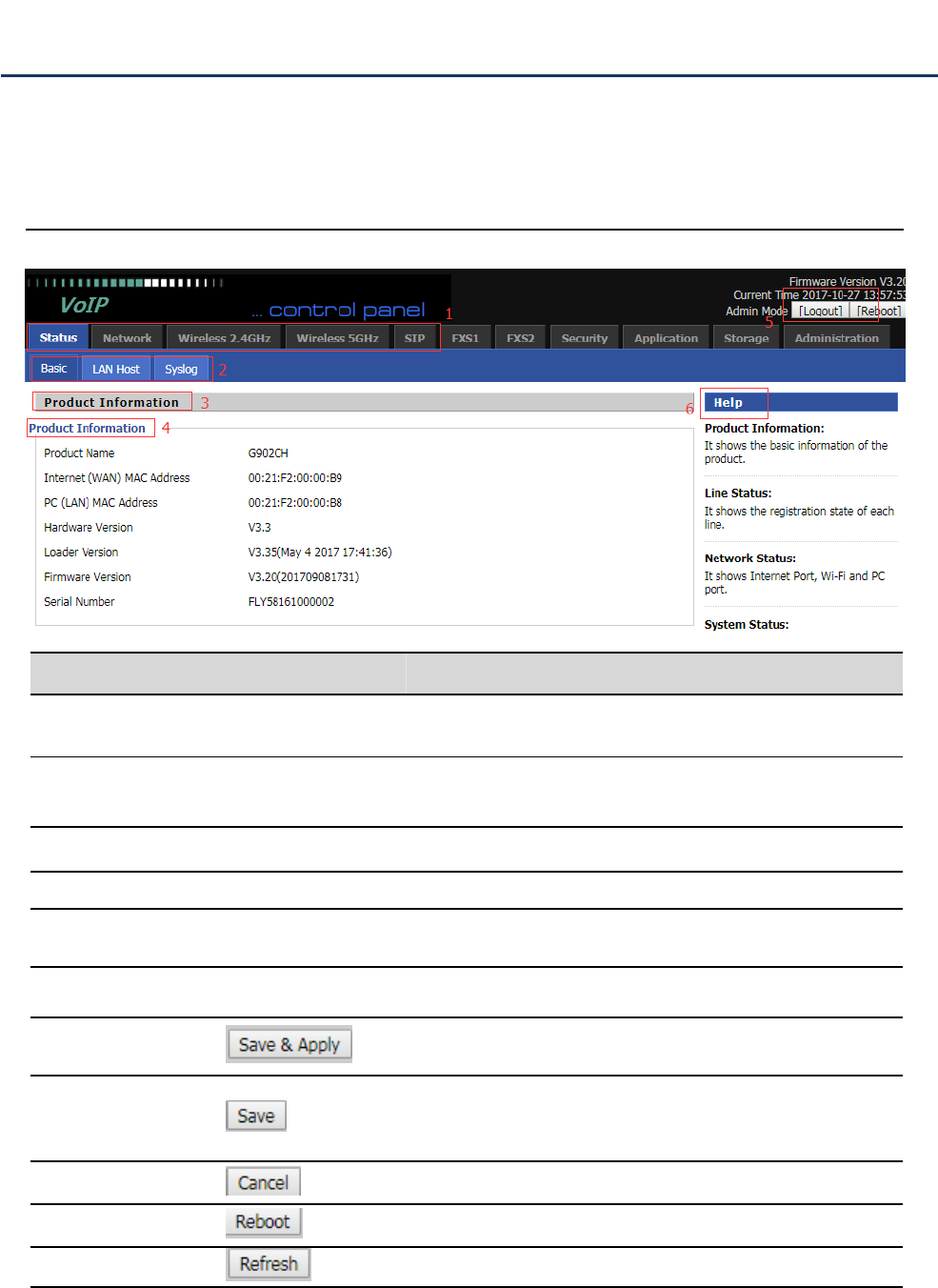
Satus
Table 5 Web management interface
Web Management Interface Details
Serial number Name Description
Postition 1 Main navigation bar Click this navigation bar to bring up the corresponding
child navigation bar
Postition 2 navigation bar Click the sub navigation bar to enter the configuration
page
Postition 3 Product Information Device Information Configuration Title
Postition 4 Product Information Show product information
Postition 5 Login/Logout main information shows the firmware version, DSP
version, current time and management mode.
Postition 6 Help help to display help information, users can get some help
here
Use this button,conifg will be saved and And take effect
immediately
After changing the parameters, you need to click this
button to save. After you click Save, there is a need to
restart the device.
Click to cancel the change
Click to restart
Refresh current page
Chapter 2 Basic Settings
20
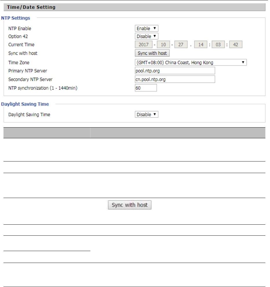
Setting the Time Zone
Table 6 Setting time zone
Field Name Description
NTP Enable Enable NTP (Network Time Protocol) to automatically retrieve time
and date settings for the device
Option 42 Whether to enable Option 42
Current Time When NTP Enable is set to “Disable”, manually configure the time
and date via the Current Time parameter
Sync with host Press button to synchronize the host PC
date, time and time zone.
Time Zone Select the desired time zone
Primary NTP Server Primary and secondary NTP server address for clock
synchronization. A valid NTP server must be reachable for full NTP
Secondary NTP Server
NTP Synchronization(1 -
1440min)
The synchronization period with NTP (1-1440 minutes), default is
60
Chapter 2 Basic Settings
21
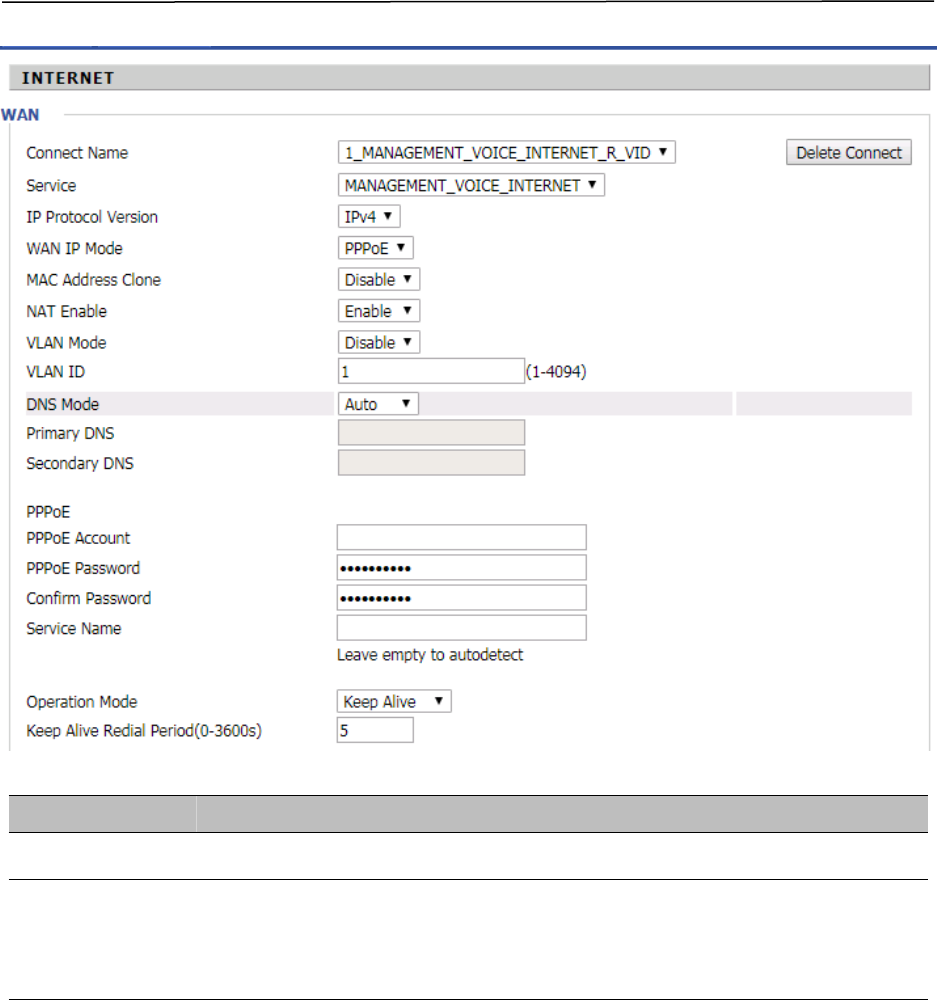
Configuring an Internet Connection
From the Network > WAN page, WAN connections may be inserted or deleted. For more information on
Internet Connection setting, see Table 10below.
Table 7 Configuring an internet connection

Chapter 2 Basic Settings
22
Field Name Description
Connect Name Use keywords to indicate WAN port service model (the parameters are defined
in Network--> multi-WAN page)
Service Chose the service mode for the created connection
IP Protocol Version IPv4 and IPv6 are supported
WAN IP Mode Choose Internet connection mode, DHCP, PPPoE, or Bridge
NAT Enable Enable or disable NAT
VLAN ID Multiple WAN connections may be created with the same VLAN ID
DNS Mode Select DNS mode, options are Auto and Manual:
When DNS mode is Auto, the device under LAN port will automatically obtains
the preferred DNS and alternate DNS.
When DNS mode is Manual, the user should manually configure the preferred
DNS and alternate DNS
Primary DNS Enter the preferred DNS address
Secondary DNS Enter the secondary DNS address
DHCP (Displayed when WAN IP Mode is set to DHCP)
DHCP Renew Refresh the DHCP IP
DHCP Vendor Specify the DHCP Vendor field Display the vendor and product name
Chapter 2 Basic Settings
23
Setting up Wireless Connections
To set up the wireless connection, please perform the following steps.
1.Enable Wireless and Setting SSID
2.Open Wireless > Basic webpage as shown below:
Table 8 Wireless > Basic web page (user view)
Field Name Description
Radio On/Off
Select “Radio Off”to disable wireless operation
Select “Radio on” to enable wireless operation
Please note: “Save” required for this parameter change
Network Mode Choose one network mode from the drop down list.
SSID
The logical name of the wireless connection (text, numbers or various specia
l
characters)
Multiple SSID 1-4 Multiple SSID 1 - 4, configure up to 4 unique SSIDs
broadcast(SSID)
Enabled: The device SSID is broadcast at regular intervals Disabled: The
device SSID is not broadcast at regulatr intervals,
disallowing wi-fi clients from automatically connecting to the FWR8401
AP Isolation
Enabled: Devices connected to the router are isolated from one another on virtua
networks
Disabled: Devices connected to the router are visible on the network to each other
Chapter 2 Basic Settings
24
Encryption
Open Wireless/Wireless Security webpage to configure custom security parameters.
Table 9 Wireless Security web page
MBSSID AP Isolation
Enabled: Devices connected to the router via one of the Multiple SSIDs are isolate
d
from one another on virtual networks
Disabled: Devices connected to the router via one of the Multiple SSIDs are visibl
e
BSSID Basic Service Set Identifier – AP MAC Address Listing
Frquency (Channel) Select the channel of operation for the device from the drop-down list
Operating Mode
Mixed Mode: Packet preamble (only) is transmitted in a format compatible wit
h
legacy 802.11a/g (for 802.11a/g receivers).
Green Field: High throughput packet preambles do not contain legacy formattin
g
Channel Bandwidth 20: the device operates with a 20 MHz channel size 20/40: the device operates wit
h
a 40 MHz channel size

Chapter 2 Basic Settings
25
Configuring Session Initiation Protocol
SIP Accounts
FWR9601 have 1 Line to make SIP (Session Initiation Protocol) calls. Before registering, the device user
should have a SIP account configured by the system administrator or provider. See the section below
for more information.
Field Name Description
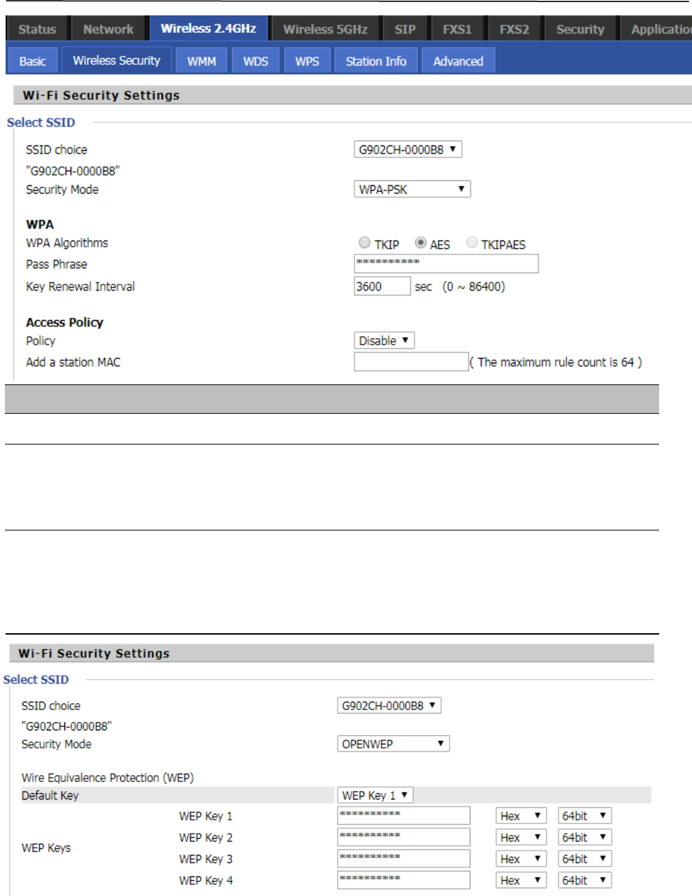
SSID Choice Choose the SSID from the drop-drown list for which security will be configured
Security Mode
Select an appropriate encryption mode to improve the security and privacy of
your wireless data packets.
Each encryption mode will launch an additional web page and ask you to offer
additional configuration.
For high security, the device can be configured for Security Mode as
WPA2-PSK and WPA Algorithms as AES.
WPA Algorithms
This parameter is used to select the encryption of wireless home gateway
algorithms; options are TKIP, AES and TKIPAES.
Pass Phrase Configure the WPA-PSK security password.
Key Renewal Interval Set the key scheduled update cycle, default is 3600s.
Access Policy
Policy
Disable: Access policy rules are not enforced
Allow: Only allow the clients in the station MAC list to access Rejected:
Block the clients in the station MAC list from registering
Add a Station MAC Enter the MAC address of the clients which you want to allow or reject
Chapter 2 Basic Settings
26
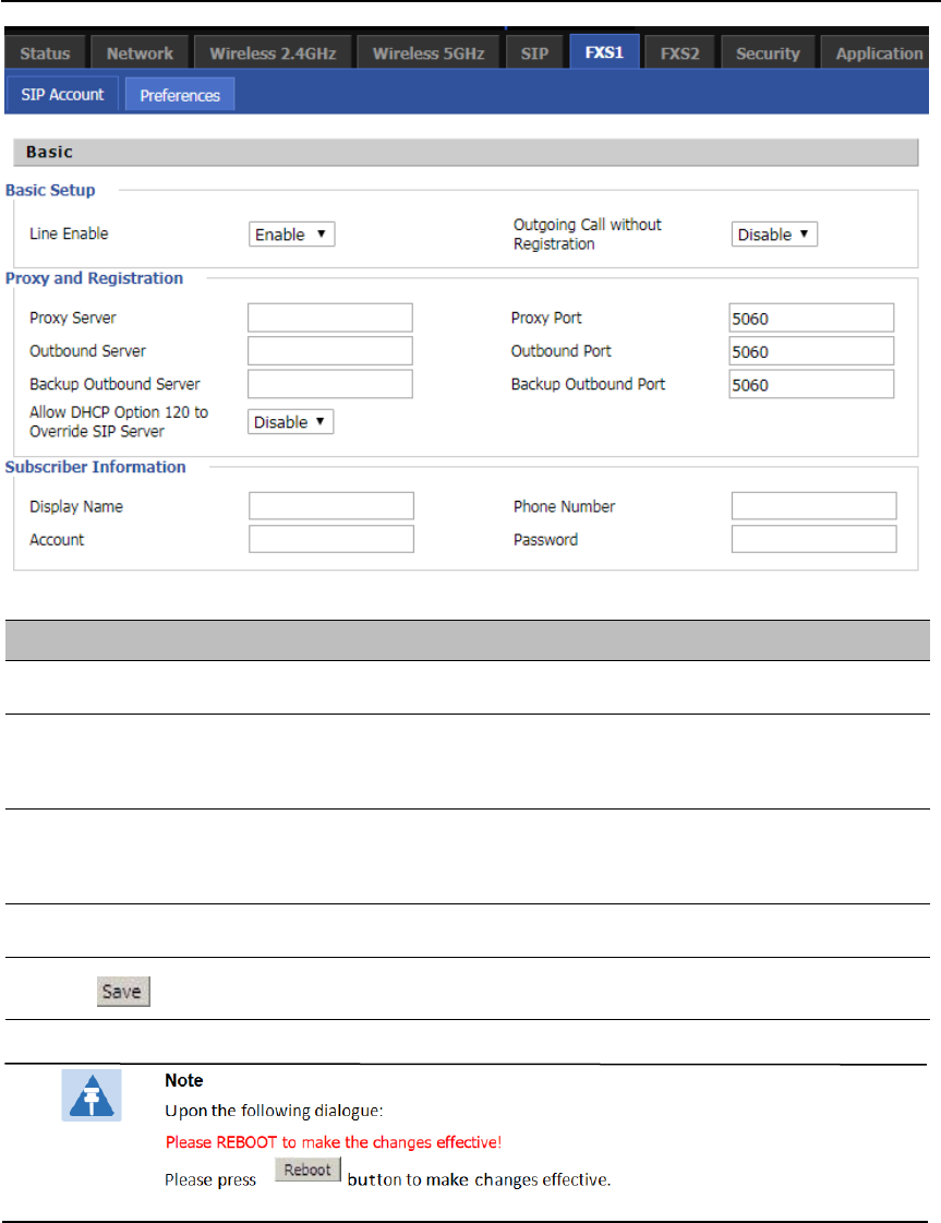
Configuring SIP the Web Management Interface
Table 10 Configuring SIP the Web Management Interface
Procedure
1. Open the Line1/SIP Account webpage, as illustrated above.
2. Fill the SIP Server address and SIP Server port number (from administrator or provider) into
Proxy Server Name and into Proxy Port parameters.
3. Fill account details received from your administrator into Display Name, Phone Number and
Account details.
4. Type the password received from your administrator into the Password parameter.
5. Press button in the bottom of the webpage to save changes.
Chapter 2 Basic Settings
27
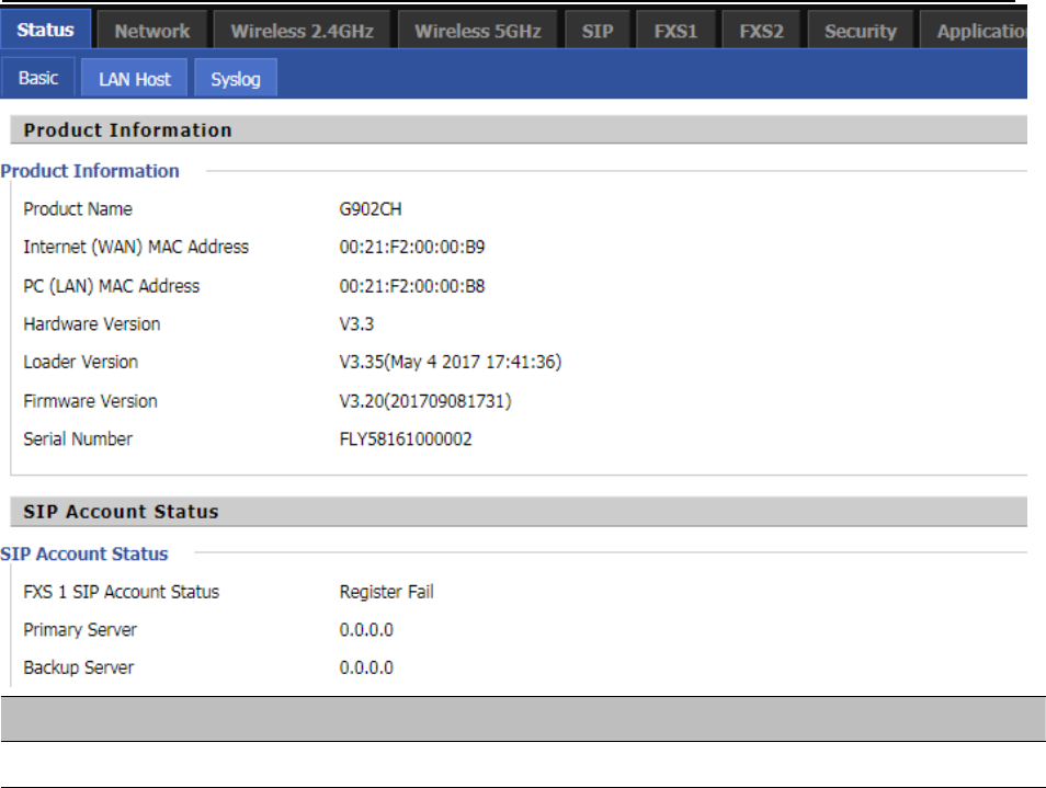
Viewing the Registration Status
Table 11 Registration status
Procedure
To view the SIP account status of device, open the Status webpage and view the value of registration statu
s.
Chapter 2 Basic Settings
28
Making a Call
Calling phone or extension numbers
To make a phone or extension number call:
•
Both ATA and the other VoIP device (i.e., another ATA or other SIP products) must have public IP
addresses, or
•
Both ATA and the other VoIP device (i.e., another ATA or other SIP products) are on the same LAN using
private or public IP addresses, or
•
Both ATA and the other VoIP device (i.e., another ATA or other SIP products) can be connected through a
router using a public or private IP addresses.
To make a call, first pick up the analog phone or turn on the speakerphone on the analog phone, input the IP
address directly, end with #.
Direct IP calls
Direct IP calling allows two phones, that is, an ATA with an analog phone and another VoIP Device, to talk to
each other without a SIP proxy. VoIP calls can be made between two phones if:
•
Both ATA and the other VoIP device (i.e., another ATA or other SIP products) have public IP addresses, or
•
Both ATA and the other VoIP device (i.e., another ATA or other SIP products) are on the same LAN using
private or public IP addresses, or
•
Both ATA and the other VoIP device (i.e., another ATA or other SIP products) can be connected through a
router using public or private IP addresses.
To make a direct IP call, first pick up the analog phone or turn on the speakerphone on the analog phone,
Input the IP address directly, with the end “#”.
Call Hold
While in conversation, pressing the “*77” to put the remote end on hold, then you will hear the dial tone and
the remote party will hear hold tone at the same time.
Pressing the “*77” again to release the previously hold state and resume the bi-directional media.
Blind Transfer
Assume that call party A and party B are in conversation. Party A wants to Blind Transfer B to C:
Party A dials “*78” to get a dial tone, then dials party C’s number, and then press immediately key # (or wait
for 4 seconds) to dial out.
A can hang up.
Chapter 2 Basic Settings
29
Attended Transfer
AssumethatcallpartyAandBareinaconversation.AwantstoAttendTransferBto C:
Party A dials “*77” to hold the party B, when hear the dial tone, A dials C’s number, then party A and party
C are in conversation.
Party A dials “*78” to transfer to C, then B and C now in conversation.
If the transfer is not completed successfully, then A and B are in conversation again.
Conference
Assume that call party A and B are in a conversation. A wants to add C to the conference:
Party A dials “*77” to hold the party B, when hear the dial tone, A dial C’s number, then party A and party C
are in conversation.
Party A dials “*88” to add C, then A and B, for conference.

Chapter 3 Web Interface
30
Chapter 3 Web Interface
This chapter guides users to execute advanced (full) configuration through admin mode operation. This
chapter covers:
•
Login
•
Status
•
Network and Security
•
Wireless
•
SIP
•
FXS1
•
Security
•
Application
•
Administration
•
Management
•
System Log
•
Logout
•
Reboot
Chapter 3 Web Interface
31
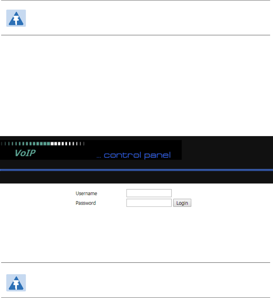
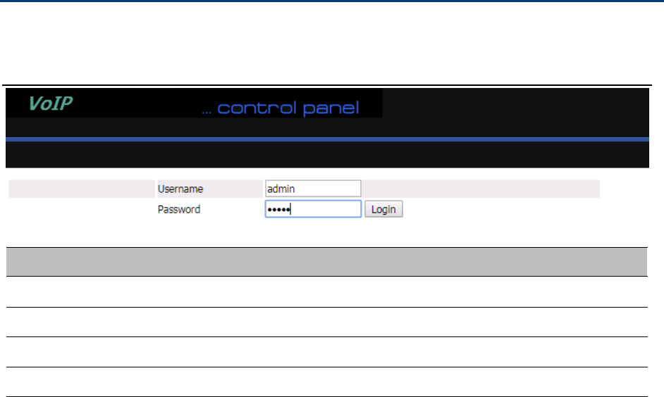
Login
Table 12 Login details
Procedure
1. Connect the LAN port of the router to your PC an Ethernet cable
2. Open a web browser on your PC and type http://192.168.1.1.
3. Enter Username admin and Password admin.
4. Click Login
Chapter 3 Web Interface
32
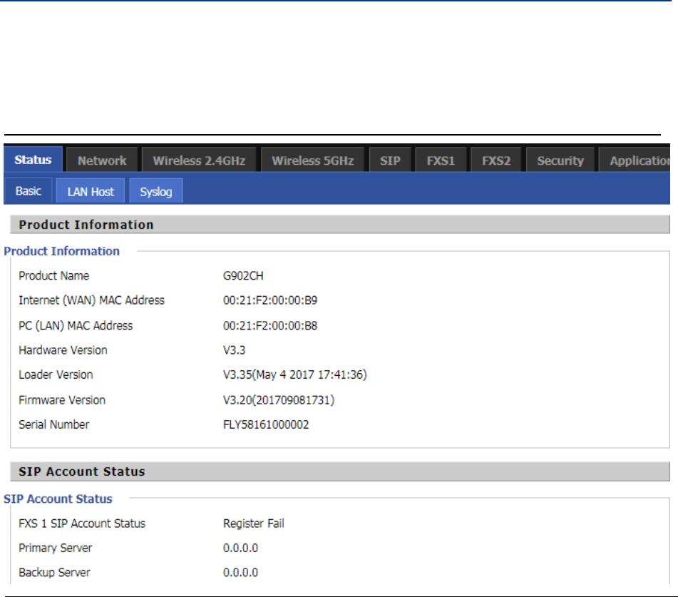
Status
This webpage shows the status information about the Product, Network, SIP Account Status, FXS Port Status,
Network Status,Wireless Info and System Status
Table 13 Status
Chapter 3 Web Interface
33
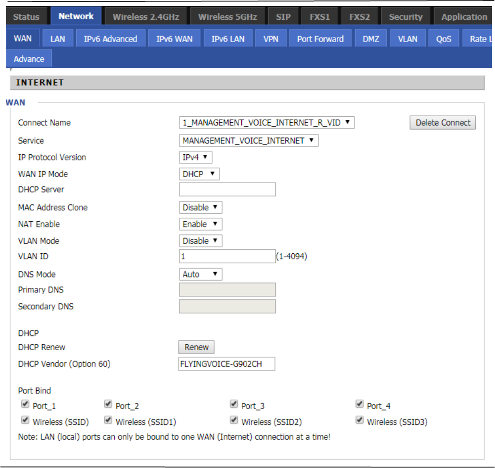
Network and Security
You can configure the WAN port, LAN port, DDNS, Multi WAN, DMZ, MAC Clone, Port Forward and other
parameters in this section of the web management interface.
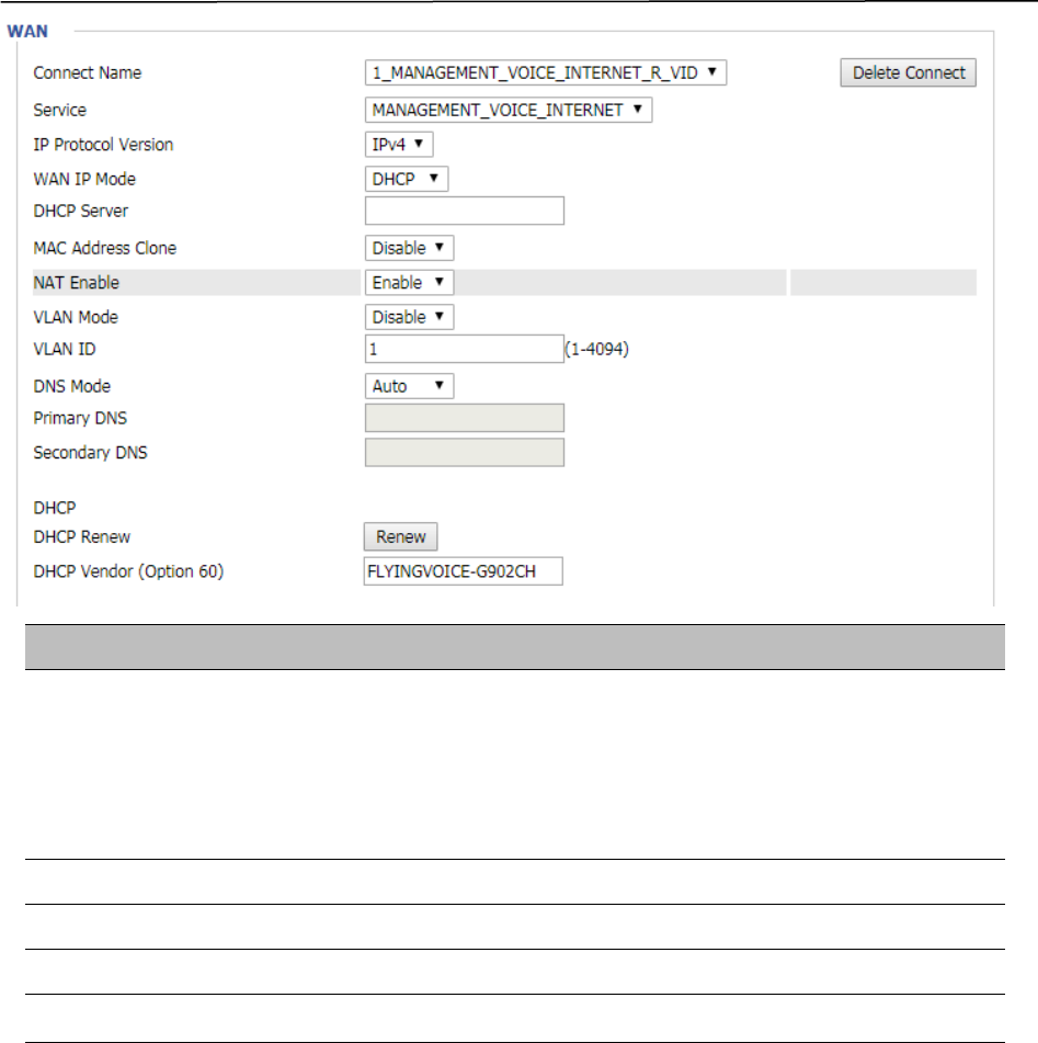
WAN
This page allows you to set WAN configuration with different modes. Use the Connection Type drop
down list to choose one WAN mode and then the corresponding page will be displayed.
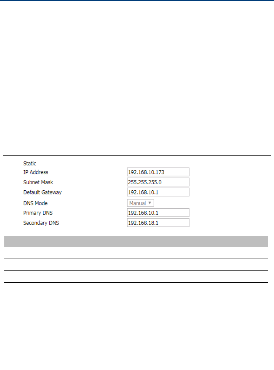
Static IP
This configuration may be utilized when a user receives a fixed public IP address or a public subnet,
namely multiple public IP addresses from the Internet providers. In most cases, a Cable service provider
will offer a fixed public IP, while a DSL service provider will offer a public subnet. If you have a public
subnet, you can assign an IP address to the WAN interface.
Table 14 Internet
Field Name Descripti
IP Address The IP address of Internet port
Subnet Mask The subnet mask of Internet port
Default Gateway The default gateway of Internet port
DNS Mode
Select DNS mode, options are Auto and Manual:
1.
When DNS mode is Auto, the device under LAN port will
automatically obtain the preferred DNS and alternate DNS.
2.
When DNS mode is Manual, the user manually configures the
preferred DNS and alternate DNS information
Primary DNS Address The primary DNS of Internet port
Secondary DNS Address The secondary DNS of Internet port
Chapter 3 Web Interface
34
DHCP
The Router has a built-in DHCP server that assigns private IP address to each local client.
The DHCP feature allows to the router to obtain an IP address automatically from a DHCP server. In this case, it is
not necessary to assign an IP address to the client manually.
Table 15 DHCP
Field Name Description
DNS Mode
Select DNS mode, options are Auto and Manual:
When DNS mode is Auto, the device under LAN port will automaticall
y
obtain the preferred DNS and alternate DNS.
When DNS mode is Manual, the user should manually configure th
e
Primary DNS Address Primary DNS of Internet port.
Secondary DNS Address Secondary DNS of Internet port.
DHCP Renew Refresh the DHCP IP address
DHCP Vendor (Option60) Specify the DHCP Vendor field. Display the vendor and product name.
Chapter 3 Web Interface
35
PPPoE
PPPoE stands for Point-to-Point Protocol over Ethernet. It relies on two widely accepted standards: PPP and
Ethernet. It connects users through an Ethernet to the Internet with a common broadband medium, such as a
single DSL line, wireless device or cable modem. All the users over the Ethernet can share a common
connection.
PPPoE is used for most of DSL modem users. All local users can share one PPPoE connection for accessing the
Internet. Your service provider will provide you information about user name, password, and authentication
mode.
Table 16 PPPoE
Field Name Description
PPPoE Account Enter a valid user name provided by the ISP
PPPoE Password
Enter a valid password provided by the ISP. The password can contain specia
l
characters and allowed special characters are $, +, *, #, @ and ! For example, th
e
password can be entered as #net123@IT!$+*.
Chapter 3 Web Interface
36
Confirm Password Enter your PPPoE password again
Service Name Enter a service name for PPPoE authentication.
If it is left emply, the service name is auto detected.
Operation Mode Select the mode of operation, options are Keep Alive, On Demand and Manual:
When the mode is Keep Alive, the user sets the 'keep alive redial period' values
range from 0 to 3600s, the default setting is 5 minutes;
When the mode is On Demand, the user sets the 'on demand idle time' value in the
range of 0-60 minutes, the default setting is 5 minutes;
When the mode is Manual, there are no additional settings to configure
Keep Alive Redial Set the interval to send Keep Alive messaging
PPPoE Account Assign a valid user name provided by the ISP
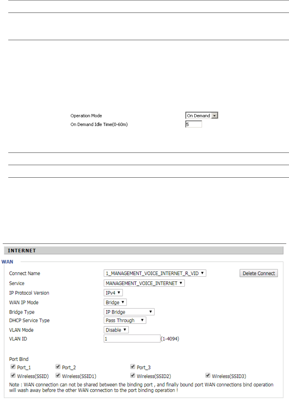
Bridge Mode
Bridge Mode under Multi WAN is different with traditional bridge setting. Bridge mode employs no IP addressing
and the device operates as a bridge between the WAN port and the LAN port. Route Connection has to be built to
give IP address to local service on device.
Table 17 Bridge Mode

Chapter 3 Web Interface
37
Field Name Descripti
Bridge Type
IP Bridge Allow all Ethernet packets to pass. PC can connect to upper network directly.
PPPoE Bridge Only Allow PPPoE packets pass. PC needs PPPoE dial-up software.
Hardware IP Bridge Packets pass through hardware switch with wired speed. Does not support
wireless port binding
DHCP Service Type
Pass Through DHCP packets can be forwarded between WAN and LAN, DHCP server in
gateway will not allocate IP to clients of LAN port.
DHCP Snooping When gateway forwards DHCP packets form LAN to WAN it will add
option82 to DHCP packet, and it will remove option82 when forwarding DHCP
packet from the WAN interface to the LAN interface. Local DHCP service will not
allocate IP to clients of LAN port.
Local Service Gateway will not forward DHCP packets between LAN and WAN, it also blocks
DHCP packets from the WAN port. Clients connected to the LAN port can get IP
from DHCP server run in gateway.
VLAN Mode
Disable The WAN interface is untagged. LAN is untagged.
Enable The WAN interface is tagged. LAN is untagged.
Trunk Only valid in bridge mode. All ports, including WAN and LAN, belong to this
VLAN Id and all ports are tagged with this VLAN id. Tagged packets can pass
through WAN and LAN.
VLAN ID Set the VLAN ID.
802.1p Set the priority of VLAN, Options are 0~7.
Note
Multiple WAN connections may be created with the same VLAN ID
Chapter 3 Web Interface
38
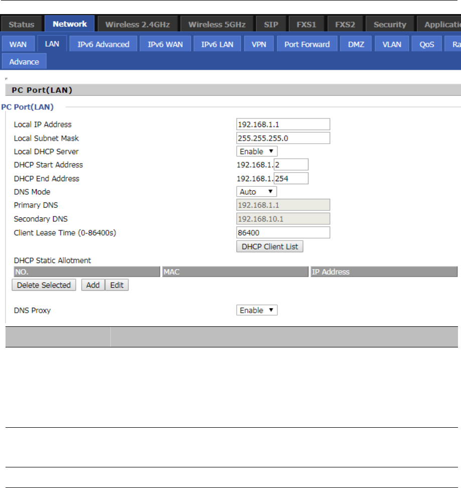
LAN
LAN Port
NAT translates the packets from public IP address to local IP address to forward packets to the proper
destination.
Table 18 LAN port
Field Name Description
IP Address Enter the IP address of the router on the local area network. All the IP
addresses of the computers which are in the router’s LAN must be in the
same network segment with this address, and the default gateway of the
computers must be this IP address. (The default is 192.168.11.1).
Local Subnet Mask Enter the subnet mask to determine the size of the network (default is
255.255.255.0/24).
Local DHCP Server Enable/Disable Local DHCP Server.

Chapter 3 Web Interface
39
DHCP Start Address Enter a valid IP address as a starting IP address of the DHCP server, and if the
router’s LAN IP address is 192.168.11.1, starting IP address can be
192.168.11.2 or greater, but should be less than the ending IP address.
DHCP End Address Enter a valid IP address as an end IP address of the DHCP server.
DNS Mode Select DNS mode, options are Auto and Manual:
When DNS mode is Auto, the device under LAN port will automatically obtains
the preferred DNS and alternate DNS.
When DNS mode is Manual, the user should manually configure the preferred
DNS and alternate DNS.
Primary DNS Enter the preferred DNS address.
Secondary DNS Enter the secondary DNS address.
Client Lease Time This option defines how long the address will be assigned to the computer
within the network. In that period, the server does not assign the IP address to
the other computer.
DNS Proxy Enable or disable; If enabled, the device will forward the DNS request of LAN-
side network to the WAN side network.
VPN
The router supports VPN connections with PPTP-based VPN servers.
Table 19 VPN
Chapter 3 Web Interface
40
Field Name Description
VPN Enable Enable/Disable VPN. If the VPN is enabled, user can select PPTP and L2TP mode
VPN.
Initial Service IP Enter VPN server IP address.
User Name Enter authentication username.
Password Enter authentication password.
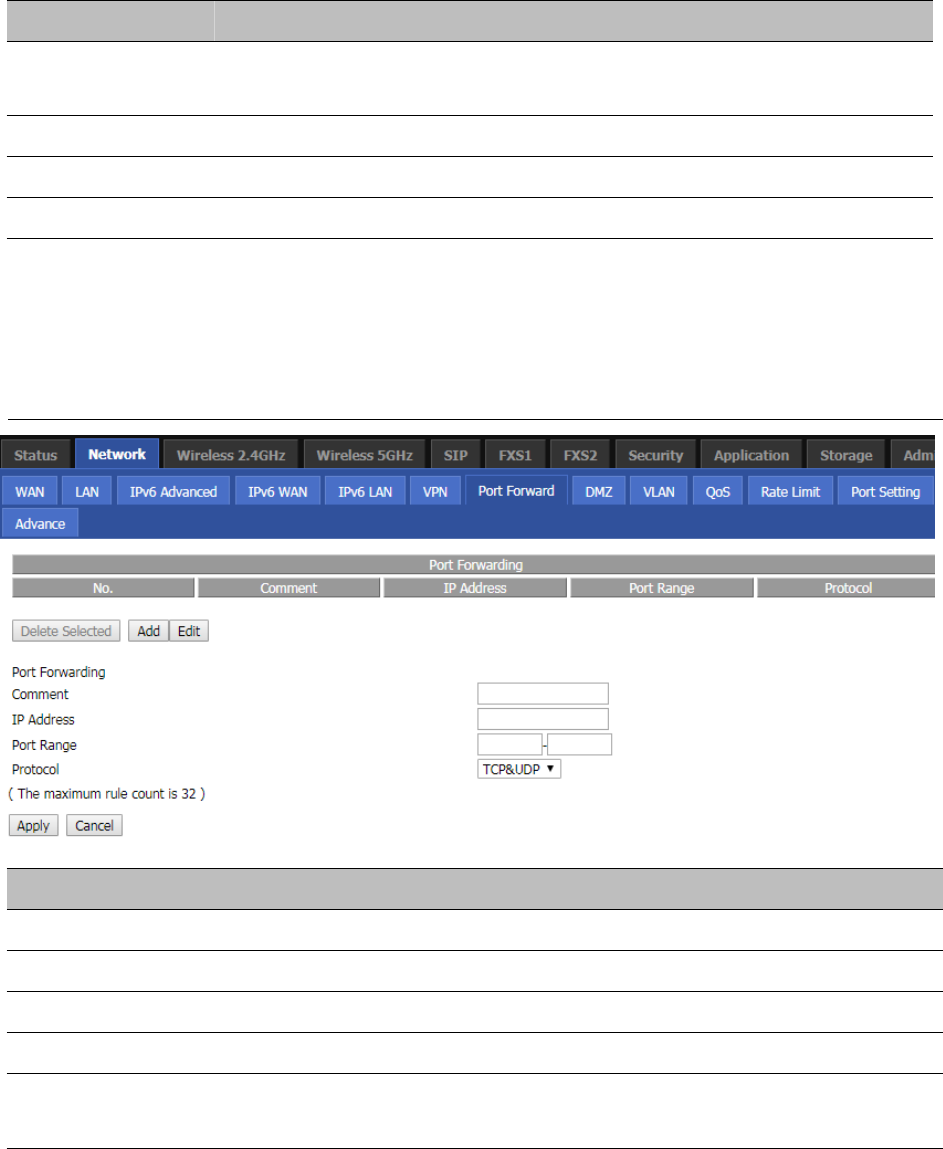
Port Forward
Table 20 Port Forward
Field Name Description
Comment Sets the name of a port mapping rule or comment
IP Address The IP address of devices under the LAN port.
Port Range Set the port range for the devices under the LAN port. (1-65535)
Protocol You can select TCP, UDP, TCP & UDP three cases
Apply/Cancel After finish configurations, click apply, the number will be generated under NO. List;
click Cancel to if you do not want to make the changes.
Chapter 3 Web Interface
41
Table 21 Virtual Servers
Field Name Description
Comment To set up a virtual server notes
IP Address Virtual server IP address
Public Port Public port of virtual server
Private Port Private port of virtual servers ports
Protocol You can select from TCP, UDP, and TCP&UDP.
Apply/Cancel After finish configurations, click apply, the number will be generated under NO. List;
click Cancel to if you do not want to make the changes.
DMZ
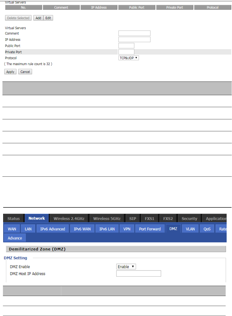
Table 22 DMZ
Field Name Description
DMZ Enable Enable/Disable DMZ.
DMZ Host IP Address Enter the private IP address of the DMZ host.
Chapter 3 Web Interface
42
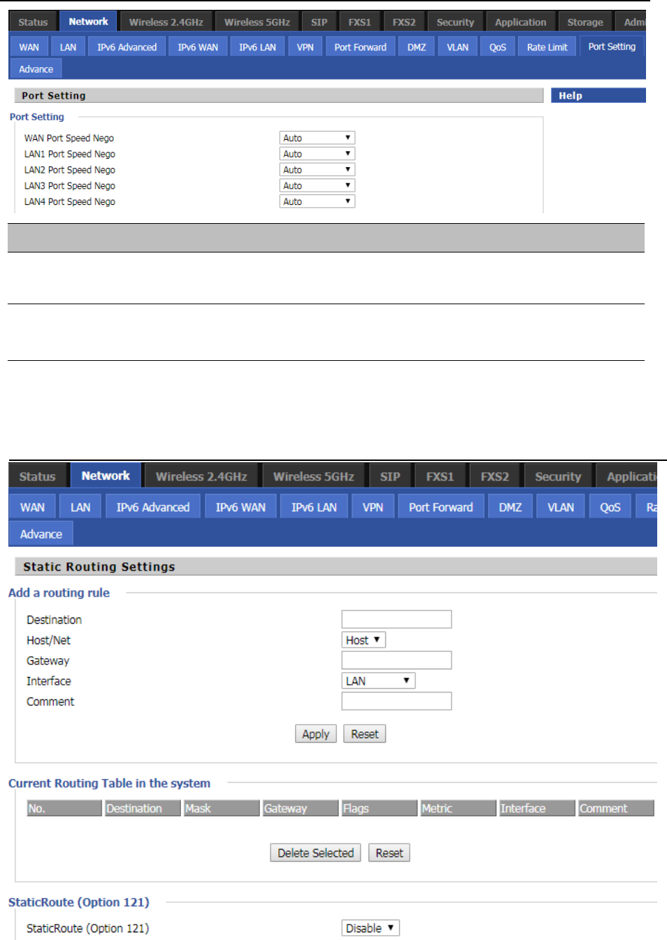
Port Setting
Table 23 P
ort setting
Field Name Description
WAN Port speed Nego Auto-negotiation, options are Auto, 100M full, 100M half-duplex, 10M half
and full.
LAN1~LAN3 Port Speed
Nego
Auto-negotiation, options are Auto, 100M full, 100M half, 10M half and
10M full.
Routing
Table 24 Routing
Chapter 3 Web Interface
43
Field Name Description
Destination Destination address
Host/Net Both Host and Net selection
Gateway Gateway IP address
Interface LAN/WAN/Custom three options, and add the corresponding address
Comment Comment
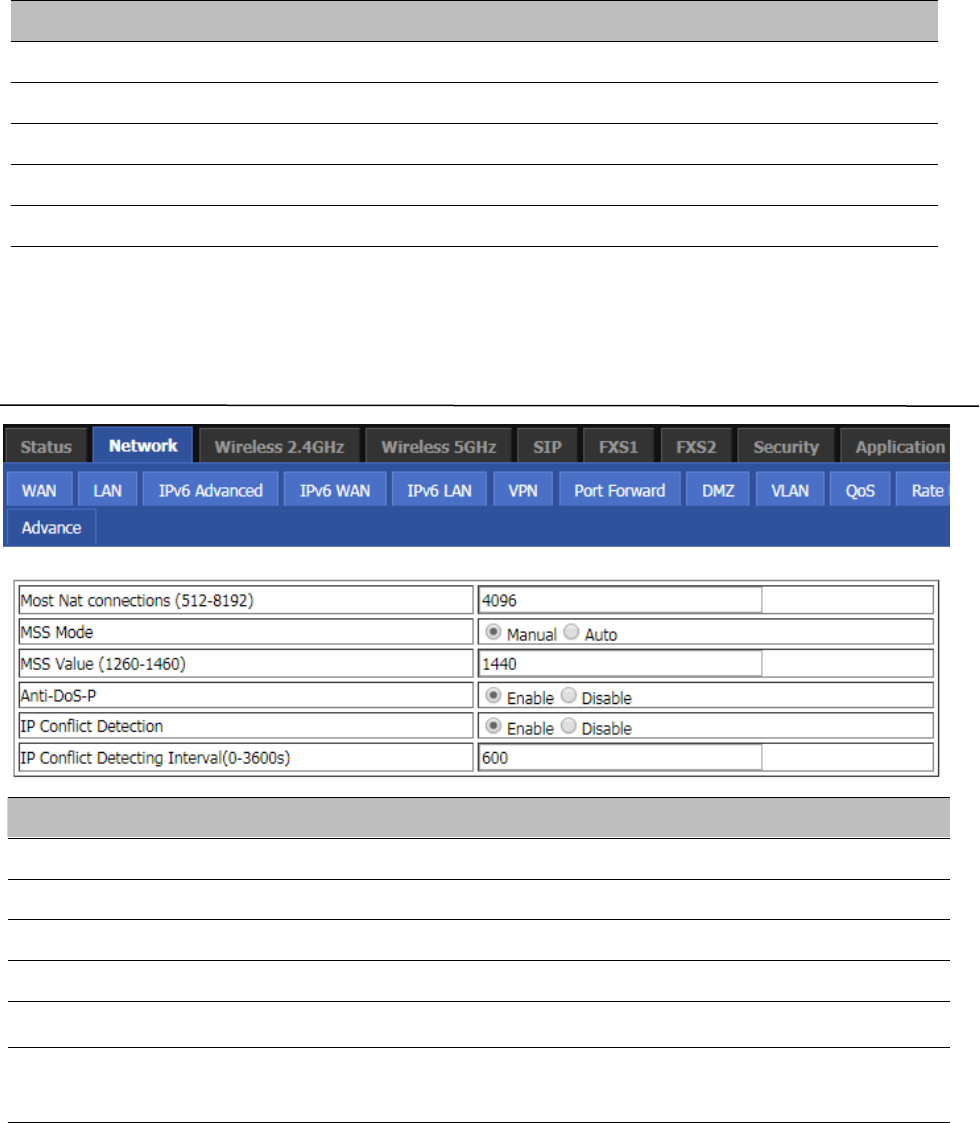
Advance
Table 25 Advance
Field Name Description
Most Nat connections The largest value which the FWR8401 can provide
Mss Mode Choose Mss Mode from Manual and Auto
Mss Value Set the value of TCP
AntiDos-p You can choose to enable or prohibit
IP conflict detection Select enable if enabled, phone IP conflict will have tips or prohibit;
IP conflict Detecting
Interval
Detect IP address conflicts of the time interval
Chapter 3 Web Interface
44
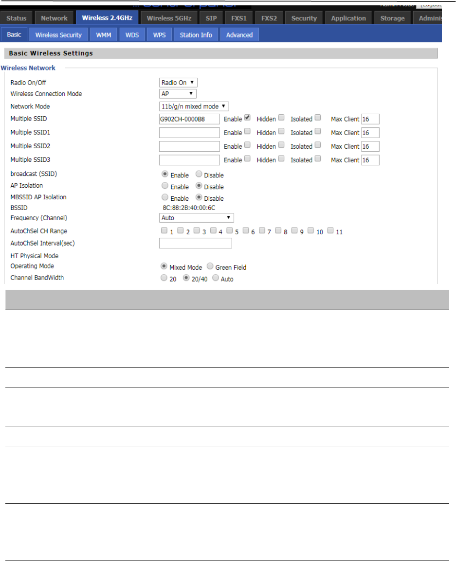
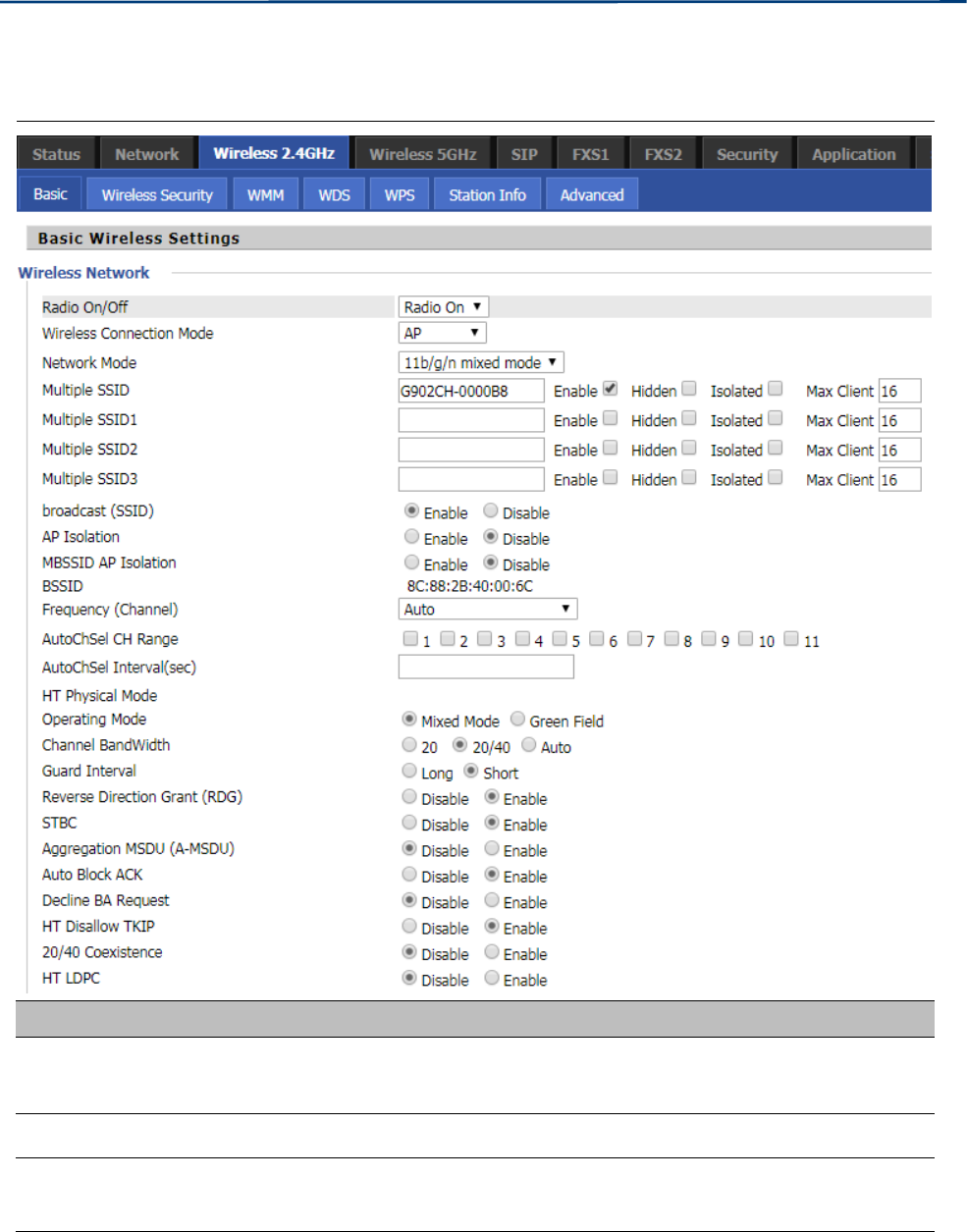
Wireless 2.4GHz
Basic
Table 26 Basic
Field Name Description
Radio on/off Select “Radio off” to disable wireless.
Select “Radio on” to enable wireless.
Wireless connection mode According to the wireless client type, select one of these modes. Default is AP
Network Mode Choose one network mode from the drop down list. Default is 11b/g/n mixed
mode

Chapter 3 Web Interface
45
SSID It is the basic identity of wireless LAN. SSID can be any alphanumeric or a
combination of special characters. It will appear in the wireless network access
list.
Multiple SSID1~SSID3 The device supports 4 SSIDs.
Hidden After the item is checked, the SSID is no longer displayed in the search for the
Wi-Fi wireless network connection list
Broadcast(SSID) After initial State opening, the device broadcasts the SSID of the router to
wireless network
AP Isolation If AP isolation is enabled, the clients of the AP cannot access each other
MBSSID AP Isolation AP isolation among the devices which are not belong to this AP and along to,
when the option is enabled, the devices which do not belong to this AP cannot
access the devices which are within the AP.
BSSID A group of wireless stations and a WLAN access point (AP) consists of a basic
access device (BSS), each computer in the BSS must be configured with the
same BSSID, that is, the wireless AP logo
Frequency (Channel) You can select Auto Select and channel 1/2/3/4/5/6/7/8/9/10/11.
HT Physical Mode
Operating
Mode
Mixed Mode: In this mode, the previous wireless card can recognize and
connect to the Pre-N AP, but the throughput will be affected
Green Field: high throughput can be achieved, but it will affect backward
compatibility, and security of the system
Channel Bandwidth Select channel bandwidth, default is 20 MHz and 20/40 MHz.
Guard Interval The default is automatic, in order to achieve good BER performance, you must
set the appropriate guard interval
Reverse Dirction Grant
(RDG)
Enabled: Devices on the WLAN are able to transmit to each other without
requiring an additional contention-based request to transfer (i.e. devices are
able to transmit to another device on the network during TXOP)
Disabled: Devices on the WLAN must make a request for transmit when
communicating with another device on the network
STBC Space-time Block Code

Chapter 3 Web Interface
46
Enabled: Multiple copies of signals are transmitted to increase the chance of
successful delivery
Aggregation MSDU (A-
MSDU)
Enabled: Allows the device to aggregate multiple Ethernet frames into a single
802.11n, thereby improving the ratio of frame data to frame overhead
Disabled: No frame aggregation is employed at the router
Auto Block Ack
Enabled: Multiple frames are acknowledged together using a single Block
Acknowledgement frame.
Disabled: Auto block acknowledgement is not used by the device – use this
configuration when low throughput/connectivity issues are experienced by
Decline BA Request Enabled: Disallow block acknowledgement requests from devices Disabled:
Allow block acknowledgement requests from devices
HT Disallow TKIP
Enabled: Disallow the use of Temporal Key Integrity Protocol for connected
devices
Disabled: Allow the use of Temporal Key Integrity Protocol for connected
devices
HT LDPC Enabled: Enable Low-Density Parity Check mechanism for increasing chance of
successful delivery in challenging wireless environments
Disabled: Disable Low-Density Parity Check mechanism
Chapter 3 Web Interface
47
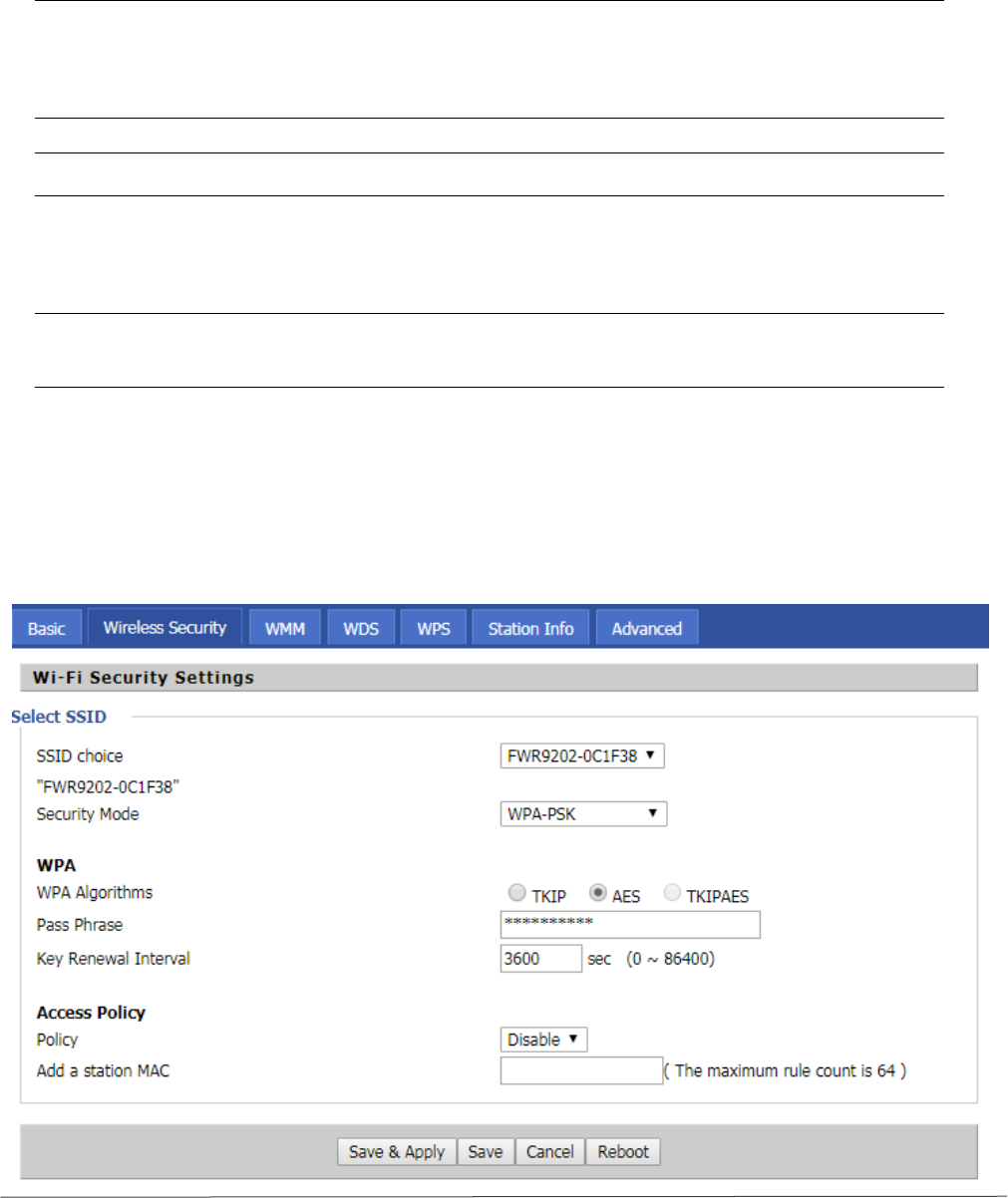
Wireless Security
Table 27 Wireless security
Field Name Description
SSID Choice Choose one SSID from SSID, Multiple SSID1, Multiple SSID2 and Multiple SSID3.
Security Mode
Select an appropriate encryption mode to improve the security and privacy of your
wireless data packets.Each encryption mode will bring out different web page and ask
you to offer additional configuration.
User can configure the corresponding parameters. Here are some common encryption methods:
OPENWEP:A handshake way of WEP encryption, encryption via the WEP key:
Table 28 WiFI Security Setting

Chapter 3 Web Interface
48
Field Name Description
Security Mode This is used to select one of the 4 WEP keys, key settings on the clients should be the
same with this when connecting.
WEP Keys Set the WEP key. A-64 key need 10 Hex characters or 5 ASCII characters; choose A-
128 key need 26 Hex characters or 13 ASCII characters.
WEP represents Wired Equivalent Privacy, which is a basic encryption method.
WPA-PSK, the router will use WPA way which is based on the shared key-based .
Table 29 WPA-PSK
Field Name Description
WPA Algorithms This item is used to select the encryption of wireless home gateway
algorithms, options are TKIP, AES and TKIPAES.
Pass Phrase Setting up WPA-PSK security password.
Key Renewal Interval Set the key scheduled update cycle, default is 3600s.
Chapter 3 Web Interface
49
WPAPSKWPA2PSK
m
anner is consistent with WPA2PSK settings:
Table 30 WPAPSKWPA2PSK
Field Name Description
WPA Algorithms
The home gateway is used to select the wireless security encryption
algorithm options are TKIP, AES, TKIP / AES. 11N mode does not
support TKIP algorithms.
Pass Phrase Set WPA-PSK/WPA2-PSK security code
Key Renewal Interval Set the key scheduled update cycle, default is 3600s
Wireless Access Policy:
Table 31 Wireless Access Policy
Field Name Description
Access policy Wireless access control is used to allow or prohibit the specified client to access to
your wireless network based on the MAC address.
WPA-PSK/WPA2-PSK WPA/WPA2 security type is actually a simplified version,
which is based on the WPA shared key mode, higher security setting is also
relatively simple, suitable for ordinary home users and small businesses.
Chapter 3 Web Interface
50
Policy Disable : Prohibition: wireless access control policy. Allow: only allow the clients in
the list to access.
Rejected: block the clients in the list to access.
Add a station MAC Enter the MAC address of the clients which you want to allow or prohibit
Example: Prohibit the device whose wireless network card MAC address is 00:1F: D0: 62: BA:FF’s to access
the wireless network, and allow other computers to access the network.Implementation: As shown, the
Policy is Reject, add 00:1F: D0: 62: BA: FF to the MAC, click Save and reboot the device settings to take
effect.
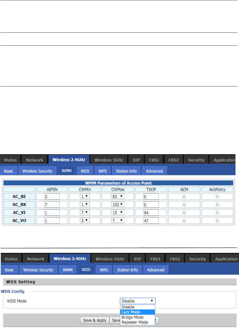
WMM
WMM (Wi-Fi Multi-Media) is the QoS certificate of Wi-Fi Alliance (WFA). This provides you to
configure the parameters of wireless multimedia; WMM allows wireless communication to
define a priority according to the home gateway type. To make WMM effective, the wireless
clients must also support WMM.
Table 32 WMM
WDS
Table 33 WDS
Chapter 3 Web Interface
51
Description
WDS stands for Wireless Distribution System, enabling WDS access points to be interconnected to expand
a wireless network.
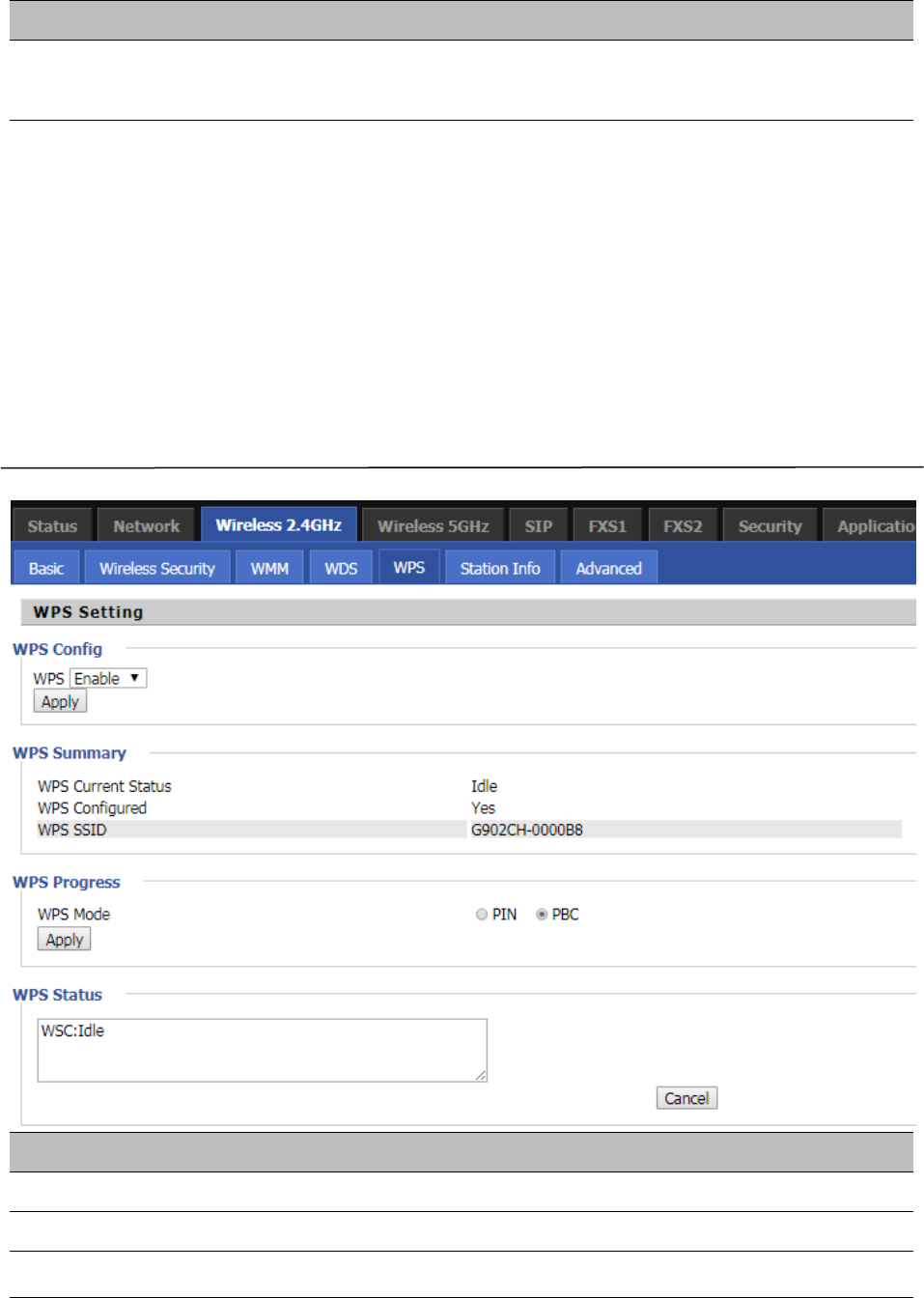
WPS
WPS (Wi-Fi Protected Setup) provides easy procedure to make network connection between wireless
station and wireless access point with the encryption of WPA and WPA2.
It is the simplest way to build connection between wireless network clients and wireless access point. Users
do not need to select any encryption mode and type any long encryption passphrase to setup a wireless
client every time. The only requirement is for the user to press the WPS button on the wireless client, and
WPS will connect for client and router automatically.
Table 34 WPS
Field Name Description
WPS Config
WPS Enable/Disable WPS function
WPS Summary
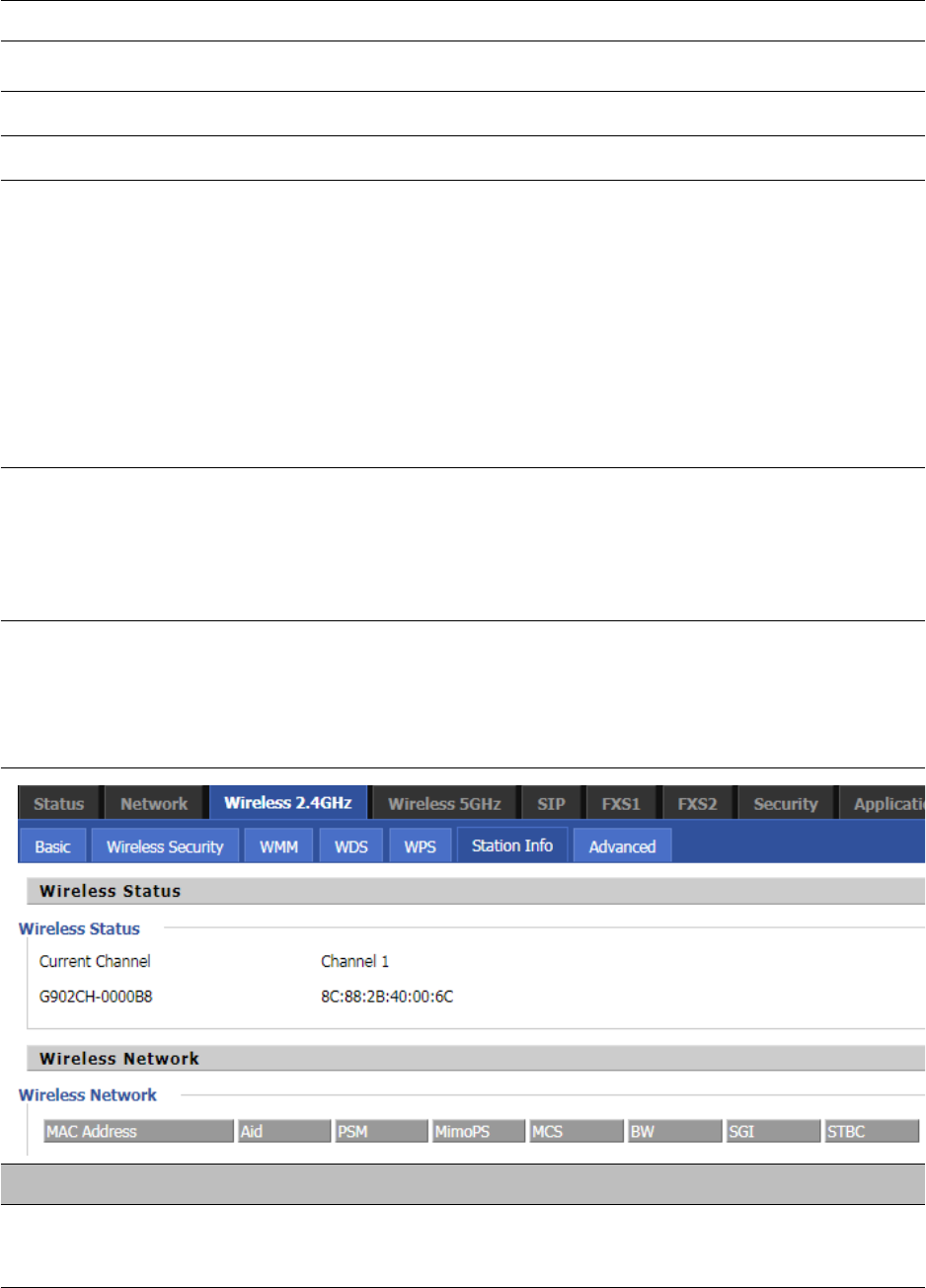
Chapter 3 Web Interface
52
WPS Current Status Display the current status of WPS
WPS Configured Display the configure the status information of WPS
WPS SSID Display WPS SSID
WPS Progress
WPS Mode PIN:Enter the PIN code of the wireless device which accesses to this LAN in the
following option, and press apply. Then router begins to send signals, turn on the PIN
accessing method on the clients, and then it can access the wireless AP automatically.
PBC:There are two ways to start PBC mode, user can press the PBC button directly on
the device, or select PBC mode on the software and apply. Users can activate WPS
connection in WPS mode through these two methods, only when the clients choose
PBC access, the clients can connect the AP automatically.
WPS Status WPS shows status in three ways:
WSC: Idle
WSC: Start WSC process (begin to send messages)
WSC: Success; this means clients have accessed the AP successfully
Station Info
Table 35 Station info
Description
This page displays information about the current registered clients’ connections including operating MAC
address and operating statistics.
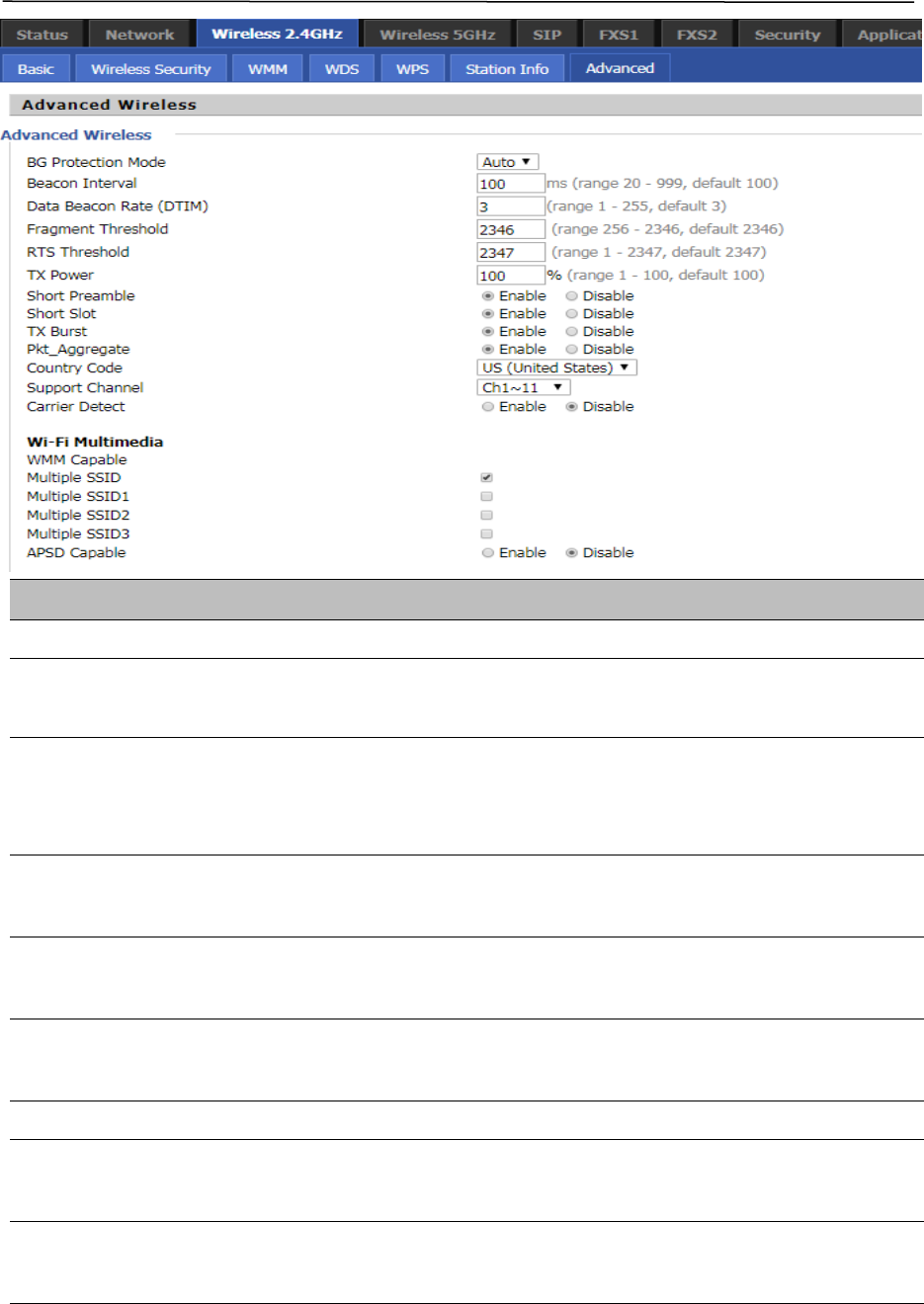
Chapter 3 Web Interface
53
Advanced
Table 36 Advanced
Field Name Description
BG Protection Mode Select G protection mode, options are on, off and automatic.
Beacon Interval The interval of sending a wireless beacon frame, within this range, it will send a
beacon frame for the information of the surrounding radio network.
Data Beacon
Rate(DTIM)
Specify the interval of transmitting the indication message, it is a kind of cut
down operation, and it is used for informing the next client which is going to
receive broadcast multi-cast.
Fragment Threshold Specify the fragment threshold for the packet, when the length of the packet
exceeds this value, the packet is divided.
RTS Threshold Specify the packet RTS threshold, when the packet exceeds this value, the router
will send RTS to the destination site consultation
TX Power Define the transmission power of the current AP, the greater it is, the stronger
the signal is.
Short Preamble Choose enable or disable
Short Slot Enable/Disable short slot. By default it is enabled, it is helpful in improving the
transmission rate of wireless communication.
Tx Burst One of the features of MAC layer, it is used to improve the fairness for
transmitting TCP.
Chapter 3 Web Interface
54
Pkt_Aggregate It is a mechanism that is used to enhance the LAN, in order to ensure that the
home gateway packets are sent to the destination correctly.
Support Channel Choose appropriate channel
Wi-Fi Multimedia (WMM)
WMM Capable Enable/Disable WMM.
APSD Capable Enable/Disable APSD. Once it is enabled, it may affect wireless performance, but
can play a role in energy-saving power
WMM Parameters Press , the webpage will jump to the configuration page
of Wi-Fi multimedia.
Multicast-to-
Unicast Converter
Enable/Disable Multicast-to-Unicast. By default, it is Disabled.
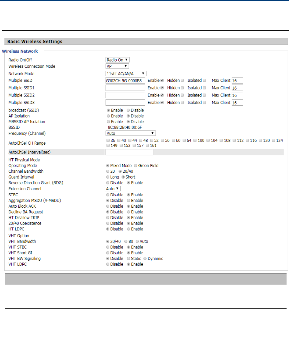
Chapter 3 Web Interface
55
Wireless 5GHz
Basic
Table 37 Basic
Field Name Description
Radio on/off Select “Radio off” to disable wireless.
Select “Radio on” to enable wireless.
Wireless connection
mode
According to the wireless client type, select one of these modes. Default is AP
Network Mode Choose one network mode from the drop down list. Default is 11b/g/n mixe
d
mode

Chapter 3 Web Interface
56
Multiple SSID It is the basic identity of wireless LAN. SSID can be any alphanumeric or a
combination of special characters. It will appear in the wireless network access
list.
Multiple SSID1~SSID3 The device supports 4 SSIDs.
Broadcast(SSID) After initial State opening, the device broadcasts the SSID of the router to
wireless network
AP Isolation If AP isolation is enabled, the clients of the AP cannot access each other
MBSSID AP Isolation AP isolation among the devices which are not belong to this AP and along to,
when the option is enabled, the devices which do not belong to this AP cannot
access the devices which are within the AP.
BSSID A group of wireless stations and a WLAN access point (AP) consists of a basic
access device (BSS), each computer in the BSS must be configured with the
same BSSID, that is, the wireless AP logo
Frequency (Channel) You can select Auto Select and channel 1/2/3/4/5/6/7/8/9/10/11.
Operating Mode Mixed Mode: In this mode, the previous wireless card can recognize and
connect to the Pre-N AP, but the throughput will be affected
Green Field: high throughput can be achieved, but it will affect backward
compatibility, and security of the system
Channel Bandwidth Select channel bandwidth, default is 20 MHz and 20/40 MHz.
Guard Interval The default is automatic, in order to achieve good BER performance, you must
set the appropriate guard interval
Reverse Dirction Grant
(RDG)
Enabled: Devices on the WLAN are able to transmit to each other without
requiring an additional contention-based request to transfer (i.e. devices are
able to transmit to another device on the network during TXOP)
Disabled: Devices on the WLAN must make a request for transmit when
communicating with another device on the network
STBC Space-time Block Code
Enabled: Multiple copies of signals are transmitted to increase the chance of
successful delivery
Disabled: STBC is not employed for signal transmission
Aggregation MSDU (A-
MSDU)
Enabled: Allows the device to aggregate multiple Ethernet frames into a single
802.11n, thereby improving the ratio of frame data to frame overhead
Disabled: No frame aggregation is employed at the router
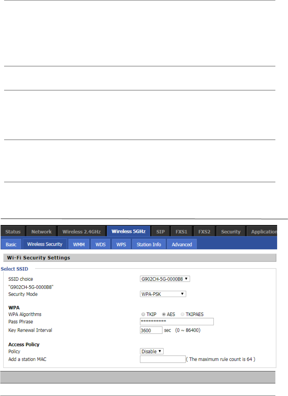
Chapter 3 Web Interface
57
Auto Block Ack
Enabled: Multiple frames are acknowledged together using a single Block
Acknowledgement frame.
Disabled: Auto block acknowledgement is not used by the device – use this
configuration when low throughput/connectivity issues are experienced by
mobile devices
Decline BA Request Enabled: Disallow block acknowledgement requests from devices Disabled:
Allow block acknowledgement requests from devices
HT Disallow TKIP
Enabled: Disallow the use of Temporal Key Integrity Protocol for connected
devices
Disabled: Allow the use of Temporal Key Integrity Protocol for connected
devices
HT LDPC Enabled: Enable Low-Density Parity Check mechanism for increasing chance of
successful delivery in challenging wireless environments
Disabled: Disable Low-Density Parity Check mechanism
Wireless Security
Table 38 Wireless security
Field Name Description
SSID Choice Choose one SSID from SSID, Multiple SSID1, Multiple SSID2 and Multiple SSID3.

Chapter 3 Web Interface
58
Security Mode
Select an appropriate encryption mode to improve the security and privacy of your
wireless data packets.Each encryption mode will bring out different web page and ask
you to offer additional configuration.
Select a different encryption mode, the web interface will be different, user can configure the corresponding
parametersunderthemodeyouselect.Pleasereferto4.4.2section.
WMM
Please refer to 4.4.3 section.
WDS
Please refer to 4.4.4 section.
WPS
Please refer to 4.4.5 section.
Station Info
Please refer to 4.4.6 section.
Advanced
Please refer to 4.4.7 section.
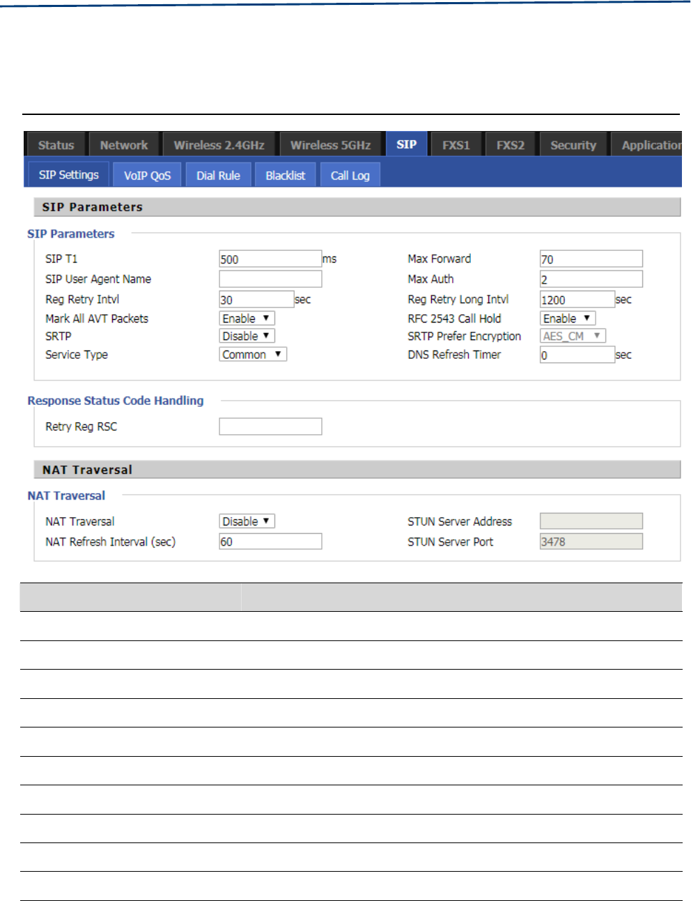
Chapter 3 Web Interface
59
SIP
SIP Settings
Table 39 SIP Settings
Parameters name Description
SIP Parameters
SIP T1 The default value is 500
SIP User Agent Name Enter the SIP User Agent header field
Max Forward Modify the maximum hop value, the default is 70
Max Auth Change the number of authentication failures, the default value is 2
Reg Retry Intvl Registration failed again registration interval, default is 30
Reg Retry Long Intvl Registration failed Register again for the long interval Default 1200
Mark All AVT Packets The default enable is on
RFC 2543 Call Hold The default enable is on
SRTP The default is disabled
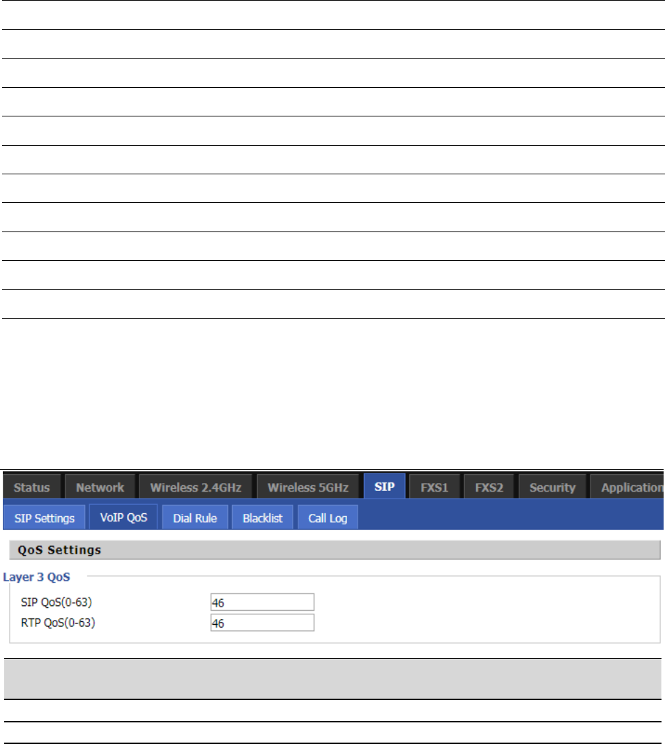
Chapter 3 Web Interface
60
SRTP Prefer Encryption Support for AES_CM and ARIA_CM
Service Type Default general
DNS Refresh Timer Modify the DNS refresh time, the default value of 0
Transport The transmission type defaults to UDP
Response Status Code Handling
Retry Reg RSC Fall in Retry Reg RSC
NAT Traversal
NAT Traversal Whether to enable NAT mode, or select STUN to penetrate
STUN Server Address STUN server IP address
NAT Refresh Interval(sec) Refresh interval
STUN Server Port STUN port, the default is 3478
VoIP QoS
Table 40 VoIP QoS
Configuration can be based on the scene environment to modify the parameters
Parameters name Description
SIP QoS(0-63) Defaults to 46,you can set a range of values is 0~63
RTP QoS(0-63) Defaults to 46,you can set a range of values is 0~63
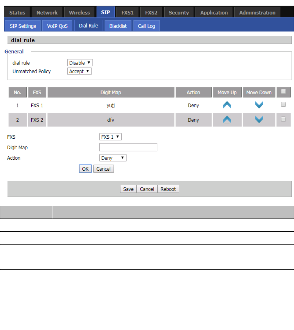
Chapter 3 Web Interface
61
Dial Plan
Table 41 Dial Plan
Field Name Description
Dial Plan Enable/Disable dial plan.
Line Set the line.
Digit Map Enter the sequence used to match input number
The syntactic, please refer to the following Dial Plan Syntactic.
Action Choose the dial plan mode from Deny and Dial Out.
Deny means router will reject the matched number, while Dial Out means router will
dial out the matched number.
Move Up Move the dial plan up the list.
Move Down Move the dial plan down the list.
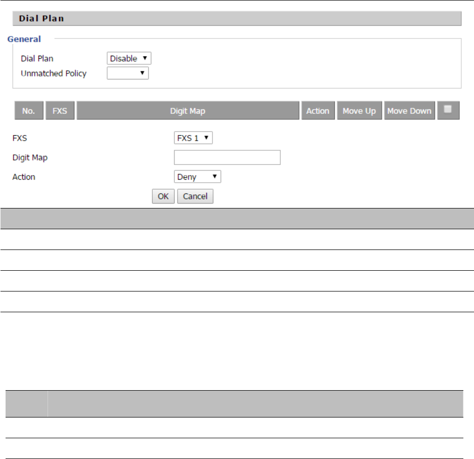
Chapter 3 Web Interface
62
Adding one Dial Plan
Table 42 Adding one dial plan
Description
Step 1. Enable Dial Plan.
Step 2. Click Add button, and the configuration table.
Step 3. Fill in the value of parameters.
Step 4. Press OK button to end configuration.
Dial Plan Syntactic
Table 43 Dial Plan Syntactic
No. String Description
1 0123456789* # Allowedcharacters
2 x Lowercase letter “x” stands for one legal character
3
[sequence]
To match one character form sequence. For example:
[0-9]: match one digit form 0 to 9
[23-5*]: match one character from 2 or 3 or 4 or 5 or *
4
x.
Match to x, xx, xxx, xxxx and so on.
For example:
“01” can be match to “0”,”01”,”011”...”011111...” and so on
5
<dialed:substituted>
Replace dialed with substituted.
For example:
<8:1650>123456:input is “85551212”, output is
“16505551212”
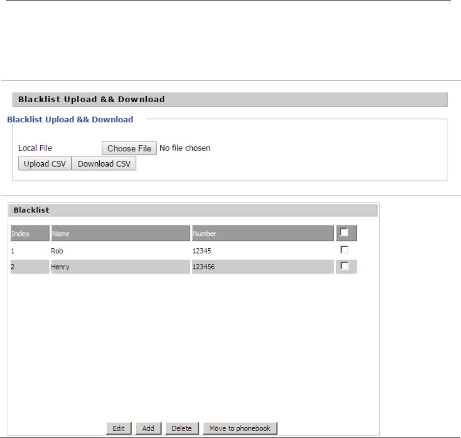
Chapter 3 Web Interface
63
6x,y
Make outside dial tone after dialing “x”, stop until dialing
character “y”
For example:
“9,1xxxxxxxxxx”:the device reports dial tone after inputting
“9”, stops tone until inputting “1”
“9,8,010x”: make outside dial tone after inputting “9”,
stop tone until inputting “0”
7T
Set the delayed time. For example:
“<9:111>T2”: The device will dial out the matched number
“111”after 2 seconds.
Blacklist
In this page, user can upload or download blacklist file, and can add or delete or edit blacklist one by one.
Table 44 Blacklist
Chapter 3 Web Interface
64
Description
Click to select the blacklist file and to upload it to device; Click
to save the blacklist file to your local computer.
Select one contact and click edit to change the information, click delete to delete the contact, click Move
to phonebook to move the contact to phonebook.
Click Add to add one blacklist, enter the name and phone number, click OK to confirm and click cancel to
cancel.
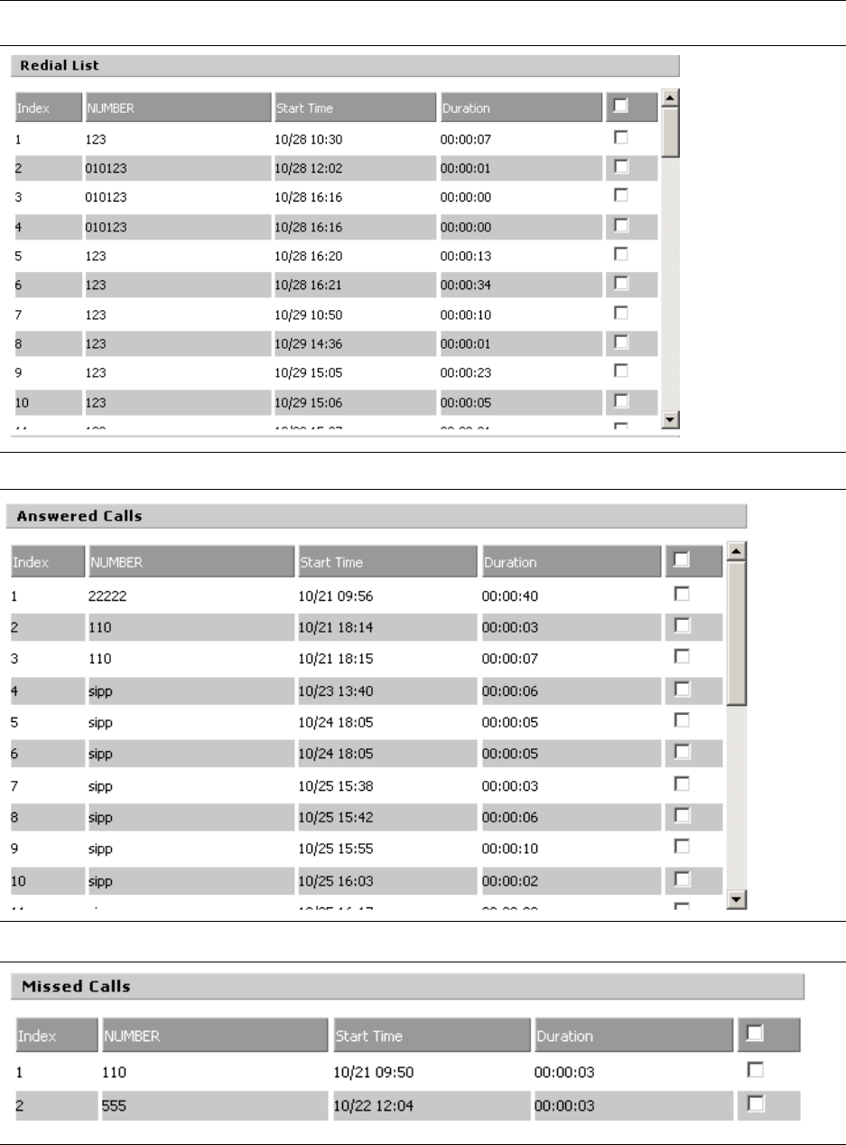
Chapter 3 Web Interface
65
Call Log
To view the call log information such as redial list , answered call and missed call
Table 45 Call log
Redial Calls
Answered Calls
Missed Calls
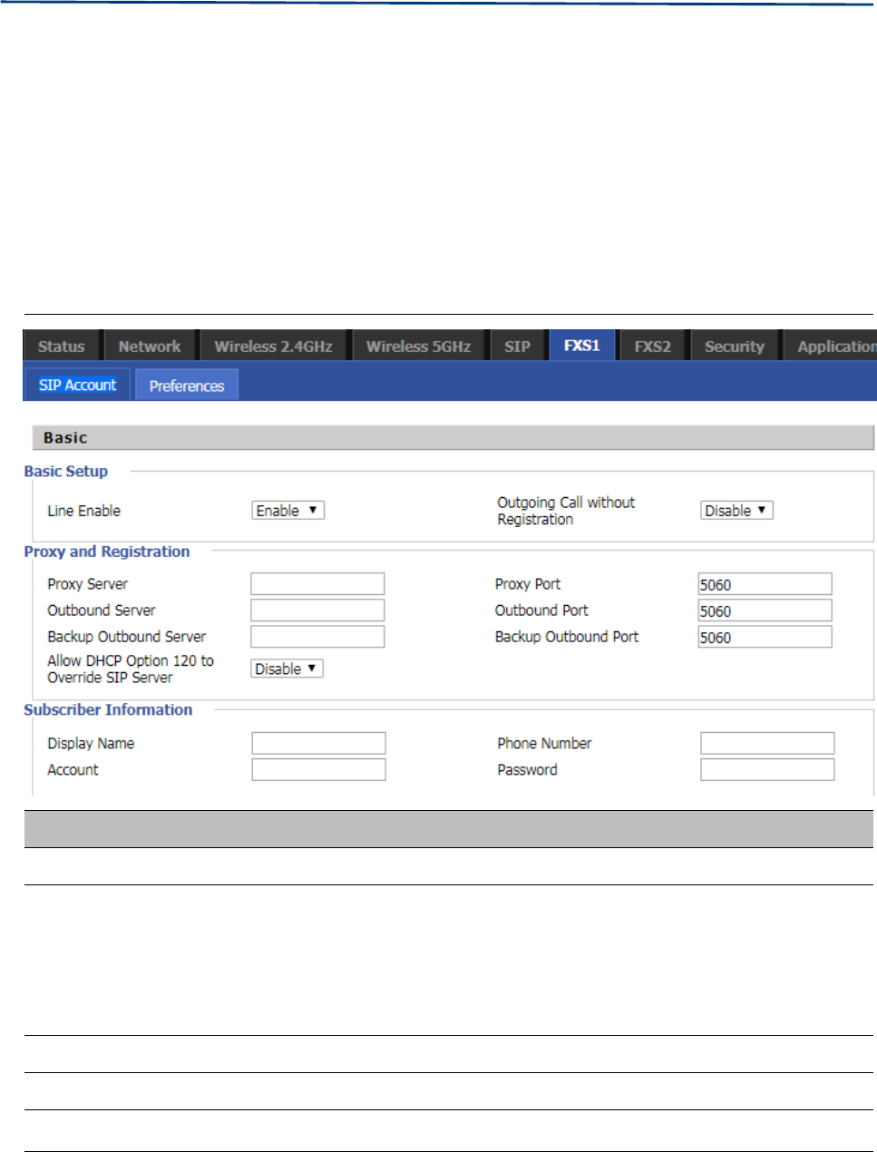
Chapter 3 Web Interface
66
FXS 1
SIP Account
Basic
S
et the basic information provided by your VOIP Service Provider, such as Phone Number, Account,
password, SIP Proxy and others.
Table 46 Line
Field Name Description
Line Enable Enable/Disable the line.
Peer To Peer
Enable/Disable PEER to PEER.
If enabled, SIP-1 will not send register request to SIP server; but in Status/ SIP
Account Status webpage, Status is Registered; lines 1 can dial out, but the
external line number cannot dialed line1.
Proxy Server The IP address or the domain of SIP Server
Outbound Server The IP address or the domain of Outbound Server
Backup Outbound Server The IP address or the domain of Backup Outbound Server
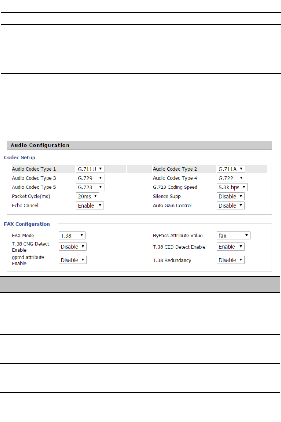
Chapter 3 Web Interface
67
Proxy port SIP Service port, default is 5060
Outbound Port Outbound Proxy’s Service port, default is 5060
Backup Outbound Port Backup Outbound Proxy’s Service port, default is 5060
Display Name The number will be displayed on LCD
Phone Number Enter telephone number provided by SIP Proxy
Account Enter SIP account provided by SIP Proxy
Password Enter SIP password provided by SIP Proxy
Audio Configuration
Table 47 Audio configuration
Field Name Description
Audio Codec Type1 Choose the audio codec type from G.711U, G.711A, G.722, G.729, G.723
Audio Codec Type2 Choose the audio codec type from G.711U, G.711A, G.722, G.729, G.723
Audio Codec Type3 Choose the audio codec type from G.711U, G.711A, G.722, G.729, G.723
Audio Codec Type4 Choose the audio codec type from G.711U, G.711A, G.722, G.729, G.723
Audio Codec Type5 Choose the audio codec type from G.711U, G.711A, G.722, G.729, G.723
G.723 Coding Speed Choose the speed of G.723 from 5.3kbps and 6.3kbps
Packet Cycle The RTP packet cycle time, default is 20ms
Silence Supp Enable/Disable silence support
Echo Cancel Enable/Disable echo cancel. By default, it is enabled
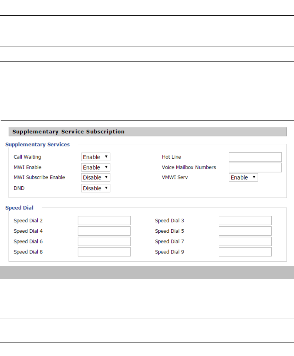
Chapter 3 Web Interface
68
Auto Gain Control Enable/Disable auto gain
T.38 Enable Enable/Disable T.38
T.38 Redundancy Enable/Disable T.38 Redundancy
T.38 CNG Detect Enable Enable/Disable T.38 CNG Detect
gpmd attribute Enable Enable/Disable gpmd attribute
Supplementary Service Subscription
Table 48 Supplementary service
Field Name Description
Call Waiting Enable/Disable Call Waiting
Hot Line Fill in the hotline number,Pickup handset or press hands-free or headset button,
the device will dial out the hotline number automatically
MWI Enable Enable/Disable MWI (message waiting indicate). If the user needs to user voice
mail, please enable this feature
MWI Subscribe Enable Enable/Disable MWI Subscribe
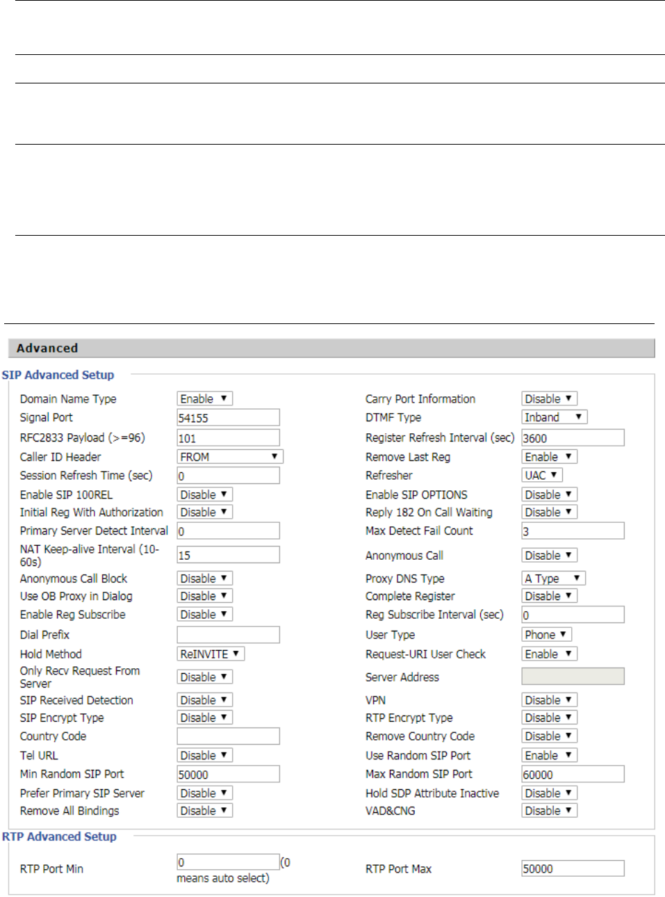
Chapter 3 Web Interface
69
Advanced
Table 49 Advanced
Voice Mailbox
Numbers
Fill in the voice mailbox phone number, Asterisk platform, for example, its default voice
mail is *97
VMWI Serv Enable/Disable VMWI service
DND Enable/Disable DND (do not disturb)
If enable, any phone call cannot arrive at the device; default is disable
Speed Dial
Enter the speed dial phone numbers. Dial *74 to active speed dial function
Then press the speed dial numbers, for example, press 2, phone dials 075526099365
directly

Chapter 3 Web Interface
70
Parameter name Description
Domain Name Type Whether to enable domain name recognition in SIP URIs
Carry Port Information Whether to carry the SIP URI port information
Signal Port The local port number of the SIP protocol
DTMF Type Select the second way of dialing, optional items are In-band,
RFC2833 and SIP Info.
RFC2833 Payload(>=96) The user can use the default settings
Register Refresh Interval(sec) The time interval between two normal registration messages. The
user can use the default settings.
Caller ID Header
When enabled, an unregistered message will be sent before the
registration is disabled, and no unregistered messages will be sent
before registration; should be set according to the different server
requirements
Remove Last Reg Whether to remove the last registration message
Session Refresh Time(sec) The interval between two sessions, the user can use the default
settings
Refresher Select Refresh from UAC and UAS
SIP 100REL Enable
If this option is enabled, the IP phone will send SIP-OPTION to the
server instead of sending Hello messages on a regular basis. The
interval for sending is the parameter set for the "NAT Hold
Interval" parameter.
SIP OPTIONS Enable Whether to open the SIP OPTION function
Initial Reg With Authorization Whether to carry the certification information when registering
Reply 182 On Call Waiting Whether or not to send 182 when the call is waiting
NAT Keep-alive Interval(10-60s) The time interval for sending empty packets
Anonymous Call Whether anonymous calls are enabled
Anonymous Call Block Whether to enable anonymous call blocking
Proxy DNS Type Set the DNS server type, the optional items are Type A, DNS SRV,
and Auto
Use OB Proxy In Dialog Whether the OB agent is used in the conversation
Complete Register Whether to enable full registration
Reg Subscribe Enable
When enabled, the subscription message is sent after the
registration message; the subscription message is not sent when
disabled
Reg Subscribe Interval(sec)
Dial Prefix Dial before prefix
User Type Whether the end user is IP or Phone

Chapter 3 Web Interface
71
Hold Method Call hold is REINVITE or INFO
Request-URI User Check Whether to allow the user to check
Only Recv Request From Server If enabled, will only accept requests from the server, do not accept
other requests
Server Address SIP server address
SIP Received Detection Whether to allow SIP receive detection
VPN Whether to enable VPN
SIP Encrypt Type Whether to allow SIP message encryption
RTP Encrypt Type Whether to allow RTP message encryption
Country Code Country code
Remove Country Code Whether to allow the removal of national codes
Tel URL Whether to open the Tel URL
Use Random SIP Port Whether to use the minimum random port
Min Random SIP Port SIP minimum random port
Max Random SIP Port SIP maximum random port
Prefer Primary SIP Server Whether to enable the preferred primary server
Hold SDP Attribute Inactive Whether to enable the call to keep the inactive attribute
Remove All Bindings
VAD&CNG
RTP Port Min RTP minimum port
RTP Port Max RTP's maximum port
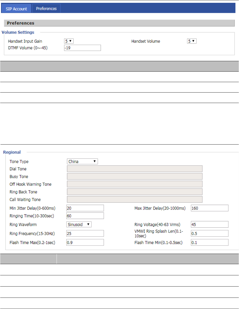
Chapter 3 Web Interface
72
Preferences
Preferences
Table 50 Preferences
Field Name Description
Handset Input Gain Adjust the handset input gain from 0 to 7.
Handset Volume Adjust the output gain from 0 to 7.
DTMF Volume (0~-45) Default is -19, you can set a range of values is 0~ -45
Regional
Table 51 Regional
Field Name Description
Tone Type Choose tone type form China, US, Hong Kong and so on.
Dial Tone Dial Tone
Busy Tone Busy Tone
Off Hook Warning Tone Off Hook warning tone
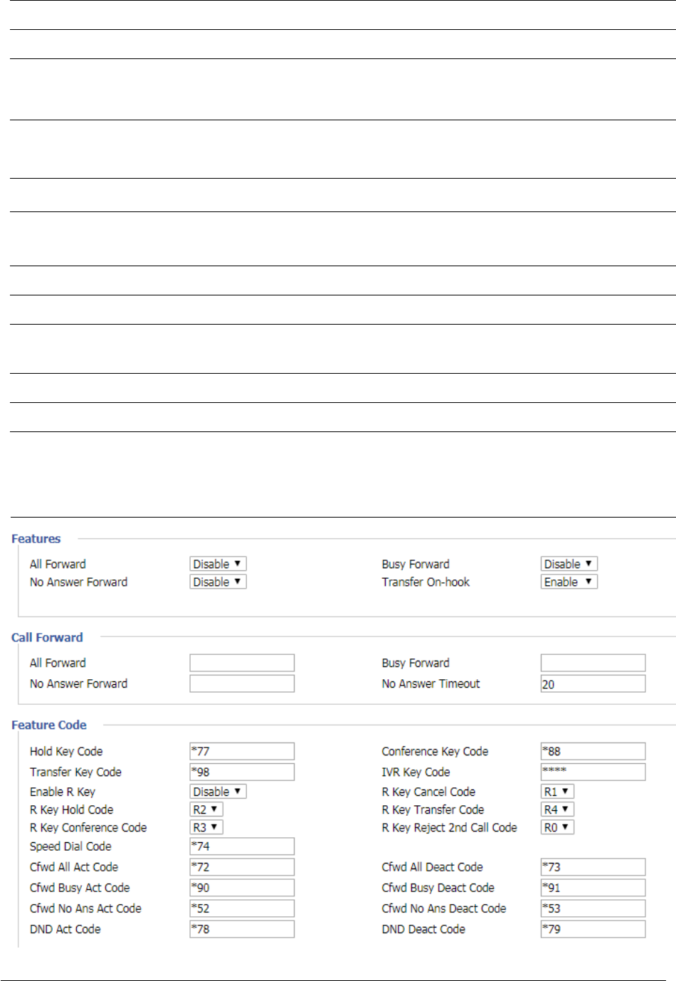
Chapter 3 Web Interface
73
Ring Back Tone Ring back tone
Call Waiting Tone Call waiting tone
Min Jitter Delay The Min value of home gateway’s jitter delay, home gateway is an adaptive jitter
mechanism.
Max Jitter Delay The Max value of home gateway’s jitter delay, home gateway is an adaptive jitter
mechanism.
Ringing Time How long CnPilot Home R190/R200x will ring when there is an incoming call.
Ring Waveform Select regional ring waveform, options are Sinusoid and Trapezoid, the default
Sinusoid.
Ring Voltage Set ringing voltage, the default value is 70
Ring Frequency Set ring frequency, the default value is 25
VMWI Ring Splash
L
e
n
(sec)
Set the VMWI ring splash length, default is 0.5s.
Flash Time Max(sec) Set the Max value of the device’s flash time, the default value is 0.9
Flash Time Min(sec) Set the Min value of the device’s flash time, the default value is 0.1
Features and Call Forward
Table 52 Features and call forward

Chapter 3 Web Interface
74
Field Name Description
Features All Forward Enable/Disable forward all calls
Busy Forward Enable/Disable busy forward.
No Answer Forward Enable/Disable no answer forward.
Call Forward All Forward Set the target phone number for all forward.
The device will forward all calls to the phone number immediately
when there is an incoming call.
Busy Forward The phone number which the calls will be forwarded to when line
is busy.
No Answer Forward The phone number which the call will be forwarded to when
there's no answer.
No Answer Timeout The seconds to delay forwarding calls, if there is no answer at your
phone.
Feature Code Hold key code Call hold signatures, default is *77.
Conference key Signature of the tripartite session, default is *88.
Transfer key code Call forwarding signatures, default is *98.
IVR key code Signatures of the voice menu, default is ****.
R key enable Enable/Disable R key way call features.
R key cancel code Set the R key cancel code, option are ranged from R1 to R9,
default value is R1.
R key hold code Set the R key hold code, options are ranged from R1 to R9, default
value is R2.
R key transfer code Set the R key transfer code, options are ranged from R1 to R9,
default value is R4.
R key conference
code
Set the R key conference code, options are ranged from R1 to R9,
default value is R3.
R Key Reject 2nd
Call Code
Set the R key Reject 2nd Call code, options are ranged from R1 to
R9, default value is R0.
Speed Dial Code Speed dial code, default is *74.
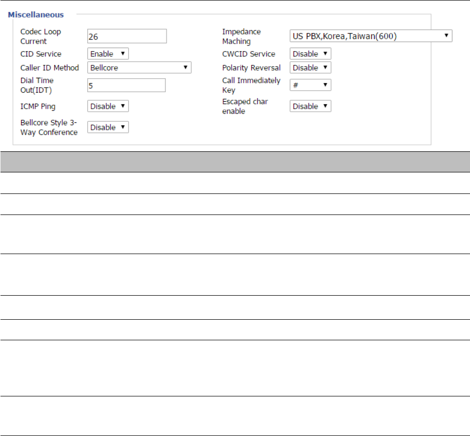
Chapter 3 Web Interface
75
Miscellaneous
Table 53 Miscellaneous
Field Name Description
Codec Loop Current Set off-hook loop current, default is 26
Impedance Maching Set impedance matching, default is US PBX,Korea,Taiwan(600).
CID service Enable/Disable displaying caller ID; If enable, caller ID is displayed when there is an
incoming call or it won’t be displayed. Default is enable.
CWCID Service Enable/Disable CWCID. If enable, the device will display the waiting call’s caller ID,
or it won’t display. Default is disable.
Dial Time Out How long device will sound dial out tone when device dials a number.
Call Immediately Key Choose call immediately key form * or #.
ICMP Ping Enable/Disable ICMP Ping.
If enable this option, home gateway will ping the SIP Server every interval
time, otherwise, It will send “hello” empty packet to the SIP Server.
Escaped char enable Open special character translation function; if enable, when you press the # key, it
will be translated to 23%, when disable, it is just #
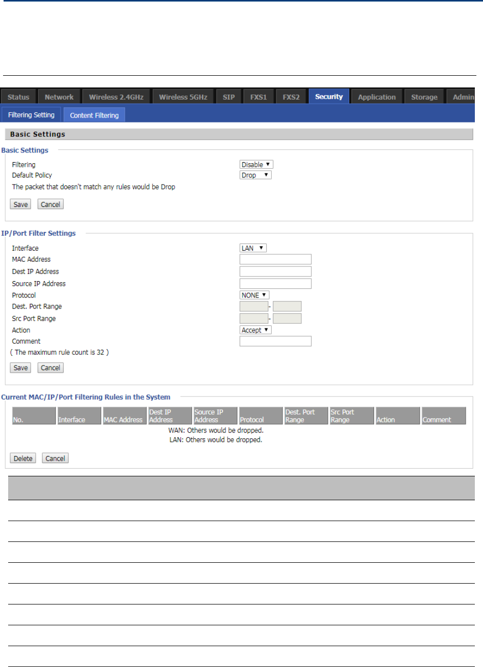
Chapter 3 Web Interface
76
Security
Filtering Setting
Table 54 Filtering Setting
Field Name Description
Filtering If or not enable filter function
Default Policy Choose to give up or accept
Mac address Add the Mac address filtering
Dest IP address Dest IP address
Source IP address Source IP address
Protocol Select a protocol name, support for TCP, UDP and TCP&UDP
Dest. Port Range Destination port ranges
Src Port Range Source port range
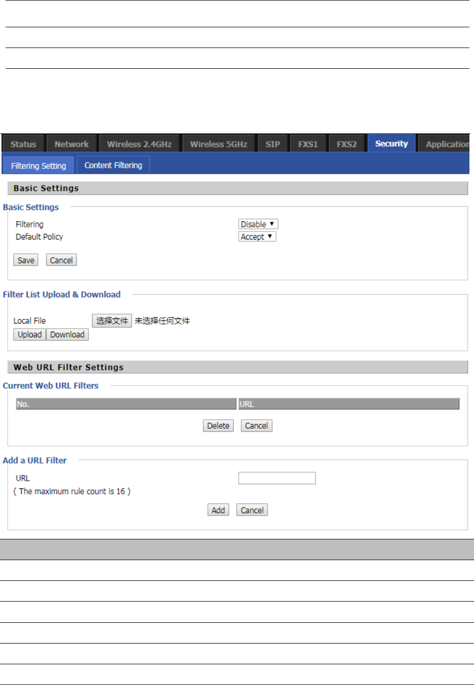
Chapter 3 Web Interface
77
Action You can choose to receive or give up; this should be consistent with the
default policy.
Comment Add callout
Delete Delete selected item
Content Filtering
Table 55 Content Filtering
Field Name Description
Filtering Enable/Disable content Filtering
Default Policy The default policy is to accept or to prohibit filtering rules
Current Webs URL Filters List the URL filtering rules that already existed (blacklist)
Delete/Cancel You can choose to delete or cancel the existing filter rules
Add a URL Filter Add URL filtering rules
Add/Cancel Click adds to add one rule or click cancel

Chapter 3 Web Interface
78
Current Website Host
Filters
List the keywords that already exist (blacklist)
Delete/Cancel You can choose to delete or cancel the existing filter rules the existing keywords
Add a Host Filter Add keywords
Add/Cancel Click the Add or cancel
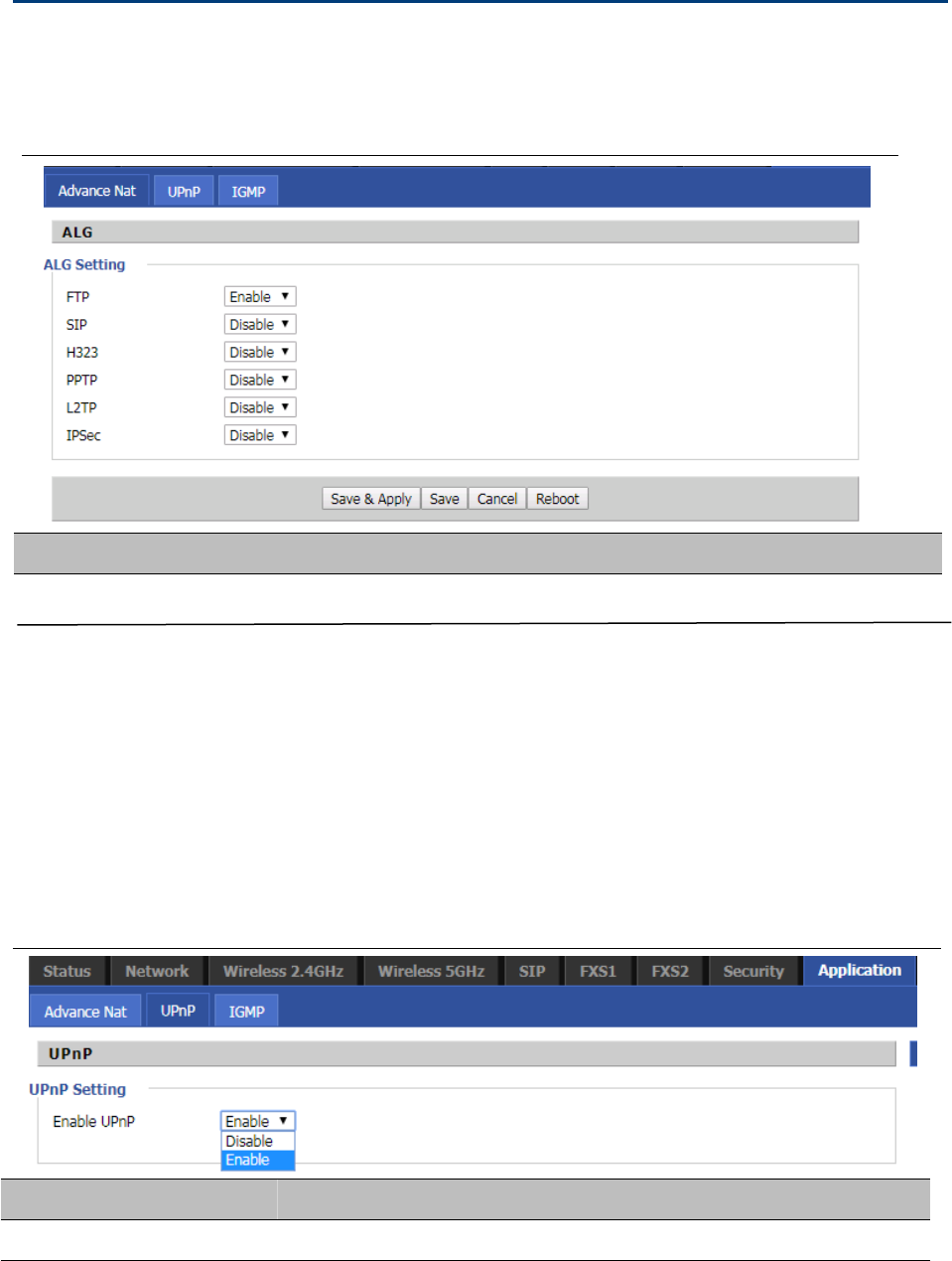
Chapter 3 Web Interface
79
Application
Advance NAT
Table56 advance NAT
Enable/Disable these function(FTP/SIP/H323/PPTP/L2TP/IPSec).
UPnP
U
PnP (Universal Plug and Play) supports zero-configuration networking, and can automatically discover a variety
of networked devices. When UPnP is enabled, the connected device is allowed to access the network, obtain an
IP address, and convey performance information. If the network has a DHCP and DNS server, the connected
device can automatically obtain DHCP and DNS services.
UPnP devices can be automatically added to the network without affecting previously-connected devices.
Table 57 UPnP
Field Name Description
UPnP enable Enable/Disable UPnP function.
Descri
p
tion
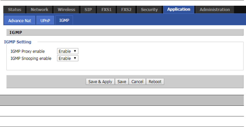
Chapter 3 Web Interface
80
IGMP
Multicast has the ability to send the same data to multiple devices.
IP hosts use IGMP (Internet Group Management Protocol) report multicast group memberships to the
neighboring routers to transmit data, at the same time, the multicast router use IGMP to discover which hosts
belong to the same multicast group.
Table 58 IGMP
Field Name Description
IGMP Proxy enable Enable/Disable IGMP Proxy function.
IGMP Snooping enable enable Enable/Disable IGMP Snooping function.
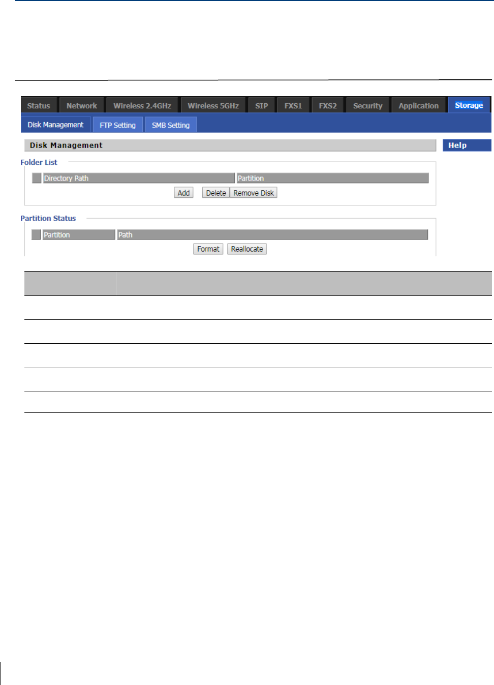
Chapter 3 Web Interface
81
Disk Management
Table 59 Disk Management
Field Name Description
Add Adding files to the USB storage device
Delete Remove the USB storage device file
Remove Disk Transfer files within a USB storage device
Format Format the USB storage device
Re-allocate Resetting the USB storage device
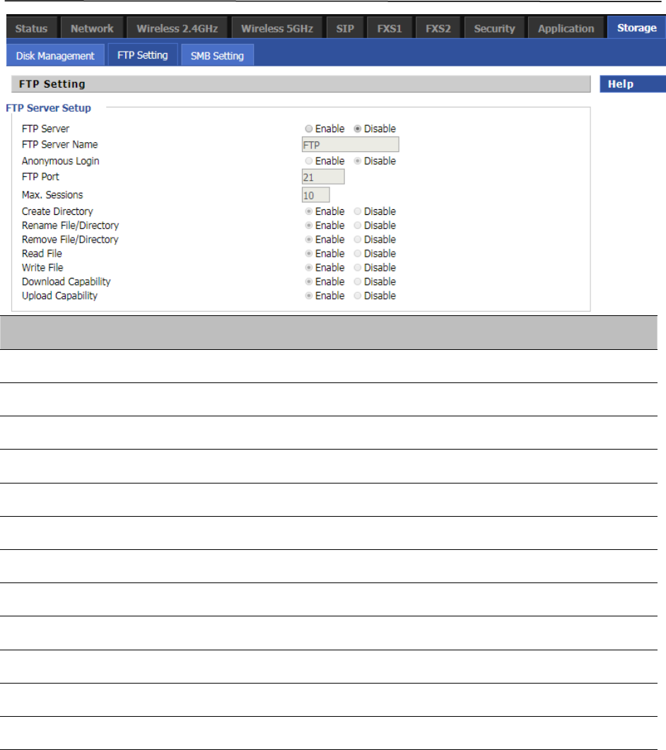
Chapter 3 Web Interface
82
FTP Setting
Table 60 FTP Setting
Field Name Description
FTP Server If or not enable FTP server
FTP Server Name Set the FTP server name
Anonymous Login If or not support anonymous login
FTP Port Set FTP server port number
Max. Sessions Maximum number of connections
Create Directory If or not enable create directory
Rename File/Directory If or not enable rename file/directory
Remove File/Directory If or not enable transfer of files/directories
Read File If or not enable read files
Write File If or not enable write files
Download Capability If or not enable download capability function.
Upload Capability If or not enable upload capability function
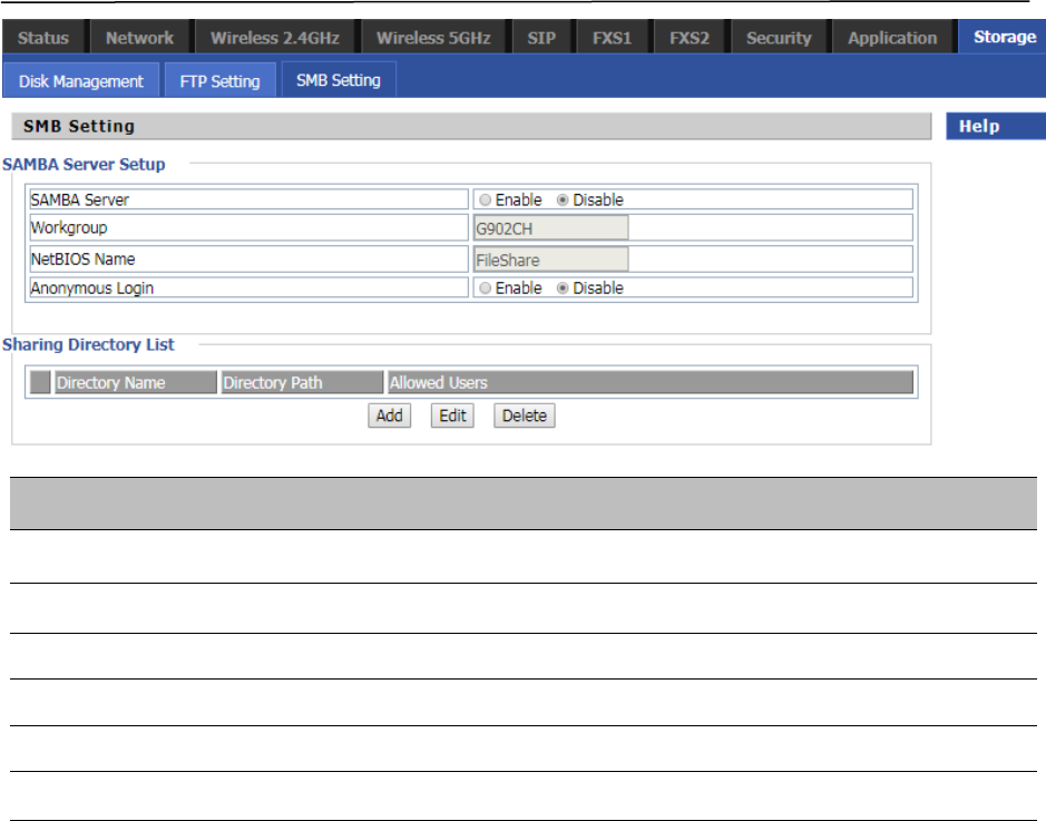
Chapter 3 Web Interface
83
SMB Setting
Table 61 SMB Setting
Field Name Description
SAMBA Server If or not enable SAMBA server
Workgroup Fill in the working group
NetBIOS Name Network basic input/output system name
Add Add a shared file
Edit Edit a shared file
Del Delete a shared file
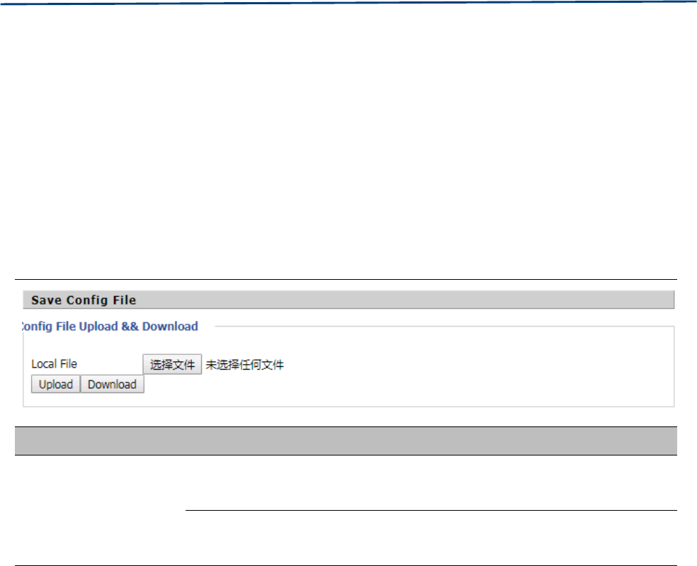
Chapter 3 Web Interface
84
Administration
The user can manage the device in these webpages; you can configure the Time/Date, password, web access,
system log and associated configuration TR069.
Management
Save config file
Table 62 Save Config File
Field Name Description
Config file upload and
download
Upload: click on browse, select file in the local, press the upload button to
begin uploading files
Download: click to download, and then select contains the path to download
the configuration file
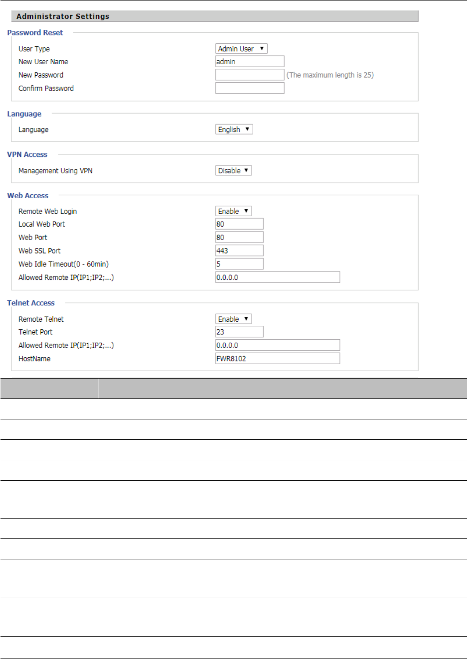
Chapter 3 Web Interface
85
Administrator settings
Table 63 Administrator settings
Field Name Description
User type Choose the user type from admin user and normal user and basic user
New User Name You can modify the user name, set up a new user name
New Password Input the new password
Confirm Password Input the new password again
Language Select the language for the web, the device support Chinese, English, and Spanish
and so on
Remote Web Login Enable/Disable remote Web login
Web Port Set the port value which is used to login from Internet port and PC port, default is 80
Web Idle timeout Set the Web Idle timeout time. The webpage can be logged out after Web Idle
Timeout without any operation
Allowed Remote
IP(IP1,IP2,...)
Set the IP from which a user can login the device remotely
Telnet Port Set the port value which is used to telnet to the device
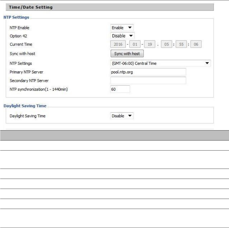
Chapter 3 Web Interface
86
NTP settings
Table 64 NTP settings
Field Name Description
NTP Enable Enable/Disable NTP
Option 42 Enable/Disable DHCP option 42. This option specifies a list of the NTP servers
available to the client by IP address
Current Time Display current time
NTP Settings Setting the Time Zone
Primary NTP Server Primary NTP server's IP address or domain name
Secondary NTP Server Options for NTP server's IP address or domain name
NTP synchronization NTP synchronization cycle, cycle time can be 1 to 1440 minutes in any one, the
default setting is 60 minutes
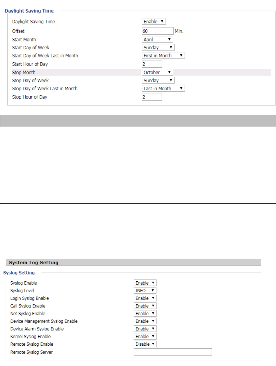
Chapter 3 Web Interface
87
Daylight Saving Time
Table 65 Daylight Saving Time
Procedure
S
tep 1. Enable Daylight Savings Time.
Step 2. Set value of offset for Daylight Savings Time
Step 3: Set starting Month/Week/Day/Hour in Start Month/Start Day of Week Last in Month/Start Day of
Week/Start Hour of Day, analogously set stopping Month/Week/Day/Hour in Stop Month/Stop Day of Week
Last in Month/Stop Day of Week/Stop Hour of Day.
Step 4.Press Saving button to save and press Reboot button to active changes.
System Log Setting
Table 66 System log Setting
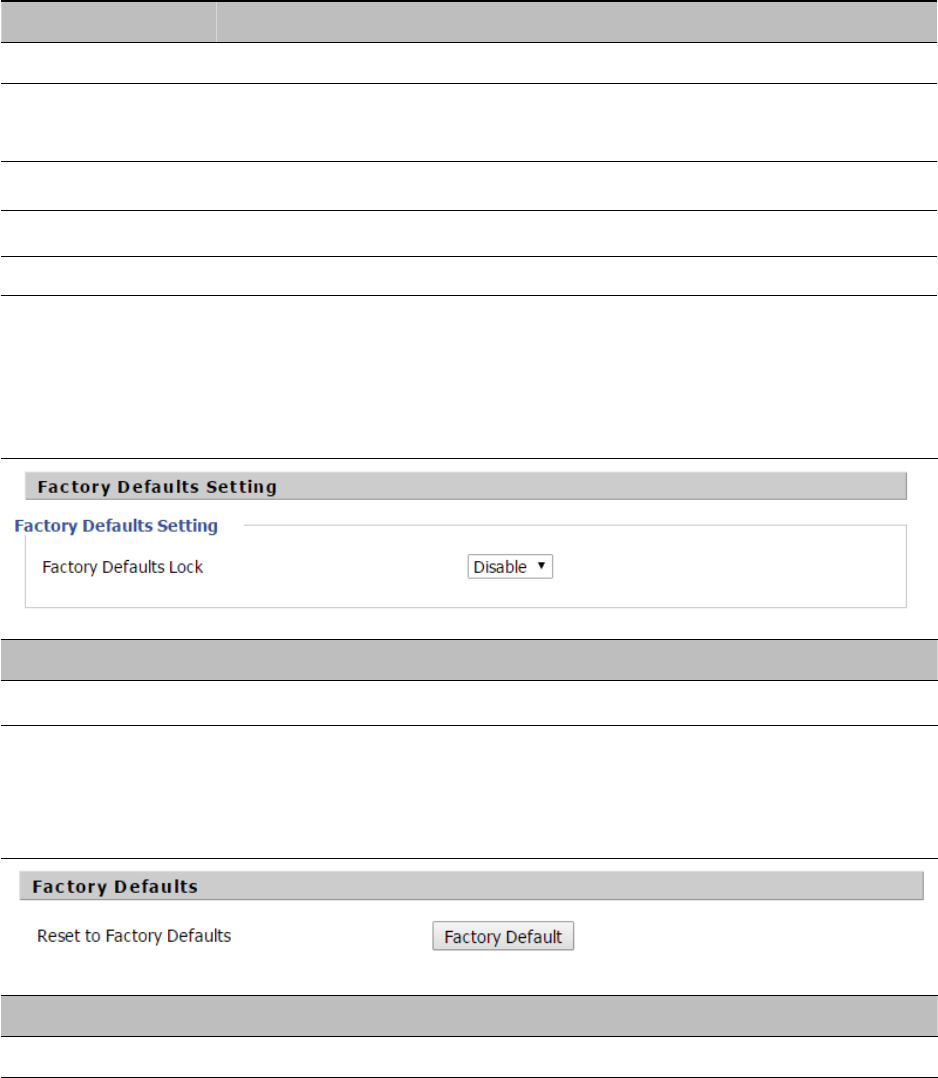
Chapter 3 Web Interface
88
Field Name Description
Syslog Enable Enable/Disable syslog function
Syslog Level Select the system log, there is INFO and Debug two grades, the Debug INFO can
provide more information
Remote Syslog Enable Enable/Disable remote syslog function
Remote Syslog server Add a remote server IP address
Syslog Enable Enable/Disable syslog function
Factory Defaults Setting
Table 67 Factory Defaults Setting
Description
When enabled, the device may not be reset to factory defaults until this parameter is reset to Disable
Factory Defaults
Table 68 Factory Defaults
Description
C
lick Factory Default to restore the residential gateway to factory setting
s
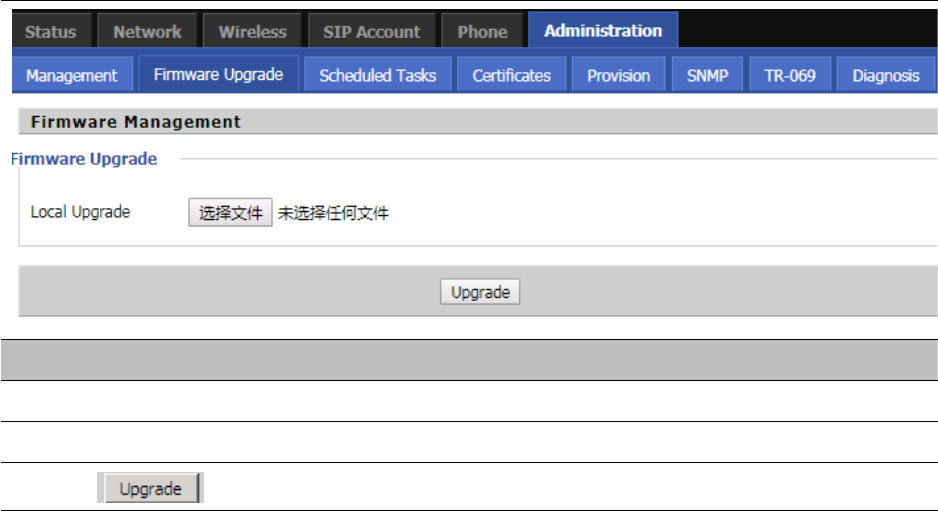
Chapter 3 Web Interface
89
Firmware Upgrade
Table 69 Firmware upgrade
Description
1. Choose upgrade file type from Image File and Dial Rule
2. Press “Browse..” button to browser file
3. Press to start upgrading
Provision
Provisioning allows the router to auto-upgrade and auto-configure devices which support TFTP, HTTP and
HTTPs .
•
Before testing or using TFTP, user should have tftp server and upgrading file and configuring file.
•
Before testing or using HTTP, user should have http server and upgrading file and configuring file.
•
Before testing or using HTTPS, user should have https server and upgrading file and configuring file
and CA Certificate file (should same as https server’s) and Client Certificate file and Private key file
User can upload a CA Certificate file and Client Certificate file and Private Key file in the Security page.
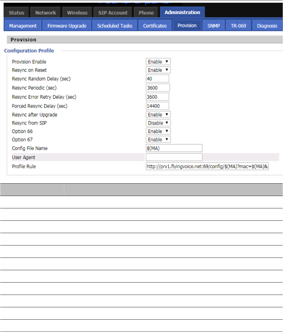
Chapter 3 Web Interface
90
Table 70 Provision
Field Name Description
Provision Enable Enable provision or not.
Resync on Reset Enable resync after restart or not
Resync Random Set the maximum delay for the request of synchronization file. The default is 40
Resync Periodic(sec) If the last resync was failure, The router will retry resync after the “Resync Error
Resync Error Retry Set the periodic time for resync, default is 3600s
Forced Resync If it’s time to resync, but the device is busy now, in this case,the router will wait
Resync After Enable firmware upgrade after resync or not. The default is Enabled
Resync From SIP Enable/Disable resync from SIP
Option 66 It is used for In-house provision mode only. When use TFTP with option 66 to
Config File Name It is used for In-house provision mode only. When use TFTP with option 66 to
Profile Rule URL of profile provision file
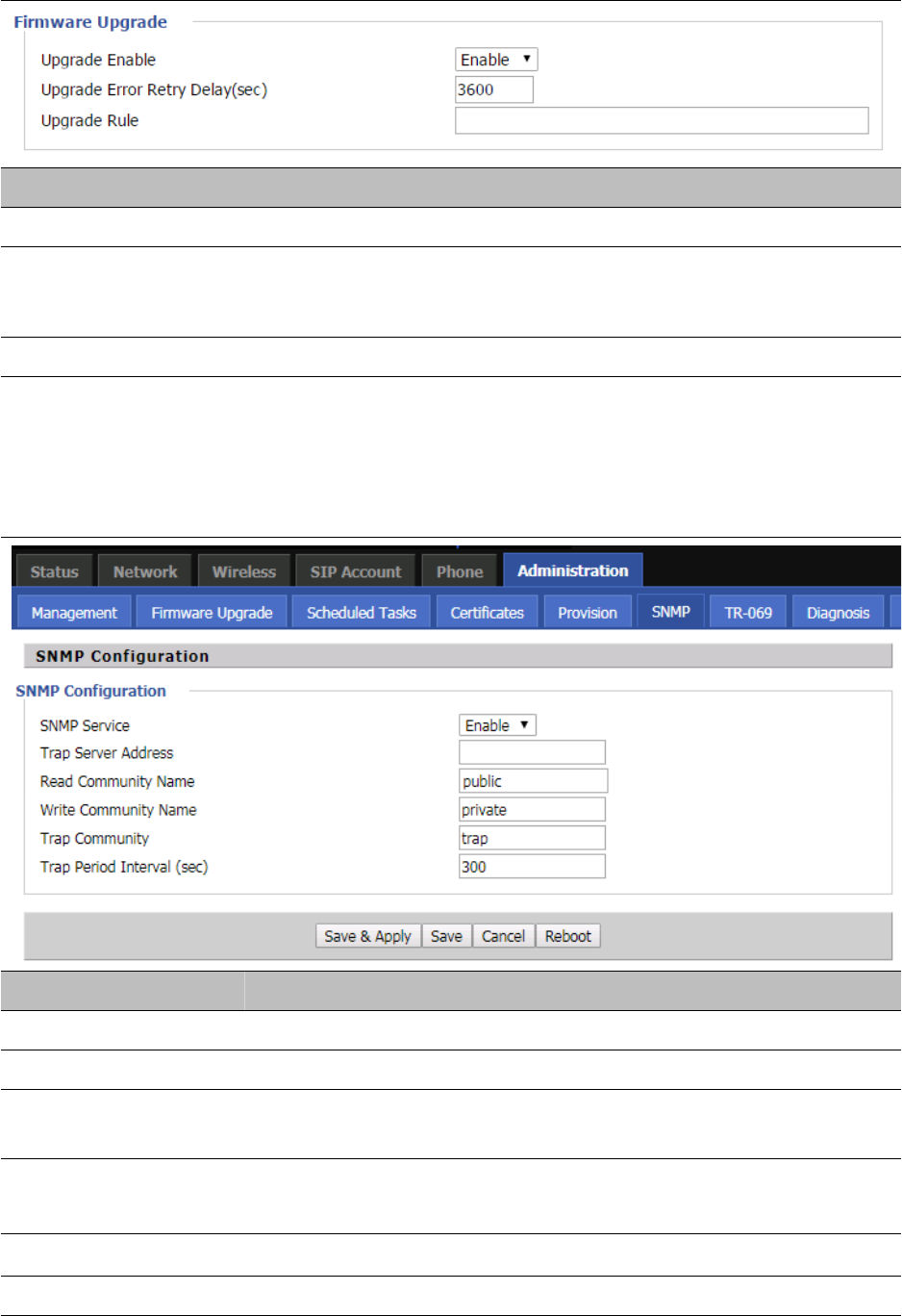
Chapter 3 Web Interface
91
Table 71 Firmware Upgrade
Field Name Description
Upgrade Enable Enable firmware upgrade via provision or not
Upgrade Error Retry
Delay(sec)
If the last upgrade fails, the router will try upgrading
again after “Upgrade Error Retry Delay” period, default is 3600s
Upgrade Rule URL of upgrade file
SNMP
Table 72 SNMP
Field Name Description
SNMP Service Enable or Disable the SNMP service
Trap Server Address Enter the trap server address for sending SNMP traps
Read Community Name String value that is used as a password to request information via SNMP
from the device
Write Community Name String value that is used as a password to write configuration values to the
device SNMP
Trap Community String value used as a password for retrieving traps from the device
Trap period interval(sec) The interval for which traps are sent from the device
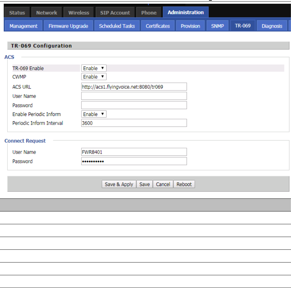
Chapter 3 Web Interface
92
TR-069
TR-069 provides the possibility of auto configuration of internet access devices and reduces the cost of
management. TR-069 (short for Technical Report 069) is a DSL Forum technical specification entitled CPE WAN
Management Protocol (CWMP). It defines an application layer protocol for remote management of end-user
devices. Using TR-069, the terminals establish connection with the Auto Configuration Servers (ACS) and get
configured automatically.
Device Configuration using TR-069
The TR-069 configuration page is available under Administration menu.
Table 73 TR069
Field Name Description
ACS parameters
TR069 Enable Enable or Disable TR069
CWMP Enable or Disable CWMP
ACS URL ACS URL address
User Name ACS username
Password ACS password
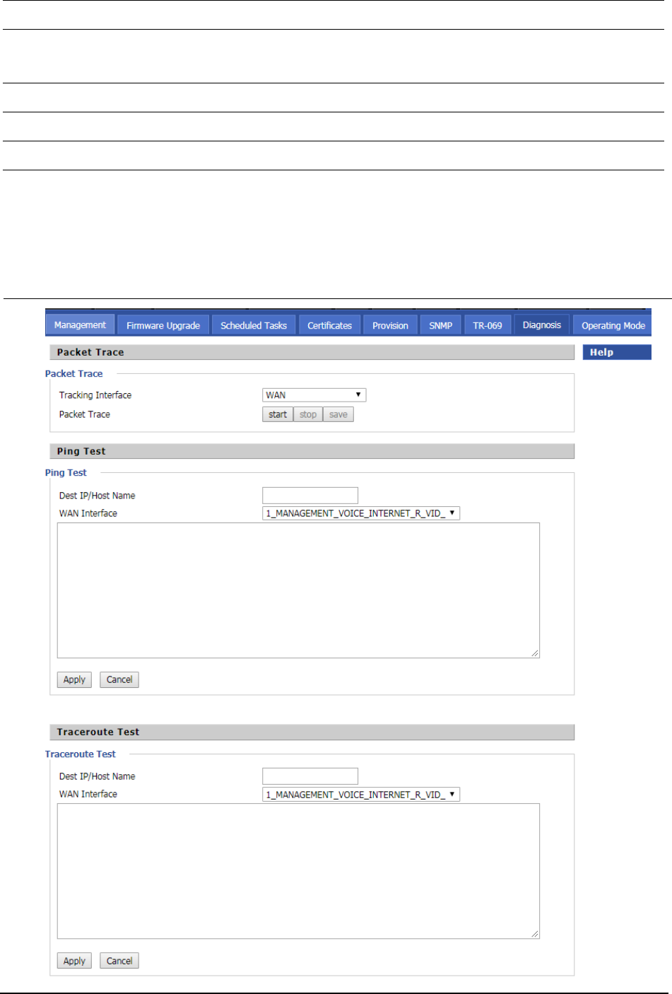
Chapter 3 Web Interface
93
Diagnosis
In this page, user can do packet trace, ping test and traceroute test to diagnose the device’s connection status.
Table 74
D
iagnosis
Periodic Inform Enable Enable the function of periodic inform or not. By default it is Enabled
Periodic Inform Interval Periodic notification interval with the unit in seconds. The default value is
3600s
Connect Request parameters
User Name The username used to connect the TR069 server to the DUT.
Password The password used to connect the TR069 server to the DUT.
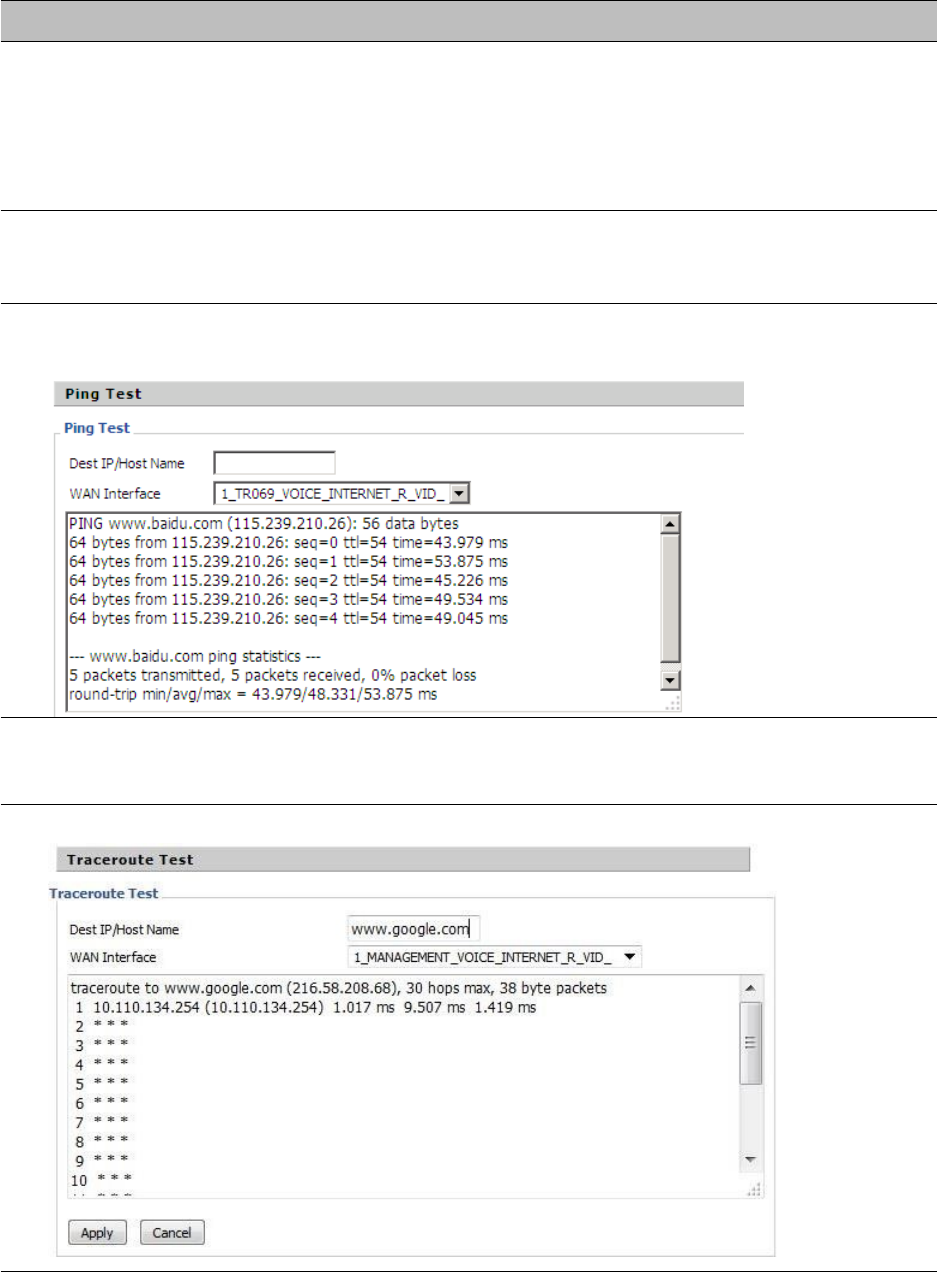
Chapter 3 Web Interface
94
Description
1. Packet Trace
Users can use the packet trace feature to intercept packets which traverse the device. Click the Start
button to start home gateway tracking and keep refreshing the page until the message trace shows to
stop, click the Save button to save captured packets.
2. Ping Test
Enter the destination IP or host name, and then click Apply, device will perform ping test.
3. Traceroute Test
Enter the destination IP or host name, and then click Apply, device will perform traceroute test.
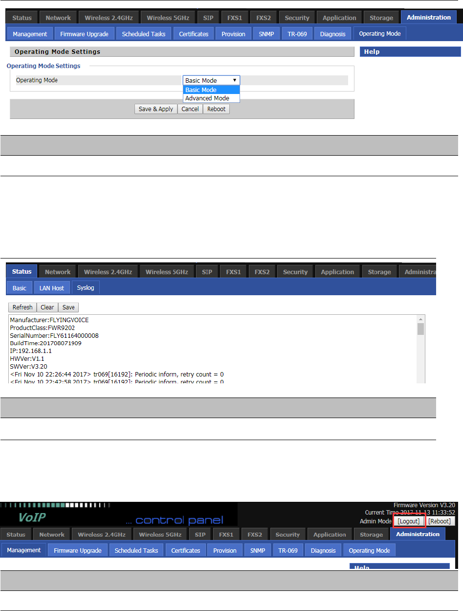
Chapter 3 Web Interface
95
Operating Mode
Table 75 Operating mode
Description
C
hoose the Operation Mode as Basic Mode or Advanced Mode
System Log
Table 76 System log
Description
I
f you enable the system log in Status/syslog webpage, you can view the system log in this webpage.
Logout
Table 77 Logout
Description
P
ress the logout button to logout, and then the login window will appear.

Chapter 3 Web Interface
96
Reboot
Press the button to reboot the device.

97
Chapter 4 IPv6 address configuration
The router devices support IPv6 addressing.This chapter covers:
•
Introduction
•
IPv6 Advance
•
Configuring IPv6
•
Viewing WAN port status
•
IPv6 DHCP configuration for LAN/WLAN clients
•
LAN DHCPv6
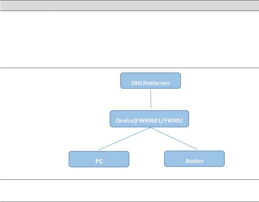
Chapter 4 IPv6 address configuration
98
Introduction
DHCPv6 protocol is used to automatically provision/configure IPv6 capable end points in a local
network. In addition to acquiring an IPv6 IP address for the WAN interface and its associated
LAN/WLAN clients, the devices are also capable of prefix delegation.
The Routers devices support the following types of modes of IPv6 addresses:
•
Stateless DHCPv6
•
Statefull DHCPv6
Table 78 IPv6 Modes
Mode
Description
Stateless In Stateless DHCPv6 mode, the Routers devices listen for ICMPv6 Router
Advertisements messages which are periodically sent out by the routers on the
local link or requested by the node using a Router Advertisements solicitation
message. The device derives a unique IPv6 address using prefix receives from the
router and its own MAC address.
Statefull In Statefull DHCPv6 mode, the client works exactly as IPv4 DHCP, in which hosts
receive both their IPv6 addresses and additional parameters from the DHCP server.
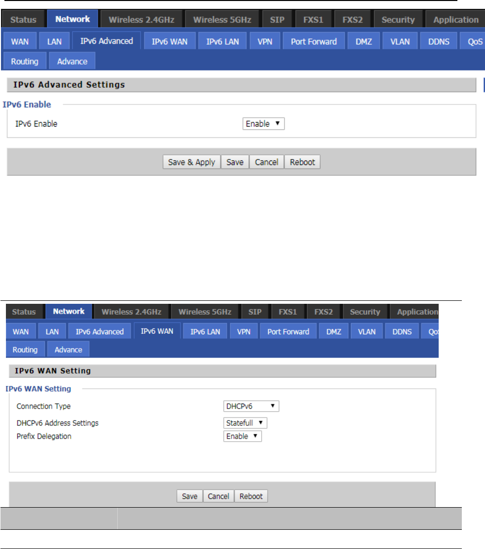
Chapter 4 IPv6 address configuration
99
IPv6 Advance
To enable IPv6 functionality:
Navigate to Network > IPv6 Advanced page.
Select Enable from the IPv6 Enable drop-down list.
Click Save.
Table 79 Enabling IPv6
Configuring IPv6
Configuring Statefull IPv6
1. Navigate to Network > IPv6WAN page. The following window is displayed:
Table 80 Configuring Statefull IPv6
Field Name Description
Connection Type Select connection type
Chapter 4 IPv6 address configuration
100
DHCPv6 Address Settings Set it to statefull mode.
Prefix Delegation Select Enable.
Configuring Stateless IPv6
Table 81 Configuring Stateless IPv6
Field Name Description
Connection Type Select connection type
DHCPv6 Address Settings Set it to stateless mode.
Prefix Delegation Select Enable.
Chapter 4 IPv6 address configuration
101
Viewing WAN port status
To view the status of WAN port:
Navigate to Status page.
IPv6 DHCP configuration for LAN/WLAN clients
Wired and wireless clients connected to the Routers can obtain their IPv6 addresses based on how the LAN s
ide DHCPv6 parameters are configured. The Routers can be either configured as a DHCPv6 server in which the
LAN/WLAN clients get IPv6 addresses from the configured pool.If DHCP server is disabled on the Routers, the
clients will get IPv6 addresses from the external DHCPv6 server configured in the network.
Chapter 4 IPv6 address configuration
102
LAN DHCPv6
When IPv6 is enabled, the LAN/WLAN clients of Routers can be configured to receive IPv6 addresses from locally
configured IPv6 pool or from an external DHCPv6 server.
To enable LAN DHCPv6 service:

103
Chapter 5 Troubleshooting Guide
This chapter covers:
•
Configuring PC to get IP Address automatically
•
Cannot connect to the Web GUI
•
Forgotten Password
Chapter 5 Troubleshooting Guide
104
Configuring PC to get IP Address automatically
Follow the below process to set your PC to get an IP address automatically:
Step 1 : Click the “Start” button
Step 2 : Select “control panel”, then double click “network connections” in the “control panel”
Step 3 : Right click the “network connection” that your PC uses, select “attribute” and you can see
theinterfaceasshowninFigure3.
Step 4.: Select “Internet Protocol (TCP/IP)”, click “attribute” button, then click the “Get IP address automatically”.
Chapter 5 Troubleshooting Guide
105
Cannot connect to the Web
Solution:
•
Check if the Ethernet cable is properly connected
•
Check if the URL is correct. The format of URL is: http:// the IP address
•
Check on any other browser apart from Internet explorer such Google
•
Contact your administrator, supplier or ITSP for more information or assistance.
Forgotten Password
If you have forgotten the management password, you cannot access the configuration web GUI. Solution:
To factory default: press and hold reset button for 10 seconds.