Foerster Technik MULTIREADER MultiReader User Manual OBJ BUCH 300 003
Foerster Technik GmbH MultiReader OBJ BUCH 300 003
user manual
September 26, 2011
(DE-September 26, 2011)
Mounting Instructions
Multi-Identification
S22.1e

2

Table of content 3
Table of content
1 Introduction . . . . . . . . . . . . . . . . . . . . . . . . . . . . . . . . . . . . . . . . . . . . . . . . . . . . . . . . . . .5
1.1 Copyright . . . . . . . . . . . . . . . . . . . . . . . . . . . . . . . . . . . . . . . . . . . . . . . . . . . . . . . . . . . . . . . . . . . . . . . 5
1.2 Disposal . . . . . . . . . . . . . . . . . . . . . . . . . . . . . . . . . . . . . . . . . . . . . . . . . . . . . . . . . . . . . . . . . . . . . . . . 5
1.3 Transport . . . . . . . . . . . . . . . . . . . . . . . . . . . . . . . . . . . . . . . . . . . . . . . . . . . . . . . . . . . . . . . . . . . . . . . 5
1.4 Contact details of the manufacturer . . . . . . . . . . . . . . . . . . . . . . . . . . . . . . . . . . . . . . . . . . . . . . . . . . . 5
2 For your safety. . . . . . . . . . . . . . . . . . . . . . . . . . . . . . . . . . . . . . . . . . . . . . . . . . . . . . . . .7
2.1 Target group . . . . . . . . . . . . . . . . . . . . . . . . . . . . . . . . . . . . . . . . . . . . . . . . . . . . . . . . . . . . . . . . . . . . . 7
2.1.1 Necessary qualifications of the owner. . . . . . . . . . . . . . . . . . . . . . . . . . . . . . . . . . . . . . . . . . 7
2.1.2 Necessary qualifications of the service technician . . . . . . . . . . . . . . . . . . . . . . . . . . . . . . . . 7
2.2 Intended use of the multi-identification unit . . . . . . . . . . . . . . . . . . . . . . . . . . . . . . . . . . . . . . . . . . . . . 7
2.3 Indication of hazards. . . . . . . . . . . . . . . . . . . . . . . . . . . . . . . . . . . . . . . . . . . . . . . . . . . . . . . . . . . . . . . 7
2.4 Safety signs on the machine. . . . . . . . . . . . . . . . . . . . . . . . . . . . . . . . . . . . . . . . . . . . . . . . . . . . . . . . . 8
2.5 Obligations of the owner. . . . . . . . . . . . . . . . . . . . . . . . . . . . . . . . . . . . . . . . . . . . . . . . . . . . . . . . . . . . 9
2.6 Obligations of the operator . . . . . . . . . . . . . . . . . . . . . . . . . . . . . . . . . . . . . . . . . . . . . . . . . . . . . . . . . . 9
2.7 Structural alterations. . . . . . . . . . . . . . . . . . . . . . . . . . . . . . . . . . . . . . . . . . . . . . . . . . . . . . . . . . . . . . 10
3 Technical data . . . . . . . . . . . . . . . . . . . . . . . . . . . . . . . . . . . . . . . . . . . . . . . . . . . . . . . .11
3.1 Multi-identification. . . . . . . . . . . . . . . . . . . . . . . . . . . . . . . . . . . . . . . . . . . . . . . . . . . . . . . . . . . . . . . . 11
3.2 Accessories . . . . . . . . . . . . . . . . . . . . . . . . . . . . . . . . . . . . . . . . . . . . . . . . . . . . . . . . . . . . . . . . . . . . 12
3.2.1 Mounting bracket (with front plate mounting) . . . . . . . . . . . . . . . . . . . . . . . . . . . . . . . . . . . 12
3.3 FCC . . . . . . . . . . . . . . . . . . . . . . . . . . . . . . . . . . . . . . . . . . . . . . . . . . . . . . . . . . . . . . . . . . . . . . . . . . 13
3.4 IC . . . . . . . . . . . . . . . . . . . . . . . . . . . . . . . . . . . . . . . . . . . . . . . . . . . . . . . . . . . . . . . . . . . . . . . . . . . . 13
4 Putting the unit into service . . . . . . . . . . . . . . . . . . . . . . . . . . . . . . . . . . . . . . . . . . . . .15
4.1 Notes on installation . . . . . . . . . . . . . . . . . . . . . . . . . . . . . . . . . . . . . . . . . . . . . . . . . . . . . . . . . . . . . . 15
4.2 Squelch values and identification ranges . . . . . . . . . . . . . . . . . . . . . . . . . . . . . . . . . . . . . . . . . . . . . . 15
4.3 Installing the multi-identification unit. . . . . . . . . . . . . . . . . . . . . . . . . . . . . . . . . . . . . . . . . . . . . . . . . . 16
4.3.1 On front plate. . . . . . . . . . . . . . . . . . . . . . . . . . . . . . . . . . . . . . . . . . . . . . . . . . . . . . . . . . . . 17
4.3.2 On the left or right in the Flex100 partition . . . . . . . . . . . . . . . . . . . . . . . . . . . . . . . . . . . . . 19
4.4 Connecting the multi-identification unit to the main board . . . . . . . . . . . . . . . . . . . . . . . . . . . . . . . . . 20
5 Diagnosis . . . . . . . . . . . . . . . . . . . . . . . . . . . . . . . . . . . . . . . . . . . . . . . . . . . . . . . . . . . .21
5.1 Checking the feeding boxes . . . . . . . . . . . . . . . . . . . . . . . . . . . . . . . . . . . . . . . . . . . . . . . . . . . . . . . . 21
6 Warnings. . . . . . . . . . . . . . . . . . . . . . . . . . . . . . . . . . . . . . . . . . . . . . . . . . . . . . . . . . . . .23
6.1 Identification . . . . . . . . . . . . . . . . . . . . . . . . . . . . . . . . . . . . . . . . . . . . . . . . . . . . . . . . . . . . . . . . . . . . 23
7 Maintenance . . . . . . . . . . . . . . . . . . . . . . . . . . . . . . . . . . . . . . . . . . . . . . . . . . . . . . . . . .25
7.1 Maintenance intervals and activities. . . . . . . . . . . . . . . . . . . . . . . . . . . . . . . . . . . . . . . . . . . . . . . . . . 25
7.1.1 Daily . . . . . . . . . . . . . . . . . . . . . . . . . . . . . . . . . . . . . . . . . . . . . . . . . . . . . . . . . . . . . . . . . . 25
7.2 Care . . . . . . . . . . . . . . . . . . . . . . . . . . . . . . . . . . . . . . . . . . . . . . . . . . . . . . . . . . . . . . . . . . . . . . . . . . 25

4

Introduction 5
1 Introduction
These mounting instructions put you in the position to operate
the multi-identification unit safely as intended.
> Please read the mounting instructions carefully before putting
the multi-identification unit into service.
> Keep the mounting instructions ready and available at all
times and pass it on to the next user.
> Observe all warnings and safety instructions in these mount-
ing instructions at all times.
1.1 Copyright
The copyright for these mounting instructions is reserved by
Förster-Technik.
1.2 Disposal
All components, liquids and solids must be disposed of in com-
pliance with the official local regulations for waste prevention and
appropriate waste recycling or disposal which apply in your
country. Also observe the corresponding safety data sheets.
1.3 Transport
The multi-identification unit is delivered in a box with the dimen-
sions 45 x 30 x 10 cm.
> Check the product for visible signs of damage upon delivery
and report them immediately to the carrier.
1.4 Contact details of the manufacturer
Please get in touch with us if you have any questions on our
products or require technical support!
Please note down the item number and the serial number stated
on the device to have it ready and available whenever you make
a call.

6 Introduction
Item no.:
Serial no.:
Our contact details:
Förster-Technik GmbH
Gerwigstr. 25
D-78234 Engen, Germany
Phone: +49 / (0)7733 / 9406 - 0
Fax: +49 / (0)7733 / 9406 - 99
info@foerster-technik.de
www.foerster-technik.de

For your safety 7
2 For your safety
2.1 Target group
2.1.1 Necessary qualifications of the owner
The owner must be a trained farmer or have good practical expe-
rience in farming. He must be familiar with the relevant accident
prevention regulations and generally accepted safety regula-
tions.
2.1.2 Necessary qualifications of the service technician
Only trained service technicians are authorised to install the
multi-identification unit, put it into service and subject it to main-
tenance and repairs.
Service technicians are electricians with appropriate qualifica-
tions, i.e. they are able to assess the work assigned to them and
detect potential risks on the basis of their technical training as
well as their knowledge of the relevant standards. This also
includes knowledge of relevant accident prevention regulations,
generally accepted safety regulations, EU guidelines and coun-
try-specific standards and provisions.
2.2 Intended use of the multi-identification unit
Only use the multi-identification unit as an electronic transmitter
and receiver unit for RFID for Vario (+) and Compact (+) auto-
matic calf feeders.
2.3 Indication of hazards
Hazards are indicated by a key word and a corresponding sign,
depending on the severity and probability:
Danger!
For an imminent danger, resulting in serious injuries or
death.
8 For your safety
However, it is just as important to observe any other notes and
information which are not highlighted to avoid failures which, in
turn, may cause direct or indirect injuries or material damage.
2.4 Safety signs on the machine
The safety signs on the machine are an important part of the
safety concept and help prevent accidents.
They indicate danger areas at the machine and warn against
residual risks.
Keep all safety signs completely in legible condition and renew
them if they become unreadable.
Warning!
For a potentially dangerous situation which may cause se-
rious injuries or even death.
Caution!
For a potentially dangerous situation which may cause mi-
nor injuries or material damage.
Attention For a potentially harmful situation in which the product or an
item can become damaged within its environment.
Note For application notes and other useful information.
Do not spray-wash!
Water (liquids) can damage electrical components.
•Do not spray the multi-identification unit. Do not use any
high-pressure cleaners or similar equipment either.
•To clean the multi-identification unit, wipe it only with a
damp cloth.

For your safety 9
2.5 Obligations of the owner
The owner is obliged to:
•Rule out misuse by children,
•Carefully read and understand these mounting instructions
before putting the multi-identification unit into service,
•Only allow operating personnel to work with/on the multi-iden-
tification unit who:
•Are familiar with the basic operational safety and acci-
dent prevention regulations,
•Have been given instructions on work with/on the multi-
identification unit,
•Have read and understood these mounting instructions,
•Operate the multi-identification unit only as intended,
•Do not change the design or functions of the multi-identifica-
tion unit,
•Operate the multi-identification unit only in perfect functional
condition,
•Subject the multi-identification unit to regular visual inspection
for possible damage and have it rectified by a service techni-
cian if necessary,
•Make sure the multi-identification unit's connection point is
easy to access at all times,
•Make sure the multi-identification unit is mounted at the point
intended,
•Protect the multi-identification unit and the corresponding ca-
ble from exposure to sunlight.
2.6 Obligations of the operator
Before beginning work, the operator is obliged to:

10 For your safety
•Observe the basic operational safety and accident prevention
regulations,
•Read and understand these mounting instructions,
•Observe all the safety information and instructions included in
these mounting instructions.
The compulsory accident prevention regulations which apply at
the operation site in the country of use and the technical rules for
safety-related and specialist work must also be observed by all
means.
2.7 Structural alterations
The multi-identification unit must not be subjected to any unau-
thorised alterations at any time.
Only original spare parts, wear parts and accessories may be
used, since any warranty claims will otherwise expire.
Technical data 11
3 Technical data
3.1 Multi-identification
Height: 430 mm
Width: 300 mm
Depth: 100 mm
12 Technical data
3.2 Accessories
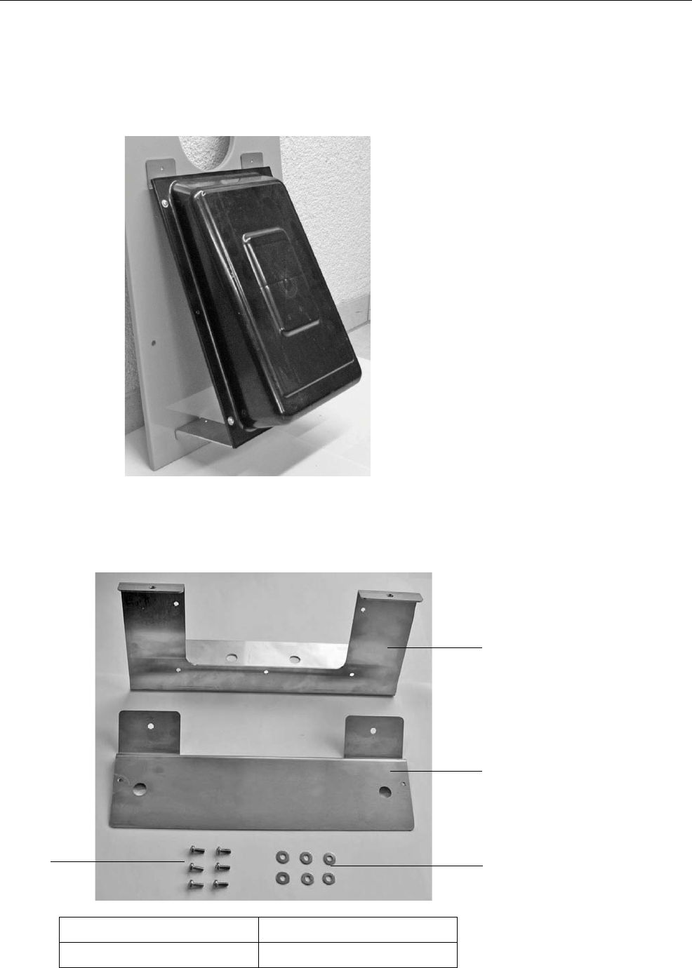
3.2.1 Mounting bracket (with front plate mounting)
3.2.1.1 Scope of delivery of the mounting bracket
2
1
3
4
1 Upper mounting bracket 3 Washers (6x)
2 Lower mounting bracket 4 Fillister head screws (6x)

Technical data 13
3.3 FCC
This equipment complies with Part 15 of the FCC rules. Any
changes or modifications not expressly approved by the Manu-
facturer could void the user's authority to operate the equipment.
This device complies with Part 15 of the FCC rules subject to the
following two conditions:
1. This device may not cause harmful interference.
2. This device must accept all interference received, including
interference that may cause undesired operation.
3.4 IC
This device complies with Industry Canada license-exempt RSS
standard(s). Operation is subject to the following two conditions:
(1) this device may not cause interference, and (2) this device
must accept any interference, including interference that may
cause undesired operation of the device.
This device complies with Health Canada's Safety Code 6 / IC
RSS-210. The installer of this device should ensure that RF radi-
ation is not emitted in excess of the Health Canada's require-
ment.
Note This equipment has been tested and found to comply with
the limits for a Class A digital device, pursuant to part 15 of
the FCC Rules. These limits are designed to provide rea-
sonable protection against harmful interference when the
equipment is operated in a commercial environment. This
equipment generates, uses, and can radiate radio frequen-
cy energy and, if not installed and used in accordance with
the instruction manual, may cause harmful interference to
radio communications. Operation of this equipment in a
residential area is likely to cause harmful interference in
which case the user will be required to correct the interfer-
ence at his own expense.

14 Technical data
Cet appareil est conforme avec Industrie Canada RSS standard
exempts de licence (s). Son utilisation est soumise à Les deux
conditions suivantes: (1) cet appareil ne peut pas provoquer
d'interférences et (2) cet appareil doit accepter Toute inter-
férence, y compris les interferences qui peuvent causer un mau-
vais fonctionnement du dispositif.
Cet appareil est conforme avec Santé Canada Code de sécurité
6 / IC RSS-210. Le programme d'installation de cet appareil doit
s'assurer que les rayonnements RF n'est pas émis au-delà de
l'exigence de Santé Canada.

Putting the unit into service 15
4 Putting the unit into service
4.1 Notes on installation
> Keep the distance between the antenna and the transmitter
as small as possible.
> Only the animal to be identified in the box is permitted to be
within the range of the antenna.
> Check the range of the antennas using the antenna test (see
5 Diagnosis, page 21).
> If an animal entitled to feed is outside the feeding box, but
within in the range of the antenna, a portion might be pre-
pared that the animal will not receive. If necessary, block the
area next to the feeding box.
If two animals are identified simultaneously by one antenna, ani-
mal identification is interrupted for both animals.
> The distance between two antennas should be approx.
100 cm to avoid any range overlapping. In the event of double
or external identification, the antennas will need to be shield-
ed using earthed metal plates.
4.2 Squelch values and identification ranges
The approx. range of the antennas is 15 - 25 cm.
The antenna version is decisive for the identification range. With
Nedap micro-identification, you can set the range via the squelch
value.
The squelch values and the identification ranges for the various
identification systems are listed in the following table. These
squelch values are based on experience and are set at the fac-
tory.
16 Putting the unit into service
4.3 Installing the multi-identification unit
The multi-identification unit can be fastened at three different
positions to the Flex100 partition:
•Front plate
•Left side
•Right side
System Squelch (default values) Identification range
Collar
(X responder system) -20 - 25 cm
Earmark in the collar
Earmark
(Nedap system)
015 - 18 cm
Earmark in the collar ear-
mark
(Tiris system)
-15 - 18 cm
Note If mounted at the side, the height of the identification unit
can be adapted to the position of the transponder.
Note If X-Responders are used, it is recommended to mount the
multi-identification unit with the bracket (optional) on the
front plate.
Putting the unit into service 17
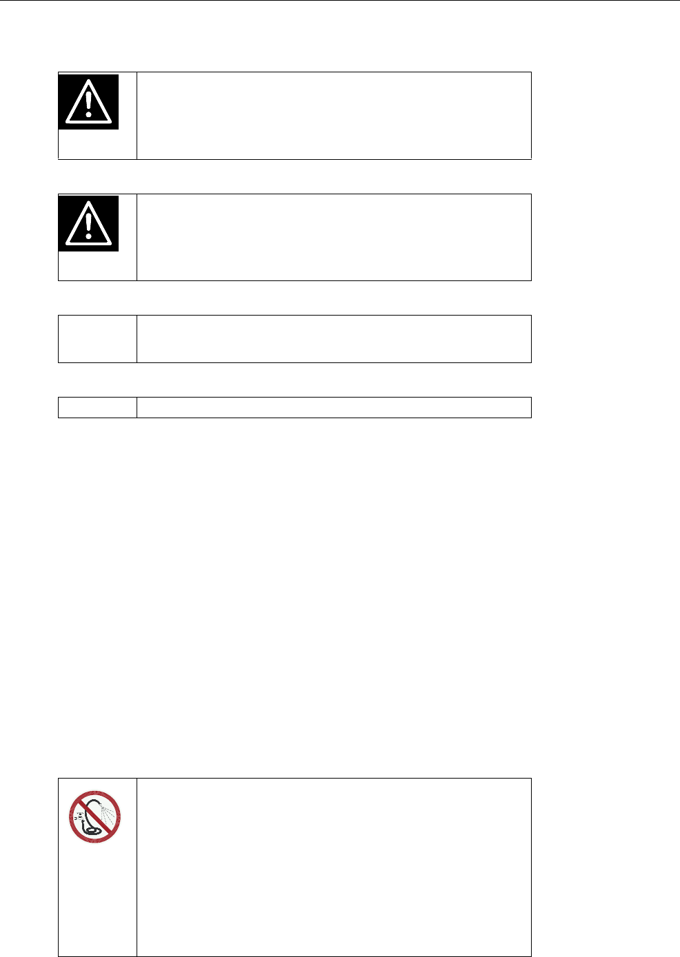
4.3.1 On front plate
4.3.1.1 Without bracket
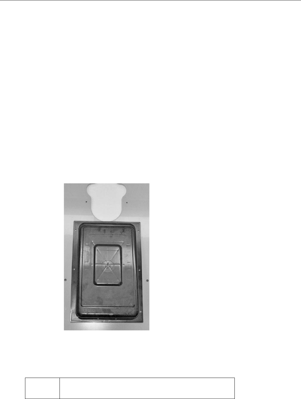
Proceed as follows for the installation:
1. Place the antenna box on the front plate, in the centre. Please
make sure that:
•The flat side faces upwards,
•The upper edge of the antenna box is flush with the low-
er edge of the recess on the front plate.
2. Fasten the antenna box to the front plate using the screws en-
closed (see figure).
3. Drill a hole into the front plate directly beneath the antenna
box and feed the antenna cable through it.
Attention Make sure the antenna cable is installed outside the animal
area to prevent it from being damaged.
18 Putting the unit into service
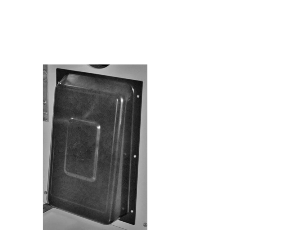
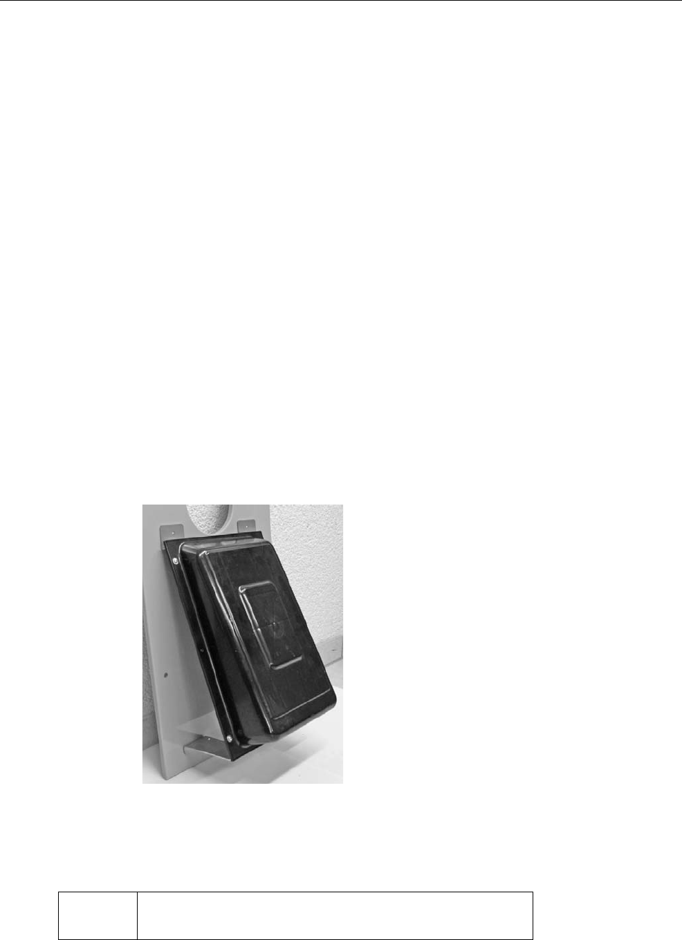
4.3.1.2 With bracket (optional)
1. Fasten the bracket from the rear to the antenna box using the
screws and washers enclosed to the scope of delivery of the
bracket.
2. Screw the antenna box to the antenna cover using the re-
maining screws and washers.
3. Place the antenna box on the front plate, in the centre. Please
make sure that:
•The flat side faces upwards,
•The upper edge of the antenna box is flush with the low-
er edge of the recess on the front plate.
4. Fasten the antenna box to the front plate using the screws en-
closed (the drill holes are already pre-drilled on the bracket).
5. Drill a hole into the front plate directly beneath the antenna
box and feed the antenna cable through it.
Attention Make sure the antenna cable is installed outside the animal
area to prevent it from being damaged.
Putting the unit into service 19
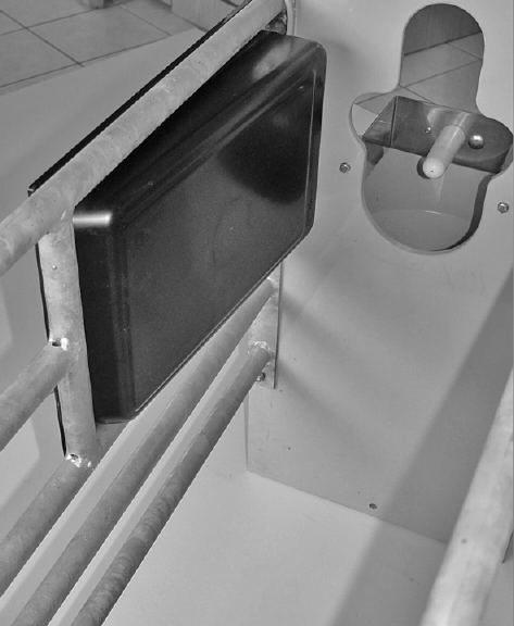
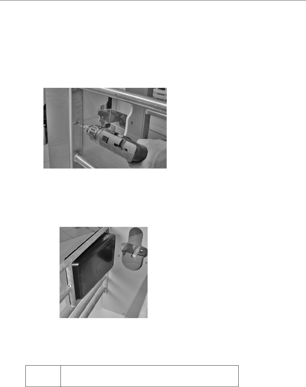
4.3.2 On the left or right in the Flex100 partition
Proceed as follows for the installation:
1. Before attaching the antenna, drill the opening for the cable at
the position displayed below.
2. Fasten the antenna box to the side part of the feeding box us-
ing the screws enclosed so that the flat side faces the rear
(see figure).
3. Feed the antenna cable through the cable opening that you
drilled before.
Attention Make sure the antenna cable is installed outside the animal
area to prevent it from being damaged.
20 Putting the unit into service
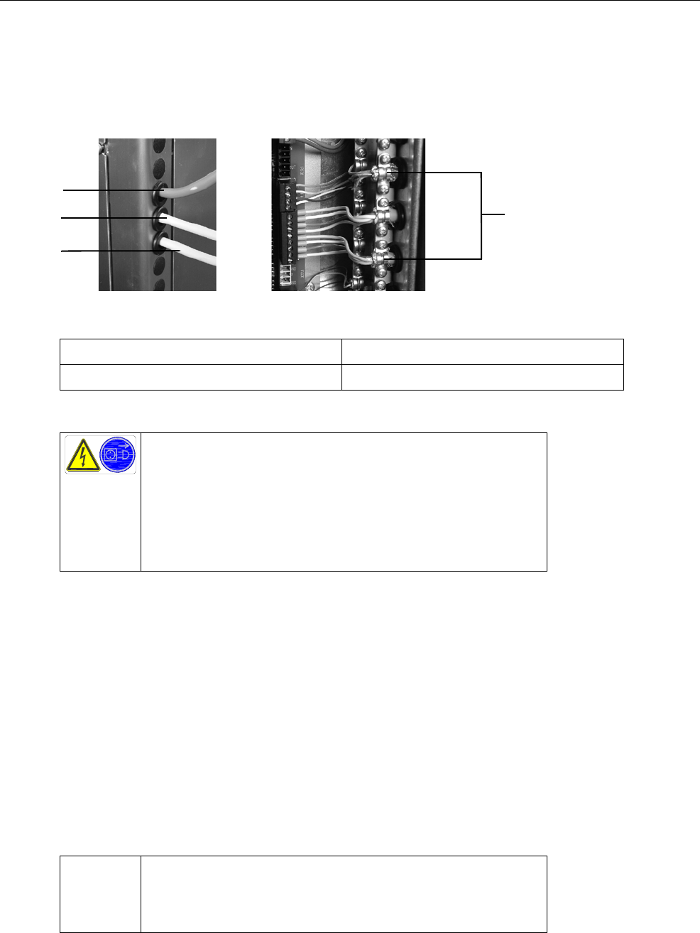
4.4 Connecting the multi-identification unit to the main board
1. Remove the housing cover from the control box.
2. There are two more cable sleeves under the cable sleeve for
the hand terminal cable. Push the antenna cables through
them into the control box.
3. Connect the cables of the multi-identification unit / antenna to
the main board in accordance with the wiring diagram.
4. Fasten the wiring looms to the cable brides.
5. Connect the control box.
4
1
3
2
1 Cable of the hand-held terminal 3 Antenna cable of feeding station 2
2 Antenna cable of feeding station 1 4 Cable clamps
Danger due to live electrical components!
Live electrical components.
Danger of death by electric shock!
•Always disconnect the mains plug before starting any
work on the control box of the automatic feeder.
Attention To ensure earthing, you must also connect a shield of
approx. 1 cm (if available). Make sure that the shield lies on
the sheath and not on the cable insulation.

Diagnosis 21
5 Diagnosis
The Diagnosis menu of the automatic feeder is for checking the
multi-identification unit and its functions. It facilitates trouble-
shooting if there is a technical problem with the multi-identifica-
tion unit. The menus relevant for the multi-identification unit are
available via the following menu path:
> Diagnosis >Boxes
5.1 Checking the feeding boxes
You can check whether the identification of the feeding box
works here.
1. > Diagnosis > Stations > Feed > Feeding station 1...
2. To check the identification (antenna test), hold the transmitter
near the antenna. The transmitter number is displayed in the
No. line.
If the transmitter number is not recognised, proceed as follows:
1. Check in the setup whether the correct identification system
is configured.
2. Check the data line between antenna and automatic feeder
for damage.
3. Check the setup for the allocation of the box that causes iden-
tification problems.
Diagnosis
Valves
Motors
Heating
Sensors
Stations
Control
Version
Station
Feed
Concentrate
<Feeding station 1>
No.ǂ: 11456
Pump: start?
Teat slider: open?
C.Protect: close?
Feed sensor: active
Motor pulses: 22
Control: IFS-F 1
Animal scales
search?

22 Diagnosis

Warnings 23
6 Warnings
Warnings indicate problems that do not interrupt the auto-
matic operation of the automatic feeder. Warnings are indi-
cated by the LED flashing on the hand terminal of the automatic
feeder.
Some warnings disappear when the fault has been rectified.
Some need to be (additionally) deleted by pressing .
6.1 Identification
If the identification system is not working, this message appears
on the display:
> Check the cables leading to the antenna for any visible dam-
age (example: animal bites).
> Also check that the (correct) antenna is activated.
The warning is automatically deleted when the fault has been
rectified.
Warning
Identification
<Identification>
No connection

24 Warnings
Maintenance 25
7 Maintenance
The visual inspection of the components can be conducted by
the owner/operator.
Repair work must always be performed by a service technician.
7.1 Maintenance intervals and activities
7.1.1 Daily
Visual inspection of the components
All components must be checked visually every day for damage
and deposits. If any damage is detected during the visual inspec-
tion, the faulty components have to be replaced by a service
technician before work can be resumed with the multi-identifica-
tion unit.
7.2 Care
You should have dirt removed from the multi-identification unit
from time to time. However, soiling does not have any negative
effects on the identification results.
Note If you detect any faults or damage to the multi-identification
unit between the maintenance intervals recommended be-
low, you must make sure they are rectified immediately by
a service technician as required.
Do not spray-wash!
Water (liquids) can damage electrical components.
•Do not spray-wash the multi-identification unit. Do not
use any high-pressure cleaners or similar equipment ei-
ther.
•To clean the multi-identification unit, only wipe it with a
damp cloth.

26 Maintenance