Fomotech A4000SERIES Industrial Crane Remote Controler User Manual A4K 01 06 255 266 1
Fomotech International Corp. Industrial Crane Remote Controler A4K 01 06 255 266 1
UserManual.wiki
>
Fomotech
>
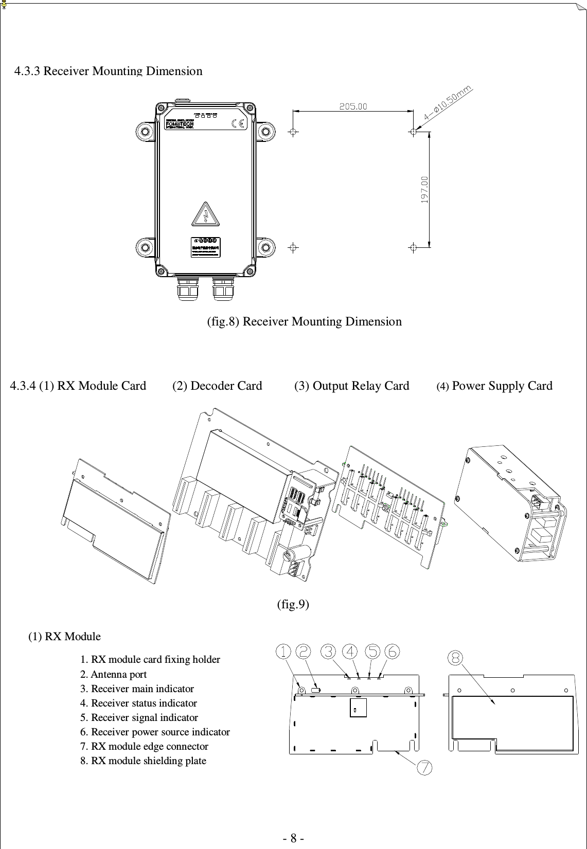
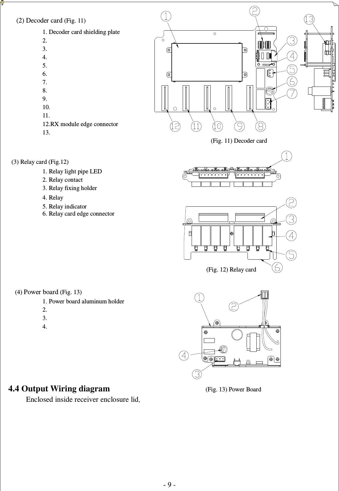
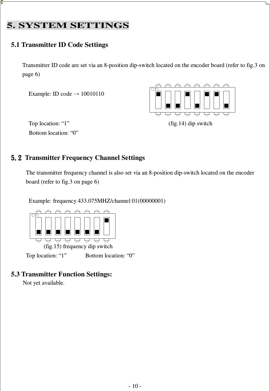
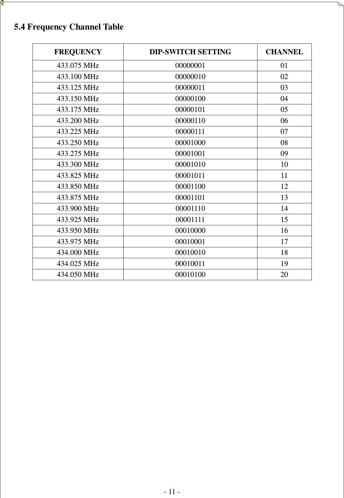
A4000SERIES User Manual
Manual
Navigation menu
Upload a User Manual
Namespaces
Wiki Guide
HTML
PDF
Info
Views
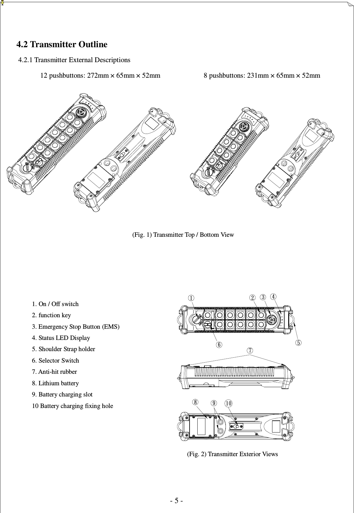
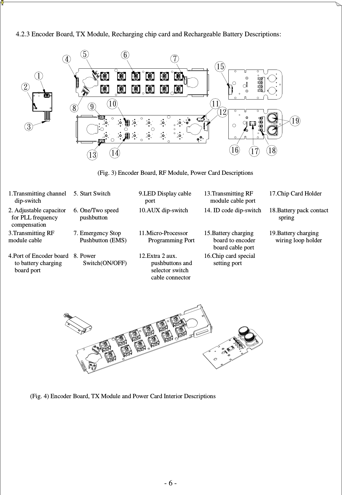
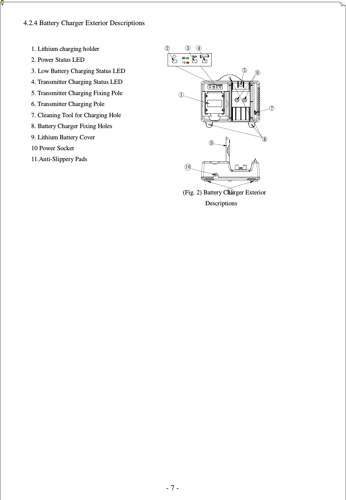
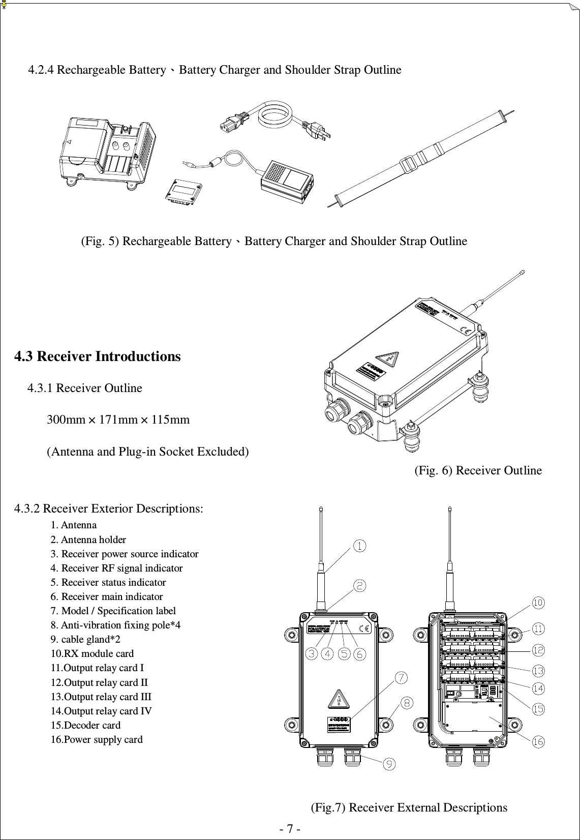
User Manual
Discussion / Help
Navigation