Fomotech A4000SERIES Industrial Crane Remote Controler User Manual A4K 01 06 255 266 1
Fomotech International Corp. Industrial Crane Remote Controler A4K 01 06 255 266 1
Fomotech >
Manual

- 1 -
T
TA
AB
BL
LE
E
O
OF
F
C
CO
ON
NT
TE
EN
NT
TS
S
1
3
SAFETY INSTRUCTION
2
4
INTRODUCTION
3~8
4.1 SYSTEM TYPES
3
4.1.1 8-PUSHBUTTON TYPES
3~4
4.1.2 12-PUSHBUTTON TYPES
4~5
4.1.3 CUSTOM-MADE TYPES
5
4.2 TRANSMITTER INSTRUCTION
5
4.2.1 TRANSMITTER OUTLINE
5
4.2.2 RECEIVER EXTERIOR DESCRIPTION
6
4.2.3
(1)
ENCODER BOARD
(2) TX MODULE
(3) RECHARGE SHIP
CARD
6
4.2.4
(1) RECHARGEABLE BATTERY
(2) BATTERY CHARGER
(3) SHOULDER
STRAP
7
4.3 RECEIVER INSTRUCTION
7
4.3.1 RECEIVER OUTLINE
7
4.3.2 RECEIVER EXTERIOR OUTLINE
7
4.3.3 RECEIVER MOUNTING DIMENSION
8
4.3.4
(1)
RX MODULE CARD
(2)
DECODER CARD
(3) RELAY
CARD
(4)
POWER SUPPLY CARD
8~9
4.4 BATTERY CHARGER INTRODUCTION
4.5 OUTPUT WIRING DIAGRAM
9
5
SYSTEM SETTINGS
10~11
5.1 TRANSMITTER ID CODE SETTINGS
10
5.2 TRANSMITTER FREQUENCY CHANNEL
SETTINGS
10
5.3 TRANSMITTER FUNCTION SETTINGS
10
5.4 FREQUENCY CHANNEL TABLE
10
5.5 RECEIVER FUNCTION SETTINGS
11
6
RECEIVER INSTALLATION
12~13
6.1 RECEIVER LED DISPLAY
12
6.2 PREPARATION
12
6.3 STEP-BY-STEP INSTALLATION
13
7
TRANSMITTER INSTALLATION
14
7.1 STEP-BY-STEP INSTALLATION
14
7.2 TRANSMITTER LED DISPLAY
14
8
BATTERY CHARGING
15
9
TROUBLE SHOOTING
15
10
SYSTEM SPECIFICATION
16
10.1 TRANSMITTER SPECIFICATION
16
10.2 RECEVIER SPECIFICATION
16
11
PARTS LIST
17

- 2 -
3. SAFETY INSTRUCTION
The Twister 2X system is relatively simple to use. However, it is very important to observe the
proper safety procedures before, during, and after operation. When use properly the Twister 2X
systems will enhance productivity and efficiency in the workplace.
The following instructions should be strictly followed:
1. Make a daily check of the transmitter casing, joysticks and pushbuttons. Should it appear that
anything could inhibit the proper operation of the transmitter unit, it should be immediately
removed from service.
2. The transmitter voltage should be checked on a daily basis. If the voltage is low, the battery
pack should be recharged or replaced (refer to page 23 for battery power status LED display).
3. The emergency stop button (EMS) should be checked at the beginning of each shift to ensure
they are in the proper working order.
4. In the event of an emergency, activate the emergency stop button immediately by pressing the
red EMS button down. This will immediately disconnect the transmitter power and receiver
MAIN relays. Then turned the power “off” from the main power source of the equipment.
5. The transmitter power key, which is located on the right side of the transmitter box, should be
turned “off” after each use and should never left the power key in “on” position when the unit is
unattended.
6. Do not use the same frequency channel and ID code as any other unit in use at the same facility
or within distance of 300 meters.
7. Ensure the waist belt and the shoulder strap is worn at all time during operation to avoid
accidental damages to the transmitter box.
8. Never operate a crane or equipment with two (2) transmitter units at the same time with same
frequency channel and ID code.
- 3 -
4. INTRODUCTIONS
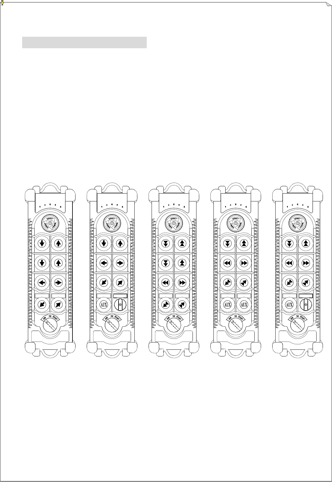
4.1.1 8-pushbutton types
4008-1: 8 single speed pushbuttons
4008-1S: 7 single speed pushbuttons + 1 selector switch
4008-2: 8 double speed pushbuttons
4008-3: 6 double speed pushbuttons + 2 single speed pushbuttons
4008-3S: 6 double speed pushbuttons + 1 single speed pushbutton + 1 selector switch
- 4 -
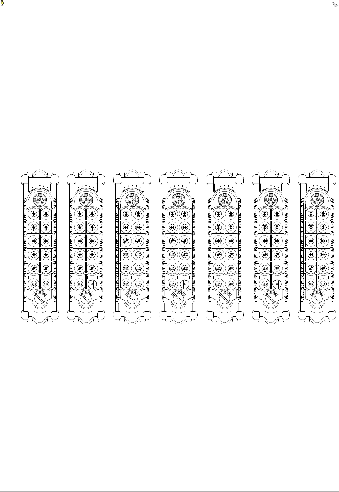
4.1.2 12-pushbutton types
4012-1: 12 single speed pushbuttons
4012-1S: 11 single speed pushbuttons + 1 selector switch
4012-2: 6 double speed pushbuttons + 6 single speed pushbuttons
4012-2S: 6 double speed pushbuttons + 5 single speed pushbuttons + 1 selector switch
4012-3: 8 double speed pushbuttons + 4 single speed pushbuttons
4012-3S: 8 double speed pushbuttons + 3 single speed pushbuttons + 1 selector switch
4012-4: 10 double speed pushbuttons + 2 single speed pushbuttons
- 5 -
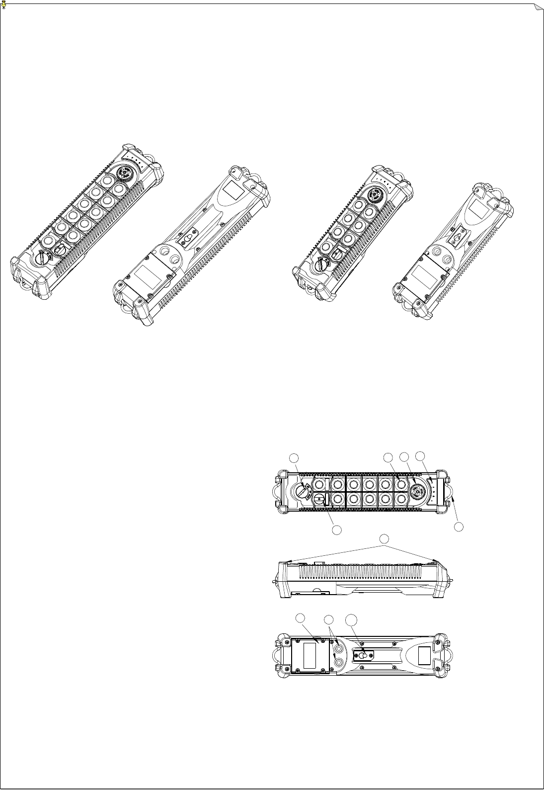
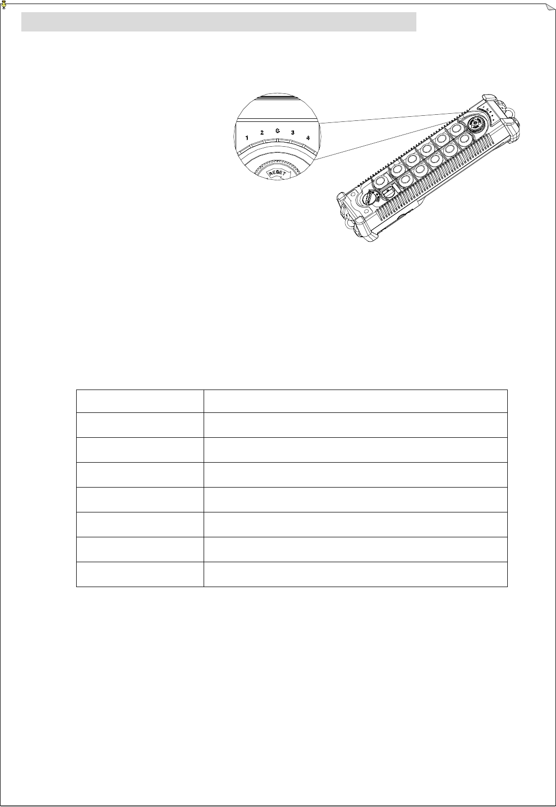
4.2 Transmitter Outline
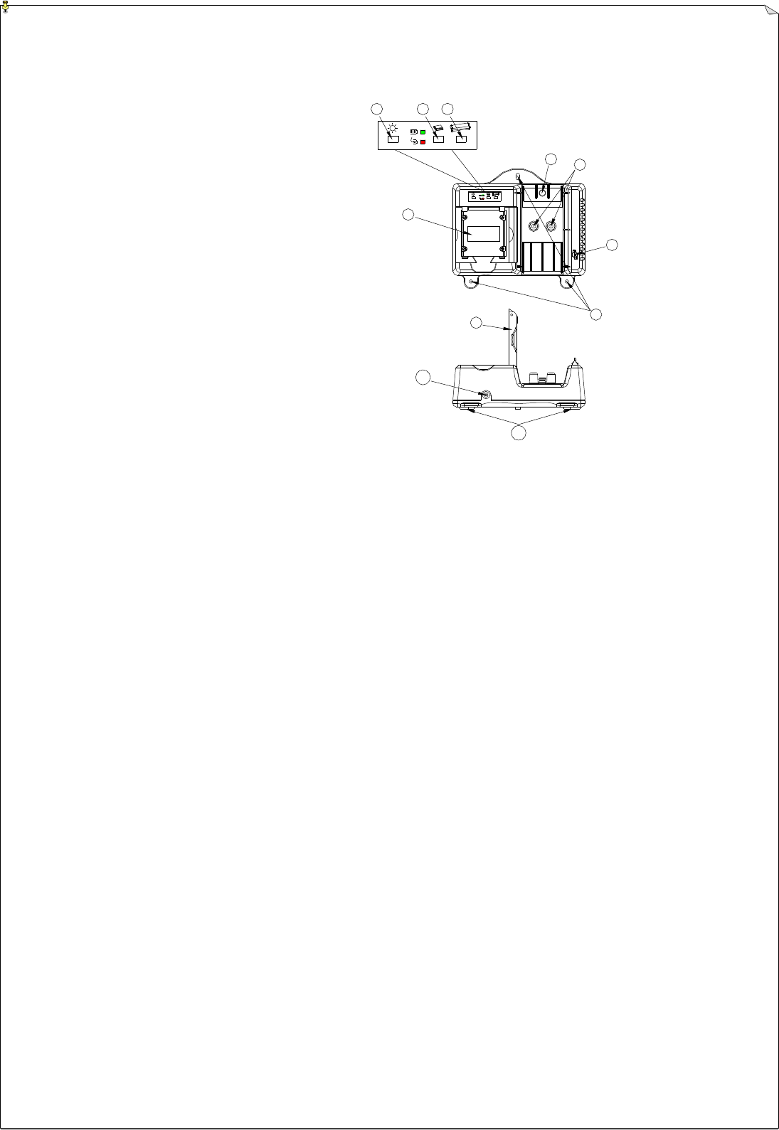
4.2.1 Transmitter External Descriptions
12 pushbuttons: 272mm × 65mm × 52mm 8 pushbuttons: 231mm × 65mm × 52mm
(Fig. 1) Transmitter Top / Bottom View
1. On / Off switch
2. function key
3. Emergency Stop Button (EMS)
4. Status LED Display
5. Shoulder Strap holder
6. Selector Switch
7. Anti-hit rubber
8. Lithium battery
9. Battery charging slot
10 Battery charging fixing hole
(Fig. 2) Transmitter Exterior Views
- 6 -
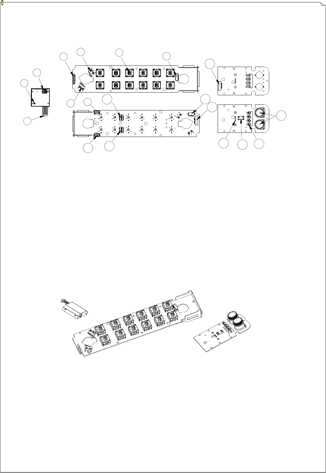
4.2.3 Encoder Board, TX Module, Recharging chip card and Rechargeable Battery Descriptions:
(Fig. 3) Encoder Board, RF Module, Power Card Descriptions
1.Transmitting channel
dip-switch 5. Start Switch
9.LED Display cable
port 13.Transmitting RF
module cable port 17.Chip Card Holder
2. Adjustable capacitor
for PLL frequency
compensation
6. One/Two speed
pushbutton 10.AUX dip-switch 14. ID code dip-switch 18.Battery pack contact
spring
3.Transmitting RF
module cable 7. Emergency Stop
Pushbutton (EMS) 11.Micro-Processor
Programming Port 15.Battery charging
board to encoder
board cable port
19.Battery charging
wiring loop holder
4.Port of Encoder board
to battery charging
board port
8. Power
Switch(ON/OFF)
12.Extra 2 aux.
pushbuttons and
selector switch
cable connector
16.Chip card special
setting port
(Fig. 4) Encoder Board, TX Module and Power Card Interior Descriptions
- 7 -
4.2.4 Battery Charger Exterior Descriptions
1. Lithium charging holder
2. Power Status LED
3. Low Battery Charging Status LED
4. Transmitter Charging Status LED
5. Transmitter Charging Fixing Pole
6. Transmitter Charging Pole
7. Cleaning Tool for Charging Hole
8. Battery Charger Fixing Holes
9. Lithium Battery Cover
10 Power Socket
11.Anti-Slippery Pads
(Fig. 2) Battery Charger Exterior
Descriptions
- 7 -
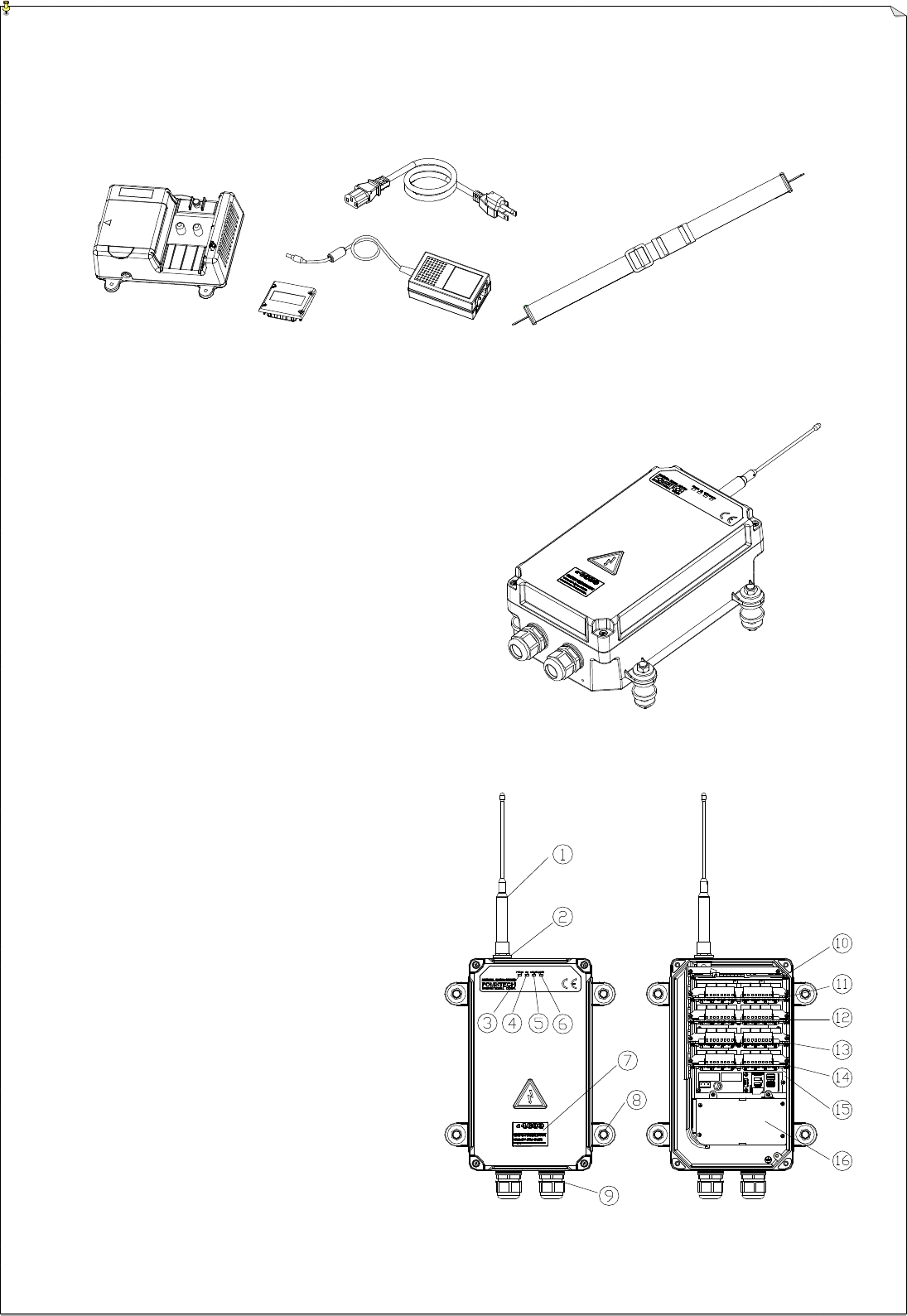
4.2.4 Rechargeable BatteryBattery Charger and Shoulder Strap Outline
(Fig. 5) Rechargeable BatteryBattery Charger and Shoulder Strap Outline
4.3 Receiver Introductions
4.3.1 Receiver Outline
300mm × 171mm × 115mm
(Antenna and Plug-in Socket Excluded)
(Fig. 6) Receiver Outline
4.3.2 Receiver Exterior Descriptions:
1. Antenna
2. Antenna holder
3. Receiver power source indicator
4. Receiver RF signal indicator
5. Receiver status indicator
6. Receiver main indicator
7. Model / Specification label
8. Anti-vibration fixing pole*4
9. cable gland*2
10.RX module card
11.Output relay card I
12.Output relay card II
13.Output relay card III
14.Output relay card IV
15.Decoder card
16.Power supply card
(Fig.7) Receiver External Descriptions
- 8 -
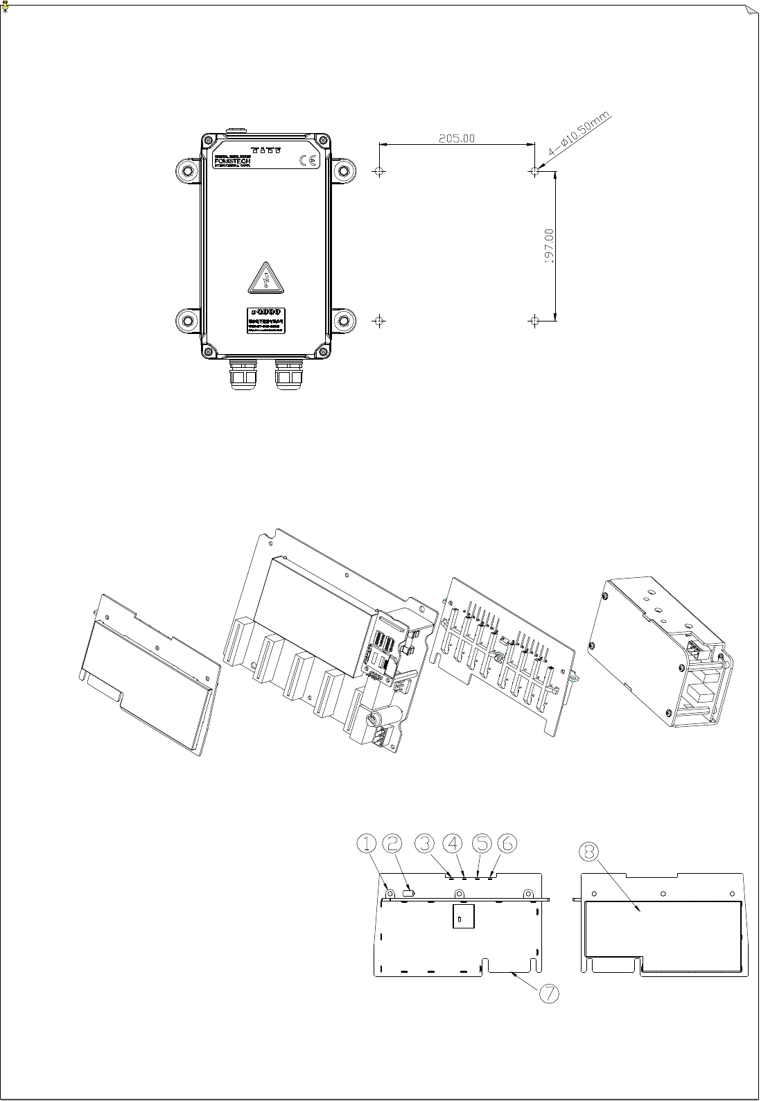
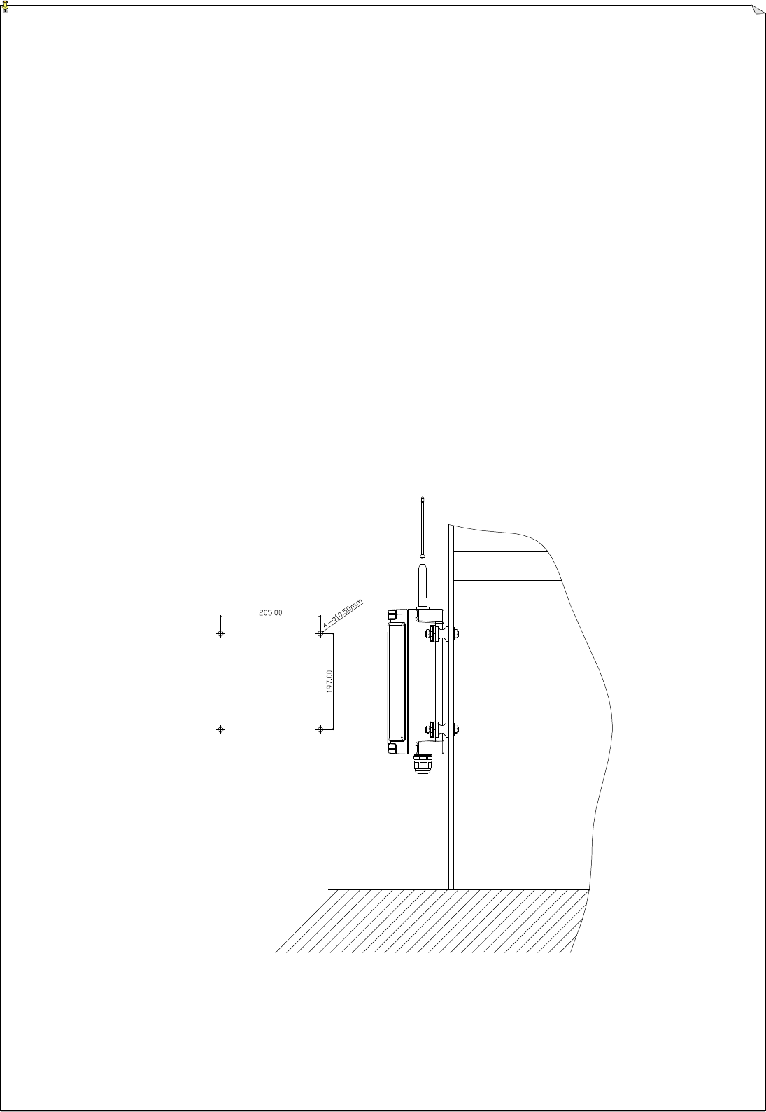
4.3.3 Receiver Mounting Dimension
(fig.8) Receiver Mounting Dimension
4.3.4 (1) RX Module Card
(2) Decoder Card (3) Output Relay Card
(4)
Power Supply Card
(fig.9)
(1) RX Module
1. RX module card fixing holder
2. Antenna port
3. Receiver main indicator
4. Receiver status indicator
5. Receiver signal indicator
6. Receiver power source indicator
7. RX module edge connector
8. RX module shielding plate
(Fig. 10)
RX module
- 9 -
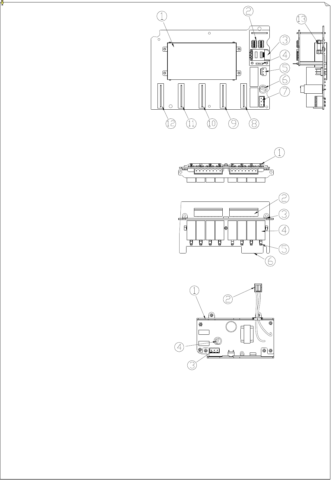
(2) Decoder card
(Fig. 11)
1. Decoder card shielding plate
2.
3.
4.
5.
6.
7.
8.
9.
10.
11.
12.RX module edge connector
13.
(Fig. 11) Decoder card
(3) Relay card (Fig.12)
1. Relay light pipe LED
2. Relay contact
3. Relay fixing holder
4. Relay
5. Relay indicator
6. Relay card edge connector
(Fig. 12) Relay card
(4)
Power board
(Fig. 13)
1. Power board aluminum holder
2.
3.
4.
4.4 Output Wiring diagram
(Fig. 13) Power Board
Enclosed inside receiver enclosure lid
- 10 -
5. SYSTEM SETTINGS
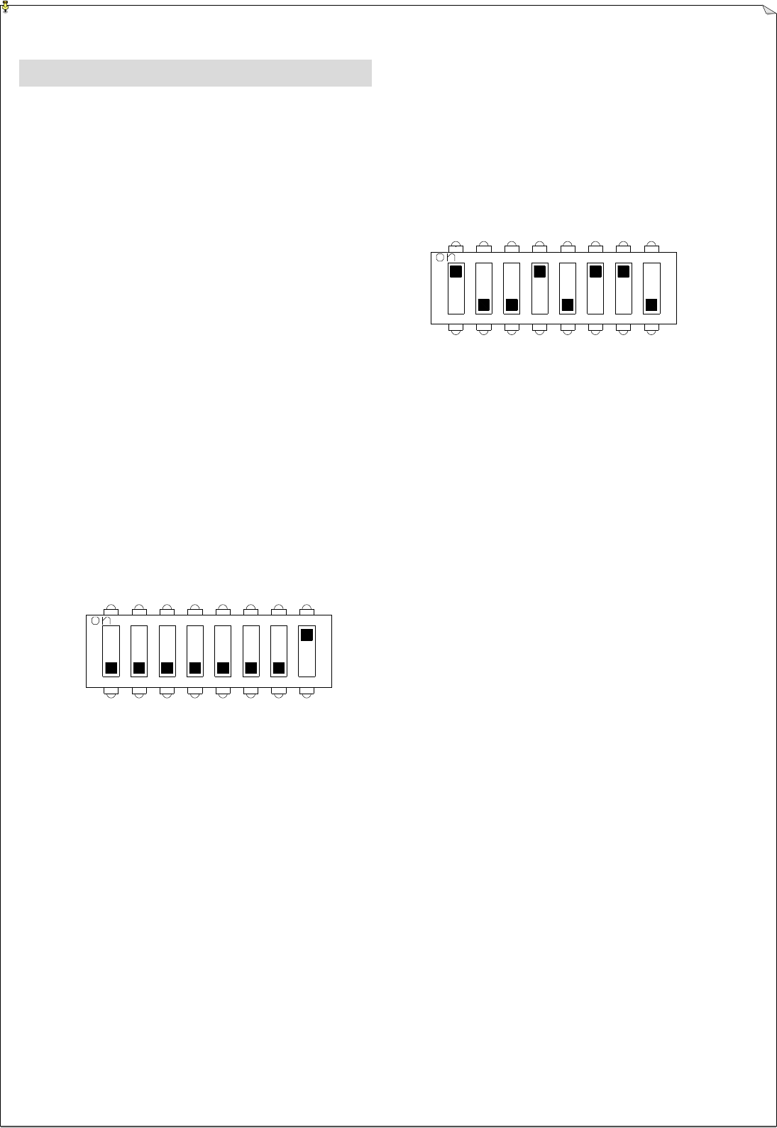
5.1 Transmitter ID Code Settings
Transmitter ID code are set via an 8-position dip-switch located on the encoder board (refer to fig.3 on
page 6)
Example: ID code → 10010110
Top location: “1” (fig.14) dip switch
Bottom location: “0”
Transmitter Frequency Channel Settings
The transmitter frequency channel is also set via an 8-position dip-switch located on the encoder
board (refer to fig.3 on page 6)
Example: frequency 433.075MHZ/channel 01(00000001)
(fig.15) frequency dip switch
Top location: “1” Bottom location: “0”
5.3 Transmitter Function Settings:
Not yet available.

- 11 -
5.4 Frequency Channel Table
FREQUENCY DIP-SWITCH SETTING CHANNEL
433.075 MHz 00000001 01
433.100 MHz 00000010 02
433.125 MHz 00000011 03
433.150 MHz 00000100 04
433.175 MHz 00000101 05
433.200 MHz 00000110 06
433.225 MHz 00000111 07
433.250 MHz 00001000 08
433.275 MHz 00001001 09
433.300 MHz 00001010 10
433.825 MHz 00001011 11
433.850 MHz 00001100 12
433.875 MHz 00001101 13
433.900 MHz 00001110 14
433.925 MHz 00001111 15
433.950 MHz 00010000 16
433.975 MHz 00010001 17
434.000 MHz 00010010 18
434.025 MHz 00010011 19
434.050 MHz 00010100 20
- 12 -
6 RECEIVER INSTALLATION
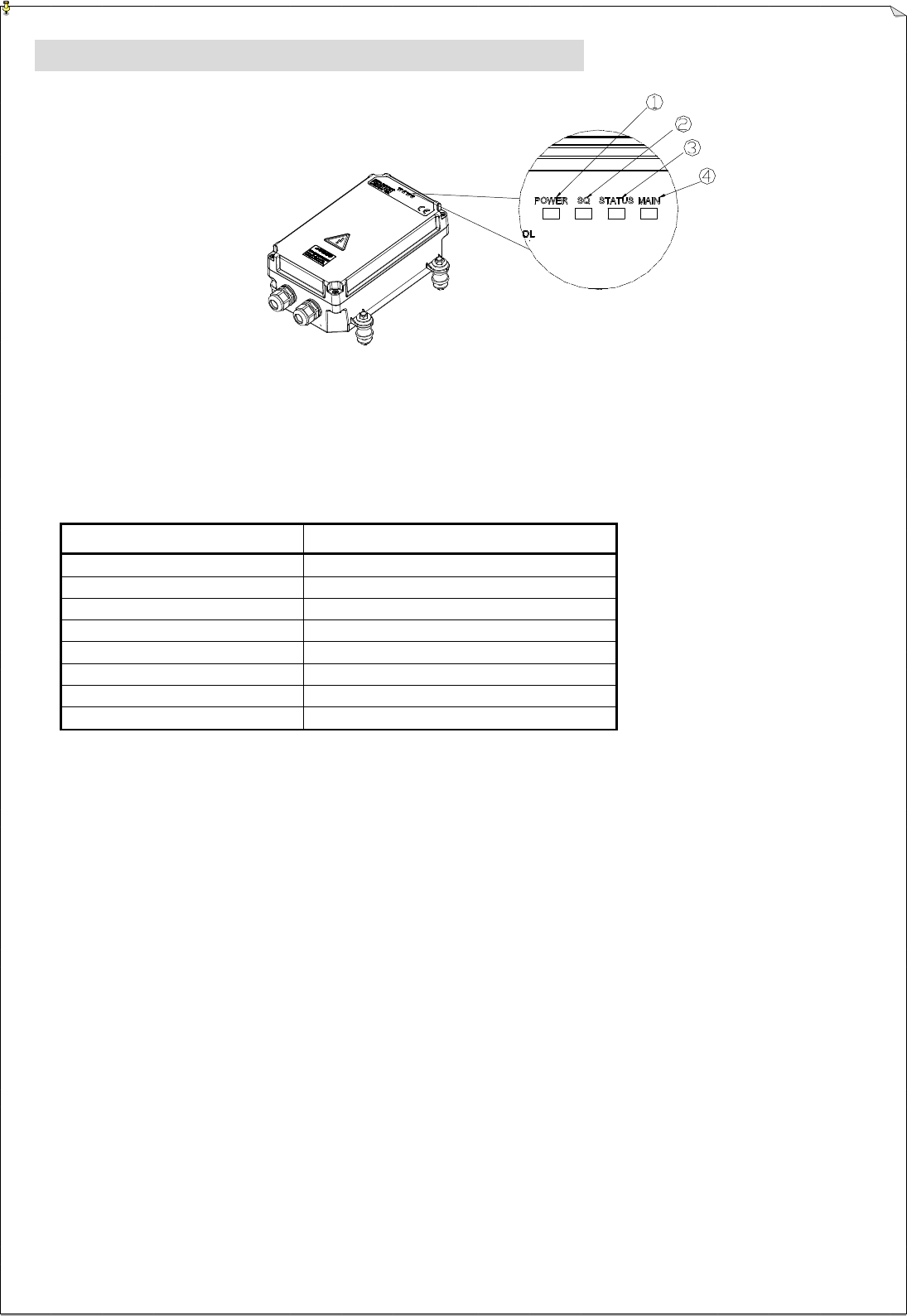
6.1 Receiver Status LED Displays
Receiver Status LED Display
(Fig 17) Receiver Status LED Display
1. Receiver Power Display 3. Receiver Status Display
2. Receiver SQ Status Display 4. Receiver MAIN Display
2. Receiver Central CPU Status LED Display
LED INDICATION REASON
Slow Blinks (Green) Standby
Fast Blinks (Green) Transmitted signals received
Fast Blinks (Red) MAIN contact relays jammed or defective
3 Fast Blinks (Red) RX module defective
4 Fast Blinks (Red) EEPROM error
5 Fast Blinks (Red) Incorrect transmitted ID code
6 Fast Blinks (Red) Incorrect system type
Slow Blinks (Green) Standby
6.2 Preparation
1. Required Tools:
(1) Flat Head Screwdriver (-) (6) Power Drill with φ10.5 ~φ11 Drill-Bit
(2) 5mm Wrench X 6 (7)
Long nose plier
(3) Multi-Meters (8)
Cutter plier
(4) Box end wrench or 14 Wrench X 2
(5) Power Drill
(9) Output Cables (φ12.5 ~φ19.5 ) and wiring
materials
2. Ensure receiver is not set to the same frequency channel and ID code as any other units in use at
the same facility or within distance of 300 meters.
3. Prior to installation, make sure that the crane system itself is working properly.
4. Use the multi-meter to check the voltage source available and ensure receiver voltage setting is correct for this
voltage.
5. Prior to installation, switch off the main power source to the equipment.
- 13 -
6.3 Step-by-Step Receiver Installation
1. Decide system wiring first for cable arrangement. If cable gland is used, please stuff those cable
glands which are not used. (All the cable glands are stuffed prior to the shipment.)
2. Select a suitable wiring location:
(1) The location selected should have the antenna visible from all areas where the receiver is fixed.
(2) Select the location which is far from high voltage wiring or equipment, e.g. motor, relay…etc.
(3) The location selected should not be blocked. Coaxial cable is suggested to be used to move the
location of antenna if needed.
(4) Please refer to Fig. 18 Receiver Mounting Size for the selection of better installing location.
3. Please refer to Fig. 18 Anti-Vibration Spring Location. Drill 4 fixing holes (11mm).
* Note: The higher the receiver, the better.
4. Tighten 4 screws provided on receiver.
5. Power cable has to be connected to AC position and ground cable has to be connected to GND
position. It is also acceptable to connect ground cable to screw fixing hole on receiver.
6. Ensure all wiring is correct and safely secured and all screws are fastened.
(Fig. 18) Receiver mounting size
- 14 -
7. TRANSMITTER INSTALLATION
1. Transmitter LED Display
(Fig 19) Transmitter LED Display
(1) Battery Power LED Display: green light for having enough power, read light for insufficient power.
(2) Transmitter Status LED Display: green light for normal status, red light for abnormal status.
3. Transmitter Status LED Display:
STATUS DISPLAY REASON
No Light Displayed Transmitter in sleep mode with receiver MAIN relay deactivated
Slow Blinks (Green) Transmitter on standby
Fast Blinks (Green) Transmitter active
Constant Red Light Jammed or defective pushbutton, switch or joystick contacts
Fast Blinks (Red) The contact point currently in use is operative (refer to note A)
3 Fast Blinks (Red) PLL TX module defective
4 Fast Blinks (Red) EEPROM error
Note A: When there is a defective or jammed pushbutton, switch or joystick contacts, the transmitter status LED will display a constant
red light without flashes. To find out which contact is defective or jammed, activate each pushbuttons, switches or joysticks a
step at a time by holding at each position for up to 2 seconds. If a flashing red light (blinks rapidly) is displayed at a specific
position, it means that the contact point for that particular position is operative. If the lights remained constantly red at a
certain position, then it means that this position’s contact is either jammed or defective. The main purpose of function is to let
the user realize which contact on the transmitter is not working properly and required service immediately.

- 15 -
4. Transmitter Battery Power LED Display
POWER DISPLAY
REASON
Constant Green Battery level normal
Slow blinking Red 1. Low battery power (1
st
warning)
2. Battery below average. Replace battery immediately.
Fast blinking Red 1. Low battery power (2nd warning)
2. Transmitter unit will stop transmitting at anytime
Constant Red 1. Low battery power (3rd warning)
2. Transmitter power and receiver MAIN relay deactivated

- 16 -
BATTERY CHARGING
1. Plug in the power cord and the power indicator will light up.
2. When a battery pack is inserted, the green charging light will blink to indicate charging is taking place at the
current moment.
3. If discharging of battery pack is desire, press the “DISCHARGE” button. (Discharged voltage about 30mA)
At discharging mode, the green blinking light will now turned into a constant red light indicating that the
battery pack is now being discharged. If you want to cancel the discharge, just press “DISCHARGE” button
again.
4. When discharging is completed, the charger will automatically switch to the charging mode where the green
blinking light will reappear again.
5. The charging time for a 600mA NiCd battery pack is approximately 3 ~ 6 hours. As for the 1450mA NiMH
battery pack, the charging time is approximately 7 ~ 9 hours.
6. When charging is completed, a constant green light will appear to indicate that the battery pack is fully charged.
(Battery tepid is normal)
7. When the battery pack is at 90% charged state, trickle charging will take over to ensure the longevity of the
battery pack and as well as to ensure the battery pack is 100% charged.
8. When the battery pack’s temperature exceeds 50 , the charger will go into protective mode and charging will
be discontinued.
9. To prolong the life of the battery pack, it is recommended that the battery pack be fully discharged prior to
every re-charging.
Order
Status Display Reason LED Display Status
1 Charge Hang the transmitter on the
charger Refer to (charger LED display)
2 CPU I/O error
Set the 47k ground resistor on
CPU I/O button open. Red light ON_0.1 sec./OFF_0.3 sec. 8 times,
OFF_0.8 sec.
3 2
nd
warning Lithium battery 2.8V or
regular 2.4V turns all the
power off
Red light ON_0.1 sec./OFF_0.3 sec. twice,
OFF_0.8 sec.
4 EEPROM fails EEPROM data write-in fail
Red light ON_0.1 sec./OFF_0.3 sec. 7 times,
OFF_0.8 sec.
5 Chip card fails (not
inserted) No chip card or write-in error
Red light ON_0.1 sec./OFF_0.3 sec. 5 times,
OFF_0.8 sec.
6 Chip card data error
Chip card data does not match
data in CRC 8. System type
is not identical.
Red light ON_0.1 sec./OFF_0.3 sec. 6 times,
OFF_0.8 sec.
7 TX module fails RF module error tested by
encoder Red light ON_0.1 sec./OFF_0.3 sec. 4 times,
OFF_0.8 sec.
8 Pushbuttons locked Power on when part of the
pushbuttons are connected Red light ON_0.1 sec./OFF_0.3 sec. 3 times,
OFF_0.8 sec.
- 17 -
9 STOP status or POS
activates Depress STOP button or
power switch OFF
10 STOP status and
function button is
depressed
Depress STOP button and
then function buttons
Red light ON_0.1 sec., OFF_0.1 sec. blinks
11 1
st
warning Lithium battery 3.2V or
regular 3.0V Red light ON_0.1 sec., OFF_0.9 sec. blinks
12 Regular power on Normal voltage. Some
buttons are not depressed 0.2 sec. red light S→(2+S+3) →(1+2+S+3+4)
→green light S→(2+S+3) →(1+2+S+3+4)
13 operating TX board sends signal
remittently or continuously Green light ON_0.1 sec., OFF_0.1 sec. blinks
14 Standby status Without sending signals
remittently or continuously Green light ON_0.1 sec., OFF_0.9 sec. blinks
15 Chip card updated CRC in chip card changed
CRC 0.5 sec. green light 1→(1+2)→(1+2+S)
→(1+2+S+3) →(1+2+S+3+4)
16 Copy data in CPU to
chip card JP2 short 0.5 sec. green light 4→(3+4)→(S+3+4)
→(2+S+3+4) →(1+2+S+3+4)
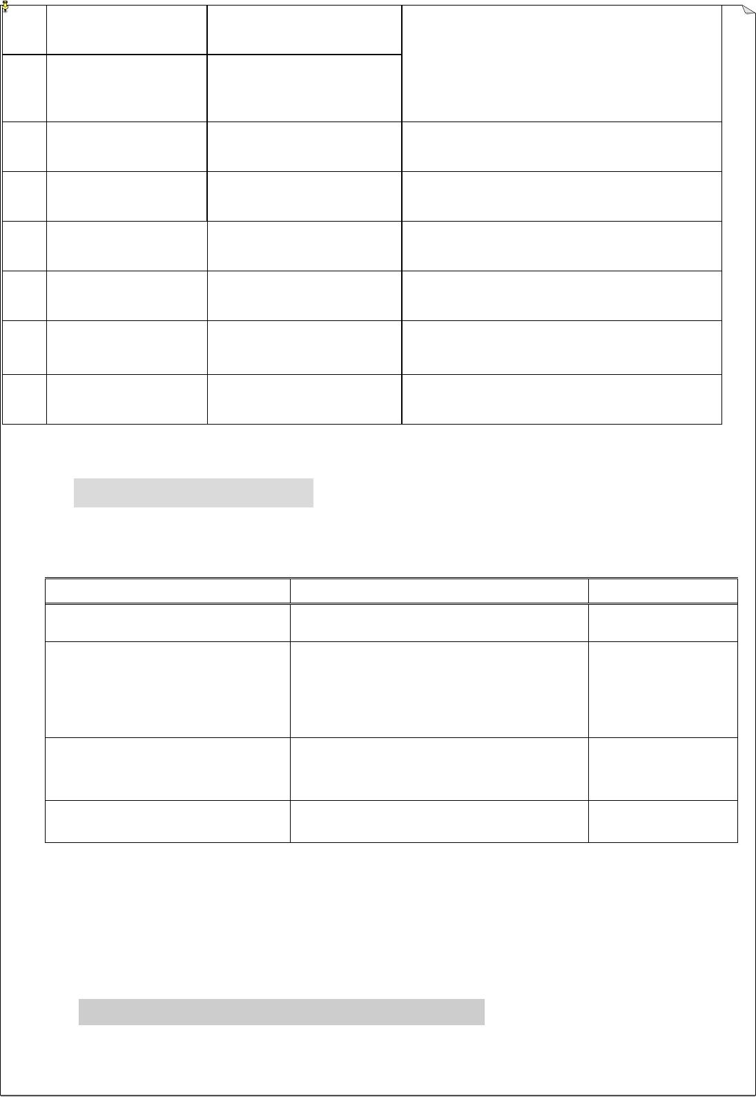
TROUBLE SHOOTING
Should the operator find the equipment not operating normally, please check the chart below for simple tr
ouble shooting tips.
PROBLEM POSSIBLE REASON SOLUTION
Transmitter does not communicate
with the receiver Use pendant handset to operate but not
work Repair crane
1. Transmitter is not turned on
2. Transmitter low battery power 1. Battery and status LED does not lit
2. Turn on the transmitter power. Release
EMS button and battery indicator
constantly red
1.Turn on the
power
2.Replace recharge-
able battery
No power to the receiver (AC
power indicator on the receiver
unit not lit)
Check if the receiver power board is lit,
if
not
Ensure receiver
is correctly wired
Receiver fuse burn down Check if receiver fuse is burn down, if
so
Replace fuse
10.SYSTEM SPECIFICATION

- 18 -
Transmitter Unit
Frequency Range : PLL 433MHz
Transmitting Range: : 70 Meters
Continuous Operating Time : 8 Hours
Security ID Code : 65,536 sets (16 + 1 bit)
Channel Spacing : 25KHz
Hamming Distance : D 4 + CRC8
Frequency Control : Quartz Crystals (PLL)
Frequency Drift : < 5ppm @ -10 ~ 70
Frequency Deviation : < 1ppm @ 25
Spurious Emission : > 50dBc
Transmitting Power : ~1.0mW
Emission : F1D
Antenna Impedance : 50 ohms
Enclosure Rating : IP-66
Source Voltage : 4.2VDC lithium / 1800mA
Current Drain : ~20mA@3.7V
Operating Temperature : -10 ~ 70
Dimension : 273mm X 65mm X 52mm (12 pushbuttons)
228mm X 65mm X 52mm (8 pushbuttons)
Weight : 615g (with 1800mA lithium battery)
Note: Longer or shorter transmitting ranges are available upon request.
Receiver Unit

- 19 -
Frequency Range : PLL 433 MHz
Channel Spacing : 25KHz
Hamming Distance : D
Frequency Control : RX module card or synthesizer (PLL)
Frequency Drift : < 5ppm @ -10 ~ 70
Frequency Deviation : < 1ppm @ 25
Sensitivity : < -125dBm
Antenna Impedance : 50 ohms
Data Decoder Reference : Quartz Crystals
Responding Time : 50mS ~ 150mS
Enclosure Rating : IP-66
Source Voltage : 100 ~ 240VAC @ 50/60 Hz. (standard equipped)
Power Consumption : MAX 32W@240VAC 50Hz
Operating Temperature : -10 ~ +75
Output Contact Rating : 250V @ 10A
Dimension : 300mm X 171mm X 115mm
Weight : 4,500g (without the output cable)
Note: Other types of source voltages are available upon request.

- 20 -
15.21 “Changes or modifications are not expressly approved by the manufacturer could
void the user's authority to operate the equipment. Changes or modifications to the
device may void FCC and CE compliance. In frequently used radio links should be tested
regularly to protect against undetected interference or fault.”
"Operation is subject to the following two conditions: (1) this device may not cause
interference, and (2) this device must accept any interference, including interference that
may cause undesired operation of the device."