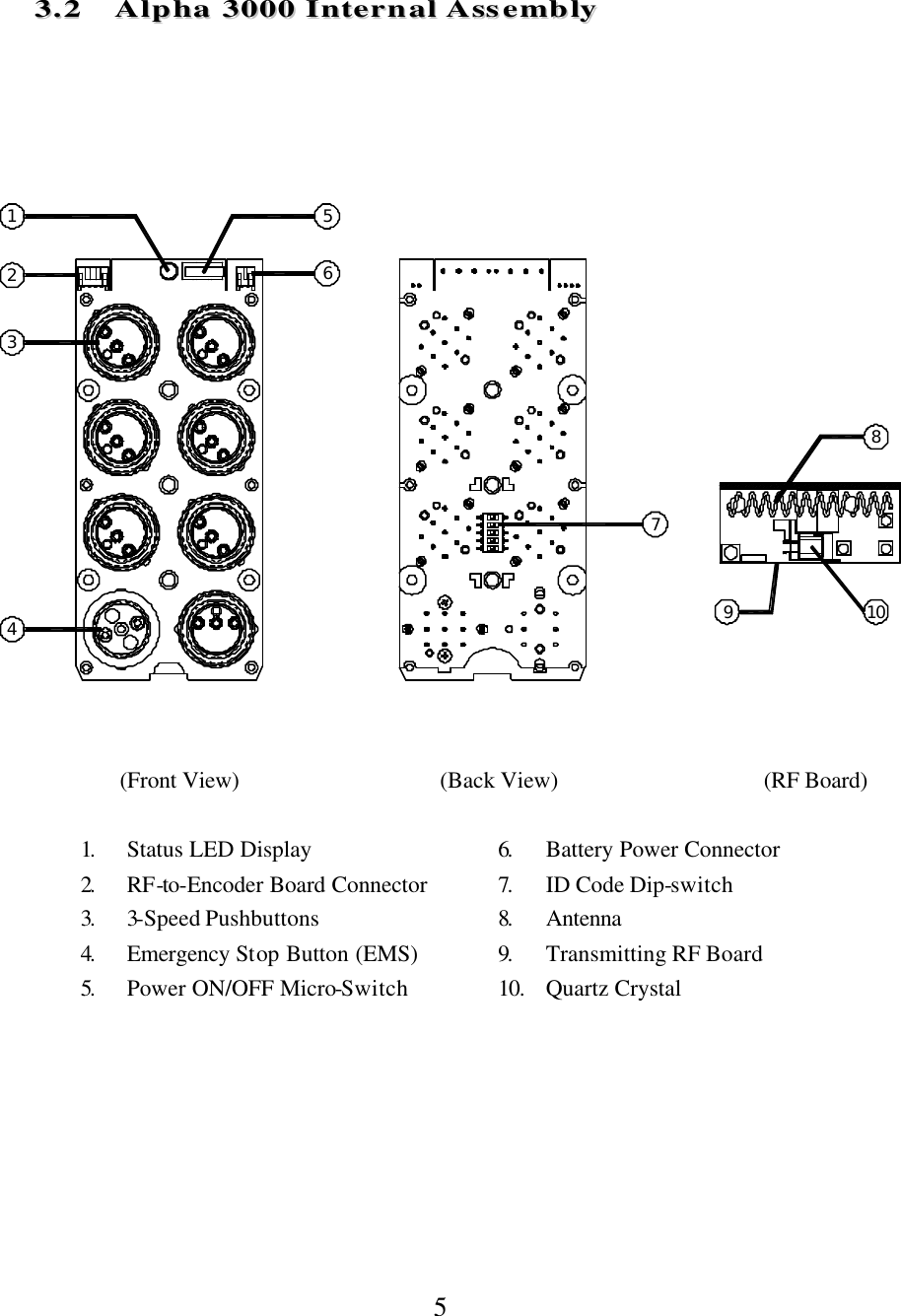
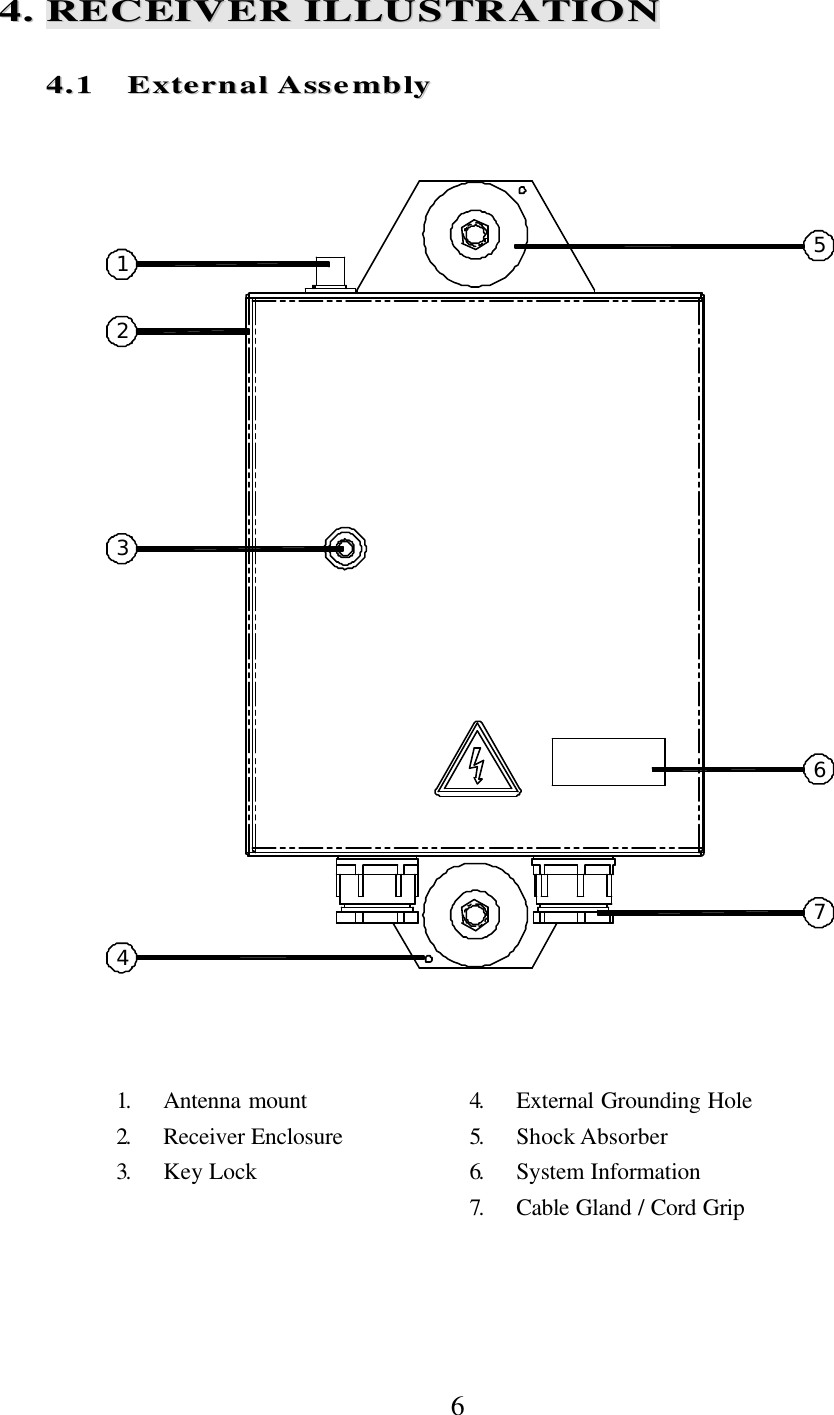
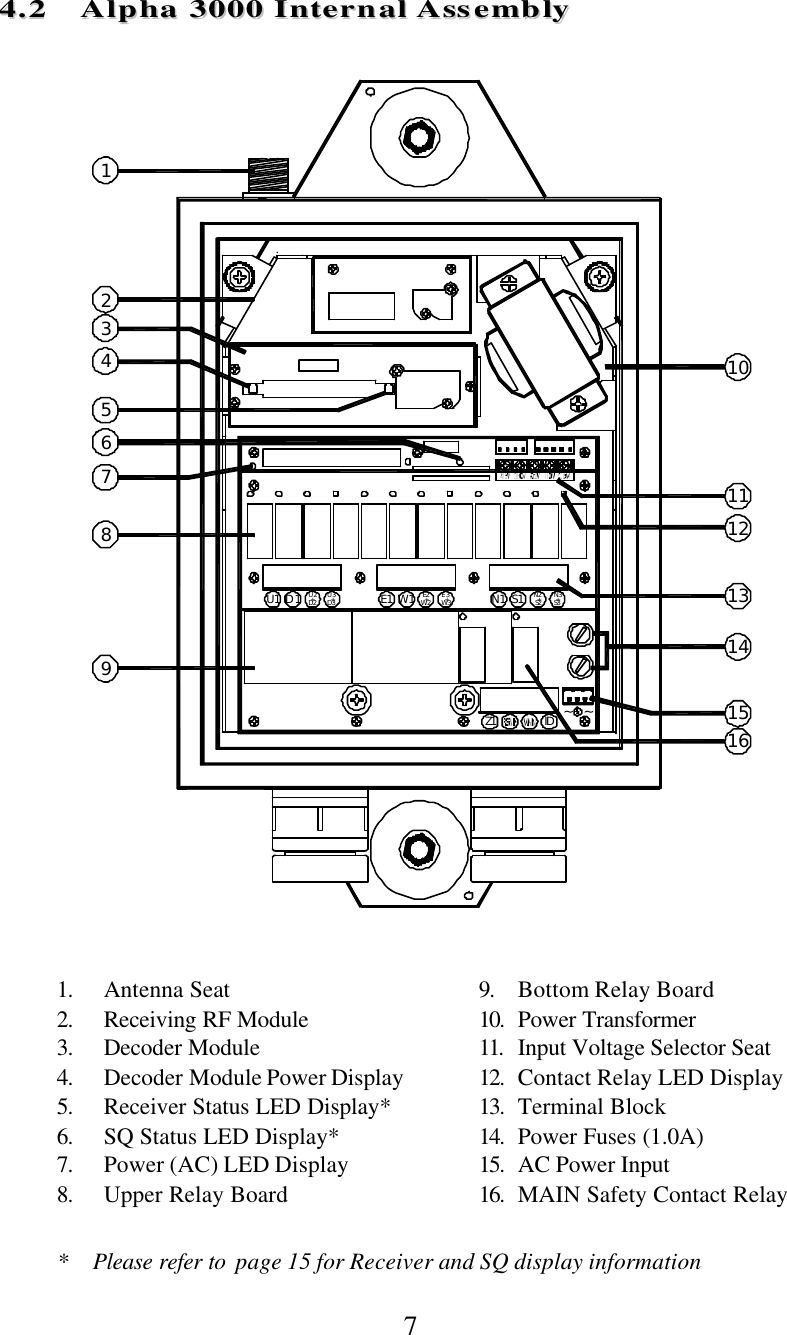
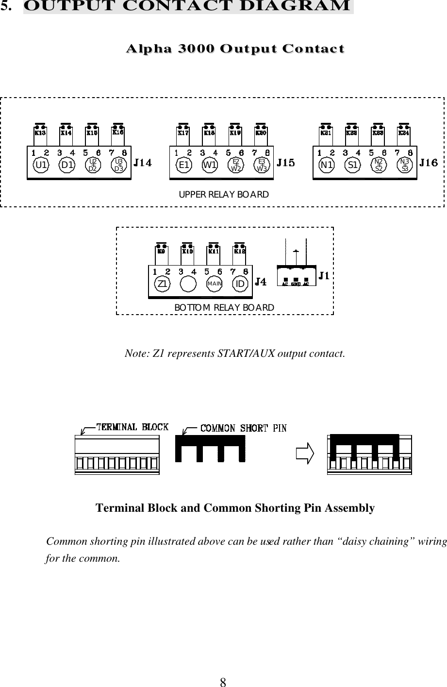
Fomotech ALPHA3000MODEL Industrial Radio Remote Control User Manual Manual

Fomotech International Corp. Industrial Radio Remote Control Manual

Exhibit D Users Manual per 2 1033 b3

 1   TTAABBLLEE  OOFF  CCOONNTTEENNTTSS     Page    1.  INTRODUCTION  .......................................................................................................   2 2.  SAFETY INSTRUCTION .............................................................................................   3 3.  TRANSMITTER ILLUSTRATION 3.1 Alpha 3000 External Assembly ......................................................................... 4 3.2 Alpha 3000 Internal Assembly  .........................................................................   5 4.  RECEIVER ILLUSTRATION 4.1 External Assembly ...............................................................................................   6 4.2 Alpha 3000 Internal Assembly  ......................................................................... 7 5.  OUTPUT CONTACT DIAGRAM   Alpha 3000 Output Contact ............................................................................. 8 6.  SYSTEM CONFIGURATIONS  6.1 Jumper Settings ................................................................................................... 9 6.2 Security ID Code Settings .....................................................................................   10 6.3 Pushbutton Contact Settings .................................................................................   11   6.4 Voltage Settings .....................................................................................................   11 7.  RECEIVER INSTALLATION     7.1 Preparation For Installation  ...................................................................................   12 7.2 Step By Step Installation ....................................................................................... 12 7.3 System Testing ....................................................................................................... 13 8.  TRANSMITTER OPERATION  ................................................................................... 14 9.  TROUBLE SHOOTING  ............................................................................................... 15 10. SYSTEM SPECIFICATION ......................................................................................... 16 11. PARTS LIST ................................................................................................................. 17
 2 11..  IINNTTRROODDUUCCTTIIOONN   The Alpha 3000 System is a highly reliable industrial radio remote control system.  The versatile features of the Alpha 3000 system permit its use in many different remote control applications that required 3-step control.  The system can be used to control factory cranes, multiple hoists, trolleys, mining equipment, building construction equipment, automatic control systems, and many others.  The Alpha 3000 Radio Remote Control System incorporates numerous redundant safety circuits that guaranty maximum security and ensure the system is resistant to outside interference.  The major features of the Alpha 3000 system are as follow:  * The system uses advanced microprocessors with highly evolved software that has redundant error checking and correcting capabilities to ensure 100% error-free transmission, decoding, and control of all output relays.  This highly evolved software includes CRC (cyclical redundancy check codes) and Hamming Codes (error recovery).  * To insure maximum operating safety, the Alpha 3000 system incorporates numerous safety features.  Some of these built-in safety features include transmitter pushbutton self-diagnosing, transmitter low-voltage detection and warning, receiver self-diagnosing, and MAIN deactivation when the system is in sleep mode.      * The  transmitter encoder and receiver decoder both utilize advanced microprocessor control.  The availability of 65,536 sets of unique ID codes will ensure that only commands from the matching control transmitter can be carried out without any interference from other radio systems.    * For added safety, the system also incorporates special Safety MAIN Relay.  If the Safety MAIN Relay is defective (fails to open or close during operation), it will signal the system to shut down immediately to avoid the possibility of any accidents occurring.     * Water-resistant transmitter and receiver enclosures.     The Alpha 3000 Radio Remote Control System consists of a water-resistant handheld transmitter and receiver.  The transmitter casing is molded using industrial strength composite materials which are impervious to dust, water, oil, acids, alkaline, heat and sunlight as well as being resistant to deformation due to long term use in harsh environments.  The industry’s best 3-step pushbuttons are also constructed from industrial strength composite materials with a minimum of up to one million press cycles.  For power savings, the transmitter is designed with an ultra high efficiency power saving circuit that requires only four “AA” size alkaline batteries for more than 200 hours of continuos operation between replacements.
 3 22..  SSAAFFEETTYY  IINNSSTTRRUUCCTTIIOONN   The Alpha 3000 system is relatively simple to use, however, it is very important to observe the proper safety procedures before, during, and after operation.  When used properly our Alpha 3000 radio remote controls will enhance safety, productivity and efficiency in the workplace.  The following procedures should be strictly followed:  1.  Check the transmitter casing and pushbuttons daily.  Should any damage that could inhibit the proper operation of the transmitter be found the unit should be immediately removed from service.     2.  The transmitter voltage should be checked on a daily basis.  If the voltage is low (red status light blinking, refer to section 8 on page 14), the four “AA” alkaline batteries should be replaced.    3.  The red mushroom type emergency stop button (EMS) should be checked at the beginning of each shift to ensure it is in proper working order and the Stop command is being received.  4.  In the event of an emergency, depress the emergency stop button (EMS) immediately to disengage the receiver MAIN and the transmitter power.  Then turned the power “off” from the main power source to the crane or equipment.    5.  The transmitter power key switch should be pulled “off” after each use and should never leave the transmitter in the power “on” position when the unit is unattended.   6.  Do not use the same channel and ID code as any other system in use at the same facility or within 600 feet.  7.  Ensure the shoulder strap is worn at all time during operation to avoid accidental damage to the transmitter.  8.  Never operate a crane or equipment with two transmitter units at the same time with the same channel and ID code.    FCC ID: LZ6ALPHA3000MODEL This device complies with Part 15 of the FCC Rules.  Operation is subject to the following two conditions; (1) this device may not cause harmful interference, and (2) this device must accept any interference receiv ed, including interference that may cause undesired operations.
 4 124567891011121314151617333..  TTRRAANNSSMMIITTTTEERR  IILLLLUUSSTTRRAATTIIOONN   33..11  AAllpphhaa  33000000  EExxtteerrnnaall  AAsssseemmbbllyy                       (Front Few)          (Back View)  1.  Transmitter Unit     9.  Pushbutton #1 (Up)  2.  Status LED Display*        10. Pushbutton #3 (East) 3.  Spare Power Key Switch    11. Pushbutton #5 (North) 4.  Pushbutton #2 (Down)    12. START/AUX Pushbutton 5.  Pushbutton #4 (West)    13. System Information 6.  Pushbutton #6 (South)     14. Shoulder Strap Ring 7.  Emergency Stop (EMS)    15. FCC/IC Label 8.  Power Key Switch     16. Battery Cover          17. Warning Label     * Please refer to page14 for Transmitter Status LED information
 5   33..22  AAllpphhaa  33000000  IInntteerrnnaall  AAsssseemmbbllyy                (Front View)          (Back View)          (RF Board)  1.  Status LED Display     6.  Battery Power Connector 2.  RF-to-Encoder Board Connector    7.  ID Code Dip-switch 3.  3-Speed Pushbuttons    8.  Antenna 4.  Emergency Stop Button (EMS)    9.  Transmitting RF Board 5.  Power ON/OFF Micro-Switch    10. Quartz Crystal         56714381092
 6 562314744..  RREECCEEIIVVEERR  IILLLLUUSSTTRRAATTIIOONN   44..11  EExxtteerrnnaall  AAsssseemmbbllyy                                1.  Antenna mount    4.  External Grounding Hole 2.  Receiver Enclosure   5.  Shock Absorber 3.  Key Lock     6.  System Information 7.  Cable Gland / Cord Grip
 7 Z1 ~123891011IDS1N1 N3+S3N2+S2W1E1U3+D3U2+D2D1U1 E2+W2 E3+W3~71213141516654  44..22  AAllpphhaa  33000000  IInntteerrnnaall  AAsssseemmbbllyy                             1. Antenna Seat 9. Bottom Relay Board 2. Receiving RF Module 10.  Power Transformer 3. Decoder Module 11.  Input Voltage Selector Seat 4. Decoder Module Power Display   12.  Contact Relay LED Display 5. Receiver Status LED Display* 13.  Terminal Block 6. SQ Status LED Display* 14.  Power Fuses (1.0A)  7. Power (AC) LED Display 15.  AC Power Input  8. Upper Relay Board 16.  MAIN Safety Contact Relay   * Please refer to  page 15 for Receiver and SQ display information
 8 U1 D1 U2+D2 U3+D3 E1 W1 E2+W2 E3+W3 N1 S1 N2+S2 N3+S3MAINZ1UPPER RELAY BOARDBOTTOM RELAY BOARDID5. OUTPUT CONTACT DIAGRAM  AAllpphhaa  33000000  OOuuttppuutt  CCoonnttaacctt   Note: Z1 represents START/AUX output contact.     Terminal Block and Common Shorting Pin Assembly   Common shorting pin illustrated above can be used rather than “daisy chaining” wiring for the common.
 9 JUMP66..  SSYYSSTTEEMM  CCOONNFFIIGGUURRAATTIIOONNSS    66..11  JJuummppeerr  SSeettttiinnggss      There are numerous functions that can be set via jumpers located inside the decoder module.  Please see the diagram and chart below on how to set these functions.                Manufacture Setting          Open After inserting the transmitter power key switch, or after EMS reset, press START/AUX pushbutton to activate the receiver MAIN. JP1 Short Insert the transmitter power key switch will immediately activates the  receiver MAIN.  After EMS reset, re-insert the power key switch to  reactivate the receiver MAIN.  Open  After 5 minutes of transmitter non-usage the receiver MAIN  will be deactivated (sleep mode). JP2 Short Sleep mode deactivated with receiver MAIN stays on constantly.  Open Pushbutton 1 ~ 6 interlocked. JP3 Short Pushbutton 1 ~ 6 non-interlocked with single speed contact. Open No acceleration delay from 1st through 3rd speed. JP4 Short Acceleration delay for up to 1 second from 1st through 3rd speed.  Note: Every time when you change jumper settings you must first turn the receiver power “off” and then turn it back “on” after setting so that they can be stored in memory.
 10     JP1  JP1 Open Insert the transmitter power key switch Press START/AUX Receiver MAIN activated or After EMS reset Press START/AUX Receiver MAIN activated JP1 Short Insert the transmitter power key switch Receiver MAIN activated or After EMS reset Re-insert the transmitter power key switch Receiver MAIN activated  JP2  JP2 Open After 5 minutes of transmitter non -usage   Receiver MAIN deactivated JP2 Short Receiver MAIN stays “on” constantly until the main power source of the system is turn “off”   JP3 JP3 Open Pushbutton 1 ~ 6 interlocked JP3 Short Pushbutton 1 ~ 6 non-interlocked with single speed contact   JP4  JP4 Open No acceleration delay from 1st  through 3rd speed JP4 Short 1st  speed depressed After 1 second 1st speed contact relay engaged 2nd speed depressed After 1 second 2nd speed contact relay engaged 3rd  speed depressed After 1 second 3rd  speed contact relay engaged    66..22  SSeeccuurriittyy  IIDD  CCooddee  SSeettttiinnggss    The ID code dip-switch is located on the backside of the encoder board (refer to item #7 on page 5) and on the top of the decoder module (see below).     Example : ID code  ? 10001100                             Top Location         ?  “1” Bottom Location   ?  “0”
 11 IDDIP SWITCH  66..33  PPuusshhbbuuttttoonn  CCoonnttaacctt  SSeettttiinnggss      The START/AUX pushbutton can be set either to normal or latching contact.  This function that can be set via an 8-position dip-switch located inside the decoder module (please refer to the diagram below).  By adjusting the dip setting either to the top or bottom slot will change the contact form of the pushbutton (please refer to the chart below).  Pus hbuttons are numbered from right-to-left and from top-to-bottom.        Top position    ?   “1” Bottom position    ?    “0”        Alpha 3000  DIP1 ? “0” ? Pushbutton 7 (START/AUX) with normal momentary contact                “1” ? Pushbutton 7 (START/AUX) with toggle / latching contact        66..44  VVoollttaaggee  SSeettttiinnggss   There are four different voltage settings available inside the Alpha 3000 receiver enclosure (bottom relay board), please select one that corresponds to the main power source of the crane or equipment.        Input Voltage Range Accepted:     1)  AC 110V ? From AC 100V ~ AC 120V  2)  AC 220V ? From AC 220V ~ AC 240V  3)  AC 380V ? From AC 380V ~ AC 400V  4)  AC 415V ? From AC 415V ~ AC 440V
 12 77..  RREECCEEIIVVEERR  IINNSSTTAALLLLAATTIIOONN    77..11  PPrreeppaarraattiioonn  FFoorr  IInnssttaallllaattiioonn   1.  Required Tools: (1) Flat Head Screwdriver (-) (2) Phillips Head Screwdriver (+) (3) Multi-Meter (4) Open End Wrench (5) Power Drill with 10.5mm ~ 11mm Drill-Bit  2.  Check to ensure that your receiver is not set to the same channel and ID code as any other systems in operation at the same facility within 600 feet.  3.  Prior to installation, make sure that the crane or equipment itself is working properly. 4.  Use a multi-meter to check the voltage source available and ensure that the receiver  voltage setting matches your power source. 5.  Prior to installation, switch “off” the main power source to the crane or equipment.  77..22  SStteepp  BByy  SStteepp  IInnssttaallllaattiioonn   1.  The location selected should have the antenna visible from all areas where the transmitter is to be used. 2.  The location selected should not be exposed to high levels of electrical noise. 3.  Ensure the selected location has adequate space to accommodate the receiver enclosure. 4.  Make sure the receiver unit is in upright position (vertical). 5.  The distance between the antenna and the control panel should be as far apart as possible. 6.  Drill two holes on the control panel (10.5mm).  Refer to diagrams next page. 7.  Tightened the bolt nuts provided. 8.  Ensure AC ground is connected to the power input terminal block, otherwise chassis ground should be connect to the chassis ground connection hole on the receiver enclosure (refer to item #4 on page 6). 9.  For system wiring, please refer to the output contact diagram on page 8. 10. Ensure all wiring is correct and safely secured and all screws are fastened.
 13               77..33  SSyysstteemm  TTeessttiinngg   1.  Connect the power source to the receiver and test the MAIN relay output (EMS button) and observe that it properly opens and closes the main line. 2.  Test the operation of each function to ensure it corresponds to the transmitter direction labels and/or the pendant it is replacing. 3.  Test the limit switches on the crane and verify that they are working properly. 4.  If your new remote control is replacing an existing pendant make sure it is completely disconnected to prevent unwanted control commands.  5.  If your new remote control is replacing an existing pendant make sure the pushbutton is stored in a safe location where it will not interfere with remote operation.
 14 UD8..  TTRRAANNSSMMIITTTTEERR  OOPPEERRAATTIIOONN   1.  Batteries _ Make sure the four “AA” alkaline batteries are installed correctly, the labels on the battery holder will tell you which side is “up” and which side is “down”.  Use 2000mA alkaline type batteries for optimum operating time between replacements.      2.  Start Up  _ Insert the power key switch located on the top right hand side of the transmitter unit (refer to diagram below).  The Status LED on the face of the transmitter will display a green light (type -1 below) for up to 2 seconds when the power key switch is inserted.   Do make sure the red EMS pushbutton is in elevated position when the transmitter power key is inserted, by pulling it upward.  Then depress the START/AUX pushbutton to activate the receiver MAIN (depending on JP1 setting on page 9).  When the pushbuttons are depressed, the transmitter status LED will display a blinking green light (type-2 below) telling you that the command signals are being transmitted to the receiver.  After 5 minutes of transmitter non-usage (pushbuttons not depressed), the receiver MAIN will be automatically deactivated (depending on JP2 setting on page 9).  To resume work, just depress the START/AUX pushbuttons.                   3.  Status Light Display (refer to item #2 on page 4).    TYPE LED DISPLAY INDICATION 1 Green “on” ? 2.0 seconds System power “on” 2 Green “on”  ? 0.1 second “off” ? 2.0 seconds Pushbutton depressed with signal transmitted 3 Red “on”  ? 0.1 second “off” ? 2.0 seconds Transmitter low -voltage warning  4 2 fast red blinks followed  by 2 seconds “off”  Pushbutton contact jammed or locked  5 Red “on” ? 0.5 second “off”  ? 0.5 second Emergency Stop Button activated (depressed)   4.  EMS & Restarting _ In case of an emergency, depressing the Red EMS pushbutton will immediately deactivates the receiver MAIN contact relay.  When EMS is activated, the Status LED will display a red blinking lights that is “on” ? 0.5 second and “off” ? 0.5 second (refer to the chart above).  To reactivate the system, just pull up the EMS pushbutton and depress START/AUX (depending on JP1 setting on page 9).    5.  Interlocking Pushbuttons _ The top three sets of motions (the first 6 pushbuttons) are interlocked to its self so no conflicting commands can take place for safety purpose.  For example, depressing the hoist “UP” and “DOWN” pushbutton simultaneously will result in no command being sent.
 15 99..  TTRROOUUBBLLEE  SSHHOOOOTTIINNGG   Should the operator find the equipment not operating normally, please check the chart below for simple trouble shooting tips.  PROBLEM POSSIBLE REASON SOLUTION Transmitter does not communicate to receiver. Transmitter and the receiver are  not on the same RF channel  (SQ not lit) or ID code. Ensure the correct transmitter is in use.  The labels on the receiver and the transmitter will identify the RF channel and ID code in use. Transmitter does not communicate to receiver. Low or no transmitting power  from the transmitter unit. Turn on the transmitter and with  EMS elevated.  If the status LED shows blinking red lights or no  lights, then turn the power off and replace the four batteries. No power to the receiver.  Blown fuse or no input power connection. Ensure power input to the receiver unit is correct.  If power indicator (AC) is not lit, please check the receiver for any open fuse. Outputs do not  operate correctly.  Receiver configuration and output wiring is not set properly. Please refer to section 5 and 6 to ensure receiver is correctly wired  and configured for your application.  Receiver Status LED Display (refer to item #5 on page 7) TYPE LED INDICATION PROBLEM AND SOLUTION 1 3 fast blinks followed by OFF ? 2.0 seconds Defective MAIN contact relay. 2 2 fast blinks followed by  OFF ? 2.0 seconds Incorrect ID code setting. 3 ON ? 0.1 second OFF ? 2.0 seconds Decoder on standby. 4 ON ? 0.1 second OFF ? 0.1 second Transmitted signal decoded.  SQ Status LED Display (refer to item #6 on page 7) TYPE LED INDICATION PROBLEM AND SOLUTION 1 ON ? 0.1 second OFF ? 0.1 second Transmitted signal received by the receiver. 2 Blinking when pushbuttons are not depressed.  Other radio interference.
 16 1100..  SSYYSSTTEEMM  SSPPEECCIIFFIICCAATTIIOONN    Transmitter Unit  Frequency Range    :    301MHz  Transmitting Range    :    150 feet   Hamming Distance   :    ?6 Channel Spacing    :    25KHz Frequency Control   :    Quartz Crystals Frequency Drift    :    < 5ppm @-4? ~ 158? Frequency Deviation   :    < 1ppm @ 77? Spurious Emission   :    -50dB Transmitting Power   :    0.1mW Emission     :    F1D Antenna Impedance   :    50 ohms Enclosure     :    IP -66   Source Voltage     :    DC 6.0V Current Drain    :    8mA @ 6V  Operating Temp.     :    -4? ~ 158? Dimension     :    23cm x 7.8cm x 4.7cm  Weight  (include batteries)    :    21oz      Receiver Unit   Frequency Range     :    301MHz Modulation     :    Narrow Band FM Frequency Control   :    Quartz Crystals Frequency Drift    :    < 5ppm @  -4? ~ 158? Frequency Deviation   :    < 1ppm @ 77? Sensitivity     :    -118dBm Antenna Impedance   :    50ohms Data Decoder Reference    :    Quartz Crystals Responding Time   :    64~100mS Enclosure     :    IP -66   Standard Source Voltage    :    AC 120V/220V/380V/415V @ 50/60 Hz. Power Consumption   :    11VA Operating Temp.     :    -4? ~ 158? Output Contact Rating   :    250V @ 10A Dimension     :    42.5cm x 24.5cm x 13cm Weight (include antenna)    :    17.68lb
 17 1111..  PPAARRTTSS  LLIISSTT          1.  Transmitting RF Board            TX-2005 2.  Encoder Board            EN-3000 3.  Receiving RF Module            RX-3000 4.  Decoder Module            DE-3000 5.  Upper Rely Board            RY-3000 6.  Bottom Relay Board            RY-3001 7.  Transmitter Casing            TC-3000 8.  Receiver Enclosure            RC-3000 9.  Receiver Antenna (301MHz)            ANT-301 10. Transformer  (AC-110V/220V/380V/415V)        SSB-1726      (AC-115V/208V/230V/460V)        SSB-2213   11. 1-Step Pushbutton (Optional)            PB-3001     2-Step Pushbutton (Optional)            PB-3002     3-Step Pushbutton (Standard)            PB-3003  12. Emergency Stop Button            EMS-3000  13. Emergency Stop Red Cap            RD-3000  14. Pushbutton Rubber Boot            RB-3000  15. Pushbutton Compass Label            DL-3000  16. Transmitter Power Key + Strap            TK-3000  17. Receiver Panel Key            RK-3000  18. Transmitter Battery Holder            BH-3000  19. Transmitter Battery Cover            BC-3000  20. Terminal Block            TB-3000  21. Common Shorting Pin            SP-3000  22. Cable Gland / Cord Grip            CG-3000  23. Shock Absorber            SA-3000  24. Transmitter Shoulder Strap            SS-3000  25. Protective Vinyl Covering            PC-3000

Navigation menu