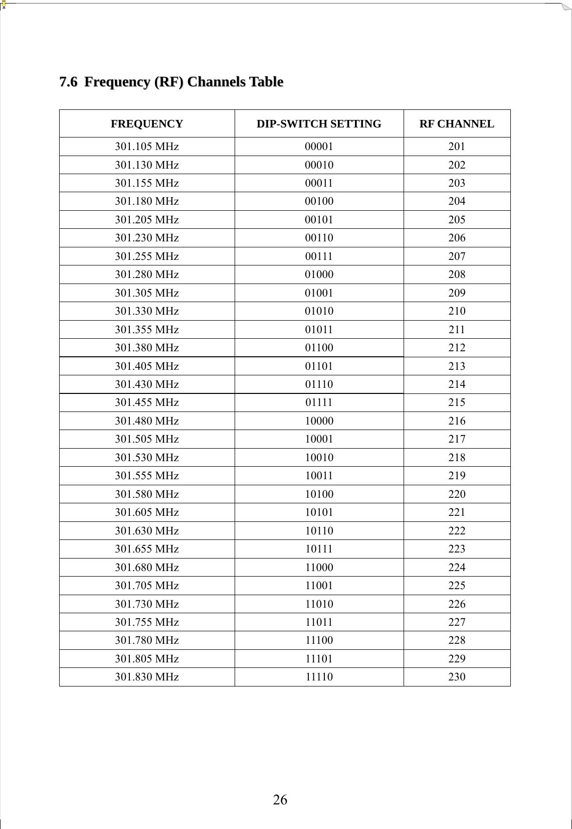
Fomotech ALPHA580SERIES Industrial Remote Control User Manual TITAN RV4 2 ODD M1 301MHZ GR
Fomotech International Corp. Industrial Remote Control TITAN RV4 2 ODD M1 301MHZ GR
UserManual.wiki
>
Fomotech
>
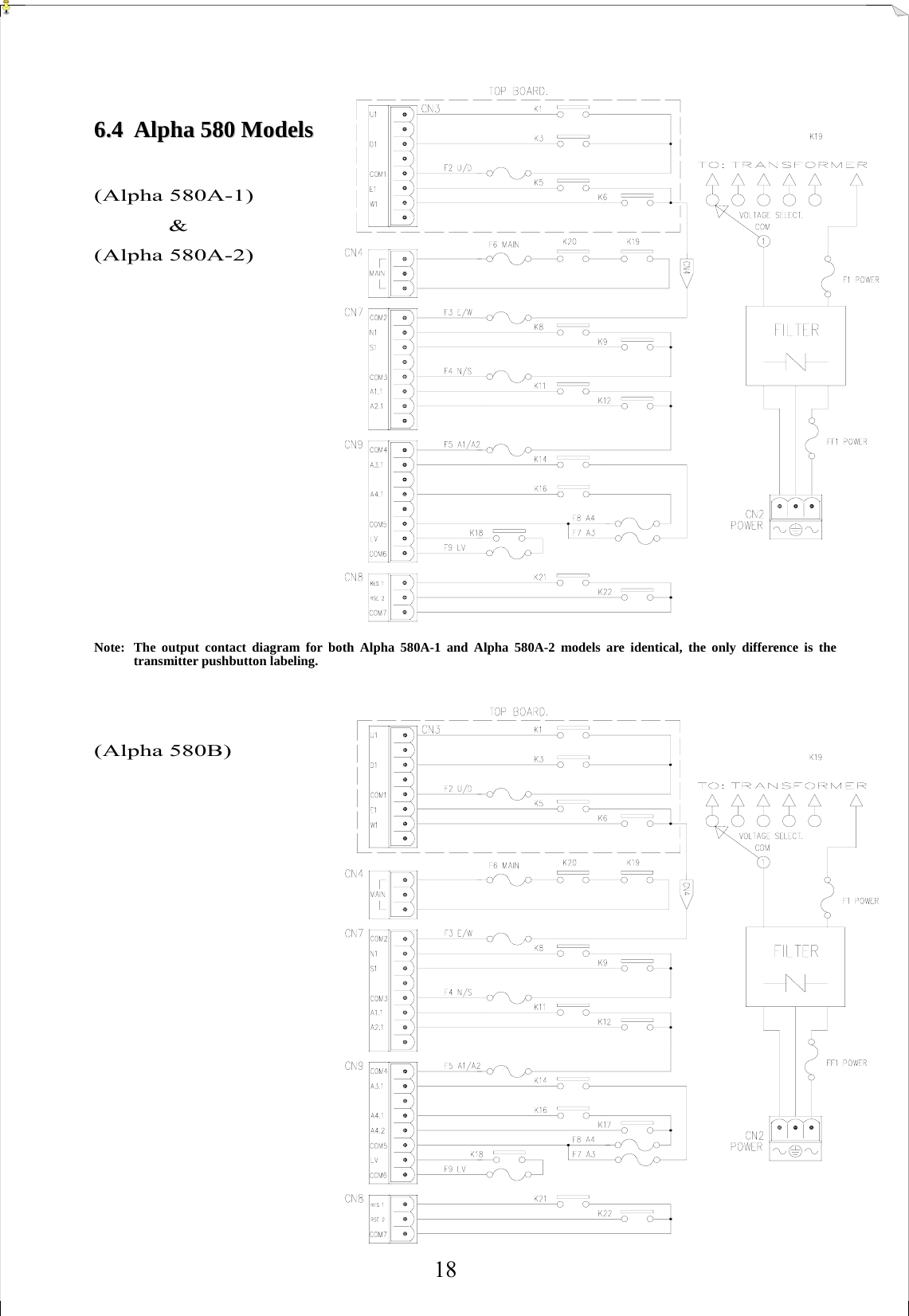
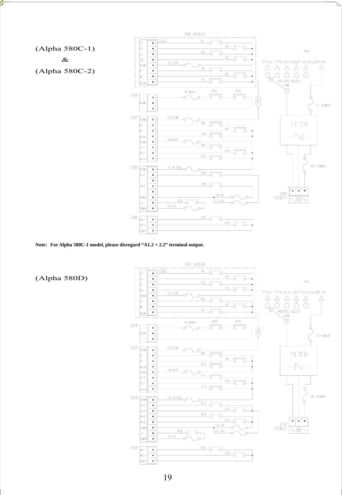
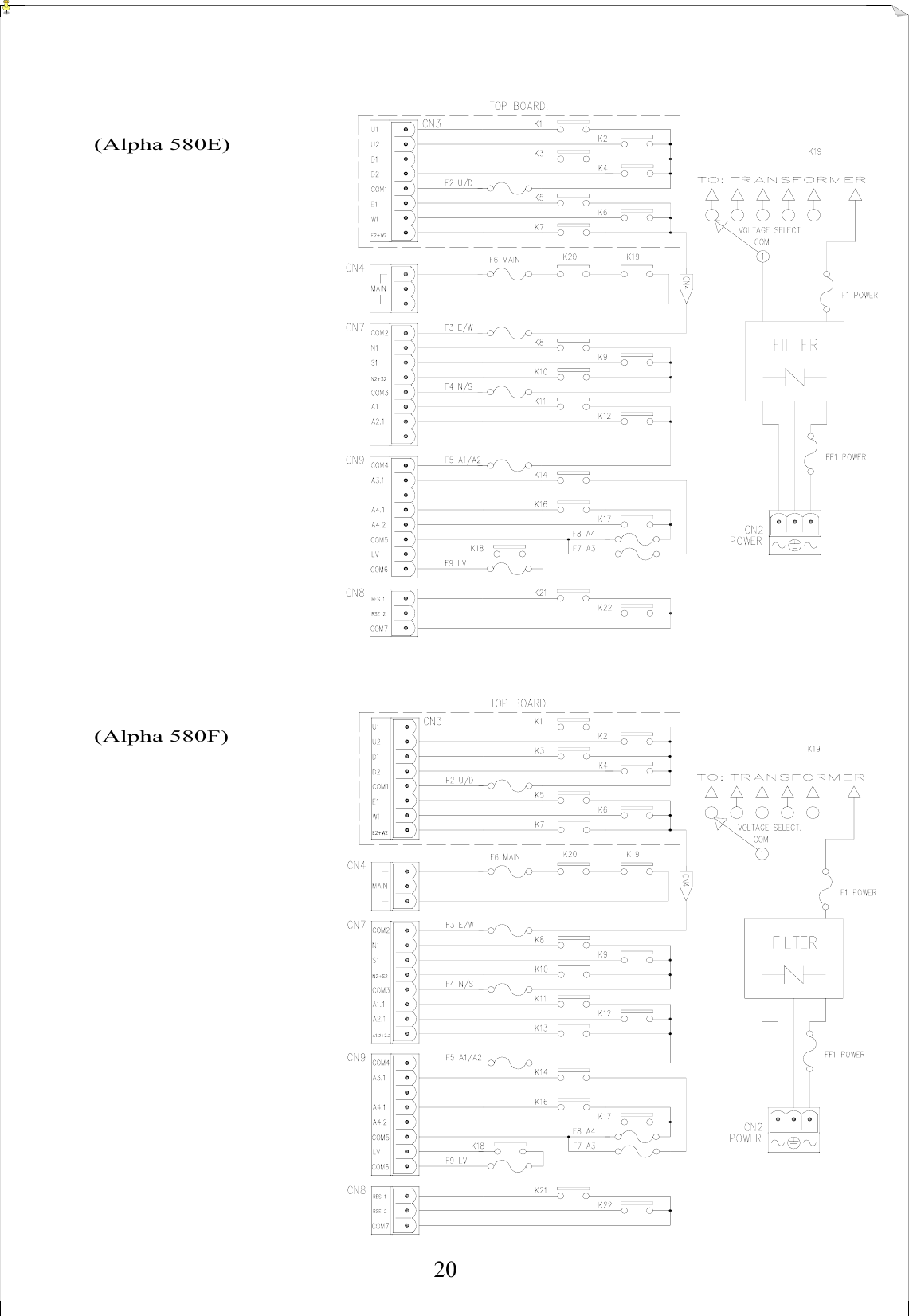
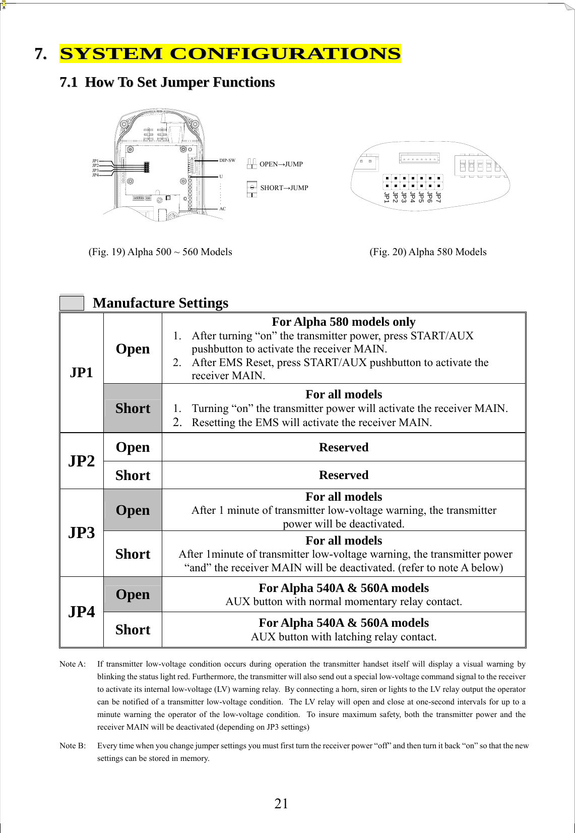
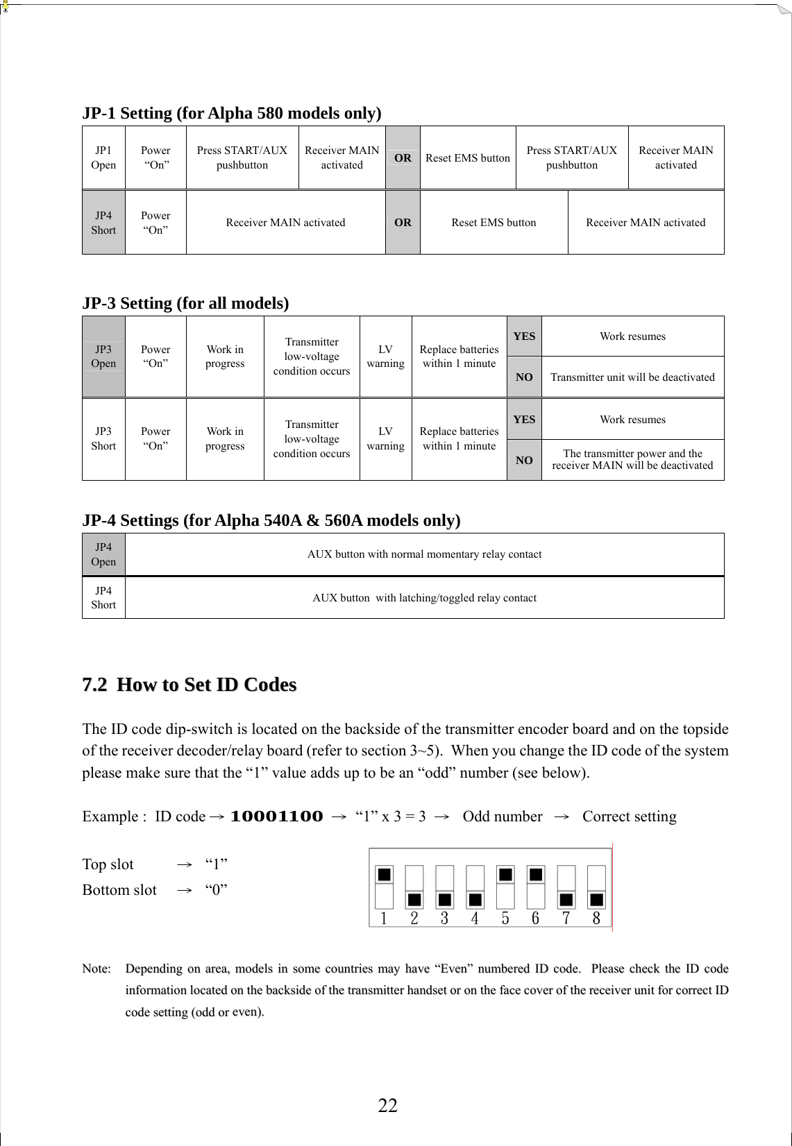
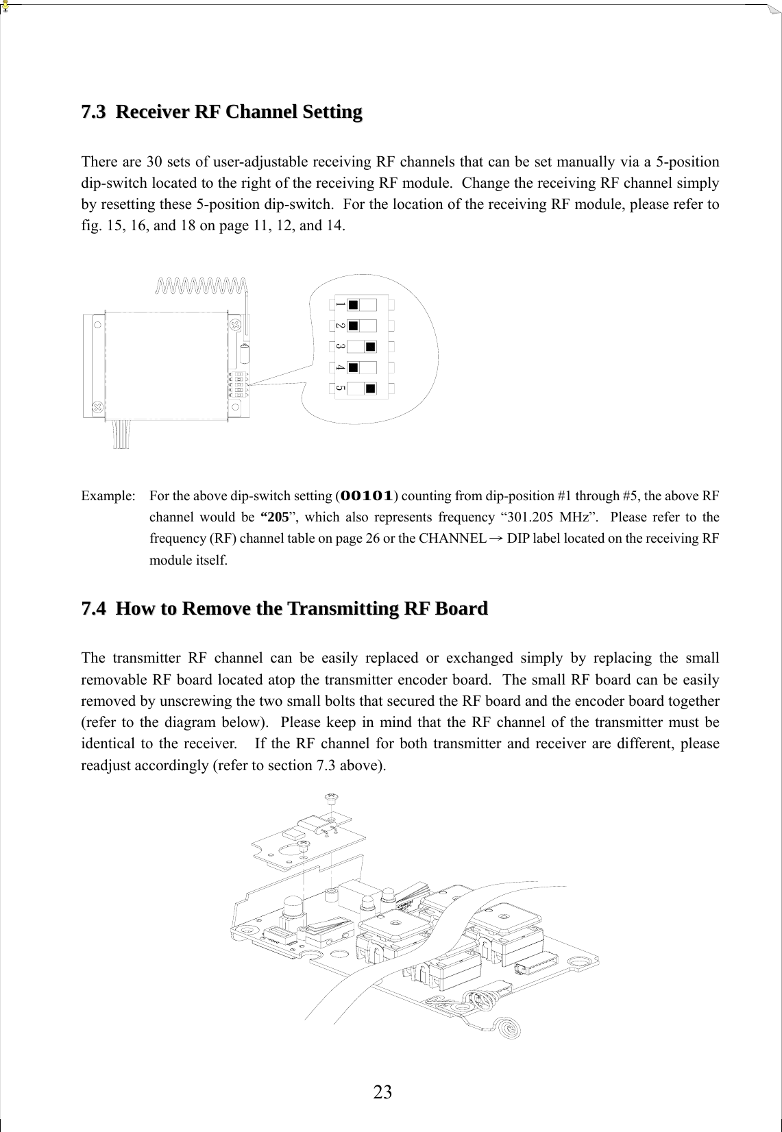
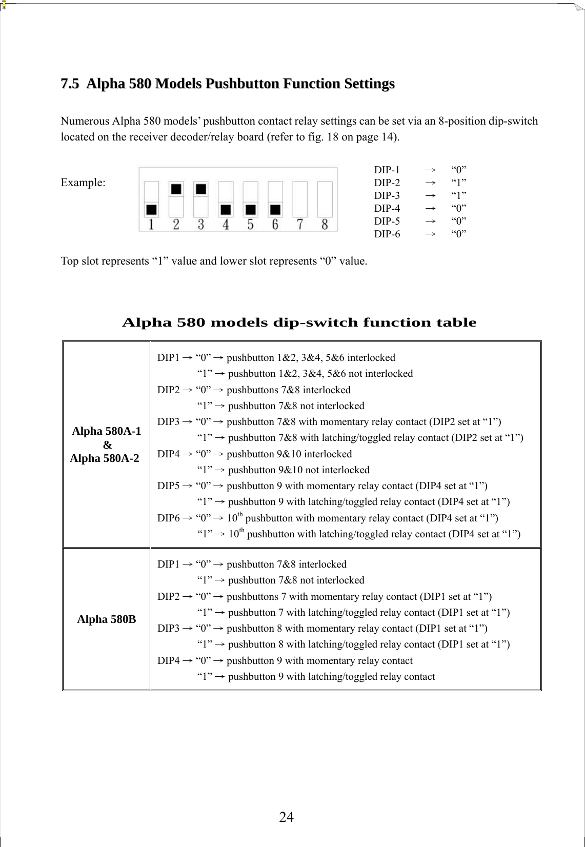
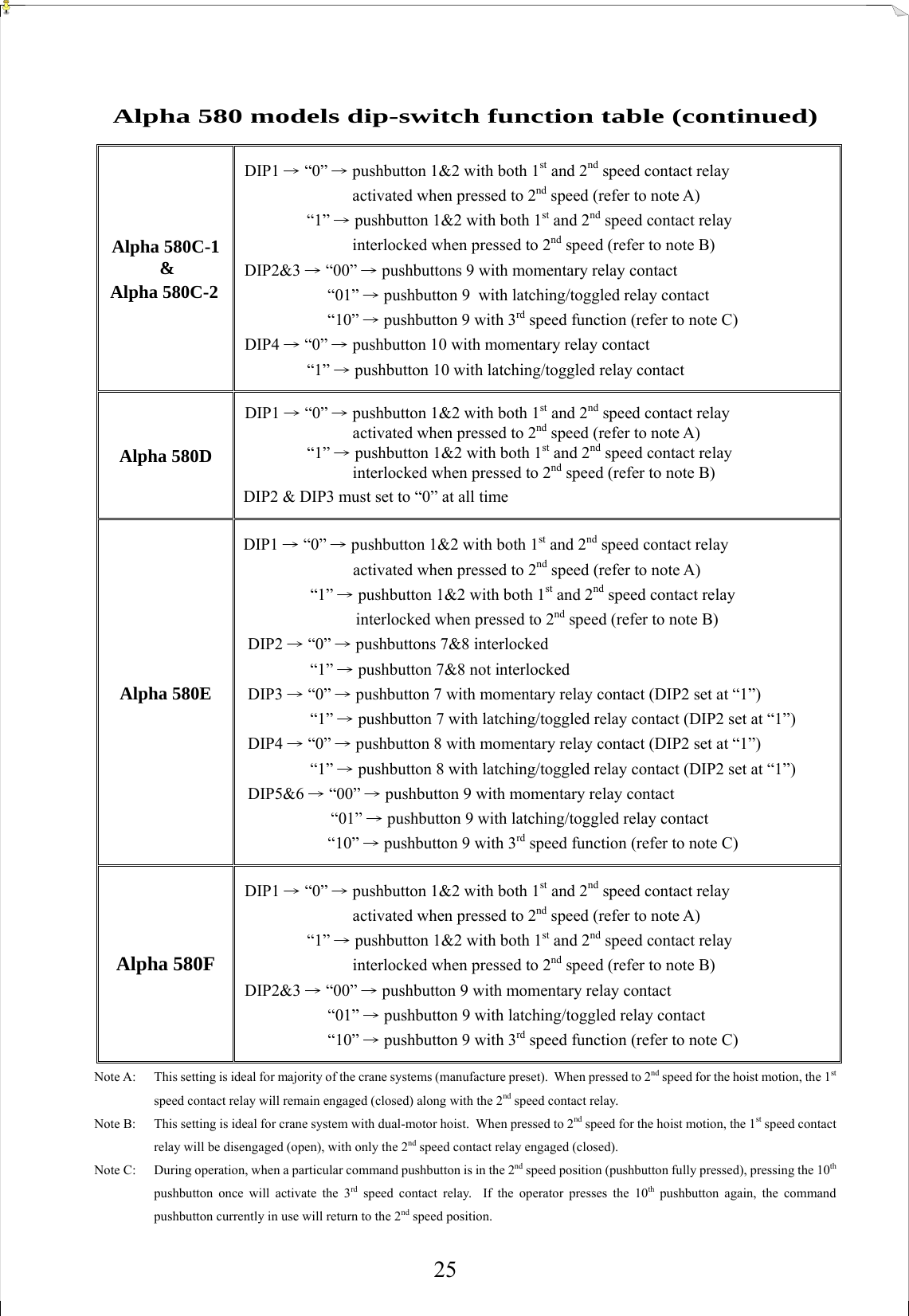
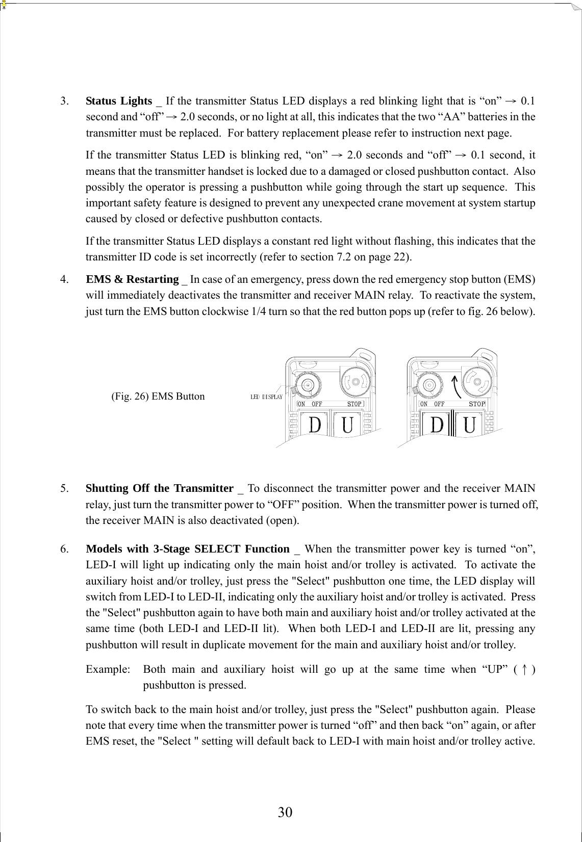
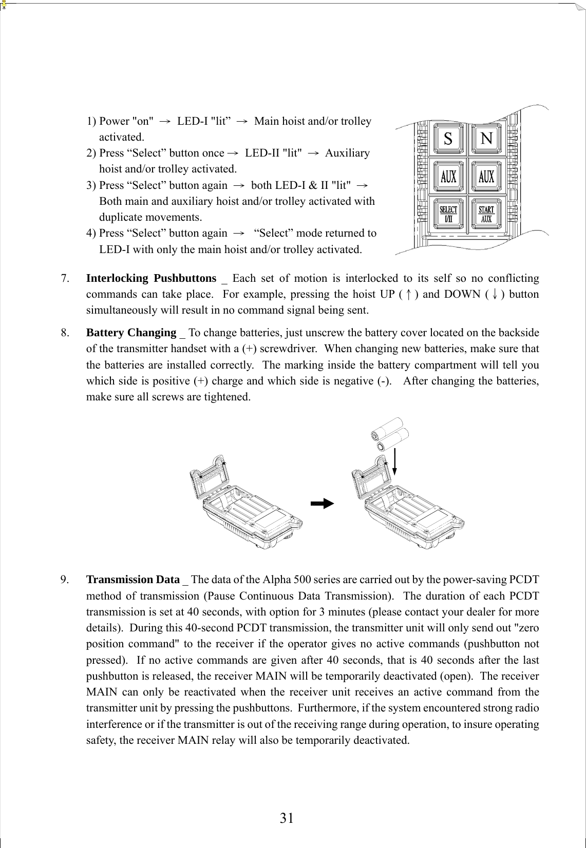
ALPHA580SERIES User Manual
User Manual
Navigation menu
Upload a User Manual
Namespaces
Wiki Guide
HTML
PDF
Info
Views
User Manual
Discussion / Help
Navigation