Fomotech ALPHA580SERIES Industrial Remote Control User Manual TITAN RV4 2 ODD M1 301MHZ GR
Fomotech International Corp. Industrial Remote Control TITAN RV4 2 ODD M1 301MHZ GR
Fomotech >
User Manual

1
T
TA
AB
BL
LE
E
O
OF
F
C
CO
ON
NT
TE
EN
NT
TS
S
Page
1. INTRODUCTION ....................................................................................................... 2
2. SAFETY INSTRUCTION ............................................................................................. 3
3. PUSHBUTTON CONFIGURATION
3.1 Alpha 500 & 520 Models ..................................................................................... 4
3.2 Alpha 540 & 560 Models ..................................................................................... 5
3.3 Alpha 580 Models ............................................................................................... 6
4. TRANSMITTER OUTLINE
4.1 Alpha 500 & 520 Models ..................................................................................... 7
4.2 Alpha 540 & 560 Models ..................................................................................... 8
4.3 Alpha 580 Models ............................................................................................... 9
5. RECEIVER OUTLINE
5.1 Alpha 500 ~ 560 Models External Assembly ....................................................... 10
5.2 Alpha 500 & 520 Models Internal Assembly ....................................................... 11
5.3 Alpha 540 & 560 Models Internal Assembly ....................................................... 12
5.4 Alpha 580 Models External Assembly ................................................................. 13
5.5 Alpha 580 Models Internal Assembly ................................................................. 14
6. OUTPUT CONTACT DIAGRAMS
6.1 Alpha 500 & 520 Models ..................................................................................... 15
6.2 Alpha 540 Models ................................................................................................. 16
6.3 Alpha 560 Models ................................................................................................. 17
6.4 Alpha 580 Models ................................................................................................. 18~20
7. SYSTEM CONFIGURATIONS
7.1 How to Set Jumper Functions ............................................................................. 21~22
7.2 How to Set ID Codes ............................................................................................. 22
7.3 Receiver RF Channel Setting ............................................................................. 23
7.4 How to Remove the Transmitter RF Board ......................................................... 23
7.5 Alpha 580 Pushbutton Function Settings ............................................................. 24~25
7.6 Frequency (RF) Channel Table ............................................................................. 26
8. RECEIVER INSTALLATION
8.1 Preparation For Installation ................................................................................... 27
8.2 Step-By-Step Installation ....................................................................................... 27
8.3 System Testing ....................................................................................................... 28
9. TRANSMITTER OPERATION ................................................................................... 29~31
10. TROUBLE SHOOTING ............................................................................................... 32
11. SYSTEM SPECIFICATION ......................................................................................... 33
12. PARTS LIST ................................................................................................................. 34~35

2
1
1.
.
I
IN
NT
TR
RO
OD
DU
UC
CT
TI
IO
ON
N
The Alpha 500 series are highly durable, reliable and safe industrial radio remote control systems. The
versatile features of the Alpha 500 series permit their use in many different remote control applications.
The systems can be used to control factory cranes, monorail systems, multiple hoists, trolleys, mining
equipment, building construction equipment, automatic control systems, and many others.
The system incorporates numerous redundant safety circuits that guaranty maximum security and
ensure the system is resistant to outside interference. The major features of the Alpha 500 series are as
follow:
* The system uses advanced microprocessors with highly evolved software that has redundant
error checking and correcting capabilities to ensure 100% error-free transmission, decoding, and
control of all output relays. This highly evolved software includes CRC (Cyclical Redundancy
Check Code) and Hamming Codes (Error Recovery) programming.
* To insure maximum operating safety, the Alpha 500 series incorporates numerous important
safety features. Some of these built in safety features include transmitter pushbutton
self-diagnosing during initial startup, transmitter low-voltage detection and visual warning with
additional output for external warning light connection (LV relay), receiver self-diagnosing,
MAIN deactivation during transmitter low-voltage, when system is in sleep mode, when system
encountering strong RF interference, and when the transmitter is out of the receiving range.
* The transmitter encoder and receiver decoder both utilize advanced microprocessor control. The
availability of 32,768 sets of unique ID codes + 30 distinct RF channels will ensure that only
commands from the matching control transmitter can be carried out without any interference
from other radio systems.
* For added safety, the system also incorporates special type of safety MAIN contact relay or relays.
If the safety MAIN relay becomes defective (fails to open or close during operation or not
responding to a “stop” command), it will signal the system to shut down immediately to avoid the
possibility of any accidents occurring.
* 30 sets of user-adjustable receiving RF channels plus special designed removable transmitting
RF board for easy channel replacement and service maintenance.
* Waterproofed transmitter and receiver enclosures, including the battery compartment.
The Alpha 500 series radio remote control systems consist of water-resistant IP-66 transmitters and
IP-65 / IP-66 receivers. All receiver s are equipped with a 2-meter pre-wired output cable (Alpha 500
~ 560 models). The transmitter casings are molded using industrial strength composite materials
which are impervious to dust, water, oil, acids, alkaline, heat and sunlight as well as being resistant to
deformation due to long term use in harsh environments. The pushbuttons are also constructed from
industrial strength composite materials with minimum of up to one million press cycles. For battery
power savings, the transmitter is designed and manufactured with a special ultra-efficiency
power-saving circuit that requires only two “AA” size alkaline batteries for more than 150 hours of
continuous operation.

3
2
2.
.
S
SA
AF
FE
ET
TY
Y
I
IN
NS
ST
TR
RU
UC
CT
TI
IO
ON
N
The Alpha 500 series are relatively simple to use, however, it is very important to observe the proper
safety procedures before, during, and after operation. When used properly, the Alpha 500 series will
enhance safety, productivity and efficiency in the workplace.
The following procedures should be strictly followed:
1. Check the transmitter casing and pushbuttons daily. Should any damage that could inhibit the
proper operation of the transmitter be found the unit should be immediately removed from
service.
2. The transmitter voltage should be checked on a daily basis. If the voltage is low (red status light
blinking or completely off), the two “AA” alkaline batteries should be replaced.
3. The red emergency stop button (EMS) should be checked at the beginning of each shift to ensure
it is in proper working order and the “Stop” command is being received by the receiver.
4. In the event of an emergency press down the EMS button will immediately deactivates the
receiver MAIN relay and the transmitter power. Then turned the power “off” from the main
power source to the crane or equipment.
5. The transmitter power switch should be turned off after each use and should never be left in the
“power on” state when the unit is unattended.
6. Do not use the same RF channel and ID code as any other system in use at the same facility or
within 300-meter distance.
7. Ensure the wrist strap (Alpha 500 ~ 560 models) or the waist belt (Alpha 580 models) is worn at
all time during operation to avoid accidental damage to the transmitter.
8. Never operate a crane or equipment with two transmitters at the same time with the same RF
channel and ID code, as it will cause radio interference.
Caution!
Improper Storage of your Spare Transmitter is a Safety Hazard! During the initial installation
of your remote control system the spare (second) transmitter should be tested to confirm that it
is functioning properly and then the batteries must be removed and the transmitter stored in a
secured place. Failure to follow this safety procedure can result in the inadvertent operation of
your crane or hoist by unauthorized personnel resulting in serious injury or death!
15.21 ¡§Changes or modifications are not expressly approved by the manufacturer could void
the user's authority to operate the equipment.¡¨
"Operation is subject to the following two conditions: (1) this device may not cause interference,
and (2) this device must accept any interference, including interference that may cause undesired
operation of the device."
4
3
3.
.
P
PU
US
SH
HB
BU
UT
TT
TO
ON
N
C
CO
ON
NF
FI
IG
GU
UR
RA
AT
TI
IO
ON
N
3
3.
.1
1
A
Al
lp
ph
ha
a
5
50
00
0
&
&
5
52
20
0
M
Mo
od
de
el
ls
s
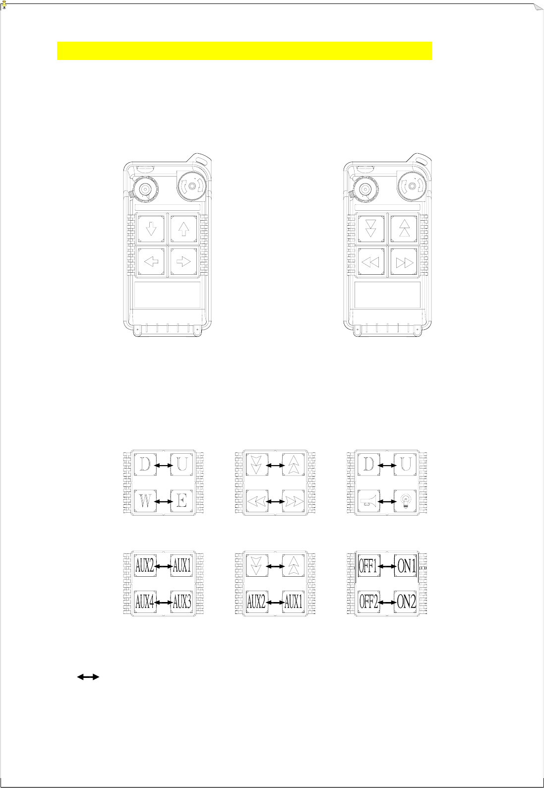
1. Alpha 500 : (4) one-speed pushbuttons.
2. Alpha 520 : (4) two-speed pushbuttons.
(Alpha 500) (Alpha 520)
Below are some of many types of pushbutton configurations that are also available, please
contact your dealer for more details.
Interlocked (Can also be set to non-interlocked via an external programmer unit).
ON OFF STOP STOP
ON OFF
5
3
3.
.2
2
A
Al
lp
ph
ha
a
5
54
40
0
&
&
5
56
60
0
M
Mo
od
de
el
ls
s
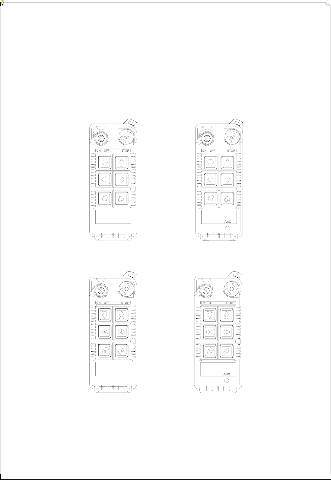
1. Alpha 540S : (6) one-speed pushbuttons.
2. Alpha 540A : (6) one-speed pushbuttons + (1) AUX micro-button.
3. Alpha 560S : (6) two-speed pushbuttons.
4. Alpha 560A : (6) two-speed pushbuttons + (1) AUX micro-button.
(Alpha 540S) (Alpha 540A)
(Alpha 560S) (Alpha 560A)
6
3
3.
.3
3
A
Al
lp
ph
ha
a
5
58
80
0
M
Mo
od
de
el
ls
s
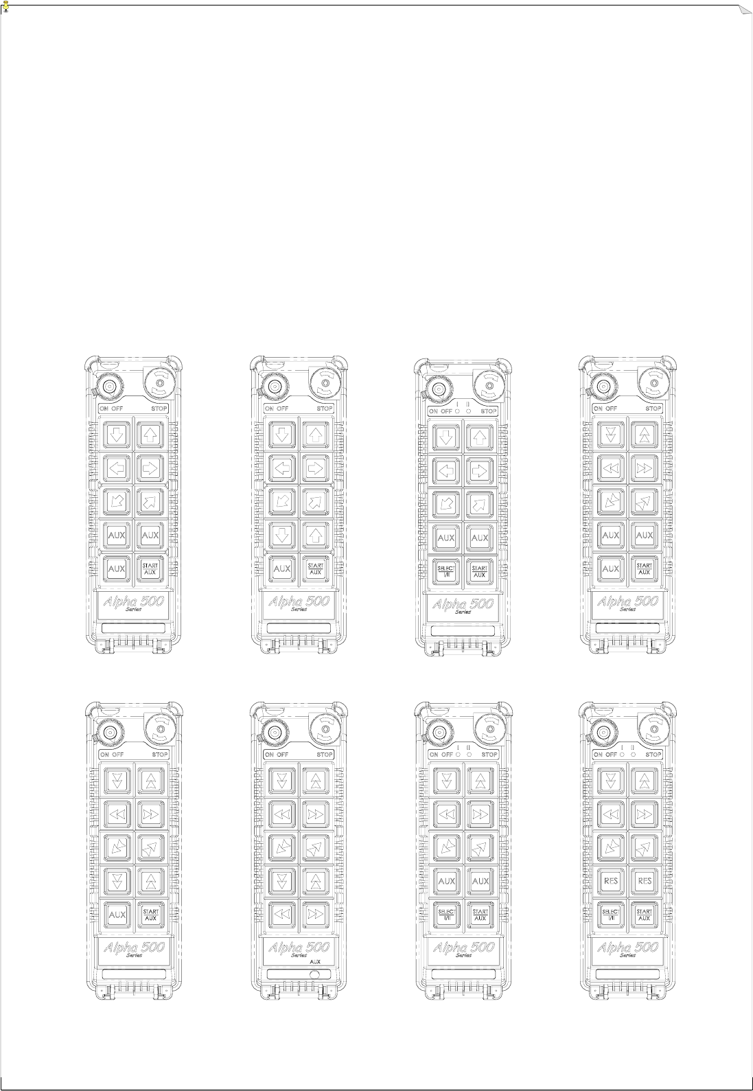
1. Alpha 580A-1 : (10) one-speed pushbuttons (labeled as 3 motions).
2. Alpha 580A-2 : (10) one-speed pushbuttons (labeled as 4 motions).
3. Alpha 580B : (9) one-speed pushbuttons + (1) SELECT I/II pushbutton.*
4. Alpha 580C-1 : (6) two-speed + (4) one-speed pushbuttons.
5. Alpha 580C-2 : (8) two-speed + (2) one-speed pushbuttons.
6. Alpha 580D : (10) two-speed pushbuttons + (1) AUX micro-button.
7. Alpha 580E : (6) two-speed + (3) one-speed pushbuttons + (1) SELECT I/II pushbutton.*
8. Alpha 580F : (8) two-speed + (1) one-speed pushbutton + (1) SELECT I/II pushbutton.*
* For cranes with auxiliary hoist and trolley (changeover function).
(Alpha 580A-1) (Alpha 580A-2) (Alpha 580B) (Alpha 580C-1)
(Alpha 580C-2) (Alpha 580D) (Alpha 580E) (Alpha 580F)
7
14
15
16
On
12347
568
17
4
4.
.
T
TR
RA
AN
NS
SM
MI
IT
TT
TE
ER
R
O
OU
UT
TL
LI
IN
NE
E
4
4.
.1
1
A
Al
lp
ph
ha
a
5
50
00
0
&
&
5
52
20
0
M
Mo
od
de
el
ls
s
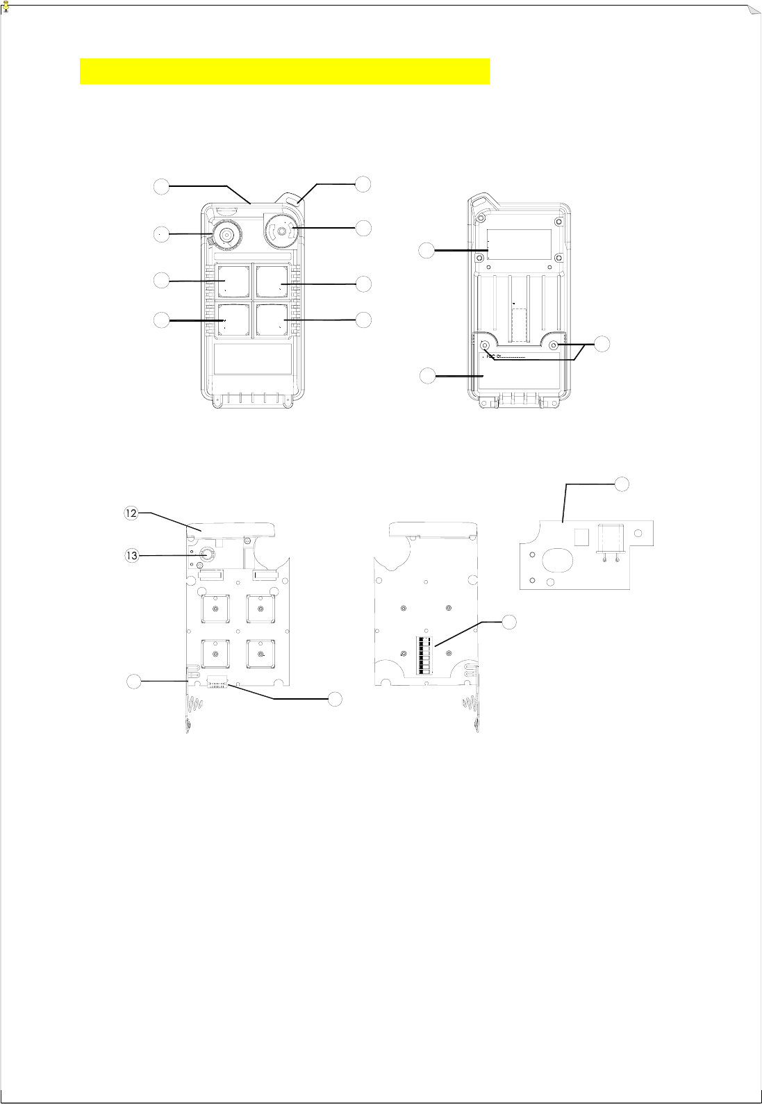
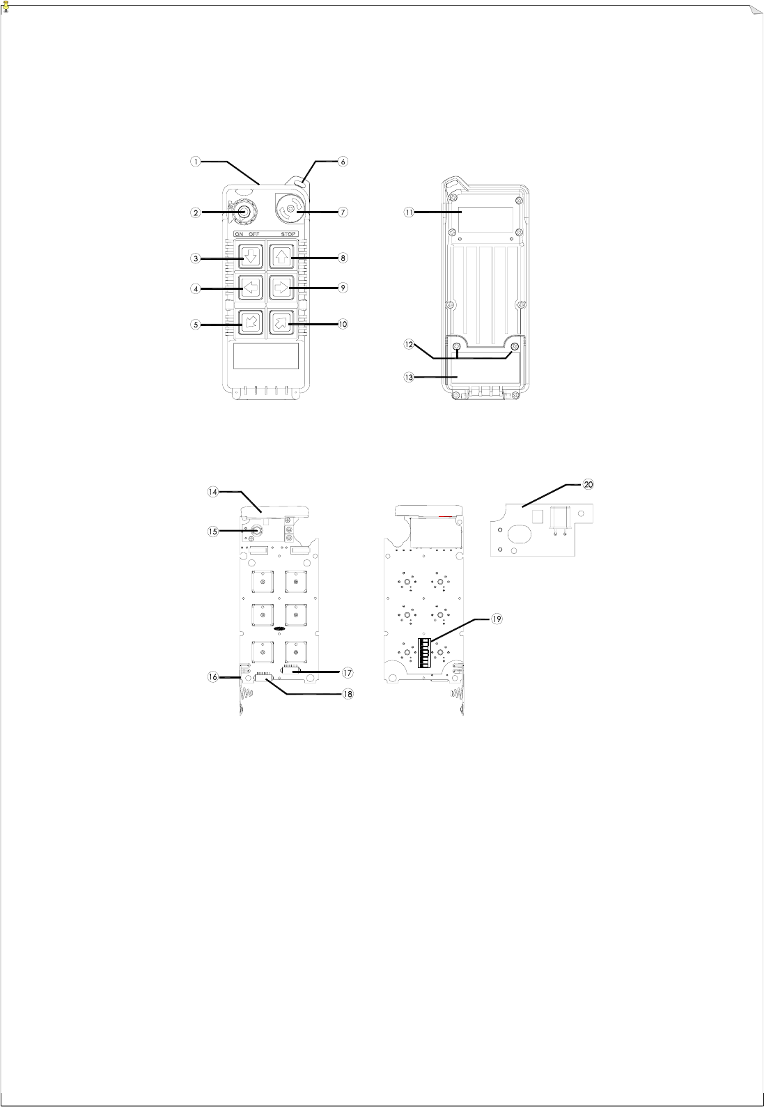
(Fig. 1) Front View (Fig. 2) Back View
(Fig. 3) Front View (Fig. 4) Back View
1) Transmitter enclosure 8) Pushbutton # 3 (→ / East) 15) Programming port
2) Power switch (ON/OFF) 9) System information 16) ID code dip-switch
3) Pushbutton #2 (↓ / Down ) 10) Battery cover 17) Transmitting RF Board
4) Pushbutton #4 (← / West) 11) Battery cover screws
5) Wrist strap attachment 12) Internal antenna
6) Emergency stop (EMS) 13) Status LED display
7) Pushbutton #1 (↑ / Up) 14) Battery contact
1
2
3
4
5
6
7
8
9
10
11
ON OFF STOP
8
On
12347
568
4
4.
.2
2
A
Al
lp
ph
ha
a
5
54
40
0
&
&
5
56
60
0
M
Mo
od
de
el
ls
s
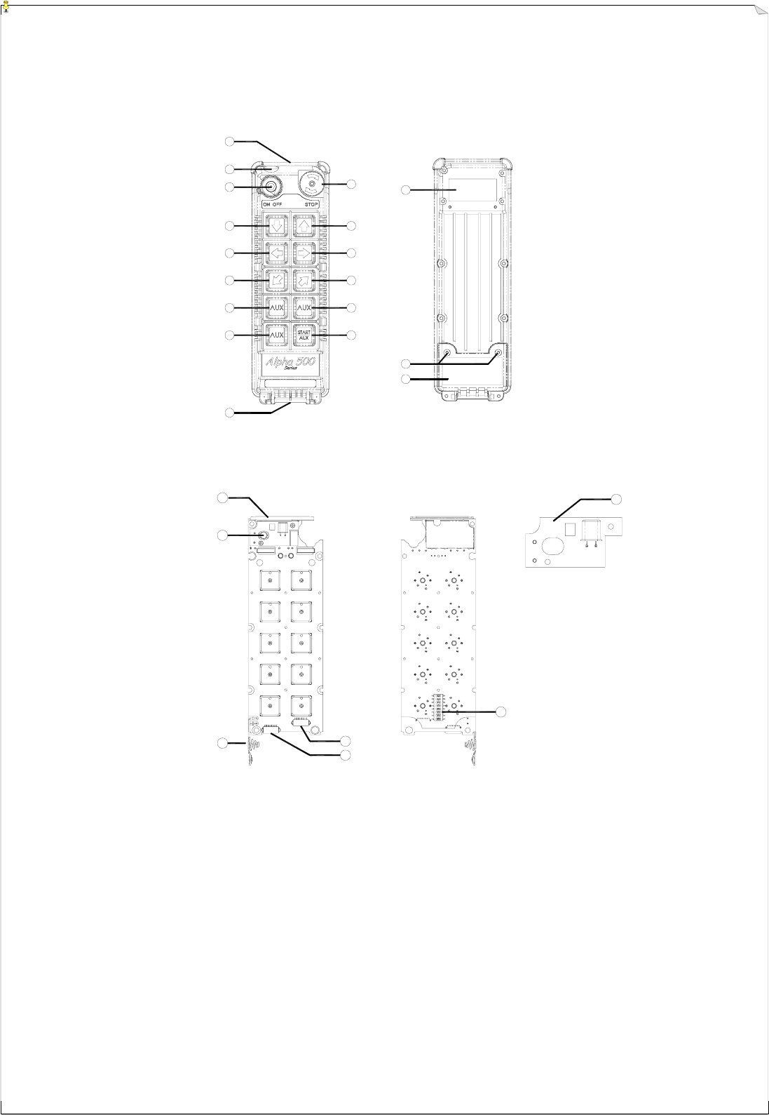
(Fig. 5) Front View (Fig. 6) Back View
(Fig.7) Front View (Fig. 8) Back View
1) Transmitter enclosure 8) Pushbutton #1 (↑ / Up) 15) Status LED display
2) Power switch (ON/OFF) 9) Pushbutton #3 (→ / East) 16) Battery contact
3) Pushbutton #2 (↓ / Down) 10) Pushbutton #5 (↗ / North) 17) AUX micro-button connector*
4) Pushbutton #4 (← / West) 11) System information 18) Programming port
5) Pushbutton #6 (↙ / South) 12) Battery cover screws 19) ID code dip-switch
6) Wrist strap attachment 13) Battery cover 20) Transmitting RF board
7) Emergency stop (EMS) 14) Internal antenna
* For Alpha 540A and Alpha 560A models only.
9
1
2
3
4
5
6
7
8
10
17
18
16
9
11
12
13
14
15
20
21 22
23
24
25
19
4
4.
.3
3
A
Al
lp
ph
ha
a
5
58
80
0
M
Mo
od
de
el
ls
s
(Fig. 9) Front View (Fig. 10) Back View
(Fig. 11) Front View (Fig. 12) Back View
1) Transmitter enclosure 9) Waist belt attachment 17) Battery cover screws
2) External antenna port 10) Emergency stop (EMS) 18) Battery cover
3) Power switch (ON/OFF) 11) Pushbutton #1 (↑ / Up) 19) Internal antenna
4) Pushbutton #2 (↓ / Down) 12) Pushbutton #3 (→ / East) 20) Status LED display
5) Pushbutton #4 (← / West) 13) Pushbutton #5 (↗ / North) 21) Battery contact
6) Pushbutton #6 (↙ / South) 14) Pushbutton #7 (A1) 22) AUX micro-button connector*
7) Pushbutton #8 (A2) 15) Pushbutton #9 (A3) 23) Programming port
8) Pushbutton #10 (A4) 16) System information 24) ID code dip-switch
25) Transmitting RF board
* For optional AUX micro-button or buttons.
10
5
5.
.
R
RE
EC
CE
EI
IV
VE
ER
R
O
OU
UT
TL
LI
IN
NE
E
5
5.
.1
1
A
Al
lp
ph
ha
a
5
50
00
0
~
~
5
56
60
0
M
Mo
od
de
el
ls
s
E
Ex
xt
te
er
rn
na
al
l
A
As
ss
se
em
mb
bl
ly
y
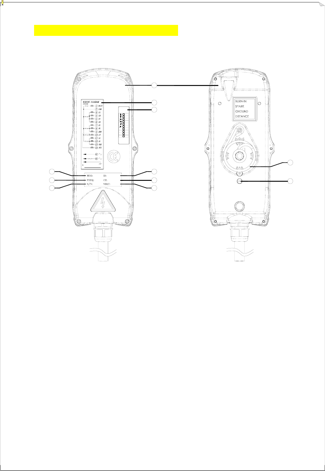
(Fig. 13) Front View (Fig. 14) Back View
1) Receiver enclosure 5) System frequency 9) Supplied voltage
2) Wiring diagram 6) System serial number 10) Anti-vibration spring
3) Receiver LED displays* 7) System ID code 11) Grounding (GND)
4) Type model 8) System RF channel
* A ~ AUX Relay Contact Indicator (for Alpha 540A/560A models only).
* M ~ MAIN and 2nd Speed Relay Contact Indicator.
Green "on" → MAIN activated (All models).
Red "on" → 2nd speed activated (for Alpha 560S/A models only).
* SQ ~ RF Signal Indicator (Red).
"on" → RF signal detected and received.
"off" → No RF signal detected or received.
Blinking at transmitter power "off" → Other radio interference.
* AC ~ Power Source Indicator (red) "on" → AC input power supplied.
"off" → No AC input power.
1A
POWER
AC220V 50/60HZ
must be grounded
Anti-vibration s pring
5A
N/S
5A
5A
5A
LV,AUX
E/W
MAIN
U/D
5A
AC
SQ
M
A
W
S
N
E
U
D
AC
SQ
M
A
4
5
6
7
9
8
2
3
1
10
11
11
1
2
3
4
5
5.
.2
2
A
Al
lp
ph
ha
a
5
50
00
0
&
&
5
52
20
0
M
Mo
od
de
el
ls
s
I
In
nt
te
er
rn
na
al
l
A
As
ss
se
em
mb
bl
ly
y
(Fig. 15) Internal Parts Assembly
1) Receiving RF module
2) Secondary power AC fuse (0.50A)
3) Primary power AC fuse (1.0A)
4) System status LED display*
5) External antenna port
6) ID code dip-switch
7) RF channel dip-switch
8) Contact relay LED display
9) Pushbutton #1 and #2 fuse (5.0A)
10) MAIN fuse (5.0A)
11) Contact output seat (CN3)
12) Low-voltage (LV) fuse (5.0A)
13) Contact output seat (CN4)
14) Pushbutton #3 and #4 fuse (5.0A)
15) AC power input seat (CN2)
16) Cable gland & output cable
* Please refer to page 32 for system status
LED display information.
1) Spare fuse & jumper compartment
2) Spare Jumper slots
3) Spare fuse slots
4) Receiver top casing
3
7
6
8
9
10
11
12
14
15
5
13
16
FUSE
FUSE
FUSE
FUSE
FUSE
1
2
4
12
1
2
3
4
5
5.
.3
3
A
Al
lp
ph
ha
a
5
54
40
0
&
&
5
56
60
0
M
Mo
od
de
el
ls
s
I
In
nt
te
er
rn
na
al
l
A
As
ss
se
em
mb
bl
ly
y
(Fig. 16) Internal Parts Assembly
1) Receiving RF module
2) External programming port
3) Secondary power AC fuse (0.50A)
4) Contact output seat (CN8)
5) Primary power AC fuse (1.0A)
6) AC power input seat (CN2)
7) Internal Antenna
8) System Status LED display*
9) External antenna port
10) ID code dip-switch
11) RF channel dip-switch
12) Contact relay LED display
13) Pushbutton #1and #2 fuse (5.0A)
14) Contact output seat (CN3)
15) MAIN contact fuse (5.0A)
16) Pushbutton #3 and #4 fuse (5.0A)
17) Pushbutton #5 and #6 fuse (5.0A)
18) Contact output seat (CN4)
19) LV & AUX fuse (5.0A)
20) Cable gland & output cable
* Please refer to page 32 for system status
LED display information.
1) Spare fuse & jumper compartment
2) Spare Jumper slots
3) Spare fuse slots
4) Receiver top casing
3
5
6
7
19
4
11
10
12
13
14
15
17
18
9
16
20
FUSE
FUSE
FUSE
FUSE
FUSE
FUSE
1
2
8
13
1
2
3
4
5
5.
.4
4
A
Al
lp
ph
ha
a
5
58
80
0
M
Mo
od
de
el
ls
s
E
Ex
xt
te
er
rn
na
al
l
A
As
ss
se
em
mb
bl
ly
y
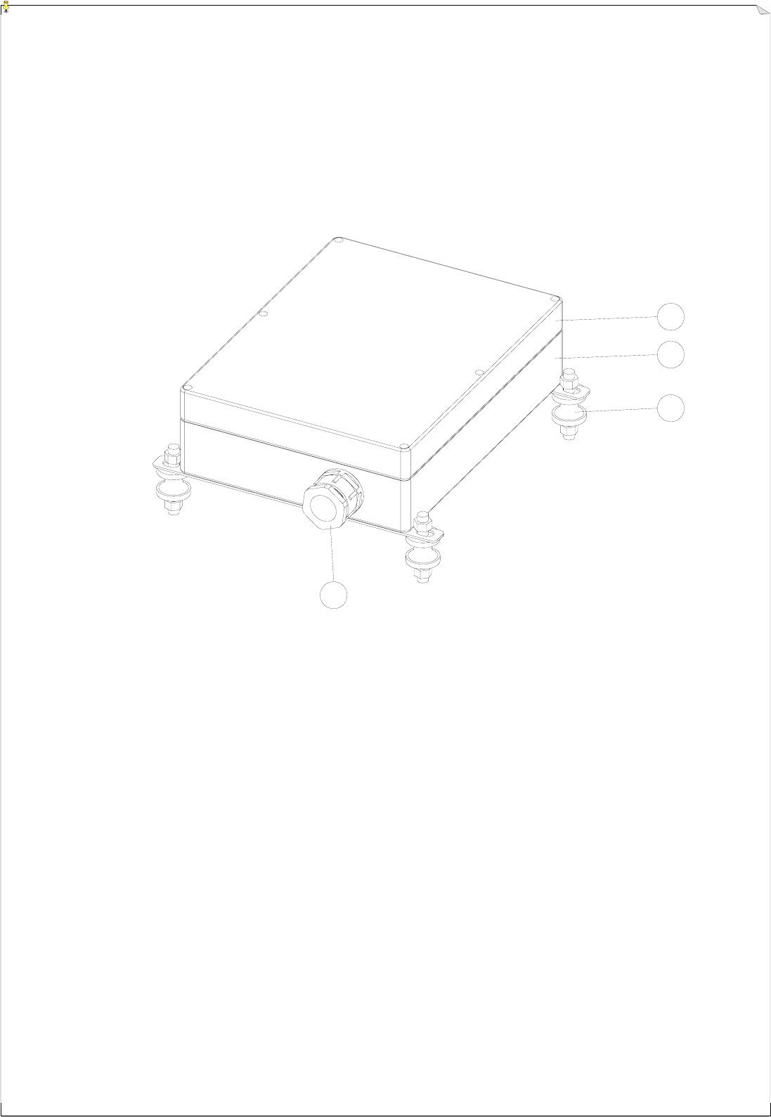
(Fig. 17) External Parts Assembly
1) Transparent top cover 3) Mounting bracket with shock absorbers
2) Light-gray colored base 4) Cable gland / Cord grip
14
17
20
19
18
16
14
5
10
11
9
7
8
6
1
3
4
213
15
12
5
5.
.5
5
A
Al
lp
ph
ha
a
5
58
80
0
M
Mo
od
de
el
ls
s
I
In
nt
te
er
rn
na
al
l
A
As
ss
se
em
mb
bl
ly
y
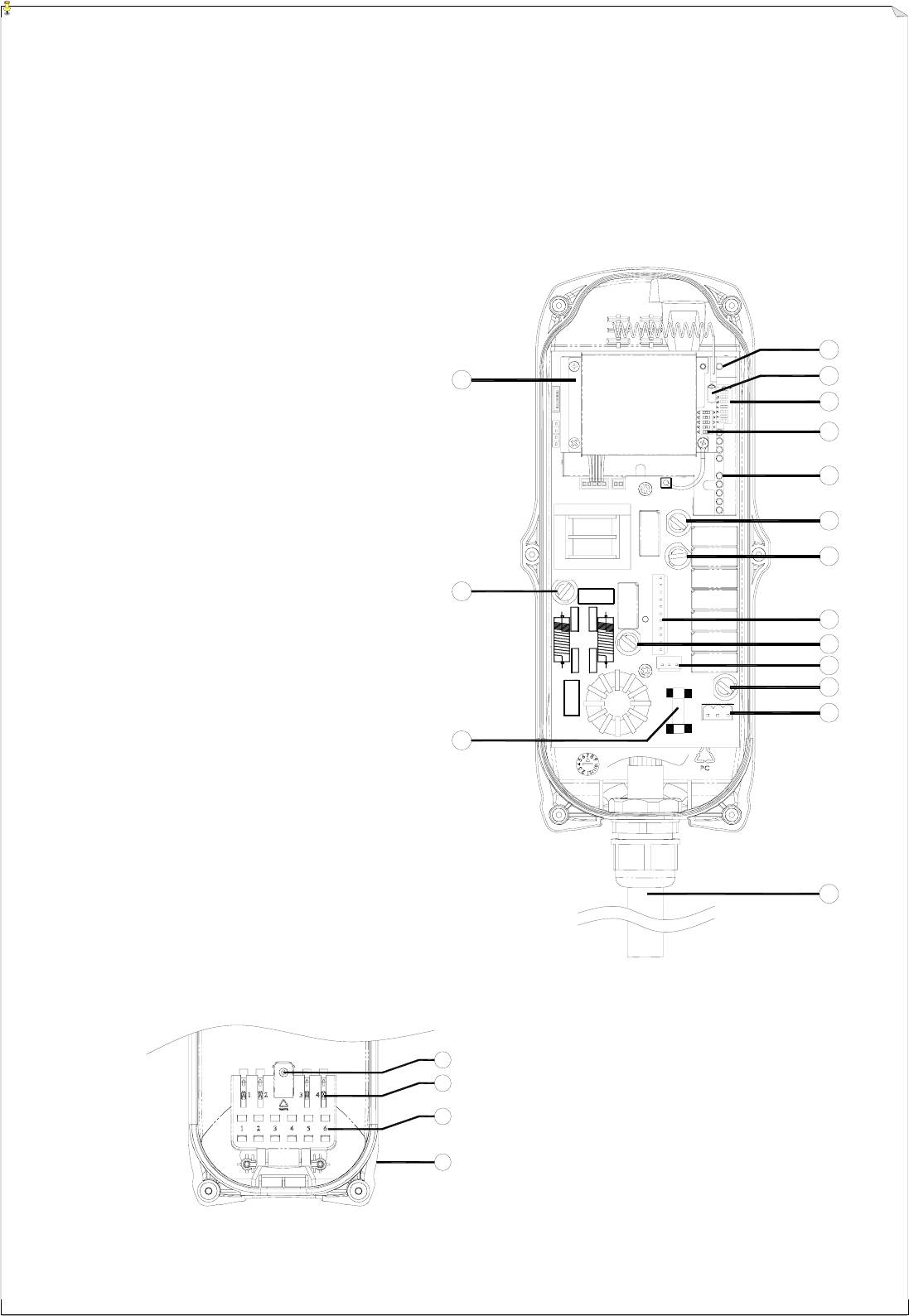
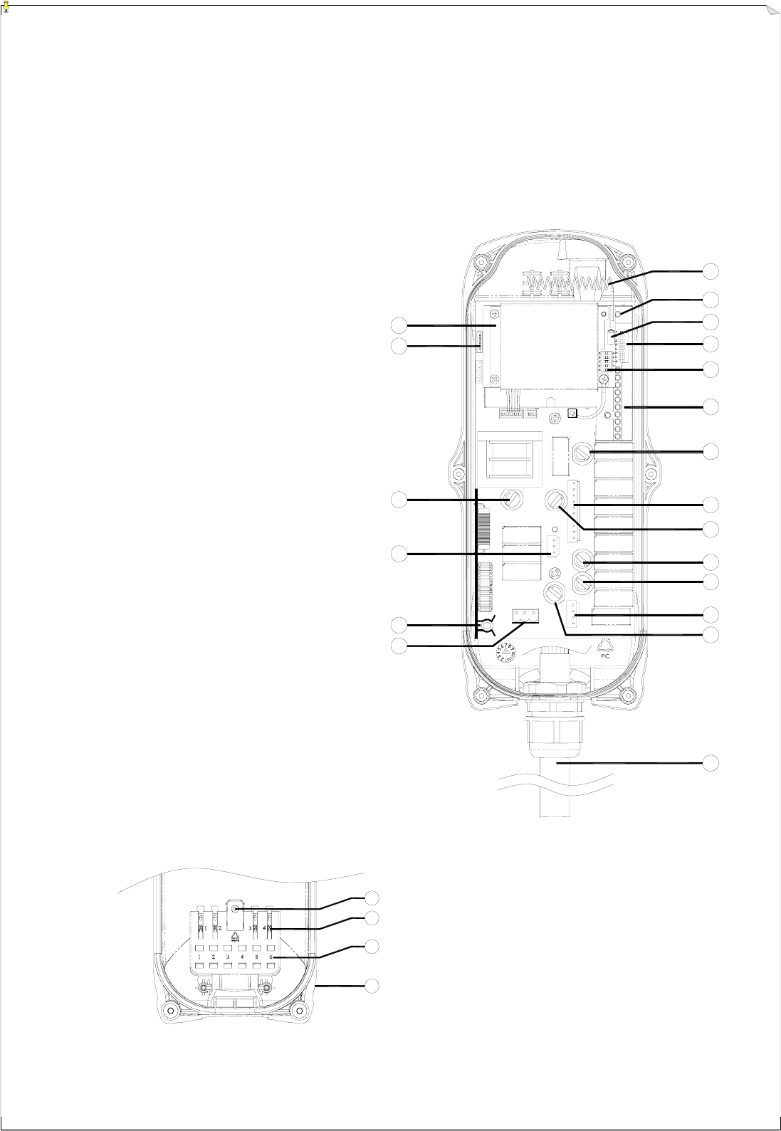
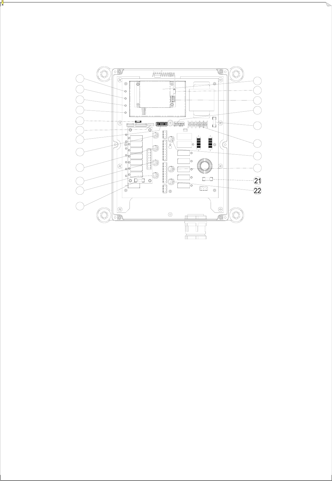
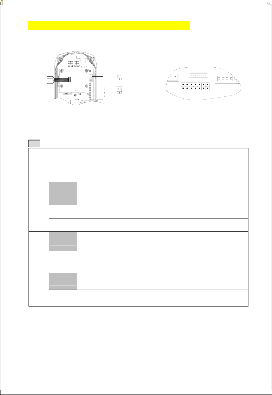
(Fig. 18) Internal Parts Assembly
1) Power LED display* 12) Pushbutton #1 and #2 relay fuse (5.0A)
2) SQ LED display** 13) Receiving RF module
3) Status LED display**** 14) External antenna port
4) DC power relay LED display*** 15) RF channel dip-switch
5) Programming port 16) ID code dip-switch
6) Jumper settings 17) Secondary power fuse (0.8A)
7) Function dip-switch 18) Voltage selector seat
8) Pushbutton #3 and #4 relay fuse (5.0A) 19) MAIN relay fuse (5.0A)
9) Pushbutton #5 and #6 relay fuse (5.0A) 20) Pushbutton A4 relay fuse (5.0A)
10) Pushbutton A1and A2 relay fuse (5.0A) 21) Primary power fuse (1.0A)
11) Pushbutton A3 relay fuse (5.0A) 22) Low-voltage (LV) relay fuse (5.0A)
* POWER ~ AC Power Source Indicator "on" → AC input power supplied.
"off" → No AC input power.
** SQ ~ RF Signal Indicator "on" → RF signal detected and received.
"off" → No RF signal detected or received.
Blinking at transmitter power “off” → Other radio interference.
*** RELAY_COM ~ DC Power Source to Relays "on" → DC power to relays.
"off" → No DC power to relays.
**** STATUS ~ Receiver System Status LED Display → Please refer to page 32.
15
6
6.
.
O
OU
UT
TP
PU
UT
T
C
CO
ON
NT
TA
AC
CT
T
D
DI
IA
AG
GR
RA
AM
MS
S
6
6.
.1
1
A
Al
lp
ph
ha
a
5
50
00
0
&
&
5
52
20
0
M
Mo
od
de
el
ls
s
(Alpha 500) (Alpha 520)
POWER
LV
5A
E/W
5A
U/D
5A
MAIN
5A
POWER
LV
5A
E/W
5A
U/D
5A
MAIN
5A
16
6
6.
.2
2
A
Al
lp
ph
ha
a
5
54
40
0
M
Mo
od
de
el
ls
s
(Alpha 540S) (Alpha 540A)
POWER
5A
5A
LV,AUX
E/W
MAIN
U/D
5A
5A
N/S
POWER
5A
5A
LV,AUX
E/W
MAIN
U/D
5A
5A
N/S
17
6
6.
.3
3
A
Al
lp
ph
ha
a
5
56
60
0
M
Mo
od
de
el
ls
s
(Alpha 560S) (Alpha 560A)
POWER
5A
5A
LV,AUX
E/W
MAIN
U/D
5A
5A
N/S
POWER
5A
5A
LV,AUX
E/W
MAIN
U/D
5A
5A
N/S
18
6
6.
.4
4
A
Al
lp
ph
ha
a
5
58
80
0
M
Mo
od
de
el
ls
s
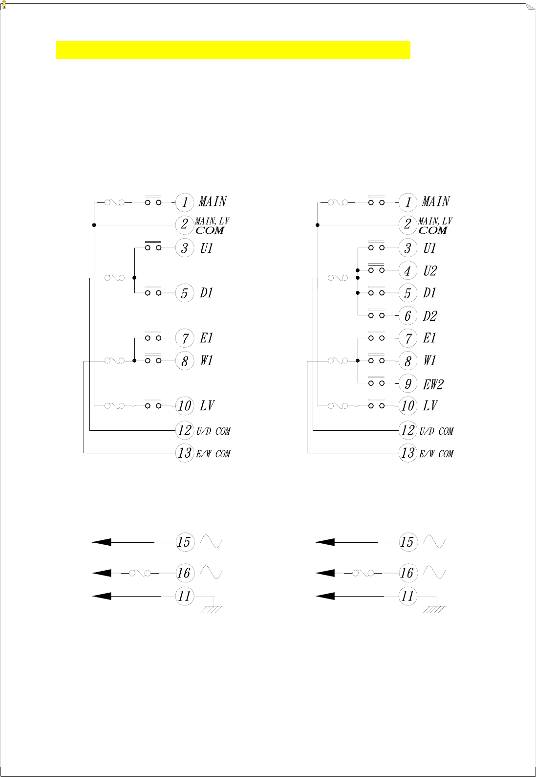
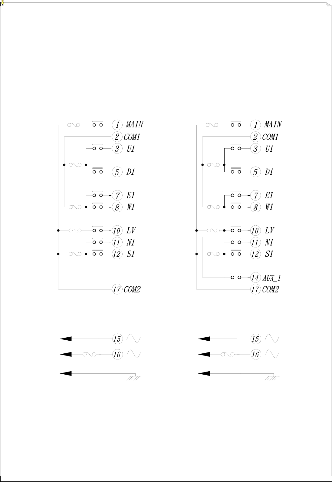
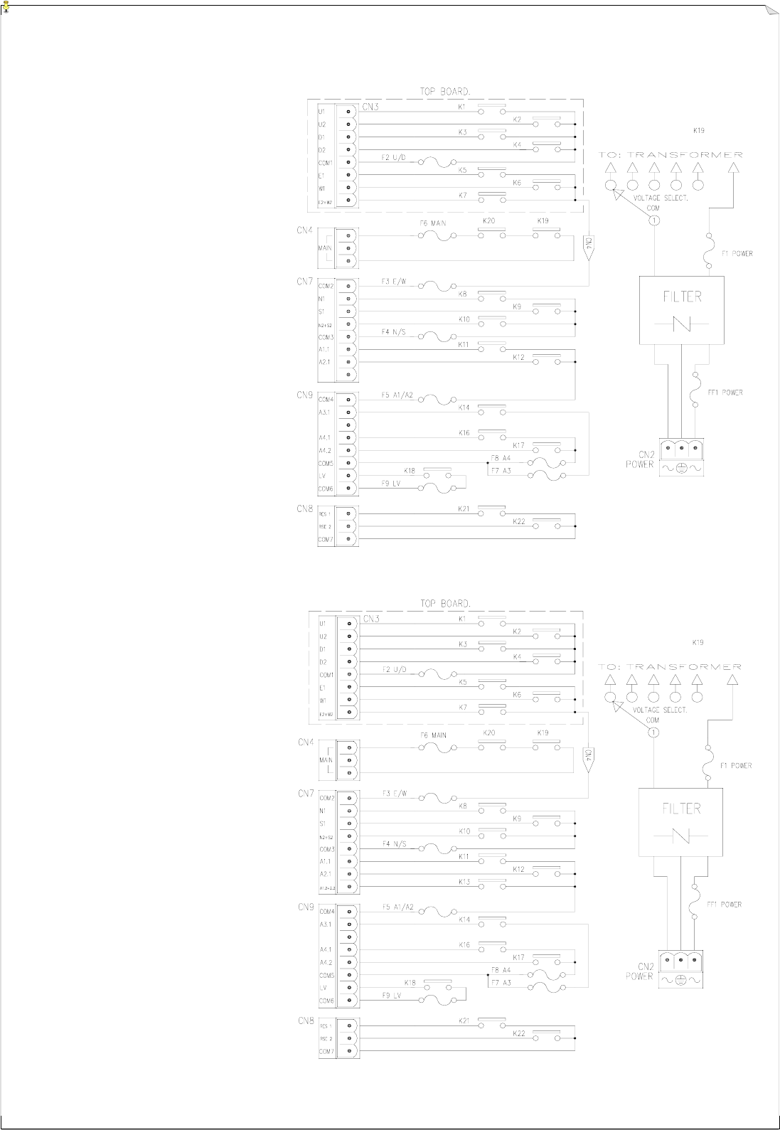
(Alpha 580A-1)
&
(Alpha 580A-2)
Note: The output contact diagram for both Alpha 580A-1 and Alpha 580A-2 models are identical, the only difference is the
transmitter pushbutton labeling.
(Alpha 580B)
19
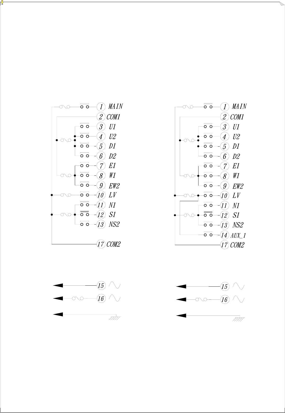
(Alpha 580C-1)
&
(Alpha 580C-2)
Note: For Alpha 580C-1 model, please disregard “A1.2 + 2.2” terminal output.
(Alpha 580D)
20
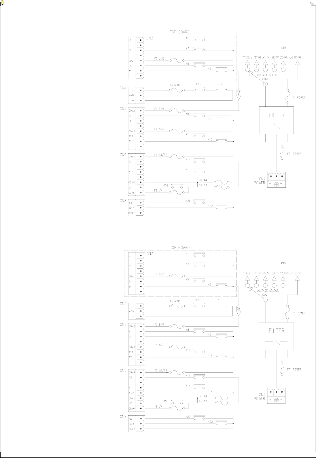
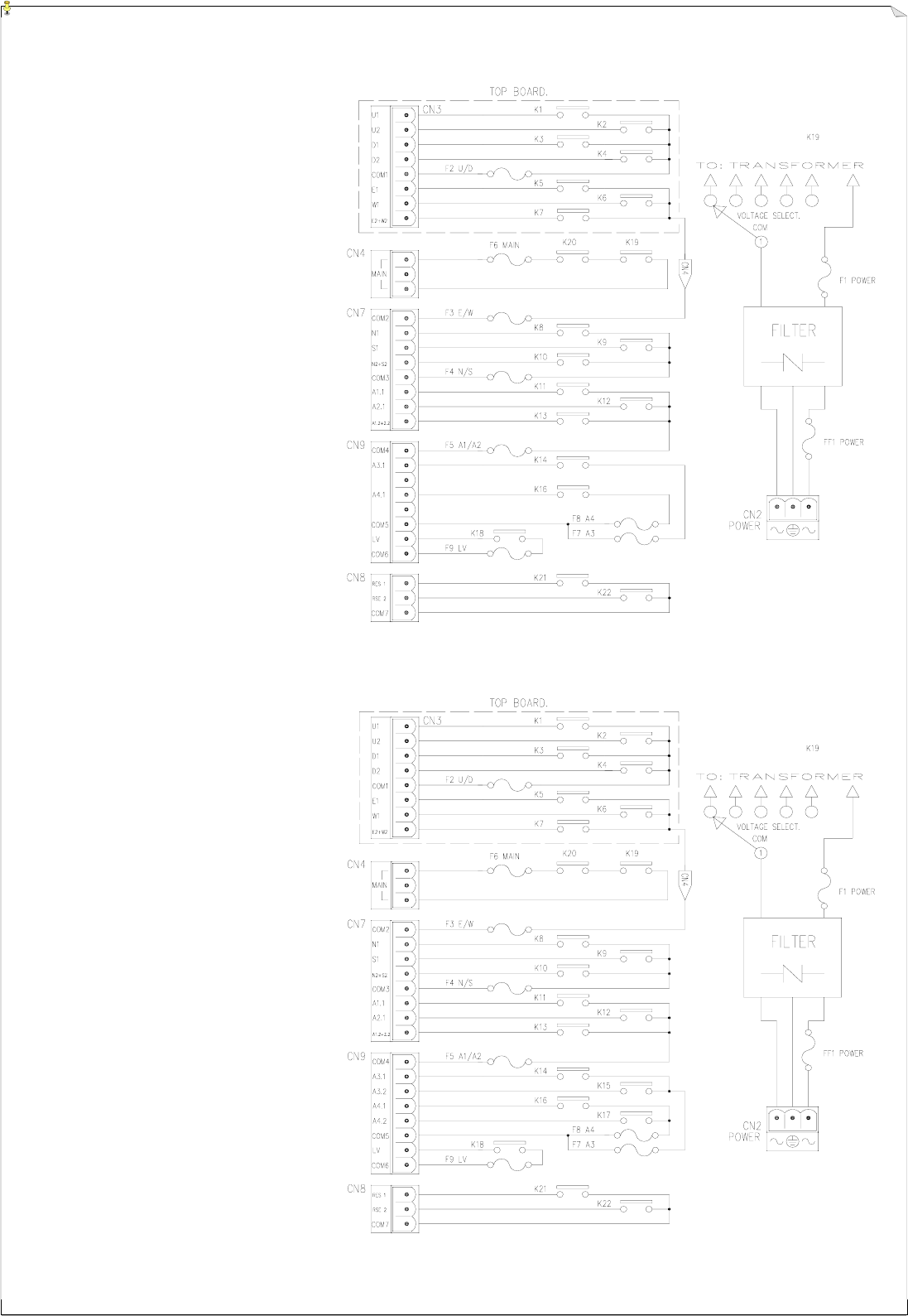
(Alpha 580E)
(Alpha 580F)
21
JP1
JP2
JP3
JP4
JP5
JP6
JP7
7
7.
.
S
SY
YS
ST
TE
EM
M
C
CO
ON
NF
FI
IG
GU
UR
RA
AT
TI
IO
ON
NS
S
7
7.
.1
1
H
Ho
ow
w
T
To
o
S
Se
et
t
J
Ju
um
mp
pe
er
r
F
Fu
un
nc
ct
ti
io
on
ns
s
(Fig. 19) Alpha 500 ~ 560 Models (Fig. 20) Alpha 580 Models
Manufacture Settings
Open
For Alpha 580 models only
1. After turning “on” the transmitter power, press START/AUX
pushbutton to activate the receiver MAIN.
2. After EMS Reset, press START/AUX pushbutton to activate the
receiver MAIN.
JP1
Short For all models
1. Turning “on” the transmitter power will activate the receiver MAIN.
2. Resetting the EMS will activate the receiver MAIN.
Open Reserved
JP2 Short Reserved
Open For all models
After 1 minute of transmitter low-voltage warning, the transmitter
power will be deactivated.
JP3
Short For all models
After 1minute of transmitter low-voltage warning, the transmitter power
“and” the receiver MAIN will be deactivated. (refer to note A below)
Open For Alpha 540A & 560A models
AUX button with normal momentary relay contact.
JP4 Short For Alpha 540A & 560A models
AUX button with latching relay contact.
Note A: If transmitter low-voltage condition occurs during operation the transmitter handset itself will display a visual warning by
blinking the status light red. Furthermore, the transmitter will also send out a special low-voltage command signal to the receiver
to activate its internal low-voltage (LV) warning relay. By connecting a horn, siren or lights to the LV relay output the operator
can be notified of a transmitter low-voltage condition. The LV relay will open and close at one-second intervals for up to a
minute warning the operator of the low-voltage condition. To insure maximum safety, both the transmitter power and the
receiver MAIN will be deactivated (depending on JP3 settings)
Note B: Every time when you change jumper settings you must first turn the receiver power “off” and then turn it back “on” so that the new
settings can be stored in memory.
FUSE
JP1 OPEN→JUMP
SHORT→JUMP
AC
DIP-SW
U
JP3
JP2
JP4
22
JP-1 Setting (for Alpha 580 models only)
JP1
Open
Power
“On”
Press START/AUX
pushbutton
Receiver MAIN
activated OR Reset EMS button Press START/AUX
pushbutton
Receiver MAIN
activated
JP4
Short
Power
“On” Receiver MAIN activated OR Reset EMS button Receiver MAIN activated
JP-3 Setting (for all models)
YES Work resumes
JP3
Open
Power
“On”
Work in
progress
Transmitter
low-voltage
condition occurs
LV
warning
Replace batteries
within 1 minute NO Transmitter unit will be deactivated
YES Work resumes
JP3
Short
Power
“On”
Work in
progress
Transmitter
low-voltage
condition occurs
LV
warning
Replace batteries
within 1 minute
NO The transmitter power and the
receiver MAIN will be deactivated
JP-4 Settings (for Alpha 540A & 560A models only)
JP4
Open AUX button with normal momentary relay contact
JP4
Short AUX button with latching/toggled relay contact
7
7.
.2
2
H
Ho
ow
w
t
to
o
S
Se
et
t
I
ID
D
C
Co
od
de
es
s
The ID code dip-switch is located on the backside of the transmitter encoder board and on the topside
of the receiver decoder/relay board (refer to section 3~5). When you change the ID code of the system
please make sure that the “1” value adds up to be an “odd” number (see below).
Example : ID code →
10001100
→ “1” x 3 = 3 → Odd number
→ Correct setting
Top slot → “1”
Bottom slot → “0”
N
No
ot
te
e:
:
D
De
ep
pe
en
nd
di
in
ng
g
o
on
n
a
ar
re
ea
a,
,
m
mo
od
de
el
ls
s
i
in
n
s
so
om
me
e
c
co
ou
un
nt
tr
ri
ie
es
s
m
ma
ay
y
h
ha
av
ve
e
“
“E
Ev
ve
en
n”
”
n
nu
um
mb
be
er
re
ed
d
I
ID
D
c
co
od
de
e.
.
P
Pl
le
ea
as
se
e
c
ch
he
ec
ck
k
t
th
he
e
I
ID
D
c
co
od
de
e
i
in
nf
fo
or
rm
ma
at
ti
io
on
n
l
lo
oc
ca
at
te
ed
d
o
on
n
t
th
he
e
b
ba
ac
ck
ks
si
id
de
e
o
of
f
t
th
he
e
t
tr
ra
an
ns
sm
mi
it
tt
te
er
r
h
ha
an
nd
ds
se
et
t
o
or
r
o
on
n
t
th
he
e
f
fa
ac
ce
e
c
co
ov
ve
er
r
o
of
f
t
th
he
e
r
re
ec
ce
ei
iv
ve
er
r
u
un
ni
it
t
f
fo
or
r
c
co
or
rr
re
ec
ct
t
I
ID
D
c
co
od
de
e
s
se
et
tt
ti
in
ng
g
(
(o
od
dd
d
o
or
r
e
ev
ve
en
n)
).
.
23
7
7.
.3
3
R
Re
ec
ce
ei
iv
ve
er
r
R
RF
F
C
Ch
ha
an
nn
ne
el
l
S
Se
et
tt
ti
in
ng
g
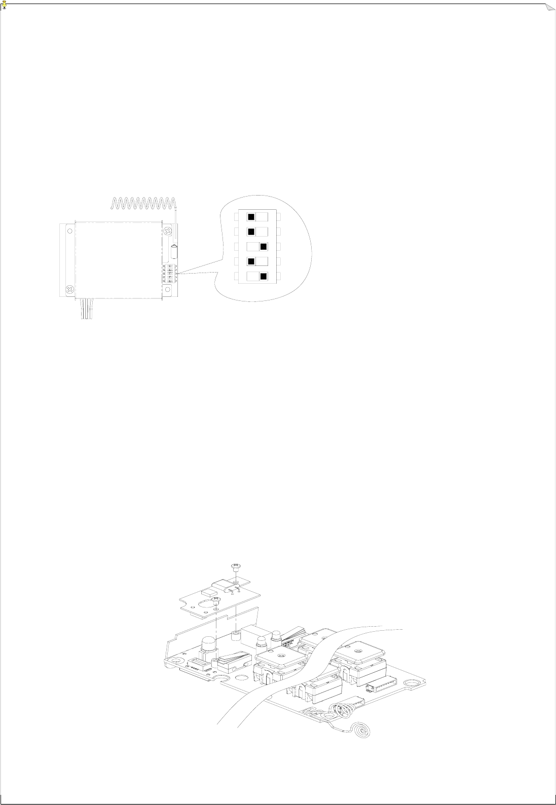
There are 30 sets of user-adjustable receiving RF channels that can be set manually via a 5-position
dip-switch located to the right of the receiving RF module. Change the receiving RF channel simply
by resetting these 5-position dip-switch. For the location of the receiving RF module, please refer to
fig. 15, 16, and 18 on page 11, 12, and 14.
Example: For the above dip-switch setting (
00101
) counting from dip-position #1 through #5, the above RF
channel would be “205”, which also represents frequency “301.205 MHz”. Please refer to the
frequency (RF) channel table on page 26 or the CHANNEL → DIP label located on the receiving RF
module itself.
7
7.
.4
4
H
Ho
ow
w
t
to
o
R
Re
em
mo
ov
ve
e
t
th
he
e
T
Tr
ra
an
ns
sm
mi
it
tt
ti
in
ng
g
R
RF
F
B
Bo
oa
ar
rd
d
The transmitter RF channel can be easily replaced or exchanged simply by replacing the small
removable RF board located atop the transmitter encoder board. The small RF board can be easily
removed by unscrewing the two small bolts that secured the RF board and the encoder board together
(refer to the diagram below). Please keep in mind that the RF channel of the transmitter must be
identical to the receiver. If the RF channel for both transmitter and receiver are different, please
readjust accordingly (refer to section 7.3 above).
12345
24
7
7.
.5
5
A
Al
lp
ph
ha
a
5
58
80
0
M
Mo
od
de
el
ls
s
P
Pu
us
sh
hb
bu
ut
tt
to
on
n
F
Fu
un
nc
ct
ti
io
on
n
S
Se
et
tt
ti
in
ng
gs
s
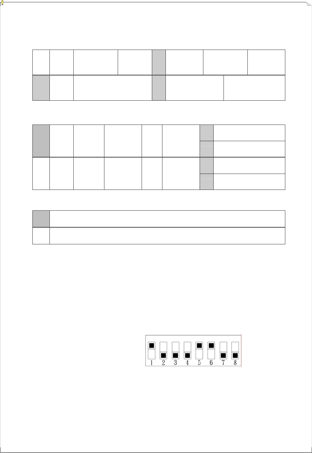
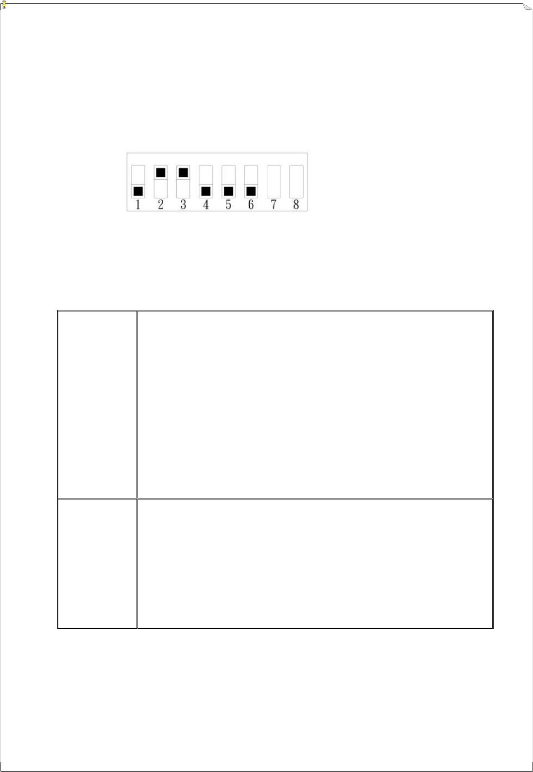
Numerous Alpha 580 models’ pushbutton contact relay settings can be set via an 8-position dip-switch
located on the receiver decoder/relay board (refer to fig. 18 on page 14).
DIP-1 → “0”
Example: DIP-2 → “1”
DIP-3 → “1”
DIP-4 → “0”
DIP-5 → “0”
DIP-6 → “0”
Top slot represents “1” value and lower slot represents “0” value.
Alpha 580 models dip-switch function table
Alpha 580A-1
&
Alpha 580A-2
DIP1 → “0” → pushbutton 1&2, 3&4, 5&6 interlocked
“1” → pushbutton 1&2, 3&4, 5&6 not interlocked
DIP2 → “0” → pushbuttons 7&8 interlocked
“1” → pushbutton 7&8 not interlocked
DIP3 → “0” → pushbutton 7&8 with momentary relay contact (DIP2 set at “1”)
“1” → pushbutton 7&8 with latching/toggled relay contact (DIP2 set at “1”)
DIP4 → “0” → pushbutton 9&10 interlocked
“1” → pushbutton 9&10 not interlocked
DIP5 → “0” → pushbutton 9 with momentary relay contact (DIP4 set at “1”)
“1” → pushbutton 9 with latching/toggled relay contact (DIP4 set at “1”)
DIP6 → “0” → 10th pushbutton with momentary relay contact (DIP4 set at “1”)
“1” → 10th pushbutton with latching/toggled relay contact (DIP4 set at “1”)
Alpha 580B
DIP1 → “0” → pushbutton 7&8 interlocked
“1” → pushbutton 7&8 not interlocked
DIP2 → “0” → pushbuttons 7 with momentary relay contact (DIP1 set at “1”)
“1” → pushbutton 7 with latching/toggled relay contact (DIP1 set at “1”)
DIP3 → “0” → pushbutton 8 with momentary relay contact (DIP1 set at “1”)
“1” → pushbutton 8 with latching/toggled relay contact (DIP1 set at “1”)
DIP4 → “0” → pushbutton 9 with momentary relay contact
“1” → pushbutton 9 with latching/toggled relay contact

25
Alpha 580 models dip-switch function table (continued)
Alpha 580C-1
&
Alpha 580C-2
DIP1 → “0” → pushbutton 1&2 with both 1st and 2nd speed contact relay
activated when pressed to 2nd speed (refer to note A)
“1” → pushbutton 1&2 with both 1st and 2nd speed contact relay
interlocked when pressed to 2nd speed (refer to note B)
DIP2&3 → “00” → pushbuttons 9 with momentary relay contact
“01” → pushbutton 9 with latching/toggled relay contact
“10” → pushbutton 9 with 3rd speed function (refer to note C)
DIP4 → “0” → pushbutton 10 with momentary relay contact
“1” → pushbutton 10 with latching/toggled relay contact
Alpha 580D
DIP1 → “0” → pushbutton 1&2 with both 1st and 2nd speed contact relay
activated when pressed to 2nd speed (refer to note A)
“1” → pushbutton 1&2 with both 1st and 2nd speed contact relay
interlocked when pressed to 2nd speed (refer to note B)
DIP2 & DIP3 must set to “0” at all time
Alpha 580E
DIP1 → “0” → pushbutton 1&2 with both 1st and 2nd speed contact relay
activated when pressed to 2nd speed (refer to note A)
“1” → pushbutton 1&2 with both 1st and 2nd speed contact relay
interlocked when pressed to 2nd speed (refer to note B)
DIP2 → “0” → pushbuttons 7&8 interlocked
“1” → pushbutton 7&8 not interlocked
DIP3 → “0” → pushbutton 7 with momentary relay contact (DIP2 set at “1”)
“1” → pushbutton 7 with latching/toggled relay contact (DIP2 set at “1”)
DIP4 → “0” → pushbutton 8 with momentary relay contact (DIP2 set at “1”)
“1” → pushbutton 8 with latching/toggled relay contact (DIP2 set at “1”)
DIP5&6 → “00” → pushbutton 9 with momentary relay contact
“01” → pushbutton 9 with latching/toggled relay contact
“10” → pushbutton 9 with 3rd speed function (refer to note C)
Alpha 580F
DIP1 → “0” → pushbutton 1&2 with both 1st and 2nd speed contact relay
activated when pressed to 2nd speed (refer to note A)
“1” → pushbutton 1&2 with both 1st and 2nd speed contact relay
interlocked when pressed to 2nd speed (refer to note B)
DIP2&3 → “00” → pushbutton 9 with momentary relay contact
“01” → pushbutton 9 with latching/toggled relay contact
“10” → pushbutton 9 with 3rd speed function (refer to note C)
Note A: This setting is ideal for majority of the crane systems (manufacture preset). When pressed to 2nd speed for the hoist motion, the 1st
speed contact relay will remain engaged (closed) along with the 2nd speed contact relay.
Note B: This setting is ideal for crane system with dual-motor hoist. When pressed to 2nd speed for the hoist motion, the 1st speed contact
relay will be disengaged (open), with only the 2nd speed contact relay engaged (closed).
Note C: During operation, when a particular command pushbutton is in the 2nd speed position (pushbutton fully pressed), pressing the 10th
pushbutton once will activate the 3rd speed contact relay. If the operator presses the 10th pushbutton again, the command
pushbutton currently in use will return to the 2nd speed position.

26
7
7.
.6
6
F
Fr
re
eq
qu
ue
en
nc
cy
y
(
(R
RF
F)
)
C
Ch
ha
an
nn
ne
el
ls
s
T
Ta
ab
bl
le
e
FREQUENCY DIP-SWITCH SETTING RF CHANNEL
301.105 MHz 00001 201
301.130 MHz 00010 202
301.155 MHz 00011 203
301.180 MHz 00100 204
301.205 MHz 00101 205
301.230 MHz 00110 206
301.255 MHz 00111 207
301.280 MHz 01000 208
301.305 MHz 01001 209
301.330 MHz 01010 210
301.355 MHz 01011 211
301.380 MHz 01100 212
301.405 MHz 01101 213
301.430 MHz 01110 214
301.455 MHz 01111 215
301.480 MHz 10000 216
301.505 MHz 10001 217
301.530 MHz 10010 218
301.555 MHz 10011 219
301.580 MHz 10100 220
301.605 MHz 10101 221
301.630 MHz 10110 222
301.655 MHz 10111 223
301.680 MHz 11000 224
301.705 MHz 11001 225
301.730 MHz 11010 226
301.755 MHz 11011 227
301.780 MHz 11100 228
301.805 MHz 11101 229
301.830 MHz 11110 230

27
8
8.
.
R
RE
EC
CE
EI
IV
VE
ER
R
I
IN
NS
ST
TA
AL
LL
LA
AT
TI
IO
ON
N
8
8.
.1
1
P
Pr
re
ep
pa
ar
ra
at
ti
io
on
n
F
Fo
or
r
I
In
ns
st
ta
al
ll
la
at
ti
io
on
n
1. Required Tools for Receiver Installation:
(1) Flat Head Screwdriver (-)
(2) Phillips Head Screwdriver (+)
(3) Multi-Meter
(4) 14mm Wrench x 2
(5) Power Drill with 10.5mm Drill-Bit
2. Check to ensure that your receiver is not set to the same RF channel and ID code as any
other systems in operation at the same facility or within 300-meter distance.
3. Prior to installation, make sure that the crane or equipment itself is working properly.
4. Use a multi-meter to check the voltage source available and ensure the receiver voltage
setting matches your power source.
5. Prior to installation, switch off the main power source to the crane or equipment.
8
8.
.2
2
S
St
te
ep
p-
-B
By
y-
-S
St
te
ep
p
I
In
ns
st
ta
al
ll
la
at
ti
io
on
n
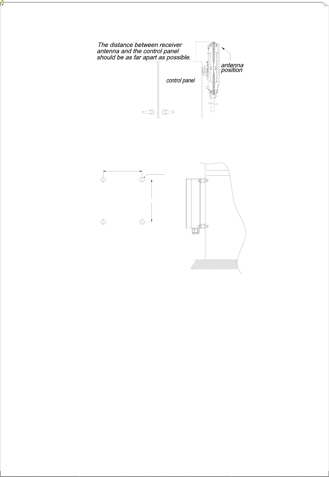
1. For better reception, the location selected should have the antenna visible from all areas
where the transmitter is to be used.
2. The location selected should not be exposed to high levels of electrical noise. Mounting the
receiver next to an unshielded variable frequency control (inverter) may cause minor
interference. Always locate the receiver unit as far away from inverter controls as possible.
3. Ensure the selected location has adequate space to accommodate the receiver enclosure.
4. Make sure the receiver unit is in upright position (vertical).
5. The distance between the antenna and the control panel should be as far apart as possible
(refer to fig. 21 and fig. 22 on page 28).
6. If a crane or equipment’s runway is longer than 100 meters, an external antenna should be
added. The Alpha 500 series’ receiver housing has provisions for an external factory
installed antenna available as an option, contact your dealer for price and delivery.
7. Alpha 500 ~ 560 models: Drill a hole on the control panel (10.5mm).
Alpha 580 models: Drill 4 holes on the control panel (10.5mm).
8. Tightened the bolt nuts provided.
9. If the control panel has a plastic surface, extended grounding wire should be used.
10. For system wiring, please refer to the output contact diagrams from page 15~20.
11. Ensure all wiring is correct and safely secured and all screws are fastened.
28
255mm
278mm
4- O10.5
(Fig. 21) Alpha 500 ~ 560 Models
(Fig. 22) Alpha 580 Models
8
8.
.3
3
S
Sy
ys
st
te
em
m
T
Te
es
st
ti
in
ng
g
1. Connect the power source to the receiver and test the MAIN relay output by pressing the red
emergency stop button (EMS) and observe that it properly opens and closes the main line
disconnect contactor.
2. Test the operation of each function to ensure it corresponds to the transmitter direction
labels and/or the pendant it is replacing.
3. Test the limit switches on the hoist and/or crane and verify they are working properly.
4. If your new remote control is replacing an existing pendant, make sure it is completely
disconnected to prevent unwanted control commands, i. e. snick circuits.
5. If your new remote control is replacing an existing pendant make sure it is stored in a safe
location where it will not interfere with remote operation (get torn off).
29
9
9.
.
T
TR
RA
AN
NS
SM
MI
IT
TT
TE
ER
R
O
OP
PE
ER
RA
AT
TI
IO
ON
N
1. Batteries _ Make sure the two “AA” alkaline batteries are installed correctly. Use 2000mA rated
alkaline-type batteries for optimum operating time between replacements. If rechargeable-type
batteries are used, for optimum operating time, choose ones rated above 1600mA.
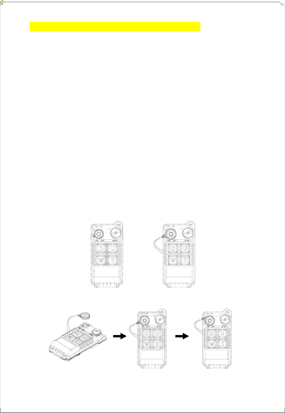
2. Startup Procedure _ There are two types of transmitter power key-switch available for the
Alpha 500 series, the standard fixed type (refer to fig. 23) and the optional removable type (refer
to fig. 24). Basically both key types operate in the same fashion depending on personal
preference and safety regulations. For the below illustrations the optional removable-type power
key is used.
Elevate the red EMS button by twisting it 1/4 turn clockwise; it will pop up. Then insert the
transmitter power key onto the key-switch slot located on the top left-hand corner of transmitter
handset (refer to fig. 25). Make sure the black arrow marking on the power key is pointed
directly towards the “OFF” marking on the transmitter handset. To turn on the transmitter power,
just rotate the power key clockwise to “ON” position. The Status LED located at the center of the
power switch will display a green blinking light for up to 40 seconds when the power key is
turned to “ON” position. At this time the receiver MAIN relay is also activated. After 40 seconds
of inactivity, that is 40 seconds after the last pushbutton is released, the green light will disappear
thus temporarily deactivating the transmitter power and the receiver MAIN. Pressing any
pushbutton thereafter will close the receiver MAIN and start the timing sequence over again.
This important safety feature is designed to ensure that the transmitter handset and the receiver
MAIN will be in "power off" position if the operator forgets to turn off the transmitter power, or if
the transmitter unit is left unattended in the work area.
(Fig. 23) Fixed On/Off key (Fig. 24) Removable On/Off key
(Fig. 25) Removable power key installation procedure

30
LED DISPLAY
3. Status Lights _ If the transmitter Status LED displays a red blinking light that is “on” → 0.1
second and “off” → 2.0 seconds, or no light at all, this indicates that the two “AA” batteries in the
transmitter must be replaced. For battery replacement please refer to instruction next page.
If the transmitter Status LED is blinking red, “on” → 2.0 seconds and “off” → 0.1 second, it
means that the transmitter handset is locked due to a damaged or closed pushbutton contact. Also
possibly the operator is pressing a pushbutton while going through the start up sequence. This
important safety feature is designed to prevent any unexpected crane movement at system startup
caused by closed or defective pushbutton contacts.
If the transmitter Status LED displays a constant red light without flashing, this indicates that the
transmitter ID code is set incorrectly (refer to section 7.2 on page 22).
4. EMS & Restarting _ In case of an emergency, press down the red emergency stop button (EMS)
will immediately deactivates the transmitter and receiver MAIN relay. To reactivate the system,
just turn the EMS button clockwise 1/4 turn so that the red button pops up (refer to fig. 26 below).
(Fig. 26) EMS Button
5. Shutting Off the Transmitter _ To disconnect the transmitter power and the receiver MAIN
relay, just turn the transmitter power to “OFF” position. When the transmitter power is turned off,
the receiver MAIN is also deactivated (open).
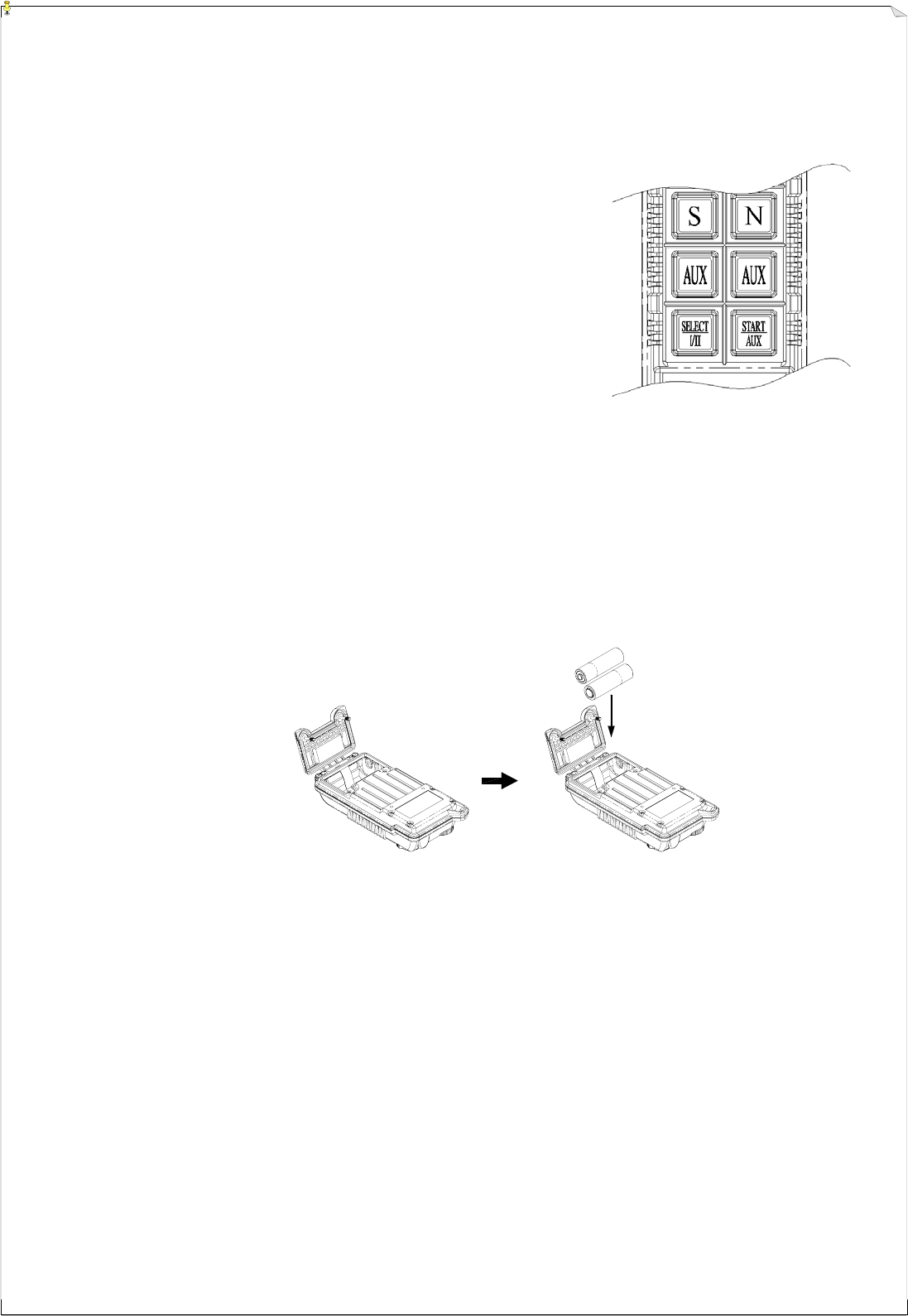
6. Models with 3-Stage SELECT Function _ When the transmitter power key is turned “on”,
LED-I will light up indicating only the main hoist and/or trolley is activated. To activate the
auxiliary hoist and/or trolley, just press the "Select" pushbutton one time, the LED display will
switch from LED-I to LED-II, indicating only the auxiliary hoist and/or trolley is activated. Press
the "Select" pushbutton again to have both main and auxiliary hoist and/or trolley activated at the
same time (both LED-I and LED-II lit). When both LED-I and LED-II are lit, pressing any
pushbutton will result in duplicate movement for the main and auxiliary hoist and/or trolley.
Example: Both main and auxiliary hoist will go up at the same time when “UP” ( ↑)
pushbutton is pressed.
To switch back to the main hoist and/or trolley, just press the "Select" pushbutton again. Please
note that every time when the transmitter power is turned “off” and then back “on” again, or after
EMS reset, the "Select " setting will default back to LED-I with main hoist and/or trolley active.
31
1) Power "on" → LED-I "lit” → Main hoist and/or trolley
activated.
2) Press “Select” button once → LED-II "lit" → Auxiliary
hoist and/or trolley activated.
3) Press “Select” button again → both LED-I & II "lit" →
Both main and auxiliary hoist and/or trolley activated with
duplicate movements.
4) Press “Select” button again → “Select” mode returned to
LED-I with only the main hoist and/or trolley activated.
7. Interlocking Pushbuttons _ Each set of motion is interlocked to its self so no conflicting
commands can take place. For example, pressing the hoist UP (↑) and DOWN (↓) button
simultaneously will result in no command signal being sent.
8. Battery Changing _ To change batteries, just unscrew the battery cover located on the backside
of the transmitter handset with a (+) screwdriver. When changing new batteries, make sure that
the batteries are installed correctly. The marking inside the battery compartment will tell you
which side is positive (+) charge and which side is negative (-). After changing the batteries,
make sure all screws are tightened.
9. Transmission Data _ The data of the Alpha 500 series are carried out by the power-saving PCDT
method of transmission (Pause Continuous Data Transmission). The duration of each PCDT
transmission is set at 40 seconds, with option for 3 minutes (please contact your dealer for more
details). During this 40-second PCDT transmission, the transmitter unit will only send out "zero
position command" to the receiver if the operator gives no active commands (pushbutton not
pressed). If no active commands are given after 40 seconds, that is 40 seconds after the last
pushbutton is released, the receiver MAIN will be temporarily deactivated (open). The receiver
MAIN can only be reactivated when the receiver unit receives an active command from the
transmitter unit by pressing the pushbuttons. Furthermore, if the system encountered strong radio
interference or if the transmitter is out of the receiving range during operation, to insure operating
safety, the receiver MAIN relay will also be temporarily deactivated.

32
1
10
0.
.
T
TR
RO
OU
UB
BL
LE
E
S
SH
HO
OO
OT
TI
IN
NG
G
Should the operator find the equipment not operating normally, please check the chart below for simple
trouble shooting tips.
PROBLEM POSSIBLE REASON SOLUTION
Transmitter does
not communicate
with the receiver.
Transmitter and the receiver are
not on the same RF channel
(SQ lamp not lit) or ID code.
Ensure the correct transmitter is
in use. The labels on the receiver
and the transmitter will identify the
RF channel and ID code in use.
Transmitter does
not communicate
with the receiver.
Low or no transmitting power
from the transmitter unit.
Turn “on” the transmitter with
EMS elevated. If the status LED
shows blinking red light or no
light at all, then turn the power
“off” and replace the two alkaline
“AA” batteries.
No power to the
receiver (AC power
indicator on the
receiver unit not lit).
Blown fuse or no input power
connection.
Ensure power input to the receiver
unit is correct. If the power indicator
(AC) is still not lit, please check the
receiver for any open fuse.
Outputs do not
operate correctly.
Receiver configuration is not set
properly or output wiring is incorrect.
Please refer to section 6 and 7
to ensure receiver is correctly wired
and configured for your application.
Transmitter does
not communicate
with the receiver.
Transmitter is turned on with the
EMS activated (pressed down).
Elevate the EMS first and then
turn the power switch off and
then on again.
Receiver System Status LED Display
(Refer to fig.15/16/18 on page 11/12/14)
TYPE LED INDICATION PROBLEM AND SOLUTION
EEPROM error – reprogramming required.
1 Constant red light. Incorrect receiver ID code setting (see note below).
2 ON → 1.0 second
OFF → 1.0 second
ID code not matched on both the transmitter and
receiver unit, please readjust accordingly.
3 Dim or no light. Under-voltage, check the main power-supply.
4 ON → 2.0 seconds
OFF → 0.1 second MAIN contact relay jammed or defective.
5 ON → 0.1 second
OFF → 2.0 seconds
System normal with transmitter pushbutton either in
neutral or in transmitter power “off” position.
6 ON → 0.1 second
OFF → 0.1second
System normal with transmitter pushbutton in
non-neutral position (pushbutton depressed).
Note: Please refer to section 7.2 on page 22 for correct ID code setting.

33
1
11
1.
.
S
SY
YS
ST
TE
EM
M
S
SP
PE
EC
CI
IF
FI
IC
CA
AT
TI
IO
ON
N
Transmitter Unit
Frequency Range : 301 MHz
Transmitting Range : 100 meters
Hamming Distance : 6
Channel Spacing : 25KHz
Frequency Control : Quartz Crystals
Frequency Drift : < 5ppm @ -25℃ ~ +75℃
Frequency Deviation : < 1ppm @ 25℃
Spurious Emission : - 50dB
Transmitting Power : ~1mW
Emission : F1D
Antenna Impedance : 50 ohms
Enclosure Rating : IP-66
Source Voltage : 3.0V (“AA” alkaline batteries x 2)
Current Drain : 10 ~ 18mA
Operating Temperature : -25℃ ~ +75℃
Dimension (500~520 Models) : 140mm x 68mm x 33mm
(540~560 Models) : 173mm x 68mm x 33mm
(580 Models) : 213mm x 68mm x 33mm
Weight (500~520 Models) : 200g (include batteries)
(540~560 Models) : 240g (include batteries)
(580 Models) : 290g (include batteries)
Receiver Unit
Frequency Range : 301 MHz
Channel Spacing : 25KHz
Hamming Distance : 6
Frequency Control : Synthesizer (PLL)
Frequency Drift : < 5ppm @ -25℃ ~ +75℃
Frequency Deviation : < 1ppm @ 25℃
Sensitivity : -120dBm
Antenna Impedance : 50ohms
Data Decoder Reference : Quartz Crystals
Responding Time : 40ms (Normal)
Enclosure Rating : IP-65 (Alpha 500~560 Models)
IP-66 (Alpha 580 Models)
Source Voltage : AC 220V ~ 230V @ 50/60 Hz.
Power Consumption : 11VA
Operating Temperature : -25℃ ~ +75℃
Output Contact Rating : 250V @ 10A
Dimension (500~560 Models) : 310mm x 134mm x 72mm
(580 Models) : 300mm x 230mm x 86mm
Weight (500~520 Models) : 1,625g (include output cable)
(540~560 Models) : 1,700g (include output cable)
(580 Models) : 3,400g (no output cable)

34
1
12
2.
.
P
PA
AR
RT
TS
S
L
LI
IS
ST
T
1. 301 MHz Transmitting RF Board (All Models) BTX301
2. Encoder Board (Alpha 500) BEN500
Encoder Board (Alpha 520) BEN520
Encoder Board (Alpha 540S) BEN540S
Encoder Board (Alpha 540A) BEN540A
Encoder Board (Alpha 560S) BEN560S
Encoder Board (Alpha 560A) BEN560A
Encoder Board (Alpha 580A-1) BEN580A1
Encoder Board (Alpha 580A-2) BEN580A2
Encoder Board (Alpha 580B) BEN580B
Encoder Board (Alpha 580C-1) BEN580C1
Encoder Board (Alpha 580C-2) BEN580C2
Encoder Board (Alpha 580D) BEN580D
Encoder Board (Alpha 580E) BEN580E
Encoder Board (Alpha 580F) BEN580F
3. 301 MHz Receiving RF Module (All Models) BRX301
4. Decoder/Relay Board (Alpha 500) BDR500
Decoder/Relay Board (Alpha 520) BDR520
Decoder/Relay Board (Alpha 540S) BDR540S
Decoder/Relay Board (Alpha 540A) BDR540A
Decoder/Relay Board (Alpha 560S) BDR560S
Decoder/Relay Board (Alpha 560A) BDR560A
Decoder/Relay Board (Alpha 580A-1) BDR580A1
Decoder/Relay Board (Alpha 580A-2) BDR580A2
Decoder/Relay Board (Alpha 580B) BDR580B
Decoder/Relay Board (Alpha 580C-1) BDR580C1
Decoder/Relay Board (Alpha 580C-2) BDR580C2
Decoder/Relay Board (Alpha 580D) BDR580D
Decoder/Relay Board (Alpha 580E) BDR580E
Decoder/Relay Board (Alpha 580F) BDR580F
5. Transmitter Enclosure (Alpha 500 & 520 Models) BCT500
Transmitter Enclosure (Alpha 540S & 560S Models) BCT560S
Transmitter Enclosure (Alpha 540A & 560A Models) BCT560A
Transmitter Enclosure (Alpha 580A, C, D Models) BCT580A
Transmitter Enclosure (Alpha 580B, E, F Models) BCT580B
6. Receiver Enclosure (Alpha 500 & 520 Models) BCR500
Receiver Enclosure (Alpha 540 & 560 Models) BCR560
Receiver Enclosure (Alpha 580 Models) BCR580

35
7. Double-Step Pushbutton (All Models) B50001
Single-Step Pushbutton (All Models) B50002
8. EMS Red Cap (All Models) EMS01
9. Wrist Strap (Alpha 500 ~ 560 Models) WS01
Waist Belt (Alpha 580 Models) WB01
10. Pushbutton Rubber Boot (Alpha 500 & 520 Models) PRB01
Pushbutton Rubber Boot (Alpha 540 & 560 Models) PRB02
Pushbutton Rubber Boot (Alpha 580 Models) PRB03
11. Pushbutton Direction labels (All Types) DL01
12. Transformer (12/24VDC – Alpha 500 ~ 560 Models) T24VDC
Transformer (24VAC – Alpha 500 ~ 560 Models) T24VAC
Transformer (48VAC – Alpha 500 ~ 560 Models) T48VAC
Transformer (110/120VAC – Alpha 500 ~ 560 Models) T120VAC
Transformer (220/230 VAC – Alpha 500 ~ 560 Models) T230VAC
Transformer (380VAC – Alpha 500 ~ 560 Models) T380VAC
Transformer (12/24VDC – Alpha 580 Models) SSB-2601
Transformer (AC 110V~120V / 220V~240V – Alpha 580 Models) SSB-2603
Transformer (AC 350V~380V / 400V~460V – Alpha 580 Models) SSB-2604
Transformer (AC 24V/32V/46V/48V – Alpha 580 Models) SSB-2665
13. Regular Output Contact Relay (All Models) RLY01
Safety MAIN Contact Relay (All Models) RLY02
14. Protective Vinyl Casing (Alpha 500 ~ 560 Models) VPC01
Protective Vinyl Casing (Alpha 540 ~ 560 Models) VPC02
15. Leather Pouch (Alpha 500 ~ 520 Models) LP500
Leather Pouch (Alpha 540 ~ 560 Models) LP560
16. 2-meter Output Cable with 1 Common Circuit (Alpha 500 ~ 560 Models) OC500
2-meter Output Cable with 1 Common Circuit (Alpha 540 ~ 560 Models) OC501
2-meter Output Cable with 2 Common Circuits (Alpha 540 ~ 560 Models) OC502
2-meter Output Cable with 3 Common Circuits (Alpha 500 ~ 520 Models) OC503
2-meter Output Cable with 4 Common Circuits (Alpha 540 ~ 560 Models) OC504
17. Receiver Mounting Spring + Hardware (Alpha 500 ~ 560 Models) RMS500
Receiver Shock Absorbers + Mounting Hardware (Alpha 580 Models) RSA580
18. Optional External 301 MHz Antenna (All Models) ANT301
19. BNC Jack for External Antenna Connection (Alpha 500 ~ 560 Models)BNC500
BNC Jack for External Antenna Connection (Alpha 580 Models) BNC580
20. BNC Lead Wire for External Antenna Connection BLW500
21. 2-meter Coaxial Cable for External Antenna Connection (All Models) CC500
22. Removable Transmitter Power Key (All Models) KEY01