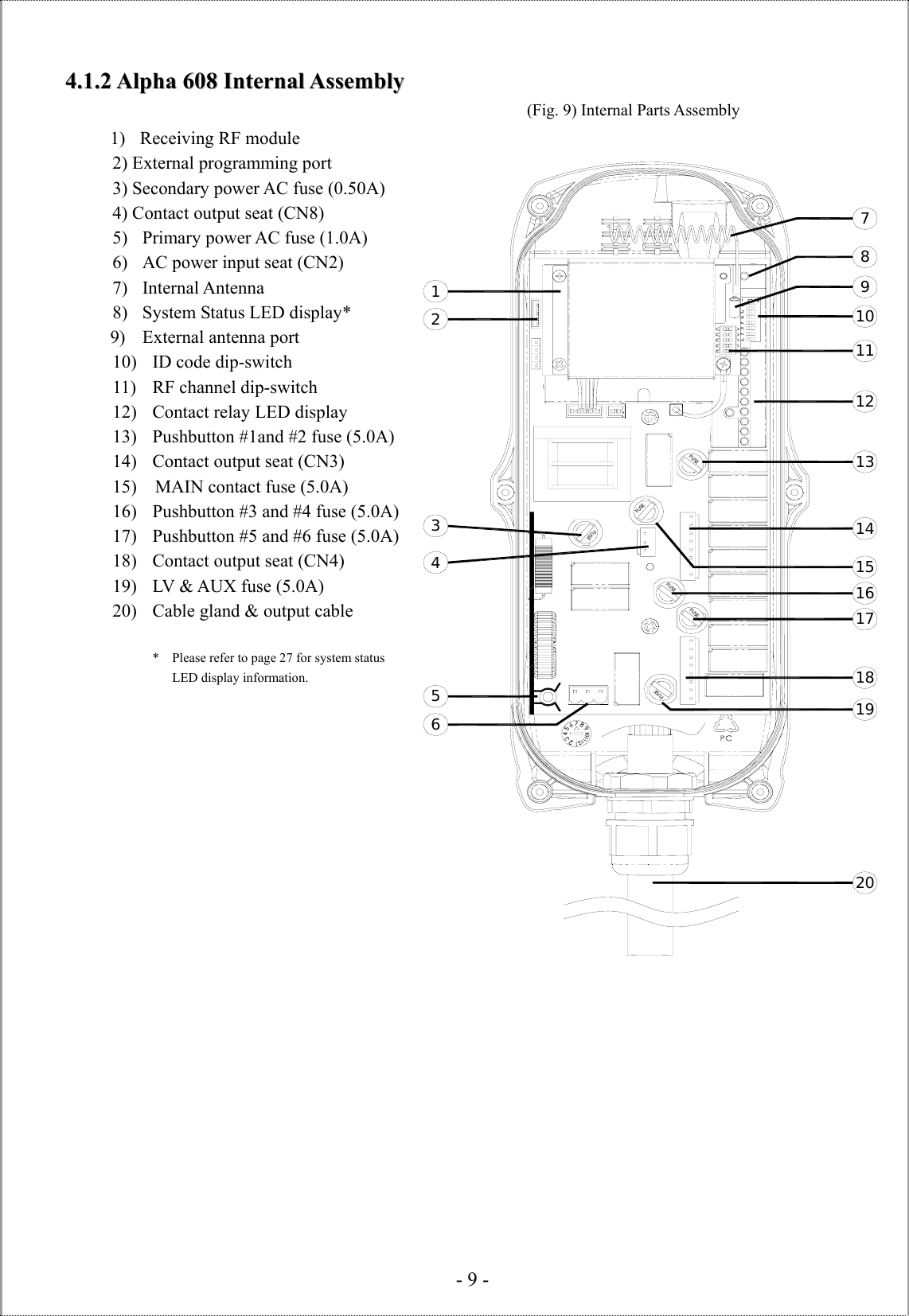
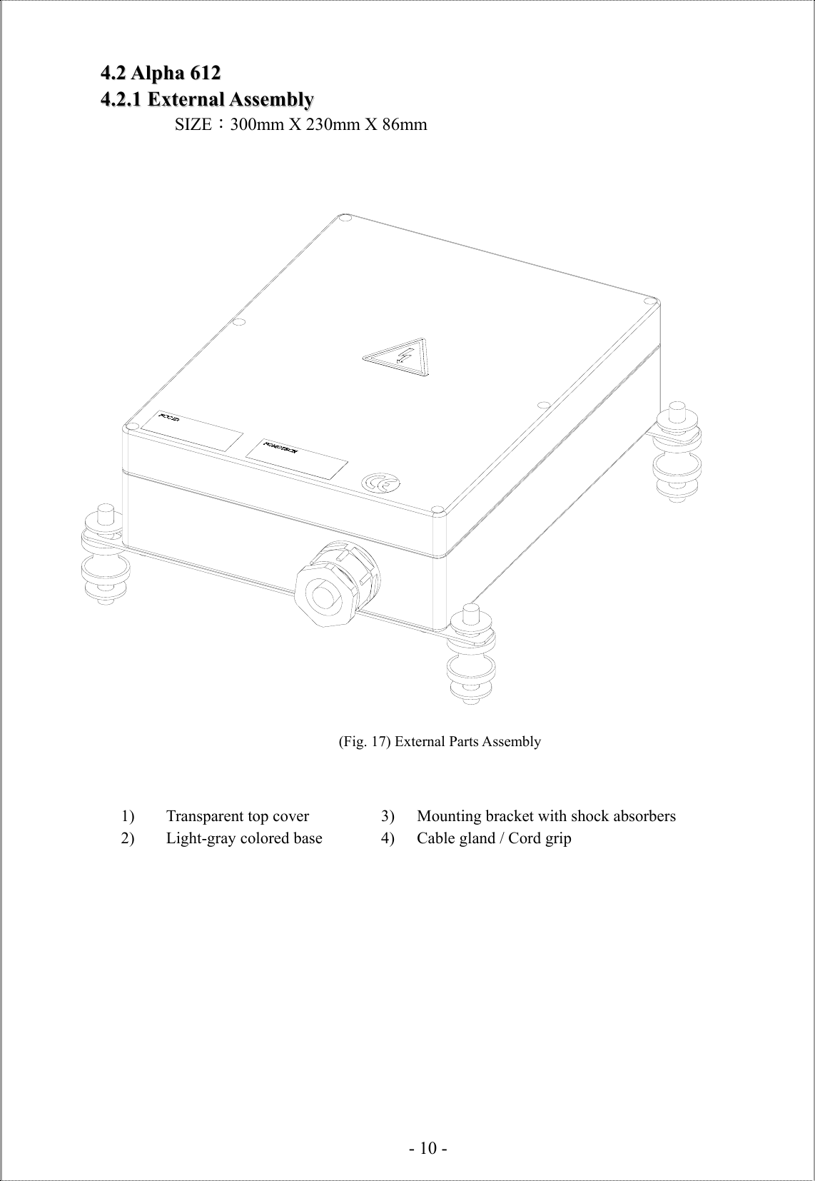
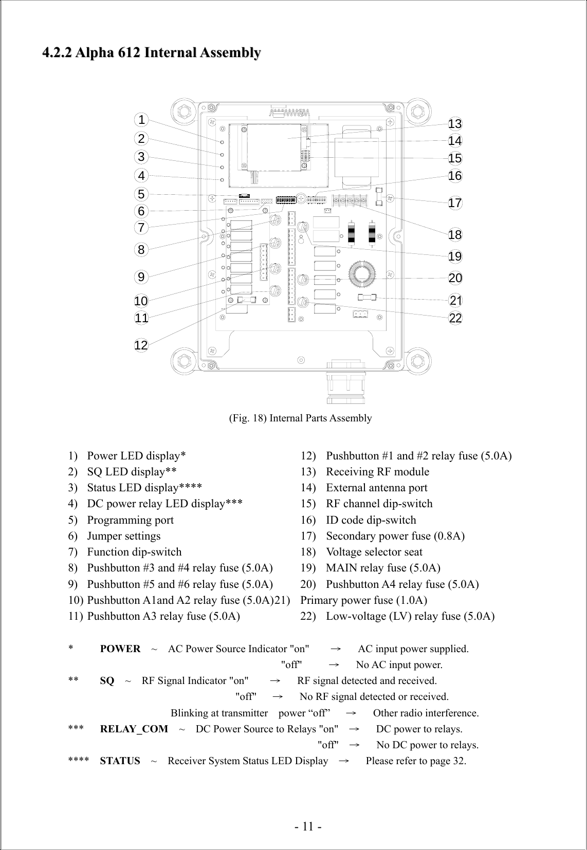
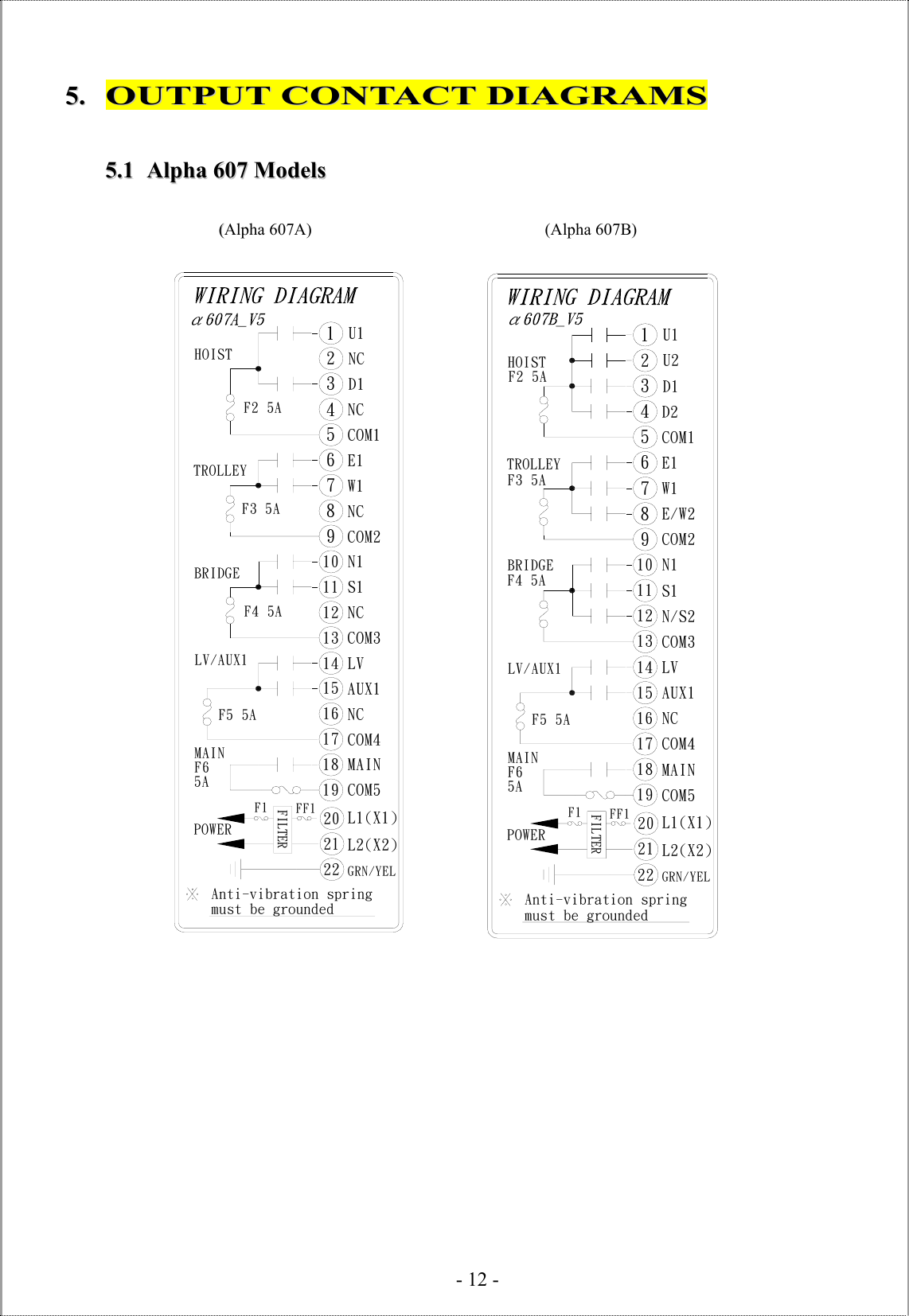
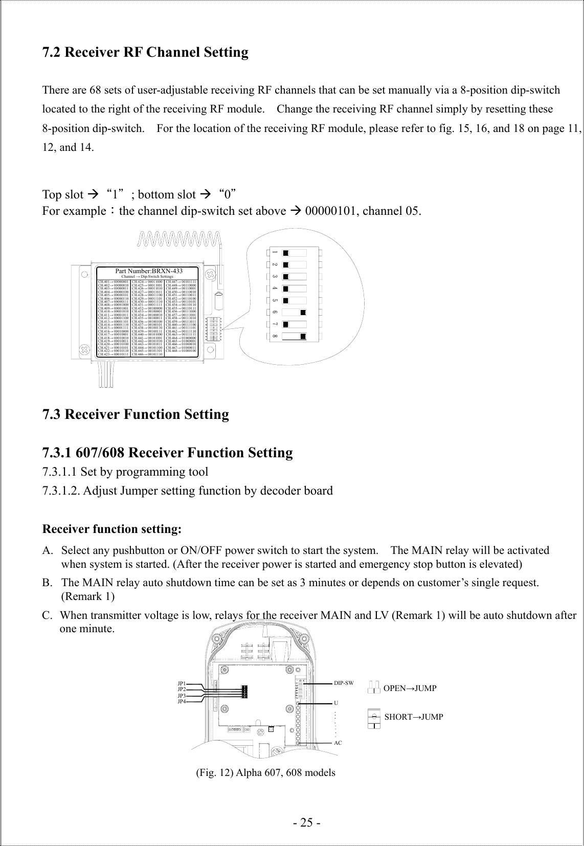
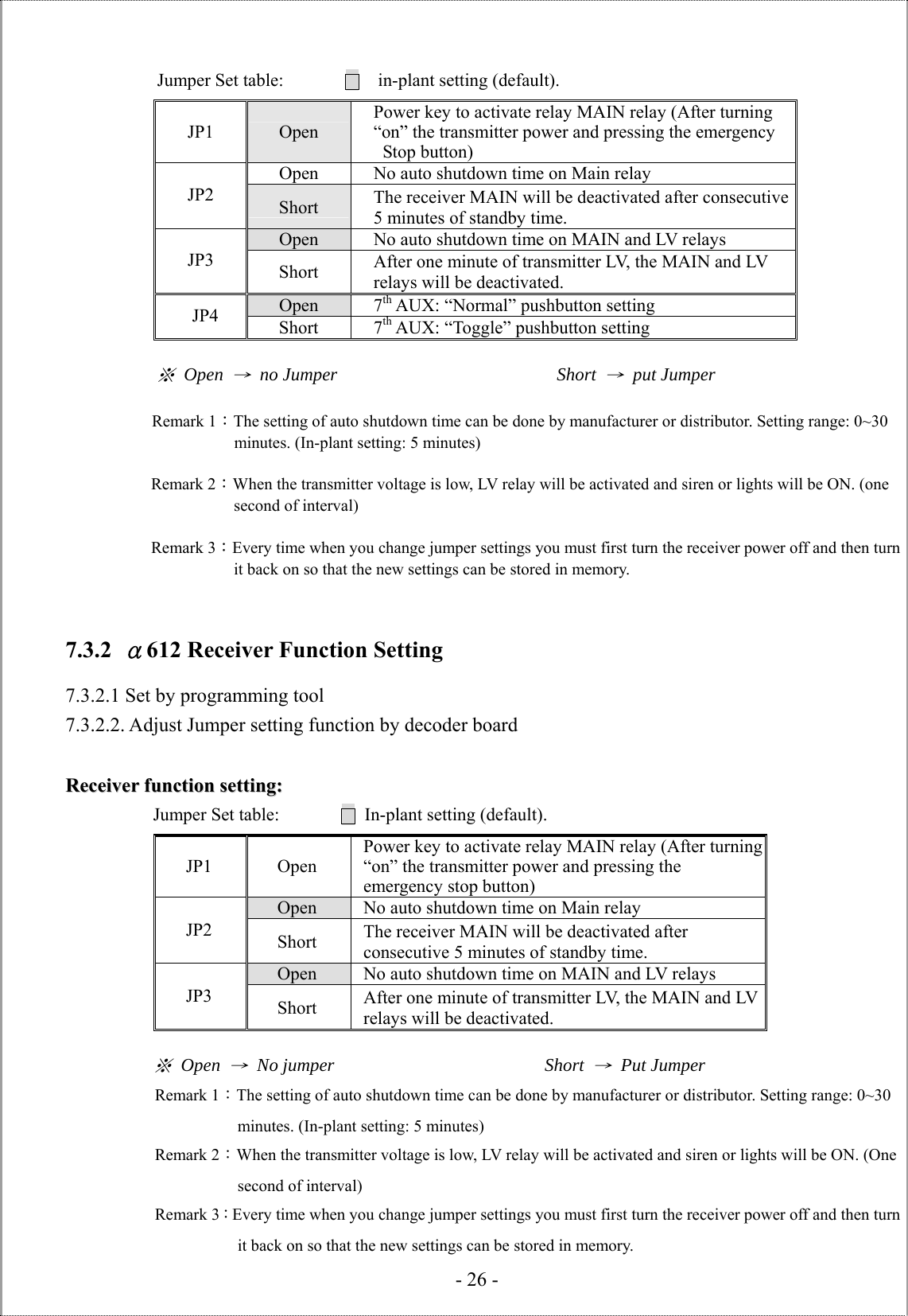
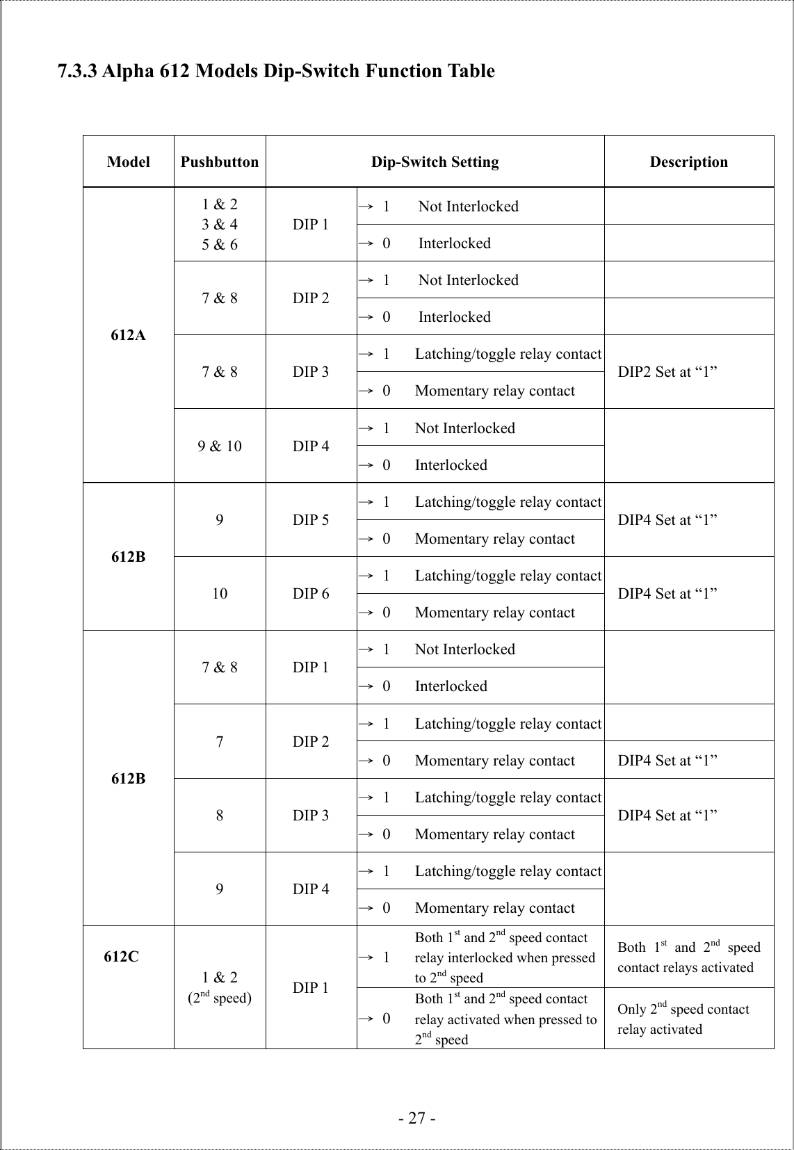
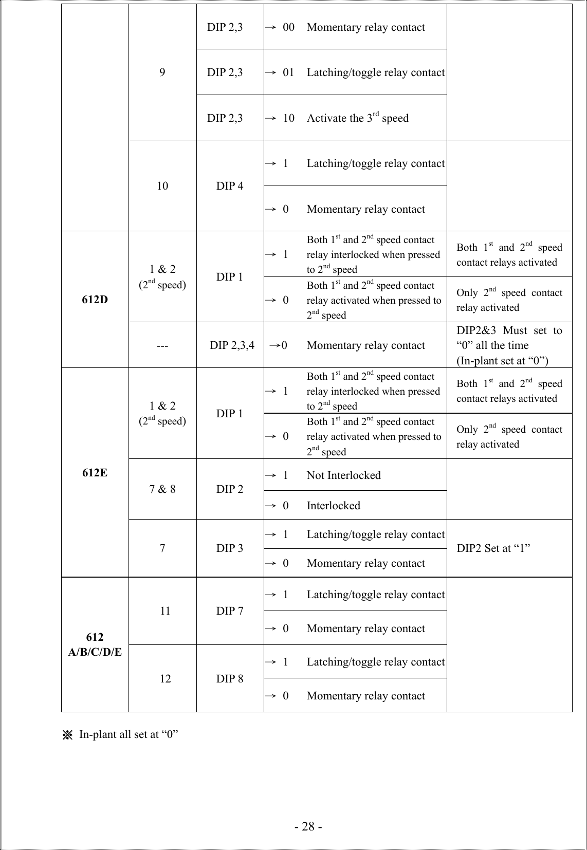
Fomotech ALPHA612SERIES Industrial Remote Control User Manual
Fomotech International Corp. Industrial Remote Control
UserManual.wiki
>
Fomotech
>
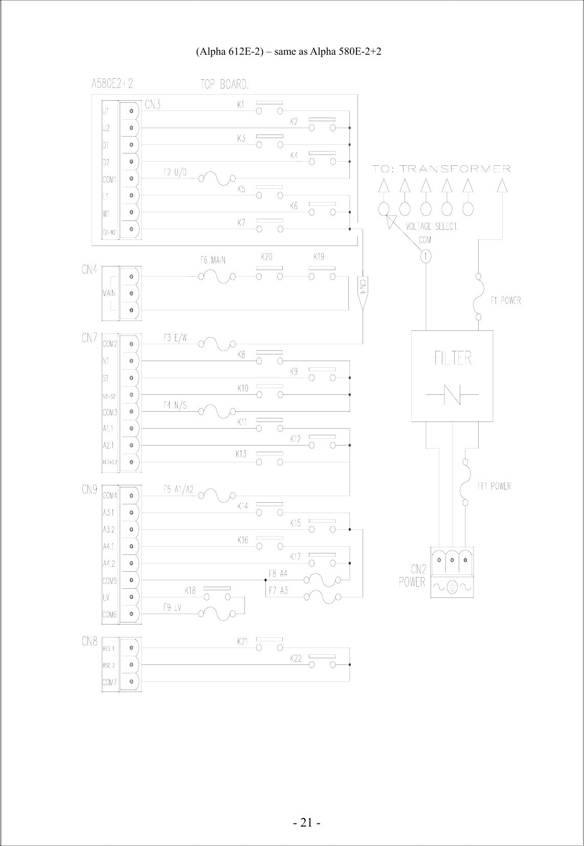
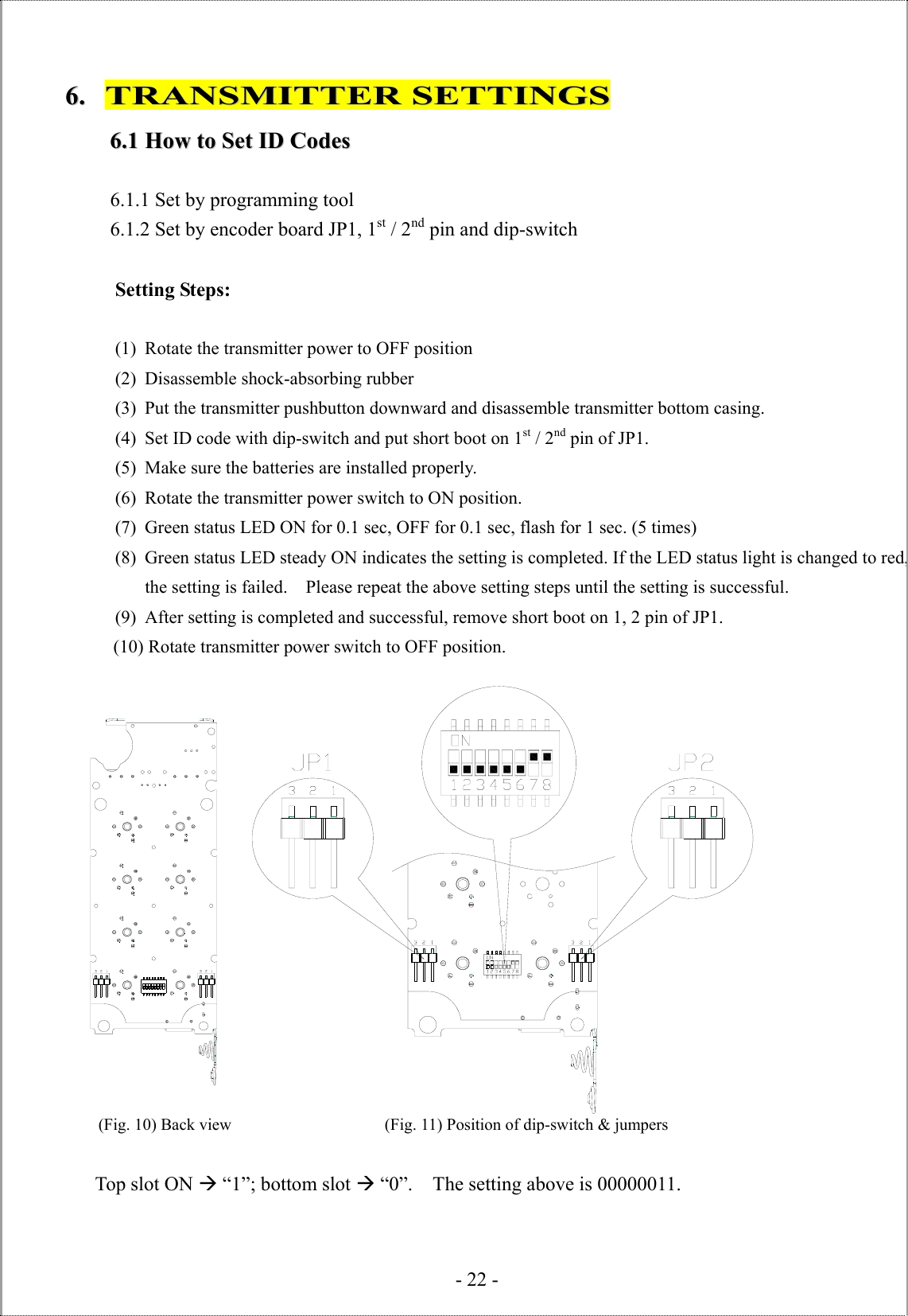
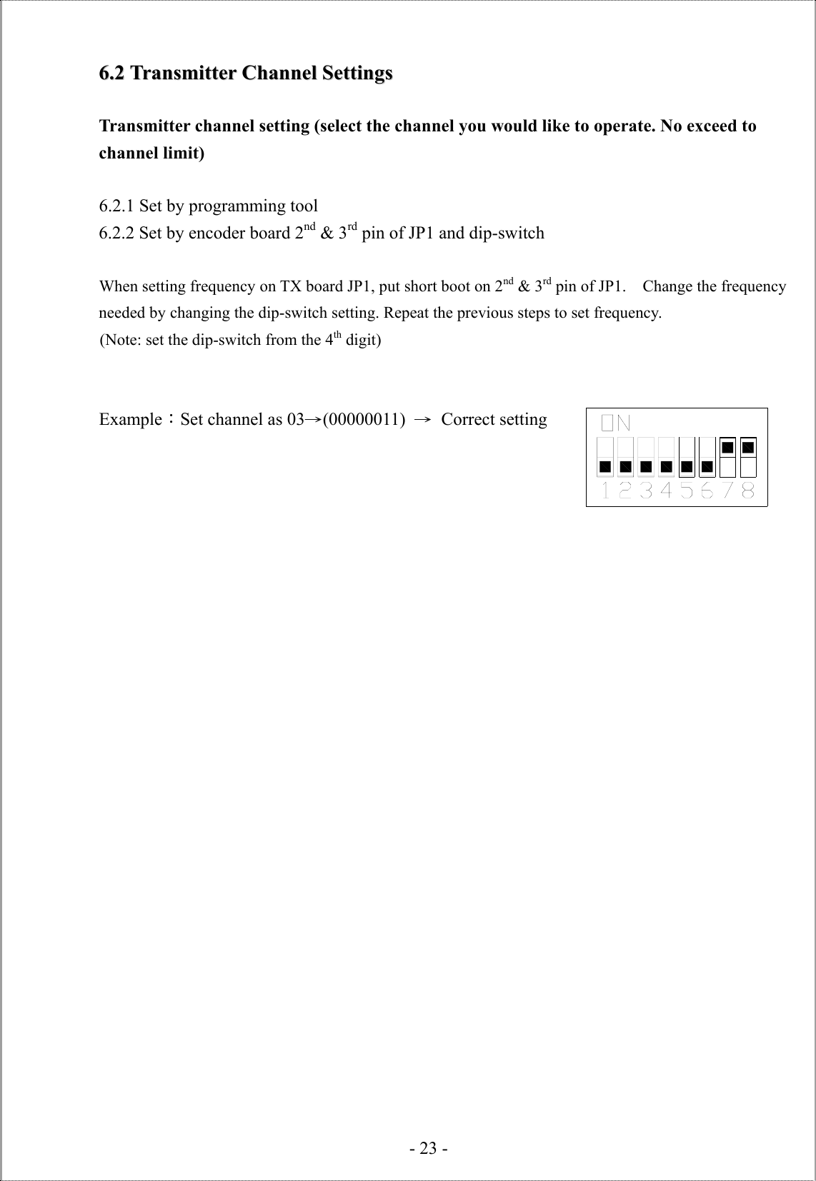
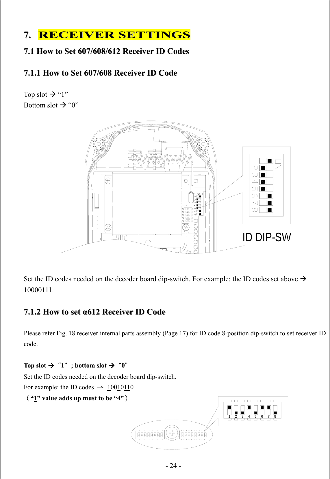
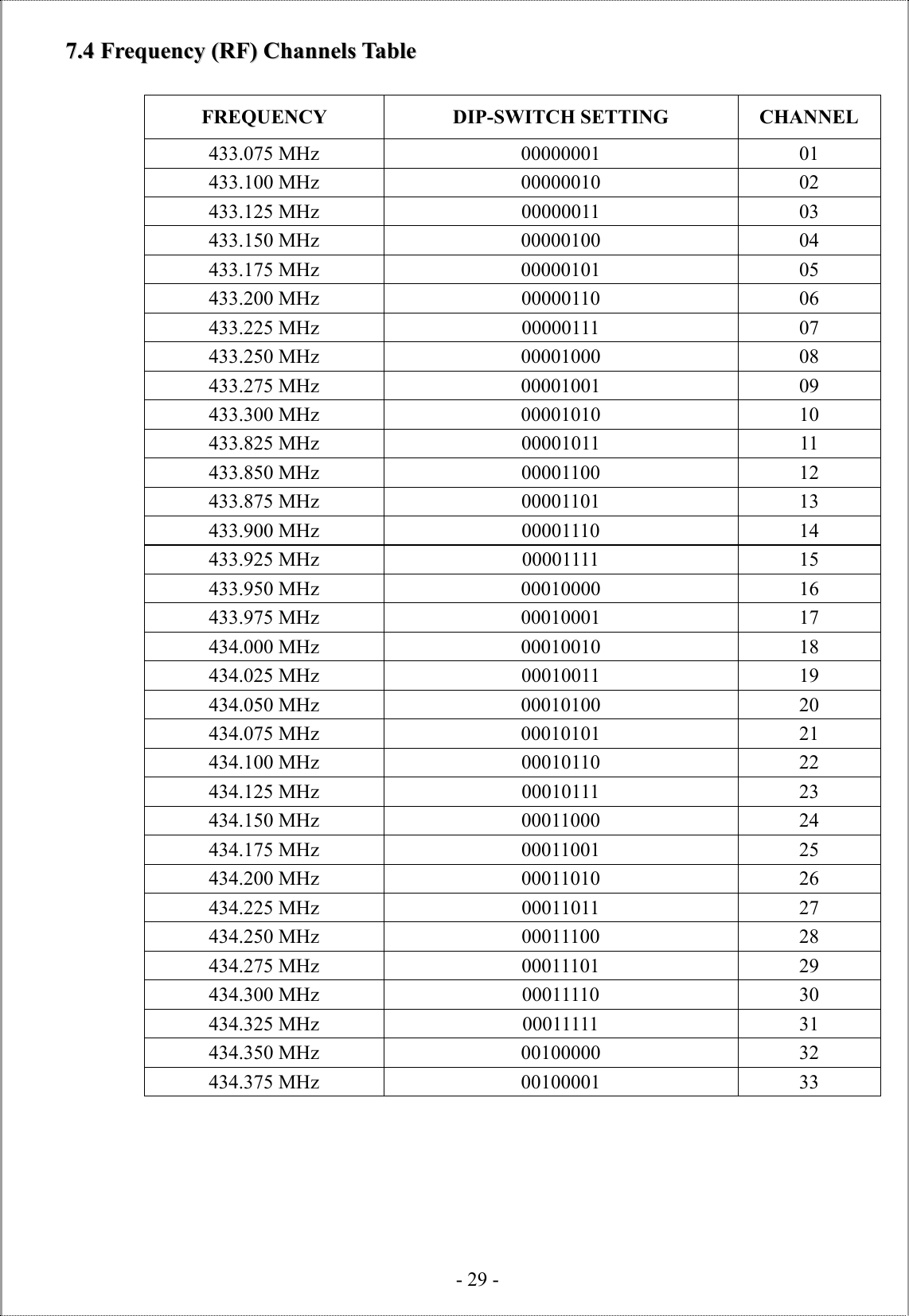
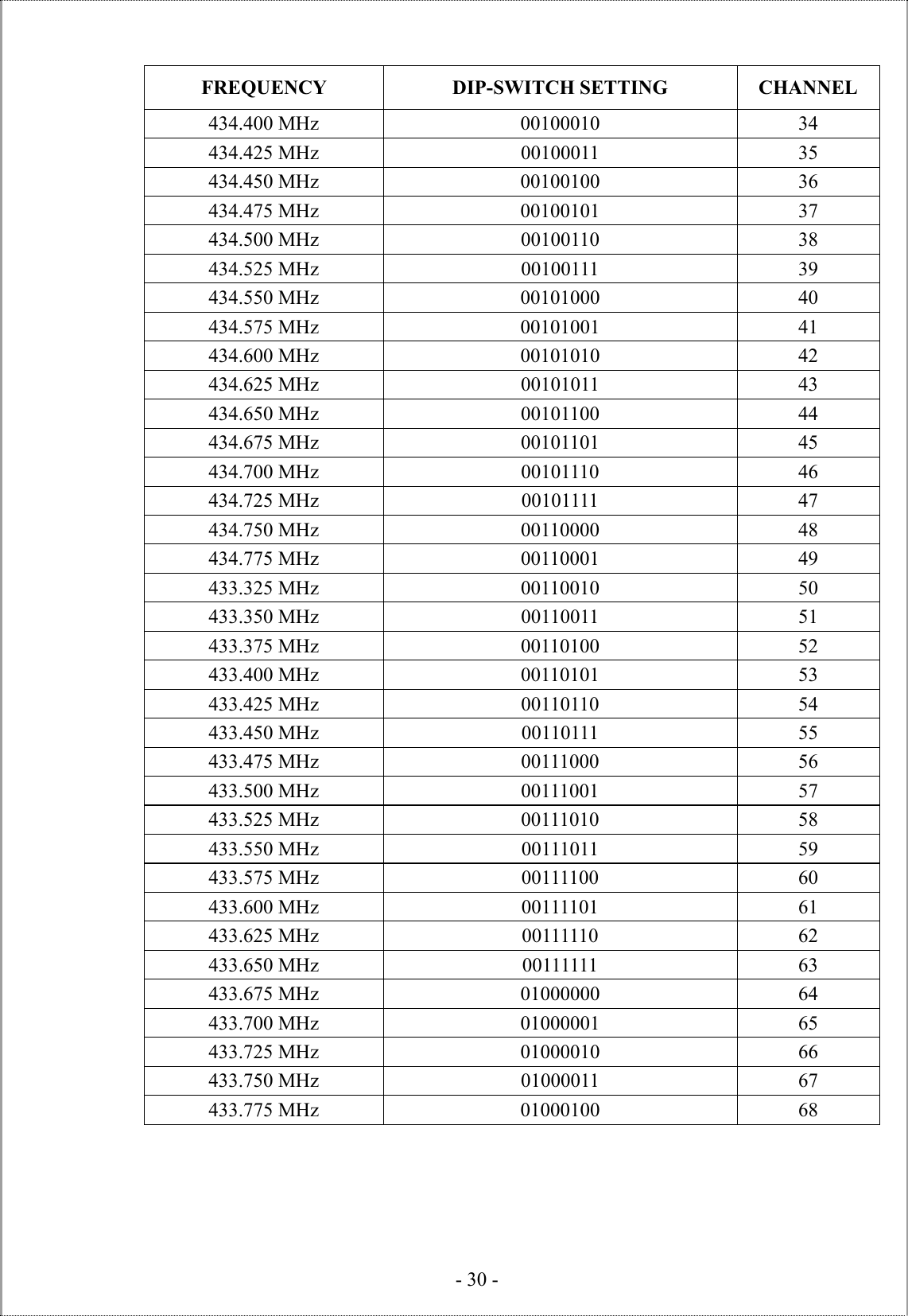
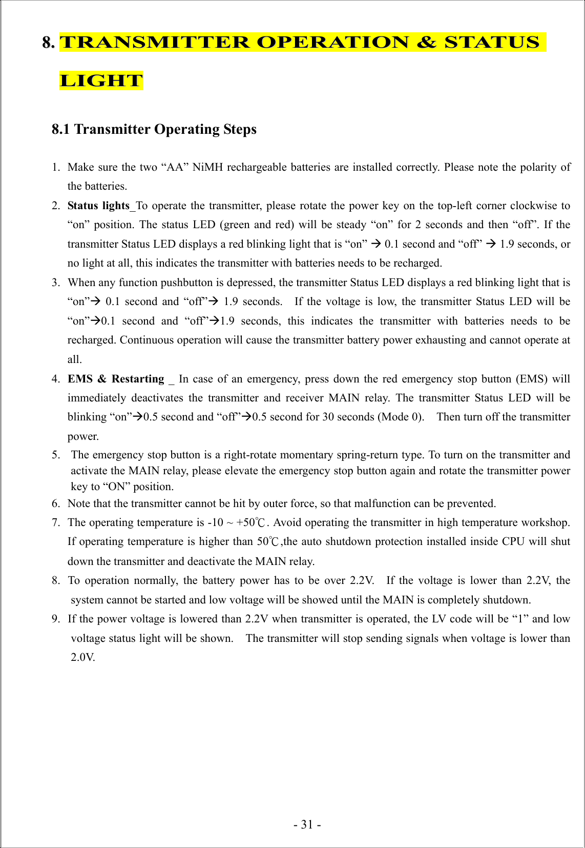
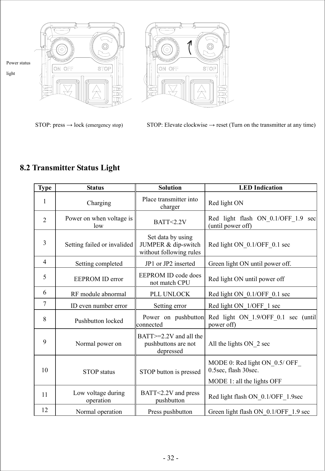
ALPHA612SERIES User Manual
User manual
Navigation menu
Upload a User Manual
Namespaces
Wiki Guide
HTML
PDF
Info
Views
User Manual
Discussion / Help
Navigation