Fomotech ALPHA612SERIES Industrial Remote Control User Manual
Fomotech International Corp. Industrial Remote Control
Fomotech >
User manual

- 1 -
T
TA
AB
BL
LE
E
O
OF
F
C
CO
ON
NT
TE
EN
NT
TS
S
Page
1. SAFETY INSTRUCTION ............................................................................................. 2
2. PUSHBUTTON CONFIGURATION
2.1 Alpha 607 & 608 Models ..................................................................................... 3
2.2 Alpha 612 Models ............................................................................................... 4
3. TRANSMITTER OUTLINE
3.1.1 Alpha 607 & 608 Models ..................................................................................... 5-6
3.1.2 Alpha 612 Models ............................................................................................. 6-7
3.2 Alpha 607/608/612 Spare Parts ...................................................................... 8
4. RECEIVER OUTLINE
4.1 Alpha 607 & 608 Models Internal Assembly ....................................................... 8-9
4.2 Alpha 612 Models Internal Assembly ................................................................... 10-11
5. OUTPUT CONTACT DIAGRAMS
5.2 Alpha 607 Models ................................................................................................. 12-13
5.3 Alpha 608 Models ................................................................................................. 14
5.4 Alpha 612 Models ................................................................................................. 15-19
6. SYSTEM CONFIGURATIONS
6.1 How to Set ID Codes ............................................................................................. 22
6.2 Transmitter RF Channel Setting ............................................................................. 23
7. RECEIVER SETTING
7.1 How to Set Receiver ID Codes .............................................................................. 24
7.2 Receiver RF Channel Setting .............................................................................. 25
7.3 Receiver Function Setting .............................................................................. 25
7.4 Frequency (RF) Channels Table .............................................................................. 29
8. TRANSMITTER OPERATION & STATUS LIGHT
8.1 Transmitter Operating Steps .............................................................................. 31
8.2 Transmitter Status light .............................................................................. 32
9. RECEIVER INSTALLATION
9.1 Preparation For Installation ................................................................................... 33
9.2 Step-By-Step Installation ....................................................................................... 33
9.3 System Testing ....................................................................................................... 34
9.4 Receiver System Status LED Display..................................................................... 35
10. TROUBLE SHOOTING................................................................................................. 37
11. SYSTEM SPECIFICATION ........................................................................................ 38
12. PARTS LIST ................................................................................................................. 39

2
1.
S
SA
AF
FE
ET
TY
Y
I
IN
NS
ST
TR
RU
UC
CT
TI
IO
ON
N
The Alpha 600 series are relatively simple to use, however, it is very important to observe the proper
safety procedures before, during, and after operation. When used properly, the Alpha 600 series will
enhance safety, productivity and efficiency in the workplace.
The following procedures should be strictly followed:
1. The transmitter is equipped with a specialized battery charger. Only two ”AA” Ni-MH rechargeable
batteries are allowed to be used in the transmitter. Please note the polarity of the batteries. Do not
use other types of battery to prevent any accident
2. Do not change the IDs on transmitter encoder and receiver decoder boards at will.
3. Check the transmitter casing and pushbuttons daily. Should any damage that could inhibit the
proper operation of the transmitter be found the unit should be immediately removed from service.
4. The red emergency stop button (EMS) should be checked at the beginning of each shift to ensure it is
in proper working order and the “Stop” command is being received by the receiver.
5. In the event of an emergency press down the EMS button will immediately deactivates the receiver
MAIN relay and the transmitter power. Then turned the power “off ” from the main power source to
the crane or equipment.
6. Do not use the same RF channel and ID code as any other system in use at the same facility or within
300-meter distance.
7. Ensure the waist belt is worn at all time during operation to avoid accidental damage to the
transmitter.
8. Rotate the power switch to OFF position when the transmitter is not operated temporarily or the
operation is finished.
9. Any repair or adjustment should be proceeding by repair technician for radio remote controls.
10. The operator should not change any electrical parts at will.
Changes or modifications are not expressly approved by the manufacturer could void the user's authority to
operate the equipment.
This device complies with EMC Directive 89/336/EEC, Low Voltage Directive 76/23/EEC and R&TTE
Directive 1995/5/EEC.This product has been approved for upper directives and covers the following
countries : Austria, Belgium, Cyprus, Czech Republic, Denmark, Estonia, Finland, France, Germany, Greece,
Hungary, Ireland, Italy, Latvia, Lithuania, Luxembourg, Malta, Poland, Portugal, Slovakia, Slovenia, Spain,
Sweden, The Netherlands, UK, Iceland, Norway, Switzerland, Turkey & Romania.
- 3 -
2.
P
PU
US
SH
HB
BU
UT
TT
TO
ON
N
C
CO
ON
NF
FI
IG
GU
UR
RA
AT
TI
IO
ON
N
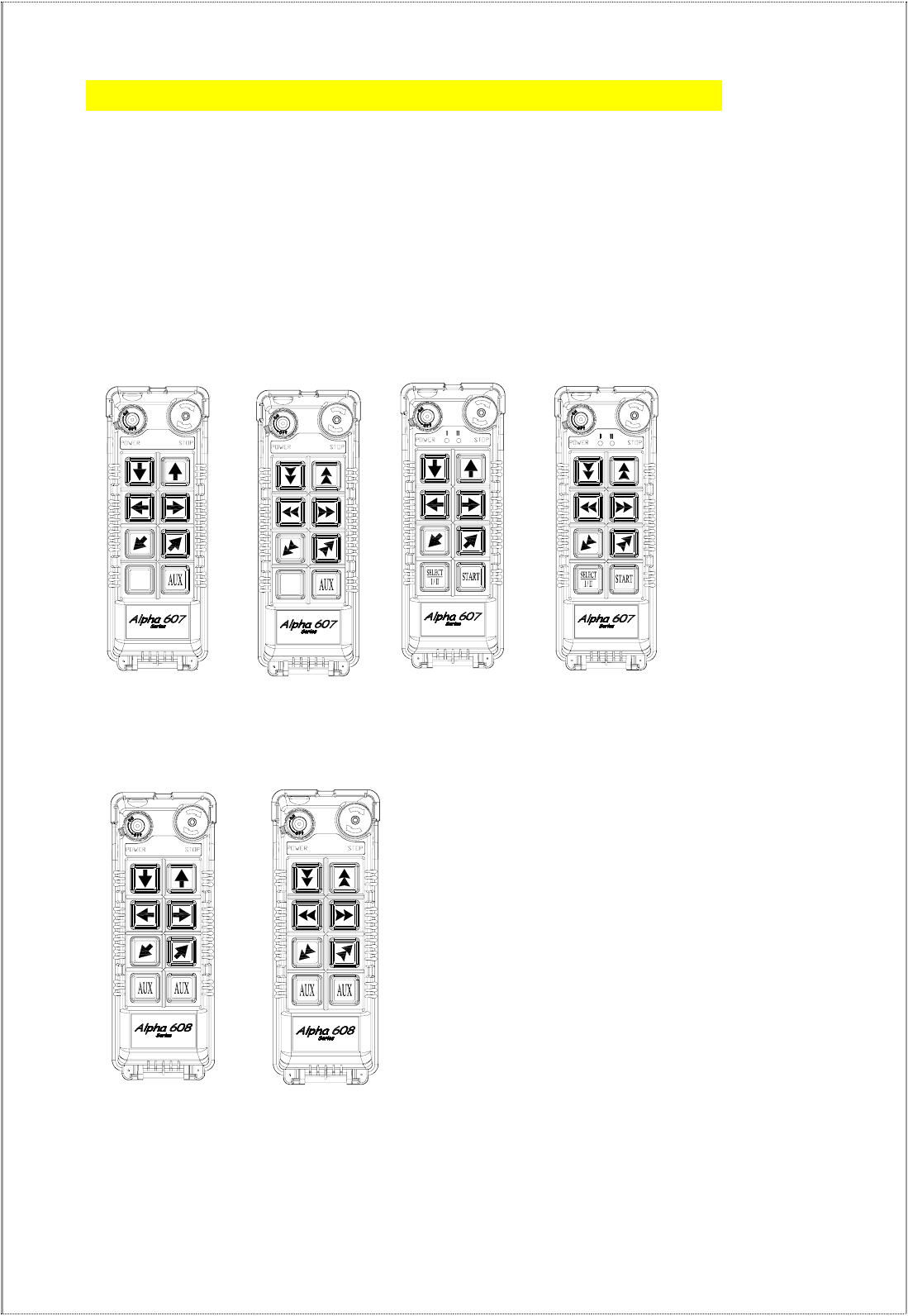
2.1 Alpha 607 & 608 Models
1. α607A -- (7) single speed pushbuttons
2. α607B -- (6) double speed pushbuttons + (1) single speed pushbuttons
3. α607AT -- (6) single speed pushbuttons + (1) SELECT I/II pushbutton
4. α607BT -- (6) double speed pushbuttons + (1) SELECT I/II pushbutton
5. α608A -- (8) single speed pushbuttons
6. α608B -- (6) double speed pushbuttons + (2) single speed pushbuttons
(Alpha 607A) (Alpha 607B) (Alpha 607AT) (Alpha 607BT)
(Alpha 608A) (Alpha 608B)
- 4 -
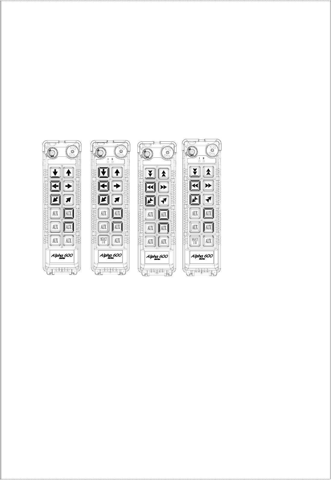
2.2 Alpha 612 Models
1. Alpha 612A → (12) one-speed pushbuttons
2. Alpha 612B → (11) one-speed pushbuttons + I/II select pushbutton*
3. Alpha 612C-1 → (6) two- speed + (6) one-speed pushbuttons
4. Alpha 612C-2 → (8) two-speed + (4) one-speed pushbuttons
5. Alpha 612D → (10) two-speed + (2) one-speed pushbuttons
6. Alpha 612E-1 → (6) two-speed + (5) one-speed pushbuttons + I/II select pushbutton*
7. Alpha 612E-1 → (8) two-speed + (3) one-speed pushbuttons + I/II select pushbutton*
* For cranes with auxiliary hoist and trolley (changeover function).
STOPPOWER STOPPOWER STOPPOWER STOPPOWER
α612C-1
α612C-2
α612D
α612E-1
α612E-2
α612A α612B
- 5 -
3
3.
.
T
TR
RA
AN
NS
SM
MI
IT
TT
TE
ER
R
O
OU
UT
TL
LI
IN
NE
E
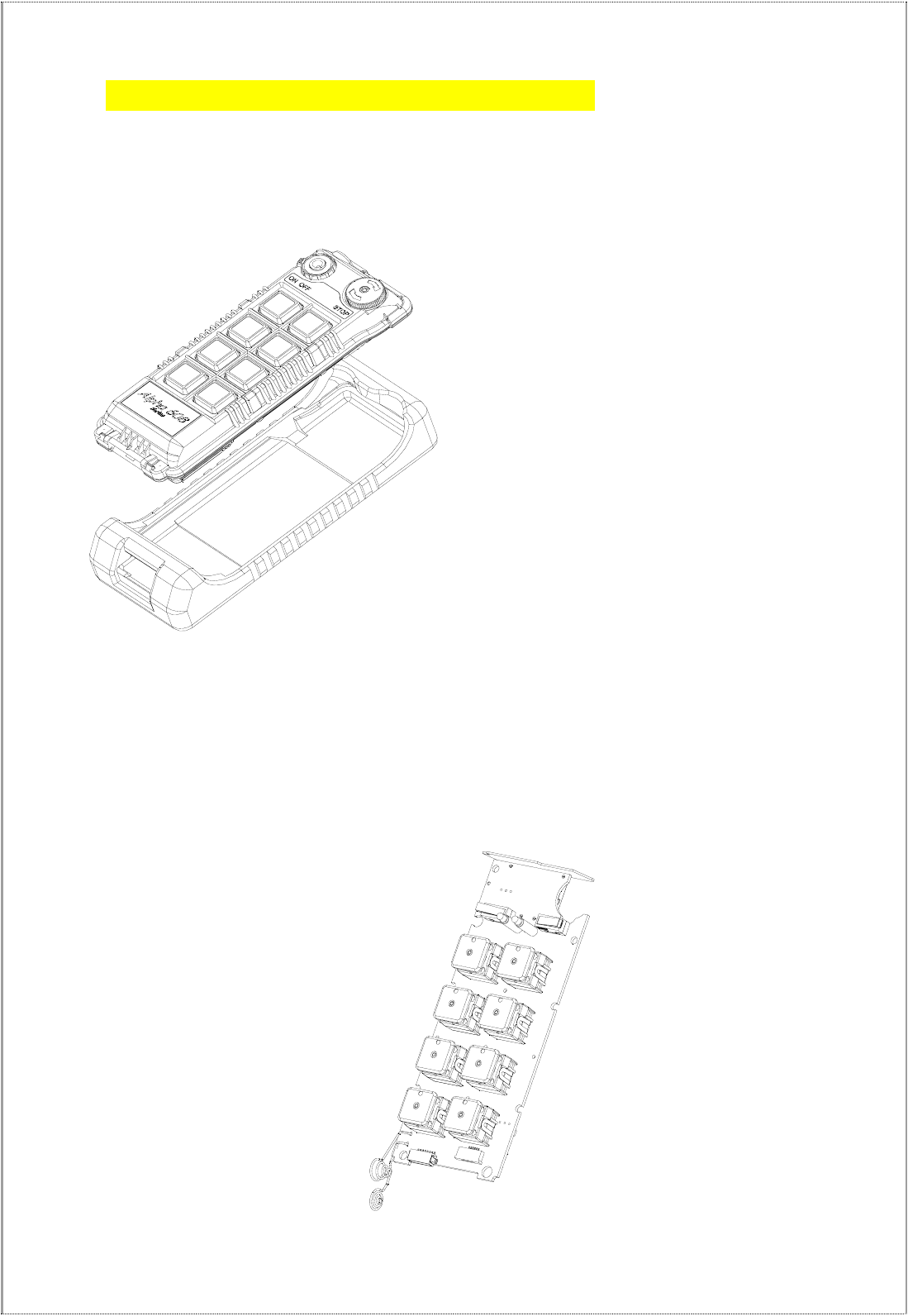
3.1 Transmitter Outline
3.1.1 Alpha 608
3.1.2.1 SIZE: 189mm X 68mm X 30mm
(Fig.1) Transmitter Outline
3.1.2.2 TX INTERNAL MODULE – encoder board
(Fig.4) Encoder board
- 6 -
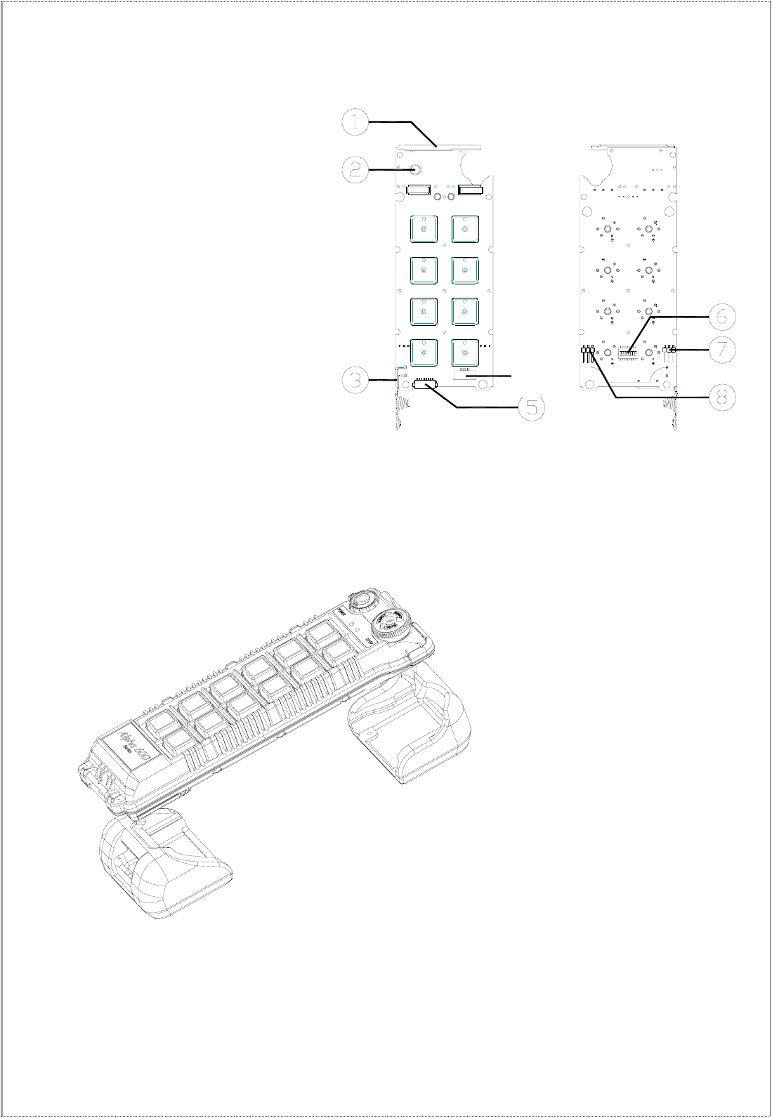
3.1.2.3 TRANSMITTER INTERNAL ASSEMBLY
(1) Internal antenna
(2) Status LED display
(3) Battery contact
(5) Programming port
(6) ID code dip-switch
(7) JP2 setting pin
(8) JP1 setting pin
(Fig.2) Front View (Fig.3) Back View
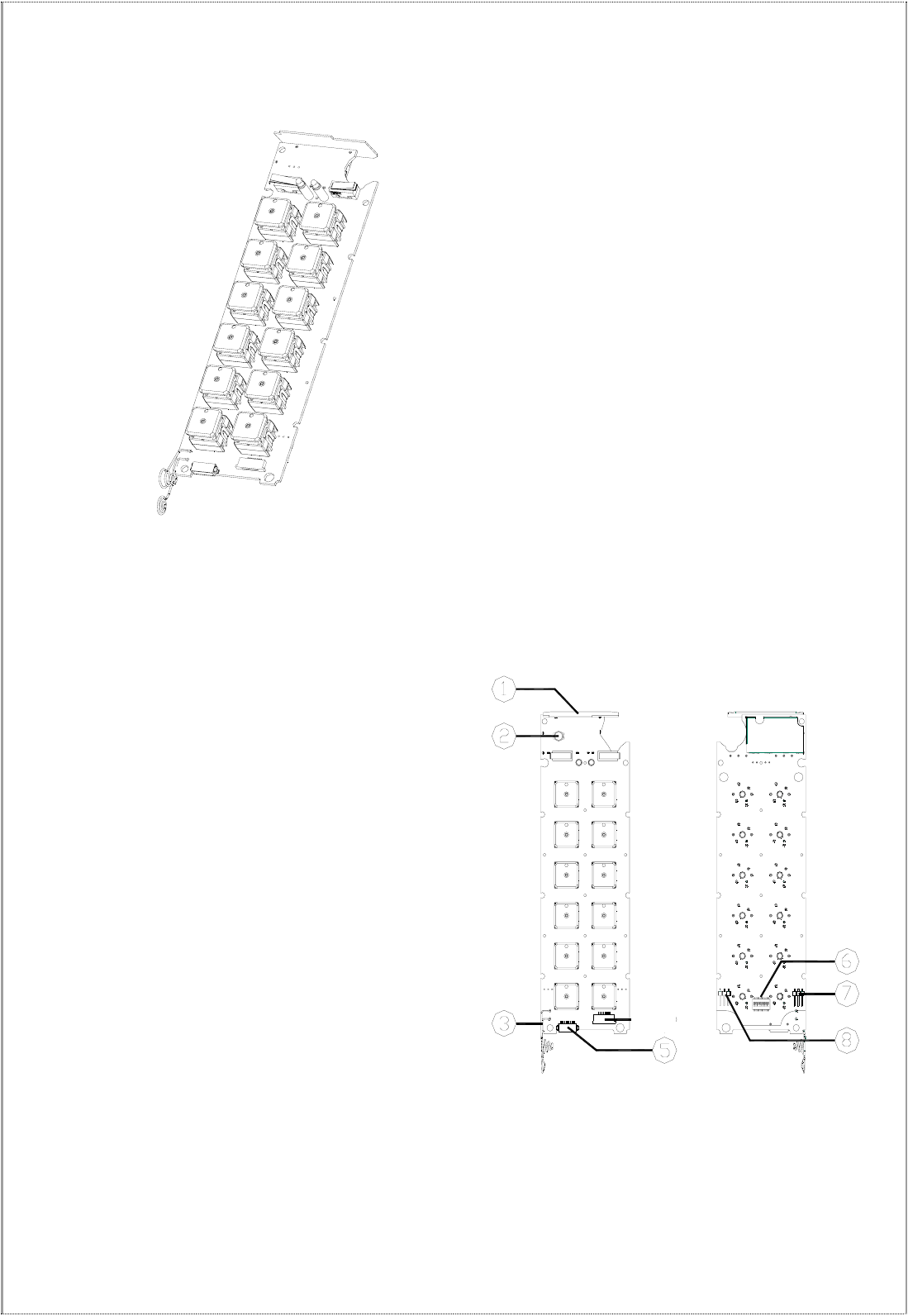
3.1.3 Alpha 612
3.1.3.1 SIZE: 235mm X 68mm X 30mm
(Fig.1) Transmitter Outline
- 7 -
3.1.3.2 TX INTERNAL MODULE
Encoder Board
3.1.3.3 TRANSMITTER INTERNAL ASSEMBLY
(1) Internal antenna
(2) Status LED display
(3) Battery contact
(5) Programming port
(6) ID code dip-switch
(7) JP2 setting pin
(8) JP1 setting pin
(Fig.2) Front View (Fig.3) Back View
- 8 -
3.2 Alpha 604/607/608/612 Spare Parts
4
4.
.
R
RE
EC
CE
EI
IV
VE
ER
R
O
OU
UT
TL
LI
IN
NE
E
4
4.
.1
1
A
Al
lp
ph
ha
a
6
60
07
7/
/6
60
08
8
4
4.
.1
1.
.1
1
E
Ex
xt
te
er
rn
na
al
l
A
As
ss
se
em
mb
bl
ly
y
SIZE:310mm X 134mm X 72mm
AC
SQ
M
A
W
S
N
E
U
D
AC
SQ
M
A
S/ N:
FREQ:
MOD:
VOLT:
CH.
ID:
FILTER
Anti-vibration spring
must be grounded
POWER
MAIN
F6
5A
F1
F5 5A
LV/AUX1
COM417
L2(X2)
L1(X1)
GRN/YEL
COM5
MAIN
22
FF1
21
20
18
19
AUX1
AUX2
NC
COM3
NC
COM2
15
16
14 LV
N1
S1
COM1
D1
W1
E1
NC
NC
U1
F4 5A
F3 5A
13
10
11
12
9
8
3
5
6
7
4
F2 5A
2
1
BRIDGE
TROLLEY
HOIST
/AUX2
(Fig.7) Front View (Fig.8) Back View
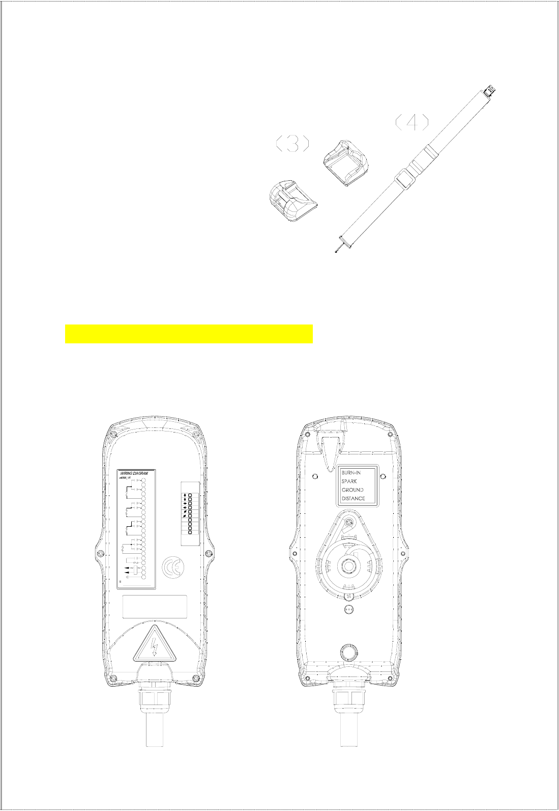
(3) Transmitter shock-absorbing rubber
(4) Shoulder strap
- 9 -
4
4.
.1
1.
.2
2
A
Al
lp
ph
ha
a
6
60
08
8
I
In
nt
te
er
rn
na
al
l
A
As
ss
se
em
mb
bl
ly
y
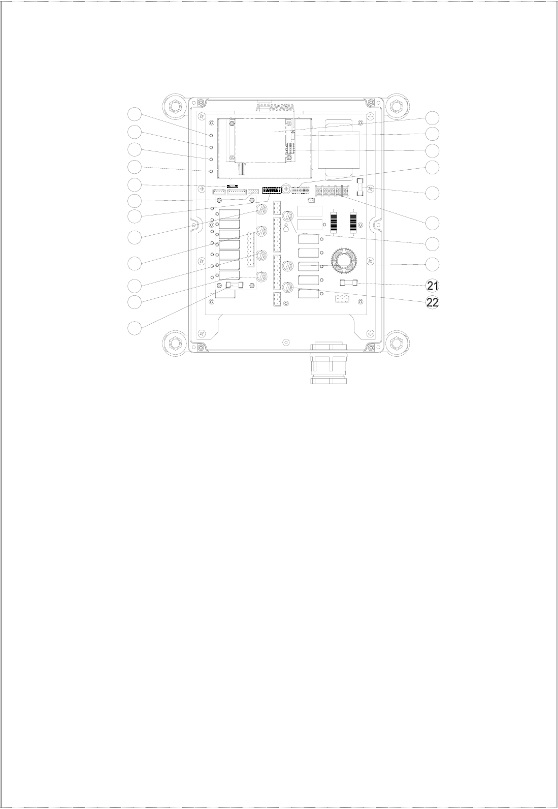
(Fig. 9) Internal Parts Assembly
1) Receiving RF module
2) External programming port
3) Secondary power AC fuse (0.50A)
4) Contact output seat (CN8)
5) Primary power AC fuse (1.0A)
6) AC power input seat (CN2)
7) Internal Antenna
8) System Status LED display*
9) External antenna port
10) ID code dip-switch
11) RF channel dip-switch
12) Contact relay LED display
13) Pushbutton #1and #2 fuse (5.0A)
14) Contact output seat (CN3)
15) MAIN contact fuse (5.0A)
16) Pushbutton #3 and #4 fuse (5.0A)
17) Pushbutton #5 and #6 fuse (5.0A)
18) Contact output seat (CN4)
19) LV & AUX fuse (5.0A)
20) Cable gland & output cable
* Please refer to page 27 for system status
LED display information.
FUSE
FUSE
FUSE
1
2
8
4
11
10
12
13
14
15
17
18
9
16
20
FUSE
FUSE
FUSE
3
5
6
7
19
- 10 -
4
4.
.2
2
A
Al
lp
ph
ha
a
6
61
12
2
4
4.
.2
2.
.1
1
E
Ex
xt
te
er
rn
na
al
l
A
As
ss
se
em
mb
bl
ly
y
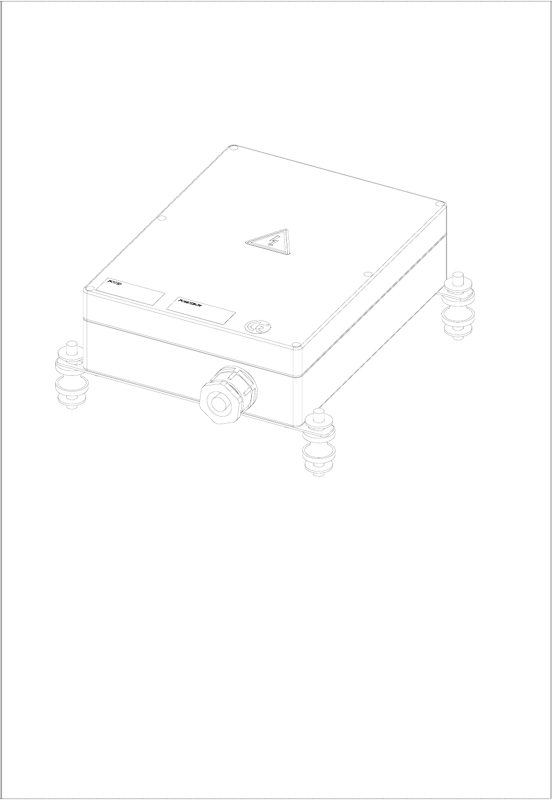
SIZE:300mm X 230mm X 86mm
(Fig. 17) External Parts Assembly
1) Transparent top cover 3) Mounting bracket with shock absorbers
2) Light-gray colored base 4) Cable gland / Cord grip
- 11 -
17
20
19
18
16
14
5
10
11
9
7
8
6
1
3
4
213
15
12
4
4.
.2
2.
.2
2
A
Al
lp
ph
ha
a
6
61
12
2
I
In
nt
te
er
rn
na
al
l
A
As
ss
se
em
mb
bl
ly
y
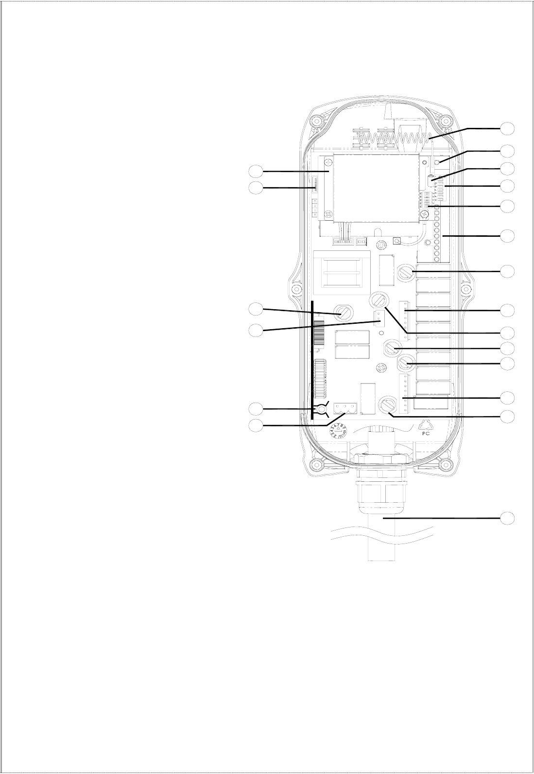
(Fig. 18) Internal Parts Assembly
1) Power LED display* 12) Pushbutton #1 and #2 relay fuse (5.0A)
2) SQ LED display** 13) Receiving RF module
3) Status LED display**** 14) External antenna port
4) DC power relay LED display*** 15) RF channel dip-switch
5) Programming port 16) ID code dip-switch
6) Jumper settings 17) Secondary power fuse (0.8A)
7) Function dip-switch 18) Voltage selector seat
8) Pushbutton #3 and #4 relay fuse (5.0A) 19) MAIN relay fuse (5.0A)
9) Pushbutton #5 and #6 relay fuse (5.0A) 20) Pushbutton A4 relay fuse (5.0A)
10) Pushbutton A1and A2 relay fuse (5.0A) 21) Primary power fuse (1.0A)
11) Pushbutton A3 relay fuse (5.0A) 22) Low-voltage (LV) relay fuse (5.0A)
* POWER ~ AC Power Source Indicator "on" → AC input power supplied.
"off" → No AC input power.
** SQ ~ RF Signal Indicator "on" → RF signal detected and received.
"off" → No RF signal detected or received.
Blinking at transmitter power “off” → Other radio interference.
*** RELAY_COM ~ DC Power Source to Relays "on" → DC power to relays.
"off" → No DC power to relays.
**** STATUS ~ Receiver System Status LED Display → Please refer to page 32.
- 12 -
5
5.
.
O
OU
UT
TP
PU
UT
T
C
CO
ON
NT
TA
AC
CT
T
D
DI
IA
AG
GR
RA
AM
MS
S
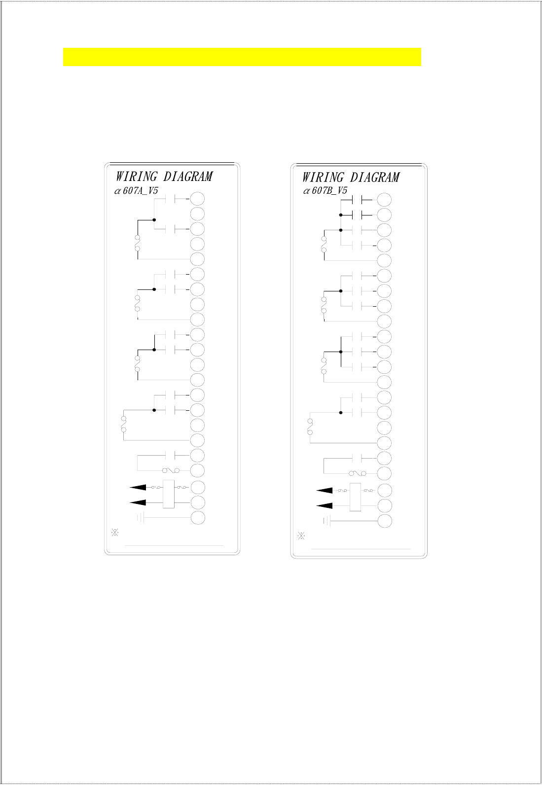
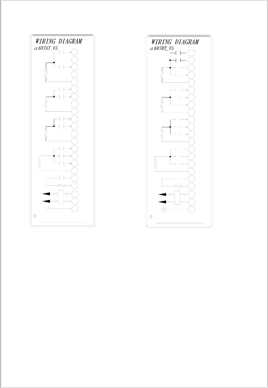
5
5.
.1
1
A
Al
lp
ph
ha
a
6
60
07
7
M
Mo
od
de
el
ls
s
(
(Alpha 607A) (Alpha 607B)
FILTER
Anti-vibration spring
must be grounded
POWER
MAIN
F6
5A
F1
F5 5A
LV/AUX1
COM4
17
L2(X2)
L1(X1)
GRN/YEL
COM5
MAIN
22
FF1
21
20
18
19
AUX1
NC
NC
COM3
NC
COM2
15
16
14 LV
N1
S1
COM1
D1
W1
E1
NC
NC
U1
F4 5A
F3 5A
13
10
11
12
9
8
3
5
6
7
4
F2 5A
2
1
BRIDGE
TROLLEY
HOIST
FILTER
Anti-vibration spring
must be grounded
POWER
MAIN
F6
5A
F1
F5 5A
LV/AUX1
BRIDGE
F4 5A
TROLLEY
F3 5A
COM4
17
L2(X2)
L1(X1)
GRN/YEL
COM5
MAIN
22
FF1
21
20
18
19
AUX1
NC
N/S2
COM3
E/W2
COM2
15
16
14
13 LV
N1
10
11
12 S1
9
8
COM1
D1
3
5
6
7W1
E1
4D2
HOIST
F2 5A 2
1U2
U1
- 13 -
FILTER
Anti-vibration spring
must be grounded
POWER
MAIN
F6
5A
F1
F5 5A
LV/SEL-I
COM4
17
L2(X2)
L1(X1)
GRN/YEL
COM5
MAIN
22
FF1
21
20
18
19
SEL-I
SEL-II
NC
COM3
NC
COM2
15
16
14 LV
N1
S1
COM1
D1
W1
E1
NC
NC
U1
F4 5A
F3 5A
13
10
11
12
9
8
3
5
6
7
4
F2 5A
2
1
BRIDGE
TROLLEY
HOIST
/SEL-II
(
(Alpha 607AT) (Alpha 607BT)
FILTER
Anti-vibration spring
must be grounded
POWER
MAIN
F6
5A
F1
F5 5A
LV/SEL-I
BRIDGE
F4 5A
TROLLEY
F3 5A
COM4
17
L2(X2)
L1(X1)
GRN/YEL
COM5
MAIN
22
FF1
21
20
18
19
SEL-I
SEL-II
N/S2
COM3
E/W2
COM2
15
16
14
13 LV
N1
10
11
12 S1
9
8
COM1
D1
3
5
6
7W1
E1
4D2
HOIST
F2 5A 2
1U2
U1
/SEL-II
- 14 -
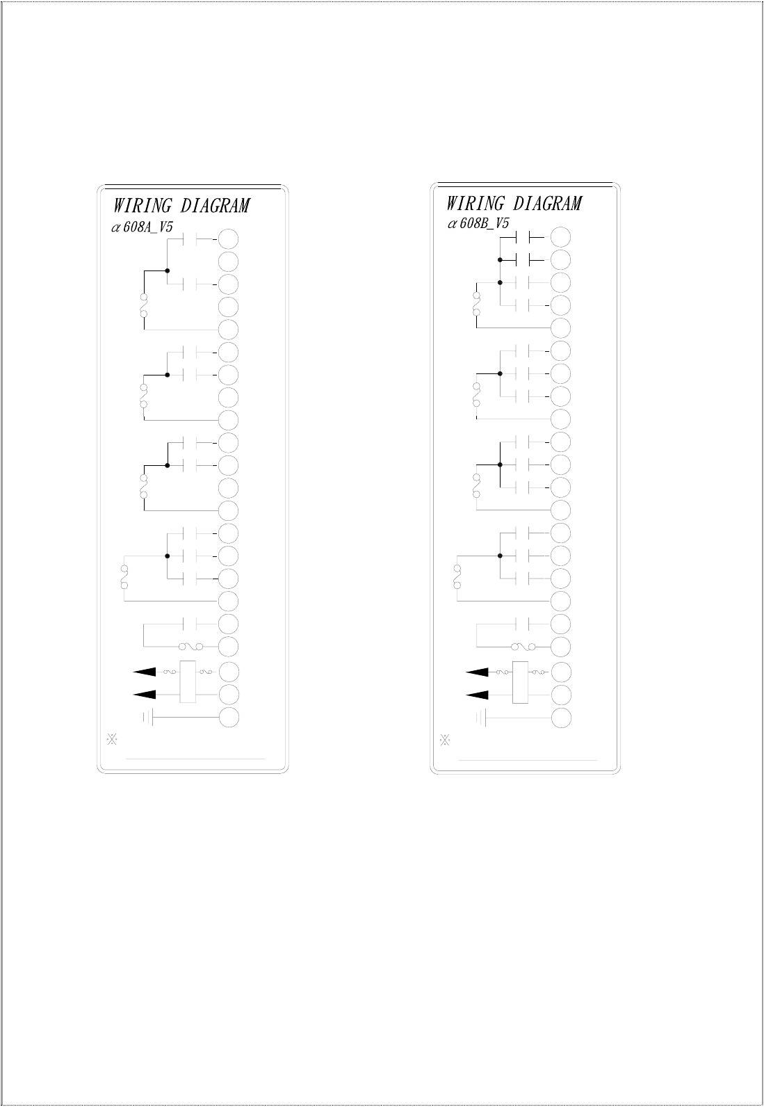
5
5.
.2
2
A
Al
lp
ph
ha
a
6
60
08
8
M
Mo
od
de
el
ls
s
(
(Alpha 608A) (Alpha 608B)
FILTER
Anti-vibration spring
must be grounded
POWER
MAIN
F6
5A
F1
F5 5A
LV/AUX1
COM4
17
L2(X2)
L1(X1)
GRN/YEL
COM5
MAIN
22
FF1
21
20
18
19
AUX1
AUX2
NC
COM3
NC
COM2
15
16
14 LV
N1
S1
COM1
D1
W1
E1
NC
NC
U1
F4 5A
F3 5A
13
10
11
12
9
8
3
5
6
7
4
F2 5A
2
1
BRIDGE
TROLLEY
HOIST
/AUX2
FILTER
Anti-vibration spring
must be grounded
POWER
MAIN
F6
5A
F1
F5 5A
LV/AUX1
BRIDGE
F4 5A
TROLLEY
F3 5A
COM4
17
L2(X2)
L1(X1)
GRN/YEL
COM5
MAIN
22
FF1
21
20
18
19
AUX1
AUX2
N/S2
COM3
E/W2
COM2
15
16
14
13 LV
N1
10
11
12 S1
9
8
COM1
D1
3
5
6
7W1
E1
4D2
HOIST
F2 5A 2
1U2
U1
/AUX2
- 15 -
5
5.
.3
3
A
Al
lp
ph
ha
a
6
61
12
2
M
Mo
od
de
el
ls
s
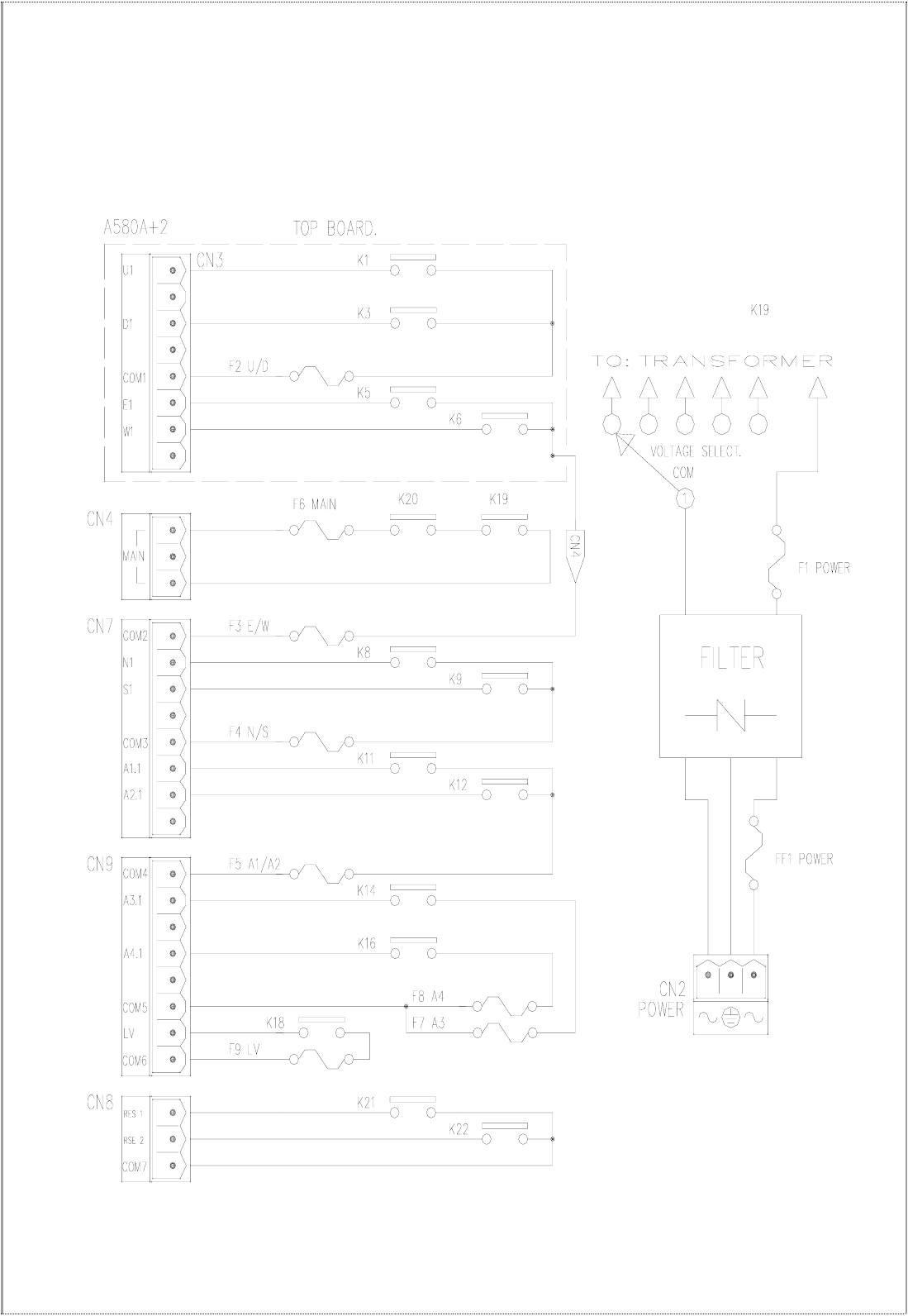
(Alpha 612A) – same as Alpha 580A+2
- 16 -
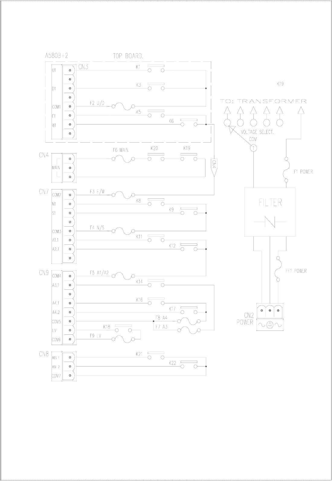
(Alpha 612B) – same as Alpha 580B+2
- 17 -
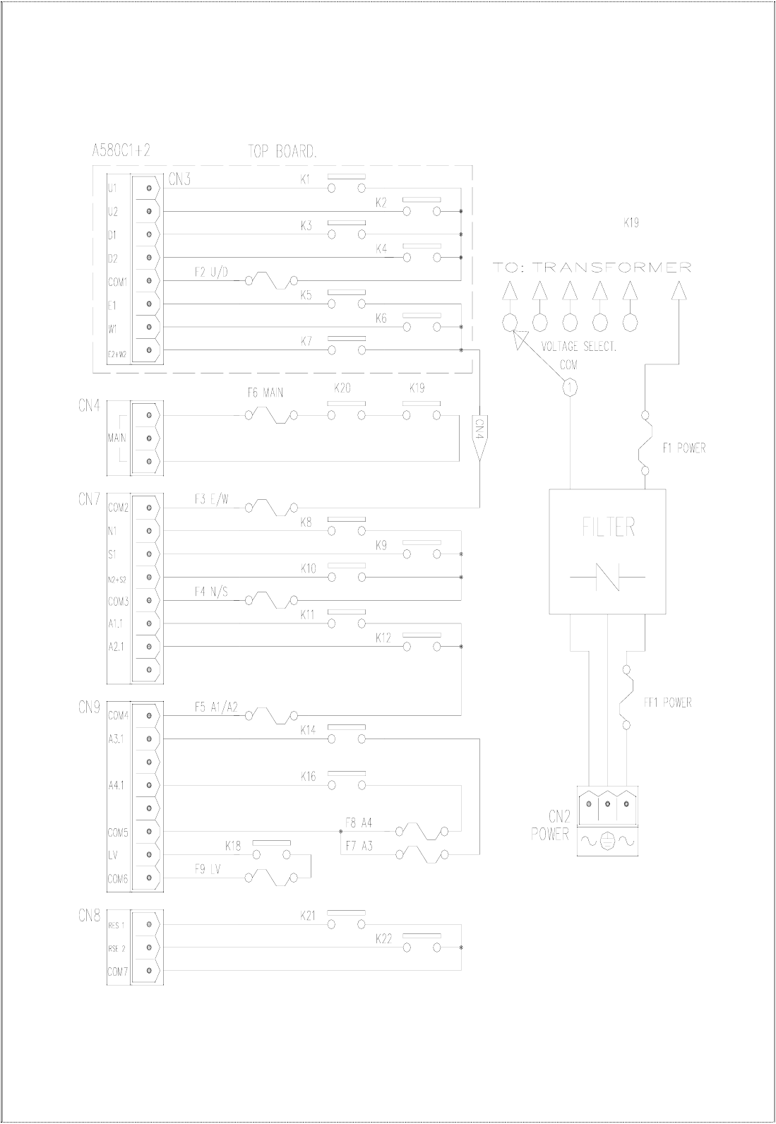
(Alpha 612C-1) – same as Alpha 580C-1+2
- 18 -
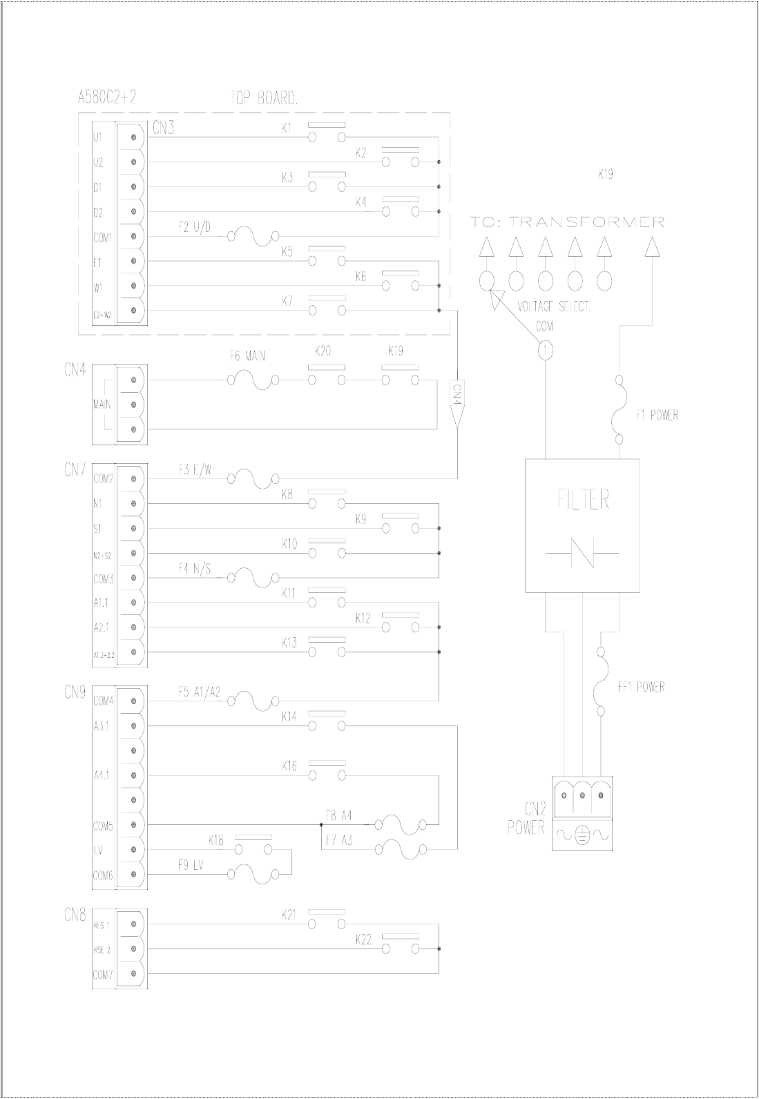
(Alpha 612C-2) – same as Alpha 580C-2+2
- 19 -
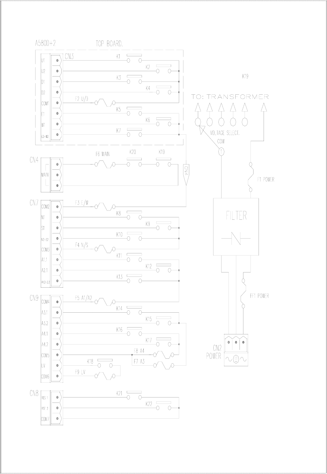
(Alpha 612D) – same as Alpha 580D+2
- 20 -
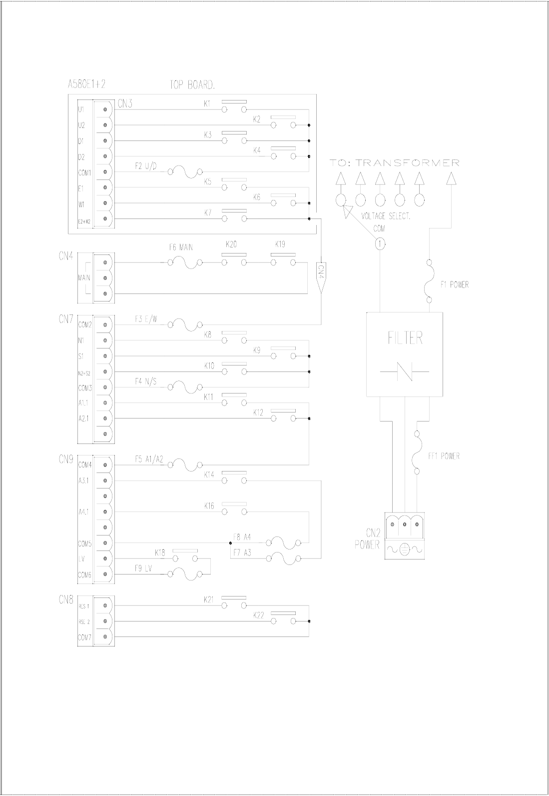
(Alpha 612E-1) – same as Alpha 580E-1+2
- 21 -
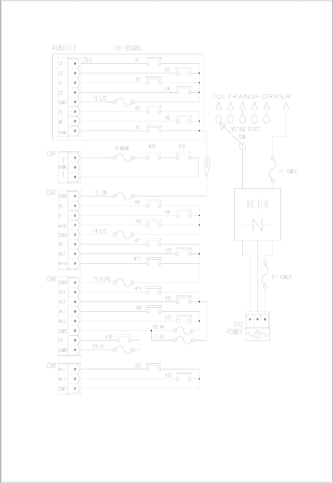
(Alpha 612E-2) – same as Alpha 580E-2+2
- 22 -
6
6.
.
T
TR
RA
AN
NS
SM
MI
IT
TT
TE
ER
R
S
SE
ET
TT
TI
IN
NG
GS
S
6
6.
.1
1
H
Ho
ow
w
t
to
o
S
Se
et
t
I
ID
D
C
Co
od
de
es
s
6.1.1 Set by programming tool
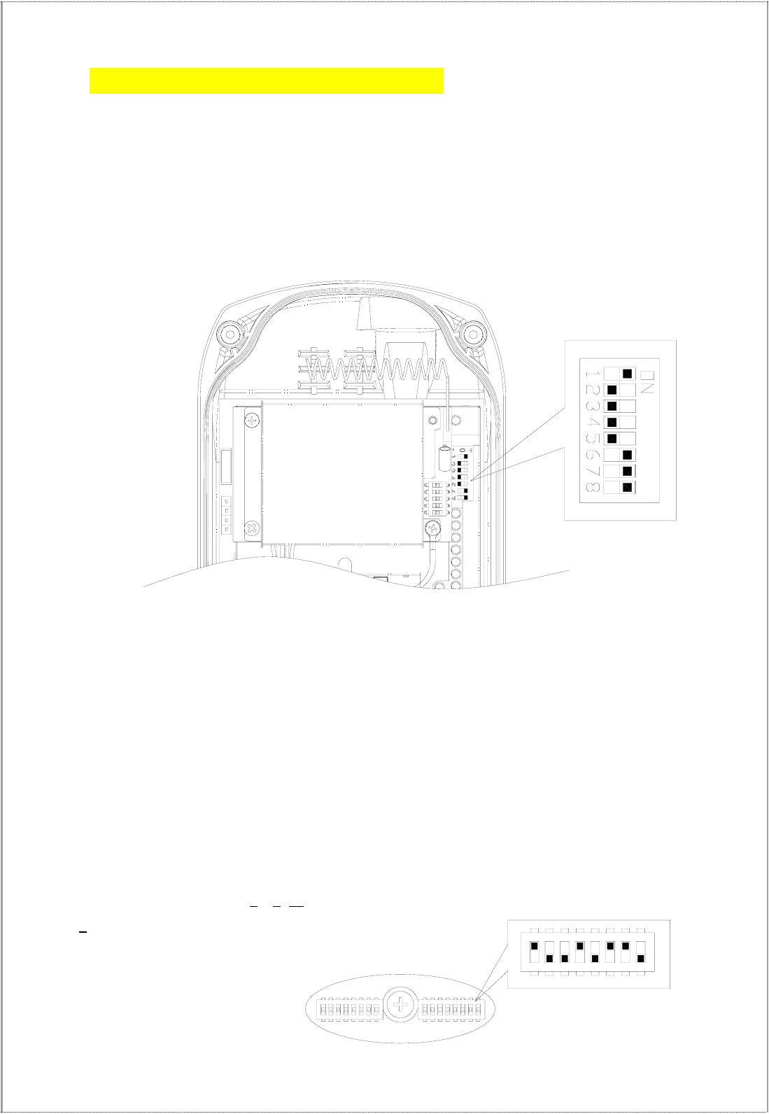
6.1.2 Set by encoder board JP1, 1st / 2nd pin and dip-switch
Setting Steps:
(1) Rotate the transmitter power to OFF position
(2) Disassemble shock-absorbing rubber
(3) Put the transmitter pushbutton downward and disassemble transmitter bottom casing.
(4) Set ID code with dip-switch and put short boot on 1st / 2nd pin of JP1.
(5) Make sure the batteries are installed properly.
(6) Rotate the transmitter power switch to ON position.
(7) Green status LED ON for 0.1 sec, OFF for 0.1 sec, flash for 1 sec. (5 times)
(8) Green status LED steady ON indicates the setting is completed. If the LED status light is changed to red,
the setting is failed. Please repeat the above setting steps until the setting is successful.
(9) After setting is completed and successful, remove short boot on 1, 2 pin of JP1.
(10) Rotate transmitter power switch to OFF position.
編碼板
(Fig. 10) Back view (Fig. 11) Position of dip-switch & jumpers
Top slot ON Æ “1”; bottom slot Æ “0”. The setting above is 00000011.

- 23 -
6
6.
.2
2
T
Tr
ra
an
ns
sm
mi
it
tt
te
er
r
C
Ch
ha
an
nn
ne
el
l
S
Se
et
tt
ti
in
ng
gs
s
Transmitter channel setting (select the channel you would like to operate. No exceed to
channel limit)
6.2.1 Set by programming tool
6.2.2 Set by encoder board 2nd & 3rd pin of JP1 and dip-switch
When setting frequency on TX board JP1, put short boot on 2nd & 3rd pin of JP1. Change the frequency
needed by changing the dip-switch setting. Repeat the previous steps to set frequency.
(Note: set the dip-switch from the 4th digit)
Example:Set channel as 03→(00000011) → Correct setting
- 24 -
7
7.
.
R
RE
EC
CE
EI
IV
VE
ER
R
S
SE
ET
TT
TI
IN
NG
GS
S
7
7.
.1
1
H
Ho
ow
w
t
to
o
S
Se
et
t
6
60
07
7/
/6
60
08
8/
/6
61
12
2
R
Re
ec
ce
ei
iv
ve
er
r
I
ID
D
C
Co
od
de
es
s
7
7.
.1
1.
.1
1
H
Ho
ow
w
t
to
o
S
Se
et
t
6
60
07
7/
/6
60
08
8
R
Re
ec
ce
ei
iv
ve
er
r
I
ID
D
C
Co
od
de
e
Top slot Æ “1”
Bottom slot Æ “0”
ID DIP-SW
Set the ID codes needed on the decoder board dip-switch. For example: the ID codes set above Æ
10000111.
7
7.
.1
1.
.2
2
H
Ho
ow
w
t
to
o
s
se
et
t
α
α6
61
12
2
R
Re
ec
ce
ei
iv
ve
er
r
I
ID
D
C
Co
od
de
e
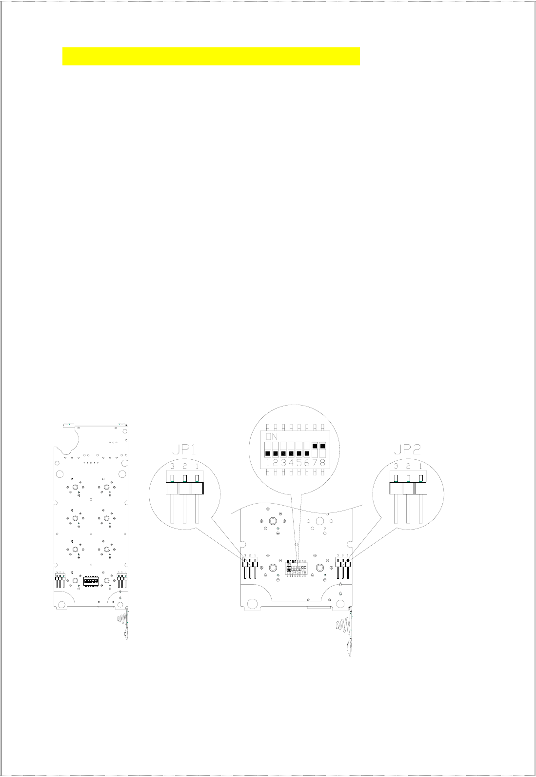
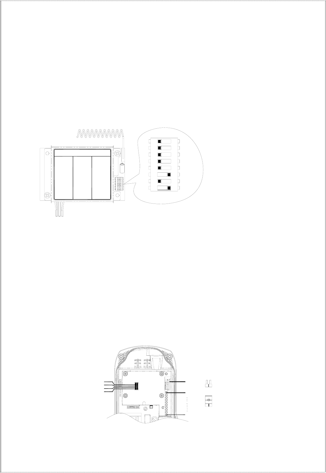
Please refer Fig. 18 receiver internal parts assembly (Page 17) for ID code 8-position dip-switch to set receiver ID
code.
Top slo t Æ“1"; bottom slot Æ“0"
Set the ID codes needed on the decoder board dip-switch.
For example: the ID codes → 1
0010110
(“1” value adds up must to be “4”)
12345678
- 25 -
FUSE
JP1 OPEN→JUMP
SHORT→JUMP
AC
DIP-SW
U
JP3
JP2
JP4
7.2 Receiver RF Channel Setting
There are 68 sets of user-adjustable receiving RF channels that can be set manually via a 8-position dip-switch
located to the right of the receiving RF module. Change the receiving RF channel simply by resetting these
8-position dip-switch. For the location of the receiving RF module, please refer to fig. 15, 16, and 18 on page 11,
12, and 14.
Top slot Æ“1"; bottom slot Æ“0"
For example:the channel dip-switch set above Æ 00000101, channel 05.
7.3 Receiver Function Setting
7.3.1 607/608 Receiver Function Setting
7.3.1.1 Set by programming tool
7.3.1.2. Adjust Jumper setting function by decoder board
Receiver function setting:
A. Select any pushbutton or ON/OFF power switch to start the system. The MAIN relay will be activated
when system is started. (After the receiver power is started and emergency stop button is elevated)
B. The MAIN relay auto shutdown time can be set as 3 minutes or depends on customer’s single request.
(Remark 1)
C. When transmitter voltage is low, relays for the receiver MAIN and LV (Remark 1) will be auto shutdown after
one minute.
(Fig. 12) Alpha 607, 608 models
12 436587
Channel → Dip-Switch Settings
Part Number:BRXN-433
CH.401→ 00000001 CH.424→ 00011000 CH.447→ 00101111
CH.402→ 00000010 CH.425→ 00011001 CH.448→ 00110000
CH.403→ 00000011 CH.426→ 00011010 CH.449→ 00110001
CH.404→ 00000100 CH.427→ 00011011 CH.450→ 00110010
CH.405→ 00000101 CH.428→ 00011100 CH.451→ 00110011
CH.406→ 00000110 CH.429→ 00011101 CH.452→ 00110100
CH.407→ 00000111 CH.430→ 00011110 CH.453→ 00110101
CH.408→ 00001000 CH.431→ 00011111 CH.454→ 00110110
CH.409→ 00001001 CH.432→ 00100000 CH.455→ 00110111
CH.410→ 00001010 CH.433→ 00100001 CH.456→ 00111000
CH.411→ 00001011 CH.434→ 00100010 CH.457→ 00111001
CH.412→ 00001100 CH.435→ 00100011 CH.458→ 00111010
CH.413→ 00001101 CH.436→ 00100100 CH.459→ 00111011
CH.414→ 00001110 CH.437→ 00100101 CH.460→ 00111100
CH.415→ 00001111 CH.438→ 00100110 CH.461→ 00111101
CH.416→ 00010000 CH.439→ 00100111 CH.462→ 00111110
CH.417→ 00010001 CH.440→ 00101000 CH.463→ 00111111
CH.418→ 00010010 CH.441→ 00101001 CH.464→ 01000000
CH.419→ 00010011 CH.442→ 00101010 CH.465→ 01000001
CH.420→ 00010100 CH.443→ 00101011 CH.466→ 01000010
CH.421→ 00010101 CH.444→ 00101100 CH.467→ 01000011
CH.422→ 00010110 CH.445→ 00101101 CH.468→ 01000100
CH.423→ 00010111 CH.446→ 00101110
- 26 -
Jumper Set table: in-plant setting (default).
JP1 Open
Power key to activate relay MAIN relay (After turning
“on” the transmitter power and pressing the emergency
Stop button)
Open No auto shutdown time on Main relay
JP2 Short The receiver MAIN will be deactivated after consecutive
5 minutes of standby time.
Open No auto shutdown time on MAIN and LV relays
JP3 Short After one minute of transmitter LV, the MAIN and LV
relays will be deactivated.
Open 7th AUX: “Normal” pushbutton setting
JP4 Short 7th AUX: “Toggle” pushbutton setting
※
Open
→
no Jumper Short
→
put Jumper
Remark 1:The setting of auto shutdown time can be done by manufacturer or distributor. Setting range: 0~30
minutes. (In-plant setting: 5 minutes)
Remark 2:When the transmitter voltage is low, LV relay will be activated and siren or lights will be ON. (one
second of interval)
Remark 3:Every time when you change jumper settings you must first turn the receiver power off and then turn
it back on so that the new settings can be stored in memory.
7.3.2 α612 Receiver Function Setting
7.3.2.1 Set by programming tool
7.3.2.2. Adjust Jumper setting function by decoder board
R
Re
ec
ce
ei
iv
ve
er
r
f
fu
un
nc
ct
ti
io
on
n
s
se
et
tt
ti
in
ng
g:
:
Jumper Set table: In-plant setting (default).
JP1 Open
Power key to activate relay MAIN relay (After turning
“on” the transmitter power and pressing the
emergency stop button)
Open No auto shutdown time on Main relay
JP2 Short The receiver MAIN will be deactivated after
consecutive 5 minutes of standby time.
Open No auto shutdown time on MAIN and LV relays
JP3 Short After one minute of transmitter LV, the MAIN and LV
relays will be deactivated.
※
Open
→
No jumper Short
→
Put Jumper
Remark 1:The setting of auto shutdown time can be done by manufacturer or distributor. Setting range: 0~30
minutes. (In-plant setting: 5 minutes)
Remark 2:When the transmitter voltage is low, LV relay will be activated and siren or lights will be ON. (One
second of interval)
Remark 3:Every time when you change jumper settings you must first turn the receiver power off and then turn
it back on so that the new settings can be stored in memory.

- 27 -
7.3.3 Alpha 612 Models Dip-Switch Function Table
Model Pushbutton Dip-Switch Setting Description
→ 1 Not Interlocked
1 & 2
3 & 4
5 & 6
DIP 1
→ 0 Interlocked
→ 1 Not Interlocked
7 & 8 DIP 2
→ 0 Interlocked
→ 1 Latching/toggle relay contact
7 & 8 DIP 3
→ 0 Momentary relay contact
DIP2 Set at “1”
→ 1 Not Interlocked
612A
9 & 10 DIP 4
→ 0 Interlocked
→ 1 Latching/toggle relay contact
9 DIP 5
→ 0 Momentary relay contact
DIP4 Set at “1”
→ 1 Latching/toggle relay contact
612B
10 DIP 6
→ 0 Momentary relay contact
DIP4 Set at “1”
→ 1 Not Interlocked
7 & 8 DIP 1
→ 0 Interlocked
→ 1 Latching/toggle relay contact
7 DIP 2
→ 0 Momentary relay contact DIP4 Set at “1”
→ 1 Latching/toggle relay contact
8 DIP 3
→ 0 Momentary relay contact
DIP4 Set at “1”
→ 1 Latching/toggle relay contact
612B
9 DIP 4
→ 0 Momentary relay contact
→ 1
Both 1st and 2nd speed contact
relay interlocked when pressed
to 2nd speed
Both 1st and 2nd speed
contact relays activated
612C
1 & 2
(2nd speed) DIP 1
→ 0
Both 1st and 2nd speed contact
relay activated when pressed to
2nd speed
Only 2nd speed contact
relay activated

- 28 -
DIP 2,3 → 00 Momentary relay contact
DIP 2,3 → 01 Latching/toggle relay contact
9
DIP 2,3 → 10 Activate the 3rd speed
→ 1 Latching/toggle relay contact
10 DIP 4
→ 0 Momentary relay contact
→ 1
Both 1st and 2nd speed contact
relay interlocked when pressed
to 2nd speed
Both 1st and 2nd speed
contact relays activated
1 & 2
(2nd speed) DIP 1
→ 0
Both 1st and 2nd speed contact
relay activated when pressed to
2nd speed
Only 2nd speed contact
relay activated
612D
--- DIP 2,3,4 →0 Momentary relay contact
DIP2&3 Must set to
“0” all the time
(In-plant set at “0”)
→ 1
Both 1st and 2nd speed contact
relay interlocked when pressed
to 2nd speed
Both 1st and 2nd speed
contact relays activated
1 & 2
(2nd speed) DIP 1
→ 0
Both 1st and 2nd speed contact
relay activated when pressed to
2nd speed
Only 2nd speed contact
relay activated
→ 1 Not Interlocked
7 & 8 DIP 2
→ 0 Interlocked
→ 1 Latching/toggle relay contact
612E
7 DIP 3
→ 0 Momentary relay contact
DIP2 Set at “1”
→ 1 Latching/toggle relay contact
11 DIP 7
→ 0 Momentary relay contact
→ 1 Latching/toggle relay contact
612
A/B/C/D/E
12 DIP 8
→ 0 Momentary relay contact
※
※
In-plant all set at “0”

- 29 -
7
7.
.4
4
F
Fr
re
eq
qu
ue
en
nc
cy
y
(
(R
RF
F)
)
C
Ch
ha
an
nn
ne
el
ls
s
T
Ta
ab
bl
le
e
FREQUENCY DIP-SWITCH SETTING CHANNEL
433.075 MHz 00000001 01
433.100 MHz 00000010 02
433.125 MHz 00000011 03
433.150 MHz 00000100 04
433.175 MHz 00000101 05
433.200 MHz 00000110 06
433.225 MHz 00000111 07
433.250 MHz 00001000 08
433.275 MHz 00001001 09
433.300 MHz 00001010 10
433.825 MHz 00001011 11
433.850 MHz 00001100 12
433.875 MHz 00001101 13
433.900 MHz 00001110 14
433.925 MHz 00001111 15
433.950 MHz 00010000 16
433.975 MHz 00010001 17
434.000 MHz 00010010 18
434.025 MHz 00010011 19
434.050 MHz 00010100 20
434.075 MHz 00010101 21
434.100 MHz 00010110 22
434.125 MHz 00010111 23
434.150 MHz 00011000 24
434.175 MHz 00011001 25
434.200 MHz 00011010 26
434.225 MHz 00011011 27
434.250 MHz 00011100 28
434.275 MHz 00011101 29
434.300 MHz 00011110 30
434.325 MHz 00011111 31
434.350 MHz 00100000 32
434.375 MHz 00100001 33

- 30 -
FREQUENCY DIP-SWITCH SETTING CHANNEL
434.400 MHz 00100010 34
434.425 MHz 00100011 35
434.450 MHz 00100100 36
434.475 MHz 00100101 37
434.500 MHz 00100110 38
434.525 MHz 00100111 39
434.550 MHz 00101000 40
434.575 MHz 00101001 41
434.600 MHz 00101010 42
434.625 MHz 00101011 43
434.650 MHz 00101100 44
434.675 MHz 00101101 45
434.700 MHz 00101110 46
434.725 MHz 00101111 47
434.750 MHz 00110000 48
434.775 MHz 00110001 49
433.325 MHz 00110010 50
433.350 MHz 00110011 51
433.375 MHz 00110100 52
433.400 MHz 00110101 53
433.425 MHz 00110110 54
433.450 MHz 00110111 55
433.475 MHz 00111000 56
433.500 MHz 00111001 57
433.525 MHz 00111010 58
433.550 MHz 00111011 59
433.575 MHz 00111100 60
433.600 MHz 00111101 61
433.625 MHz 00111110 62
433.650 MHz 00111111 63
433.675 MHz 01000000 64
433.700 MHz 01000001 65
433.725 MHz 01000010 66
433.750 MHz 01000011 67
433.775 MHz 01000100 68

- 31 -
8
8.
.
T
TR
RA
AN
NS
SM
MI
IT
TT
TE
ER
R
O
OP
PE
ER
RA
AT
TI
IO
ON
N
&
&
S
ST
TA
AT
TU
US
S
L
LI
IG
GH
HT
T
8.1 Transmitter Operating Steps
1. Make sure the two “AA” NiMH rechargeable batteries are installed correctly. Please note the polarity of
the batteries.
2. Status lights_To operate the transmitter, please rotate the power key on the top-left corner clockwise to
“on” position. The status LED (green and red) will be steady “on” for 2 seconds and then “off”. If the
transmitter Status LED displays a red blinking light that is “on” Æ 0.1 second and “off” Æ 1.9 seconds, or
no light at all, this indicates the transmitter with batteries needs to be recharged.
3. When any function pushbutton is depressed, the transmitter Status LED displays a red blinking light that is
“on”Æ 0.1 second and “off”Æ 1.9 seconds. If the voltage is low, the transmitter Status LED will be
“on”Æ0.1 second and “off”Æ1.9 seconds, this indicates the transmitter with batteries needs to be
recharged. Continuous operation will cause the transmitter battery power exhausting and cannot operate at
all.
4. EMS & Restarting _ In case of an emergency, press down the red emergency stop button (EMS) will
immediately deactivates the transmitter and receiver MAIN relay. The transmitter Status LED will be
blinking “on”Æ0.5 second and “off”Æ0.5 second for 30 seconds (Mode 0). Then turn off the transmitter
power.
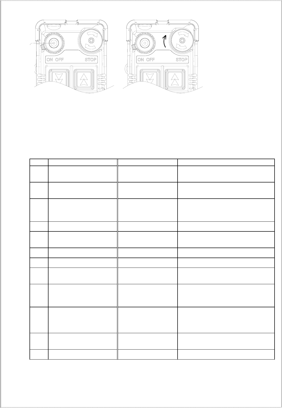
5. The emergency stop button is a right-rotate momentary spring-return type. To turn on the transmitter and
activate the MAIN relay, please elevate the emergency stop button again and rotate the transmitter power
key to “ON” position.
6. Note that the transmitter cannot be hit by outer force, so that malfunction can be prevented.
7. The operating temperature is -10 ~ +50℃. Avoid operating the transmitter in high temperature workshop.
If operating temperature is higher than 50℃,the auto shutdown protection installed inside CPU will shut
down the transmitter and deactivate the MAIN relay.
8. To operation normally, the battery power has to be over 2.2V. If the voltage is lower than 2.2V, the
system cannot be started and low voltage will be showed until the MAIN is completely shutdown.
9. If the power voltage is lowered than 2.2V when transmitter is operated, the LV code will be “1” and low
voltage status light will be shown. The transmitter will stop sending signals when voltage is lower than
2.0V.
- 32 -
STOP: press → lock (emergency stop) STOP: Elevate clockwise → reset (Turn on the transmitter at any time)
8.2 Transmitter Status Light
Type Status Solution LED Indication
1 Charging Place transmitter into
charger Red light ON
2 Power on when voltage is
low BATT<2.2V Red light flash ON_0.1/OFF_1.9 sec
(until power off)
3 Setting failed or invalided
Set data by using
JUMPER & dip-switch
without following rules
Red light ON_0.1/OFF_0.1 sec
4 Setting completed JP1 or JP2 inserted Green light ON until power off.
5 EEPROM ID error EEPROM ID code does
not match CPU Red light ON until power off
6 RF module abnormal PLL UNLOCK Red light ON_0.1/OFF_0.1 sec
7 ID even number error Setting error Red light ON_1/OFF_1 sec
8 Pushbutton locked Power on pushbutton
connected
Red light ON_1.9/OFF_0.1 sec (until
power off)
9 Normal power on
BATT>=2.2V and all the
pushbuttons are not
depressed
All the lights ON_2 sec
10 STOP status STOP button is pressed
MODE 0: Red light ON_0.5/ OFF_
0.5sec, flash 30sec.
MODE 1: all the lights OFF
11 Low voltage during
operation
BATT<2.2V and press
pushbutton Red light flash ON_0.1/OFF_1.9sec
12 Normal operation Press pushbutton Green light flash ON_0.1/OFF_1.9 sec
Power status
light

- 33 -
9
9.
.
R
RE
EC
CE
EI
IV
VE
ER
R
I
IN
NS
ST
TA
AL
LL
LA
AT
TI
IO
ON
N
9
9.
.1
1.
.
P
Pr
re
ep
pa
ar
ra
at
ti
io
on
n
f
fo
or
r
I
In
ns
st
ta
al
ll
la
at
ti
io
on
n
1. Required Tools for Receiver Installation:
(1) Flat Head Screwdriver (-)
(2) Phillips Head Screwdriver (+)
(3) Multi-Meter
(4) 14mm Wrench x 2
(5) Power Drill withφ10.5mm Drill-Bit
2. Check to ensure that your receiver is not set to the same RF channel and ID code as any other systems
in operation at the same facility or within 300-meter distance.
3. Prior to installation, make sure that the crane or equipment itself is working properly.
4. Use a multi-meter to check the voltage source available and ensure the receiver voltage setting
matches your power source.
5. Prior to installation, switch off the main power source to the crane or equipment.
9
9.
.2
2
S
St
te
ep
p
B
By
y
S
St
te
ep
p
I
In
ns
st
ta
al
ll
la
at
ti
io
on
n
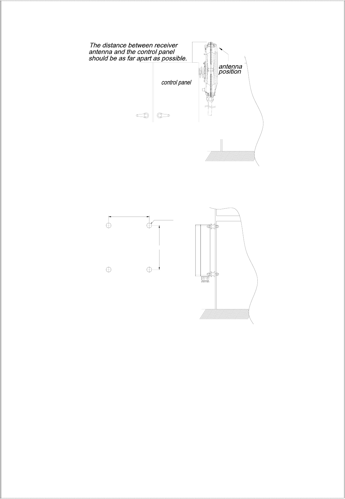
1. For better reception, the location selected should have the antenna visible from all areas where the
transmitter is to be used.
2. The location selected should not be exposed to high levels of electrical noise. Mounting the receiver
next to an unshielded variable frequency control (inverter) may cause minor interference. Always
locate the receiver unit as far away from inverter controls as possible.
3. Ensure the selected location has adequate space to accommodate the receiver enclosure.
4. Make sure the receiver unit is in upright position (vertical).
5. The distance between the antenna and the control panel should be as far apart as possible (refer to the
fig. on page 22).
6. If a crane or equipment’s runway is longer than 100 meters, an external antenna should be added.
The Alpha 608 receiver housing has provisions for an external factory installed antenna available as
an option, contact your dealer for price and delivery.
7. Drill a hole on the control panel (10.5mm).
8. Tightened the bolt nuts provided.
9. If the control panel has a plastic surface, extended grounding wire should be used.
10. For system wiring, please refer to the output contact diagrams from page 4.
11. Ensure all wiring is correct and safely secured and all screws are fastened.
- 34 -
255mm
278mm
4- O10.5
255mm
278mm
4- O10.5
(Fig. 21) Alpha 604, 607, 608 Models
(Fig. 22) Alpha 612 Models
9
9.
.3
3
S
Sy
ys
st
te
em
m
T
Te
es
st
ti
in
ng
g
1. Connect the power source to the receiver and test the MAIN relay output by pressing the red emergency
stop button (EMS) and observe that it properly opens and closes the main line disconnect contactor.
2. Test the operation of each function to ensure it corresponds to the transmitter direction labels and/or the
pendant it is replacing.
3. Test the limit switches on the hoist and/or crane and verify they are working properly.
4. If your new remote control is replacing an existing pendant, make sure it is completely disconnected to
prevent unwanted control commands, i.e. snick circuits.
5. If your new remote control is replacing an existing pendant make sure it is stored in a safe location
where it will not interfere with remote operation (get torn off).
- 35 -
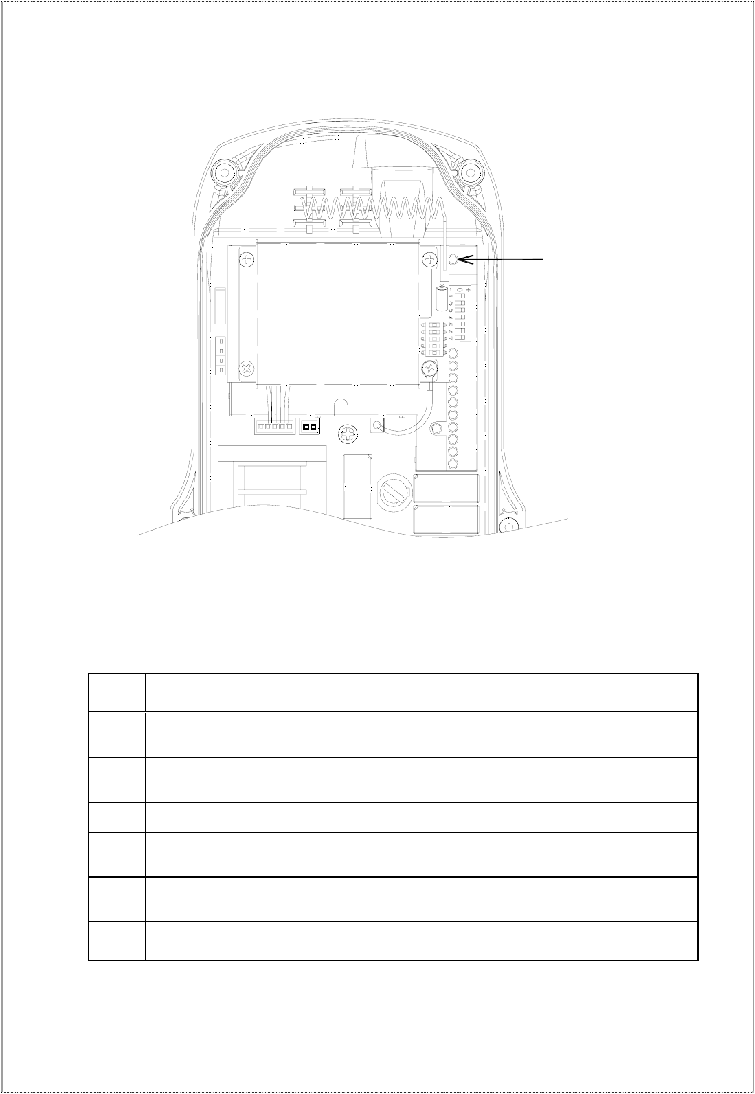
9.4 Receiver system Status LED Display
FUSE
Receiver system Status LED Display
Type Led Indication Problem and Solution
EEPROM error – reprogramming required.
1 Constant red light. Incorrect receiver ID code setting (see note below).
2 ON → 1.0 second
OFF → 1.0 second
ID code not matched on both the transmitter and
receiver unit, please readjust accordingly.
3 Dim or no light. Under-voltage, check the main power-supply.
4 ON → 2.0 seconds
OFF → 0.1 second MAIN contact relay jammed or defective.
5 ON → 0.1 second
OFF → 2.0 seconds
System normal with transmitter pushbutton either in
neutral or in transmitter power “off” position.
6 ON → 0.1 second
OFF → 0.1second
System normal with transmitter pushbutton in
non-neutral position (pushbutton depressed).
Note: Please refer to section 7.2 on page 22 for correct ID code setting.
LED status light

- 36 -
9.4.1 Alpha 612 Receiver System Status LED Display
Led Indication Reason Solution
ON Normal-voltage
Power LED display
OFF Under-voltage
ON Transmitted signals detected
and received
OFF No transmitting signal detected
1.Transmitter standby Turn on the transmitter
SQ, Status LED display
BLINK
2.Interference Turn off the transmitter
ON Normal operation
Relay LED display
OFF Receiver defective Repair decoder board

- 37 -
1
10
0.
.
T
TR
RO
OU
UB
BL
LE
E
S
SH
HO
OO
OT
TI
IN
NG
G
Should the operator find the equipment not operating normally, please check the chart below for simple
trouble shooting tips.
Problem Possible Reason Solution
Transmitter does
not communicate
with the receiver.
Transmitter and the receiver are
not on the same RF channel
(SQ lamp not lit) or ID code.
Ensure the correct transmitter is
in use. The labels on the receiver
and the transmitter will identify the
RF channel and ID code in use.
Transmitter does
not communicate
with the receiver.
Low or no transmitting power
from the transmitter unit.
Turn “on” the transmitter with
EMS elevated. If the status LED
shows blinking red light or no
light at all, then turn the power
“off” and replace the two alkaline
“AA” batteries.
No power to the
receiver (AC power
indicator on the
receiver unit not lit).
Blown fuse or no input power
connection.
Ensure power input to the receiver
unit is correct. If the power
indicator (AC) is still not lit, please
check the receiver for any open fuse.
Outputs do not
operate correctly.
Receiver configuration is not set
properly or output wiring is
incorrect.
Please refer to section 6 and 7
to ensure receiver is correctly wired
and configured for your application.
Transmitter does
not communicate
with the receiver.
Transmitter is turned on with the
EMS activated (pressed down).
Elevate the EMS first and then
turn the power switch off and
then on again.

- 38 -
1
11
1.
.
S
SY
YS
ST
TE
EM
M
S
SP
PE
EC
CI
IF
FI
IC
CA
AT
TI
IO
ON
N
Transmitter Unit
Frequency Range : 433 MHz
Transmitting Range : 100 meters
Hamming Distance : 6
Channel Spacing : 25KHz
Frequency Control : Quartz Crystals
Frequency Drift : < 5ppm @ -25℃ ~ +75℃
Frequency Deviation : < 1ppm @ 25℃
Spurious Emission : - 50dB
Transmitting Power : ~1mW
Emission : F1D
Antenna Impedance : 50 ohms
Enclosure Rating : IP-66
Source Voltage : 3.0V (“AA” alkaline batteries x 2)
Current Drain : 10 ~ 18mA
Operating Temperature : -25℃ ~ +75℃
Dimension (607~608 Models) : 172mm x 68mm x 33mm
(612 Models) : 235mm x 68mm x 30mm
Weight (607~608 Models) : 300g (include batteries)
(612 Models) : 350g (include batteries)
Receiver Unit
Frequency Range : 433 MHz
Channel Spacing : 25KHz
Hamming Distance : 6
Frequency Control : Synthesizer (PLL)
Frequency Drift : < 5ppm @ -25℃ ~ +75℃
Frequency Deviation : < 1ppm @ 25℃
Sensitivity : -120dBm
Antenna Impedance : 50ohms
Data Decoder Reference : Quartz Crystals
Responding Time : 40ms (Normal)
Enclosure Rating : IP-65 (Alpha 500~560 Models)
IP-66 (Alpha 580 Models)
Source Voltage : AC 220V ~ 230V @ 50/60 Hz.
Power Consumption : 11VA
Operating Temperature : -25℃ ~ +75℃
Output Contact Rating : 250V @ 10A
Dimension (607~608 Models) : 310mm x 134mm x 72mm
(612 Models) : 300mm x 236mm x 80mm
Weight (607~608 Models) : 2,000g (include output cable)
(612 Models) : 3,400g (include output cable)

- 39 -
1
12
2.
.
P
PA
AR
RT
TS
S
L
LI
IS
ST
T
Transmitter Part No.
1. Encoder board (Alpha 607A) BEN607A
Encoder board (Alpha 607B) BEN607B
Encoder board (Alpha 607AT) BEN607AT
Encoder board (Alpha 607BT) BEN607BT
Encoder board (Alpha 608A) BEN608A
Encoder board (Alpha 608B) BEN608B
2. Transmitter enclosure (A607 & Alpha 608) BCT607
3. Battery cover BC600
4. 2-step pushbutton B50001
1-step pushbutton B50002
5. Pushbutton rubber fixing holder BCH608
6. Pushbutton rubber boot (Alpha 607 & 608) PRB02
7. Transmitter shock-absorbing rubber (Alpha 607 & 608) SAR02
8. Transmitter vinyl protective cover (Alpha 607 & 608) VPC02
9.EMS pushbutton B50003
10. EMS red cap (all models) EMS01
11. A600 waist strap WS01
12. Rechargeable battery RCB01
13. A600 pushbutton direction label DL01
Receiver
1. Decoder board (Alpha 607A) BDE607A
Decoder board (Alpha 607B) BDE607B
Decoder board (Alpha 607AT) BDE607AT
Decoder board (Alpha 607BT) BDE607BT
Decoder board (Alpha 608A) BDE608A
Decoder board (Alpha 608B) BDE608B
2. 433MHz receiver RF module (All models) BRX433
3. Receiver enclosure (Alpha 607, 608) BCR607
4. Receiver mounting spring (Alpha 607, 608) RMS600
5. Regular Output Contact Relay-blue (All Models) BDE607BT
6. Safety MAIN Contact Relay-DC12V (All Models) BDE608A
7. Transformer (12/24VDC – Alpha 600-608) T24VDC
Transformer (24VAC – Alpha 600-608) T24VAC
Transformer (48VAC – Alpha 600-608) T48VAC
Transformer (110/120VAC – Alpha 600-608) T120VAC
Transformer (220/230VAC – Alpha 600-608) T230VAC
Transformer (380VAC – Alpha 600-608) T380VAC
Transformer (220/230VAC – Alpha 600-608) T230VAC
8. 2-meter Output Cable with 5 Common Circuits Cable (24C*2m V3.5, Alpha 607, 608) OC607
9. Optional External 433 MHz Antenna (All Models) ANT433