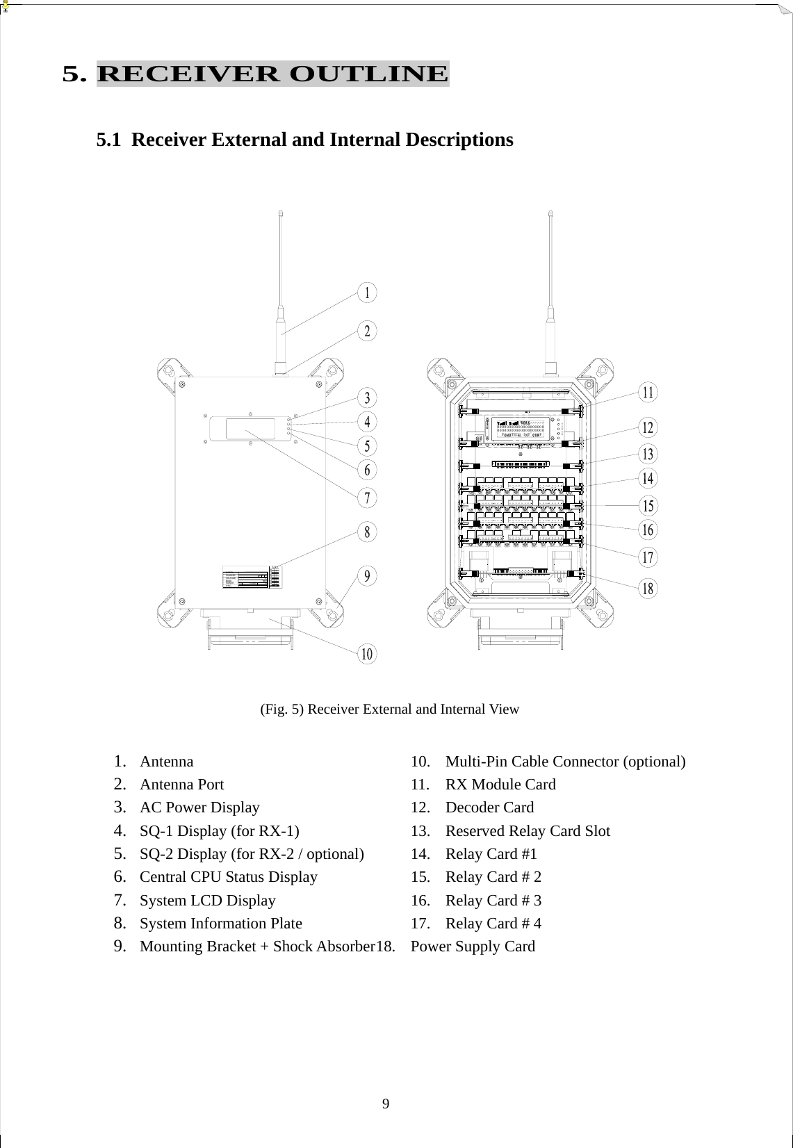
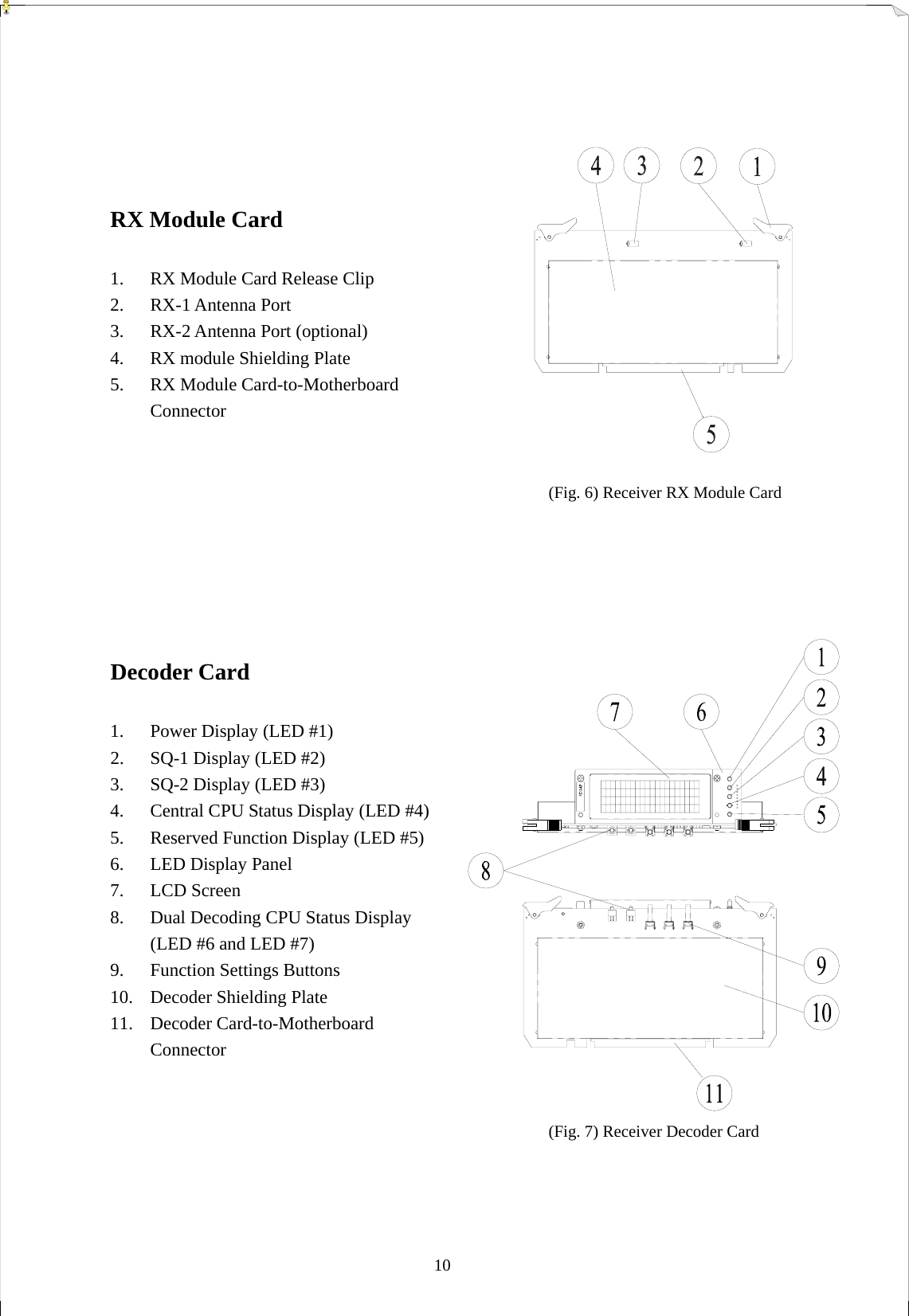
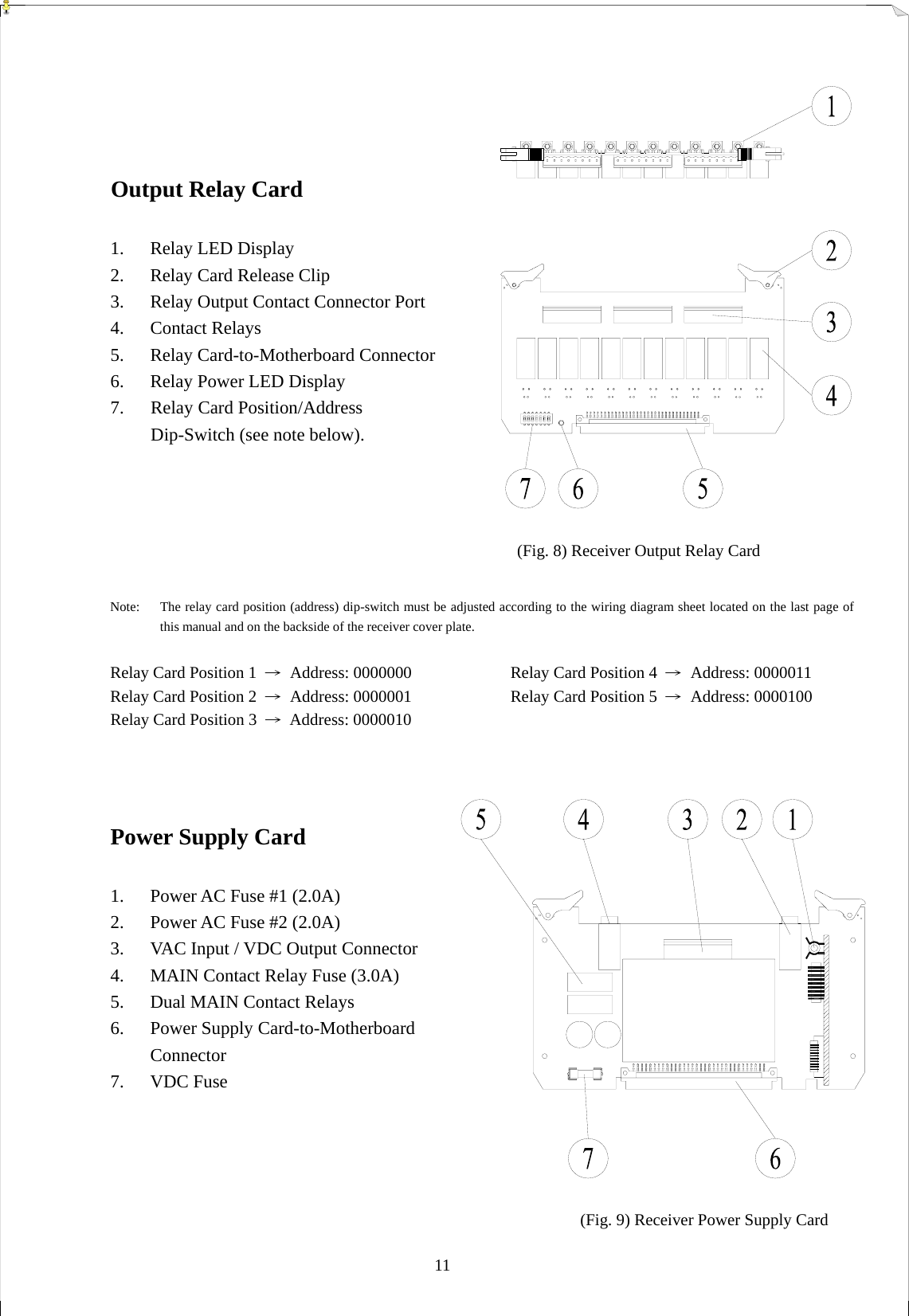
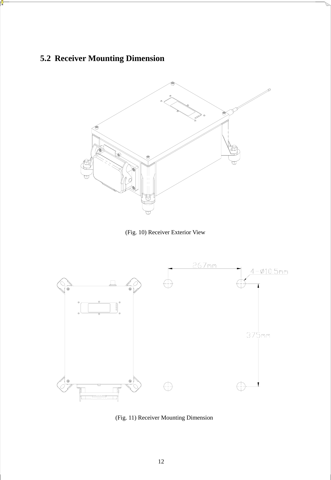
Fomotech TWISTER2X Industrial Remote Control User Manual Twister2X 99 910MHZ channels

Fomotech International Corp. Industrial Remote Control Twister2X 99 910MHZ channels

user manual

 1  TTAABBLLEE  OOFF  CCOONNTTEENNTTSS    Page   1.  INTRODUCTION  .................................................................................................   2 2.  SAFETY INSTRUCTIONS  ...................................................................................   3 3. SYSTEM FUNCTIONS   3.1 TRANSMITTER JOYSTICK DESCRIPTIONS ...........................................  4   3.2  TRANSMITTER PUSHBUTTON DESCRIPTIONS  ...................................    5   3.3  GENERAL FUNCTION DESCRIPTIONS  ...................................................   6 4. TRANSMITTER OUTLINE     4.1  TRANSMITTER EXTERNAL DESCRIPTIONS  .........................................    7 4.2  TRANSMITTER EXTERNAL DESCRIPTIONS  .........................................    8 5. RECEIVER OUTLINE 5.1  RECEIVER EXTERNAL & INTERNAL DESCRIPTIONS  .........................  9~11   5.2  RECEIVER MOUNTING DIMENSION  .......................................................  12 6. SYSTEM SETTINGS 6.1  TRANSMIITTER ID CODE SETTINGS  .....................................................  13 6.2  TRANSMITTER FREQUENCY CHANNEL SETTINGS  ...........................  13 6.3  RECEIVER LCD STATUS DISPLAYS  .........................................................  14 6.4  RECEIVER ID CODE & FREQUENCY CHANNEL SETTINGS  ...............  15 6.5 FREQUENCY CHANNEL TABLE  ...............................................................  16 7.  RECEIVER SYSTEM STATUS DISPLAYS  .........................................................  17~18 8. RECEIVER INSTALLATION   8.1 PREPARATION .............................................................................................  19 8.2 STEP-BY-STEP INSTALLATION .................................................................  19 8.3 SYSTEM TESTING .......................................................................................  20 9. OPERATING INSTRUCTION 9.1  POWER “ON” THE SYSTEM  .......................................................................  21 9.2  DUAL HOIST/TROLLEY OPERATION  .....................................................  22 9.3  TRANSMITTER SYSTEM STATUS DISPLAYS ...........................................  23 10. BATTERY CHARGING  .......................................................................................  24 11. SYSTEM SPECIFICATIONS  ...............................................................................   25~26 12. PARTS LIST  ...........................................................................................................  27
 2 1. INTRODUCTION  The Twister 2X is a highly sophisticated industrial radio remote control system.  The versatile features of Twister 2X permit its usage in a wide range of industrial applications.    The system can be used to control all types of industrial cranes, tower cranes, building construction equipment, automatic control systems, mining equipment, and many others.  The Twister 2X incorporates numerous advanced safety features and software programming that will ensure maximum security and safety in the workplace.    The major features of Twister 2X industrial radio remote control system are as follow:  *  The system is equipped with highly evolved software that has redundant error checking and correcting capabilities to ensure 100% error-free transmission, decoding, and control of all output relays.    This highly evolved software includes CRC (Cyclical Redundancy Check) and Hamming Codes (Error Recovery) programming.  *  The encoding system utilizes advanced microprocessor control for 100% error-free data transmission.  The availability of 65,536 sets of unique security ID codes + 20 distinct RF channels will ensure that only commands from a matching control transmitter can be carried out without any interference from other radio systems.        *  The decoding system utilizes dual-microprocessor control, which will ensure 100% error-free calculating, bit checking and correcting of all incoming data.                 *  The system also utilizes an additional central microprocessor for data comparison and crosschecking between the two decoding microprocessors.   When faults are detected via this central microprocessor, for maximum safety, the entire system will be shutdown immediately to avoid possibility of any accidents occurring.  *  The system utilizes PLL synthesized RF transmission.    It allows the user to select from 20 sets of frequency channels best suited for the environment.    The frequency channel is selected via simple dip-switch settings inside the transmitter unit.    The frequency channel for the receiver is selected via simple button setting on the receiver LCD control panel.    The receiver also has the ability to auto-scan from these 20 sets of frequency channels.    The receiver will search and locked on to the intended matching control transmitter.  *  For added safety the receiver also utilizes dual Safety Relay for the receiver MAIN relay circuit. If the receiver MAIN relay is defective (example: fails to open or close during operation or not responding to a “Stop” command) a fault will be detected and the system will be shut down immediately to avoid possibility of any accidents occurring.                *  The Twister 2X is equipped with numerous self-diagnosing functions, which include transmitter low-voltage detection/warning, faulty pushbutton/joystick detection, faulty safety MAIN relays detection, faulty relay boards detection, faulty EEPROM detection, faulty RX module detection, incorrect ID code detection, and receiver MAIN auto-deactivation when transmitter low-voltage is detected, when encountering strong radio interference, and when the transmitter/operator is out of receiving range.
 3 2. SAFETY INSTRUCTIONS  The Twister 2X system is relatively simple to use.  However, it is very important to observe the proper safety procedures before, during, and after operation.  When use properly the Twister 2X systems will enhance productivity and efficiency in the workplace.  The following instructions should be strictly followed:  1.  Make a daily check of the transmitter casing, joysticks and pushbuttons.    Should it appear that anything could inhibit the proper operation of the transmitter unit, it should be immediately removed from service.  2.  The transmitter voltage should be checked on a daily basis.    If the voltage is low, the battery pack should be recharged or replaced (refer to page 23 for battery power status LED display).      3.  The emergency stop button (EMS) should be checked at the beginning of each shift to ensure they are in the proper working order.        4.  In the event of an emergency, activate the emergency stop button immediately by pressing the red EMS button down.  This will immediately disconnect the transmitter power and receiver MAIN relays.    Then turned the power “off” from the main power source of the equipment.      5.  The transmitter power key, which is located on the right side of the transmitter box, should be turned “off” after each use and should never left the power key in “on” position when the unit is unattended.   6.  Do not use the same frequency channel and ID code as any other unit in use at the same facility or within distance of 300 meters.  7.  Ensure the waist belt and the shoulder strap is worn at all time during operation to avoid accidental damages to the transmitter box.  8.  Never operate a crane or equipment with two (2) transmitter units at the same time with same frequency channel and ID code.
 4 3. SYSTEM FUNCTIONS  3.1  Transmitter Joystick Descriptions  All transmitter units are equipped with two joysticks, in single or double axis configurations.    The table below illustrates the number of steps or speeds available for the Twister 2X in relation to each speed’s output contact relay configuration:  TYPE FUNCTION 1-Speed  1 speed output contact relay for both forward and reverse motion (total of 2 output relays per axis or motion) 2-Speed   Shared 2nd speed output contact relay for each forward and   reverse motion (total of 3 output relays per axis or motion)  2-Speed*  Separate 2nd speed output contact relay for each forward and   reverse motion (total of 4 output relays per axis or motion)     3-Speed  Shared 2nd and 3rd speed output contact relays for each forward   and reverse motion (total of 4 output relays per axis or motion) 4-Speed  Shared 2nd, 3rd and 4th speed output contact relays for each forward and reverse motion (total of 5 output relays per axis or motion)   5-Speed  Shared 2nd, 3rd, 4th and 5th speed output contact relays for each forward and reverse motion (total of 6 output relays per axis or motion)     0-Speed**  Addition of 0-speed (neutral position) output contact relay for   connection to crane’s braking system        * Separate 2nd speed output contact relay - For travel motion that required individual output contact relay for the 2nd speed function (example: hoist motion with dual motors).    **  By adding a 0-speed output contact relay, when the joystick is at center or neutral position, this 0-speed relay will be energized.  This feature is best suited for cranes or equipment with special breaking system.
 5  3.2  Transmitter Pushbutton Descriptions  There are many different types of pushbuttons and switches available for the Twister 2X, please refer to the chart below.  TYPE FUNCTION 1-Step Pushbutton  Pushbutton with momentary output contact relay 1-Step Electronic Toggled Pushbutton Resets itself when the transmitter unit is turned   “off” or when EMS button is activated Mechanical Toggled Pushbutton  Maintained toggled even after transmitter unit is turned   “off” or when EMS button is activated   2-Stage Mechanical Rocker Switch  0-T (refer to note 1 & 2) 2-Stage Mechanical Rocker Switch  0-R (refer to note 1) 3-Stage Mechanical Rocker Switch  T-0-T (refer to note 1 & 2) 3-Stage Mechanical Rocker Switch  R-0-T (refer to note 1 & 2) 3-Stage Mechanical Rocker Switch  T-0-R (refer to note 1 & 2) 3-Stage Mechanical Rocker Switch  R-0-R (refer to note 1) 2-Stage Mechanical Selector Switch  0-T (refer to note 1 & 2) 2-Stage Mechanical Selector Switch  0-R (refer to note 1) 3-Stage Mechanical Selector Switch  T-0-T (refer to note 1 & 2) 3-Stage Mechanical Selector Switch  T-0-R (refer to note 1 & 2) 3-Stage Mechanical Selector Switch  R-0-T (refer to note 1 & 2) 3-Stage Mechanical Selector Switch  R-0-R (refer to note 1) “ON/OFF” 1-Step Pushbuttons  Will reset to “off” position when transmitter unit is   turned “off” or after EMS reset    Note 1:  0    →   Neutral position.  T  →  Maintained position (toggled contact).  R →  Retract back to 0-position (momentary contact).    Note 2:  1-step pushbuttons, 2 & 3 stage mechanical rocker and selector switches with maintained toggled function (T) will remained energized (or closed) even when the power of the transmitter is turned off or when EMS is activated (Receiver Hold function).
 6  3.3  General Function Descriptions  Emergency Stop Button (Standard Equipped)  In case of an emergency, press down the red emergency stop button (EMS) will immediately deactivates the transmitter power and the receiver safety MAIN contact relays (refer to section 4.1 on page 7).    Transmitter Power Key (Standard Equipped)  All transmitters are equipped with two detachable power keys (one for spare) for turning the transmitter power “on” and “off” (refer to section 4.1 on page 7).  START button (Standard Equipped)  All transmitters are equipped with a START button for purpose of activating the receiver MAIN contact relay after turning on the transmitter power.    After turning “on” the transmitter unit via the transmitter power key, press and hold the START button for up to a second will activate the receiver MAIN contact relay.      After resetting the EMS button, by twisting the button 1/4 turn clockwise, the operator must also press and hold the START button for up to a second to reenergize the receiver MAIN contact relay.      Also, when the system is left unattended for 5 minutes or longer (system will go into sleep mode), the operator must again press and hold the START button for up to a second to reenergize the receiver MAIN contact relay.     Removable Relay Cards (Standard Equipped)  Special designed relay cards provided easy service maintenance and as well as for simplifying the inventory of spare parts.      Auto-Scanning Receiver (Standard Equipped)  When transmitter’s frequency channel (from channel 01 ~ 20) is changed via simple dip-switch setting inside the transmitter belly box, the receiver will search and locked on to the intended matching transmitter.  Tandem Feature / Dual-Crane Operation Feature (optional)  This feature allows two operators controlling two crane systems independently or one operator controlling two crane systems simultaneously (Crane A, Crane B, Crane A+B).  “Pitch And Catch” Feature (optional)  This feature allows two operators controlling one crane system from opposite ends of a long or cross travel.  Random Access Feature (optional)    This feature allows for up to 8 operators randomly accessing up to 8 crane systems via a 16-position mechanical selector switch and operate pitch/catch function via START/PITCH button.                  Infrared Initial Startup Feature (optional)    The feature allows system activation under or in close proximity to the crane or receiver via infrared transmission.    After infrared initial system activation, the frequency transmission will take over.
 74. TRANSMITTER OUTLINE     4.1  Transmitter External Descriptions               (Fig. 1) Transmitter Top View            (Fig. 2) Transmitter Bottom View         1.  Battery Power LED Display           2.    Status LED Display 3.    Information Top Plate (engraved) 4.   Left Joystick 5.   Right Joystick 6.   START Pushbutton 7.    AUX/RES Pushbutton (side panel) 8.    AUX/RES Pushbutton (top panel) 9.   AUX/RES Pushbutton (top panel)    10.    Emergency Stop Button (EMS) 11.    Power Key (detachable)   12.    Battery Contact (gold-plated)   13.  System Information 14. Battery slot    (Fig. 3) Transmitter Exterior Views   MODELVOLTAGEBANDPOWERS/NO.0123456789ACHANNEL A B CBC::::::VmMHzRXWTXW
 8  4.2  Transmitter Internal Descriptions                                                    (Fig. 4) RF Module, Encoder Board and Power Switch Views     1.  Encoder Shielding Plate      9.  Power Key Switch Connector Port     2.  Ribbon Type Connector Port    10.  Power Fuse (0.5A) 3.  Power Input Connector Port    11.  Infrared Startup Interface Port 4.  Charger Connector Port      12.  Antenna Port 5.  TX Module Connector Port    13.  TX module Connector 6.  ID Code Dip-Switch        14.  Power Key Switch Connector   7.  Frequency Channel Dip-Switch    15.  Power Key Switch 8.  External Programming Port
 90000000000000000000000000000000000000000FTEC I T 'P>>>>>>MODELVOLTAGEBANDPOWERS/NO.0123456789ACHANNEL A B CBC::::::VmMHzRXWTXW 5. RECEIVER OUTLINE  5.1  Receiver External and Internal Descriptions                                                            (Fig. 5) Receiver External and Internal View  1.  Antenna       10. Multi-Pin Cable Connector (optional) 2.  Antenna Port      11. RX Module Card 3.  AC Power Display          12.  Decoder Card 4.  SQ-1 Display (for RX-1)        13.  Reserved Relay Card Slot 5.  SQ-2 Display (for RX-2 / optional)    14.  Relay Card #1 6.  Central CPU Status Display      15.  Relay Card # 2 7.  System LCD Display        16.  Relay Card # 3 8.  System Information Plate       17.  Relay Card # 4 9.  Mounting Bracket + Shock Absorber 18.  Power Supply Card
 10     RX Module Card  1.  RX Module Card Release Clip 2. RX-1 Antenna Port 3.  RX-2 Antenna Port (optional) 4.  RX module Shielding Plate 5.  RX Module Card-to-Motherboard Connector    (Fig. 6) Receiver RX Module Card      Decoder Card  1.  Power Display (LED #1) 2.  SQ-1 Display (LED #2) 3.  SQ-2 Display (LED #3)     4.  Central CPU Status Display (LED #4) 5.  Reserved Function Display (LED #5) 6.  LED Display Panel 7. LCD Screen 8.  Dual Decoding CPU Status Display (LED #6 and LED #7) 9.  Function Settings Buttons 10.  Decoder Shielding Plate 11. Decoder Card-to-Motherboard Connector    (Fig. 7) Receiver Decoder Card
 11     Output Relay Card   1.  Relay LED Display     2.  Relay Card Release Clip 3.  Relay Output Contact Connector Port 4. Contact Relays 5.  Relay Card-to-Motherboard Connector 6.  Relay Power LED Display 7.  Relay Card Position/Address    Dip-Switch (see note below).                                  (Fig. 8) Receiver Output Relay Card    Note:  The relay card position (address) dip-switch must be adjusted according to the wiring diagram sheet located on the last page of this manual and on the backside of the receiver cover plate.      Relay Card Position 1  →  Address: 0000000      Relay Card Position 4  → Address: 0000011 Relay Card Position 2  →  Address: 0000001    Relay Card Position 5  → Address: 0000100  Relay Card Position 3  → Address: 0000010         Power Supply Card  1.  Power AC Fuse #1 (2.0A)   2.  Power AC Fuse #2 (2.0A) 3.  VAC Input / VDC Output Connector 4.  MAIN Contact Relay Fuse (3.0A) 5.  Dual MAIN Contact Relays 6.  Power Supply Card-to-Motherboard   Connector 7. VDC Fuse                                               (Fig. 9) Receiver Power Supply Card
 12  5.2  Receiver Mounting Dimension                                     (Fig. 10) Receiver Exterior View                              (Fig. 11) Receiver Mounting Dimension
 136. SYSTEM SETTINGS        6.1  Transmitter ID Code Settings     Transmitter ID code are set via an 8-position dip-switch located on the encoder board (refer to fig. 4 on page 8).    For receiver ID code settings please refer to section 6.3 & 6.4.                  Example: ID code  → 10010110               Top location : “1”       Bottom location : “0”          Note:    When transmitter ID code is altered please also make sure to readjust the receiver ID code accordingly.    System will not operate if the ID code on both the transmitter and receiver are different.       6.2  Transmitter Frequency Channel Settings    The transmitter frequency channel is also set via an 8-position dip-switch located on the encoder board (refer to fig. 4 on page 8).    For receiver frequency channel settings please refer to section 6.3 & 6.4.      For the below dip-switch with 00000001 setting, the RF channel is “01”, which also represents frequency “910.500MHz” (refer to frequency channel table on page 16).             Top location : “1”    Bottom location : “0”   Note:    When the frequency channel of the transmitter is altered please also make sure to readjust the receiver frequency channel accordingly.    System will not operate if the frequency channel on both the transmitter and receiver are different.
 14F I '00000000 0000 0000 0000 0000 0000 000000000000YS S1:F5I2:5P:1I:77-1111I  6.3  Receiver LCD Status Displays         (Screen “1”)        (Screen “2”)                   (Fig. 12) Receiver LCD Screen       1.  RX-1 Signal Strength         9.  ID Code-1 (regional code)     2.  RX-2 Signal Strength   (optional)    10.  ID Code-2 (system ID code) 3. System at Work      11. Decoder System-1  4.  Contact Relay Activation Display    12.  Decoder System-2     “0”→  relay OFF; “1”→  relay ON    13.  RX–1 Signal Strength 5.  EXIT/DOWN (-) Button (PS1)      14.  RX–2 Signal Strength (optional) 6.  EDIT/UP (+) Button (PS2)       15.  RX–1 Frequency Channel 7.  MODE/ENTER Button (PS3)      16.  RX–2 Frequency Channel (optional) 8. System Type
 151:2:P:1I:77-1111____ ______  6.4  Receiver ID Code & Frequency Channel Settings  Unlike the dip-switch setting on the transmitter, the receiver ID code and frequency channel can be easily adjusted via the LCD control panel on the receiver unit.  Please follow the step-by-step instructions illustrated below on how to change receiver ID code and frequency channel.                       (Screen “3”)       1)  To enter into screen “2”, press MODE/ENTER button one time. 2)  To enter into Screen “3”, press EDIT/UP (+) button for up to 5 seconds. 3)  TP (System type) and Country code cannot be changed (manufacture preset). 4)  Press EXIT/DOWN (-) button and EDIT/UP (+) buttons to change the ID code. 5)  Press MODE/ENTER button to proceed to the RX-1 setting column. 6)  Press EXIT/DOWN (-) button and EDIT/UP (+) button to change frequency channel of RX-1. 7)  Press MODE/ENTER button to proceed to RX-2 setting column. 8)  Press EXIT/DOWN (-) button and EDIT/UP (+) button to change frequency channel of RX-2. 9)  Press MODE/ENTER button to proceed to the UPDATE setting column. 10)  Press EDIT/UP (+) button to input “YES” as to save changes. 11)  Press EXIT/DOWN (-) button to input “NO” as to cancel changes. 12)  Press MODE/ENTER button to exit screen “3”.    Note A:  If new values are not inputted within 25 seconds, the system will exit the setup screen (screen “3”) and returned to screen “1”.    Note B:  If your system is not equipped with dual RX module, please skip step 7 through 8 described above.
 16 6.5 Frequency Channel Table    FREQUENCY   DIP-SWITCH SETTING  CHANNEL 910.500 MHz  00000001  01 910.550 MHz  00000010  02 910.600 MHz  00000011  03 910.650 MHz  00000100  04 910.700 MHz  00000101  05 910.750 MHz  00000110  06 910.800 MHz  00000111  07 910.850 MHz  00001000  08 910.900 MHz  00001001  09 910.950 MHz  00001010  10 911.000 MHz  00001011  11 911.050 MHz  00001100  12 911.100 MHz  00001101  13 911.150 MHz  00001110  14 911.200 MHz  00001111 15 911.250 MHz  00010000  16 911.300 MHz  00010001  17 911.350 MHz  00010010  18 911.400 MHz  00010011  19 911.450 MHz  00010100  20 911.500 MHz  00010101  21 911.550 MHz  00010110  22 911.600 MHz  00010111  23 911.650 MHz  00011000  24 911.700 MHz  00011001  25 911.750 MHz  00011010  26 911.800 MHz  00011011  27 911.850 MHz  00011100  28 911.900 MHz  00011101  29 911.950 MHz  00011110 30 912.000 MHz  00011111 31 912.050 MHz  00100000  32 912.100 MHz  00100001  33
 17FREQUENCY   DIP-SWITCH SETTING  CHANNEL 912.150 MHz  00100010  34 912.200 MHz  00100011  35 912.250 MHz  00100100  36 912.300 MHz  00100101  37 912.350 MHz  00100110  38 912.400 MHz  00100111  39 912.450 MHz  00101000  40 912.500 MHz  00101001  41 912.550 MHz  00101010  42 912.600 MHz  00101011  43 912.650 MHz  00101100  44 912.700 MHz  00101101  45 912.750 MHz  00101110  46 912.800 MHz  00101111 47 912.850 MHz  00110000  48 912.900 MHz  00110001  49 912.950 MHz  00110010  50 913.000 MHz  00110011  51 913.050 MHz  00110100  52 913.100 MHz  00110101  53 913.150 MHz  00110110  54 913.200 MHz  00110111  55 913.250 MHz  00111000  56 913.300 MHz  00111001  57 913.350 MHz  00111010  58 913.400 MHz  00111011  59 913.450 MHz  00111100 60 913.500 MHz  00111101 61 913.550 MHz  00111110 62 913.600 MHz  00111111 63 913.650 MHz  01000000  64 913.700 MHz  01000001  65 913.750 MHz  01000010  66 913.800 MHz  01000011  67 913.850 MHz  01000100  68 913.900 MHz  01000101  69 913.950 MHz  01000110  70
 18FREQUENCY   DIP-SWITCH SETTING  CHANNEL 914.000 MHz  01000111  71 914.050 MHz  01001000  72 914.100 MHz  01001001  73 914.150 MHz  01001010  74 914.200 MHz  01001011  75 914.250 MHz  01001100  76 914.300 MHz  01001101  77 914.350 MHz  01001110  78 914.400 MHz  01001111 79 914.450 MHz  01010000  80 914.500 MHz  01010001  81 914.550 MHz  01010010  82 914.600 MHz  01010011  83 914.650 MHz  01010100  84 914.700 MHz  01010101  85 914.750 MHz  01010110  86 914.800 MHz  01010111  87 914.850 MHz  01011000  88 914.900 MHz  01011001  89 914.950 MHz  01011010  90 915.000 MHz  01011011  91 915.050 MHz  01011100  92 915.100 MHz  01011101  93 915.150 MHz  01011110 94 915.200 MHz  01011111 95 915.250 MHz  01100000  96 915.300 MHz  01100001  97 915.350 MHz  01100010  98 915.400 MHz  01100011  99
 197. RECEIVER STATUS LED DISPLAYS                   (Fig 13) Receiver Status LED Display    1.  Receiver Power Display        4.  Central CPU Status Display 2.  SQ-1 (RX-1) Status Display      5.  LCD System Information Display 3.  SQ-2 (RX-2) Status Display  Receiver Power Display Should be lighted at all time when the system is turned on, if not, please check the input power source.    SQ-1 and SQ-2 Status Displays  Lights “on” →  Transmitted signals detected and received.  Lights “off” →  No transmitted signals detected.     Blinking lights when transmitter is turned “off”  →  Other radio interference.    Dual Decoding CPU Status Display (refer to Fig. 7 on page 10)     Lights “on” 0.1 second and “off” 1.0 second  →  Decoders on Standby.   Lights “on” 0.1 second and “off” 0.1 second  →  Decoding in Process.     Receiver Central CPU Status LED Display  LED INDICATION  REASON Slow Blinks (Green)  Standby   Fast Blinks (Green)  Transmitted signals received Fast Blinks (Red)  MAIN contact relays jammed or defective 3 Fast Blinks (Red)  RX module defective 4 Fast Blinks (Red)    EEPROM error 5 Fast Blinks (Red)  Incorrect transmitted ID code   6 Fast Blinks (Red)  Incorrect system type
 20YS S1:F5I2:5P:1I:77-1111I    Receiver Central CPU Status LCD Display   Some of the system status indications described on page 17 are also displayed on the receiver LCD screen for easy readout (screen “2”).  1) ID_ER    →    Incorrect transmitted ID code 2) MAIN_ER  →    Defective MAIN contact relay or relays   3) PLL_ER   →    Defective RX module     4) WORK   →    Transmitted signals received and decoded 5) SEARCH   →    System on standby 6) SCAN    →    System scanning for new frequency channel
 218. RECEIVER INSTALLATION   8.1 Preparation       1.  Required  Tools: 1)  Flat Head Screwdriver (- ) 2)  Phillips Head Screwdriver (+) 3) Multi-Meters 4)  14 mm Wrench X 2 5)  Power Drill with 10.5 ~ 11mm Drill-Bit 6) Output Cables  2.  Ensure receiver is not set to the same frequency channel and ID code as any other units in     use at the same facility or within distance of 300 meters.   3.  Prior to installation, make sure that the crane system itself is working properly. 4.  Use the multi-meter to check the voltage source available and ensure receiver voltage     setting is correct for this voltage. 5.  Prior to installation, switch off the main power source to the equipment.   8.2 Steps-By-Steps Installation  1.  Select a suitable location to mount the receiver. 2.  As much as possible, the location selected should have the antenna visible from all areas   where the transmitter is to be used. 3.  The location selected should not be exposed to high levels of electrical noise. 4.  Ensure the selected location has adequate space to accommodate the receiver enclosure. 5.  The distance between the antenna and the control panel should be as far apart as possible. 6.  Drill four holes on the control panel (10.5mm).       7.  Tightened all screws provided. 8.  For system wiring, please refer to the wiring diagram located on the last page of this     manual and on the backside of the receiver cover plate. 9.  Ensure all wiring is correct and safely secured and all screws are fastened.
 22                            8.3 System Testing  1.  Connect the power source to the receiver and test the operation of each function to   ensure it operates in the same manner as the pendant controller. 2.  Ensure the MAIN contact relay can be properly controlled by the remote control. 3.  Ensure the limit switches on the crane that limit all travels are working properly. 4.  Ensure the pendant controller is located in a safe location where it would not interfere   with remote operation.
 239. OPERATING INSTRUCTION   9.1  Power “ON” the System    1.  Insert the transmitter power key into the key-switch slot located on the right side of the transmitter belly box.  2.  Push the transmitter power key inward and then rotate it clockwise to “1” position. “1”  → “ON”    “0”  → “OFF”  3.  Make sure both joysticks are in their neutral (0-speed) position when transmitter power is turned “on”.    If the transmitter is turned “on” with the joystick in a non-neutral position, the transmitter will be temporarily disabled to avoid any unexpected crane movement at system startup.    If this situation occurs, just turn the transmitter power key “off” and then back “on” again with joystick in neutral position.    4.  Make sure that the red emergency stop button (EMS) is elevated before the transmitter power is turned on.  5.  To activate the receiver MAIN relay, press and hold the “START” pushbutton for up to 1.0 second.    The START pushbutton is located on the right side of the belly box, above the transmitter power key switch.      6.  After receiver MAIN relay activation (relay closed), if the operator did not give any command by pressing any pushbuttons or moving the joysticks to a non-neutral position, after 5 minutes of inactivity, the transmitter unit will go into “sleep mode” with receiver MAIN relay temporarily deactivated (relay opened).  To resume operation after 5 minutes of inactivity, just press and hold the “START” pushbutton again to reactivate the system.      7.  After 1 hour of inactivity, the transmitter power will be temporarily deactivated to save power.    8.  If the frequency channel of the transmitter unit is altered via simple dip-switch setting inside the transmitter (refer to page 13), you must then also change the frequency RF channel in the receiver (refer to page 15~16).  Since the receiver is equipped with frequency channel auto-scanning feature, after changing the frequency channel in the transmitter, you must then press and hold the START pushbutton for up to 20 seconds after turning “on” the transmitter power in order for the auto-scanning receiver to identify the newly selected channel.
 24  9.2  Dual Hoist/Trolley Operation  For system with dual hoist/trolley operation, use the 3-stage mechanical selector switch located between the two joysticks (refer to diagram below) to select which hoist and/or trolley to operate.  At position “I”, the main hoist and/or trolley are activated.  At position “II”, the auxiliary hoist and/or trolley are activated.    At position “I+II”, both main and auxiliary hoists and/or trolleys are activated with simultaneous travel movement.                    During system wiring, make sure to connect the Select-I output to the main hoist and/or trolley and Select-II output to auxiliary hoist and/or trolley.   When the selector switch is at position “I”, Select-I contact relay will close.    At position “II”, Select-II contact relay will close.    At position “I+II”, both Select-I and Select-II contact relay will close.    For system wiring, please refer to the system wiring schematic located on the last page of this manual or on the inner side of the receiver cover.
 25  9.3  Transmitter System Status Displays                 1.  Battery Power LED Display     2.  Transmitter Status LED Display    Transmitter Battery Power LED Display   POWER DISPLAY  REASON Constant Green  Battery level normal Slow Blinking Red  Low battery power (1st warning) Fast Blinking Red  Low battery power (2nd warning) Transmitter unit will stop transmitting at anytime   Constant Red    Low battery power (3rd warning) Transmitter power and receiver MAIN relay deactivated   Transmitter Status LED Display STATUS DISPLAY  REASON No Light Displayed    Transmitter in sleep mode with receiver MAIN relay deactivatedSlow Blinks (Green)  Transmitter on standby   Fast Blinks (Green)  Transmitter active   Constant Red Light  Jammed or defective pushbutton, switch or joystick contacts Fast Blinks (Red)  The contact point currently in use is operative (refer to note A) 3 Fast Blinks (Red)  PLL TX module defective 4 Fast Blinks (Red)  EEPROM error   Note A:  When there is a defective or jammed pushbutton, switch or joystick contacts, the transmitter status LED will display a constant red light without flashes.  To find out which contact is defective or jammed, activate each pushbuttons, switches or joysticks a step at a time by holding at each position for up to 2 seconds.   If a flashing red light (blinks rapidly) is displayed at a specific position, it means that the contact point for that particular position is operative.    If the lights remained constantly red at a certain position, then it means that this position’s contact is either jammed or defective.  The main purpose of function is to let the user realize which contact on the transmitter is not working properly and required service immediately.
 26 10.BATTERY CHARGING   1.  Plug in the power cord and the power indicator will light up. 2.  When a battery pack is inserted, the green charging light will blink to indicate charging is taking place at the current moment. 3.  If discharging of battery pack is desired (strongly recommended for 600mA NiCd battery pack), press the “DISCHARGE” button.  At discharging mode, the green blinking light will now turned into a constant red light indicating that the battery pack is now being discharged.    If you want to cancel the discharge, just press “DISCHARGE” button again. 4.  When discharging is completed, the charger will automatically switch to the charging mode where the green blinking light will reappear again. 5.  The charging time for a 600mA NiCd battery pack is approximately 3 ~ 6 hours.   As for the 1450mA NiMH battery pack, the charging time is approximately 7 ~ 9 hours. 6.  When charging is completed, a constant green light will appear to indicate that the battery pack is fully charged. 7.  When the battery pack is at 90% charged state, trickle charging will take over to ensure the longevity of the battery pack and as well as to ensure the battery pack is 100% charged. 8.  When the battery pack’s temperature exceeds 50℃, the charger will go into protective mode and charging will be discontinued.     9.  To prolong the life of the battery pack (600mA NiCd battery pack), it is recommended that the battery pack be fully discharged prior to every re-charging.
 27 11.SYSTEM SPECIFICATION  Transmitter Unit  Frequency Range          :    PLL 910.500 ~915.400 MHz   Transmitting Range:       :    100 Meters      Continuous Operating Time    :    37.7+ Hours (1650mA)   Security ID Code        :    65,536 sets (16 + 1 bit)   Channel Spacing    :  50KHz Hamming Distance    :  ≧ 6 Frequency Control    :  Synthesizer (PLL) Frequency Drift        :    < 3ppm @ -25℃ ~ 75℃ Frequency Deviation      :    < 1ppm @ 25℃ Spurious Emission    :  > 60dBc Transmitting Power    :  0.043mW   Emission      :  F1D Antenna Impedance    :  50 ohms Enclosure Rating    :  IP-66 Source Voltage    :  7.2 V (1650mA) Current Drain     :  ~80mA Operating Temperature   :  -10℃ ~ 75℃ Dimension          :    247mm X 154mm X 182mm Weight            :    1,600g (with 1650mA battery pack)  Note:  Longer or shorter transmitting ranges are available upon request.
 28  Receiver Unit    Frequency Range        :    PLL910.500 ~915.400 MHz Channel Spacing    :  50KHz Hamming Distance    :  ≧  6 Frequency Control    :  Synthesizer (PLL) Frequency Drift        :    < 3ppm @ -10℃ ~ 75℃ Frequency Deviation      :    1ppm @ 25℃ Sensitivity     :  -115dBm Decoding Reference    :  FSK   Antenna Impedance    :  50 ohms Data Decoder Reference      :    Quartz Crystals Responding Time    :  100mS ~ 300mS Enclosure Rating    :  IP-66 Source Voltage    :  100 ~ 240VAC @ 50/60 Hz. (standard equipped)   Power Consumption    :  36VA Operating Temperature   :  -10℃ ~ 75℃ Output Contact Rating      :    250V @ 10A Dimension          :    417mm X 309mm X 167mm Weight            :    8,800g (without the output cable)  Note:  Other types of source voltages are available upon request.
 29 12.PARTS LIST  1.  TX module (please specify frequency band)            TX5000   2.  RX module card (please specify frequency band)           RX5000 3. Encoder board            EN5000 4. Decoder card            DE5000 5. Relay card             RY5000 6.  Power supply card (100 ~ 240VAC)                PS5000   Power supply card (48VAC)         PS5001   Power supply card (24VDC)         PS5002   Power supply card (380VAC)         PS5003     Power supply card (400 ~ 420VAC)                PS5004 7. Single axis joystick unit (complete)           2 speeds / steps            JOY-12 3 speeds / steps            JOY-13 4 speeds / steps            JOY-14 5 speeds / steps            JOY-15 8.  Double axis joystick unit (complete)             2 speeds / steps            JOY-22 3 speeds / steps            JOY-23   4 speeds / steps            JOY-24   5 speeds / steps            JOY-25 9. 1-step pushbutton (side panel)         PB-1S 10. 1-step pushbutton (top panel)         PB-1T 11. 2-stage selector switch            SW-2T  12. 3-stage selector switch          SW-3T 13. 2-stage toggle switch           TW-2T 14. 3-stage toggle switch           TW-3T 15. Emergency stop button          EM5000 16. Transmitter casing (complete)         TC5000   18. Transmitter protective guardrail         PG5000 19. Transmitter power key          PW5000 20. 1650mA NiMH battery pack         BAT1650 21. Receiver antenna (433 MHz ~ 434 MHz)              ANT433 22. Receiver antenna (910.500 ~915.400 MHz)             ANT910 23. Receiver enclosure (complete)         RC5000 24. Intelligent charger (please specify voltage)              CH5000 25. Waist Belt             WB5000 26. Shoulder Strap            SS5000

Navigation menu