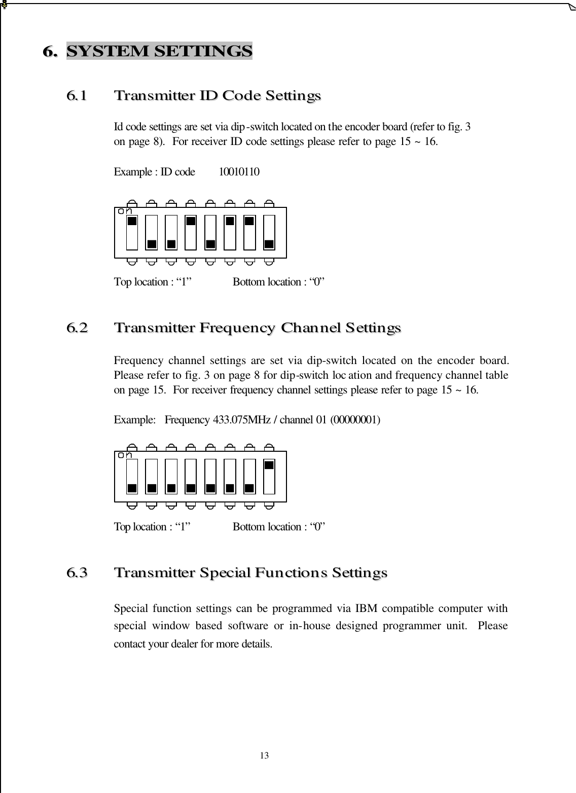
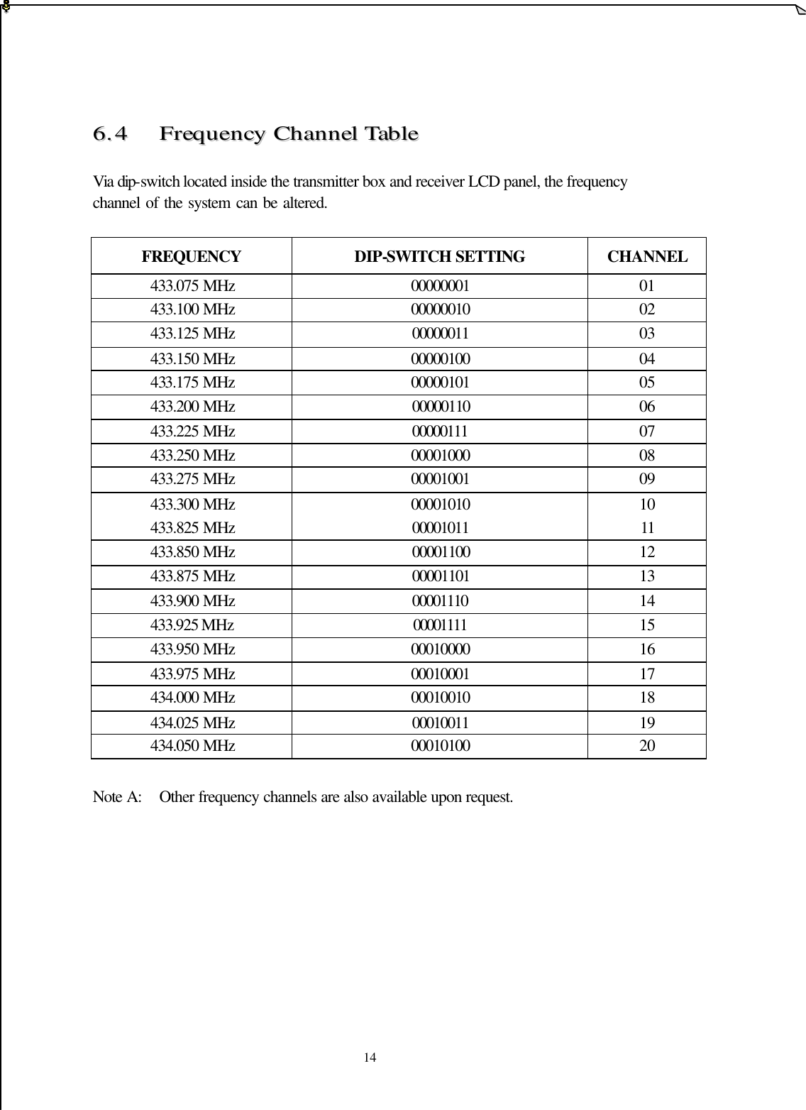
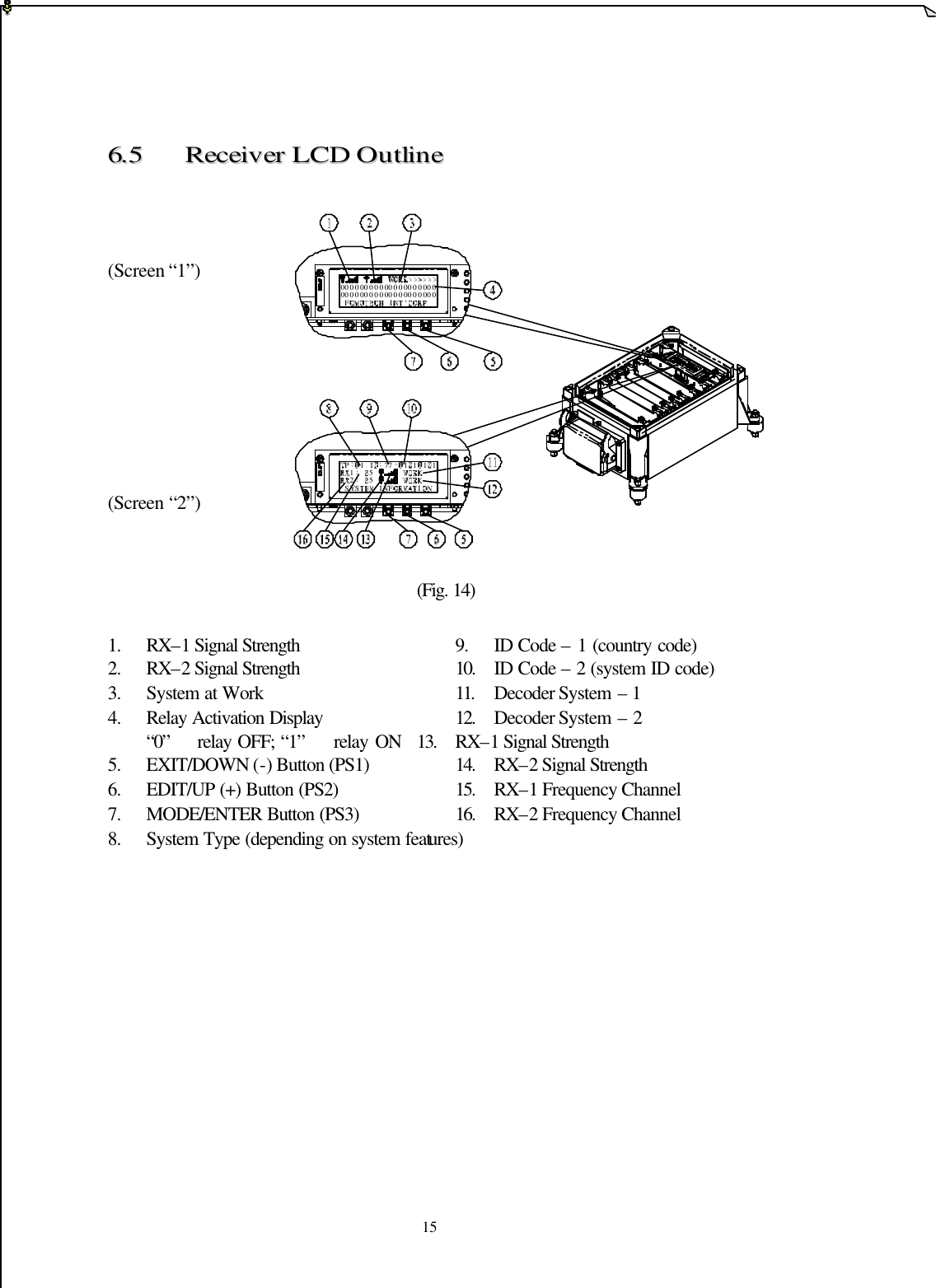
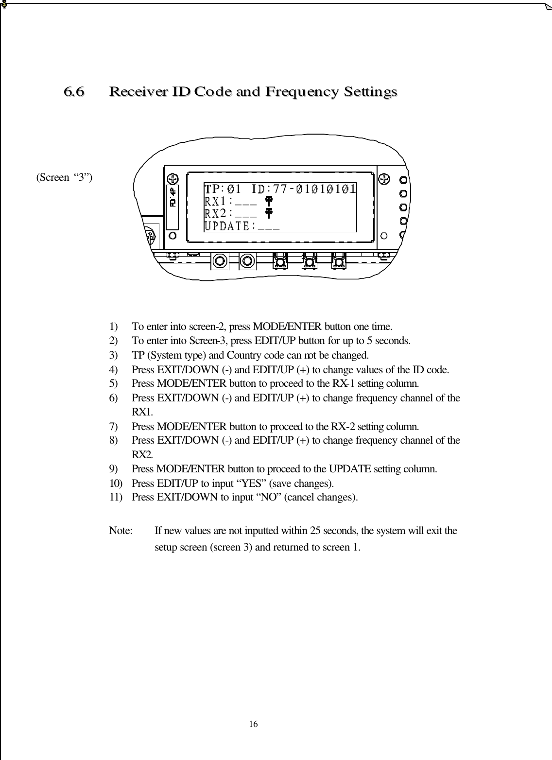
Fomotech TWISTER2XA5000 Industrial Radio Control System User Manual manual
Fomotech International Corp. Industrial Radio Control System manual
UserManual.wiki
>
Fomotech
>
TWISTER2XA5000 User Manual
>
manual
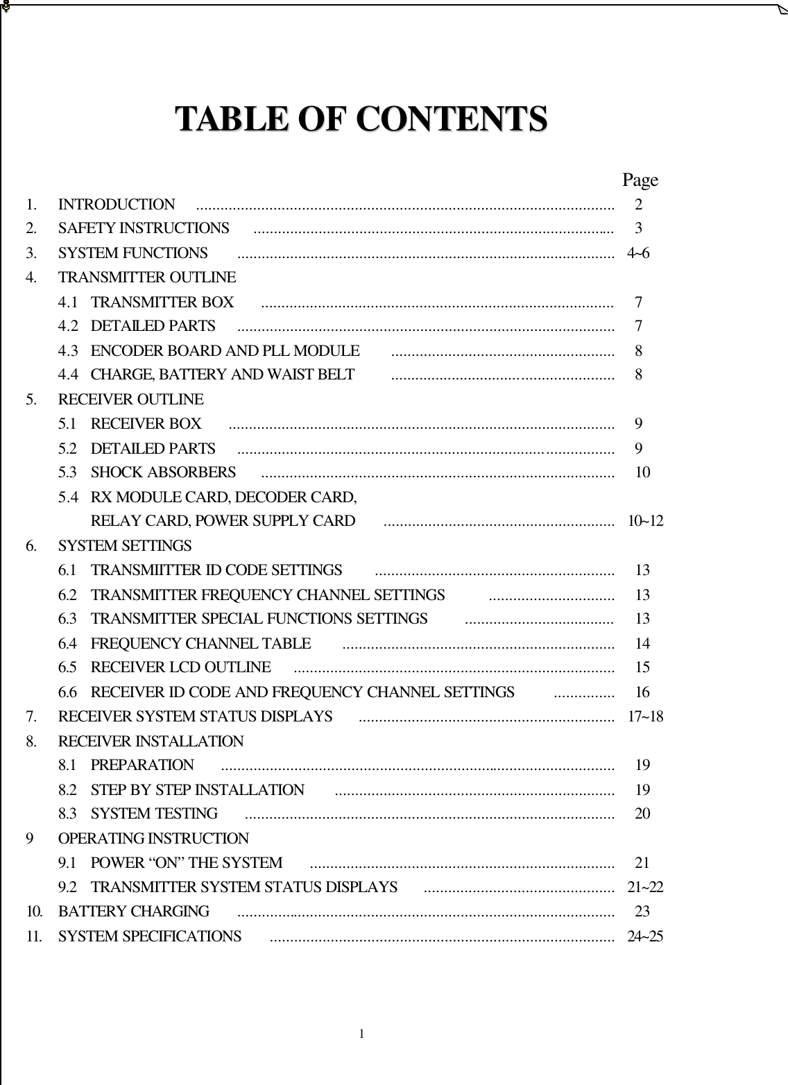
Contents
1.
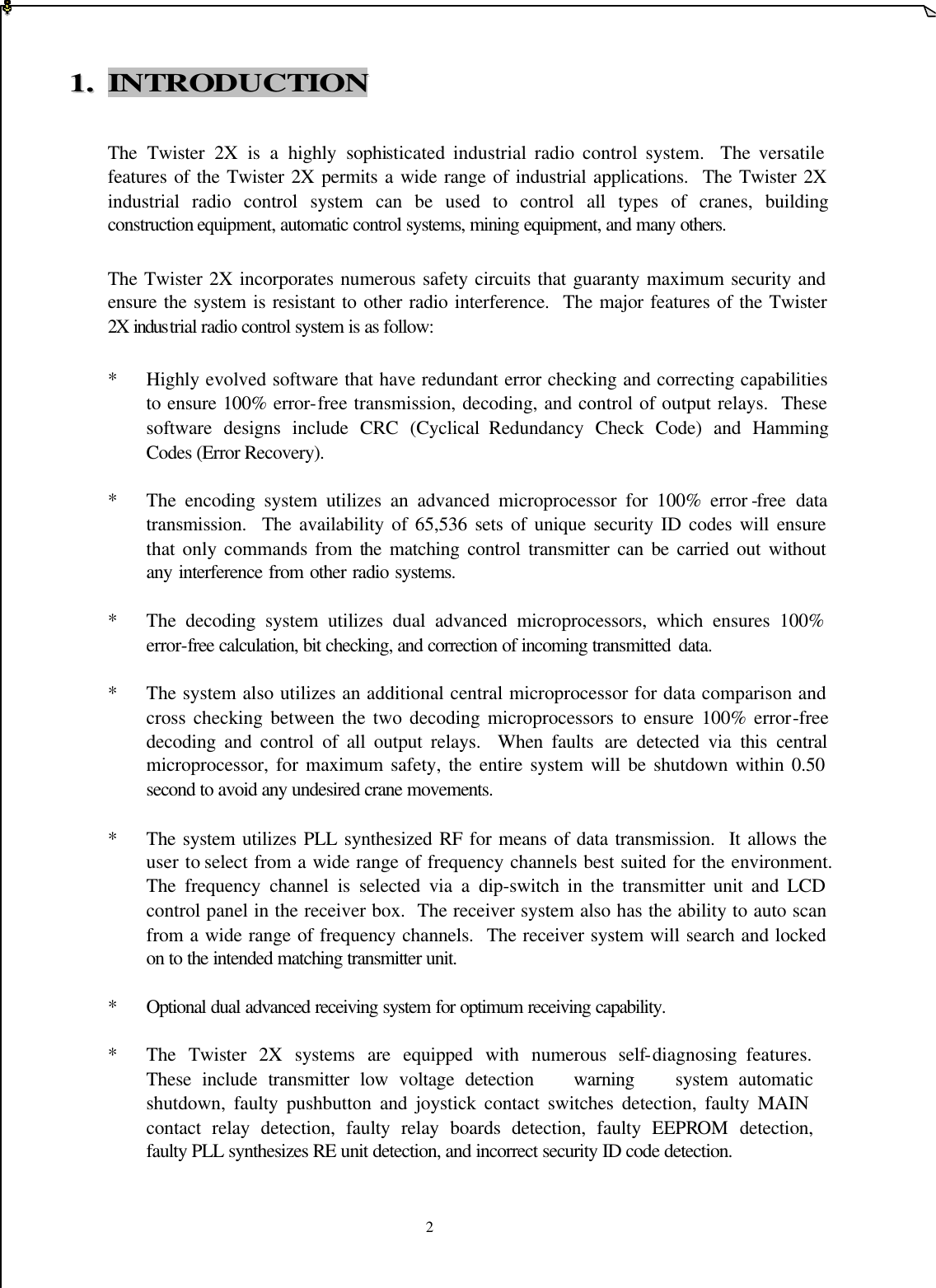
manual cover page
2.
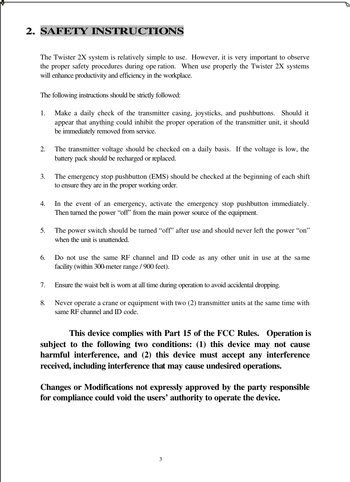
manual
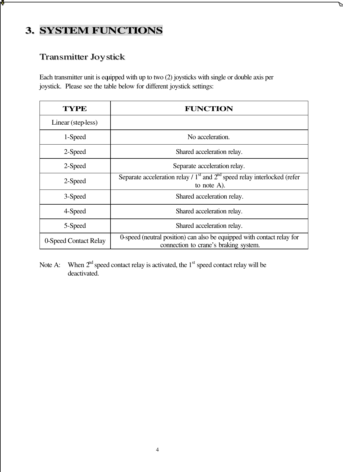
manual
Navigation menu
Upload a User Manual
Namespaces
Wiki Guide
HTML
PDF
Info
Views
User Manual
Discussion / Help
Navigation