Fomotech TWISTER2XA5000 Industrial Radio Control System User Manual manual
Fomotech International Corp. Industrial Radio Control System manual
Fomotech >
Contents
- 1. manual cover page
- 2. manual
manual

1
T
TA
AB
BL
LE
E
O
OF
F
C
CO
ON
NT
TE
EN
NT
TS
S
Page
1. INTRODUCTION ....................................................................................................... 2
2. SAFETY INSTRUCTIONS ......................................................................................... 3
3. SYSTEM FUNCTIONS ............................................................................................. 4~6
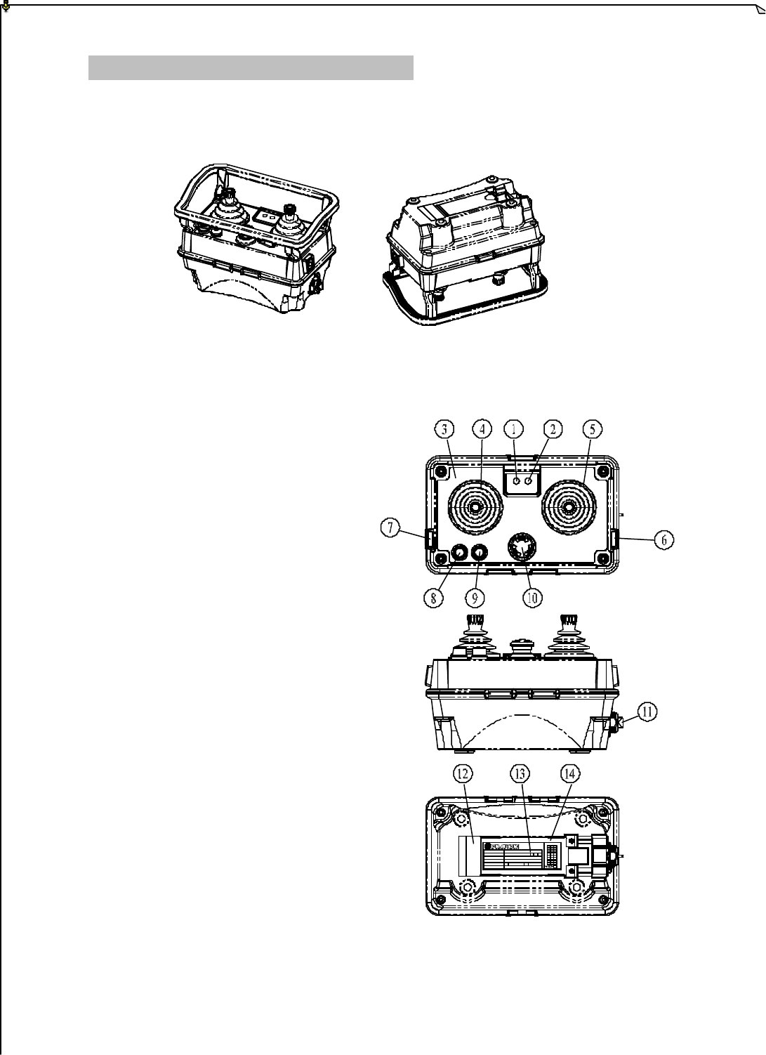
4. TRANSMITTER OUTLINE
4.1 TRANSMITTER BOX ....................................................................................... 7
4.2 DETAILED PARTS ............................................................................................. 7
4.3 ENCODER BOARD AND PLL MODULE ....................................................... 8
4.4 CHARGE, BATTERY AND WAIST BELT ....................................................... 8
5. RECEIVER OUTLINE
5.1 RECEIVER BOX ............................................................................................... 9
5.2 DETAILED PARTS ............................................................................................. 9
5.3 SHOCK ABSORBERS ....................................................................................... 10
5.4 RX MODULE CARD, DECODER CARD,
RELAY CARD, POWER SUPPLY CARD ......................................................... 10~12
6. SYSTEM SETTINGS
6.1 TRANSMIITTER ID CODE SETTINGS ........................................................... 13
6.2 TRANSMITTER FREQUENCY CHANNEL SETTINGS ............................... 13
6.3 TRANSMITTER SPECIAL FUNCTIONS SETTINGS ..................................... 13
6.4 FREQUENCY CHANNEL TABLE ................................................................... 14
6.5 RECEIVER LCD OUTLINE ............................................................................... 15
6.6 RECEIVER ID CODE AND FREQUENCY CHANNEL SETTINGS ............... 16
7. RECEIVER SYSTEM STATUS DISPLAYS ............................................................... 17~18
8. RECEIVER INSTALLATION
8.1 PREPARATION ................................................................................................. 19
8.2 STEP BY STEP INSTALLATION ..................................................................... 19
8.3 SYSTEM TESTING ........................................................................................... 20
9 OPERATING INSTRUCTION
9.1 POWER “ON” THE SYSTEM ........................................................................... 21
9.2 TRANSMITTER SYSTEM STATUS DISPLAYS ............................................... 21~22
10. BATTERY CHARGING ............................................................................................. 23
11. SYSTEM SPECIFICATIONS ..................................................................................... 24~25

2
1
1.
.
I
IN
NT
TR
RO
OD
DU
UC
CT
TI
IO
ON
N
The Twister 2X is a highly sophisticated industrial radio control system. The versatile
features of the Twister 2X permits a wide range of industrial applications. The Twister 2X
industrial radio control system can be used to control all types of cranes, building
construction equipment, automatic control systems, mining equipment, and many others.
The Twister 2X incorporates numerous safety circuits that guaranty maximum security and
ensure the system is resistant to other radio interference. The major features of the Twister
2X industrial radio control system is as follow:
* Highly evolved software that have redundant error checking and correcting capabilities
to ensure 100% error-free transmission, decoding, and control of output relays. These
software designs include CRC (Cyclical Redundancy Check Code) and Hamming
Codes (Error Recovery).
* The encoding system utilizes an advanced microprocessor for 100% error -free data
transmission. The availability of 65,536 sets of unique security ID codes will ensure
that only commands from the matching control transmitter can be carried out without
any interference from other radio systems.
* The decoding system utilizes dual advanced microprocessors, which ensures 100%
error-free calculation, bit checking, and correction of incoming transmitted data.
* The system also utilizes an additional central microprocessor for data comparison and
cross checking between the two decoding microprocessors to ensure 100% error-free
decoding and control of all output relays. When faults are detected via this central
microprocessor, for maximum safety, the entire system will be shutdown within 0.50
second to avoid any undesired crane movements.
* The system utilizes PLL synthesized RF for means of data transmission. It allows the
user to select from a wide range of frequency channels best suited for the environment.
The frequency channel is selected via a dip-switch in the transmitter unit and LCD
control panel in the receiver box. The receiver system also has the ability to auto scan
from a wide range of frequency channels. The receiver system will search and locked
on to the intended matching transmitter unit.
* Optional dual advanced receiving system for optimum receiving capability.
* The Twister 2X systems are equipped with numerous self-diagnosing features.
These include transmitter low voltage detection warning system automatic
shutdown, faulty pushbutton and joystick contact switches detection, faulty MAIN
contact relay detection, faulty relay boards detection, faulty EEPROM detection,
faulty PLL synthesizes RE unit detection, and incorrect security ID code detection.

3
2
2.
.
S
SA
AF
FE
ET
TY
Y
I
IN
NS
ST
TR
RU
UC
CT
TI
IO
ON
NS
S
The Twister 2X system is relatively simple to use. However, it is very important to observe
the proper safety procedures during ope ration. When use properly the Twister 2X systems
will enhance productivity and efficiency in the workplace.
The following instructions should be strictly followed:
1. Make a daily check of the transmitter casing, joysticks, and pushbuttons. Should it
appear that anything could inhibit the proper operation of the transmitter unit, it should
be immediately removed from service.
2. The transmitter voltage should be checked on a daily basis. If the voltage is low, the
battery pack should be recharged or replaced.
3. The emergency stop pushbutton (EMS) should be checked at the beginning of each shift
to ensure they are in the proper working order.
4. In the event of an emergency, activate the emergency stop pushbutton immediately.
Then turned the power “off” from the main power source of the equipment.
5. The power switch should be turned “off” after use and should never left the power “on”
when the unit is unattended.
6. Do not use the same RF channel and ID code as any other unit in use at the same
facility (within 300-meter range / 900 feet).
7. Ensure the waist belt is worn at all time during operation to avoid accidental dropping.
8. Never operate a crane or equipment with two (2) transmitter units at the same time with
same RF channel and ID code.
This device complies with Part 15 of the FCC Rules. Operation is
subject to the following two conditions: (1) this device may not cause
harmful interference, and (2) this device must accept any interference
received, including interference that may cause undesired operations.
Changes or Modifications not expressly approved by the party responsible
for compliance could void the users’ authority to operate the device.

4
3
3.
.
S
SY
YS
ST
TE
EM
M
F
FU
UN
NC
CT
TI
IO
ON
NS
S
T
Tr
ra
an
ns
sm
mi
it
tt
te
er
r
J
Jo
oy
ys
st
ti
ic
ck
k
Each transmitter unit is equipped with up to two (2) joysticks with single or double axis per
joystick. Please see the table below for different joystick settings:
TYPE FUNCTION
Linear (step-less)
1-Speed No acceleration.
2-Speed Shared acceleration relay.
2-Speed Separate acceleration relay.
2-Speed Separate acceleration relay / 1st and 2nd speed relay interlocked (refer
to note A).
3-Speed Shared acceleration relay.
4-Speed Shared acceleration relay.
5-Speed Shared acceleration relay.
0-Speed Contact Relay 0-speed (neutral position) can also be equipped with contact relay for
connection to crane’s braking system.
Note A: When 2nd speed contact relay is activated, the 1st speed contact relay will be
deactivated.

5
T
Tr
ra
an
ns
sm
mi
it
tt
te
er
r
P
Pu
us
sh
hb
bu
ut
tt
to
on
ns
s
There are many different types of pushbuttons and switches available for the Twister 2X; please
refer to the chart below.
TYPE FUNCTION
1-Step Pushbutton Standard non-toggled pushbutton
2-Step Pushbutton Standard non-toggled pushbutton
Mechanical Toggle Pushbutton Standard toggled pushbutton
Electronic Toggle Pushbutton Resets itself when the transmitter unit is turned “off”
Rocker Switch 0-T (refer to note 1 & 2)
Rocker Switch 0-R (refer to note 1)
Rocker Switch R-0 (refer to note 1)
Rocker Switch T-0-T (refer to note 1 & 2)
Rocker Switch R-0-T (refer to note 1 & 2)
Rocker Switch T-0-R (refer to note 1 & 2)
Rocker Switch R-0-R (refer to note 1)
Selector Switch 0-T (refer to note 1 & 2)
Selector Switch 0-R (refer to note 1)
Selector Switch T-0-T (refer to note 1 & 2)
Selector Switch T-0-R (refer to note 1 & 2)
Selector Switch R-0-T (refer to note 1 & 2)
Selector Switch R-0-R (refer to note 1)
ON / OFF Pushbuttons 2 pushbuttons per set / interlocked / will reset to “off”
position when transmitter unit is turned “off”
Note 1: 0 Original position.
T Maintain position (toggled).
R Retract to the 0-position (non-toggled).
Note 2: Pushbuttons, rocker switches, and selector switches with T (toggled) settings can
also have their contact relay in the receiver to stay activated even if the transmitter
unit is turned “off”.

6
E
Em
me
er
rg
ge
en
nc
cy
y
S
St
to
op
p
B
Bu
ut
tt
to
on
n
(
(E
EM
MS
S)
)
In case of an emergency, press the Emergency Stop Button will immediately deactivates the
transmitter unit and the receiver MAIN Contact Relay.
P
Po
ow
we
er
r
K
Ke
ey
y
S
Sw
wi
it
tc
ch
h
Key switch for activating the power of the transmitter unit (please refer to Fig. 2 on page 7).
S
St
ta
ar
rt
t
P
Pu
us
sh
hb
bu
ut
tt
to
on
n
After turning “on” the transmitter unit via power key switch, press the START pushbutton
will activate the receiver MAIN. After resetting the emergency stop button, pressing the
START pushbutton will also activate the receiver MAIN.
R
Re
em
mo
ov
va
ab
bl
le
e
R
Re
el
la
ay
y
C
Ca
ar
rd
ds
s
The special designed relay cards with main motherboard for future system expandability and
replacements.
A
Au
ut
to
o
S
Sc
ca
an
nn
ni
in
ng
g
R
Re
ec
ce
ei
iv
ve
er
r
When the transmitter unit’s frequency channel is changed, the receiver unit will search and
locked on to the intended matching transmitter unit.
O
Op
pt
ti
io
on
na
al
l
F
Fe
ea
at
tu
ur
re
es
s
1. Pitch and Catch Mode – This feature allows two operators controlling one crane system
from opposite ends of a long travel.
2. Tandem Mode – This feature allows two operators controlling two crane systems
independently or one operator controlling two crane systems simultaneously.
3. Random Access – This function allows for up to eight operators randomly accessing
eight crane systems via an eight-position selector switch.
7
4
4.
.
T
TR
RA
AN
NS
SM
MI
IT
TT
TE
ER
R
O
OU
UT
TL
LI
IN
NE
E
4
4.
.1
1
T
Tr
ra
an
ns
sm
mi
it
tt
te
er
r
B
Bo
ox
x
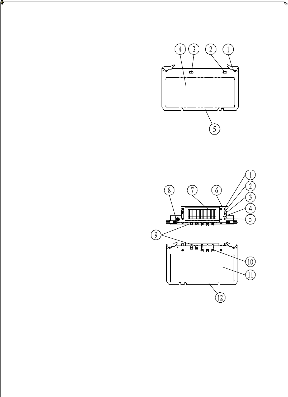
(Fig. 1)
4
4.
.2
2
D
De
et
ta
ai
il
le
ed
d
P
Pa
ar
rt
ts
s
1. Power Status LED Display
2. Signal Status LED Display
3. Information Plate (engraved)
4. Left Joystick Rubber Boot
5. Right Joystick Rubber Boot
6. START Pushbutton
7. AUX/RES Pushbutton
8. AUX/RES Pushbutton
9. AUX/RES Pushbutton
10. Emergency Stop Button (EMS)
11. Power Key Switch (removable)
12. Battery Contact
13. System Information
14. Battery slot
(Fig. 2)
MODEL
VOLTAGE
BAND
POWER
S/NO. 0
1
2
3
4
5
6
7
8
9A
CHANNEL A B C
BC
:
:
:
:
:
:
V
mMHz
RXWTXW
8
4
4.
.3
3
E
En
nc
co
od
de
er
r
B
Bo
oa
ar
rd
d
a
an
nd
d
P
PL
LL
L
M
Mo
od
du
ul
le
e
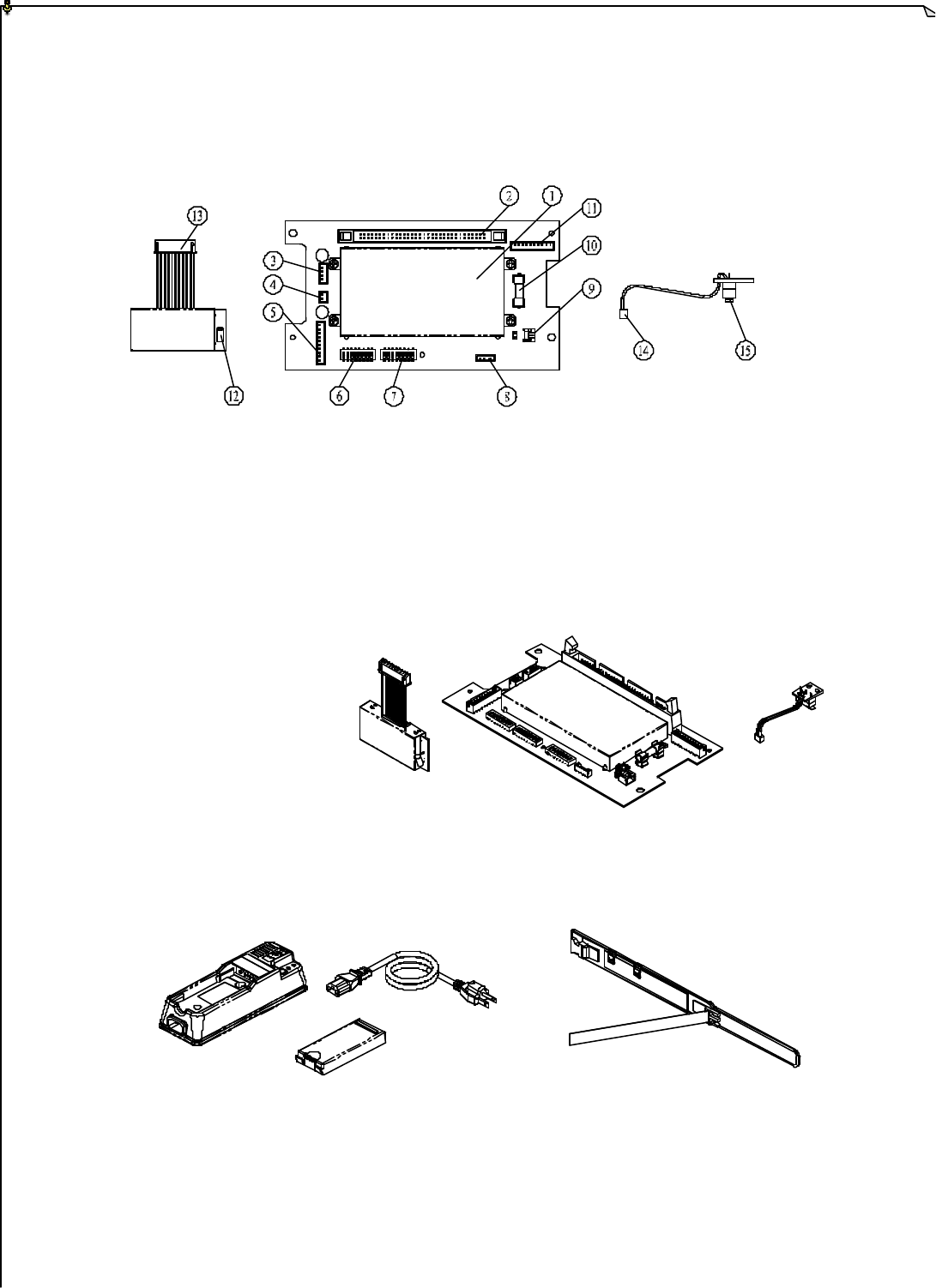
(Fig. 3)
1. Encoder Shield Plate 9. Power Key Switch Connector Port
2. Ribbon Type Connector Port 10. Power Fuse (0.25A)
3. Power Input Connector Port 11. Infrared Interface Port
4. Charger Connector Port 12. Antenna Port
5. TX Module Connector Port 13. TX module Connector
6. ID Code Dip-Switch 14. Power Key Switch Connector
7. Frequency Channel Dip-Switch 15. Power Key Switch
8. Programming Port
(Fig. 4)
4
4.
.4
4
I
In
nt
te
el
ll
li
ig
ge
en
nt
t
C
Ch
ha
ar
rg
ge
er
r,
,
6
60
00
0m
mA
A
B
Ba
at
tt
te
er
ry
y
P
Pa
ac
ck
k
x
x
2
2,
,
W
Wa
ai
is
st
t
B
Be
el
lt
t,
,
a
an
nd
d
S
Sh
ho
ou
ul
ld
de
er
r
S
St
tr
ra
ap
p
(Not Pictured)
(Fig. 5)
9
5
5.
.
R
RE
EC
CE
EI
IV
VE
ER
R
O
OU
UT
TL
LI
IN
NE
E
5
5.
.1
1
R
Re
ec
ce
ei
iv
ve
er
r
B
Bo
ox
x
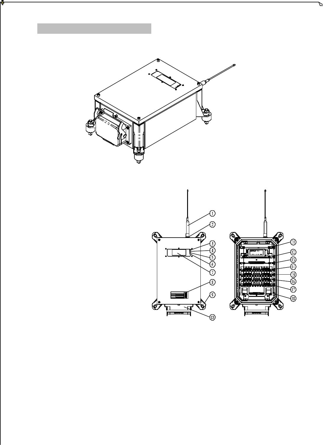
(Fig. 5)
(Fig. 6)
5
5.
.2
2
D
De
et
ta
ai
il
l
P
Pa
ar
rt
ts
s
1. Antenna
2. Antenna Port
3. Power Display
4. SQ-1 Display (RX-1)
5. SQ-2 Display (RX-2)
6. Central CPU Status Display
7. System LCD Display
8. System Information Plate
9. Shock Absorber Leg (Fig. 7)
10. Heavy Duty Cable Connector
11. RX Module Card 15. Relay Card – 2
12. Decoder Card 16. Relay Card – 3
13. Reserved Relay Card 17. Relay Card – 4
14. Relay Card – 1 18. Power Transformer Card
0
0 0
0
0
0
0
0
0
0
0
0
0
0
0
0
0
0
0
0
0
0
0
0
0
0
0
0
0
0
0
0
0
0
0
0
0
0
0
0
FT ECIT'P
> >> >> >
MODEL
VOLTAGE
BAND
POWER
S/NO. 0
1
2
3
4
5
6
7
8
9A
CHANNEL ABC
BC
:
:
:
:
:
:
V
mMHz
RXWTXW
10
5
5.
.3
3
S
Sh
ho
oc
ck
k
A
Ab
bs
so
or
rb
be
er
rs
s
(Fig. 8)
5
5.
.4
4
R
RX
X
M
Mo
od
du
ul
le
e
C
Ca
ar
rd
d
(
(1
1)
),
,
D
De
ec
co
od
de
er
r
C
Ca
ar
rd
d
(
(2
2)
),
,
R
Re
el
la
ay
y
C
Ca
ar
rd
d
(
(3
3)
),
,
P
Po
ow
we
er
r
S
Su
up
pp
pl
ly
y
C
Ca
ar
rd
d
(
(4
4)
)
(Fig. 9)
(1) (2) (3) (4)
11
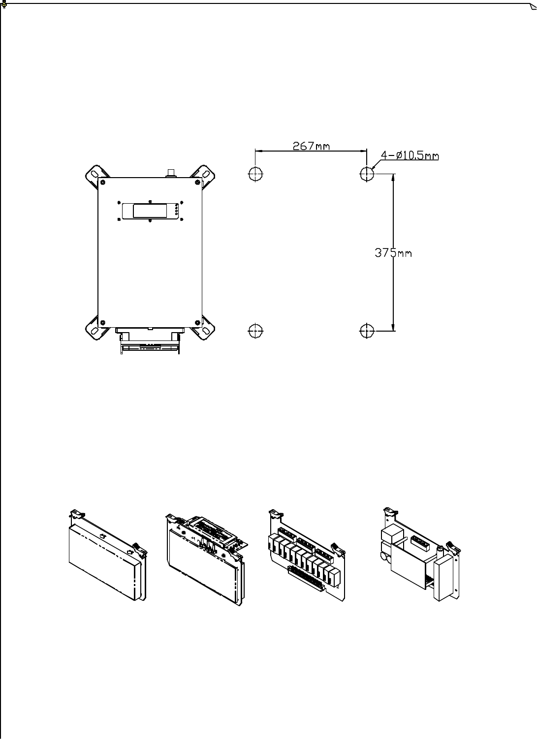
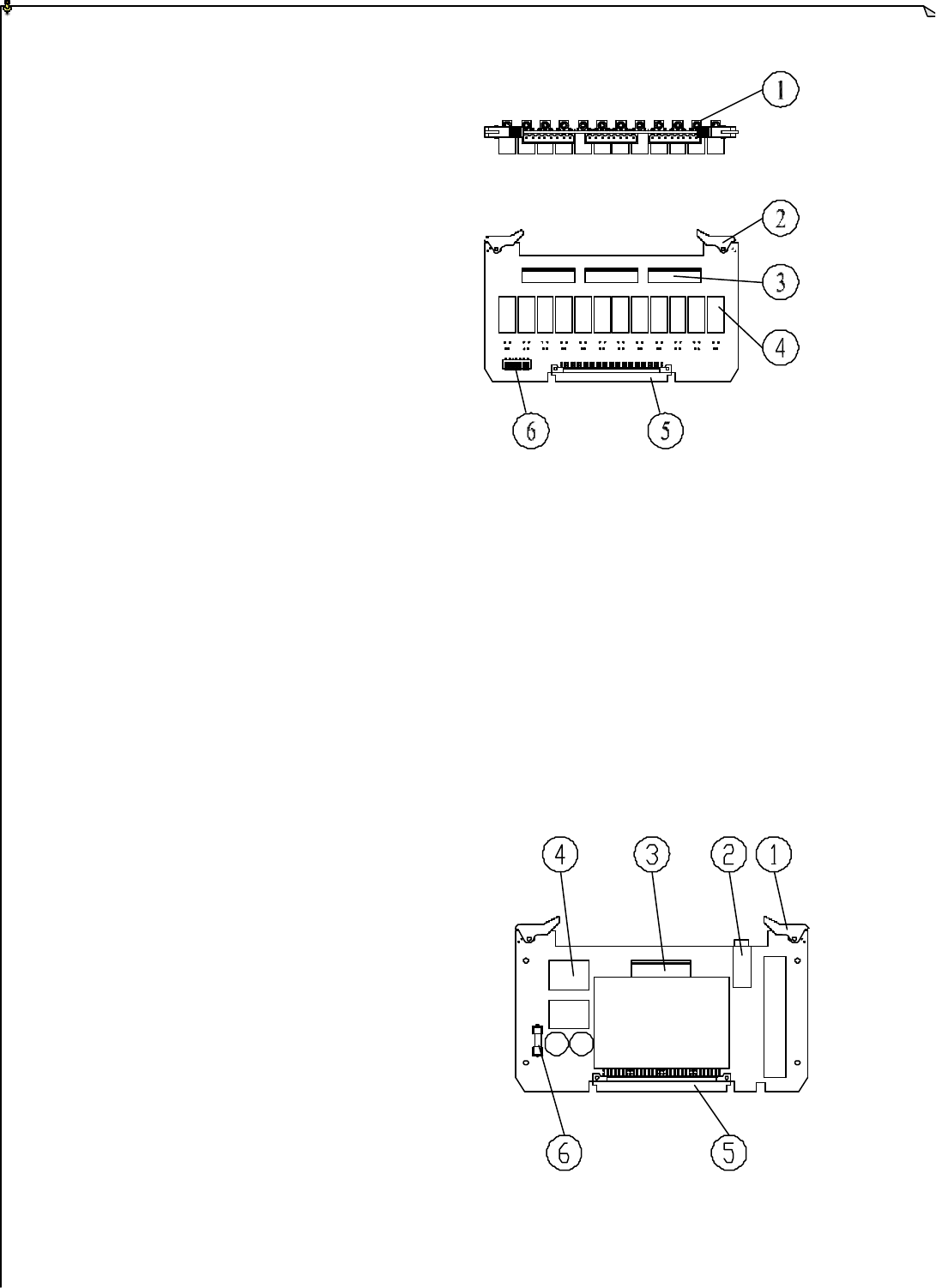
RX Module Card
1. RX Module Card Release Clip
2. RX-1 Antenna Port
3. RX-2 Antenna Port
4. RX module Shield Plate
5. RX Module Card-to-Motherboard
Connector
(Fig. 10)
Decoder Card
1. Power Display (LED-1)
2. SQ-1 Display (LED-2)
3. SQ-2 Display (LED-3)
4. Central CPU Status Display (LED-4)
5. Reserved Function Display (LED-5)
6. LED Panel
7. LCD Panel
8. RS 232 Serial Port
9. Dual Decoding CPU Status Display
(LED-6 and LED-7)
10. Function Settings Buttons
11. Decoder Shield Plate
12. Decoder Card-to-Motherboard
Connector
(Fig. 11)
12
Relay Card
1. LED Relay Display
2. Relay Card Release Clip
3. Relay Connector Port
4. Relays
5. Relay Card-to-Motherboard
Connector
6. Relay Card Position/Address
Dip-Switch (see note A).
(Fig. 12)
Note A: The relay card position/address dip-switch must be adjusted according to the
wiring diagram sheet located on the backside of the receiver cover plate.
Relay Card Position 1 address: 0000000
Relay Card Position 2 address: 0000001
Relay Card Position 3 address: 0000010
Relay Card Position 4 address: 0000011
Relay Card Position 5 address: 0000100
Power Supply Card
1. Power Supply Card Release Clip
2. Power Fuse
3. VAC Input / DVC Output Connector
4. MAIN Contact Relay
5. Power Supply Card-to-Motherboard
Connector
6. VDC Fuse
(Fig. 13)
13
6
6.
.
S
SY
YS
ST
TE
EM
M
S
SE
ET
TT
TI
IN
NG
GS
S
6
6.
.1
1
T
Tr
ra
an
ns
sm
mi
it
tt
te
er
r
I
ID
D
C
Co
od
de
e
S
Se
et
tt
ti
in
ng
gs
s
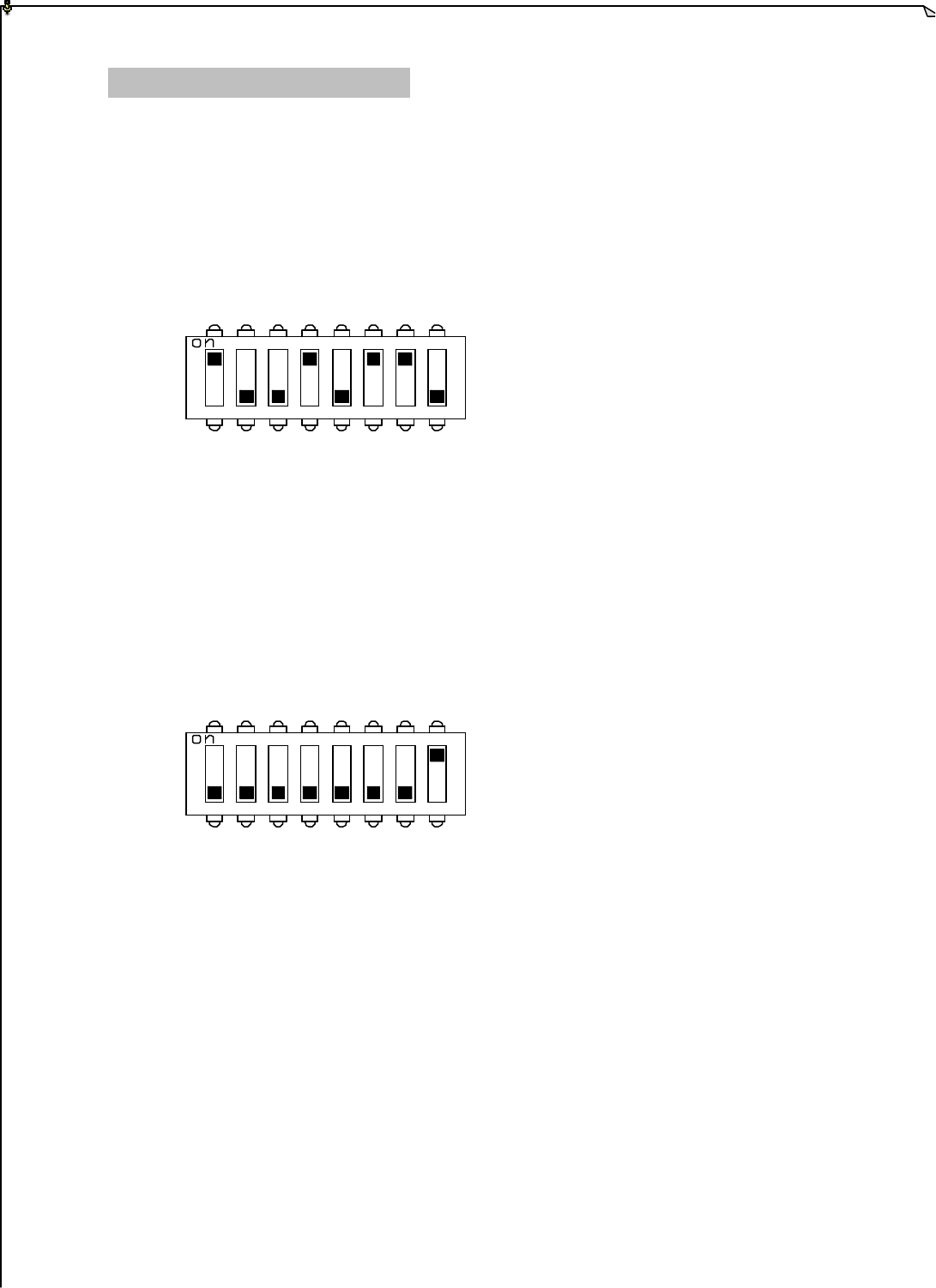
Id code settings are set via dip-switch located on the encoder board (refer to fig. 3
on page 8). For receiver ID code settings please refer to page 15 ~ 16.
Example : ID code 10010110
Top location : “1” Bottom location : “0”
6
6.
.2
2
T
Tr
ra
an
ns
sm
mi
it
tt
te
er
r
F
Fr
re
eq
qu
ue
en
nc
cy
y
C
Ch
ha
an
nn
ne
el
l
S
Se
et
tt
ti
in
ng
gs
s
Frequency channel settings are set via dip-switch located on the encoder board.
Please refer to fig. 3 on page 8 for dip-switch loc ation and frequency channel table
on page 15. For receiver frequency channel settings please refer to page 15 ~ 16.
Example: Frequency 433.075MHz / channel 01 (00000001)
Top location : “1” Bottom location : “0”
6
6.
.3
3
T
Tr
ra
an
ns
sm
mi
it
tt
te
er
r
S
Sp
pe
ec
ci
ia
al
l
F
Fu
un
nc
ct
ti
io
on
ns
s
S
Se
et
tt
ti
in
ng
gs
s
Special function settings can be programmed via IBM compatible computer with
special window based software or in-house designed programmer unit. Please
contact your dealer for more details.

14
6
6.
.4
4
F
Fr
re
eq
qu
ue
en
nc
cy
y
C
Ch
ha
an
nn
ne
el
l
T
Ta
ab
bl
le
e
Via dip-switch located inside the transmitter box and receiver LCD panel, the frequency
channel of the system can be altered.
FREQUENCY DIP-SWITCH SETTING CHANNEL
433.075 MHz 00000001 01
433.100 MHz 00000010 02
433.125 MHz 00000011 03
433.150 MHz 00000100 04
433.175 MHz 00000101 05
433.200 MHz 00000110 06
433.225 MHz 00000111 07
433.250 MHz 00001000 08
433.275 MHz 00001001 09
433.300 MHz 00001010 10
433.825 MHz 00001011 11
433.850 MHz 00001100 12
433.875 MHz 00001101 13
433.900 MHz 00001110 14
433.925 MHz 00001111 15
433.950 MHz 00010000 16
433.975 MHz 00010001 17
434.000 MHz 00010010 18
434.025 MHz 00010011 19
434.050 MHz 00010100 20
Note A: Other frequency channels are also available upon request.
15
FI'
0
00
000 00 0000 00 00 00 00 00 00 00 00 00 00
00 00
00 00
YS S
1:
F
5
I
2:5
P:1I:77 -1 1 1 1
I
6
6.
.5
5
R
Re
ec
ce
ei
iv
ve
er
r
L
LC
CD
D
O
Ou
ut
tl
li
in
ne
e
(Screen “1”)
(Screen “2”)
(Fig. 14)
1. RX–1 Signal Strength 9. ID Code – 1 (country code)
2. RX–2 Signal Strength 10. ID Code – 2 (system ID code)
3. System at Work 11. Decoder System – 1
4. Relay Activation Display 12. Decoder System – 2
“0” relay OFF; “1” relay ON 13. RX–1 Signal Strength
5. EXIT/DOWN (-) Button (PS1) 14. RX–2 Signal Strength
6. EDIT/UP (+) Button (PS2) 15. RX–1 Frequency Channel
7. MODE/ENTER Button (PS3) 16. RX–2 Frequency Channel
8. System Type (depending on system features)
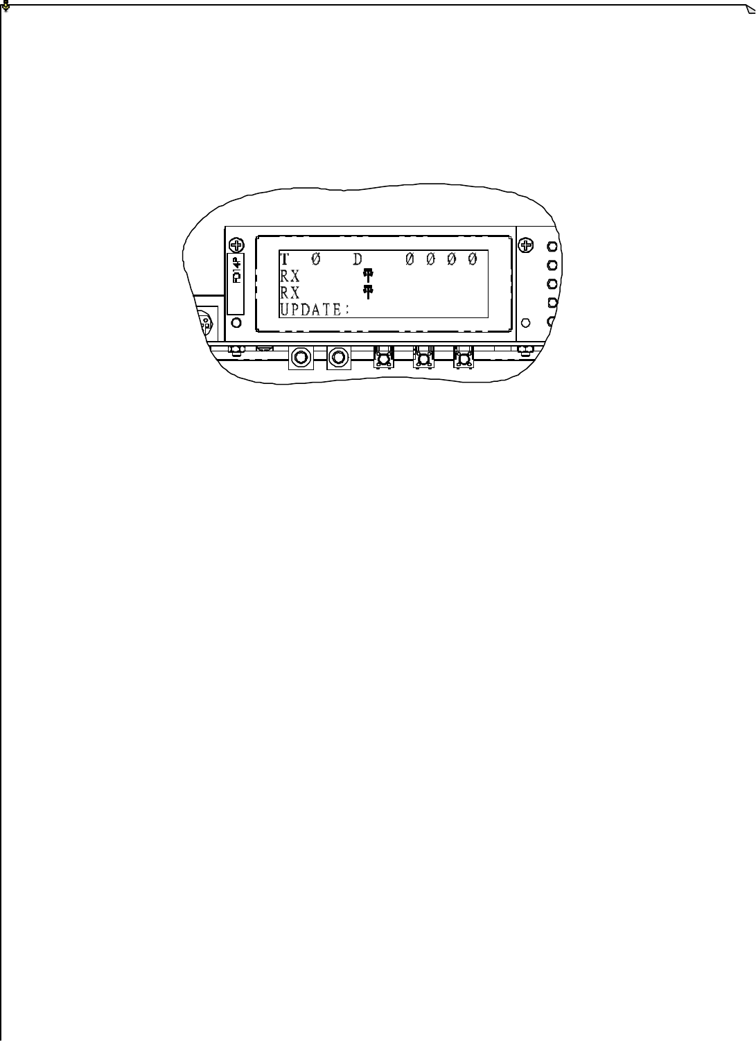
16
1:
2:
P:1I:77 -1111
__
__ _
___
_
_
6
6.
.6
6
R
Re
ec
ce
ei
iv
ve
er
r
I
ID
D
C
Co
od
de
e
a
an
nd
d
F
Fr
re
eq
qu
ue
en
nc
cy
y
S
Se
et
tt
ti
in
ng
gs
s
(Screen “3”)
1) To enter into screen-2, press MODE/ENTER button one time.
2) To enter into Screen-3, press EDIT/UP button for up to 5 seconds.
3) TP (System type) and Country code can not be changed.
4) Press EXIT/DOWN (-) and EDIT/UP (+) to change values of the ID code.
5) Press MODE/ENTER button to proceed to the RX-1 setting column.
6) Press EXIT/DOWN (-) and EDIT/UP (+) to change frequency channel of the
RX1.
7) Press MODE/ENTER button to proceed to the RX-2 setting column.
8) Press EXIT/DOWN (-) and EDIT/UP (+) to change frequency channel of the
RX2.
9) Press MODE/ENTER button to proceed to the UPDATE setting column.
10) Press EDIT/UP to input “YES” (save changes).
11) Press EXIT/DOWN to input “NO” (cancel changes).
Note: If new values are not inputted within 25 seconds, the system will exit the
setup screen (screen 3) and returned to screen 1.
17
7
7.
.
R
RE
EC
CE
EI
IV
VE
ER
R
S
SY
YS
ST
TE
EM
M
S
ST
TA
AT
TU
US
S
D
DI
IS
SP
PL
LA
AY
YS
S
(Fig 15)
1. Receiver Power Display 4. Central CPU Status Display
2. SQ-1 (RX-1) Status Display 5. LCD System Information Display
3. SQ-2 (RX-2) Status Display
Receiver Power Display
Should be lid at all time during power “on”.
SQ-1 and SQ-2 Status Displays
Lights “on” Transmitted Signals Received.
Lights “off” No Transmitted Signals.
Blinking Lights Strong Outside Radio Interference.
Dual Decoding CPU Status Display
(refer to Fig. 11 on page 11)
Lights “on” 0.1 second / “off” 1.0 second Decoders on Standby.
Lights “on” 0.1 second / “off” 0.1 second Decoding in Process.
Central CPU Status Display
LED INDICATION REASON
Slow Blinks (Green) Standby
Fast Blinks (Green) Transmitted signals received
Fast Blinks (Red) Motion contact relays or the MAIN contact relays are
locked
3 Fast Blinks (Red) PLL RX module defected
4 Fast Blinks (Red) EEPROM error
5 Fast Blinks (Red) Incorrect transmitted ID code
6 Fast Blinks (Red) Incorrect system type
18
YS S
1:
F
5
I
2:5
P:1I:77 -1 1 1 1
I
Other System Status Display Feature
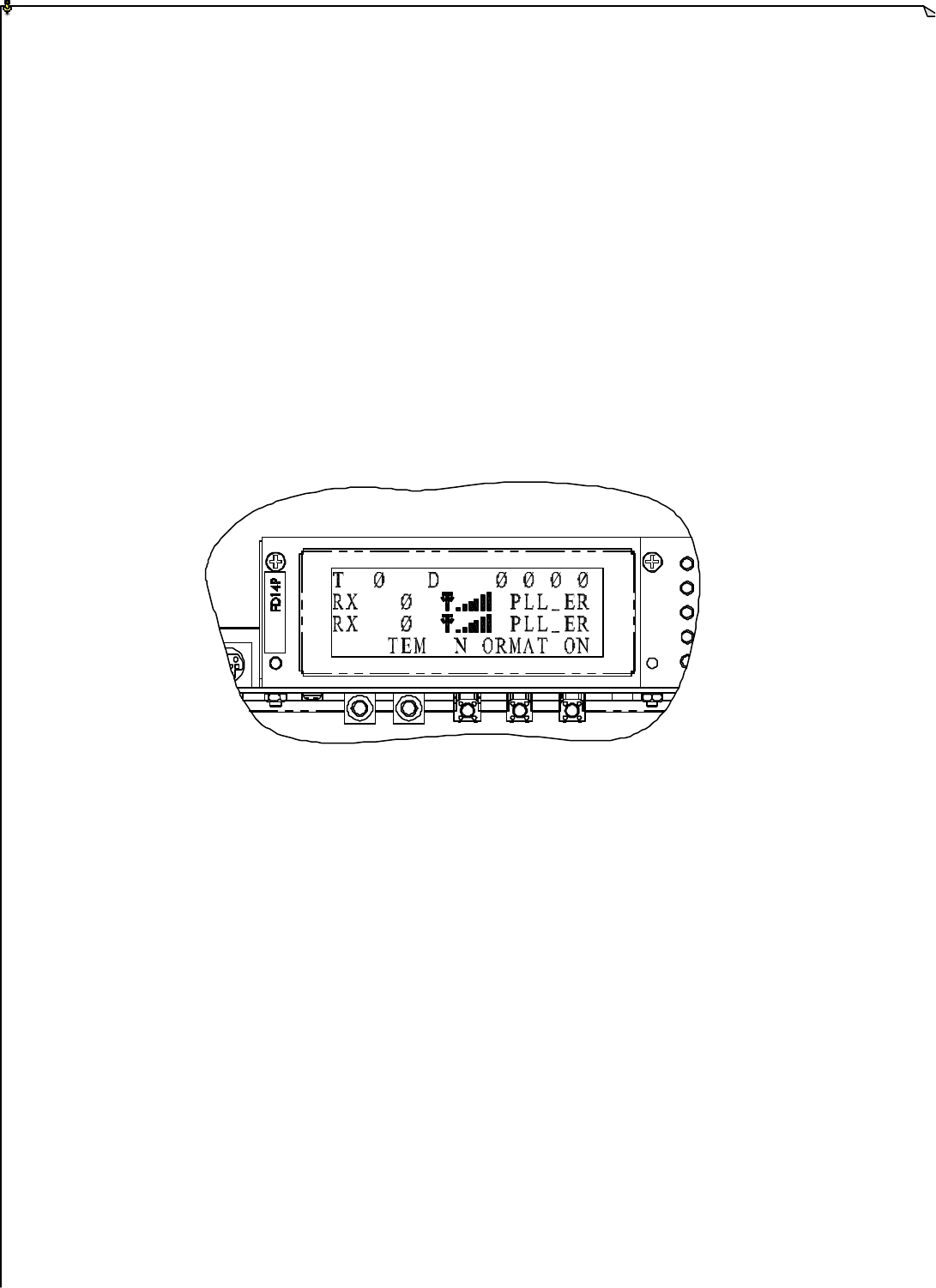
Some of the system status indications described on page 17 are also displayed on the
receiver LCD screen for easy readout (on screen 2).
1) ID_ER Incorrect transmitted ID code
2) MAIN_ER Defected MAIN contact relay or relays
3) PLL_ER Defected PLL RX module
4) WORK Transmitted signals received and decoded
5) SEARCH System on standby
6) SCAN System scanning for new frequency channel

19
8
8.
.
R
RE
EC
CE
EI
IV
VE
ER
R
I
IN
NS
ST
TA
AL
LL
LA
AT
TI
IO
ON
N
8
8.
.1
1
P
Pr
re
ep
pa
ar
ra
at
ti
io
on
n
1) Flat Head Screwdriver (- )
2) Phillips Head Screwdriver (+)
3) Multi-Meters
4) 14 mm Wrench X 2
5) Power Drill with 10.5 ~ 11mm Drill-Bit
6) Output Cables
1. Ensure receiver is not set to the same channel and ID code as any other units in
operation at the same facility within 300 meters/900 feet.
2. Prior to installation, make sure that the crane system itself is working properly.
3. Use the multi-meter to check the voltage source available and ensure receiver voltage
setting is correct for this voltage.
4. Prior to installation, switch off the main power source to the equipment.
8
8.
.2
2
S
St
te
ep
p
B
By
y
S
St
te
ep
p
I
In
ns
st
ta
al
ll
la
at
ti
io
on
n
1. Select a suitable location to mount the receiver.
2. The location selected should have the antenna visible from all areas where the
transmitter is to be used.
3. The location selected should not be exposed to high levels of electrical noise.
4. Ensure the selected location has adequate space to accommodate the receiver enclosure.
5. The distance between the antenna and the control panel should be as far apart as
possible.
5. Drill four holes on the control panel (10.5mm).
6. Tightened all screws provided.
7. For system wiring, please refer to the wiring diagram located on the last page of this
manual and on the backside of the receiver cover plate.
8. Ensure all wiring is correct and safely secured and all screws are fastened.

20
(Fig. 16)
8
8.
.3
3
S
Sy
ys
st
te
em
m
T
Te
es
st
ti
in
ng
g
1. Connect the power source to the receiver and test the operation of each function to
ensure it operates in the same manner as the pendant controller.
2. Ensure the MAIN contact relay can be properly controlled by the remote control.
3. Ensure the limit switches on the crane that limit all travels are working properly.
4. Ensure the pendant controller is located in a safe location where it would not interfere
with remote operation.
21
9
9.
.
O
OP
PE
ER
RA
AT
TI
IN
NG
G
I
IN
NS
ST
TR
RU
UC
CT
TI
IO
ON
N
9
9.
.1
1
P
Po
ow
we
er
r
“
“O
ON
N”
”
t
th
he
e
S
Sy
ys
st
te
em
m
1. Insert the power key switch into the key slot located on the right side of the
transmitter unit.
2. Push in the key and turn the key clockwise (forward) to “1” position.
“1” “ON” “0” “OFF”
3. Make sure both joysticks are in their neutral (0-speed) position.
4. Make sure that the red emergency stop button (EMS) is in its elevated position.
5. To activate the receiver MAIN, press and hold the “START” pushbutton located on
the right side of the transmitter box for 2.0 seconds.
6. After system start up, if the operator did not give any command by pressing any
pushbuttons or moving the joysticks to a non-neutral position, the transmitter unit
will go into sleep mode with receiver MAIN contact relays temporarily deactivated.
To resume operation, just press any pushbutton or move the joysticks again to
re-activate the system.
7. After 1 hours of system non-usage, the entire system will be deactivated.
8. If the frequency channel of the transmitter unit is changed via a dip-switch inside
the transmitter box (refer to page 13), you must then also change the frequency
channel in the receiver box (refer to page 15~16). If the receiver unit is equipped
with an auto-scanning feature, after changing the frequency channel of the
transmitter unit, you must then press START button for up to 20 seconds after
transmitter unit power “on” in order for the auto-scanning receiver to identify the
newly selected channel.
9
9.
.2
2
T
Tr
ra
an
ns
sm
mi
it
tt
te
er
r
S
Sy
ys
st
te
em
m
S
St
ta
at
tu
us
s
D
Di
is
sp
pl
la
ay
ys
s
(Fig. 17)
1. Battery Power LED Display
2. Transmitting Status LED Display
1 2

22
Transmitter Battery Power LED Display
POWER DISPLAY REASON
Constant Green Battery level normal
Slow Blinking Red Low battery level (1st warning)
Fast Blinking Red Low battery level (2nd warning)
Transmitter unit will stop transmitting at anytime
Constant Red Low battery level (3rd warning)
Transmitter and receiver unit deactivation
Transmitter Status LED Display
STATUS DISPLAY REASON
No Light Displayed No transmitting signals outputted
Slow Blinks (Green) Neutral position signals transmitted (refer to note A)
Fast Blinks (Green) Active command signals transmitted
Constant Red Light Jammed or defected pushbutton or joysticks at system Power
“on”
Fast Blinks (Red) The contact point currently in use is ok (refer to note B)
3 Fast Blinks (Red) PLL TX module defected
4 Fast Blinks (Red) EEPROM error
Note A: If equipment is equipped with Selector switches, active commands are
transmitted at all time during transmitter power “on”.
Note B: When there is defected or jammed contact (pushbutton and joystick), the
status LED will display a constant red light without flashes. To find out
which contact point is defected or jammed, activate each pushbutton and
joystick by pressing and moving each pushbutton and joystick speed one step
at a time. Activating a non-defected pushbutton or joystick contact will
display a fast blinking red light on the status LED. This fast blinking
red light is to show the operator that the contact point currently activating is
not defected. On the other hand, if the defected or jammed contact point is
activated, the status LED will remain constant red with out any flashes. The
main purpose of function is to let the operator realize which contact point is
not working properly.

23
1
10
0.
.B
BA
AT
TT
TE
ER
RY
Y
C
CH
HA
AR
RG
GI
IN
NG
G
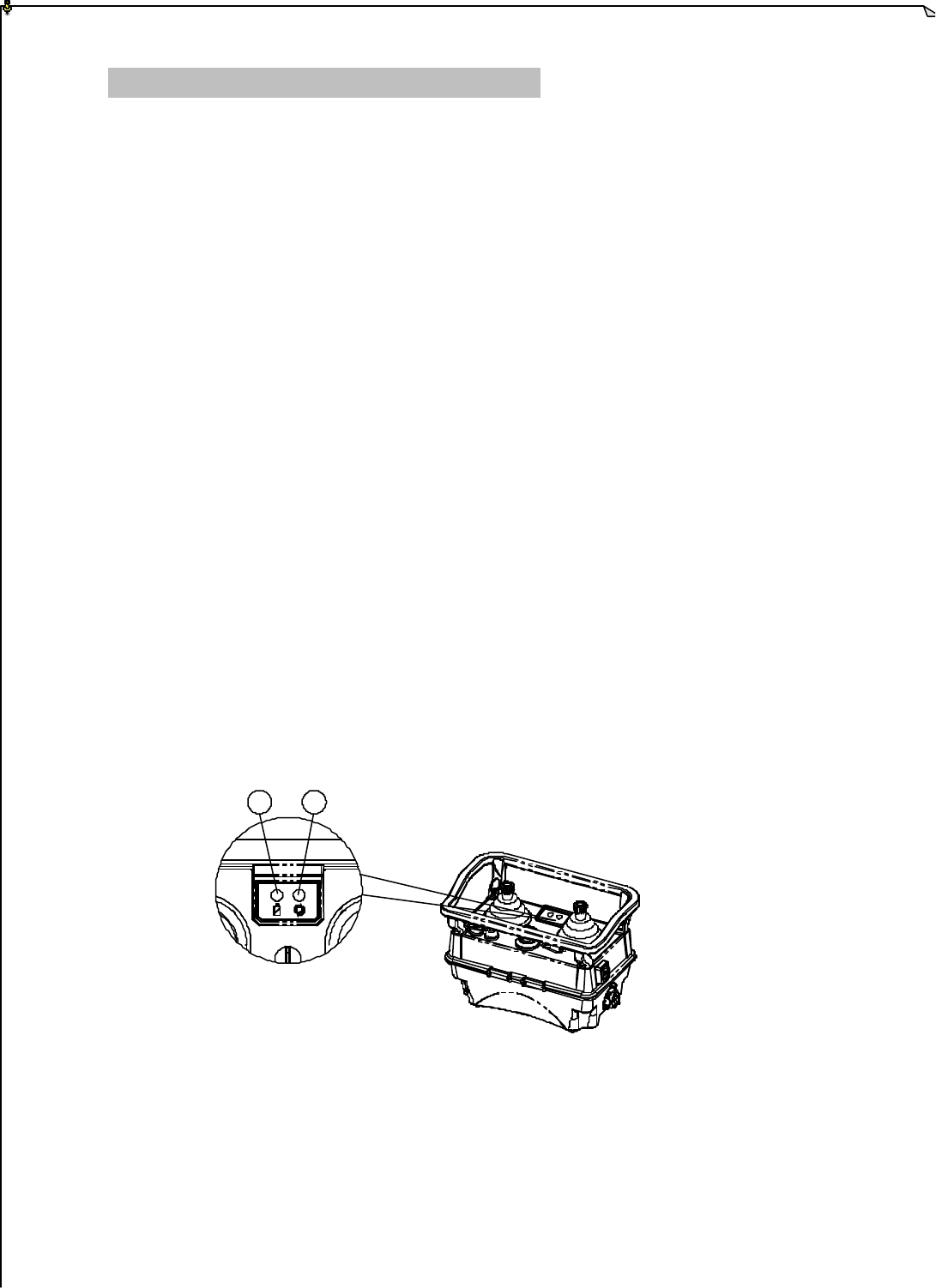
1. Plug in the power cord and the power indicator will light up.
2. When a battery pack is inserted, the green charging light will blink to indicate charging
is taking place at the current moment.
3. If discharging of battery pack is desired (strongly recommended), press the
“DISCHARGE” button. At discharging mode, the green blinking light will now
turned into a constant red light indicating that the battery pack is now being discharged.
If you want to cancel the discharge, just press “DISCHARGE” button again.
4. When discharging is completed, it will automatically switch to the charging mode
where the green blinking light will appear again.
5. The charging time for a battery pack is approximately 3~6 hours (600mA).
6. When charging is completed, a constant green light will appear to indicate that the
battery pack is fully charged.
7. When the battery pack is at 90% charged state, trickle charging will take over to ensure
the longevity of the battery pack and as well as to ensure the battery pack is 100%
charged.
8. When the battery pack’s temperature exceeds 50, the charger will go into protective
mode and charging will be discontinued.
9. To prolong the life of the battery pack, it is recommended that the battery pack be fully
discharged prior to every re-charging.

24
1
11
1.
.S
SY
YS
ST
TE
EM
M
S
SP
PE
EC
CI
IF
FI
IC
CA
AT
TI
IO
ON
N
1
11
1.
.1
1
T
Tr
ra
an
ns
sm
mi
it
tt
te
er
r
U
Un
ni
it
t
Frequency Range : PLL 433 MHz
Transmitting Range: : 100 meters / 300 feet *
Continuous Operating Time : 8 Hours (600mA) / 16 Hours (1400mA)
Security ID Code : 65,536 sets (16 + 1 bit)
Channel Spacing : 25KHz
Hamming Distance : 6
Frequency Control : Quartz Crystals + PLL
Frequency Drift : < 3ppm @ -20 ~ 70
Frequency Deviation : < 1ppm @ 25
Spurious Emission : > 60dBc
Transmitting Power : 0.1mW
Emission : F1D
Antenna Impedance : 50 ohms
Enclosure : IP-65
Source Voltage : 7.2 V (600mA) or 7.2 V (1400mA)
Current Drain : ~80mA
Operating Temp. : -20 ~ 70
Dimension : 247mm X 154mm X 182mm
Weight : 1,600g (with battery pack)
* Longer transmitting-receiving range available upon request.

25
1
11
1.
.2
2
R
Re
ec
ce
ei
iv
ve
er
r
U
Un
ni
it
t
Frequency Range : PLL 433 MHz
Channel Spacing : 25KHz
Hamming Distance : 6
Frequency Control : Quartz Crystals + PLL
Frequency Drift : < 3ppm @ -20 ~ 70
Frequency Deviation : 1ppm @ 25
Sensitivity : < 0.18ìV
Decoding : FSK
Antenna Impedance : 50 ohms
Data Decoder Reference : Quartz Crystals
Responding Time : 100mS ~ 300mS
Enclosure : IP-65
Source Voltage : 100 ~ 240VAC @ 50/60 Hz.*
Power Consumption : 36VA
Operating Temp. : -20 ~ 70
Output Contact Rating : 250V @ 10A
Dimension : 417mm X 309mm X 167mm
Weight : 8,800g
* Other types of source voltage are also available upon request.