Food Automation Service Techniques XWIRE-GATEWAY Food quality and supply chain monitor equipment User Manual Letter Size
Food Automation - Service Techniques, Inc. Food quality and supply chain monitor equipment Letter Size
User Manual

Installation Guide
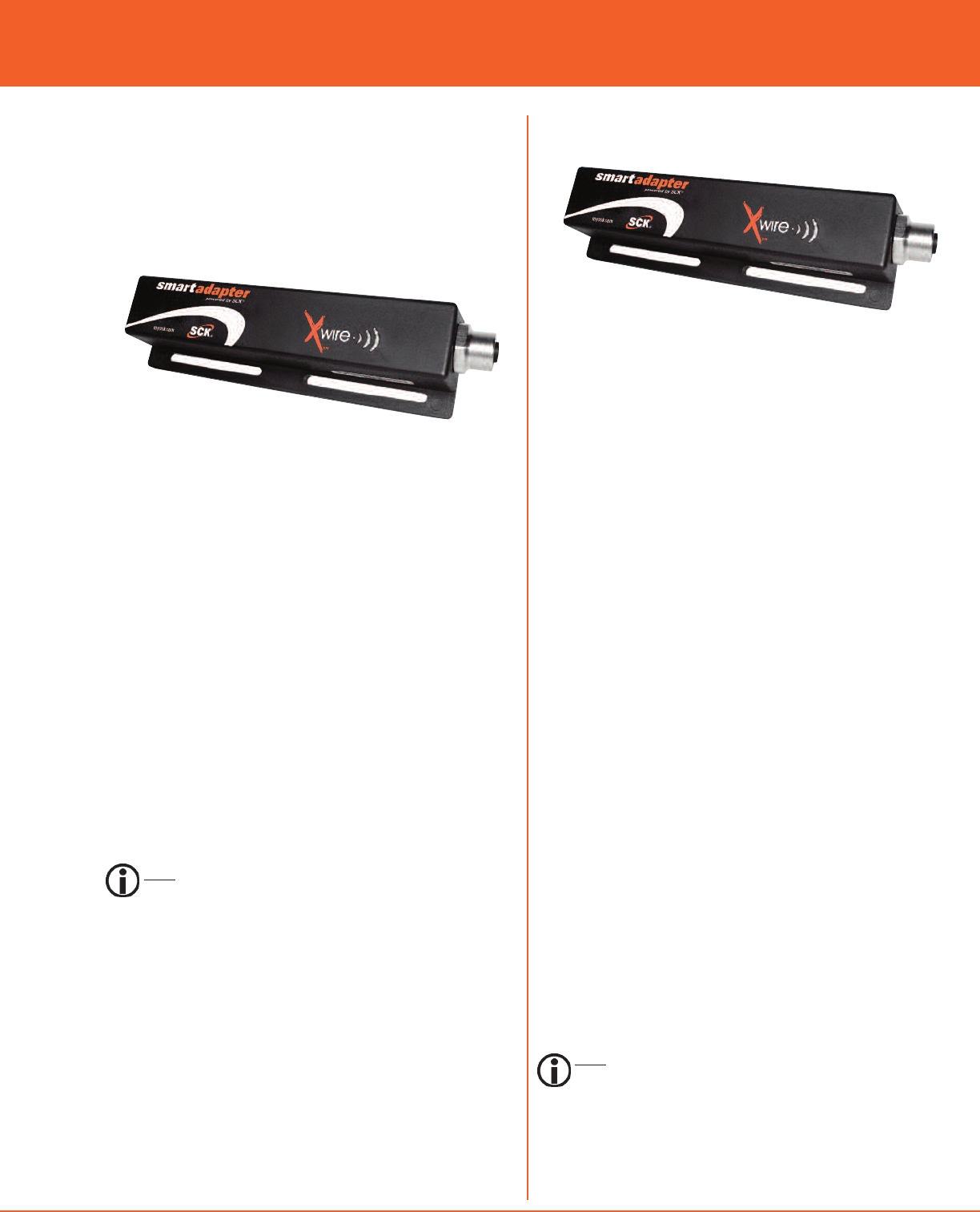
XwireTM Universal SmartAdapter for
Communications-Enabled Appliances
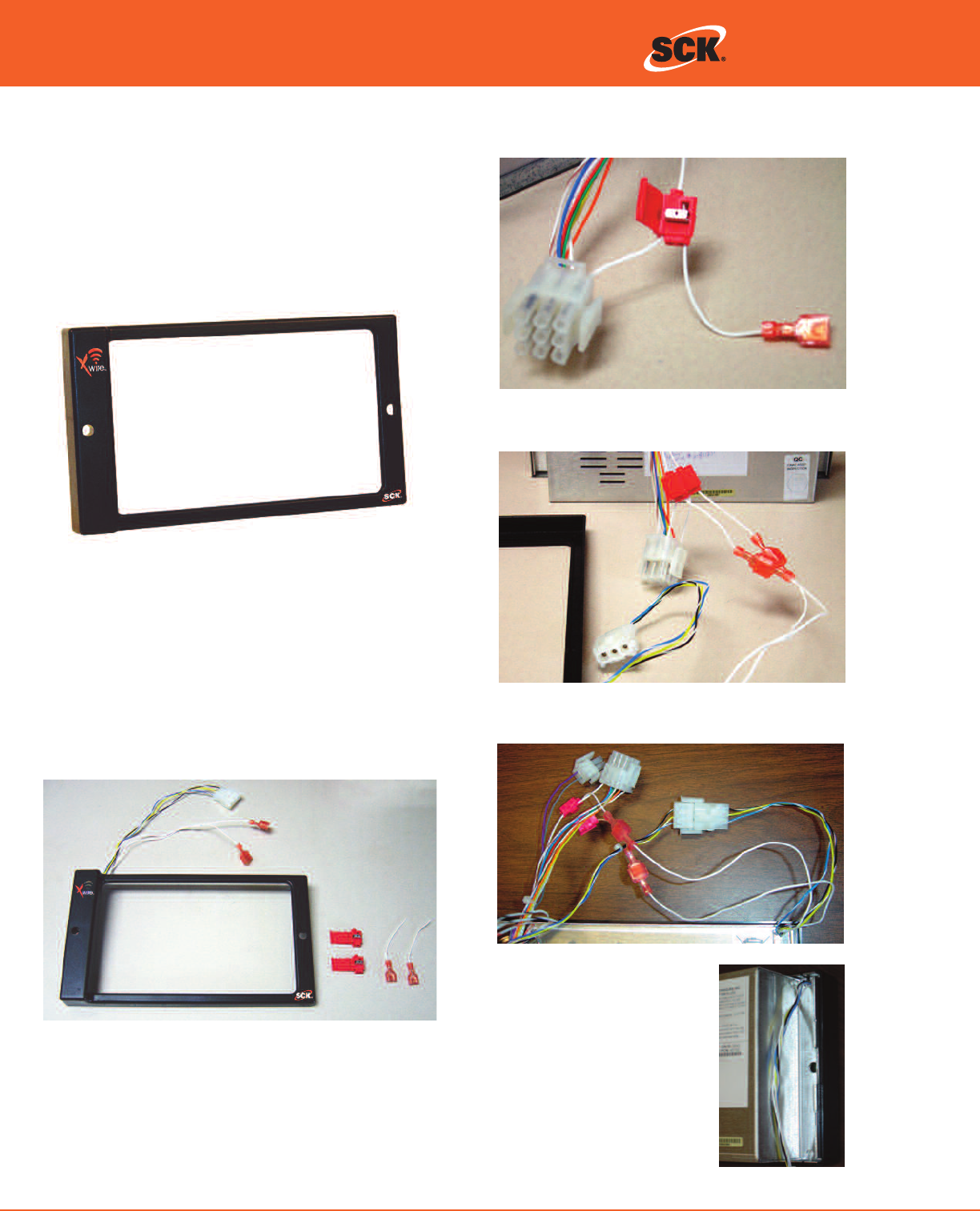
XwireTM SmartBezel Adapter for Process Controllers
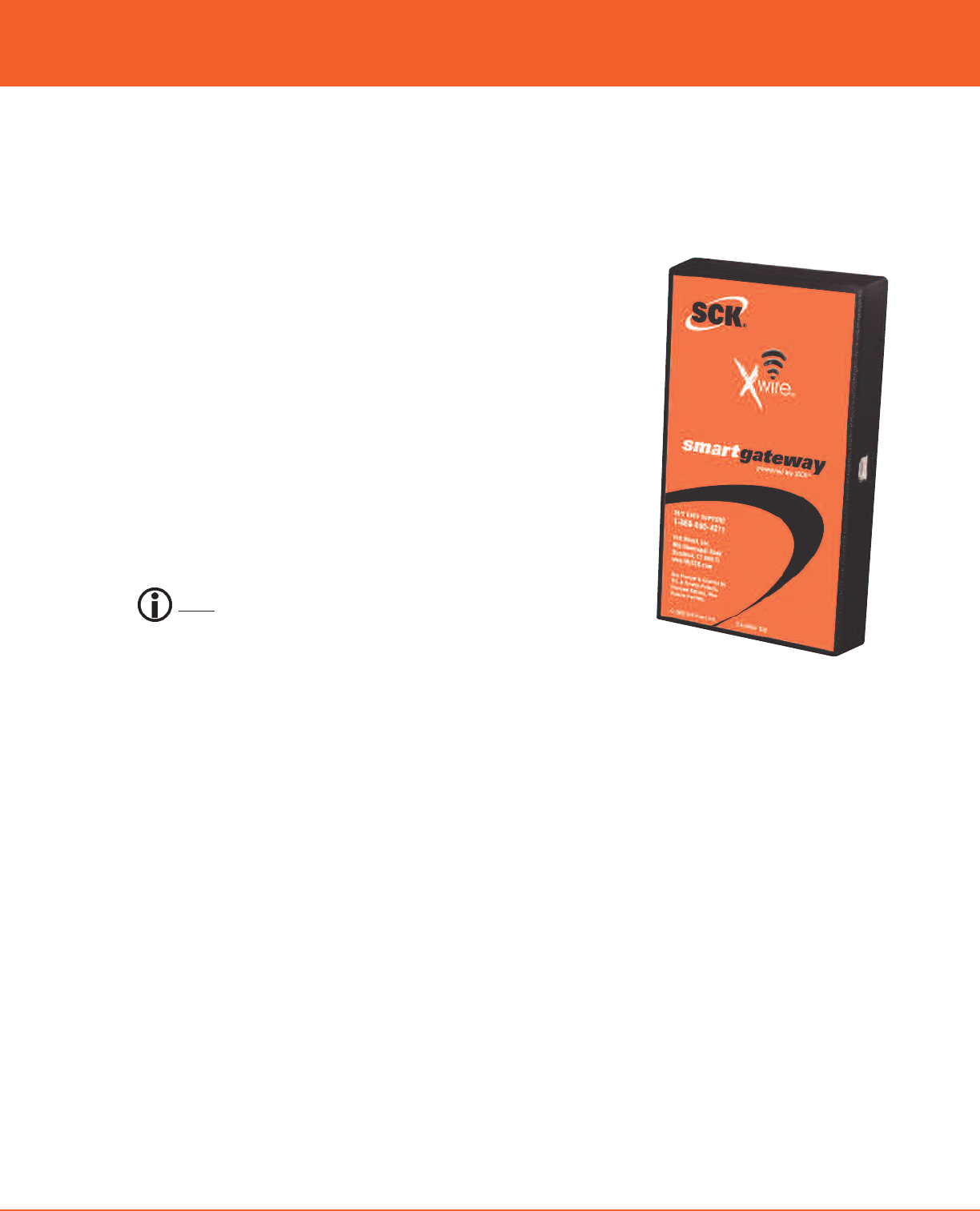
XwireTM SmartGateway PC Adapter
SmartAdapter
SmartBezel
SmartGateway
24/7 Toll-Free Technical Support
1-866-840-4271
(from the U.S., Canada and the Caribbean)
Direct, Inc.
www.MySCK.com
SAVE these instructions
for future reference.

2© 2008 SCK Direct, Inc. 229-51316 Rev F www.MySCK.com
XwireTM Direct, Inc.
NOTICES
SCK Direct, Inc. is not liable for any use of product not in accor-
dance with SCK Direct, Inc.’s installation and operation
instructions.
BEFORE USING THIS EQUIPMENT, OR FOR ANY QUESTIONS ON
THE OPERATION OF THE APPLIANCE, CONSULT AND FOLLOW ALL
INSTRUCTIONS AND SAFETY WARNINGS FOUND IN THE APPLI-
ANCE OPERATOR’S MANUAL SUPPLIED FROM THE
MANUFACTURER OF THE APPLIANCE.
CLEANING
Using a clean damp cloth, wipe down the products when neces-
sary using a commercial quality foodservice-approved detergent.
DO NOT IMMERSE.
NEVER use chemical or abrasive cleaners on SCK products.
TOOLS REQUIRED FOR INSTALLATION
Flat screwdriver (for SmartBezel)
Pliers (for SmartBezel)
Phillips screwdriver (for SmartAdapter)
Drill bit: 3/16” if using anchor. #50 if installing into metal (for
SmartAdapter)
Changes or modifications not expressly
approved by SCK Direct, Inc. could void the
manufacturer’s warranty and the user's
authority to operate the equipment.
NOTE: This equipment has been tested and found to comply with
the limits for a Class B digital device, pursuant to Part 15 of the FCC
Rules. These limits are designed to provide reasonable protection
against harmful interference in a residential installation. This
equipment generates, uses and can radiate radio frequency ener-
gy and, if not installed and used in accordance with the
instructions, may cause harmful interference to radio communica-
tions. However, there is no guarantee that interference will not
occur in a particular installation. If this equipment does cause
harmful interference to radio or television reception, which can be
determined by turning the equipment off and on, the user is
encouraged to try to correct the interference by one or more of
the following measures:
Reorient or relocate the receiving antenna.
Increase the separation between the equipment and
receiver.
Connect the equipment into an outlet on a circuit different
from that to which the receiver is connected.
Consult the dealer for help.
TABLE OF CONTENTS
Installation: Wireless SmartGateway Adapter . . . . . . . . . . . . . .3
Installation: SmartBezel Adapter
for FAST VC-210 & FAST EM-99 Controllers . . . . . . . . .4
Installation: Universal SmartAdapter
forFASTTRACKERTimers..........................5
Installation: Universal SmartAdapter
forFryers&Ovens.................................5
Light Bar and LED Status Charts . . . . . . . . . . . . . . . . . . . . . . . . . . .6
Troubleshooting..........................................7
ChangingtheDefaultPANID .............................7
3
© 2008 SCK Direct, Inc. 229-51316 Rev F www.MySCK.com
installation guide
Xwire Wireless
SmartGateway Adapter
REQUIRED PARTS
(A) Xwire Wireless SmartGateway Adapter
SCK Part No. 231-60207-01
(B) USB Cable, 5M
SCK Part No. 141-15734
INSTALLATION
1. Connect USB cable to the communication port on the SmartGateway.
2. Power off the PC and connect the SmartGateway to an available USB port
using the USB cable.
NOTE: It’s important to power down for proper configuration.
3. Verify the LED sequence on the SmartGateway is correct per your applica-
tion by referring to the charts on page 6.
STEP 1
The SmartGateway should be installed first.
4© 2008 SCK Direct, Inc. 229-51316 Rev F www.MySCK.com
XwireTM Direct, Inc.
Xwire SmartBezel Adapter for
FAST VC-210 & FAST EM-99
CONTROLLERS
REQUIRED PARTS
(1) Xwire SmartBezel Adapter
SCK Part No. 231-60206-01
(2) Self-tapping Connectors (included)
SCK Part No. 141-51026
Qty. 2
INSTALLATION
1. Locate wires numbered 1 and 3 in the 9-pin connector on
the FAST VC-210 or FAST EM-99 controllers.
2. Clamp self-tapping connector to these wires to provide a
24VAC output for the SmartBezel.
3. Connect the two spade terminals to the pair coming from
the SmartBezel.
4. Connect the 3-pin Molex connector on the SmartBezel to
the 3-pin Molex on the controller.
5. Position the SmartBezel onto the
front of the FAST Controller.
Carefully place the five SmartBezel
wires into the channel on the
FAST Controller.
6. Install the FAST Controller on the
fryer and verify the LED sequence
is correct per your application by
referring to the charts on page 6.
The FAST Controller is now ready to be used as an SCK Xwire
wireless device.
STEP 2
The SmartBezel Adapter
5
© 2008 SCK Direct, Inc. 229-51316 Rev F www.MySCK.com
installation guide
REQUIRED PARTS
(A) Xwire Universal SmartAdapter for FAST TRACKER Timers
SCK Part No. 231-60208-01
(B) Harness for Xwire Universal SmartAdapter
i. 12” SCK Part No. 222-50700-01
ii. 48” SCK Part No. 222-50700-02
(C) Mounting Kit.
SCK Part No. 213-50761-01
If something is missing, please call 1-866-840-4271 (8:00 a.m. -
5:00 p.m. EST).
INSTALLATION
1. Connect harness to the communication port on top of the
TRACKER Timer.
2. Connect other end of harness to the Xwire Universal
SmartAdapter. Mount the SmartAdapter using the supplied
Velcro.
Note: Mount in a place the SCK Xwire SmartGateway will
receive a signal.
3. Verify the LED sequence on the SmartAdapter is correct per
your application by referring to the charts on page 6.
Xwire Universal SmartAdapter for
(FAST.)® TRACKERTM TIMERS
The TRACKER Timer is now ready to be used as an SCK Xwire
wireless device.
REQUIRED PARTS
(A) Xwire Universal SmartAdapter for Fryers and Ovens
SCK Part No. 231-60208-01
(B) Self-tapping Connectors (included)
SCK Part No. 141-51026
Qty. 2
(C) Harness: Choose One
i. SCK Part No. 222-50702-01
ii. SCK Part No. 222-50701-01
iii. SCK Part No. 222-50701-02
(D) Velcro Brand Fastener
If something is missing, please call 1-866-840-4271 (8:00 a.m. -
5:00 p.m. EST).
INSTALLATION
1. Pull the SCK-enabled Controller away from appliance.
Locate wires numbered 1 and 3 in either the 15-pin connec-
tor or the 9-pin connector (depending on the Controller) on
the back of the Controller. These are your 24VAC.
2. Clamp the self-tapping connector to these wires to provide
a 24VAC output to the SmartAdapter and also the two pig-
tail wires that are supplied.
3. Connect the two pigtail wire terminals to the pair coming
from the harness.
4. Connect the 3- or 4-pin Molex (depending on Controller)
from the harness to the controller.
5. Drill a hole in the back of the appliance to feed harness
through.
6. Connect the harness to the SmartAdapter and mount using
Velcro tape that is supplied.
Note: Mount in a place the SCK Xwire SmartGateway will
receive a signal.
7. Re-mount the SCK-enabled Controller back into the appli-
ance and verify the LED sequence on the SmartAdapter
indicator is correct by referring to the charts on page 6.
Xwire Universal SmartAdapter for
FRYERS AND OVENS
The SCK-enabled Controller is now ready to be used as an
SCK Xwire wireless device.
STEP 3
The Universal SmartAdapters
6© 2008 SCK Direct, Inc. 229-51316 Rev F www.MySCK.com
XwireTM Direct, Inc.
LED Color LED Blink Rate Description
ORANGE 2 sec ON,
2 sec OFF
Device cannot communi-
cate with the SCK device
after already connecting to
the wireless network.
ORANGE Very Fast Device is initializing.
GREEN Solid On
Device has found a
SmartGateway and is now
connected to the network.
GREEN Very Fast
Device is waiting for a
reply for data sent to
another device.
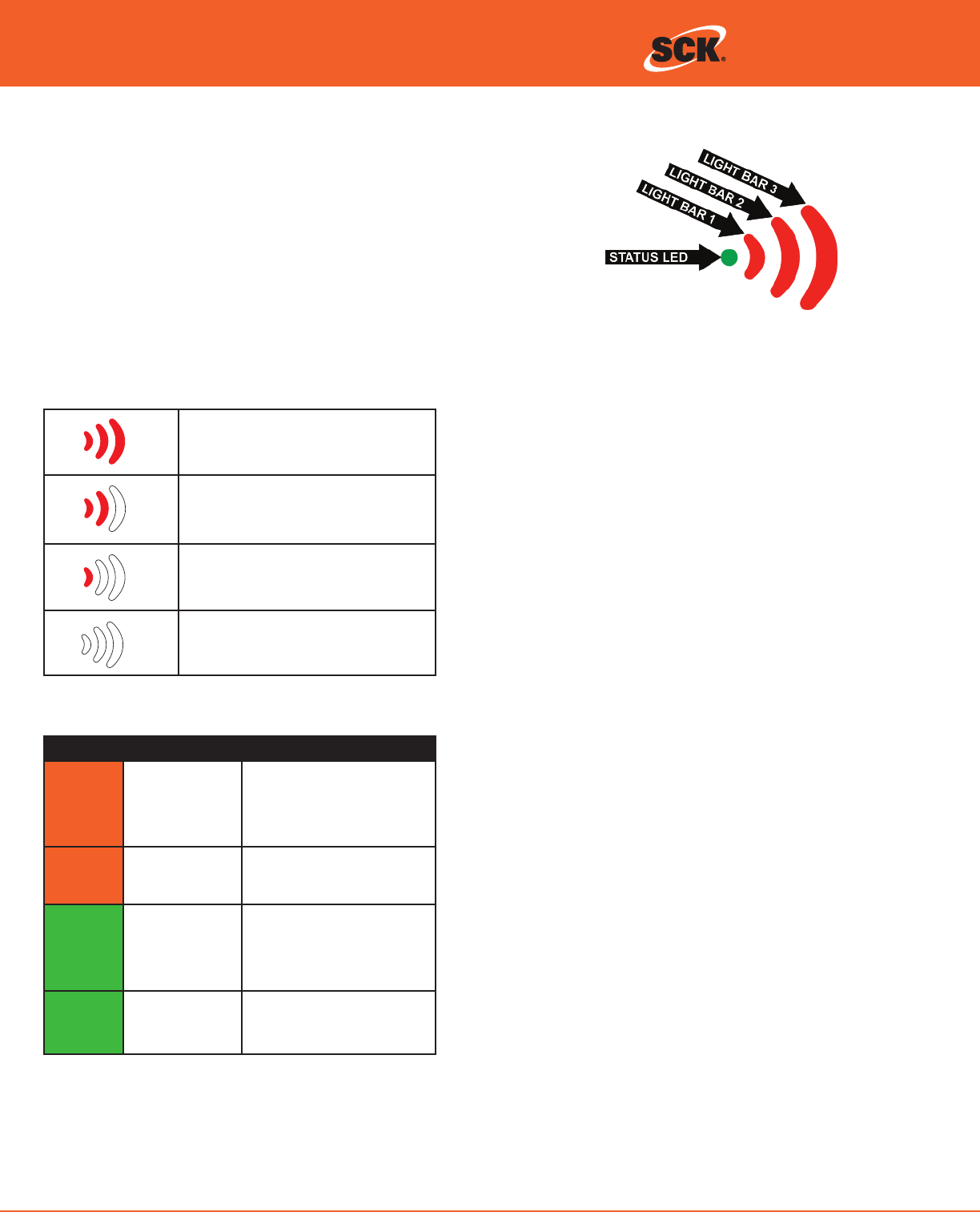
STRONG
All light bars are lit RED.
GOOD
At least two light bars are lit RED.
WEAK
Only one light bar is lit RED.
NONE
No light bars are lit RED.
STATUS LED CHART
SIGNAL STRENGTH INDICATORS LIGHT BARS
The SCK Xwire status indicator consists of three colors (Green, Red and
Orange) to visually indicate transmission strength and operating status to
the operator.
See the charts below for details.
Light Bars and Status LED
How Do I Know if It’s Working?
Under normal operating conditions, the status LED will be solid
green and all or some of the signal strength LEDs (light bars) will
be lit depending on signal strength. In most cases, you’ll see the
green status LED lit solid while the signal strength light bars
change from time to time.
7
© 2008 SCK Direct, Inc. 229-51316 Rev F www.MySCK.com
installation guide
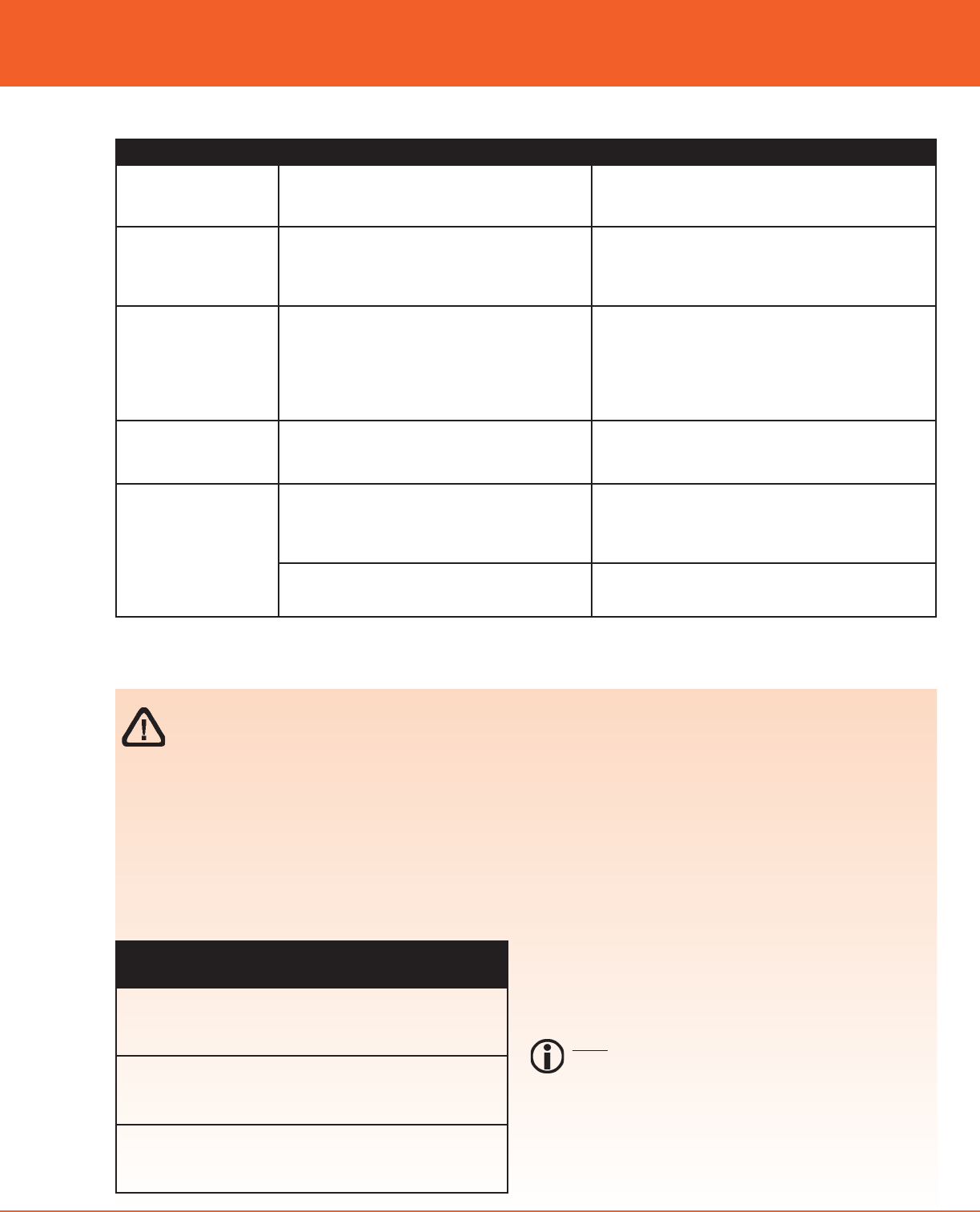
TROUBLESHOOTING / LED CODES
LED Action Description Solution
All LEDs blink on and
off simultaneously
every 500ms.
Device has detected a multiple SCK address
conflict and is waiting for resolution (cur-
rently participating as address 30)
1. Verify that all enabled controls are set to a
different SCK address.
All LEDs blink in two
short bursts followed
by one second of off
time.
The device is connected to a wireless net-
work but not to an SCK-enabled control.
1. Make sure device is SCK compatible.
2. Make sure communication port is connected.
3. Check SCK wiring.
4. Install it on a known working appliance.
All LEDs strobe. Device is searching for a SmartGateway. 1. Verify the SmartGateway is turned ON.
2. Install the Xwire device closer to the
SmartGateway.
3. A SmartRepeater may need to be added to
extend the range. Contact your SCK Sales
Representative.
Status LED flashes
green/orange continu-
ously.
The radio on the SmartGateway has been
turned OFF.
1. Contact your local Helpdesk, or SCK
Support at 1-866-840-4271
Orange LED blinks ON
for 2 seconds, then
OFF for 2 seconds.
Device is attempting to resolve an SCK
address conflict by changing to address 30,
but there is already another device on the
SCK network using address 30.
1. Verify that all enabled controls are set to a
different SCK address.
Device cannot communicate with the radio. 1. Try cycling power to the unit OFF, then ON.
2. Contact SCK Support.
Changing the Default PAN ID
(Personal Area Network Identification)
The factory default PAN ID is 1. Should your SCK Xwire
device experience interference that prevents it from working
properly, the network PAN ID may be overridden and selected
manually:
Locating the PAN ID Button on
the Xwire Devices
Xwire SmartBezel -- PAN ID button is located in the
rear of the unit in the slot immediately below the
mounting screw location
Xwire Universal SmartAdapter -- PAN ID button is
located on the back of the unit in the access way
labeled Channel
Xwire Wireless SmartGateway -- PAN ID button is
located on the right-hand side of the unit in the open
access way
THE FOLLOWING IS INCLUDED FOR REFERENCE ONLY AND SHOULD BE PERFORMED ONLY BY
AN SCK CERTIFIED TECHNICIAN.
1) With the device powered ON, press the PAN ID button
and note the LED pattern that is illuminated. This
pattern indicates the default PAN ID.
2) Press the PAN ID button to change to the next available
PAN ID. The PAN ID button must be pressed within 2-
seconds of a previous button press or the device will
timeout and return to its previous mode).
3) The last selection before the timeout occurs will be the
selected PAN ID. If a PAN ID selection differs from the
previous selection, the Xwire device will remove itself
from its current network, reconfigure, and join/start the
network with the new PAN ID.
NOTE: If the PAN ID button is not pressed within 10-sec-
onds, the unit will begin scanning for an available
network and you must wait for the scanning sequence to
complete before the PAN ID button is enabled.
4) You must set the PAN ID on all Xwire devices to the same
PAN ID to allow the devices to communicate properly.

Direct, Inc.
Thank You for Choosing
SCK Direct, Inc!
SCK Direct, Inc.
905 Honeyspot Road
Stratford, CT 06615 USA
+1 203.377.4174 voice
+1 203.377.8187 fax
1.866.840.4271 toll-free sales & helpdesk
www.MySCK.com; info@mysck.com
229-51316 Rev. F
© 2008 SCK Direct, Inc.
Printed in the USA
19SEP2008
Troubleshooting
Should you experience problems installing your SCK Xwire prod-
ucts, or any aspect of your SCK Direct, Inc. services, please contact
the SCK HelpDesk toll-free at 1.866.840.4271.
Optional SCK System Components
SCK has a variety of optional accessories to help you complete
your kitchen automation:
SCK Kitchen Advisor Information Server
SCK Remote Input Device
SCK KSM Kitchen Status Monitor
SCK-Enabled Appliance Controllers
SCK Wireless (XwireTM) Appliance Interface
SCK Wireless (XwireTM) Temperature/Door SmartSensorTM
SCK Wireless (XwireTM) SmartGateway
SCK Wired Backbone
For additional information on any of these accessories, or to
request Technical Specification Sheets, please contact your SCK
Representative or contact SCK Customer Support toll-free at
1-866-840-4271 (Monday-Friday, 8:00 a.m. to 5:00 p.m. EST).
This document contains confidential information. The dissemina-
tion, publication, copying, or duplication of this document or the
software described herein without prior written authorization is
strictly prohibited.
Specifications subject to change without notice.
(FAST.)® is a registered trademark of Food Automation - Service
Techniques, Inc.
Smart Commercial Kitchen and SCK are registered trademarks of
Technology Licensing Corporation.
SCK Direct, Inc. products are covered under U.S. and foreign
patents, plus patents pending.
WARRANTY
SCK Direct, Inc. warrants all new Xwire hardware for 1 year from the
date of purchase. SCK Direct, Inc. warrants all other items for a peri-
od of 90 days unless otherwise stated at the time of purchase.