Ford E 550 Users Manual 2002 Super Duty Cutaway Body Builders Layout Book
E-550 to the manual bb0f4606-a5eb-4870-9e5a-599dca19ca41
2014-12-13
: Ford Ford-E-550-Users-Manual-123448 ford-e-550-users-manual-123448 ford pdf
Open the PDF directly: View PDF ![]() .
.
Page Count: 22


REFERENCE INFORMATION
FORD TRUCK BODY BUILDER ADVISORY SERVICE
The Ford Truck Body Builder Advisory Service assistance may be
consulted regarding information contained in this manual. For assistance:
Call (877) 840-4338
Fax (313) 594-2633
E-Mail bbasqa@ford.com
or at the BBAS website -
www.fleet.ford.com/truckbbas
Include your name, company and telephone number with all inquiries. If
requesting written materials, include your mailing address.
The specifications and designs
described herein are believed to be
correct as of the time that this book
was approved for printing, but accuracy
cannot be guaranteed. They are
intended only to provide basic data
regarding such matters as dimensions
and weight ratings of Ford-built
chassis. The information contained in
this book is general and nothing
contained herein is to be regarded as
providing specific or comprehensive
instructions for the completion of a
particular vehicle or as authorization by
Ford of the specific modifications,
alteration or designs of individual
vehicles.
Representations regarding the
compliance of any Ford-manufactured
incomplete vehicle to any rule,
regulation or standard issued pursuant
to the National Traffic and Motor
Vehicle Safety Act or the Canadian
Motor Vehicle Safety Act are set forth
only in the incomplete vehicle manual
which accompanies each incomplete
vehicle. Ford reserves the right to
discontinue models or change
specifications or designs at any time
without notice and without incurring
any obligation.
Regulations such as those issued by the
Federal Highway Administration (FHWA)
or issued pursuant to the Occupational
Safety and Health Act (OSHA), and/or
state, provincial, and local laws and
regulations may require installation of
additional equipment for the particular
use intended for the vehicle. It is the
responsibility of the subsequent stage
manufacturer or completed vehicle alterer
and the vehicle purchaser to ascertain
how the vehicle will ultimately be used, if
FHA, OSHA or state provincial or local
regulations apply and how the vehicle as
completed will comply with those
requirements.
Nothing contained herein is to be
construed as a representation that such
equipment required for the particular use
intended has been installed on the
incomplete vehicle.
IMPORTANT NOTICE
Index/Features
INDEX/FEATURES
Index 1. . . . . . . . . . . . . . . . . . . . . . . . . . . . . . . . . . . . . . .
Metric/U.S. Unit Equivalents 2. . . . . . . . . . . . . . . . . . . .
Model Lineup 3. . . . . . . . . . . . . . . . . . . . . . . . . . . . . . . . .
Seat Reference SgRP X & Z Locations 4. . . . . . . . . . .
Safety Section
Seat Restraint System 5-7. . . . . . . . . . . . . . . . . . . . . . .
Air Bag Supplemental Restraint System 8–9. . . . . . . .
E-550 Super Duty Cutaway
159.5 - 233.5 Wheelbase (DRW) 10. . . . . . . . . . . .
Vehicle Height/Tire/Ground Clearance Data 11. . . . . .
All Wheelbases 12. . . . . . . . . . . . . . . . . . . . . . . . . . . . . . .
Dimensional Frame Data
159.5 WB Frame & Body Pucks 13. . . . . . . . . . . . . .
177.5 - 191.5 WB Frame Data 14. . . . . . . . . . . . . .
209.5 - 233.5 WB Frame Data 15. . . . . . . . . . . . . .
55 Gallon Aft of Axle Fuel Tank 16. . . . . . . . . . . . . . . . .
Fuel Filler Systems 17. . . . . . . . . . . . . . . . . . . . . . . . . . . .
Dimensional Body Data 18. . . . . . . . . . . . . . . . . . . . . . . .
Body Section A 19. . . . . . . . . . . . . . . . . . . . . . . . . . . . . . .
Electrical Wiring 20. . . . . . . . . . . . . . . . . . . . . . . . . . . . . . .
FEATURES
CHASSIS
5 wheelbase lengths 159.5, 177.5, 191.5, 209.5 and 233.5
New suspensions with GVWR availability: 17,500 pounds and 19,000 pounds
(front and rear suspension)
ABS brakes
New steering (40 wheel cut)
EXTERIOR
Cutaway cab
Front fender flares
Running boards
Freshened grille & hood
Roof marker lights (optional)
New front bumper
POWERTRAINS
Standard Optional
Engine 6.8L Gas 7.3L Diesel
Transmission 4R100 4R100
Horsepower 305@4250 215@2600
Torque (ft-lbs) 420@3250 425@1800
Rear axle ratio 4.88 4.88 LS/5.38, 5.38 LS
NOTE: For Design Recommendations and Second Unit Body Information refer to the 2002 Body
Builders Layout Book.
Important Notice/Reference Information
Technical Specifications
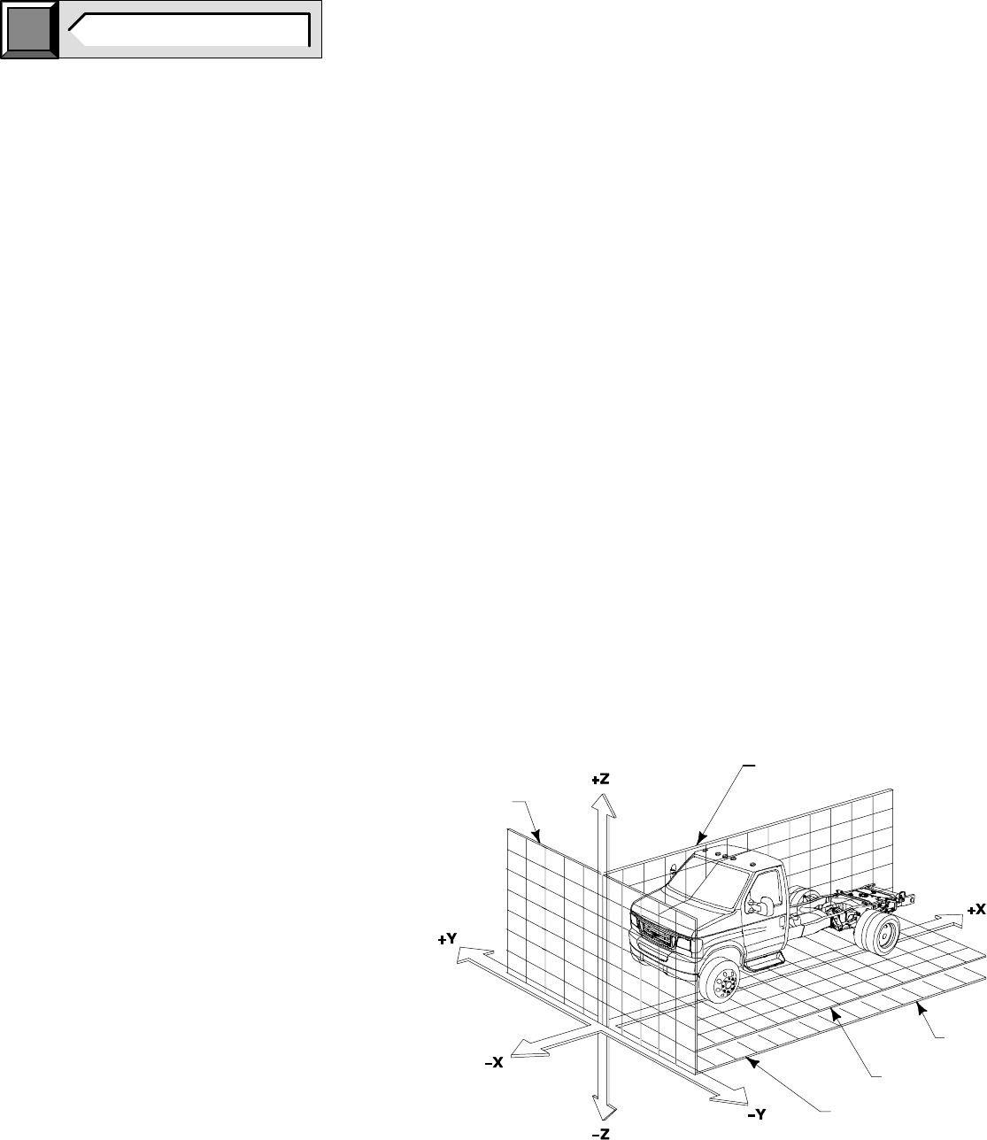
METRIC/U.S. CUSTOMARY UNIT EQUIVALENTS
BB0689
TYPICAL LONGITUDINAL
PLANE
GROUND
HORIZONTAL
PLANE (mm)
PLANE
VERTICAL
TRANSVERSE
PLANE
MM THREE–DIMENSIONAL REFERENCE SYSTEM
X
Y
Z
Z “0 ”
click
here TO RETURN TO INDEX
Page 2 E-550 SUPER DUTY CUTAWAY
Multiply: by: to get: Multiply: by: to get: Multiply: by: to get: Multiply: by: to get:
LINEAR FUEL ECONOMY
inches X 25.4 = millimetres(mm) X 0.03937 = inches miles/gal X 0.4251 = kilometres/litre (km/l) X 2.352 = miles/gal
inches X 2.54 = centimetres (cm) X 0.3937 = inches gal/mile X 2.3524 = litres/kilometre (l/km) X 0.42517 = gal/mile
feet X 0.3048 = metres (m) X 3.281 = feet gal/mile X 235.24 = litres/100 kilometre (l/km) X 0.004252 = gal/mile
AREA POWER
inches2X 645.16 = millimetres2 (mm2) X 0.00155 = inches2horsepower X 0.746 = kilowatts (kW) X 1.34 = horsepower
inches2X 6.452 = centimetres2 (cm2) X 0.155 = inches2ft-lb/min X 0.0226 = watts(W) X 44.27 = ft-lbf/min
feet2X 0.0929 = metres2 (m2) X 10.764 = feet2
TORQUE
VOLUME lb-in X 0.11298 = newton-metres (N-m) X 8.851 = lb-in
inches3X 16387.0 = millimetres3 (mm3) X 0.000061 = inches3lb-feet X 1.3558 = newton-metres (N-m) X 0.7376 = lb-feet
inches3X 16.387 = centimetres3 (cm3) X 0.06102 = inches3
inches3X 0.01639 = litres (1) X 61.024 = inches3VELOCITY
quarts X 0.94635 = litres (1) X 1.0567 = quarts miles/hr X 1.6093 = kilometres/hr (km/hr) X 0.6214 = miles/hr
gallons X 3.7854 = litres (1) X 0.2642 = gallons kilometres/hr X 0.27778 = metres/sec (m/s) X 3.600 = kilometres/hr
feet3X 28.317 = litres (1) X 0.03531 = feet3miles/hr X 0.4470 = metres/sec (m/s) X 2.237 = miles/hr
feet3X 0.02832 = metres3 (m3) X 35.315 = feet3
fluid oz. X 29.57 = millilitres (ml) X 0.03382 = fluid oz. COMMON METRIC PREFIXES
mega (M) = 1,000,000 centi (c) = 0.01
MASS kilo (k) = 1,000 milli (m) = 0.001
ounces (av) X 28.35 = grams (g) X 0.03527 = ounces (av) hecto (h) = 100 micro (µ) = 0.000001
lb (av) X 0.4536 = kilograms (kg) X 2.2046 = lb (av)
tons (2000 lb) X 907.18 = kilograms (kg) X 0.001102 = tons (2000 lb)
tons (2000 lb) X 0.9078 = tonne (t) X 1.1025 = tons (2000 lb)
“ ”

NOTE [ ] DIMENSIONS ARE INCHES.
E-550 SUPER DUTY CUTAWAY
MODEL LINEUP
click
here TO RETURN TO INDEX
Page 3 E-550 SUPER DUTY CUTAWAY
BASE CURB WEIGHT
*
MODEL
SERIES
WHEELBASE
GVWR
STANDARD
ENGINES
BASE
CURB
WEIGHT*
MODEL
SERIES
CODE
WHEELBASE
mm/inches
GVWR
pounds
STANDARD
TRANSMISSION
ENGINES
liters FRONT
pounds REAR
pounds TOTAL
pounds
4051.3
17 500/19 000
4R100
6.8 3405 2785 6190
4051.3
[159.5]
17
,
500/19
,
000
4R100
7.3 3787 2857 6644
4508.5
17 500/19 000
4R100
6.8 3475 2844 6319
4508.5
[177.5]
17
,
500/19
,
000
4R100
7.3 3857 2910 6767
E-550
Su
p
er Duty
E55
4864.1
17 500/19 000
4R100
6.8 3537 2894 6431
S
uper
D
u
t
y
Cutaway
E55
4864.1
[191.5]
17
,
500/19
,
000
4R100
7.3 3921 2958 6879
y
5321.3
17 500/19 000
4R100
6.8 3617 2959 6576
5321.3
[209.5]
17
,
500/19
,
000
4R100
7.3 4003 3019 7022
5930.9
17 500/19 000
4R100
6.8 3722 3046 6768
5930.9
[233.5]
17
,
500/19
,
000
4R100
7.3 4112 3102 7214
* Weight calculated with fuel and fluids to full capacity.
THIS INFORMATION IS PROVIDED TO ASSIST IN THE
INSTALLATION OF SEATS OTHER THAN FORD INSTALLED
SEATS AND TO HELP PRESERVE THE INTENDED
PERFORMANCE OF THE SAFETY AND ERGONOMIC
FEATURES OF THE 2002 E-SERIES. THE MID-TRACK
H-POINT LOCATION MUST BE MAINTAINED IN ORDER TO
COMPLY WITH FMVSS 208 AIRBAG REQUIREMENTS.
NOTES [ ] DIMENSIONS ARE INCHES.
nnn
N
NOTES —
E-550 SUPER DUTY CUTAWAY
SEAT TRACK TRAVEL/H-POINT LOCATION
click
here TO RETURN TO INDEX
Page 4 E-550 SUPER DUTY CUTAWAY
FOREMOST
H POINT
REARMOST
H POINT
MID–TRACK
H POINT
FRONT FIDUCIAL
MARK
SgRP
FOREMOST
H POINT
REARMOST
H POINT
MID–TRACK
H POINT
FRONT FIDUCIAL
MARK
SgRP
DRIVER
MANUAL TRACK
FRONT PASSENGER
MANUAL TRACK
FOREMOST
H POINT
REARMOST
H POINT
MID–TRACK
H POINT
SgRP
FRONT PASSENGER MANUAL TRACK
FIXED SEAT BACK
FRONT FIDUCIAL
MARK
FRONT FIDUCIAL
MARK
SgRP
MID–TRACK
H POINT
DRIVER
POWER TRACK
BB0056
175
[6.9] 155
[6.1] 150
[5.9] 28
[1.1]
84
[3.3]
51
[2.0] 41
[1.6]
13
[0.5] 10
[0.4]
25
[0.1]
33
[1.3]
10
[0.4]
18
[0.7]
208
[8.2]
388 REF
[15.3]
657 REF
[25.9]
24
[0.9]
89
[3.5]10
[0.4] 1.4
[0.05]
168
[6.6] 178
[7.0]
388 REF
[15.3]
657 REF
[25.9]
24
[0.9]
89
[3.5]
10
[0.4] 1.4
[0.05]
168
[6.6] 178
[7.0]
447 REF
[17.6]
650 REF
[25.6]
18
[0.7]
59
[2.3]
10
[0.4] 1.4
[0.05]
129
[5.1] 139
[5.5]
653 REF
[25.8]
427 REF
[16.8]

E-550 SUPER DUTY CUTAWAY
OCCUPANT PROTECTION SYSTEMS
SEAT RESTRAINT SYSTEM
click
here TO RETURN TO INDEX
Page 5 E-550 SUPER DUTY CUTAWAY
INFORMATION
The following recommendations are intended to
assist in the design of seats and seat belt systems
capable of meeting the requirements of the F/CMVSS
207, 208, 209 and 210 except for front seating
positions for vehicles having a GVWR of 3855 kg
[8500 lb] or less, and an Unloaded Vehicle Weight of
2495 kg [5500 lb] or less.These recommendations
are based on testing and analyses performed by Ford
Motor Company.
Ford cautions subsequent stage manufacturers to
note the definition of “Designated Seating Positions”
on page 26 of the “2001 Body Builder Book”. If a
position can reasonably be used by a 5th percentile
adult female for seating and the overall seat
configuration and vehicle design make it likely that the
position will be used by an occupant while the vehicle
is in motion, then the position must be considered to
be a “Designated Seating Position” for determination
of compliance to U.S. and Canadian motor vehicle
safety standards.
Seat and seat belt systems may take many forms; this
list of recommendations cannot cover all possibilities.
Strict adherence to these suggestions will not ensure
that systems will comply with F/CMVSS 207, 208, 209
and 210. Responsibility for determining compliance to
appropriate F/CMVSS regulations is that of the final
stage manufacturer. Accordingly, Ford Motor
Company makes no representation as to the
appropriateness of any particular recommendation in
its specific application of a particular design or act of
intermediate or final stage manufacture.
To confidently verify compliance with F/CMVSS 207,
208, 209 and 210, the testing of representative
systems to applicable F/CMVSS 207, 208, 209 and
210 procedures is recommended. Questions
regarding compliance with F/CMVSS regulations
should be directed to your legal counsel, the National
Highway Traffic Safety Administration, or Transport
Canada.
SEAT SYSTEMS
1. For Incomplete E-Series Vans and Cutaways with
a GVWR over 3855 kg (8500 lb) purchased with
the front seat delete option, Ford strongly
recommends following the practices specified in
the compliance representations for F/CMVSS 208
that apply to Incomplete E-Series Vans with a
GVWR of 3855 kg (8500 lb) or less and
completed units Unloaded Vehicle Weight of 2495
kg (5500 lb) or less that are purchased without
front seats.
2 Any additional seats and seat anchorages
installed by subsequent stage manufacturers
must meet F/CMVSS 207 requirements and
specifications.
3. Do not modify or alter Ford furnished seating or
occupant restraint system. When utilizing the
Ford seat delete package, care must be taken to
insure proper function of the seat adjustment
latching mechanism, electrical wiring and seat
belt buckle pretensioner. Refer to Bulletin Q-48 for
wire routing.
4. If the seat or seat belt components are temporarily
removed for any reason, they must be reinstalled
in accordance with the instructions and
specifications found on the following pages for
E-Series or the applicable
Ford Truck Shop
Manual.
5. Seating systems that include the attachment of
lap belt or shoulder belt assemblies should also
consider the requirements of F/CMVSS 210 as
part of the seating system.
6. Seating system components should be free of
sharp edges to prevent damage to seat belt
systems when the belts could potentially contact
the seating system components.
7. Seats should be mounted with appropriate
fasteners in the mounting holes provided, since
these holes are located to utilize floor pan
structural reinforcements. (See figures on
following pages.)
8. If additional holes are required for any reason,
their locations should be carefully selected so that
the structural integrity of the floor pan will not be
compromised and to prevent damage to other
components located below the floor.
9. Seating systems should be designed to be
compatible with the seat belt systems, so as to
permit proper adjustment, allow for occupant
movement and provide convenient accessibility of
the restraint system buckle release.
10. Seats not designated for occupancy while the
vehicle is in motion must be conspicuously
labeled as such.
LAP AND SHOULDER BELT SYSTEMS
1. The front seats are equipped with a pyrotechnic
buckle pretensioner. The buckle pretensioner
reduces slack in the lap and shoulder safety belt
by pulling the buckle downward. The buckle
pretensioners and air bags operate on the same
sensors and will function simultaneously.
2. Additional lap and shoulder belt assemblies,
including retractors and hardware, must comply
with the requirements of F/CMVSS 208 and 209.
3. Additional lap and shoulder belt system
anchorages must comply with the requirements of
F/CMVSS 210.
4. Lap and shoulder belt systems that are attached
to seat frame or base may affect compliance of
the seating system with the requirements of
F/CMVSS 207.
5. Ford lap and shoulder belts, retractors and
attaching hardware should not be altered or
modified in any way. The reinstallation of these
components should follow the instructions and
specifications on the following pages, or those in
the appropriate
Ford Truck Shop Manual
.
6. Lap and shoulder belt assemblies should be
compatible with the seat systems and
anchorages so that lap belts will be properly
positioned about the occupant’s pelvis to provide
proper adjustment and fit. The buckle and buckle
release are properly located with respect to the
occupant and must comply with the requirements
of F/CMVSS 208.
7. Seat belt warning system activation/deactivation,
where applicable, should be provided by the lap
and shoulder belt assembly.
WARNING:
THE SEAT BELT BUCKLE PRETENSIONER,
AIRBAGS AND ELECTRONIC SENSOR MODULE
ARE BAR CODED WITH A UNIQUE SERIAL
NUMBER WHICH IS MATCHED TO THE VEHICLE
VIN. TO MAINTAIN THE OCCUPANT PROTECTION
SYSTEM PERFORMANCE, THE COMPLETED
VEHICLE MUST CONTAIN THE SAME SEAT BELT
BUCKLE PRETENSIONER, AIR BAGS AND
ELECTRONIC SENSOR MODULE THAT WERE
INSTALLED BY FORD MOTOR COMPANY.
FAILURE TO DO SO COULD RESULT IN SERIOUS
INJURY IN THE EVENT OF A COLLISION.
OCCUPANT PROTECTION ZONE AND OVERHEAD
CONSOLE
For vehicles completed with an Unloaded Vehicle
Weight (UVW) greater than 2495 kg [5500 lb], Ford
strongly recommends following the practices in the
compliance representations for F/CMVSS 208 regarding
overhead console specifications that apply to
Incomplete E-Series Vans with a GVWR of 3856 kg
[8500 lb] or less and completed units have an Unloaded
Vehicle Weight of 2495 kg [5500 lb] or less. (Refer to
the
Incomplete Vehicle Manual
for these compliance
representations.)
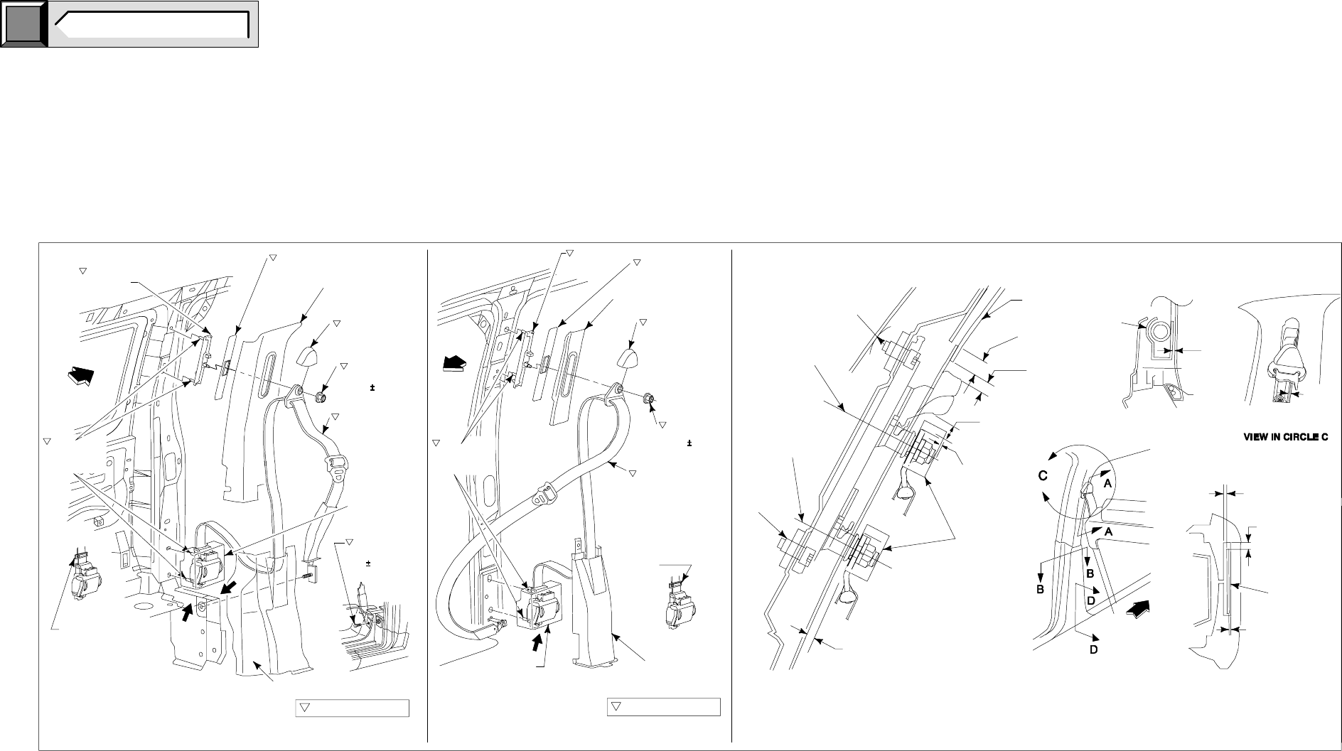
FRONT SEATS RESTRAINT INSTALLATION
RH PASSENGER
SEAT RESTRAINT SYSTEM INSTALLATION
LH DRIVER SEAT
RESTRAINT SYSTEM INSTALLATION
NOTE - [ ] DIMENSIONS ARE FT-LB OR INCHES.
E-550 SUPER DUTY CUTAWAY
OCCUPANT PROTECTION SYSTEMS
SEAT RESTRAINT SYSTEM
click
here TO RETURN TO INDEX
Page 6 E-550 SUPER DUTY CUTAWAY
6.0 MIN. CLEARANCE
TO ALL ADJUSTED
POSITIONS
6.0 MIN.
SEAT BELT
WEBBING
6.0 MIN. CLEARANCE
AROUND BELT
PERIPHERY AT MAX.
TRAVEL POSITIONS
6.0 MIN.
UP POSITION
6.0
3.0
RETRACTOR
9.5 RADIUS MIN.
13.0 MIN. FROM
COVER TO
RELEASE KNOB
2.0 MIN.
(WITH D–RING
LOCATED ON
SHLDR.BOLT)
1560262 REF.
(3) FULL
THREAD
EXPOSED
DOWN
ADJUSTED
POSITION
UP
ADJUSTED
POSITION
6.5 MIN. FROM
RELEASE KNOB
TO INTERIOR TRIM
12.5 MIN.
OVERLAP
SECTION A–A SECTION B–B
MAIN VIEW
SECTION D–D
FRONT OF
VEHICLE
INTERIOR TRIM
CRITICAL CONTROL ITEM
VIEW A
A
VIEW B
B
AVIEW A
CRITICAL CONTROL ITEM
FRONT OF
VEHICLE
FRONT OF
VEHICLE
XC2A–15602B82
ADJ. ASY. PANEL ASY.
UPPER
F65B–15602B90
COVER ASY.
F7UB–1560262
COVER ASY.
1 REQ’D. EA. SIDE
N806773–S190
NUT – TORQUE
40.0 6.0 Nm
15611B09
BELT AND
RETRACTOR ASY.
ALL CUTAWAY
MODELS ONLY
368273–S100
BOLT TORQUE
40 6 Nm
PANEL ASY. COVER
ALL WAGON – VAN MODELS ONLY
DRIVER – SEAT
(LEFT HAND) INSTALLATION
SHIPPING CLIP MUST
REMAIN CLIPPED TO
BELT PRIOR TO
ATTACHMENT TO
RETRACTOR INTO
VEHICLE.
CUTAWAY & VAN MODELS
ADJ. ASY. F65B–602B90
COVER ASY.
F7UB–1560262
COVER ASY.
1 REQ’D. EA. SIDE
N806773–S190
NUT – TORQUE
40.0 6.0 Nm
611B08
BELT AND
RETRACTOR ASY.
SHIPPING CLIP MUST
REMAIN CLIPPED TO
BELT PRIOR TO
ATTACHMENT TO
RETRACTOR INTO
VEHICLE.
PANEL ASY.
COVER
ALL WAGON – VAN MODELS ONLY
PASSENGER SEAT
(RIGHT HAND) INSTALLATION
ALL CUTAWAY
MODELS ONLY
BB0464
+
PIA
BOLT–TORQUE
40.0 6.0 Nm
[29.5 4 ft–lb]
+
–
+
–
PIA
BOLT–TORQUE
40.0 6.0 Nm
[29.5 4 ft–lb]
+
–
+
–
XC2A–15602B82
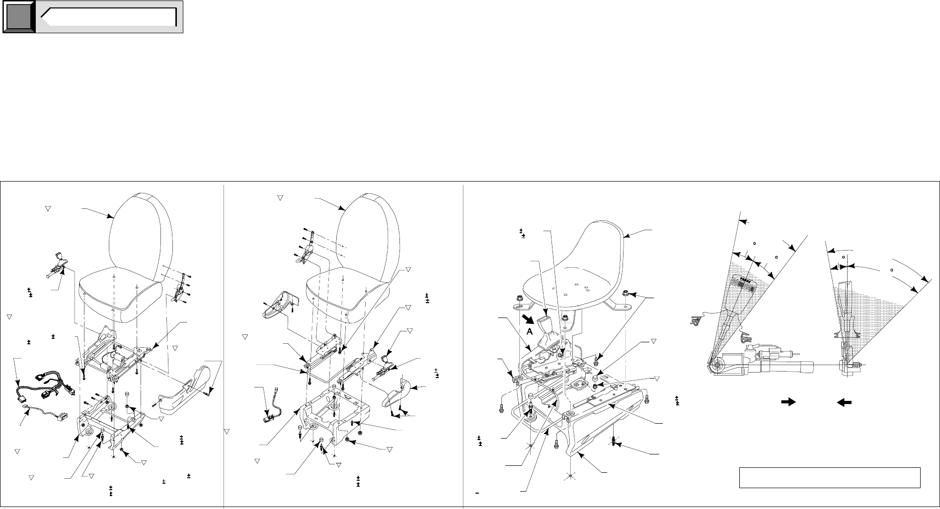
LH DRIVER
SEAT INSTALLATION RH PASSENGER
SEAT INSTALLATION LH DRIVER
SEAT DELETE OPTION
POWER LH SHOWN
SEAT ASY.
N802351–S424
STUD 2 REQ’D.
M200751
TRACK ASY.
FRT. ST.
56912–S58
SCREW 4.2 x 19
TAPPING
N800937–S424
NUT & WASHER ASY.
2 REQ’D.
55.0 8.3 Nm
N620481–S58
NUT M8 x 1.75 HEX FLANGE
TORQUE 25.0 3.8 Nm
N811326–S424
SCREW 2 REQ’D.
55.0 8.3 Nm
611D02–A
STUD COVER
4 REQ’D.
M2003089
SUPPORT ASY.
SWITCH ASY.
ST. CONTROL
F7UB–14A699–A
WIRE ASY.–
ST. CONTROL
N801078–S424
SCREW M8 x 1.25 HEX
4 REQ’D.
TORQUE 25.0 3.8 Nm
PIA BOLT
TORQUE
40.0 6.0 Nm
POWER RH SHOWN
SEAT ASY.
N801078–S424
SCREW M8x1.25
HEX 4 REQ’D.
TORQUE
25.0 3.8 Nm
A2008167
TRACK ASY.
F7UB–1561202–A
PYROTECHNIC
ASY. R.H.
PIA BOLT
TORQUE
40.0 6.0 Nm
COVER–FRT.
ST. PIVOT
36912–S58
SCREW 4.2 x 19.0
TAPPING
N811326–S424
SCREW 2 REQ’D.
55.0 8.3 Nm
N620482–S424
M10 HEX NUT HD.
NUT W/WASHER
4 REQ’D.
N802351–S424
STUD 2 REQ’D.
611D02–A
STUD COVER
4 REQ’D.
F7UB–1562506–A
SUPPORT ASY.
(R.H. MNL)
F7US–14A699–DB
WIRE ASY.
F7UB–1561755–A
HANDLE FRT. ST.
TRACK
A2008168
TRACK ASY.
CLEARANCE
ZONE
CLEARANCE
ZONE
10
45
10
15
SIDE VIEW REAR VIEW
CENTER OF VEHICLE
FRONT OF VEHICLE
PRETENSIONER CLEARANCE ZONE
T2007563
SEAT
F7UB–1561202–A
BUCKLE ASY.
A2008170 DRIVER
A2008168 PASS.
R.H. TRACK
NUTS & BOLTS 4 REQ’D.
FOR SHIPPING
PURPOSES
ONLY
611D02–A
STUD COVER
4 REQ’D.
N800937–S424
NUT & WASHER ASY.
2 REQ’D.
55.0 8.3 Nm
A2008169 DRIVER
A2008167 PASS.
R.H. TRACK
N802351–S424
STUD 2 REQ’D.
F7UB–1567506–A
SUPPORT ASY.
COVER FRT
ST. PVT.
PIA BOLT
TORQUE
40.0 6.0 Nm
N811326–S424
SCREW 2 REQ’D.
55.0 8.3 Nm
F7US–14A699–DB
WIRE ASY.
F7UB–1561755–A
HDL.FRT.ST.TRK.
THE SHADED AREA MUST BE FREE OF OBSTRUCTIONS.
THE BUCKLE MOVES DOWNWARD THROUGH THE SHADED
ZONE AND MUST NOT CONTACT ANY COMPONENT WHICH
MAY DEGRADE ITS PERFORMANCE.
IMPORTANT:
DO NOT INSTALL ADDITIONAL COMPONENTS IN THE SHADED
AREA, OR ALTER OR MODIFY THIS AREA.
VIEW A
BB0475
[18.4 2.8 FT-LB]
[40.6 6 FT-LB]
[29.5 4 FT-LB]
[40.6 6 FT-LB]
[40.6 6 FT-LB]
[40.6 6 FT-LB]
[40.6 6 FT-LB]
[29.5 4 FT-LB]
[29.5 4 FT-LB]
[18.4 2.8 FT-LB]
[18.4 2.8 FT-LB]
NOTE - DIMENSIONS ARE FT-LB OR INCHES.
E-550 SUPER DUTY CUTAWAY
OCCUPANT PROTECTION SYSTEMS
SEAT RESTRAINT SYSTEM
click
here TO RETURN TO INDEX
Page 7 E-550 SUPER DUTY CUTAWAY
E-550 SUPER DUTY CUTAWAY
OCCUPANT PROTECTION SYSTEMS
AIRBAG SUPPLEMENTAL RESTRAINT SYSTEM
BB0538
AIR BAG
SAMPLEXXXXXXXXXXX
click
here TO RETURN TO INDEX
Page 8 E-550 SUPER DUTY CUTAWAY
INFORMATION
Ford urges careful consideration of the
recommendations that follow. They are based on
analyses of component and vehicle tests, actual
service situations, and engineering judgments.
Disregard of these recommendations may affect the
durability, reliability, handling and performance
characteristics of a completed vehicle and may result
in elevated underbody temperatures, increase the
potential for fire, or may affect the safety of the
occupants in the event of an accident.
These recommendations are supplemental to U.S.
and Canadian Motor Vehicle Safety compliance
representations provided in the
Incomplete Vehicle
Manua
l (IVM). Also, additional information is provided
in the
Ford Truck Service Manual
which may be
helpful to subsequent stage manufacturers.
The completed vehicle in the “Loaded” condition must
not exceed the front GAWR, rear GAWR, or the GVWR.
(“Loaded” means the completed vehicle weight with the
maximum fluid capacity necessary for vehicle operation,
plus 150 lb for each designated seating position, and
an additional allowance for any cargo weight
advertised by the manufacturer). The GAWRs and
GVWR are on the label affixed to the cover of the
Incomplete Vehicle Manual
.
Subsequent Stage Manufacturers are encouraged
to contact the Ford Truck Body Builder Advisory
Service if they have any questions concerning
these recommendations.
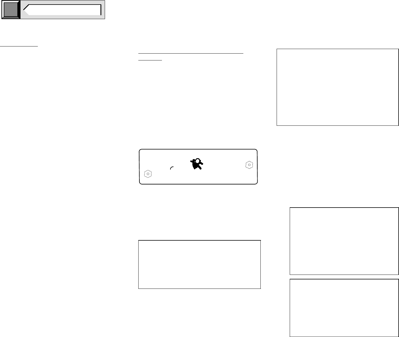
AIRBAG SUPPLEMENTAL RESTRAINT
SYSTEM
Some trucks produced by Ford Motor Company are
equipped with an Airbag Supplemental Restraint
System (SRS). Vehicles equipped with this system
will have the words “AIRBAG” and an air bag symbol
on the VIN plate located on the top driver-side corner
of the instrument panel. System components are
shown in their vehicle locations on the following
pages.
Included on the vehicle identification number -VIN-
plate (visible through the windshield) of the vehicle,
manufactured by Ford with a driver’s air bag, are the
words “AIR” and “BAG” and a pictogram for the airbag
separating the two (see illustration below).
Detailed system and service information will be found
in the
Ford Truck Service Manual
for the appropriate
type and model year. Ford Motor Company urges the
subsequent stage manufacturers to become familiar
with this system prior to modifying vehicles that are so
equipped.
CAUTION:
DO NOT REMOVE THE STEERING COLUMN,
STEERING WHEEL AND AIRBAG MODULE AS AN
ASSEMBLY FROM THE VEHICLE UNLESS (1) THE
COLUMN IS LOCKED TO PREVENT ROTATION, OR
(2) THE LOWER END OF STEERING SHAFT IS
SECURED (e.g., by wire) IN SUCH A WAY THAT THE
STEERING WHEEL CANNOT BE ROTATED.
WARNING:
THE SEAT BELT BUCKLE PRETENSIONER,
AIRBAGS AND ELECTRONIC SENSOR MODULE
ARE BAR CODED WITH A UNIQUE SERIAL
NUMBER WHICH IS MATCHED TO THE VEHICLE
VIN. TO MAINTAIN THE OCCUPANT PROTECTION
SYSTEM PERFORMANCE, THE COMPLETED
VEHICLE MUST CONTAIN THE SAME SEAT BELT
BUCKLE PRETENSIONER, AIR BAGS AND
ELECTRONIC SENSOR MODULE THAT WERE
INSTALLED BY FORD MOTOR COMPANY. FAILURE
TO DO SO COULD RESULT IN SERIOUS INJURY IN
THE EVENT OF A COLLISION.
If electrical work is performed in the steering column
area, the instrument panel or the air bag system, the
system must be deactivated to avoid unwanted
inflation of the air bag. To do this, follow the procedure
described on this page.
DEACTIVATION PROCEDURE
1. Disconnect all negative battery cable(s), and
power supplies (if equipped).
2. Wait 1 minute. This is the time required for
backup power supply in diagnostic monitor to
deplete its stored energy.
WARNING:
TO AVOID ACCIDENTAL DEPLOYMENT AND
POSSIBLE PERSONAL INJURY, THE BACKUP
POWER SUPPLY MUST BE DEPLETED BEFORE
REPAIRING OR REPLACING ANY AIRBAG
SUPPLEMENTAL RESTRAINT SYSTEM (SRS)
COMPONENTS. TO DEPLETE THE BACKUP
POWER SUPPLY ENERGY, DISCONNECT THE
BATTERY GROUND CABLE AND WAIT ONE
MINUTE. BE SURE TO DISCONNECT
AUXILIARY BATTERIES AND POWER
SUPPLIES (IF EQUIPPED).
WARNING:
CARRY A LIVE AIRBAG MODULE WITH THE
AIRBAG AND TRIM COVER POINTED AWAY
FROM YOUR BODY. THIS WILL REDUCE THE
RISK OF INJURY IN THE EVENT OF AN
ACCIDENTAL DEPLOYMENT.
WARNING:
DO NOT SET A LIVE AIRBAG MODULE DOWN
WITH THE TRIM COVER FACE DOWN.
3. Remove fasteners retaining driver airbag
module to steering wheel. Disconnect driver
airbag connector and remove the bag from
steering wheel. Place the bag on a flat surface
with trim cover facing upward. Connect an
Airbag Simulator (Part # 105-R0012 in the
Rotunda Tool catalog) to the air bag connector
on the wire harness in the steering wheel.
4. Disconnect passenger airbag module connector
and replace it with an Airbag Simulator (Part #
105-R0012 in the Rotunda Tool catalog) to the
airbag connector on the wire harness in the I/P.
5. Reconnect all negative battery cables and
power supplies (if equipped).
REACTIVATION PROCEDURE
1. Disconnect all negative battery cable(s) and
power supplies (if equipped).
2. Wait 1 minute for backup power supply to
deplete stored energy.
3. Remove Airbag Simulator and reconnect driver
airbag connector. Position driver airbag on
steering wheel and secure with fasteners
(10mm). Tighten fasteners to 2.7-3.7 Nm.[24-32
in-lb].
4. Remove Airbag Simulator and reconnect
passenger airbag connector.
5. Reconnect all negative battery cables and
power supplies (if equipped).
6. PROVE-OUT the system.
PROVE-OUT SYSTEM PROCEDURE
Prove-out system means to turn the ignition switch
from OFF to RUN and visually monitor the airbag
indicator. The airbag will light continuously for
approximately six seconds and then turn off. If an
airbag system fault is present, the indicator will
either fail to light, remain lit continuously or light in a
flashing manner. The flashing manner may not
occur until approximately 30 seconds after the
ignition switch has been turned from OFF to RUN.
This is the time required for the diagnostic monitor
to complete the testing of the airbag system. If the
airbag indicator is inoperative and an airbag
system fault exists, a tone will sound in a pattern of
five sets of five beeps. If this occurs, the airbag
indicator will need to be serviced before further
diagnosis can be done.
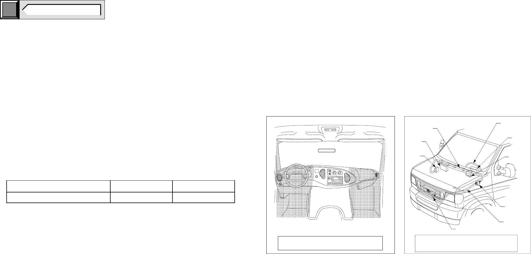
BB0466
DO NOT INSTALL ADDITIONAL COMPONENTS IN THE
SHADED AREAS, OR ALTER OR MODIFY THESE AREAS.
ELECTRONIC
CRASH SENSOR
MODULE
AIRBAG
INSTRUMENT
PANEL HARNESS
STEERING
WHEEL
AIRBAG
READINESS
INDICATOR
CONNECTOR
AT SAFETY
WALL
ENGINE
COMPARTMENT
HARNESS
CRASH
SENSOR
DO NOT MODIFY OR ALTER ANY COMPONENTS OR AREAS
OF THE VEHICLE IN THE VICINITY OF THE COMPONENTS
THAT ARE IDENTIFIED IN THIS ILLUSTRATION.
AIRBAG USAGE CHART
E-550 SUPER DUTY CUTAWAY
OCCUPANT PROTECTION SYSTEMS
AIRBAG SUPPLEMENTAL RESTRAINT SYSTEM
click
here TO RETURN TO INDEX
Page 9 E-550 SUPER DUTY CUTAWAY
VEHICLE DRIVER PASSENGER
E-550 Super Duty Cutaway Standard Front Standard Front
NOTES [ ] DIMENSIONS ARE INCHES.
NOTES A, B, F, R DIMENSIONS, SEE PAGE 11.
NOTES 25 MM CLEARANCE IS REQUIRED BETWEEN ALL FUEL TANK COMPONENTS AND
NOTES SECOND UNIT BODY. CONTACT BODY BUILDERS ADVISORY SERVICE FOR NOTES
NOT ESINFORMATION.
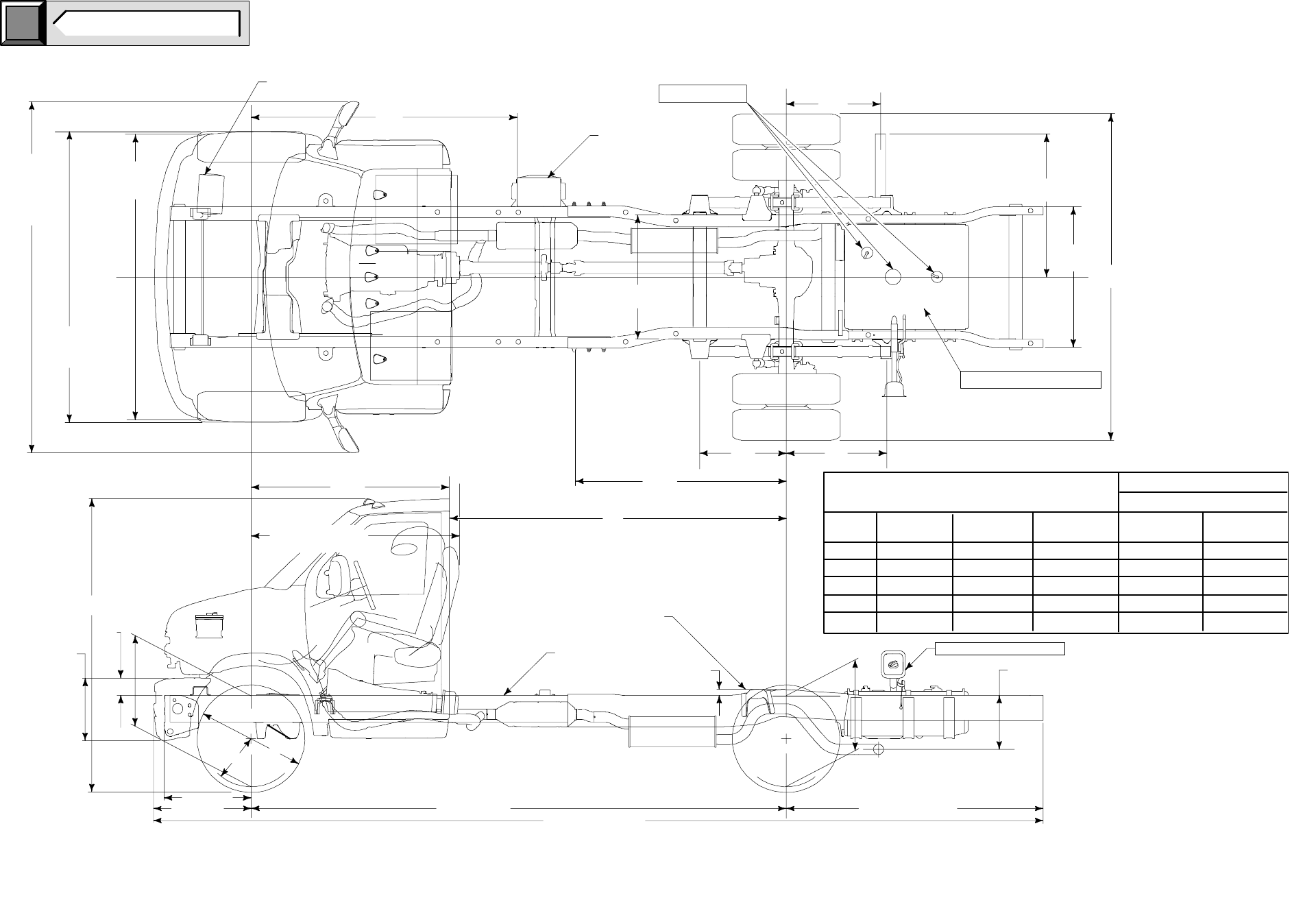
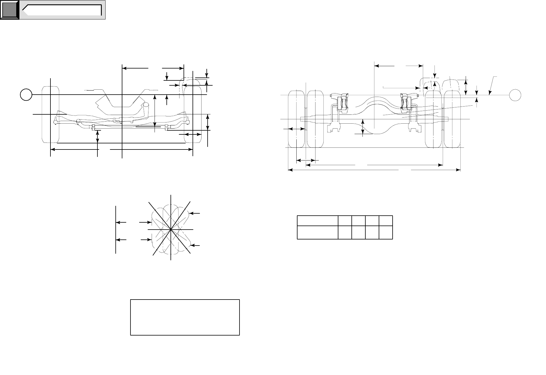
DIMENSIONS
WB OVERHANG OVERALL
LENGTH CURB LOADED
[159.5]
[177.5]
[191.5]
[209.5]
[233.5]
1948.8 [76.7]
2133 [84.0]
2438 [96.0]
2895 [114.0]
6736 [265.2]
7193 [283.2]
7734 [304.5]
8496 [334.5]
9563 [376.5]
2270 [89.3]
OVERALL HEIGHT
CH
1948.8 [76.7] 2270 [89.3]
2270 [89.3]
2270 [89.3]
2270 [89.3] 2201 [86.6]
2201 [86.6]
2201 [86.6]
2201 [86.6]
2201 [86.6]
AF REAR
CA
2540 [100.0]
3353 [132.0]
3810 [150.0]
4420 [174.0]
2997 [118.0]
FLARES
1st BATTERY
LOCATION
2nd BATTERY
LOCATION
1575 DRIVER SEAT
(REARMOST)
625 WHEELBASE
NORMAL TOP
OF FRAME
TOP OF FRAME KICKUP
AT OF REAR AXLEC
L
FRONT AXLE REAR AXLE
C
LC
L
OVERALL LENGTH REAR OVERHANG
FUEL FILLER LOCATION
EXHAUST OUTLET
55 GAL STD FUEL TANK
BB0688
MIRRORS
CH
VEHICLE
C
L
F
AB
R
1658.9
[65.3]
657
[25.9] 740
[29.1]
2456
[96.7]
1067
[42.0]
1083
[42.6]
716
[28.2]
2016
[79.3]
2605
[102.5]
2203
[86.7]
EXTENDED
2754
[108.4] BUMPER
2186
[86.0]
1510
[59.4]
CA
[62.0]
475
[18.7]
132
[5.2]
[25.0]
736 [29.0] AF
44
[1.8] 411
[16.2]
955
[37.6]
SEE NOTES
DIMENSIONAL DATA
E-550 SUPER DUTY CUTAWAY
159.5 - 233.5 WHEELBASE (DRW)
click
here TO RETURN TO INDEX
Page 10 E-550 SUPER DUTY CUTAWAY
DEPARTURE ANGLE
AT GVWR
APPROACH ANGLE
AT GVWR
GROUND
LINE
899 [35.4]
1198 [47.2]
MINIMUM GROUND CLEARANCE LINE
AT GVWR (LOADED) – COMPONENTS
THAT COULD DISABLE A VEHICLE
SHOULD BE 30.0 [1.18] ABOVE THE
MINIMUM CLEARANCE LINE.
BB0684
GJ
“B” TIRE DIAMETER
“A” STATIC LOADED RADIUS
162
[6.4]
899
[35.4]
1198
[47.2]
182
[7.2] 162
[6.4]
E-550 SUPER DUTY CUTAWAY
VEHICLE HEIGHT DATA
TIRE/GROUND CLEARANCE DATA
NOTE [ ] DIMENSIONS ARE INCHES.
click
here TO RETURN TO INDEX
Page 11 E-550 SUPER DUTY CUTAWAY
F F R R CH
HEIGHT @
FRONT AXLE(1) HEIGHT @
FRONT AXLE(1) HEIGHT @
REAR AXLE(1) HEIGHT @
REAR AXLE(1)
OVERALL HEIGHT
OF VEHICLE
(STANDARD SPRINGS)(1)
GVWR
pounds
standard/
FRONT GAWR
MIN/MAX
COMBINED
FRONT SPRING
CAPACITY RATE
@ GROUND
pounds
BASE CURB
WEIGHT
mm [in] LOADED
mm [in]
REAR GAWR
MIN/MAX
pounds
standard/
optional
COMBINED
REAR SPRING
CAPACITY RATE
@ GROUND
pounds
BASE CURB
WEIGHT
mm [in] LOADED
mm [in] UNLOADED
mm [in] LOADED
mm [in]
MODEL WB standard/
optional MINIMUM TIRE MIN/MAX
pounds STD SPRING STD SPRING STD SPRING STD SPRING STD SPRING STD SPRING
E-550
SUPER DUTY
CUTAWAY ALL 17,500
19,000 225/70R19.5F 6000 6000 772 [30.3] 703 [27.6] 11,500/13,500 11,500/13,500 817.8
[32.2] 725.0
[28.5] 2270
[89.3] 2201
[86.6]
(1) — The Height Data shown represents dimensions of a nominal vehicle with no options. Actual height may vary due to production tolerances.
BASE VEHICLE UNLOADED CURB WEIGHT
ALL SEASON TIRE DATA TREAD WIDTH OW TH TW GROUND CLEARANCE
A
B
C
FW
RW
OVERALL
STD
STD
G J
MODEL TIRE SIZE
A
B
C
FW RW
OVERALL
WIDTH
STD
STD
APPROACH ANGLE DEPARTURE ANGLE
STATIC
LOADED
RADIUS
MAX.
DIAMETER
MAX.
SECTION
WIDTH
RIM
WIDTH FRONT REAR REAR SPRING SPRING 159.5
WB 177.5
WB 191.5
WB 209.5
WB 233.5
WB 159.5
WB 177.5
WB 191.5
WB 209.5
WB 233.5
WB
E-550 225/70R19.5F 378
[14.9] 811
[31.9] 226
[8.9] 152
[6.0] 1999
[78.7] 1970
[77.5] 2456
[96.7] 205.7
[8.1] 708
[27.9] 33°33°33°33°33°15.9°15.9°14.5°12.6°10.6°
E-550 SUPER DUTY CUTAWAY
ALL WHEELBASES
NOTES [ ] DIMENSIONS ARE INCHES.
NOTES C, FW, TW, TH DIMENSIONS, SEE PAGE 11.
TH
TW
25.1
FW
TW
TH
1
1
C
FRONT VIEW
C
L
VEHICLE
[1.0] CLEARANCE
C
25.1
REAR VIEW
MAX. RIGHT TURN
MAX. LEFT TURN
LEFT FRONT TIRE
TW L
TW R
VEHICLE
PLAN VIEW
C
L
= DISTANCE FROM
= DISTANCE FROM TOP OF FRAME
C
LOF VEHICLE TO
SIDE OF TIRE IN MODIFIED JOUNCE.
SPACERS TO TOP OF TIRE IN
MODIFIED JOUNCE.
TW
TH
BB0685
C
L
VEHICLE
215
25.4 MIN.
0.5 MIN.
[1.1]
CLEARANCE
NORMAL
TOP OF FRAME
[0.5]
225/70R/19.5F 838 213 640 668
TW TH
11
TWLTWR
27.9
[96.7]
2456
[77.5]
1970
[8.4]
271
[10.6]
[33.0] [8.4] [25.2] [26.3]
12.7 MIN. CLEARANCE
[1.0]
25.4 MIN. CLEARANCE
212.3
[8.3]
195
[7.6]
248
[9.8]
click
here TO RETURN TO INDEX
Page 12 E-550 SUPER DUTY CUTAWAY
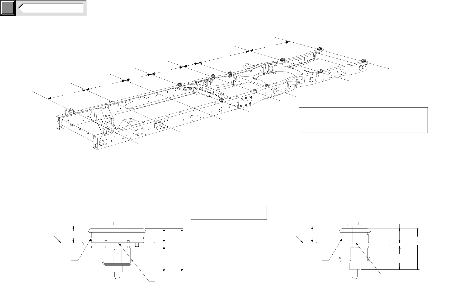
NOTES [ ] DIMENSIONS ARE INCHES.
NOTES C, CH, FW DIMENSIONS, SEE PAGE 11.
E-550 SUPER DUTY CUTAWAY
159.5 WHEELBASE FRAME DATA
BODY PUCKS
BB0679
952
[37.4]
847
[33.3]
613
[24.1]
813
[32.0]
381
[15.0]
1230
[48.4]
1460
[57.5]
47.0 FREE
STATE
35.7 DIA HOLE IN FRAME
[1.4]
[1.8]
BOLTS & BODY
MOUNTS IN
DUNNAGE
PACKAGES
TORQUE TO
70 +/– 10.5 Nm
54.1 [2.1] FREE
(54.1 [2.1] w/LOAD)
41.6 [1.6] FREE
(32.6 [1.2] w/LOAD)
TOP OF FRAME
48.9 FREE
STATE[1.9]
BOLTS & BODY
MOUNTS IN
DUNNAGE
PACKAGES
TORQUE TO
70 +/– 10.5 Nm
TOP OF FRAME
35.7 DIA HOLE IN FRAME
[1.4]
102.7 FREE
[4.0]
107.3 FREE
[4.2]
NOTE: SPACER OPTIONS NOT AVAILABLE ON
E–550. CONTACT BODY BUILDERS ADVISORY
SERVICE FOR INFORMATION REGARDING THE
PURCHASE OF SPACERS.
BODY PUCKS (OPTIONAL)
SHIPPED IN DUNNAGE
43.5 [1.7] FREE
(32.6 [1.2] w/LOAD)
56.8 [2.2] FREE
(54.2 [2.1] w/LOAD)
159.5 WB
click
here TO RETURN TO INDEX
Page 13 E-550 SUPER DUTY CUTAWAY
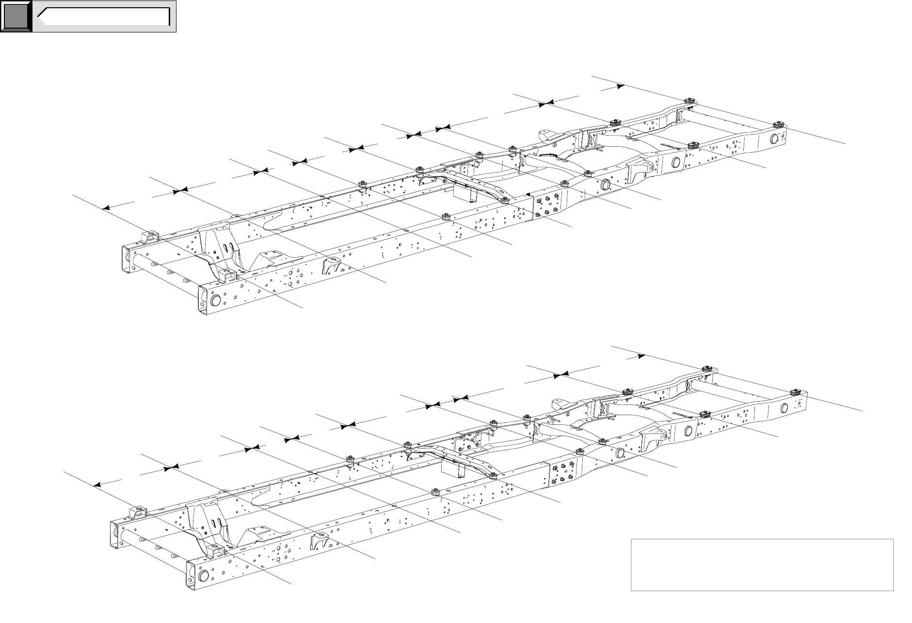
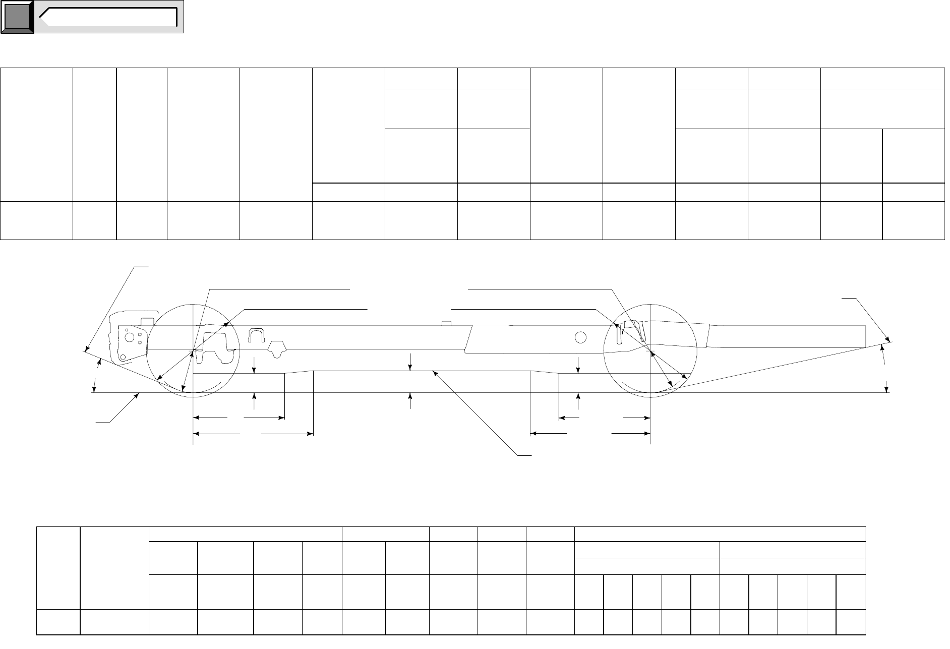
NOTE [ ] DIMENSIONS ARE INCHES.
E-550 SUPER DUTY CUTAWAY
177.5 - 191.5 WHEELBASE
FRAME DATA
952
[37.4]
847
[33.3]
613
[24.1]
527
[20.7]
743
[29.3]
1231
[48.4]
1460
[57.4]
381
[15.0]
BB0681
952
[37.4]
847
[33.3]
462
[18.2]
677
[26.6]
1099
[43.2]
1353
[53.2]
1460
[57.5]
381
[15.0]
BB0680
NOTE: SPACER OPTIONS NOT AVAILABLE ON
E–550. CONTACT BODY BUILDERS ADVISORY
SERVICE FOR INFORMATION REGARDING THE
PURCHASE OF SPACERS.
177.5 WB
191.5 WB
click
here TO RETURN TO INDEX
Page 14 E-550 SUPER DUTY CUTAWAY
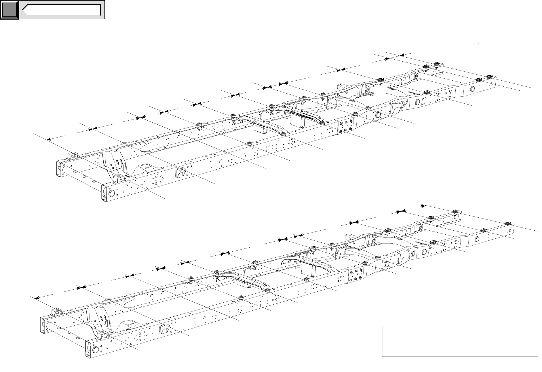
NOTE [ ] DIMENSIONS ARE INCHES.
E-550 SUPER DUTY CUTAWAY
209.5 - 233.5 WHEELBASE
FRAME DATA
952
[37.4]
847
[33.3]
462
[18.2]
677
[26.6]
822
[32.3]
1353
[53.2]
1460
[57.4]381
[15.0]
734
[28.9]
BB0683
305
[12.0]
BB0682
NOTE: SPACER OPTIONS NOT AVAILABLE ON
E–550. CONTACT BODY BUILDERS ADVISORY
SERVICE FOR INFORMATION REGARDING THE
PURCHASE OF SPACERS.
952
[37.4]
847
[33.3]
462
[18.2]
677
[26.6]
822
[32.3]
1353
[53.2]
1460
[57.4]
1344
[52.9]
762
[30.0]
381
[15.0]
209.5 WB
233.5 WB
click
here TO RETURN TO INDEX
Page 15 E-550 SUPER DUTY CUTAWAY
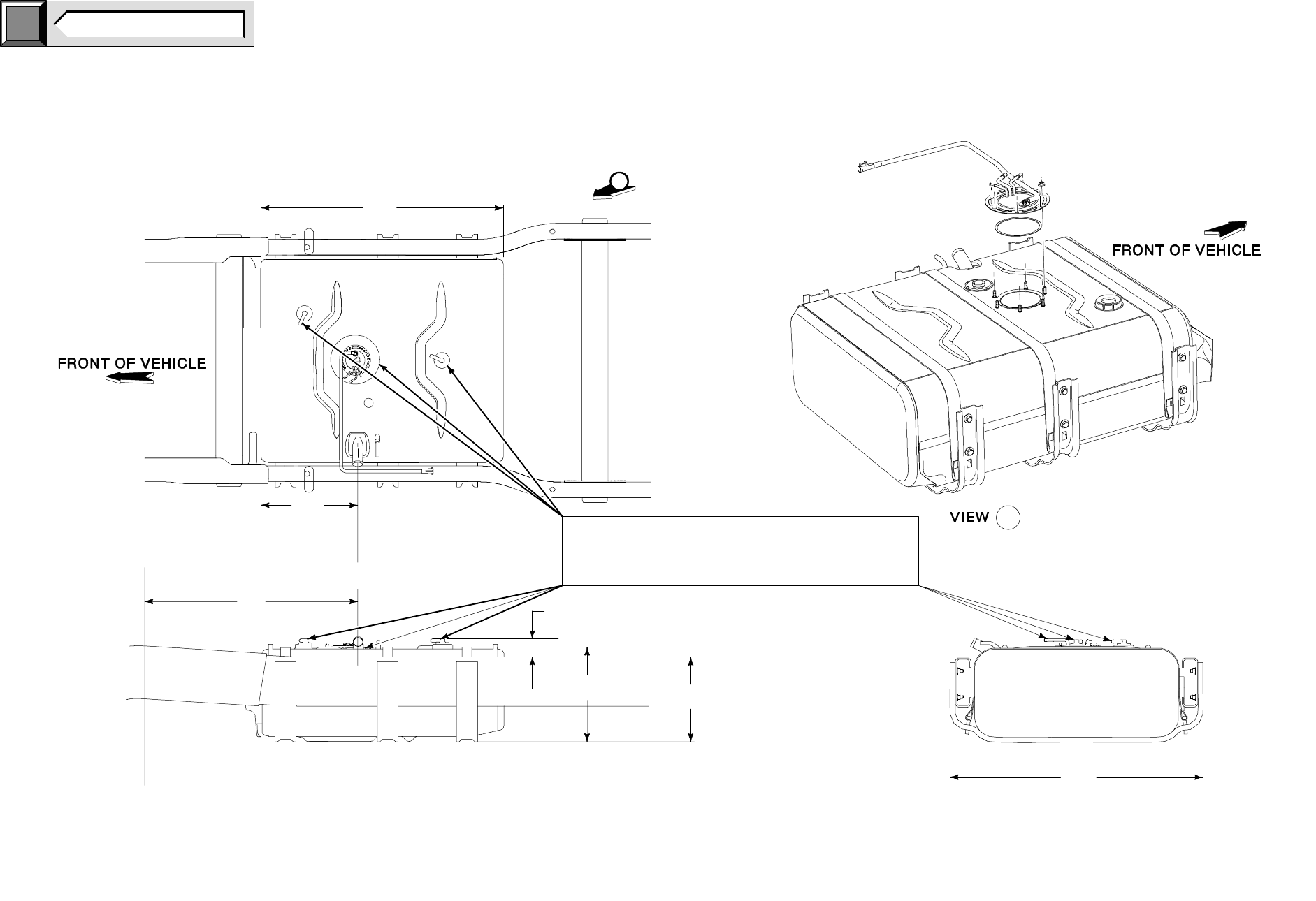
E-550 SUPER DUTY CUTAWAY
55 GALLON AFT-OF-AXLE FUEL TANK
NOTE [ ] DIMENSIONS ARE INCHES.
BB0693
822.9
[14.3] [13.0]
40.6
988.0
REAR AXLE
C
L
A
A
A
FUEL FILL
C
L
374.6
[14.7]
939.8
[37.0]
[32.4] [1.6]
363.2 330.2
[38.9]
25mm CLEARANCE IS REQUIRED BETWEEN
ALL FUEL TANK COMPONENTS AND
SECOND UNIT BODY. CONTACT BODY BUILDERS
ADVISORY SERVICE FOR INFORMATION.
click
here TO RETURN TO INDEX
Page 16 E-550 SUPER DUTY CUTAWAY
NOTE [ ] DIMENSIONS ARE INCHES.
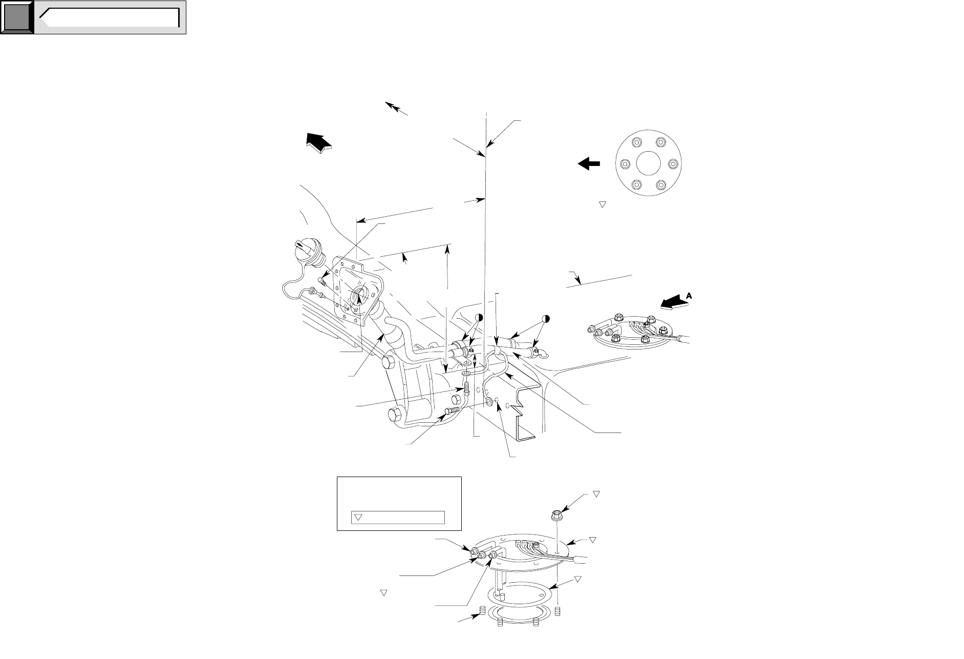
E-550 SUPER DUTY CUTAWAY
FUEL FILLER SYSTEMS
click
here TO RETURN TO INDEX
Page 17 E-550 SUPER DUTY CUTAWAY
1
2
3
4
5
6
FRONT OF
VEHICLE
TORQUE SEQUENCE
C
L OF FILLER NECK
OUTBOARD SURFACE
OF FRAME RAIL
FRONT OF VEHICLE
FUEL TANK
TO L OF REAR
AXLE FOR
ALL W.B.
C
SCREW 3 REQ’D.
TORQUE TO 2.1 – 2.9 Nm
18 – 26 IN LB.
TOP OF
FILLER
PIPE
SUPPORT SECURE WITH TIE
STRAPS AS REQUIRED
TO VENT HOSE
ROUTE FILL AND VENT
HOSE SO NO LOW
SPOTS OCCUR
9A099
GROUND STRAP
FUEL TANK
EXISTING 9.7 DIA. HOLES
(USED FOR EXHAUST
ON R.H. SIDE)
NUT 6 REQ’D.
TORQUE TO
13.7 – 17.3 Nm
120 – 153 IN LB.
FUEL PUMP/FUEL GAUGE
SENDING UNIT
NOTE: USE A NEW O–RING
GASKET WHEN REINSTALLING
THE FUEL PUMP/FUEL GAGE
SENDING UNIT.
FUEL TANK STUDS
AUXILIARY FUEL SUPPLY
(DO NOT REMOVE CAP
IF NOT IN USE)
FUEL SUPPLY
LINE
FUEL RETURN
CRITICAL CONTROL ITEM
TORQUE ALL WORM GEAR DRIVEN
HOSE CLAMPS TO 2.8 - 4.3 Nm
25 – 38 IN LBS.
N611645–S36
M10 SELF–TAPPING SCREW
(ATTACH TO SOUND
METAL ON FRAME)
N611131–S36
M4 SELF–TAPPING
SCREW
FUEL TANK
FILL PIPE
POINT Z SEE PAGE 59
OF THE INCOMPLETE
VEHICLE MANUAL
VIEW A
E-550 CUTAWAY
AFT-OF-AXLE FUEL FILLER SYSTEM
BB0678
823
[32.4]
733.4
[28.875]
323.2
[12.72]
40.2
[1.583]
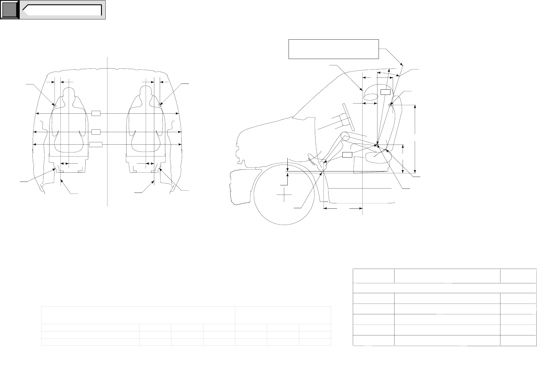
E-550 SUPER DUTY CUTAWAY
DIMENSIONAL DATA
E
B
B
E
W3
W5
W117
C
LOUTSIDE
FRONT
FASTENER
C
LOUTSIDE
FRONT
FASTENER
SEAT
BASE
POINT A
SEAT
BASE
POINT A
PASSENGER – SEAT DRIVER – SEAT
IMPORTANT:
THE DIMENSIONS IN THIS FIGURE REQUIRE THE VEHICLE TO BE AT
DESIGN POSITION. E–SERIES VEHICLES AT DESIGN POSITION
WILL BE LEVEL FRONT TO REAR, AND SIDE TO SIDE, ON THE UPPER
SURFACE OF THE RIBBED FLOOR PANEL FROM THE B–PILLAR REARWARD.
TORSO ANGLE
OUTSIDE
FRONT
FASTENER
POINT A
SEAT BACK
PIVOT
HEEL
POINT
A
D
THE TORSO ANGLE IS DETERMINED BY
USING THE METHOD SPECIFIED IN
SAE J826 (MAY 1987)
C
L
H61
L34
DRIVER SIDE ONLY
F
C
510.0
HIP ROOM – FRONT
EFFECTIVE HEAD ROOM – FRONT
MAXIMUM EFFECTIVE LEG ROOM – FRONT
SHOULDER ROOM – FRONT
H61
L34
W3
W5
CODE DESCRIPTION
FRONT COMPARTMENT
W117 BODY WIDTH AT H–POINT
1015 [39.9]
1736 [68.3]
BB0686
C
LVEHICLE
18 DRIVER
21 PASSENGER
DIMENSIONS
[20.08]
6.0
[0.24]
1666 [65.6]
1999 [78.7]
1079 [42.5]
SgRP - HAS A 12.7 [0.50] RADIAL
TOLERANCE PERMITTED FROM
BASE SgRP
NOTE [ ] DIMENSIONS ARE INCHES.
click
here TO RETURN TO INDEX
Page 18 E-550 SUPER DUTY CUTAWAY
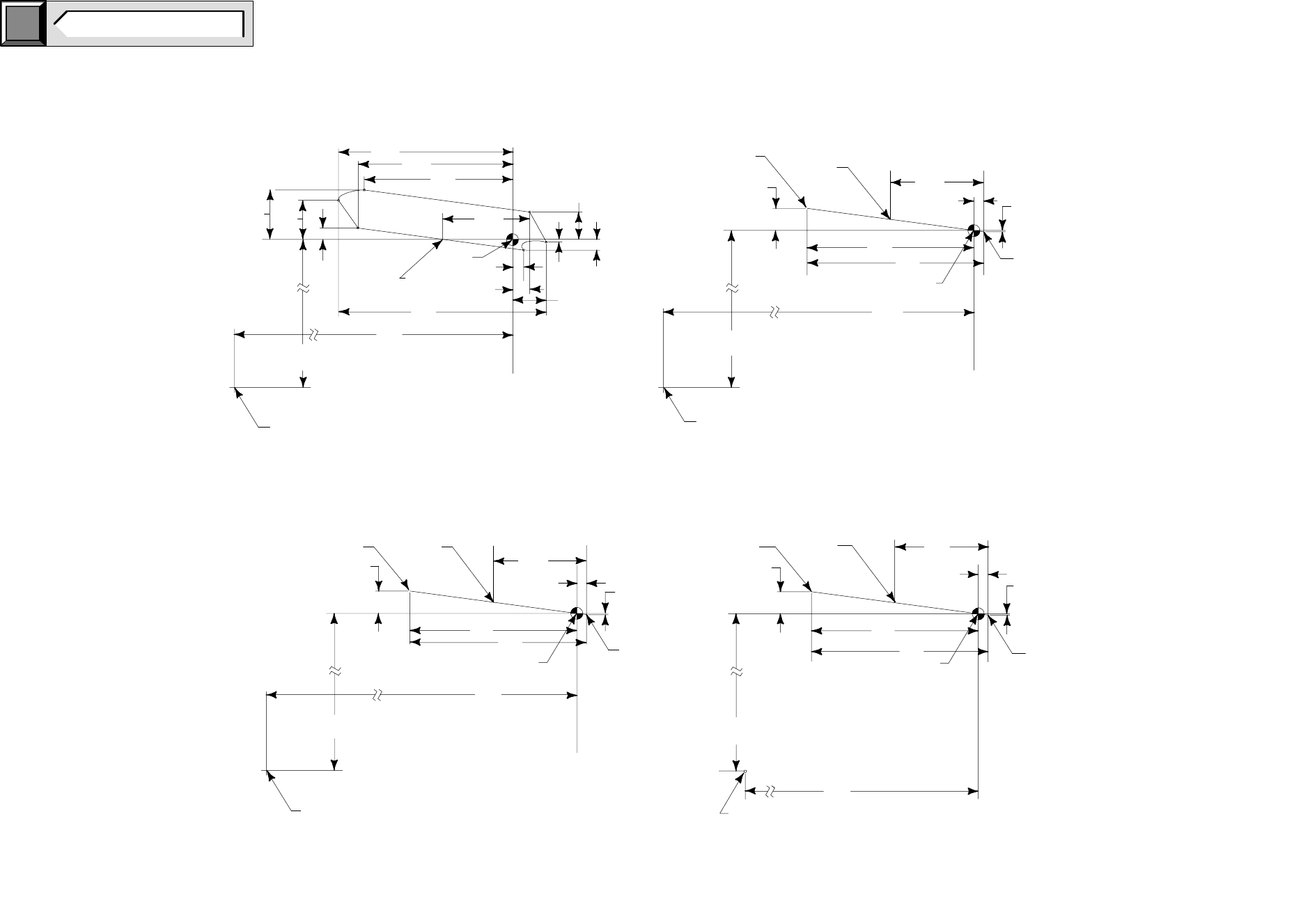
SgRP INFORMATION
(SEAT POSITION IS 10.0 [0.39] FORWARD OF
REARMOST POSITION)
POINT A
(SEAT POSITION IS AT THE MIDPOINT OF
AVAILABLE TRAVEL)
A B C D E F
DRIVER - SEAT (CUTAWAY) 217.8 [8.57] 105.0 [4.13] 384.2 [15.13] 356.0 [14.01] 67.0 [2.64] 937.4 [36.90]
PASSENGER - SEAT (CUTAWAY) 277.3 [10.92] 103.0 [4.06] 377.0 [14.84] 412.0 [16.22] 65.0 [2.56] 960.0 [37.80]
NOTE DIMENSIONS ARE INCHES.
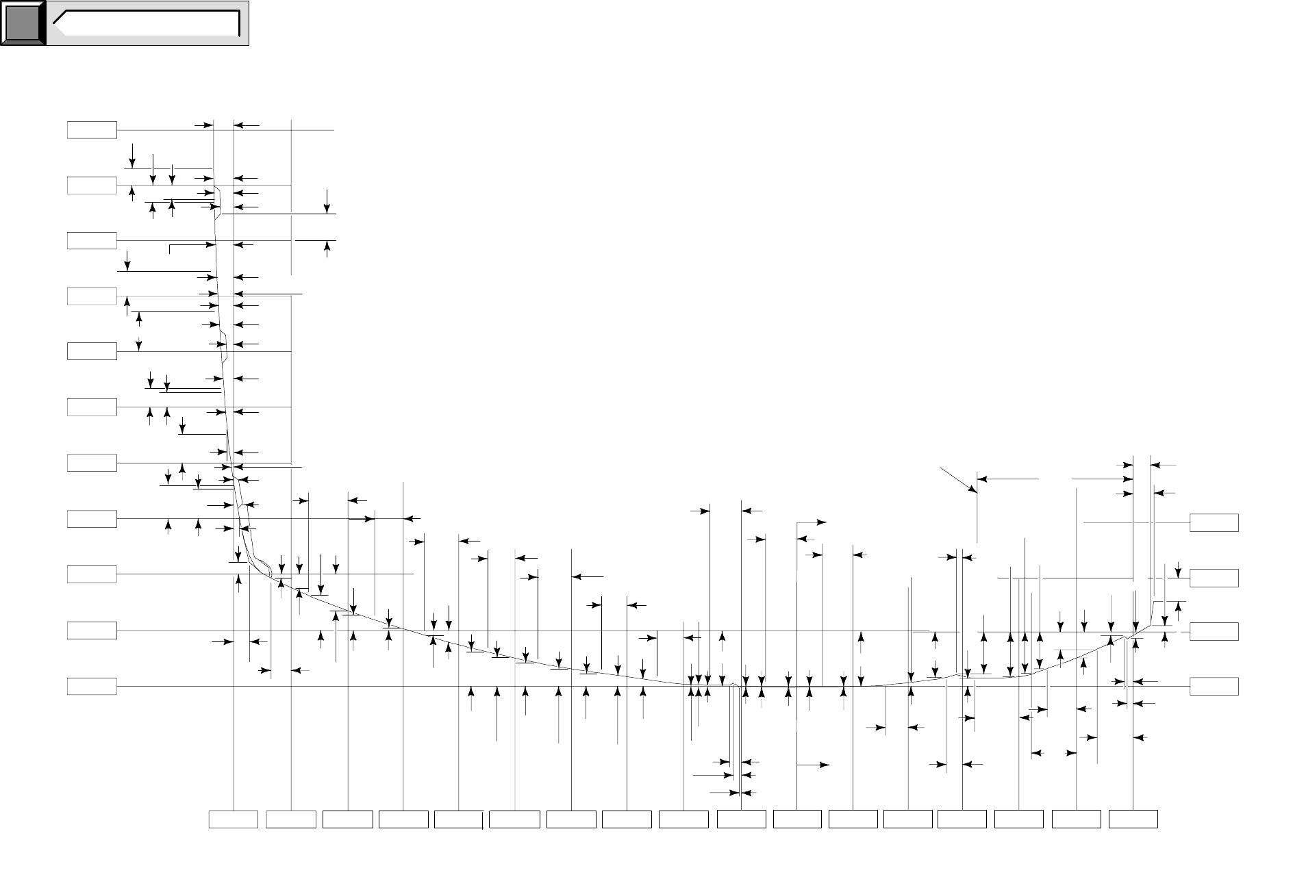
E-550 SUPER DUTY CUTAWAY
BODY “SECTION A”
51.1855.1259.0563.066.9370.3774.8078.7482.68
39.37
35.43
31.50
0.22
1.97
1.97
1.97
1.97
1.97
1.91
0.53
0.59
0.21 2.30
0.90
1.14
1.26
0.81
2.38
0.87
0.22
1.14
0.40
2.48
2.03
1.61 0.92
1.25 0.65
0.40
BB0671
27.56
23.62
19.68
15.75
11.81
7.87
3.94
0
1.97
1.97
1.97
1.97
1.97
1.97
1.97
1.03
0.40
0.35
0.44
0.59
0.27
0.07
0.20
1.00
0.92
0.83
0.75
1.16
1.20
1.18
1.16
1.16
0.77
0.35
C
LOF VEHICLE
39.37
35.43
31.50
27.56
47.24 43.30 39.37 35.43 31.50 23.62 19.68
3.84
0.02
1.97
1.97
1.97
1.97
1.97
1.97
1.97
A
0.04
0.03 0.09
0.66
0.07
0.08
3.70
TOP OF FRAME
0.08 0.02
0.25
3.23
3.07
1.12
9.45
3.17
3.01
3.31
1.53
0.53
2.64
0.94
0.49
0.36
2.11
1.36
0.44
0.29
0.41
A
3.03
27.56
SPACERS
1.85
0.41
0.18
NOTE DIMENSIONS SHOWN ARE INCHES.
click
here TO RETURN TO INDEX
Page 19 E-550 SUPER DUTY CUTAWAY
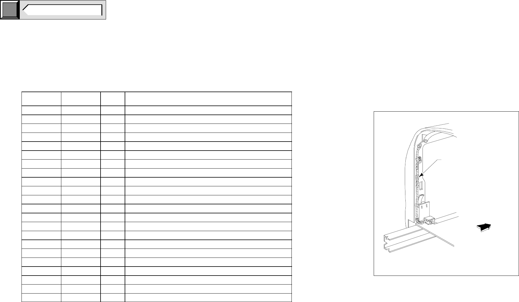
CIRCUIT CHART
ELECTRICAL WIRING
CUSTOMER ACCESS CIRCUITS
BB0481
UNWRAP TAPE FROM
HARNESS IN THIS AREA
AND REMOVE JUMPER
CONNECTION TO EXPOSE
FRONT OF
VEHICLE
TO INSTALL
THE “CHMSL CONNECTOR” .
“CHMSL”
FIGURE A
E-SERIES SUPER DUTY CUTAWAY
click
here TO RETURN TO INDEX
Page 20 E-550 SUPER DUTY CUTAWAY
Circuit
Number Color Code Wire
Gauge Functional Description
14 BR 18 Marker lamp feed to electric brake controller
43 DB 12 Electric trailer brake controller to trailer
49 OG 12 Relay feed ignition run
22 LB/BK 12 Trailer brake controller or B+ feed
52 YE 16 Fused left hand stop/turn
64 DG 16 Fused right hand stop/turn
206 W 16 Ground
511 LG 18 Center high mount or lamp feed stop
962 BR/W 16 Relay feed marker lamps
963 BK/LG 16 Relay feed backup lamp
867 DB 12 Customer pass thru circuits
868 GY/R 12 Customer pass thru circuits
53 BK/LB 18 Courtesy lamps
54 LG/YE 18 Courtesy switch feed
3 LG/WH 18 Left turn signal
2 WH/LB 18 Right turn signal
37 YE 12 Battery feed
517 BK/WH 12 Fused feed
751 DB/W 12 Aux. Sw. med hi
752 YE/RD 12 Aux. Sw. med lo
754 LG/WH 12 Aux. Sw. RR Con
757 RD/WH 18 Aux. Sw. hi
