Fortinet 220101 FORTIAP-220A User Manual FortiAP 200A QuickStart Guide
Fortinet Inc. FORTIAP-220A FortiAP 200A QuickStart Guide
Fortinet >
User Manual
QuickStart Guide
© Copyright 2010 Fortinet Incorporated. All rights reserved.
Products mentioned in this document are trademarks or registered trademarks
of their respective holders.
Regulatory Compliance
FCC Class A Part 15, / CE Mark
11 March 2010
FortiAP-220A
01-430-120928-2010011
Visit these links for more information and documentation for your Fortinet product:
Technical Documentation - http://docs.fortinet.com Fortinet Knowledge Center - http://kb.fortinet.com
Technical Support - http://support.fortinet.com Training Services - http://campus.training.fortinet.com
If the FortiGate wireless controller IP address cannot be determined
from the methods above or if the network uses static IP addresses, do
the following:
1. Connect the FortiAP to a separate private switch or hub or directly
connect to your computer via a cross-over cable.
2. Telnet to IP address 192.168.1.2
3. Login with username: root and no password.
4. Type the following command to enter static IP address for Access
Point
<enter command here>
5. Type the following command to enter the static IP address of Forti-
Gate Wireless Controller
<enter command here>
6. Exit from command line and move the FortiAP to the intended de-
ployment location and connect Ethernet cable as described above.
7. In Web Cong, go to Wireless Controller > Physical AP > Managed
Physical AP. Look for the name or serial number of the newly con-
nected unit.
8. In the Mode eld, select Enable.
9. Select a FortiAP prole from the list and click OK.
10. The conguration is downloaded from the FortiGate unit to the For-
tiAP and the Wireless LED lights up.
Note: FortiGate Low encryption units must be matched up with Low
Encryption Access Points.
Conguring continued...
Power Required Adaptor Input 100-240V~ 50/60Hz 0.6A
Output: 12V DC 1.5A –center positive
Dimensions 1.1 in (2.7 cm) x 6.4 in (16.3 cm) x 5.1 in (12.9 cm)
Ethernet port 1 x 10/100
Indoor/outdoor deployment Indoor
Mount Wall or ceiling
Federal Communication Commission Interference Statement
This equipment has been tested and found to comply with the limits for a Class B digital device, pursuant to
Part 15 of the FCC Rules. These limits are designed to provide reasonable protection against harmful interfer-
ence in a residential installation. This equipment generates, uses and can radiate radio frequency energy
and, if not installed and used in accordance with the instructions, may cause harmful interference to radio
communications. However, there is no guarantee that interference will not occur in a particular installation. If
this equipment does cause harmful interference to radio or television reception, which can be determined by
turning the equipment off and on, the user is encouraged to try to correct the interference by one of the follow-
ing measures:
• Reorient or relocate the receiving antenna.
• Increase the separation between the equipment and receiver.
• Connect the equipment into an outlet on a circuit different from that to which the receiver is connected.
• Consult the dealer or an experienced radio/TV technician for help.
FCC Caution: Any changes or modications not expressly approved by the party responsible for compliance
could void the user’s authority to operate this equipment.
For operation within 5.15 ~ 5.25GHz frequency range, it is restricted to indoor environment.
This device complies with Part 15 of the FCC Rules. Operation is subject to the following two conditions: (1)
This device may not cause harmful interference, and (2) this device must accept any interference received,
including interference that may cause undesired operation.
IMPORTANT NOTE: Radiation Exposure Statement
This equipment complies with FCC radiation exposure limits set forth for an uncontrolled environment. This
equipment should be installed and operated with minimum distance 20cm between the radiator & your body.
This transmitter must not be co-located or operating in conjunction with any other antenna or transmitter.
The availability of some specic channels and/or operational frequency bands are country dependent and are
rmware programmed at the factory to match the intended destination. The rmware setting is not accessible
by the end user.
Industry Canada Statement
This device complies with RSS-210 of the Industry Canada Rules. Operation is subject to the following two
conditions: (1) This device may not cause harmful interference, and (2) this device must accept any interference
received, including interference that may cause undesired operation.
Règlement d’Industry Canada
Les conditions de fonctionnement sont sujettes à deux conditions:
1) Ce périphérique ne doit pas causer d’interférence et.
2) Ce périphérique doit accepter toute interférence, y compris les interférences pouvant perturber le bon fonc-
tionnement de ce périphérique.
IMPORTANT NOTE: Radiation Exposure Statement
This equipment complies with IC radiation exposure limits set forth for an uncontrolled environment. This equip-
ment should be installed and operated with minimum distance 20cm between the radiator & your body.
Caution:
The device for the band 5150-5250 MHz is only for indoor usage to reduce potential for harmful interference to
co-channel mobile satellite systems.
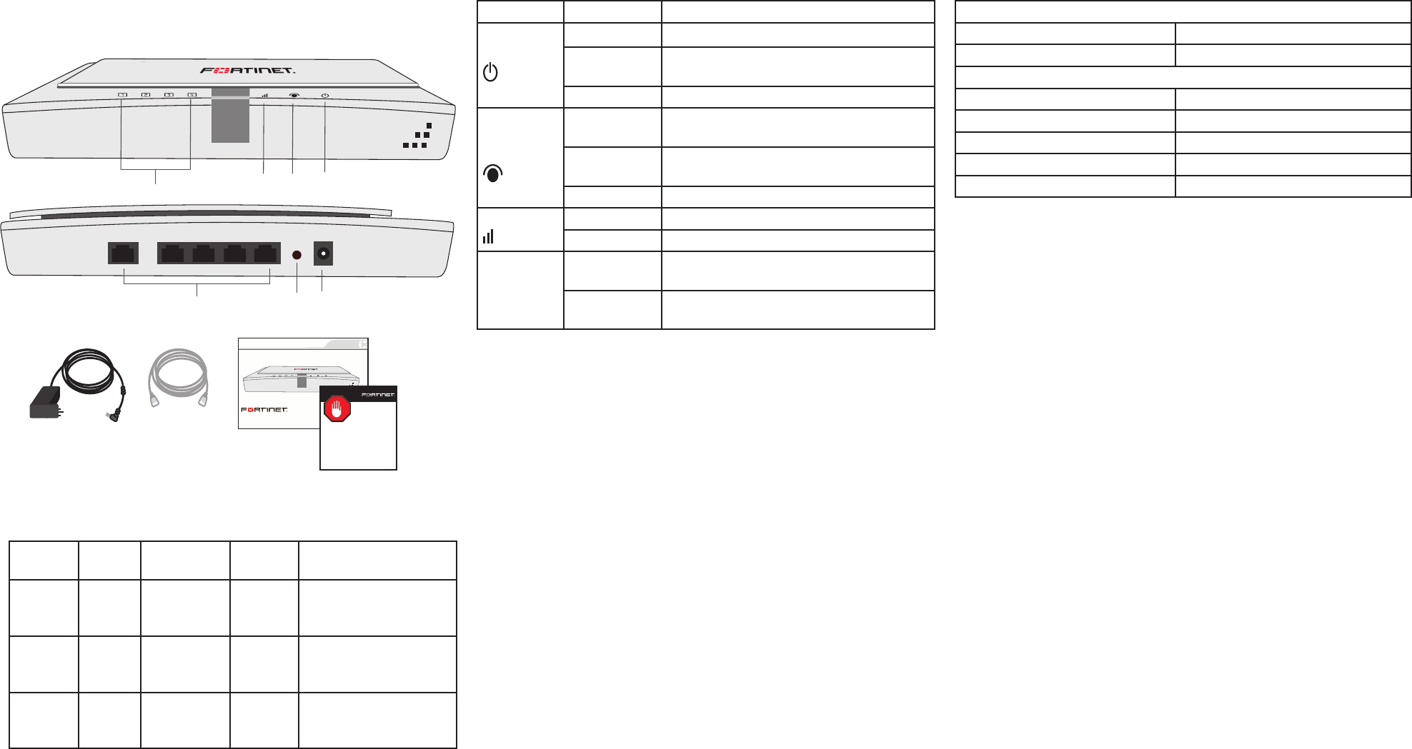
LED DescriptionPackage Contents
PORT 0 PORT 1 PORT 2 PORT 3 PORT 4
RESET POWER
Port 1 to 4 LEDs Wireless
LED
Port 0
LED
Power
LED
Ports 0 to 4 Reset
button
Power
button
Front
Back
Interface Description
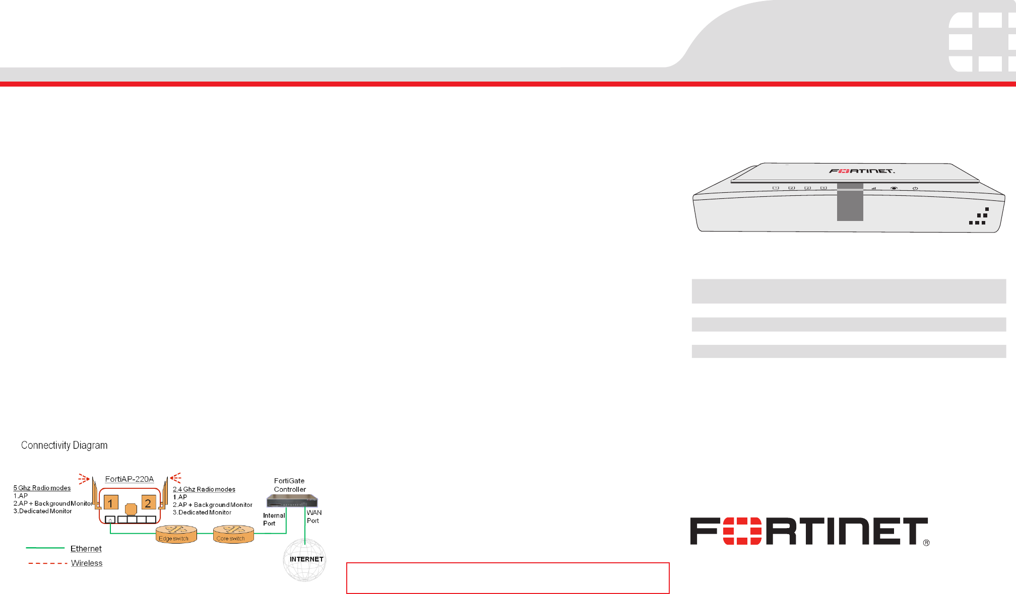
Connecting
Administrator login
Username admin
Password <none>
Default port addresses
Port 0 192.168.1.2
Port 1 Do not use
Port 2 Do not use
Port 3 Do not use
Port 4 Do not use
Straight-through
Ethernet cable
FortiGate-3 0B
Copyright 2010 Fortinet Incorporated. All rights reserved.
Trademarks
Products mentioned in this document are trademarks.
QuickStart Guide
Power Supply
REGISTER
Factory Defaults
LED State Description
Power
Green The unit is on.
Green Flash-
ing
The unit is starting up.
Off The unit is off.
Ethernet
Port 0
Green The correct cable is in use and Ethernet
connectivity is established.
Green Flash-
ing
The port is sending or receiving data
(activity)
Off No link.
Wireless Green At least one wireless radio is enabled.
Off Both wireless radios are disabled.
Port 1 to 4
Green Port is connected. This condition is not
recommended.
Off Port is not connected. This is the desired
state.
Inter-
face
Type Speed Proto-
col
Description
PORT 0 RJ-45 10/100
Base-T
Ethernet Use this port as the
primary connection to
the LAN
PORT 1
to PORT
4
RJ-45 10/100
Base-T
Ethernet Do not use these
ports.
Reset
button
Hold for 5 seconds to
reset the FortiAP unit
to its factory defaults.
Using the provided template and two M3 screws, attach the unit to the
wall or ceiling using the two mounting holes at the bottom of the FortiAP
unit. If placing on desktop, attach the rubber feet to the unit.
Connect the following to the FortiAP unit:
1. Insert a network cable to Port 0.
• Use straight-through cable for most equipment
• Use cross-over cable if connecting to FortiGate units without
auto MDI detect
2. Insert the other end of the network cable into your LAN Ethernet
edge switch, or directly to the FortiGate Controller.
3. Connect the power adaptor to AC outlet.
4. Insert the power adaptor connector to the FortiAP unit.
Note: The FortiAP-220A does not support 802.3af POE therefore AC
power connection is mandatory. Use only the supplied power adaptor.
Substitution of power adaptor can damage the system and voids your
warranty.
Conguring
The FortiAP is designed to require no conguration in most networks.
Zero Conguration mode works if the FortiAP is directly connected to the
FortiGate performing the Wireless LAN Controller (WLC) functions, or
on the same layer-2 network and subnet as the FortiGate.
To enable the FortiAP using Zero Conguration:
1. Connect the network and power cable as described in the Connect-
ing section.
2. Once power is applied, the FortiAP goes through boot procedure
and requests an IP address from the DHCP server.
3. If the IP address is retrieved successfully, the FortiAP enters dis-
covery mode to locate a FortiGate wireless controller. The discovery
modes are:
• Broadcast
• Multicast
• DHCP option 138
4. If this is the rst time connecting the FortiAP to the controller, only
the power light and Port 0 LED is lit. If the FortiAP has been pre-
provisioned in the controller, the Wireless LED is also lit.
5. Verify that the FortiAP has successfully connected to the controller.
In Web Cong, go to Wireless Controller > Physical AP > Managed
Physical AP. Look for the name or serial number of the newly con-
nected unit.
6. In the Mode eld, select Enable.
7. Select a FortiAP prole from the list and click OK.
8. The conguration is downloaded from the FortiGate unit to the For-
tiAP and the Wireless LED lights up.