Contents
- 1. User Manual Part One
- 2. User Manual Part Two
User Manual Part One

www.fortinet.com
FortiGate-50A/50B,
FortiWiFi-50B and
FortiGate-100
FortiOS 3.0 MR4
INSTALL GUIDE

FortiGate-50A/50B, FortiWiFi-50B and FortiGate-100 Install Guide
FortiOS 3.0 MR4
22 May 2007
01-30004-0265-20070522
© Copyright 2007 Fortinet, Inc. All rights reserved. No part of this
publication including text, examples, diagrams or illustrations may be
reproduced, transmitted, or translated in any form or by any means,
electronic, mechanical, manual, optical or otherwise, for any purpose,
without prior written permission of Fortinet, Inc.
Trademarks
Dynamic Threat Prevention System (DTPS), APSecure, FortiASIC,
FortiBIOS, FortiBridge, FortiClient, FortiGate, FortiGate Unified Threat
Management System, FortiGuard, FortiGuard-Antispam, FortiGuard-
Antivirus, FortiGuard-Intrusion, FortiGuard-Web, FortiLog, FortiAnalyzer,
FortiManager, Fortinet, FortiOS, FortiPartner, FortiProtect, FortiReporter,
FortiResponse, FortiShield, FortiVoIP, and FortiWiFi are trademarks of
Fortinet, Inc. in the United States and/or other countries. The names of
actual companies and products mentioned herein may be the trademarks
of their respective owners.
Regulatory compliance
FCC Class A Part 15 CSA/CUS
!
Caution: Risk of Explosion if Battery is replaced by an Incorrect Type.
Dispose of Used Batteries According to the Instructions.

Contents
FortiGate-50A/50B, FortiWiFi-50B and FortiGate-100 FortiOS 3.0 MR4 Install Guide
01-30004-0265-20070522 3
Contents
Contents.............................................................................................. 3
Introduction ........................................................................................ 7
About the FortiGate unit ................................................................................... 7
FortiGate-50A................................................................................................ 7
FortiGate-50B................................................................................................ 8
FortiWiFi-50B ................................................................................................ 8
FortiGate-100 ................................................................................................ 8
Register your FortiGate unit .......................................................................... 8
Fortinet Family Products .................................................................................. 9
FortiGuard Subscription Services ................................................................. 9
FortiClient...................................................................................................... 9
FortiMail ........................................................................................................ 9
FortiAnalyzer ............................................................................................... 10
FortiReporter ............................................................................................... 10
FortiBridge................................................................................................... 10
FortiManager............................................................................................... 10
About this document....................................................................................... 10
Document conventions................................................................................ 11
Typographic conventions...................................................................... 11
Fortinet documentation .................................................................................. 12
Fortinet Tools and Documentation CD........................................................ 13
Fortinet Knowledge Center ........................................................................ 13
Comments on Fortinet technical documentation ........................................ 13
Customer service and technical support ...................................................... 13
Installing the FortiGate unit ............................................................ 15
Package Contents............................................................................................ 15
FortiGate-50A.............................................................................................. 15
FortiGate-50B.............................................................................................. 16
FortiWiFi-50B .............................................................................................. 17
FortiGate-100 .............................................................................................. 17
Warnings ..................................................................................................... 18
Mounting........................................................................................................... 19
Powering on the FortiGate unit ...................................................................... 19
Power over Ethernet ................................................................................... 20
Powering off the FortiGate unit ...................................................................... 20

FortiGate-50A/50B, FortiWiFi-50B and FortiGate-100 FortiOS 3.0 MR4 Install Guide
401-30004-0265-20070522
Contents
Connecting to the FortiGate unit ................................................................... 20
Web-based manager .................................................................................. 21
Command line interface .............................................................................. 21
Connecting to the web-based manager ...................................................... 21
Command line interface .............................................................................. 22
Connecting to the CLI ................................................................................. 23
Quick installation using factory defaults ...................................................... 24
Factory defaults ............................................................................... 27
Factory default DHCP server configuration ................................................ 28
Factory default NAT/Route mode network configuration ............................ 28
Factory default Transparent mode network configuration........................... 29
Factory default firewall configuration .......................................................... 29
Factory default protection profiles............................................................... 30
Restoring the default settings........................................................................ 31
Restoring the default settings using the web-based manager .................... 31
Restoring the default settings using the CLI ............................................... 31
Configuring the FortiGate unit........................................................ 33
Planning the FortiGate configuration ............................................................ 33
NAT/Route mode ........................................................................................ 33
NAT/Route mode with multiple external network connections .................... 34
Transparent mode....................................................................................... 35
Preventing the public interface from responding to ping requests ........... 35
NAT/Route mode installation ......................................................................... 36
Preparing to configure the FortiGate unit in NAT/Route mode ................... 36
DHCP or PPPoE configuration ................................................................... 37
Using the web-based manager ................................................................... 37
Configuring basic settings .................................................................... 37
Adding a default route .......................................................................... 38
Verifying the web-based manager configuration .................................. 39
Verify the connection ............................................................................ 39
Using the command line interface............................................................... 39
Configuring the FortiGate unit to operate in NAT/Route mode............. 39
Adding a default route .......................................................................... 41
Connecting the FortiGate unit to the network(s) ......................................... 42
Configuring the networks ............................................................................ 42
Transparent mode installation ....................................................................... 43
Preparing to configure Transparent mode .................................................. 43
Using the web-based manager ................................................................... 43
Using the command line interface............................................................... 44
Connecting the FortiGate unit to your network ........................................... 45

FortiGate-50A/50B, FortiWiFi-50B and FortiGate-100 FortiOS 3.0 MR4 Install Guide
501-30004-0265-20070522
Contents
Next steps ........................................................................................................ 46
Set the date and time.................................................................................. 46
Updating antivirus and IPS signatures ........................................................ 47
Updating antivirus and IPS signatures from the web-based manager . 47
Updating the IPS signatures from the CLI ............................................ 48
Scheduling antivirus and IPS updates.................................................. 48
Adding an override server .................................................................... 49
Configuring the modem interface .................................................. 51
Connecting a modem to the FortiGate-50A .................................................. 51
Selecting a modem mode ............................................................................... 52
Redundant mode configuration................................................................... 52
Stand alone mode configuration ................................................................. 52
Configuring the modem for the FortiGate-50A............................................. 53
Adding a Ping Server ...................................................................................... 55
Dead gateway detection ............................................................................. 55
Adding firewall policies for modem connections......................................... 56
Using a wireless network ................................................................ 57
Setting up a wireless network ........................................................................ 57
Positioning an Access Point........................................................................ 58
Radio Frequency interface.......................................................................... 58
Using multiple access points....................................................................... 59
Wireless Security............................................................................................. 60
Wireless Equivalent Privacy (WEP) ............................................................ 60
Wi-Fi Protected Access (WPA) ................................................................... 60
Additional security measures ...................................................................... 61
MAC address filtering ........................................................................... 61
Service Set Identifier ............................................................................ 61
FortiWiFi-50B operation modes ..................................................................... 61
Access Point mode ..................................................................................... 61
Client mode................................................................................................. 62
Changing the operating mode .............................................................. 63
Setting up the FortiWiFi-50B as an Access Point ........................................ 63
Set the DHCP settings ................................................................................ 63
Set the security options............................................................................... 64
Configure the firewall policies ..................................................................... 64
FortiGate Firmware .......................................................................... 65
Upgrading to a new firmware version ........................................................... 65
Upgrading the firmware using the web-based manager ............................. 65
Upgrading the firmware using the CLI ........................................................ 66

FortiGate-50A/50B, FortiWiFi-50B and FortiGate-100 FortiOS 3.0 MR4 Install Guide
601-30004-0265-20070522
Contents
Reverting to a previous firmware version..................................................... 67
Reverting to a previous firmware version using the web-based manager .. 67
Reverting to a previous firmware version using the CLI ............................. 68
Installing firmware images from a system reboot using the CLI ................ 70
Restoring the previous configuration .......................................................... 72
The FortiUSB key............................................................................................. 73
Backup and Restore from the FortiUSB key ............................................... 73
Using the USB Auto-Install feature ............................................................. 74
Additional CLI commands for the FortiUSB key.......................................... 75
Testing a new firmware image before installing it ....................................... 75
Installing and using a backup firmware image............................................. 77
Installing a backup firmware image............................................................. 77
Index.................................................................................................. 81
Introduction About the FortiGate unit
FortiGate-50A/50B, FortiWiFi-50B and FortiGate-100 FortiOS 3.0 MR4 Install Guide
01-30004-0265-20070522 7
Introduction
Welcome and thank you for selecting Fortinet products for your real-time network
protection.
FortiGate™ Unified Threat Management System improves network security,
reduces network misuse and abuse, and helps you use communications
resources more efficiently without compromising the performance of your
network. FortiGate Unified Threat Management Systems are ICSA-certified for
firewall, IPSec, and antivirus services.
The FortiGate Unified Threat Management System is a dedicated, easily
managed security device that delivers a full suite of capabilities, which include:
• application-level services such as virus protection and content filtering
• network-level services such as firewall, intrusion detection, VPN and traffic
shaping
The FortiGate Unified Threat Management System uses Fortinet’s Dynamic
Threat Prevention System (DTPS™) technology, which leverages breakthroughs
in chip design, networking, security and content analysis. The unique ASIC-based
architecture analyzes content and behavior in real-time, enabling key applications
to be deployed right at the network edge where they are most effective at
protecting your networks.
About the FortiGate unit
The FortiGate-50A/50B, FortiWiFi-50B and FortiGate-100 appliances are
designed for SOHO and SMB offices, to deliver the same enterprise-class
network-based antivirus, content filtering, firewall, VPN, and network-based
intrusion detection/prevention featured in all FortiGate units.
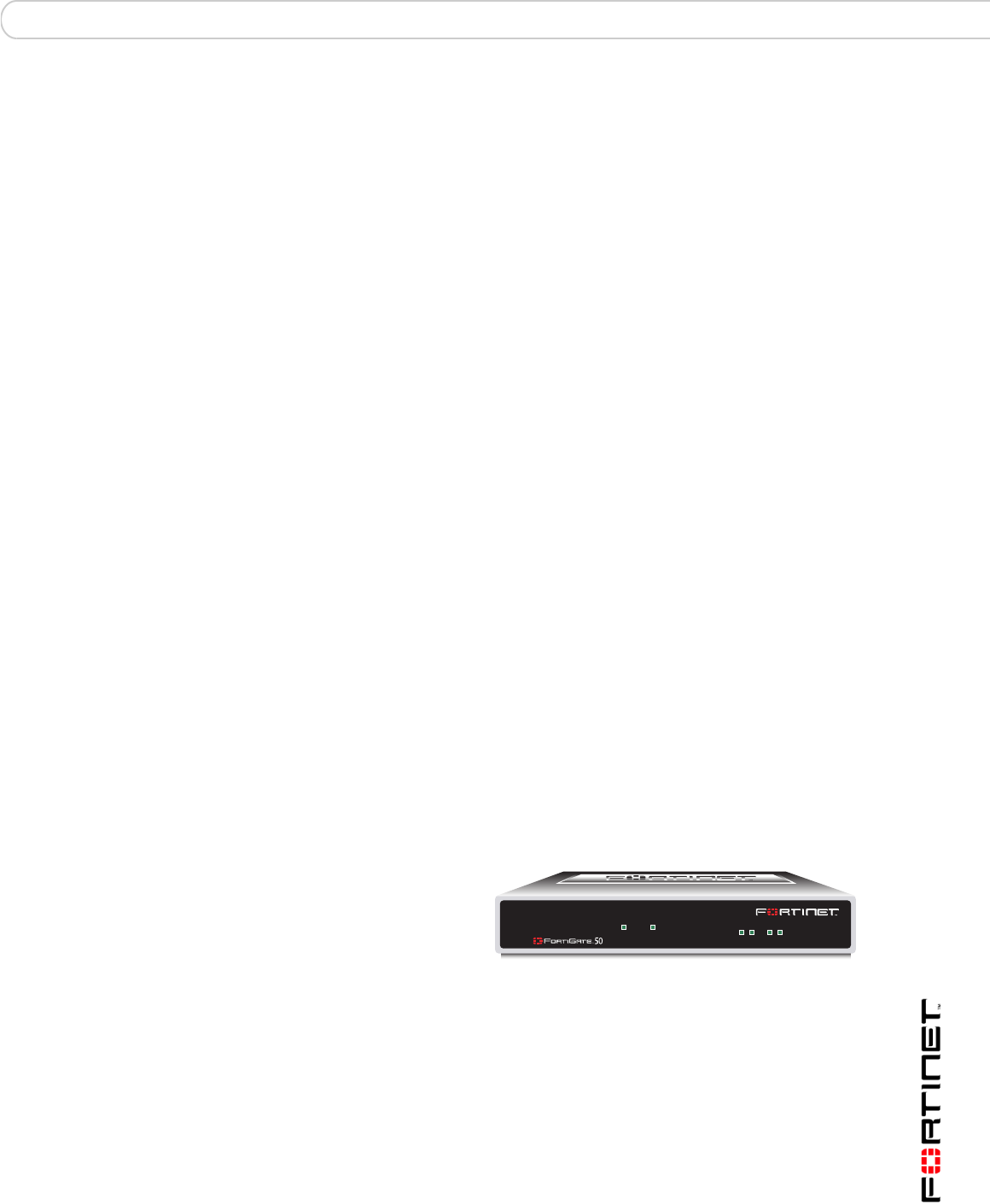
FortiGate-50A
The FortiGate-50A is
designed for telecommuters
and small remote offices with
10 or fewer employees. The
FortiGate-50A unit includes
an external modem port that
can be used as a backup or stand alone connection to the Internet.
INTERNAL EXTERNAL
LINK 100 LINK 100
PWR STATUS
AM
FortiGate-50A/50B, FortiWiFi-50B and FortiGate-100 FortiOS 3.0 MR4 Install Guide
801-30004-0265-20070522
About the FortiGate unit Introduction
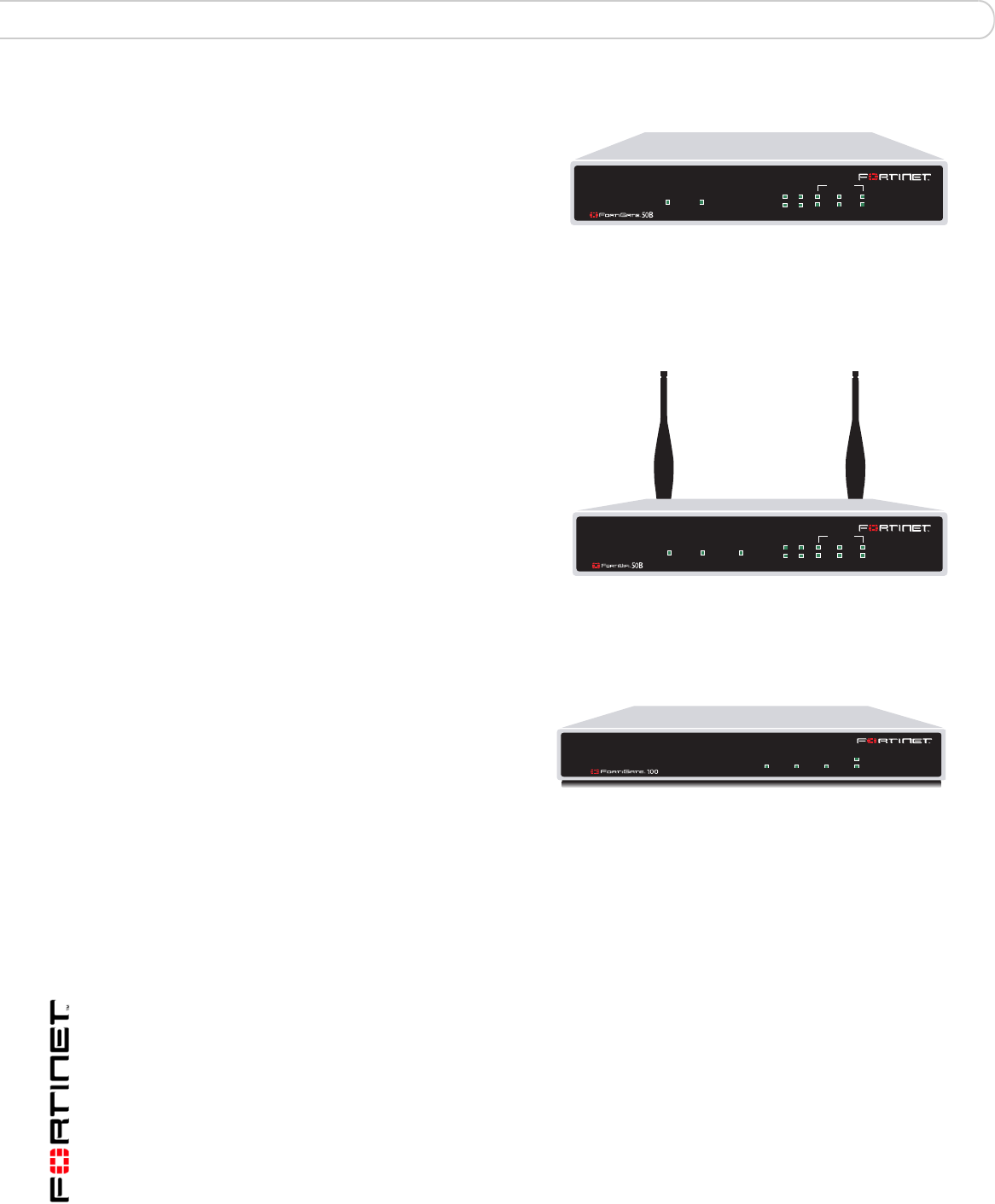
FortiGate-50B
The FortiGate-50B is
designed for telecommuters
and small remote offices with
10 to 50 employees. The
FortiGate-50B unit includes
two WAN ports for a
redundant connection to the Internet. It also features a 3-port switch for
connecting additional network connections and supports HA configurations with
additional FortiGate-50B units.
FortiWiFi-50B
The FortiWiFi-50B is
designed for telecommuters
and small remote offices with
10 to 50 employees. The
FortiWiFi-50B unit includes
two WAN ports for a
redundant connection to the
Internet. It also features a
3-port switch for connecting
additional network
connections and supports HA
configurations with additional
FortiWiFi-50B units. The FortiWiFi-50B includes Power over Ethernet (PoE)
capabilities as a Powered Device through the WAN1 port.
FortiGate-100
The FortiGate-100 unit is
designed for SOHO, SMB
and branch office
applications.
The FortiGate-100 supports
advanced features such as 802.1Q VLAN, virtual domains, high availability (HA),
and the RIP and OSPF routing protocols.
Register your FortiGate unit
Register your FortiGate unit by visiting http://support.fortinet.com and selecting
Product Registration.
To register, enter your contact information and the serial numbers of the FortiGate
units that you or your organization have purchased. You can register multiple
FortiGate units in a single session without re-entering your contact information.
By registering your FortiGate unit, you will receive updates to threat detection and
prevention databases (Antivirus, Intrusion Detection, etc.) and will also ensure
your access to technical support.
WAN1 WA N2
POWER STATUS
INTERNAL
321
LINK / ACT
10/100
WAN1 WA N2
POWER STATUS
INTERNAL
321
LINK / ACT
10/100
WLAN
(PoE)
INTERNAL EXTERNAL DMZ POWER
STATUS

Introduction Fortinet Family Products
FortiGate-50A/50B, FortiWiFi-50B and FortiGate-100 FortiOS 3.0 MR4 Install Guide
01-30004-0265-20070522 9
Fortinet Family Products
Fortinet offers a family of products that includes both software and hardware
appliances for a complete network security solution including mail, logging,
reporting, network management, and security along with FortiGate Unified Threat
Management Systems. For more information on the Fortinet product family, go to
www.fortinet.com/products.
FortiGuard Subscription Services
FortiGuard Subscription Services are security services created, updated and
managed by a global team of Fortinet security professionals. They ensure the
latest attacks are detected and blocked before harming your corporate resources
or infecting your end-user computing devices. These services are created with the
latest security technology and designed to operate with the lowest possible
operational costs.
FortiGuard Subscription Services includes:
• FortiGuard Antivirus Service
• FortiGuard Intrusion Prevention subscription services (IPS)
• FortiGuard Web Filtering
• FortiGuard Antispam Service
• FortiGuard Premier Service
An online virus scanner and virus encyclopedia is also available for your
reference.
FortiClient
FortiClient™ Host Security software provides a secure computing environment for
both desktop and laptop users running the most popular Microsoft Windows
operating systems. FortiClient offers many features including:
• creating VPN connections to remote networks
• configuring real-time protection against viruses
• guarding against modification of the Windows registry
• virus scanning
FortiClient also offers a silent installation feature, enabling an administrator to
efficiently distribute FortiClient to several users’ computers with preconfigured
settings.
FortiMail
FortiMail™ Secure Messaging Platform provides powerful, flexible heuristic
scanning and reporting capabilities to incoming and outgoing email traffic. The
FortiMail unit has reliable, high performance features for detecting and blocking
malicious attachments such as Distributed Checksum Clearinghouse (DCC)
scanning and Bayesian scanning. Built on Fortinet’s award winning FortiOS and
FortiASIC technology, FortiMail antivirus technology extends full content
inspection capabilities to detect the most advanced email threats.

FortiGate-50A/50B, FortiWiFi-50B and FortiGate-100 FortiOS 3.0 MR4 Install Guide
10 01-30004-0265-20070522
About this document Introduction
FortiAnalyzer
FortiAnalyzer™ provides network administrators with the information they need to
enable the best protection and security for their networks and monitor against
attacks and vulnerabilities. The FortiAnalyzer unit features include:
• collecting logs from FortiGate, FortiManager, FortiMail devices and syslog
devices
• generating reports on network use, vulnerabilities, and traffic patterns.
• storing quarantined files from a FortiGate unit and archived content from email
and IM conversations.
The FortiAnalyzer unit can also be configured as a network analyzer to capture
real-time traffic on areas of your network where firewalls are not employed. You
can also use the unit as a storage device where users can access and share files,
including the reports and logs that are saved on the FortiAnalyzer hard disk.
FortiReporter
FortiReporter™ Security Analyzer software generates easy-to-understand reports
and can collect logs from any FortiGate unit, as well as over 30 network and
security devices from third-party vendors. FortiReporter reveals network abuse,
manages bandwidth requirements, monitors web usage, and ensures employees
are using the office network appropriately. FortiReporter allows IT administrators
to identify and respond to attacks, including identifying ways to proactively secure
their networks before security threats arise.
FortiBridge
FortiBridge™ products are designed to provide enterprise organizations with
continuous network traffic flow in the event of a power outage or a FortiGate
system failure. The FortiBridge unit bypasses the FortiGate unit to ensure that the
network can continue processing traffic. FortiBridge products are easy to use and
deploy, and you can customize the actions a FortiBridge unit takes when a power
failure or a FortiGate system failure occurs.
FortiManager
The FortiManager™ system is designed to meet the needs of large enterprises
(including managed security service providers) responsible for establishing and
maintaining security policies across many dispersed FortiGate installations. With
this system, you can configure multiple FortiGate devices and monitor their status.
You can also view real-time and historical logs for the FortiGate devices, including
updating firmware images of managed FortiGate devices. The FortiManager
System emphasizes ease of use, including easy integration with third party
systems.
About this document
This document explains how to install and configure your FortiGate unit onto your
network. This document also includes how to install and upgrade new firmware
versions on your FortiGate unit.
Introduction About this document
FortiGate-50A/50B, FortiWiFi-50B and FortiGate-100 FortiOS 3.0 MR4 Install Guide
01-30004-0265-20070522 11
This document contains the following chapters:
•Installing the FortiGate unit – Describes unpacking, setting up, and powering
on a FortiGate unit.
•Factory defaults – Provides the factory default settings for the FortiGate unit
•Configuring the FortiGate unit – Provides an overview of the operating modes
of the FortiGate unit and how to integrate the FortiGate unit into your network.
•Configuring the modem interface – Describes how to configure and use a
modem with the FortiGate-50A and FortiGate-50AM units.
•Using a wireless network – Describes configuring a wireless network and
postioning the FortiWiFi-50B unit for best reception.
•FortiGate Firmware – Describes how to install, update, restore and test the
firmware for the FortiGate device.
Document conventions
The following document conventions are used in this guide:
• In the examples, private IP addresses are used for both private and public IP
addresses.
• Notes and Cautions are used to provide important information:
Typographic conventions
FortiGate documentation uses the following typographical conventions:
Note: This guide covers information on four FortiGate units; the FortiGate-50A,
FortiGate-50B, FortiWiFi-50B and FortiGate-100. While most of the content applies to all
the units, where information is specific to a certain model, an icon like the ones below will
appear next to the content.
50A 100
50B WiFi-50B
Note: Highlights useful additional information.
!
Caution: Warns you about commands or procedures that could have unexpected or
undesirable results including loss of data or damage to equipment.

FortiGate-50A/50B, FortiWiFi-50B and FortiGate-100 FortiOS 3.0 MR4 Install Guide
12 01-30004-0265-20070522
Fortinet documentation Introduction
Fortinet documentation
The most up-to-date publications and previous releases of Fortinet product
documentation are available from the Fortinet Technical Documentation web site
at http://docs.forticare.com.
The following FortiGate product documentation is available:
• FortiGate QuickStart Guide
Provides basic information about connecting and installing a FortiGate unit.
• FortiGate Install Guide
Describes how to install a FortiGate unit. Includes a hardware reference,
default configuration information, installation procedures, connection
procedures, and basic configuration procedures. Choose the guide for your
product model number.
• FortiGate Administration Guide
Provides basic information about how to configure a FortiGate unit, including
how to define FortiGate protection profiles and firewall policies; how to apply
intrusion prevention, antivirus protection, web content filtering, and spam
filtering; and how to configure a VPN.
• FortiGate online help
Provides a context-sensitive and searchable version of the Administration
Guide in HTML format. You can access online help from the web-based
manager as you work.
• FortiGate CLI Reference
Describes how to use the FortiGate CLI and contains a reference to all
FortiGate CLI commands.
•FortiGate Log Message Reference
Available exclusively from the Fortinet Knowledge Center, the FortiGate Log
Message Reference describes the structure of FortiGate log messages and
provides information about the log messages that are generated by FortiGate
units.
Convention Example
Keyboard input In the Gateway Name field, type a name for the remote VPN
peer or client (for example, Central_Office_1).
Code examples config sys global
set ips-open enable
end
CLI command syntax config firewall policy
edit id_integer
set http_retry_count <retry_integer>
set natip <address_ipv4mask>
end
Document names FortiGate Administration Guide
Menu commands Go to VPN > IPSEC > Phase 1 and select Create New.
Program output Welcome!
Variables <address_ipv4>

Introduction Customer service and technical support
FortiGate-50A/50B, FortiWiFi-50B and FortiGate-100 FortiOS 3.0 MR4 Install Guide
01-30004-0265-20070522 13
• FortiGate High Availability User Guide
Contains in-depth information about the FortiGate high availability feature and
the FortiGate clustering protocol.
• FortiGate IPS User Guide
Describes how to configure the FortiGate Intrusion Prevention System settings
and how the FortiGate IPS deals with some common attacks.
• FortiGate IPSec VPN User Guide
Provides step-by-step instructions for configuring IPSec VPNs using the web-
based manager.
• FortiGate SSL VPN User Guide
Compares FortiGate IPSec VPN and FortiGate SSL VPN technology, and
describes how to configure web-only mode and tunnel-mode SSL VPN access
for remote users through the web-based manager.
• FortiGate PPTP VPN User Guide
Explains how to configure a PPTP VPN using the web-based manager.
• FortiGate Certificate Management User Guide
Contains procedures for managing digital certificates including generating
certificate requests, installing signed certificates, importing CA root certificates
and certificate revocation lists, and backing up and restoring installed
certificates and private keys.
• FortiGate VLANs and VDOMs User Guide
Describes how to configure VLANs and VDOMS in both NAT/Route and
Transparent mode. Includes detailed examples.
Fortinet Tools and Documentation CD
All Fortinet documentation is available from the Fortinet Tools and Documentation
CD shipped with your Fortinet product. The documents on this CD are current at
shipping time. For up-to-date versions of Fortinet documentation see the Fortinet
Technical Documentation web site at http://docs.forticare.com.
Fortinet Knowledge Center
Additional Fortinet technical documentation is available from the Fortinet
Knowledge Center. The knowledge center contains troubleshooting and how-to
articles, FAQs, technical notes, and more. Visit the Fortinet Knowledge Center at
http://kc.forticare.com.
Comments on Fortinet technical documentation
Please send information about any errors or omissions in this document, or any
Fortinet technical documentation, to techdoc@fortinet.com.
Customer service and technical support
Fortinet Technical Support provides services designed to make sure that your
Fortinet systems install quickly, configure easily, and operate reliably in your
network.
Please visit the Fortinet Technical Support web site at http://support.fortinet.com
to learn about the technical support services that Fortinet provides.

FortiGate-50A/50B, FortiWiFi-50B and FortiGate-100 FortiOS 3.0 MR4 Install Guide
14 01-30004-0265-20070522
Customer service and technical support Introduction
Installing the FortiGate unit Package Contents
FortiGate-50A/50B, FortiWiFi-50B and FortiGate-100 FortiOS 3.0 MR4 Install Guide
01-30004-0265-20070522 15
Installing the FortiGate unit
This section provides information on installing and setting up the FortiGate unit on
your network. This chapter includes the following sections:
•Package Contents
•Mounting
•Powering on the FortiGate unit
•Connecting to the FortiGate unit
Package Contents
Review the contents of your FortiGate package to ensure all components were
included.
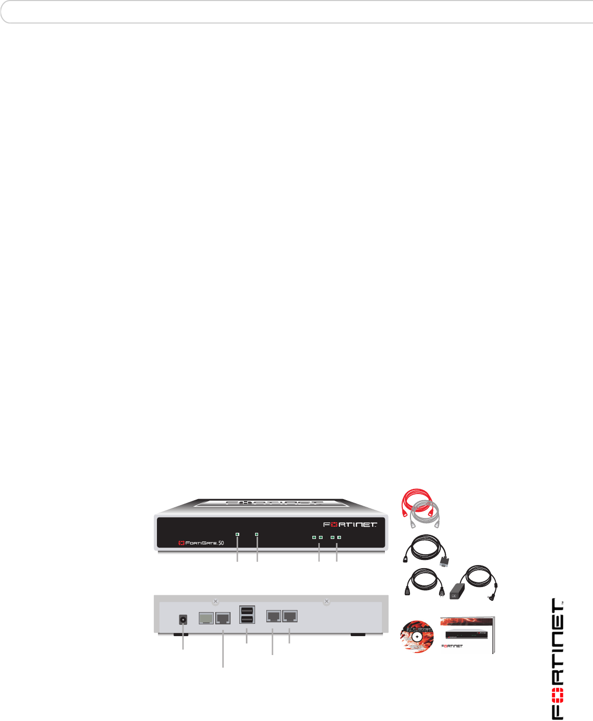
FortiGate-50A
The FortiGate-50A package contains the following items:
• FortiGate-50A Unified Threat Management System
• one orange crossover Ethernet cable (Fortinet part number CC300248)
• one gray straight-through Ethernet cable (Fortinet part number CC300249)
• one RJ-45 to DB-9 serial cable (Fortinet part number CC300247)
• one AC adapter and power cable
• FortiGate-50A QuickStart Guide
• Fortinet Tools and Documentation CD
Figure 1: FortiGate-50A package contents
PWR STATUS
INTERNAL EXTERNAL
LINK 100 LINK 100
PWR STAT US
A
Power
LED
Status
LED
External
Interface
Internal
Interface
Ethernet Cables:
Orange - Crossover
Grey - Straight-through
Power Cable Power Supply
RJ-45 to
DB-9 Serial Cable
Internal
External
DC+12V
USB
Back
Power USB Internal
Front
External
Modem Console
RJ-45 Serial
Connection
Documentation
FortiGate-50A
Copyright 2006 Fortinet Incorporated. All rights reserved.
Trademarks
Products mentioned in this document are trademarks.
QuickStart Guide
InternalExternal
LINK 100 LINK 100
PWR STATUS
FortiGate-50A/50B, FortiWiFi-50B and FortiGate-100 FortiOS 3.0 MR4 Install Guide
16 01-30004-0265-20070522
Package Contents Installing the FortiGate unit
Table 1: Technical Specifications
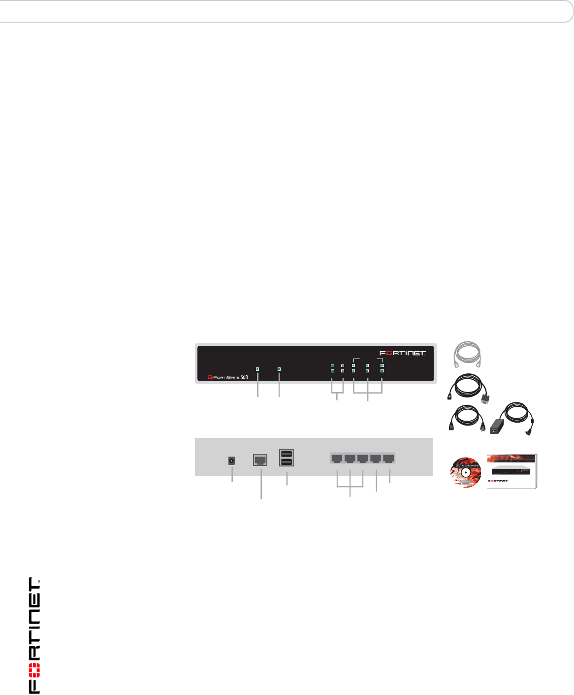
FortiGate-50B
The FortiGate-50B package contains the following items:
• FortiGate-50B Unified Threat Management System
• one gray straight-through Ethernet cable (Fortinet part number CC300249)
• one RJ-45 to DB-9 serial cable (Fortinet part number CC300247)
• one AC adapter and power cable
• FortiGate-50B QuickStart Guide
• Fortinet Tools and Documentation CD
Figure 2: FortiGate-50B package contents
Table 2: Technical Specifications
Dimensions 8.63 x 6.13 x 1.38 in. (21.9 x 15.6 x 3.5 cm)
Weight 1.5 lb. (0.68 kg)
Power Requirements DC input voltage: 12V
DC input current: 3A
Environmental
Specifications
Operating temperature: 32 to 104 F (0 to 40 C)
Storage temperature: -13 to 158 F (-25 to 70 C)
Humidity: 5 to 95% non-condensing
Dimensions 8.5 x 1.4 x 5.8in. (21.6 x 14.8 x 3.6 cm)
Weight 1.6 lb. (0.73 kg)
Power Requirements DC input voltage: 12V
DC input current: 3A
Environmental
Specifications
Operating temperature: 32 to 104 F (0 to 40 C)
Storage temperature: -13 to 158 F (-25 to 70 C)
Humidity: 5 to 95% non-condensing
123
USB WAN2 WAN1
DC+12V
WAN1 WAN2
POWER STATUS
INTERNAL
321
LINK / ACT
10/100
Power
Connection
RJ-45 Serial
Connection
USB WAN2
WAN1
Power
LED
Status
LED
Internal Interface,
switch connectors
1,2,3
WAN 1,2
Interface
Internal
Interface
Documentation
Ethernet Cables:
Grey - Straight-through
FortiGate-50B
Copyright 2006 Fortinet Incorporated. All rights reserved.
Trademarks
Products mentioned in this document are trademarks.
Power Cable Power Supply
RJ-45 to
DB-9 Serial Cable
QuickStart Guide
WAN1 WAN2
POWER STATUS
INTERNAL
321
LINK / ACT
10/100
Back
Front
Installing the FortiGate unit Package Contents
FortiGate-50A/50B, FortiWiFi-50B and FortiGate-100 FortiOS 3.0 MR4 Install Guide
01-30004-0265-20070522 17
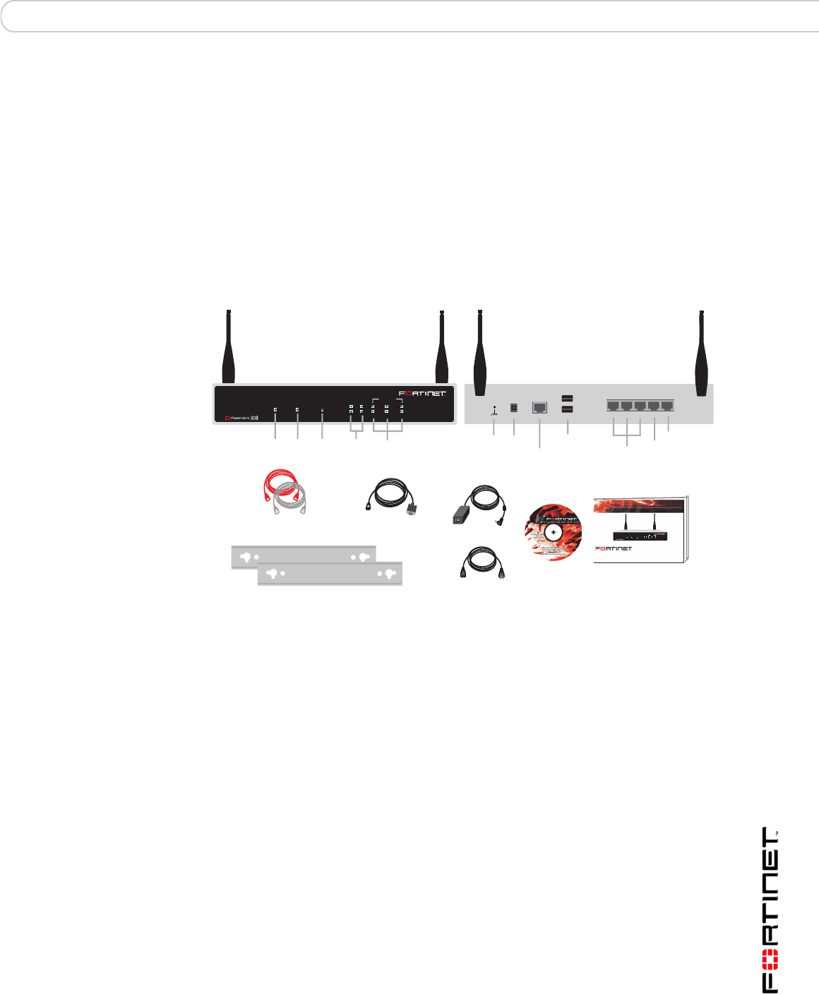
FortiWiFi-50B
The FortiWiFi-50B package contains the following items:
• FortiWiFi-50B Unified Threat Management System
• one gray straight-through Ethernet cable (Fortinet part number CC300249)
• one RJ-45 to DB-9 serial cable (Fortinet part number CC300247)
• one AC adapter and power cable
• two mounting brackets
• FortiWiFi-50B QuickStart Guide
• Fortinet Tools and Documentation CD
Figure 3: FortiWiFi-50B package contents
Table 3: Technical Specifications
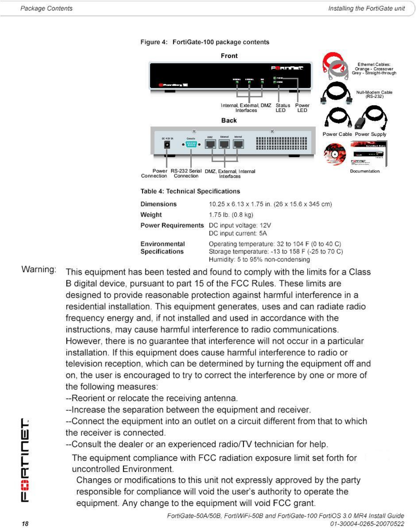
FortiGate-100
The FortiGate-100 package contains the following items:
• FortiGate-100 Unified Threat Management System
• one orange crossover Ethernet cable (Fortinet part number CC300248)
• one gray straight-through Ethernet cable (Fortinet part number CC300249)
• one null-modem cable
• one AC adapter and power cable
• FortiGate-100 QuickStart Guide
• Fortinet Tools and Documentation CD
Dimensions 8.5 x 1.4 x 5.8in. (21.6 x 14.8 x 3.6 cm)
Weight 1.6 lb. (0.73 kg)
Power Requirements DC input voltage: 12V
DC input current: 3A
Environmental
Specifications
Operating temperature: 32 to 104 F (0 to 40 C)
Storage temperature: -13 to 158 F (-25 to 70 C)
Humidity: 5 to 95% non-condensing
WAN1 WA N2
POWER STATUS
INTERNAL
321
LINK / ACT
10/100
WLAN
(PoE)
123
USB
CONSOLE WAN2 WAN1
DC+12V
Power
Connection
RJ-45 Serial
Connection
USBGround WAN2
WAN1
Internal Interface,
switch connectors
1,2,3
Back
Power
LED
Status
LED
WAN 1,2
Interface
Internal
Interface
WLAN
LED
Front
Ethernet Cables:
Orange - Crossover
Grey - Straight-through
Power Cable
Power Supply
RJ-45 to
DB-9 Serial Cable
2 Mounting Brackets
Documentation
FortiWiFi-50B
Copyright 2007 Fortinet Incorporated. All rights reserved.
Tradem arks
Products mentioned in this document are trademarks.
QuickStart Guide
WAN1 WAN2
POWER STATUS
INTERNAL
321
LINK / ACT
10/100
WLAN
(PoE)

Installing the FortiGate unit Mounting
FortiGate-50A/50B, FortiWiFi-50B and FortiGate-100 FortiOS 3.0 MR4 Install Guide
01-30004-0265-20070522 19
Mounting
Install the FortiGate unit on any stable, flat surface. Make sure the unit has at
least 1.5 in. (3.75 cm) of clearance on each side to allow for adequate air flow and
cooling.
Powering on the FortiGate unit
The FortiGate unit does not have an on/off switch.
To power on the FortiGate unit
1Connect the AC adapter to the power connection at the back of the FortiGate unit.
2Connect the AC adapter to the power cable.
3Connect the power cable to a power outlet.
The FortiGate unit starts and the Power and Status LEDs light up. The Status LED
flashes while the FortiGate unit starts up.
Table 5: FortiGate-50A and FortiGate-100 LED indicators
LED State Description
Power Green The FortiGate unit is powered on.
Off The FortiGate unit is powered off.
Status Flashing The FortiGate unit is starting up.
Off The FortiGate unit is running normally.
Internal
External
DMZ (FortiGate-100)
Green The correct cable is in use, and the connected
equipment has power.
Flashing
green
Network activity at this interface.
Off No link established.
Internal External
DMZ (FortiGate-100
interfaces
(back)
Green The correct cable is in use, and the connected
equipment has power.
Flashing
amber
Network activity at this interface.
Off No link established.

FortiGate-50A/50B, FortiWiFi-50B and FortiGate-100 FortiOS 3.0 MR4 Install Guide
20 01-30004-0265-20070522
Powering off the FortiGate unit Installing the FortiGate unit
Table 6: FortiGate-50B and FortiWiFi-50B LED indicators
Power over Ethernet
Power over Ethernet (PoE) is a method of powering Ethernet capable devices
using CAT5 Ethernet cable to carry both data and power to a device, eliminating
the need for a standard power source.
The FortiWiFi-50B includes the availability for PoE through the WAN1 port. The
FortiWiFi-50B supports the IEEE 802.3af standard as a Powered Device (PD)
using CAT5 Ethernet cable.
This enables you to place the FortiWiFi-50B in locations where connecting to a
standard power source is inconvenient or impractical.
Powering off the FortiGate unit
Always shut down the FortiGate operating system properly before turning off the
power switch to avoid potential hardware problems.
To power off the FortiGate unit
1From the web-based manager, go to System > Status.
2In the Unit Operation display, select Shutdown, or from the CLI, enter:
execute shutdown
3Disconnect the power supply.
Connecting to the FortiGate unit
There are two methods of connecting and configuring the basic FortiGate settings:
• the web-based manager
LED State Description
Power Green The FortiGate unit is powered on.
Off The FortiGate unit is powered off.
Status Flashing The FortiGate unit is starting up.
Off The FortiGate unit is running normally.
WLAN (WiFi-50B) Green Wireless port is up.
Off Wireless port is down.
Link/Activity Green The correct cable is in use, and the connected
equipment has power.
Flashing
green
Network activity at this interface.
Off No link established.
10/100 Green The interface is connected at 100 Mbps.
!
Caution: Attach a grounding cable to the Ground input in the FortiWiFi-50B and connect to
a grounding source to avoid potential damage to the device in the event of a power surge.

Installing the FortiGate unit Connecting to the FortiGate unit
FortiGate-50A/50B, FortiWiFi-50B and FortiGate-100 FortiOS 3.0 MR4 Install Guide
01-30004-0265-20070522 21
• the command line interface (CLI)
Web-based manager
You can configure and manage the FortiGate unit using HTTP or a secure HTTPS
connection from any computer running Microsoft Internet Explorer or recent
browser. The web-based manager supports multiple languages.
Use the web-based manager to configure most FortiGate settings, and monitor
the status of the FortiGate unit.
Command line interface
You can access the FortiGate command line interface (CLI) by connecting a
management computer serial port to the FortiGate serial console connector. You
can also use Telnet or a secure SSH connection to the CLI from any network that
is connected to the FortiGate unit, including the Internet.
Connecting to the web-based manager
Use the following procedure to connect to the web-based manager for the first
time. Configuration changes made with the web-based manager are effective
immediately, without resetting the firewall or interrupting service.
To connect to the web-based manager, you require:
• a computer with an Ethernet connection
• Microsoft Internet Explorer version 6.0 or higher or any recent version of most
popular web browser
• a crossover Ethernet cable or an Ethernet hub with two Ethernet cables
To connect to the web-based manager
1Set the IP address of the computer with an Ethernet connection to the static IP
address 192.168.1.2 with a netmask of 255.255.255.0.
2Using the crossover cable or the Ethernet hub and cables, connect the internal
interface of the FortiGate unit to the computer Ethernet connection.
3Start Internet Explorer and browse to the address https://192.168.1.99.
(remember to include the “s” in https://).
Note: Before starting Internet Explorer, (or any recent version of the most popular web
browser), ping to your FortiGate unit to see if the connection between the computer and the
FortiGate unit is working properly.
You can also configure the management computer to obtain an IP address
automatically using DHCP. The FortiGate DHCP server assigns the
management computer an IP address in the range 192.168.1.1 to
192.168.1.254.
50A
FortiGate-50A/50B, FortiWiFi-50B and FortiGate-100 FortiOS 3.0 MR4 Install Guide
22 01-30004-0265-20070522
Connecting to the FortiGate unit Installing the FortiGate unit
To support a secure HTTPS authentication method, the FortiGate unit ships with a
self-signed security certificate, which is offered to remote clients whenever they
initiate a HTTPS connection to the FortiGate unit. When you connect, the
FortiGate unit displays two security warnings in the browser.
The first warning prompts you to accept and optionally install the FortiGate unit’s
self-signed security certificate. If you do not accept the certificate, the FortiGate
unit refuses the connection. If you accept the certificate, the FortiGate login page
appears. The credentials entered are encrypted before they are sent to the
FortiGate unit. If you choose to accept the certificate permanently, the warning is
not displayed again.
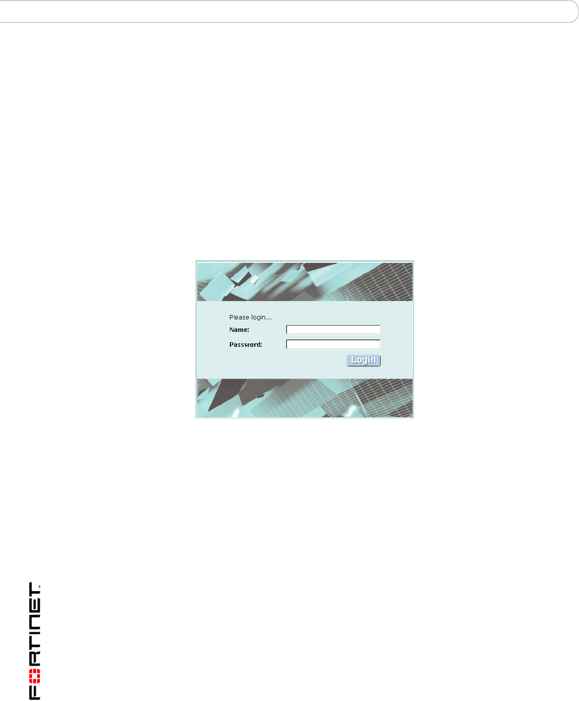
Just before the FortiGate login page is displayed, a second warning informs you
that the FortiGate certificate distinguished name differs from the original request.
This warning occurs because the FortiGate unit redirects the connection. This is
an informational message. Select OK to continue logging in.
Figure 5: FortiGate login
4Type admin in the Name field and select Login.
After logging into the web-based manager, the web browser displays the system
dashboard. The dashboard provides you with all system status information in one
location. For details on the information displayed on the dashboard, see the
FortiGate Administration Guide.
Command line interface
You can access the FortiGate command line interface (CLI) by connecting a
management computer serial port to the FortiGate serial console connector. You
can also use Telnet or a secure SSH connection to connect to the CLI from any
network that is connected to the FortiGate unit, including the Internet.
The CLI supports the same configuration and monitoring functionality as the
web-based manager. In addition, you can use the CLI for advanced configuration
options that are not available from the web-based manager. This guide contains
information about basic and advanced CLI commands. For a more complete
description about connecting to and using the FortiGate CLI, see the FortiGate
CLI Reference.

Installing the FortiGate unit Connecting to the FortiGate unit
FortiGate-50A/50B, FortiWiFi-50B and FortiGate-100 FortiOS 3.0 MR4 Install Guide
01-30004-0265-20070522 23
Connecting to the CLI
As an alternative to the web-based manager, you can install and configure the
FortiGate unit using the CLI. Configuration changes made with the CLI are
effective immediately, without resetting the firewall or interrupting service.
To connect to the FortiGate CLI you require:
• a computer with an available communications port
• the RJ-45 to DB-9 serial cable or null-modem cable included in your FortiGate
package.
• terminal emulation software such as HyperTerminal for Microsoft Windows.
To connect to the CLI
1Connect the RJ-45 to DB-9 serial cable or null-modem cable to the
communications port of your computer and to the FortiGate Console port.
2Start HyperTerminal, enter a name for the connection and select OK.
3Configure HyperTerminal to connect directly to the communications port on your
computer and select OK.
4Select the following port settings and select OK.
5Press Enter to connect to the FortiGate CLI.
The login prompt appears.
6Type admin and press Enter twice.
The following prompt is displayed:
Welcome!
Type ? to list available commands. For information about how to use the CLI, see
the FortiGate CLI Reference.
Note: The following procedure uses Microsoft Windows HyperTerminal software. You can
apply these steps to any terminal emulation program.
Bits per second 9600
Data bits 8
Parity None
Stop bits 1
Flow control None
FortiGate-50A/50B, FortiWiFi-50B and FortiGate-100 FortiOS 3.0 MR4 Install Guide
24 01-30004-0265-20070522
Quick installation using factory defaults Installing the FortiGate unit
Quick installation using factory defaults
The following procedure describes how to configure your internal network and the
FortiGate unit to use the FortiGate default settings.
1Connect the FortiGate unit between the internal network and the Internet and turn
on the power.
2Set the TCP/IP properties of the network computers to obtain an IP address
automatically and a DNS server IP address automatically (using DHCP).
3From the management computer, browse to https://192.168.1.99.
4Go to System > Network > Interface and select Edit for the External or WAN1
interface.
5Select one of the following Addressing modes
• Manual: enter a static IP address and netmask, select OK, and go to step 6
• DHCP: to get an IP address from the Internet Service Provider (ISP) select
DHCP and go to step 9
• PPPoE: to get an IP address from the ISP select PPPoE and go to step 9
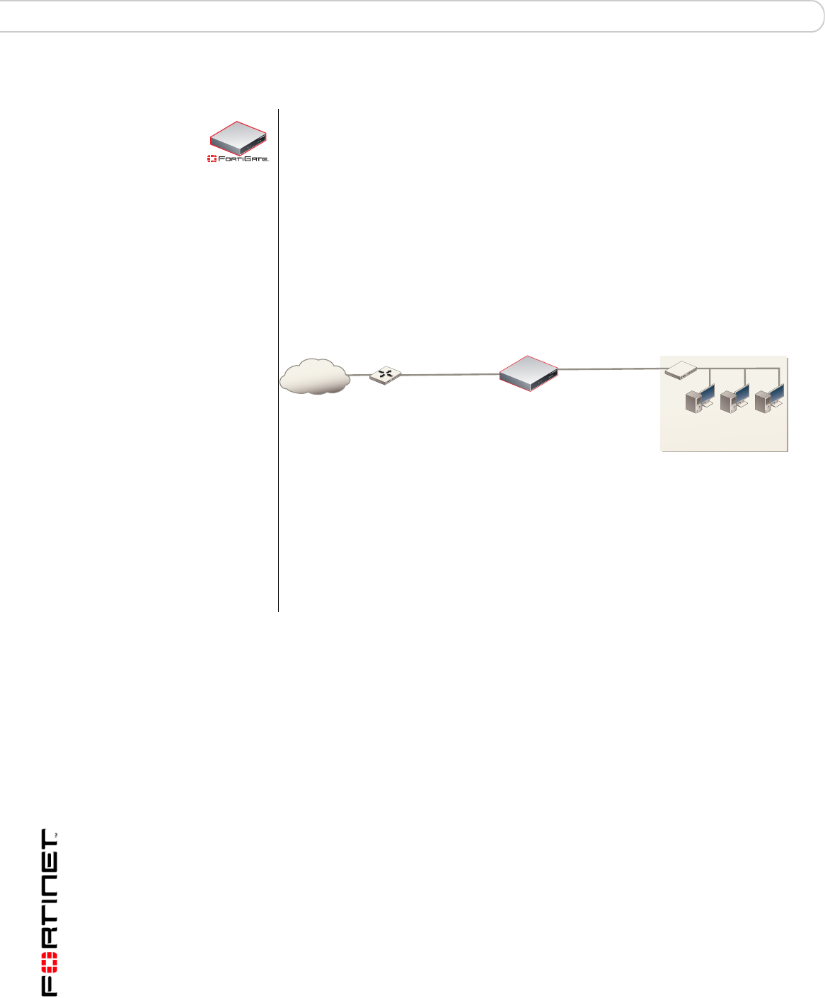
You can quickly set up your FortiGate unit for a home or small office using the
web-based manager and the factory default FortiGate configuration. All you
need to do is set your network computers to obtain an IP address automatically
and to obtain DNS server IP addresses automatically (using DHCP), access the
web-based manager, and configure the required settings for the FortiGate
external interface. You can also configure FortiGate DNS servers and add a
FortiGate default route if needed.
The FortiGate internal interface acts as a DHCP server for the internal network,
automatically assigning IP addresses to computers (up to 100 computers) in the
range of 192.168.1.110 –192.168.1.210.
Figure 6: Quick configuration using default settings
The FortiGate DHCP server also assigns the DNS server IP address
192.168.1.99 to each computer on the internal network. As a result, the
FortiGate unit internal interface acts as a DNS server for the internal network.
Using DNS forwarding, the FortiGate unit forwards DNS requests received from
the internal network to the DNS server IP addresses added to the FortiGate unit
configuration and returns lookup results to the internal network.
For more information about default DHCP server settings see “Factory default
DHCP server configuration” on page 28.
50A
FortiGate-50A
Router
Internet
Obtain IP address
and DNS server IP address
automatically
Internal interface
192.168.1.99
DHCP server and DNS
server for the internal network
External interface
Configuring Manual IP,
DHCP, or PPPoE addressing

Installing the FortiGate unit Quick installation using factory defaults
FortiGate-50A/50B, FortiWiFi-50B and FortiGate-100 FortiOS 3.0 MR4 Install Guide
01-30004-0265-20070522 25
6Go to System > Network > Options.
7Select one of the following DNS settings
• Obtain DNS server address automatically: select to get the DNS addresses
from the ISP, select Apply
• Use the following DNS server addresses: select and enter the DNS server
addresses given to you by the ISP, select Apply
8Go to Router > Static, edit route #1 and change Gateway to the default gateway
IP address from the ISP and select OK.
Network configuration is complete. Proceed to “Next steps” on page 46.
9Select Retrieve default gateway from server and Override internal DNS options if
your ISP supports them, select OK, and proceed to “Next steps” on page 46.
Go to step 6 if you are not selecting these options.

FortiGate-50A/50B, FortiWiFi-50B and FortiGate-100 FortiOS 3.0 MR4 Install Guide
26 01-30004-0265-20070522
Quick installation using factory defaults Installing the FortiGate unit

Factory defaults
FortiGate-50A/50B, FortiWiFi-50B and FortiGate-100 FortiOS 3.0 MR4 Install Guide
01-30004-0265-20070522 27
Factory defaults
The FortiGate unit ships with a factory default configuration. The default
configuration enables you to connect to and use the FortiGate web-based
manager to configure the FortiGate unit onto the network. To configure the
FortiGate unit, you add an administrator password, change network interface IP
addresses, add DNS server IP addresses, and, if required, configure basic
routing.
If you plan to operate the FortiGate unit in Transparent mode, you can switch to
Transparent mode from the factory default configuration and then configure the
FortiGate unit onto the network.
Once you complete the network configuration, you can perform additional
configuration tasks such as setting system time, configuring virus and attack
definition updates, and registering the FortiGate unit.
The factory default firewall configuration includes a single network address
translation (NAT) policy that allows users on your internal network to connect to
the external network, and stops users on the external network from connecting to
the internal network. You can add more firewall policies to provide more control of
the network traffic passing through the FortiGate unit.
You can use the factory default protection profiles to apply different levels of
antivirus protection, web content filtering, spam filtering, and IPS to the network
traffic that is controlled by firewall policies.
This section includes the following topics:
•Factory default DHCP server configuration
•Factory default NAT/Route mode network configuration
•Factory default Transparent mode network configuration
•Factory default firewall configuration
•Factory default protection profiles
•Restoring the default settings

FortiGate-50A/50B, FortiWiFi-50B and FortiGate-100 FortiOS 3.0 MR4 Install Guide
28 01-30004-0265-20070522
Factory defaults
Factory default DHCP server configuration
Table 7: FortiGate DHCP Server default configuration
Factory default NAT/Route mode network configuration
When the FortiGate unit is first powered on, it is running in NAT/Route mode and
has the basic network configuration listed in Table 8 on page 28. This
configuration enables you to connect to the FortiGate unit web-based manager
and establish the configuration required to connect the FortiGate unit to the
network. In Table 8 on page 28, HTTPS administrative access means you can
connect to the web-based manager using HTTPS protocol through this interface.
Ping administrative access means this interface responds to ping requests.
With the FortiGate-50 series, you can quickly configure the internal network and the
FortiGate unit by using the factory default DHCP server settings. See “Quick
installation using factory defaults” on page 24
50A
Name internal_dhcp_server
Interface Internal
Default Gateway 192.168.1.99
IP Range 192.168.1.110 – 192.168.1.210
Network Mask 255.255.255.0
Lease Time 7 days
DNS Server 1 192.168.1.99
Table 8: Factory default NAT/Route mode network configuration
Administrator
account
User name: admin
Password: (none)
Internal interface
IP: 192.168.1.99
Netmask: 255.255.255.0
Administrative Access: HTTP, HTTPS,
Ping
External interface
(FortiGate-50A/100)
WAN1 (FortiGate-50B/
WiFi-50B)
IP: 192.168.100.99
Netmask: 255.255.255.0
Administrative Access: Ping
WAN2 (FortiGate-50B/
WiFi-50B)
IP: 192.168.101.99
Netmask: 255.255.255.0
Administrative Access: Ping
DMZ interface
(FortiGate-50A/100)
IP: 10.10.10.1
Netmask: 255.255.255.0
Administrative Access: HTTPS, Ping
WLAN interface
(FortiWiFi-50B)
IP: 10.10.80.1
Netmask: 255.255.255.0
Administrative Access: Ping

Factory defaults
FortiGate-50A/50B, FortiWiFi-50B and FortiGate-100 FortiOS 3.0 MR4 Install Guide
01-30004-0265-20070522 29
Factory default Transparent mode network configuration
In Transparent mode, the FortiGate unit has the default network configuration
listed in Table 9.
Factory default firewall configuration
FortiGate firewall policies control how all traffic is processed by the FortiGate unit.
Until firewall policies are added, no traffic can pass through the FortiGate unit.
The factory default configuration contains one firewall policies to allows all traffic
through the FortiGate unit. To allow specific traffic through the FortiGate unit, you
can add firewall policies. See the FortiGate Administration Guide for information
about adding firewall policies.
The following firewall configuration settings are included in the default firewall
configuration to make it easier to add firewall policies.
Network Settings
Default Gateway (for default route) 192.168.100.1
Interface connected to external network
(for default route)
external
Default Route
A default route consists of a default gateway and the name of
the interface connected to the external network (usually the
Internet). The default gateway directs all non-local traffic to this
interface and to the external network.
Primary DNS Server 65.39.139.53
Secondary DNS Server 65.39.139.63
Table 8: Factory default NAT/Route mode network configuration (Continued)
Table 9: Factory default Transparent mode network configuration
Administrator account User name: admin
Password: (none)
Management IP IP: 0.0.0.0
Netmask: 0.0.0.0
DNS Primary DNS Server: 65.39.139.53
Secondary DNS Server: 65.39.139.63
Administrative access
Internal HTTPS, Ping
External Ping
DMZ HTTPS, Ping

FortiGate-50A/50B, FortiWiFi-50B and FortiGate-100 FortiOS 3.0 MR4 Install Guide
30 01-30004-0265-20070522
Factory defaults
Table 10: Factory default firewall configuration
The factory default firewall configuration is the same in NAT/Route mode and
Transparent mode.
Factory default protection profiles
Use protection profiles to apply different protection settings for traffic controlled by
firewall policies. You can use protection profiles to:
• configure antivirus protection for HTTP, FTP, IMAP, POP3, and SMTP firewall
policies
• configure Web filtering for HTTP firewall policies
• configure Web category filtering for HTTP firewall policies
• configure spam filtering for IMAP, POP3, and SMTP firewall policies
• enable the Intrusion Protection System (IPS) for all services
• enable content logging for HTTP, FTP, IMAP, POP3, and SMTP firewall
policies
By using protection profiles, you can build protection configurations that can be
applied to different types of firewall policies. This allows you to customize types
and levels of protection for different firewall policies.
For example, while traffic between internal and external addresses might need
strict protection, traffic between trusted internal addresses might need moderate
protection. You can configure firewall policies for different traffic services to use
the same or different protection profiles.
You can add Protection profiles to NAT/Route mode and Transparent mode
firewall policies. The FortiGate unit includes four protection profiles.
Configuration setting Name Description
Firewall policy Internal -> External Source: All Destination: All
Firewall address All Firewall address matches the source or
destination address of any packet.
Pre-defined service More than 50
predefined services
Select from any of the 50 pre-defined
services to control traffic through the
FortiGate unit that uses that service.
Recurring schedule Always The recurring schedule is valid at any
time.
Protection Profiles Strict, Scan, Web,
Unfiltered
Control how the FortiGate unit applies
virus scanning, web content filtering, spam
filtering, and IPS.
Strict To apply maximum protection to HTTP, FTP, IMAP, POP3, and SMTP
traffic. You may not use the strict protection profile under normal
circumstances but it is available if you have problems with viruses and
require maximum screening.
Scan To apply antivirus scanning and file quarantining to HTTP, FTP, IMAP,
POP3, and SMTP content traffic.
Web To apply antivirus scanning and web content blocking to HTTP content
traffic. You can add this protection profile to firewall policies that control
HTTP traffic.
Unfiltered To apply no scanning, blocking or IPS. Use if you do not want to apply
content protection to content traffic. You can add this protection profile to
firewall policies for connections between highly trusted or highly secure
networks where content does not need to be protected.

Factory defaults Restoring the default settings
FortiGate-50A/50B, FortiWiFi-50B and FortiGate-100 FortiOS 3.0 MR4 Install Guide
01-30004-0265-20070522 31
Restoring the default settings
You can revert to the factory default settings if you change a network setting and
are unable to recover from it.
Restoring the default settings using the web-based manager
To reset the default settings
1Go to System > Status.
2In Unit Operation Display, select Reset.
Restoring the default settings using the CLI
To reset the default settings enter the following command:
execute factoryreset
!
Caution: This procedure deletes all changes you have made to the FortiGate configuration
and reverses the system to its original configuration, including resetting interface
addresses.

FortiGate-50A/50B, FortiWiFi-50B and FortiGate-100 FortiOS 3.0 MR4 Install Guide
32 01-30004-0265-20070522
Restoring the default settings Factory defaults

Configuring the FortiGate unit Planning the FortiGate configuration
FortiGate-50A/50B, FortiWiFi-50B and FortiGate-100 FortiOS 3.0 MR4 Install Guide
01-30004-0265-20070522 33
Configuring the FortiGate unit
This section provides an overview of the operating modes of the FortiGate unit.
Before beginning to configure the FortiGate unit, you need to plan how to
integrate the unit into your network. Your configuration plan depends on the
operating mode you select: NAT/Route mode or Transparent mode.
This section includes the following topics:
•Planning the FortiGate configuration
•Preventing the public interface from responding to ping requests
•NAT/Route mode installation
•Transparent mode installation
•Next steps
Planning the FortiGate configuration
Before you configure the FortiGate unit, you need to plan how to integrate the unit
into the network. Among other things, you must decide whether you want the unit
to be visible to the network, which firewall functions you want it to provide, and
how you want it to control the traffic flowing between its interfaces.
Your configuration plan depends on the operating mode you select. You can also
configure the FortiGate unit and the network it protects using the default settings.
NAT/Route mode
In NAT/Route mode, the FortiGate unit is visible to the network. Like a router, all
its interfaces are on different subnets. The following interfaces are available in
NAT/Route mode:
Modem is the interface for connecting an external modem to the FortiGate-50A.
See “Configuring the modem for the FortiGate-50A” on page 53.
You can add firewall policies to control whether communications through the
FortiGate unit operating in NAT or Route mode. Firewall policies control the flow
of traffic based on the source address, destination address, and service of each
packet. In NAT mode, the FortiGate unit performs network address translation
before it sends the packet to the destination network. In Route mode, there is no
address translation.
Table 11: NAT/Route mode network segments
FortiGate Unit Internal Interface External
Interface
Other
FortiGate-50A Internal External Modem
FortiGate-50B Internal WAN1 WAN2
FortiWiFi-50B Internal WAN1 WAN2
FortiGate-100A Internal External DMZ
FortiGate-50A/50B, FortiWiFi-50B and FortiGate-100 FortiOS 3.0 MR4 Install Guide
34 01-30004-0265-20070522
Planning the FortiGate configuration Configuring the FortiGate unit
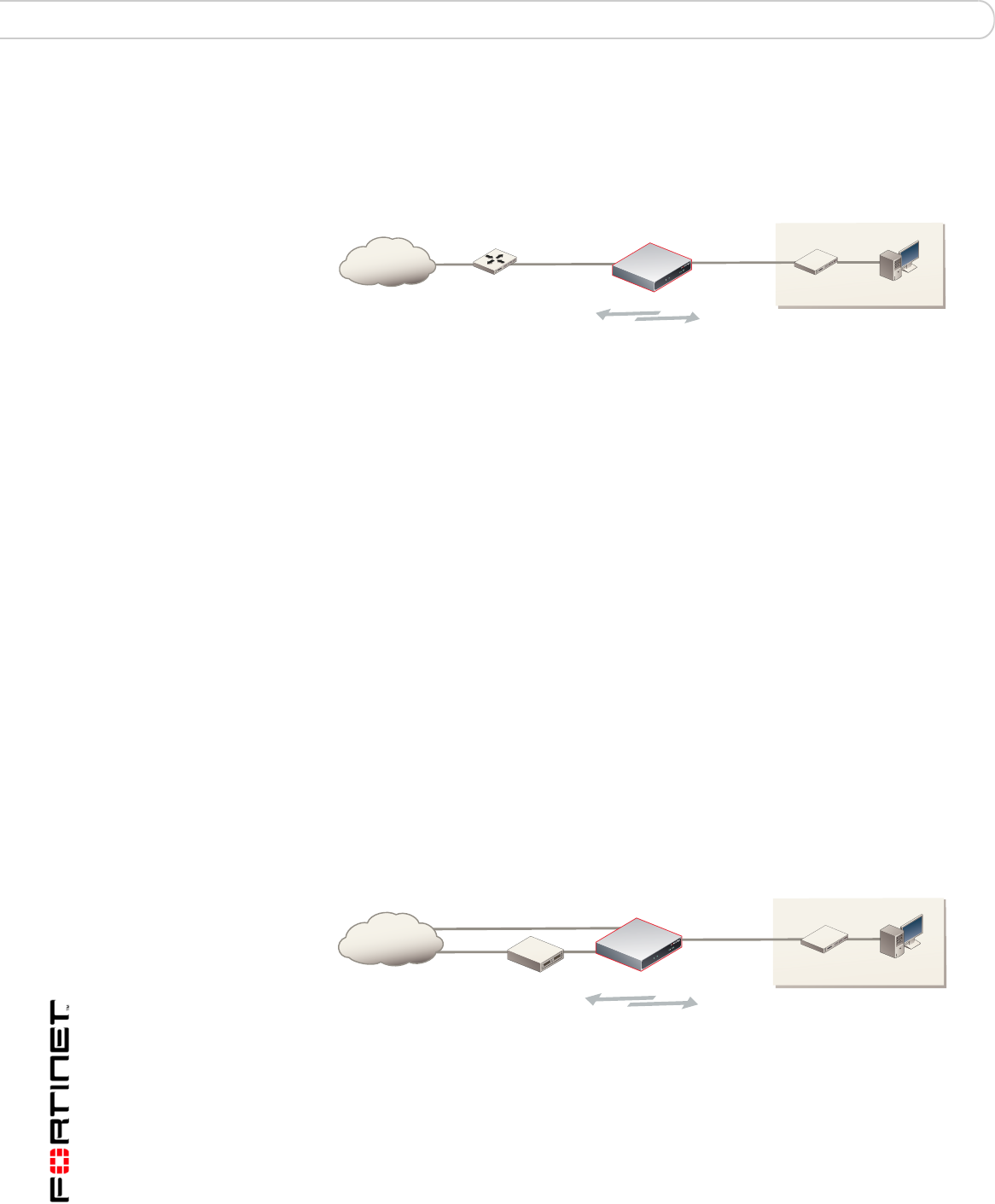
You typically use NAT/Route mode when the FortiGate unit is operating as a
gateway between private and public networks. In this configuration, you create
NAT mode firewall policies to control traffic flowing between the internal, private
network and the external, public network (usually the Internet).
Figure 7: Example NAT/Route mode network configuration for a FortiGate-50A.
.
NAT/Route mode with multiple external network connections
In NAT/Route mode, you can configure the FortiGate unit with multiple redundant
connections to the external network (usually the Internet).
For example, you could create the following configuration:
• External or WAN1 is the default interface to the external network (usually the
Internet)
• Modem is the redundant interface to the external network for the
FortiGate-50A
• WAN2 is the redundant interface to the external network on the FortiGate-50B
and FortiWiFi-50B.
• DMZ is the redundant interface to the external network on the FortiGate-100
• Internal is the interface to the internal network
You must configure routing to support redundant Internet connections. Routing
can automatically redirect connections from an interface if its connection to the
external network fails.
Otherwise, security policy configuration is similar to a NAT/Route mode
configuration with a single Internet connection. You would create NAT mode
firewall policies to control traffic flowing between the internal, private network and
the external, public network (usually the Internet).
Figure 8: NAT/Route multiple internet connection configuration for a FortiGate-50A
.
Internal network
FortiGate-50A
Internet
Router
External
204.23.1.5
Internal
192.168.1.99
NAT mode policies controlling
traffic between internal and
external networks.
192.168.1.3
FortiGate-50A
Internet
Internal network
External
204.23.1.5 Internal
192.168.1.1
NAT mode policies controlling
traffic between internal and
external networks.
MODEM
192.168.1.3
Configuring the FortiGate unit Preventing the public interface from responding to ping requests
FortiGate-50A/50B, FortiWiFi-50B and FortiGate-100 FortiOS 3.0 MR4 Install Guide
01-30004-0265-20070522 35
Transparent mode
In Transparent mode, the FortiGate unit is invisible to the network. Similar to a
network bridge, all FortiGate interfaces must be on the same subnet. You only
have to configure a management IP address so that you can make configuration
changes. The management IP address is also used for antivirus and attack
definition updates.
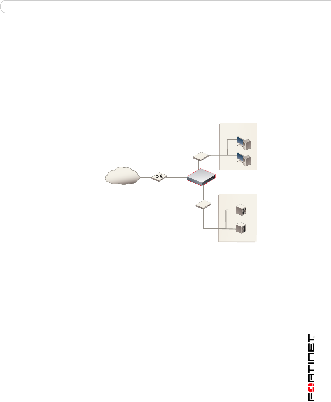
You typically use the FortiGate unit in Transparent mode on a private network
behind an existing firewall or behind a router. The FortiGate unit performs firewall
functions, IPSec VPN, virus scanning, IPS web content filtering, and Spam
filtering.
Figure 9: Example Transparent mode network configuration for a FortiGate-100
Preventing the public interface from responding to ping
requests
The factory default configuration of your FortiGate unit allows the default public
interface to respond to ping requests. The default public interface is also called
the default external interface, and is the interface of the FortiGate unit that is
usually connected to the Internet.
For the most secure operation, you should change the configuration of the
external interface so that it does not respond to ping requests. Not responding to
ping requests makes it more difficult for a potential attacker to detect your
FortiGate unit from the Internet.
A FortiGate unit responds to ping requests if ping administrative access is
enabled for that interface. You can use the following procedures to disable ping
access for the external interface of a FortiGate unit. You can use the same
procedure for any FortiGate interface. You can also use the same procedure in
NAT/Route or Transparent mode.
Internal network
Internal
Internet
Router FortiGate-100
External
DMZ
Internal
DMZ network
Web Server
Mail Server

FortiGate-50A/50B, FortiWiFi-50B and FortiGate-100 FortiOS 3.0 MR4 Install Guide
36 01-30004-0265-20070522
NAT/Route mode installation Configuring the FortiGate unit
To disable ping administrative access from the web-based manager
1Log into the FortiGate web-based manager.
2Go to System > Network > Interface.
3Choose the external interface and select Edit.
4Clear the Ping Administrative Access check box.
5Select OK.
To disable ping administrative access from the FortiGate CLI
1Log into the FortiGate CLI.
2Disable administrative access to the external interface. Enter:
config system interface
edit external
unset allowaccess
end
NAT/Route mode installation
This section describes how to install the FortiGate unit in NAT/Route mode. This
section includes the following topics:
•Preparing to configure the FortiGate unit in NAT/Route mode
•DHCP or PPPoE configuration
•Using the web-based manager
•Using the command line interface
•Connecting the FortiGate unit to the network(s)
•Configuring the networks
Preparing to configure the FortiGate unit in NAT/Route mode
Use Table 12 on page 36 to gather the information you need to customize
NAT/Route mode settings.
You can configure the FortiGate unit in two ways:
• The web-based manager GUI is a complete interface for configuring most
settings. See “Using the web-based manager” on page 37.
• The command line interface (CLI) is a complete text-based interface for
configuring all settings. See “Using the command line interface” on page 39.
The method you choose depends on the complexity of the configuration, access
and equipment, and the type of interface you are most comfortable using.
Table 12: NAT/Route mode settings

Configuring the FortiGate unit NAT/Route mode installation
FortiGate-50A/50B, FortiWiFi-50B and FortiGate-100 FortiOS 3.0 MR4 Install Guide
01-30004-0265-20070522 37
DHCP or PPPoE configuration
You can configure any FortiGate interface to acquire its IP address from a DHCP
or PPPoE server. Your Internet Service Provider (ISP) may provide IP addresses
using one of these protocols.
To use the FortiGate DHCP server, you need to configure an IP address range
and default route for the server. No configuration information is required for
interfaces that are configured to use DHCP.
PPPoE requires you to supply a user name and password. In addition, PPPoE
unnumbered configurations require you to supply an IP address. Use Table 13 to
record the information you require for your PPPoE configuration.
Table 13: PPPoE setting
Using the web-based manager
You can use the web-based manager for the initial configuration of the FortiGate
unit and all FortiGate unit settings. For information about connecting to the
web-based manager, see “Connecting to the web-based manager” on page 21.
Configuring basic settings
After connecting to the web-based manager, use the following procedures to
complete the basic configuration of the FortiGate unit.
Administrator Password:
Internal
IP: _____._____._____._____
Netmask: _____._____._____._____
External/WAN1
IP: _____._____._____._____
Netmask: _____._____._____._____
DMZ/WAN2
IP: _____._____._____._____
Netmask: _____._____._____._____
Network settings
Default Gateway: _____._____._____._____
(Interface connected to
external network)
A default route consists of a default gateway and the name of the
interface connected to the external network (usually the Internet).
The default gateway directs all non-local traffic to this interface and
to the external network.
Primary DNS Server: _____._____._____._____
Secondary DNS Server: _____._____._____._____
User name:
Password:
Note: The FortiGate-50A includes default DHCP settings.

FortiGate-50A/50B, FortiWiFi-50B and FortiGate-100 FortiOS 3.0 MR4 Install Guide
38 01-30004-0265-20070522
NAT/Route mode installation Configuring the FortiGate unit
To add/change the administrator password
1Go to System > Admin > Administrators.
2Select the Change Password icon for the admin administrator.
3Enter the new password and enter it again to confirm.
4Select OK.
To configure interfaces
1Go to System > Network > Interface.
2Select the edit icon for an interface.
3Set the addressing mode for the interface.
Choose from manual, DHCP, or PPPoE.
4Complete the addressing configuration.
• For manual addressing, enter the IP address and netmask for the interface.
• For DHCP addressing, select DHCP and any required settings.
• For PPPoE addressing, select PPPoE, and enter the username and password
and any other required settings.
For information about how to configure these and other interface settings, see the
FortiGate online help or the FortiGate Administration Guide.
5Select OK.
6Repeat this procedure for each interface.
To configure DNS server settings
1Go to System > Network > Options.
2Enter the IP address of the primary DNS server.
3Enter the IP address of the secondary DNS server.
4Select Apply.
Adding a default route
Add a default route to configure where the FortiGate unit sends traffic destined for
an external network (usually the Internet). Adding the default route also defines
which interface is connected to an external network. The default route is not
required if the interface connected to the external network is configured using
DHCP or PPPoE.
To add a default route
1Go to Router > Static.
2If the Static Route table contains a default route (IP and Mask set to 0.0.0.0),
select the Delete icon to delete this route.
3Select Create New.
Note: If you change the IP address of the interface you are connecting to, you must
connect through a web browser again using the new address. Browse to https:// followed
by the new IP address of the interface. If the new IP address of the interface is on a
different subnet, you may have to change the IP address of your computer to the same
subnet.

Configuring the FortiGate unit NAT/Route mode installation
FortiGate-50A/50B, FortiWiFi-50B and FortiGate-100 FortiOS 3.0 MR4 Install Guide
01-30004-0265-20070522 39
4Set Destination IP to 0.0.0.0.
5Set Mask to 0.0.0.0.
6Set Gateway to the default gateway IP address.
7Set Device to the interface connected to the external network.
8Select OK.
Verifying the web-based manager configuration
To verify access settings, go to the interface you want to verify and select the edit
icon. The Administrative Access field should have check marks beside the
settings you chose in the preceeding steps.
Verify the connection
To verify your connection, try the following:
• browse to www.fortinet.com
• retrieve or send email from your email account
If you cannot browse to the web site or retrieve/send email from your account,
review the previous steps to ensure all information was entered correctly and try
again.
Using the command line interface
You can also configure the FortiGate unit using the command line interface (CLI).
For information about connecting to the CLI, see “Connecting to the CLI” on
page 23.
Configuring the FortiGate unit to operate in NAT/Route mode
Use the information you gathered in Table 12 on page 36 to complete the
following procedures.
To add/change the administrator password
1Log in to the CLI.
2Change the admin administrator password. Enter:
config system admin
edit admin
set password <psswrd>
end
To configure interfaces
1Log in to the CLI.
2Set the IP address and netmask of the internal interface to the internal IP address
and netmask you recorded in Table 12 on page 36. Enter:

FortiGate-50A/50B, FortiWiFi-50B and FortiGate-100 FortiOS 3.0 MR4 Install Guide
40 01-30004-0265-20070522
NAT/Route mode installation Configuring the FortiGate unit
config system interface
edit <interface>
set mode static
set ip <address_ip> <netmask>
end
Example
config system interface
edit internal
set mode static
set ip 192.168.120.99 255.255.255.0
end
3Set the IP address and netmask of the external interface to the external IP
address and netmask you recorded in Table 12 on page 36.
config system interface
edit <interface>
set mode static
set ip <address_ip> <netmask>
end
Example
config system interface
edit external
set mode static
set ip 10.10.1.5 255.255.255.0
end
To set the external interface to use DHCP, enter:
config system interface
edit <interface>
set mode dhcp
end
To set the external interface to use PPPoE, enter:
config system interface
edit <interface>
set mode pppoe
set connection enable
set username <name_str>
set password <psswrd>
end
4Use the same syntax to set the IP address of each FortiGate interface as required.
5Confirm that the addresses are correct. Enter:
get system interface
The CLI lists the IP address, netmask, and other settings for each of the FortiGate
interfaces.
To configure DNS server settings
Set the primary and secondary DNS server IP addresses. Enter